Embed Size (px)
Citation preview

MANUAL OF CONTRACT DOCUMENTS FOR ROAD WORKS VOLUME 1 SPECIFICATION FOR ROAD WORKS
March 2003 1
SERIES 600 EARTHWORKS Contents Clause Title Page 601 Classification, Definitions and Uses of Earthworks Materials 2 602 General Requirements 4 603 Forming of Cuttings and Cutting Slopes 6 604 Excavation for Foundations 8 605 Special Requirements for Class 3 Material 8 606 Watercourses 8 607 Explosives and Blasting for Excavation 9 608 Construction of Fills 11 609 Geotextiles Used to Separate Earthworks Materials 10 13 610 Fill to Structures 14 611 Fill Above Structural Concrete Foundations 15 612 Compaction of Fills 15 613 Sub-formation and Capping 21 614 Cement Stabilisation to Form Capping 22 615 Lime Stabilisation to Form Capping 24 616 Preparation and Surface Treatment of Formation 26 617 Use of Sub-formation or Formation by Construction Plant 27 618 Topsoiling 28 619 Earthwork Environmental Bunds 31 620 Landscape Areas 32 621 Strengthened Embankments 32 622 Earthworks for Reinforced Soil and Anchored Earth Structures 32 623 Earthworks for Corrugated Steel Buried Structures 34 624 Ground Anchorages 35 625 Crib Walling 36 626 Gabions 36 627 Swallow Holes and Other Naturally Occurring Cavities 36 628 Disused Mine Workings 37 629 Instrumentation and Monitoring 37 630 Ground Improvement 37 631 Earthworks Materials Tests 39 632 Determination of Moisture Condition Value (MCV) of Earthworks Materials 39 633 Determination of Undrained Shear Strength of Remoulded Cohesive Material 39 634 Determination of Saturation Moisture Content (SMC) of Chalk 40 635 10% Fines Value and Other Tests of Particle Soundness 40 636 Determination of Effective Angle of Internal Friction (./) and Effective Cohesion (c/)
of Earthworks Materials 40 637 Determination of Resistivity (rs) to Assess Corrosivity of Soil, Rock or Earthworks Materials 41 638 Determination of Redox Potential (Eh) to Assess Corrosivity of Earthworks Materials for
Reinforced Soil and Anchored Earth Structures 42 639 Determination of Coefficient of Friction and Adhesion Between Fill and Reinforcing
Elements or Anchor Elements for Reinforced Soil and Anchored Earth Structures 42 640 Determination of Permeability of Earthworks Materials 43 641 Determination of Available Lime Content of Lime for Stabilized Capping 43 642 Determination of the Constrained Soil Modulus (M*) of Earthworks Materials
for Corrugated Steel Buried Structures 44 643 Lime and Cement Stabilization to Form Capping 28 Tables 6/1 to 6/5 45
Tables 6/1 to 6/5 ume 1 home page
EARTHWORKS

Volume 1 Series 600 Specification for Road Works Earthworks
March 2003 2
601 Classification, Definitions and Uses of Earthworks Materials General Classification 1 Earthworks materials shall fall into one or other of the following general classifications: (i) Acceptable material: material
excavated from within the Site or imported on to the Site which meets the requirements of Table 6/1 and Appendix 6/1 for acceptability for use in the Permanent Works;
(ii) Unacceptable material Class U1 as
defined in sub-Clause 2 of this Clause: material excavated from within the Site which, unless processed so that it meets the requirements of Table 6/1 and Appendix 6/1, shall not be used in the Permanent Works;
(iii) Unacceptable material Class U2 as
defined in sub-Clause 3 of this Clause: material excavated from within the Site, which shall not be used in the Permanent Works.
2 Unacceptable material Class U1 shall be: (i) material which does not comply
with the permitted constituents and material properties of Table 6/1 and Appendix 6/1 for acceptable material;
(ii) material, or constituents of
materials, composed of the following unless otherwise described in Appendix 6/1:
a) material similar to: b) logs, stumps and perishable
material; c) materials in a frozen
condition; d) clay having a liquid limit
determined in accordance with BS 1377 : Part 2, exceeding 80 or plasticity index determined in accordance with BS 1377 : Part 2, exceeding 55;
e) material susceptible to
spontaneous combustion f) non-hazardous materials
other than those permitted in Table 6/1 and Appendix 6/1.
3 Unacceptable material Class U2 shall be: (i) material having hazardous
chemical or physical properties requiring special measures for its excavation, handling, storing, transportation, deposition and disposal.
4 Where required in Appendix 6/1 unacceptable material shall be processed by mechanical, chemical or other means to render the material acceptable for use in the Permanent Works in accordance with the requirements of Table 6/1 and Appendix 6/1. Definitions 5 Chalk shall mean:

Volume 1 Series 600 Specification for Road Works Earthworks
March 2003 3
(ii) Any porous material of natural origin composed essentially of calcium carbonate and identified as chalk on the maps produced by the Maltese Geological Survey;
(iii) Material designated as Class 3 in
Appendix 6/1. 6 Argillaceous rock shall mean shale mudstones siltstones slates and micaceous schists composed of particles of clay and silt and mica. 7 Formation shall be the top surface of capping. Where no capping is required formation shall be the surface of the subgrade or embankment directly below the pavement, unless otherwise shown on the Drawings. 8 Sub-formation shall be the top surface of earthworks at the underside of capping. 9 Stabilization shall mean the spreading of cement or lime or both on a layer of deposited or intact granular or cohesive material, and the subsequent process of pulverizing and mixing followed by appropriate compaction to form the whole or a constituent layer of a capping. In Malta the term cement stabilization is used for cement bound material, which is a constituent layer of the pavement. 10 Where ‘recycled aggregate’ is used in this Series, the material shall be aggregate resulting from the processing of material used in a construction process. The aggregate shall have been tested in accordance with Clause 710, and the content of all foreign materials (including wood, plastic and metal) shall not exceed 1% by mass. Where
‘recycled aggregate except recycled asphalt’ is used in this Series, the aggregate shall have been tested in accordance with Clause 710 and shall not contain any mineral aggregate with a bituminous binder, and the content of all foreign materials shall not exceed 1%. Use of Fill Materials 11 In addition to any grading requirements the maximum particle size of any fill material shall be no more than two-thirds of the compacted layer thickness except that cobbles having an equivalent diameter of more than 150 mm shall not be deposited beneath verges or central reserves within 1.30 m of the finished surface. 12 Isolated boulders with a equivalent diameter less than 250mm may be incorporated in embankments not of rock fill provided the specified compaction requirements are met. These boulders shall not be placed less than 600mm below formation level of carriageways or hard-shoulders where there is no capping; or less than 600mm below sub formation where there is capping. 13 Materials with a water soluble sulfate content exceeding 0.25 grams of sulfate (expressed as SO3) per liter when tested in accordance with BS 1377 : Part 3 shall not be deposited within 500 mm, or other distances described in Appendix 6/3, of metallic items forming part of the Permanent Works. 14 For recycled aggregate, the requirements for water soluble sulfate content shall be defined and tested in accordance with BS 812: Part 118, Clause 5.

Volume 1 Series 600 Specification for Road Works Earthworks
March 2003 4
602 General Requirements 1 The Contractor shall employ only plant and working methods which are suited to the materials to be handled and traversed. He shall be responsible for maintaining the nature of the acceptable material so that when it is placed and compacted it remains acceptable in accordance with the Contract. Acceptability shall be determined in accordance with Table 6/1 and any special requirements in Appendix 6/1. 2 Haulage of material to embankments or other areas of fill shall proceed only when sufficient spreading and compaction plant is operating at the place of deposition to ensure compliance with Clause 612. 3 No excavated acceptable material or unacceptable material required to be processed, other than surplus to the requirements of the Contract, shall be removed from the Site unless indicated otherwise in Appendix 6/1. Material, which is unacceptable only by reason of being frozen, shall be retained on Site when in that condition. Where the Contractor is permitted to remove acceptable material, or unacceptable material required to be processed, from the Site to suit his operational procedure, then he shall make good any consequent deficit of material arising therefrom. 4 If any acceptable material or unacceptable material required to be processed is, where permitted by Appendix 6/1, used by the Contractor for purposes other than for general fill, sufficient acceptable fill material to occupy, after full compaction, a volume corresponding to that which the
excavated material occupied shall be provided by the Contractor. 5 Acceptable material (other than Class 5A or any Class 5B material replacing Class 5A material in accordance with sub-Clause 3 of this Clause) surplus to the total requirements of the Permanent Works and all unacceptable material Class U2 and Class U1 not required to be processed shall, unless indicated otherwise in Appendix 6/1, be run to spoil in tips provided by the Contractor. In the case of unacceptable material Class U2 the Contractor shall comply with any specific requirements for disposal described in Appendix 6/2. 6 Where the excavation reveals a combination of acceptable and unacceptable materials the Contractor shall, unless indicated otherwise in Appendix 6/3, carry out the excavation in such a manner that the acceptable materials are excavated separately for use in the Permanent Works without contamination by the unacceptable materials. Unless otherwise described in the Contract Classes of fill material required to be deposited separately shall be excavated separately without contamination by other Classes of material. 7 The Contractor shall make his own arrangements for stockpiling of acceptable material, and unacceptable material to be processed, and for the provision of sites for the purpose. 8 The Contractor shall ensure that he does not adversely affect the stability of excavations or fills by his methods of stockpiling materials, use of plant or sitting of temporary buildings or structures.

Volume 1 Series 600 Specification for Road Works Earthworks
March 2003 5
9 Existing topsoil material shall, except where it is to be left in place in the locations described in Appendix 6/8, be stripped to depths as described in Appendix 6/8 for Class 5A material from all areas of cutting and from all areas to be covered by embankment or by other areas of fill. 10 Topsoil shall wherever practicable be used immediately after its stripping and if not shall be stored in stockpiles of heights not exceeding 2 m or other heights stated in Appendix 6/8. Unless otherwise stated in Appendix 6/8, topsoil shall not be stockpiled for more than two years. Topsoil shall not be unnecessarily trafficked either before stripping or when in a stockpile. Stockpiles shall not be surcharged or otherwise loaded and multiple handling shall be kept to a minimum. 11 All Class 5A topsoil arising from the Site, or any Class 5B material replacing Class 5A material in accordance with sub-Clause 3 of this Clause, in excess of the requirements for topsoiling, shall be subject to the requirements described in Appendix 6/8. 12 Excavations for foundations and trenches in unstable subgrade shall be adequately supported at all times, and except where otherwise described in Appendix 6/3, shall not be battered. Where excavations are permitted to be battered they shall be benched as described in Appendix 6/3 prior to backfilling and compaction. The additional work and materials shall be provided by the Contractor. Sheeting and other excavation supports shall be removed as filling proceeds except
where they are required in Appendix 6/3 to be left in position. 13 Excavations requiring backfilling shall remain open only for the minimum period necessary. 14 Excavations requiring backfilling in existing paved or other surfaces, including those paved areas to be reconstructed or repaired, shall be carried out and reinstated in compliance with Clause 706. 15 The Contractor shall keep earthworks free of water including: (i) Arranging for the rapid removal of
water:
a. Shed on to the earthworks; b. Entering the earthworks
from any source; (ii) Lowering and maintaining by
appropriate measures, the water level in excavations, sufficiently to enable the Permanent Works to be constructed.
16 In carrying out the requirements of sub-Clause 15 of this Clause the Contractor shall: (i) form and maintain cuttings,
embankments and other areas of fill with appropriate falls and gradient and sealed surfaces;
(ii) provide where necessary
temporary watercourses, drains, pumping and the like;
(iii) discharge accumulated water and
groundwater into the permanent
Volume 1 Series 600 Specification for Road Works Earthworks
March 2003 6
outfalls of the drainage system where practicable;
(iv) provide adequate means for
trapping silt on temporary systems discharging into permanent drainage systems.
17 The Contractor shall carry out and maintain any groundwater lowering or other treatment required in Appendix 6/1. 18 Where materials are designated in the Contract as Class U2 hazardous material, the Contractor shall carry out any special requirements for their handling described in Appendix 6/2. Where hazardous materials are encountered during the progress of the Works, the Contractor shall make all necessary arrangements for their safe handling and disposal as Class U2 material after consultation with the Engineer and the appropriate statutory bodies 603 Forming of Cuttings and Cutting Slopes 1 Cuttings shall be excavated to the lines and levels described in Appendix 6/3. 2 Cutting slopes or toes of cuttings shall only be undercut when required in the Contract for trench or other excavations. Such excavations shall be restricted in extent as described in Appendix 6/3 and where they require backfilling shall remain open only for the minimum period necessary, so as to prevent risk to the Permanent Works. 3 Except where otherwise described in Appendix 6/3, the excavation of cuttings may be halted at any stage providing at
least 300 mm of material as a weather protection is left in place above the formation or above the sub-formation, subject to the requirements of Clauses 613 and 616. Where directed by the Engineer for the purpose of improving the strength of the sub-grade, the Contractor shall install the permanent drainage as soon as practicable but in any event before the bulk excavation reaches a level 300mm above formation. The base of cuttings shall be kept well drained at all times. The contractor shall ensure that plant utilized in the earthworks operation does not in any way damage or alter the location or levels of drainage works already constructed. (i) to achieve a natural appearance,
when the stratum permits and when pre-split blasting is not adopted, have the face left irregular within tolerances as agreed with the Engineer; and
(ii) have boulders or other rock
fragments that can be moved by hand without tools, removed; and
(iii) where required in Appendix 6/3
have material that can be blown away by airline hose, having pressures no greater than those stated therein, so removed; and
(iv) have adequate access to enable
inspection to be carried out to determine the extent of work required by this sub-Clause.
6 Where required in Appendix 6/3,
faces of cuttings which are not required to receive topsoil shall have one or more of the following measures carried out as

Volume 1 Series 600 Specification for Road Works Earthworks
March 2003 7
appropriated and as agreed with the Engineer:
(i) Isolated patches of soft,
fragmented and insecure material shall each be excavated to a depth of at least 200 mm unless other depths are stated in Appendix 6/3 and replaced as soon as practicable with concrete mix (Series 2600) well rammed into the cleaned out void.
(ii) Areas of cutting face requiring
their surface to be made stable shall be trimmed back by a nominal 50 mm or other amount required in Appendix 6/3 and the resulting surface together with an area of any surrounding intact material as detailed in Appendix 6/3, shall have a suitable cement based grout or sprayed concrete, applied by pressure to form a total nominal thickness of 40 mm unless the required thickness is stated in Appendix 6/3. Where required in Appendix 6/3, reinforcement shall be fixed to the surface before application of the concrete or grout. Weep holes using permanent formers shall be constructed to the requirements of Appendix 6/3 and at the locations described in Appendix 6/3 or as required by the Engineer.
(iii) Soft or insecure material,
interlayered with rock shall be excavated to the depth behind the face described in Appendix 6/3. The resulting cavity shall be filled with concrete mix ST2 or with masonry infill complying with the Series 2400 and provided with
weep holes all in accordance with requirements in Appendix 6/3.
(iv) Netting or other sheet covering as
described in Appendix 6/3 or rock bolts as described in Appendix 6/10.
7 Where required in Appendix 6/3 or where required by the Engineer, faces of cuttings which are to receive topsoil shall have one or more of the following measures carried out as appropriates and as agreed with the Engineer: (i) Be benched to retain topsoil as
described in Appendix 6/3. (ii) Be harrowed to a depth of 50 mm.
Such harrowing shall be carried out immediately prior to topsoiling, diagonally, at an angle between 5º to 45º to the line of the toe, measured on the plane of the slope.
(iii) Isolated patches of soft,
fragmented or insecure material shall be excavated and either:
(a) filled by well ramming in a
Class of fill with similar characteristics as the surrounding intact material; or
(b) excavated and dealt with as
described in sub-Clause 6(i) of this Clause.
(iv) Other areas required to be made
stable shall be dealt with as stated in Appendix 6/3.
8 The concrete, referred to in sub-Clauses 6(i) and 6(iii) of this Clause,

Volume 1 Series 600 Specification for Road Works Earthworks
March 2003 8
permanently exposed on the face of the cutting shall have surface features as nearly as possible matching those of the adjacent intact face. Such concrete and the grout referred to in sub-Clause 6(ii) of this Clause shall have a consistent colour as nearly as possible matching that of the adjacent intact face. 604 Excavation for Foundations 1 The bottom of all foundation excavations shall be formed to the lines and levels shown on the Drawings. Pockets of soft soil or loose rock shall be removed and the resulting voids and any natural voids shall be filled with mix ST1 concrete (Series 2600) (or other material as required by Appendix 6/3) except in excavations for corrugated steel buried structures when Class 6K lower bedding fill material complying with Table 6/1 shall be used. After placing of any blinding concrete shown on the Drawings, no trimming of the side faces of the excavation shall be carried out for 24 hours. 2 The Contractor shall make good: (i) any lateral over break of the
excavation above the bottom of the foundation greater than the net volume required for the Permanent Works with material of the same Class as used for fill above structural concrete foundations to comply with Clause 611 (except that for corrugated steel buried structures Class 6K lower bedding material shall be used) or, where the excavation is too narrow to allow the compaction of
earthworks materials, with mix ST1 concrete;
(ii) any additional excavation at or
below the bottom of foundations, including that resulting from removal of material which the Contractor has allowed to deteriorate, with mix ST1 concrete (or other material required by Appendix 6/3) except that under corrugated steel buried structures Class 6K lower bedding material shall be used.
3 Class 6K lower bedding material referred to in this Clause shall be deposited and compacted in compliance with Clauses 608 and 612 and Table 6/1. 605 Not Used 606 Watercourses 1 The clearance and modification of existing, or the construction of new watercourses, including ditches, streams, rivers, lagoons and ponds, shall be as described in Appendix 6/3 including any protection, lining, revetment or other works and shall comply with sub-Clauses 2 to 4 of this Clause. 2 Clearance of existing watercourses shall include the removal of vegetation, vegetable matter and all other deposits within the watercourse profile. Materials resulting from this clearance shall be dealt with as unacceptable material. 3 New watercourses and cleared existing watercourses shall be maintained in a clear condition.

Volume 1 Series 600 Specification for Road Works Earthworks
March 2003 9
4 Redundant watercourses shall, where required in Appendix 6/3, be drained and cleared in accordance with sub-Clause 2 of this Clause and material outside the watercourse profile excavated and dealt with as unacceptable material. The excavations shall be to the dimensions stated in the Contract and the whole filled with general or selected fills of the Class described in Appendix 6/3 complying with Table 6/1 deposited and compacted in compliance with Clause 608 and 612. Where the surface is to remain exposed it shall be topsoiled and seeded, or receive other treatment, all as described in Appendix 6/3. 607 Explosives and Blasting for Excavation 1 Blasting for excavation shall not be employed unless permitted or required in Appendix 6/3 and such blasting shall be confined to the locations and to within the time limits stated therein. 2 The Contractor shall: (i) Not carry out plaster shooting; (ii) For each location where blasting is
to be undertaken, give written notice to the Overseeing Organisation of the programme of blasting, including trial explosions, at least 10 days before it commences and give written notice of each blasting event as described in (v) below, at least 12 hours beforehand;
(iii) Carry out trial explosions starting
with reduced quantities of explosive in order to determine the size of the actual explosive charges
and their disposition, for use in the main blasting operations, so as not to exceed the values for vibrational amplitude and vibrational peak particle velocity stated in (iv) Below at the positions described therein;
(iv) Determine danger zones likely to
be created by the blasting operations, including trial explosions, within which blasted material may be projected and utilise suitable arrangements including Temporary Works, to retain such projectiles and ensure that no injury or damage is caused to persons or property thereby;
(v) Limit blasting to a small number
of events during permitted hours per day, where an event shall comprise a single explosion or a group of explosions each separated by a short time interval, the group lasting less than a minute;
(vi) Ensure that:
(a) Structures and earthworks, existing or under construction, on and off the Site, do not experience, during blasting operations including trial explosions, a vibrational amplitude exceeding 0.2 mm and a resultant peak particle velocity exceeding 50 mm per second, or other limits stated in Appendix 6/3, at the same time or individually; and
Volume 1 home page (b) Peak overpressures, of
magnitude such as to

Volume 1 Series 600 Specification for Road Works Earthworks
March 2003 10
endanger windows and glazed areas of structures, do not occur.
(vi) Where instrumentation and
monitoring is appropriate: (a) rigidly fix to structures and
insert in earthworks described in (vi) (a) above, suitable instruments to measure the vibrational amplitude and resultant vibrational peak particle velocity, and peak overpressures, experienced during blasting operations including trial explosions;
(b) make available details of the
proposed instrumentation within the Site;
(c) unless otherwise stipulated
in Appendix 6/3, make his own arrangements for installing instruments on property off the Site including negotiating with landowners and other interested parties;
(d) read such instruments and
take measurements throughout the period of blasting operations, including trial explosions;
(e) for instruments on structures
or earthworks on the Site and, where required in Appendix 6/3, on property off the Site, make available the results to the Overseeing Organisation at the end of each day’s blasting.
(vii) Take measurements of vibrational
amplitude and peak particle velocity in each of three mutually perpendicular planes and determine the peak value, taken as the maximum resultant calculated by vector summation of the three components of amplitude and velocity respectively, measured as instantaneously as the resolution of the recording instrument permits;
(viii) Ensure that noise from blasting
operations is controlled in accordance with Clause 109;
(ix) Use explosives in the quantities
and in the manner recommended by the manufacturer;
(x) Store explosives in registered
premises in a licensed store or magazine provided with a separate compartment for detonators or use them under an Immediate Use Certificate issued by the police;
(xi) Only permit explosives to be used
or handled by or under the immediate control of a competent person;
(xii) Ensure there is no unauthorized
issue or improper use of explosives brought on the Site and maintain a strict check on quantities issued and consumed;
(xiii) Comply with the requirements of
BS 6657 in respect of the use of electrical detonators in the vicinity of static and mobile radio transmitters, including normal radio and television broadcasting

Volume 1 Series 600 Specification for Road Works Earthworks
March 2003 11
stations and radar units associated with aircraft movements, electricity generating plant and transmission lines.
608 Construction of Fills 1 All fills, including embankments, shall be constructed: (i) in the locations described in
Appendix 6/3 to the lines and levels stated therein;
(ii) of Classes of materials required or
permitted in Appendix 6/1, complying with Table 6/1 with, unless otherwise described in the Contract, only Class 6A material deposited into open water;
(iii) by depositing, as soon as
practicable after excavation, in layers to meet the compaction requirements of Clause 612 as required for each Class of material in Table 6/1, except that:
a. material requiring end
product compaction shall be deposited in layers not exceeding 250 mm uncompacted thickness;
b. material placed into open water shall be deposited by end tipping without compaction;
c. material deposited in areas to
receive dynamic compaction complying with Clause 630 shall be deposited and compacted to the requirements therein.
(iv) to the requirements of this Clause and any other requirements for fill in this Series.
2 Starter layers of Classes 6B or 6C materials as described in Appendix 6/3 shall be deposited as the first layer or layers of fill above existing ground level or, if appropriate, above any ground improvement required by Appendix 6/13. Plant movement across starter layer material shall be restricted to that plant which is necessary for its deposition, spreading and compaction in compliance with this Clause and Clause 612 and any plant required to carry out any ground improvement beneath it if required by Clause 630. The Contractor shall take all reasonable measures to prevent damage to the underlying strata, which may include use of lighter spreading plant or a reduction of the number of passes of compaction plant. 3 Coarse granular material Classes 1C and 6B shall, before compaction, be spread in layers by a crawler tractor of not less than 15 tonnes total mass. After compaction each layer shall, if voids remain, be blinded with an approved Class of granular material complying with Table 6/1 so that all surface voids are filled before the next layer and before any capping or sub-base is constructed. 4 Embankments and other areas of fill shall, unless otherwise required in the Contract, be constructed evenly over their full width and their fullest possible extent and the Contractor shall control and direct constructional plant and other vehicular traffic uniformly over them. Damage by constructional plant and other vehicular traffic shall be made good by the Contractor with material

Volume 1 Series 600 Specification for Road Works Earthworks
March 2003 12
having the same characteristics and strength as the material had before it was damaged. 5 Embankments and other areas of unsupported fills shall not be constructed with steeper side slopes, or to greater widths than those described in Appendix 6/3, except to permit adequate compaction at the edges before trimming back, or to obtain the final profile following any settlement of the fill and the underlying material. However any oversteepening or increase in width shall not exceed any limits described in Appendix 6/3 and shall remain only for the minimum periods necessary consistent with the safety of the Permanent Works. 6 Staged construction of fills and any controlled rates of filling, shall be carried out, in accordance with any requirements described in Appendix 6/3 including installation of instrumentation and its monitoring, in compliance with Clause 629. 7 Where required in Appendix 6/3 the Contractor shall surcharge embankments or other areas of fill, as described therein for the periods stated. If settlement of surcharged fill results in any surcharging material, which is unacceptable for use in the fill being surcharged, lying below the formation or, where there is a capping, the sub-formation, the Contractor shall remove this unacceptable material and dispose of it in accordance with Clause 602. He shall then bring the resultant level up to formation or sub-formation, as appropriate, with acceptable material. 8 Where pipes in embankments or in other areas of fill are permitted in
Appendix 5/1 to be constructed other than in a trench, the fill shall be brought up to and over them equally on both sides. The fill shall be deposited in even layers and shall not be heaped above the pipe. Spreading and compaction shall be carried out evenly without dislodging, distorting or damaging the pipe. Power rammers are not to be used within 300 mm of any part of the pipe or joint. 9 The last 600 mm depth of fill up to sub-formation level, or formation level as appropriate, shall, unless otherwise required in the Contract, be carried out for the full width of embankments, or between the outer extremities of the verges in other areas of fill, in a continuous operation. The Contractor shall then continue without delay to carry out either (i) or (ii) below: (i) form the sub-formation or
formation, all in accordance with Clauses 613 and 616, following immediately either by:
a. the construction of the full
thickness of capping or sub-base as appropriate; or
b. if permitted in Appendix 6/3,
the construction of a lesser thickness of capping or sub-base as described therein laid as a weather protection layer;
(ii) place an additional 300 mm minimum compacted thickness of material above subformation level or formation level as appropriate for the full width of the filling to form a weather protection. This weather protection shall be composed of the same material as the sub-formation or formation and compacted in compliance with

Volume 1 Series 600 Specification for Road Works Earthworks
March 2003 13
Table 6/1. The material shall be provided from the Contractor’s own resources and the protection layer shall be constructed in a continuous operation. For stabilised capping, the protective layer shall consist of unstabilised material.
10 Whenever fill is to be deposited against the face of a natural slope, or sloping earthworks face including embankments, cuttings, other fills and excavations, such faces shall be benched or otherwise shaped as required in Appendix 6/3 immediately before placing the subsequent fill. 11 All permanent faces of side slopes of embankments and other areas of fill formed in Classes 2 or 7 cohesive materials, shall, subsequent to any trimming operations, be re-worked and sealed by tracking a tracked vehicle, suitable for the purpose, on the slope, or by other suitable methods. 609 Geotextiles Used to Separate Earthworks Materials 1 Geotextiles required as part of the Permanent Works to separate earthworks materials at locations described in Appendix 6/5 shall be manufactured from synthetic or other fibres as required therein and be in the form of thin permeable membranes. 2 The Contractor shall provide evidence to the Overseeing Organisation, before the geotextile is incorporated in the Permanent Works, that the geotextile will be sufficiently durable, when installed in contact with the materials to be separated, to maintain its integrity for
at least the life period required in Appendix 6/5. 3 Geotextiles shall be protected at all times against mechanical or chemical damage. Those susceptible to damage by light shall not be uncovered between manufacture and incorporation in the Permanent Works. Temporary exposure shall not exceed 5 hours. 4 The method of selection and the required number of samples are as described in Appendix 6/5. Samples shall be taken from the consignment of geotextile to be used in the Permanent Works. Samples and test pieces cut from them shall comply with sub-Clause 7 of this Clause and test pieces shall be tested at a laboratory to prove that the geotextile meets the following criteria or other criteria described in Appendix 6/5: (i) The geotextile shall sustain a
tensile load of not less than that value given in Appendix 6/5, determined in a ‘wide strip’ tensile test carried out in accordance with BS 6906 : Part 1. The characteristic strength shall be taken as the value of the strength of the material below which not more than 5% of the test results may be expected to fall. This represents the strength at 1.64 standard deviations below the mean strength.
(ii) The geotextile shall allow water to
flow through it, at right angles to its principal plane, in either direction, at a rate of not less than 10 litres/m²/s under a constant head of water of 100 mm, determined in accordance with BS 6906 : Part 3. The flow rate

Volume 1 Series 600 Specification for Road Works Earthworks
March 2003 14
determined in the test shall be corrected to that applicable to a temperature of 15°C using published data on variation in viscosity of water with temperature.
(iii) The geotextile shall have a size
distribution of pore openings such that the mean 090, is between 100 microns and 300 microns, determined in accordance with BS 6906 : Part 2.
5 The geotextile shall be laid and lapped as described in this Clause or as described in Appendix 6/5 and where lapping is employed adjacent sheets or strips of geotextile shall be overlapped by at least 300 mm, or other dimension described in Appendix 6/5. 6 The layer of material on which the geotextile is to be placed shall not have protrusions or sharp projections which are likely to damage the geotextile during installation or in service. The method of installation shall ensure that the geotextile is in continuous contact with the surface on which it is to be placed and the geotextile shall not be stretched or bridged over hollows or humps. Operation of construction plant directly on the installed geotextile will not be permitted and its covering with fill material shall take place immediately after its laying. 7 All samples and test pieces cut from them shall be maintained in a clean and dry condition, except for normal contamination and wetting during testing, and shall be retained by the Contractor in accordance with Appendix 6/5. Prior to determination of pore size and tensile strength, test pieces shall be
conditioned and brought into equilibrium at a temperature of 20° ± 2°C, and a relative humidity of 65 ± 5%. The dry weight of the geotextile tested shall be quoted in g/m². 8 The number of tests on samples shall be as required in Appendix 6/5. 610 Fill to Structures 1 This Clause shall apply to fill to structures other than: (i) fill for reinforced earth structures,
including associated drainage layers;
(ii) fill for anchored earth structures
including associated drainage layers;
(iii) fill for surround and bedding of
corrugated steel buried structures; (iv) fill above structural concrete
foundations unless otherwise required in Appendix 6/6.
2 Materials, as required or permitted in Appendix 6/6 of Classes 6N and 6P and complying with Table 6/1 shall be used as fill to structures, in the locations described in Appendix 6/6. 3 The Contractor shall compact, in compliance with Clause 612, end-product compaction, Class 6N and 6P, material to satisfy the compaction requirements for those Classes as listed in Table 6/1, but subject to the restrictions in sub-Clauses 4 and 5 of this Clause.

Volume 1 Series 600 Specification for Road Works Earthworks
March 2003 15
4 Where fill to structures is required to the same level on more than one side of a structural element or buried structure (except where Clause 623 applies) it shall be maintained at heights not differing by more than 250 mm after compaction on opposing sides of the structural element as filling proceeds. 5 The Contractor shall restrict compaction plant used on fill to structures, within 2 m of a structure, to the following items as described in sub-Clause 612.10 and listed in Table 6/4: (i) vibratory roller having a mass per
metre width of roll, as determined by sub-Clause 612.10, not exceeding 1,300 kg with a total mass not exceeding 1,000 kg;
(ii) vibrating plate compactor having a
mass not exceeding 1,000 kg; (iii) vibro-tamper having a mass not
exceeding 75 kg. The compacted level of the fill within this zone shall not differ during construction from the compacted level of the remainder of the adjoining fill to structures by more than 250 mm. 6 Where required in Appendix 6/6, Class 6N and 6P material shall be shown, by means of a trial utilizing not less than 20 m³ of the material, deposited and compacted in accordance with this Clause, to be stable, when it is trimmed to a slope of 1 vertical to 1½ horizontal, or other slope described in Appendix 6/6.
611 Fill Above Structural Concrete Foundations 1 Fill deposited above structural concrete foundations shall be, as shown on the Drawings: (i) Class 6N or 6P selected fill
material complying with Clause 610 including compaction requirements;
(ii) Class 6M selected fill material,
deposited and compacted in accordance with Clause 623, above the foundation of arch profile corrugated steel buried structures;
(iii) another class of selected fill or
general fill complying with Table 6/1 deposited and compacted in compliance with Clauses 608 and 612 and in addition be subject to sub- Clauses 610.4 and 5.
612 Compaction of Fills General 1 Except for dynamic compaction, which shall comply with Clause 630, and unless otherwise described in Appendix 6/3, the Contractor shall carry out compaction in compliance with this Clause, as soon as practicable after deposition, on all those Classes of fill in Table 6/1 which require to be compacted. 2 Compaction shall be either method or end-product as required for the Class of fill in Table 6/1, using plant appropriate to the Class of fill and the site conditions. 3 The Contractor shall obtain permission from the Overseeing Organisation before
Volume 1 Series 600 Specification for Road Works Earthworks
March 2003 16
carrying out compaction outside normal working hours. Method Compaction 4 Where method compaction is required to be adopted it shall comply with sub-Clauses 5 to 10 of this Clause. 5 Except as stated in sub-Clause 6 of this Clause, method compaction shall be undertaken using the plant and methods in Table 6/4 appropriate to the compaction requirements as listed in Table 6/1 for the Class of material being compacted. 6 Plant and methods not included in Table 6/4 shall only be used providing the Contractor demonstrates at site trials that a state of compaction is achieved by the alternative method equivalent to that obtained using the specified method. 7 Earthmoving plant shall not be accepted as compaction equipment nor shall the use of a lighter category of plant to provide any preliminary compaction to assist the use of heavier plant be taken into account when assessing the amount of compaction required for any layer. 8 If more than one Class of material is being used in such a way that it is not practicable to define the areas in which each Class occurs, the Contractor shall compact with plant operating as if only the material which requires the greater compactive effort is being compacted. 9 The Contractor or Overseeing Organisation may carry out field dry density tests as described in sub- Clause 15 of this Clause on material compacted to method requirements at a frequency
defined in Appendix 6/3. If the results of field tests show densities which indicate the state of compaction to be inadequate, then if this is due to failure of the Contractor to comply with the requirements of the Contract, the Contractor shall carry out such further work as is required to comply with the Contract. 10 For the purposes of Table 6/4 the following shall apply: (i) The minimum number of passes N
is the minimum number of times that each point on the surface of the layer being compacted shall be traversed by the item of compaction plant in its operating mode, or struck by power rammers or falling weight compactors. D is the maximum depth of the compacted layer.
(ii) In column headed N # the number
of passes shown is to be doubled for material Classes 1A, 1B, 2A, 2B, 2C and 2D when such materials occur within 600 mm of subformation (if capping is required) or formation. Such extra compaction shall, unless otherwise described in Appendix 6/3, either be carried out for the full width of the embankment or, in other areas of fill which are to receive a pavement, between the outer extremities of the verges.
(iii) The compaction plant in Table 6/4 is categorised in terms of static mass. The mass per metre width of roll is the total mass on the roll divided by the total roll width. Where a smooth wheeled roller has more than one axle the category of the machine shall be determined

Volume 1 Series 600 Specification for Road Works Earthworks
March 2003 17
on the basis of the axle giving the highest value of mass per metre width.
(iv) A grid roller is a machine with a
compacting roll or rolls constructed of heavy steel mesh of square pattern.
(v) A deadweight tamping roller is a
machine with a roll or rolls from which ‘feet’ project and where the projected end area of each ‘foot’ exceeds 0.01 m² and the sum of the areas of the feet exceeds 15% of the area of the cylinder swept by the ends of the feet. The requirements for tamping rollers apply to machines that have 2 rolls in tandem. If only one tamping roll traverses each point on the surface of the layer on any one pass of the machine, the minimum number of passes shall be twice the number given in Table 6/4 plus any further doubling required to satisfy (ii) above.
(vi) For pneumatic-tyred rollers the
mass per wheel is the total mass of the roller divided by the number of wheels. In assessing the number of passes of pneumatic-tyred rollers the effective width shall be the sum of the widths of the individual wheel tracks together with the sum of the spacings between the wheel tracks provided that each spacing does not exceed 230 mm. Where the spacings exceed 230 mm the effective width shall be the sum of the widths of the individual wheel tracks only.
(vii) A vibratory tamping roller, which
may be self-propelled or towed, is
a machine having a means of applying mechanical vibration to one or more rolls. The roll or rolls have projecting feet where the height of each foot exceeds 10% of the radius of the roll drum, the projected end area of each foot exceeds 0.1% of the roll drum surface area, and the sum of the areas of the feet exceeds 10% of the area of the cylinder swept by the ends of the feet. The requirements for the operation of vibratory tamping rollers shall be the same as those stated for vibratory rollers in sub- Clause (viii) except that vibratory tamping rollers operating without vibration will be classified as deadweight tamping rollers.
(viii) Vibratory rollers are self-propelled
or towed smooth-wheeled rollers having means of applying mechanical vibration to one or more rolls except that vibratory rollers employed for Method 5 compaction shall be single roll types. Vibratory rollers operating without vibration will be classified as smooth-wheeled rollers. The requirements for vibratory rollers are based on the use of the lowest gear on a self propelled machine with mechanical transmission and a speed of 1.5 to 2.5 km/h for a towed machine, or a self-propelled machine with hydrostatic transmission. If higher gears or speeds are used an increased number of passes shall be provided in proportion to the increase in speed of travel. Where the mechanical vibration is applied to two rolls in tandem, the minimum number of passes shall be half the
Volume 1 Series 600 Specification for Road Works Earthworks
March 2003 18
number given in Table 6/4 for the appropriate mass per meter width of one vibrating roll but if one roll differs in mass per metre width from the other the number of passes shall be calculated as for the roll with the smallest value. Alternatively the minimum number of passes may be determined by treating the machine as having a single vibrating roll with a mass per metre width equal to that of the roll with the higher value. Vibratory rollers shall be operated with their vibratory mechanism operating only at the frequency of vibration recommended by the manufacturers. Where more than one amplitude setting is available and/or a range of frequencies is recommended, the machine shall be operated at the maximum amplitude setting and at the maximum recommended frequency for that setting.
(ix) Vibratory rollers shall be equipped
or provided with devices indicating the frequency at which the mechanism is operating and the speed of travel. Both devices shall be capable of being read by an inspector alongside the machine.
(x) Vibrating-plate compactors are
machines having a base-plate to which is attached a source of vibration consisting of one or two eccentrically weighted shafts and:
a. the mass per square metre of
the baseplate of a vibrating-plate compactor is calculated by dividing the total mass of the machine in its working
condition by its area in contact with compacted material;
b. vibrating-plate compactors
shall be operated at the frequency of vibration recommended by the manufacturers. They shall normally be operated at travelling speeds of less than 1 km/h but if higher speeds are necessary the number of passes shall be increased in proportion to the increase in speed of travel.
(xi) Vibro-tampers are machines in
which an engine-driven reciprocating mechanism acts on a spring system through which oscillations are set up in a base-plate.
(xii) Power rammers are machines
which are actuated by explosions in an internal combustion cylinder, each explosion being controlled manually by the operator.
(xiii) Dropping weight compactors are
machines in which a dead weight is dropped from a controlled height using a hoist mechanism and they include self-propelled machines with mechanical traversing mechanisms capable of compacting soil in trenches and close to structures.
(xiv) In the case of power rammers and
dropping weight compactors one pass will be considered as made when the compacting shoe has made one strike on the area in question.

Volume 1 Series 600 Specification for Road Works Earthworks
March 2003 19
(xv) For items marked * in the Method
3 column of Table 6/4 the roller shall be towed by track-laying tractors. Self-propelled rollers are unsuitable.
(xvi) Where combinations of different
types or categories of plant are used, the following shall apply:(a) the depth of layer shall be that for the type of plant requiring the least depth of layer; and a. the number of passes shall be
that for the type of plant requiring the greatest number of passes.
End-product Compaction 11 Where end-product compaction is required it shall comply with sub-Clauses 12 to 15 of this Clause. 12 The Contractor shall at least 7 days before commencement of end-product compaction make available the following to the Overseeing Organisation: (i) the values of maximum dry density
and the optimum moisture content obtained in accordance with BS 1377 : Part 4 using the 2.5 kg rammer method or vibrating hammer method as appropriate for each of the fills he intends to use which meet the requirements of the permitted Class or Classes (where within any Class of material the fill contains material having different maximum dry densities and optimum moisture contents the Class shall be further sub-divided, by extending the identification
system, in order to monitor the compacted density);
(ii) a graph of density plotted against
moisture content from which each of the values in (i) above of maximum dry density and optimum moisture content were determined and, for Class 7A material, a plot of the 5% air voids curve for each sub-division.
13 Once the information contained in sub-Clause 12 of this Clause has been made available to the Overseeing Organisation it shall form the basis for compaction. 14 Fill compacted to end-product requirements shall have a field dry density, measured in accordance with sub-Clause 15 of this Clause, equal to or greater than the percentage given in Table 6/1 of the maximum dry density for the relevant Class of fill previously made available to the Overseeing Organisation in accordance with sub-Clause 12 of this Clause. 15 In general the following requirements for the compaction degree based on the Standard Proctor according BS 5835 should be achieved.
a. Course soils (DIN 18196)
1. Up to a depth of 0.5m below formation level: Dpr≥ 100%
2. Below 0.5m up to the
fill base: Dpr≥ 98%
Volume 1 Series 600 Specification for Road Works Earthworks
March 2003 20
b. Composite soils and fine soils (Din 18196)
1. Up to a depth of 0.5m
below formation level: Dpr ≥ 100%
2. Below 0.5m up to the
fill base: Dpr ≥ 97%
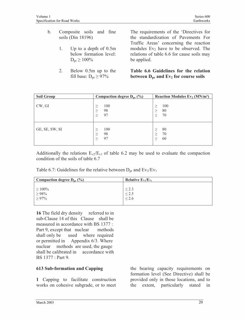
The requirements of the ‘Directives for the standardization of Pavements For Traffic Areas’ concerning the reaction modules Ev2 have to be observed. The relations of table 6.6 for cause soils may be applied. Table 6.6 Guidelines for the relation between Dpr and Ev2 for course soils
Soil Group Compaction degree Dpr (%) Reaction Modules Ev2 (MN/m²) CW, GI
≥ 100 ≥ 98 ≥ 97
≥ 100 ≥ 80 ≥ 70
GE, SE, SW, SI
≥ 100 ≥ 98 ≥ 97
≥ 80 ≥ 70 ≥ 60
Additionally the relations Ev2/Ev1 of table 6.2 may be used to evaluate the compaction condition of the soils of table 6.7 Table 6.7: Guidelines for the relative between Dpr and Ev2/Ev1 Compaction degree Dpr (%) Relative Ev2/Ev1 ≥ 100% ≥ 98% ≥ 97%
≤ 2.3 ≤ 2.5 ≤ 2.6
16 The field dry density referred to in sub-Clause 14 of this Clause shall be measured in accordance with BS 1377 : Part 9, except that nuclear methods shall only be used where required or permitted in Appendix 6/3. Where nuclear methods are used, the gauge shall be calibrated in accordance with BS 1377 : Part 9.
613 Sub-formation and Capping 1 Capping to facilitate construction works on cohesive subgrade, or to meet
the bearing capacity requirements on formation level (See Directive) shall be provided only in those locations, and to the extent, particularly stated in
Volume 1 Series 600 Specification for Road Works Earthworks
March 2003 21
Appendix 6/7 to be constructed with capping. It shall comply with this Clause and in addition, for stabilized capping, with Clauses 614, 615 and 643 as appropriate. 2 Capping shall be constructed with Class 6F1, 6F2, 6F3, 9A, 9B, 9D, 9E or 9F material as required or permitted in Appendix 6/7 and complying with Table 6/1. 3 Unless otherwise described in Appendix 6/7, capping shall either consist of one Class of capping material throughout its depth laid in one or more layers of compacted thickness complying with Clause 612, or be formed of not more than two elements of different capping materials. Each element shall be formed of one or more layers of the same capping material, each of compacted thickness complying with Clause 612. Class 9D or 9E stabilized capping material shall not be placed or constructed above Class 6F granular capping material. 4 Unless otherwise stated in Appendix 6/7, the subformation shall have the same longitudinal gradient, crossfall and surface level tolerances as the formation. 5 The Contractor shall limit any unprotected area of sub-formation, which is to receive capping to suit the output of the plant in use and the rate of deposition of capping. 6 No unprotected subformation, which is to receive capping, shall remain continuously exposed to rain causing degradation, nor be left uncovered overnight. 7 In cuttings the Contractor shall, as permitted or required in Appendix 6/7
carry out one of the following procedures: (i) for Class 6F1, 6F2 or 6F3 capping,
excavate below formation level to a depth to accept the capping, trim the surface to form the subformation and immediately compact with one pass of a smooth-wheeled roller having a mass per m width of roll not less than 2,100 kg or a vibratory roller having a mass per m width of roll not less than 700 kg or a vibrating plate compactor having a mass per m² of not less than 1,400 kg, and immediately deposit and compact above it a capping in Class 6F1, 6F2 or 6F3 material; or
(ii) for Class 9A, 9B,9D, 9E or 9F
capping material construct the capping by stabilizing the intact material, providing it complies with Class 6E, 6R 7E, 7F, 7G or 7I material requirements, immediately below formation to form Class 9A, 9B, 9D, 9E or 9F material, respectively; or
(iii) excavate below formation to
sufficient depth to enable stabilization of intact Class 6E, 6R, 7E, 7F, 7G or 7I material to be carried out, to produce Class 9A, 9B, 9D 9E or 9F material forming the lower element of the capping (after stabilization of this element, the capping shall be completed by depositing a further layer or layers of Class 6E, 6R 7E, 7F, 7G, or 7I material and stabilizing it to form Class 9A, 9B, 9D, 9E or 9F capping or depositing and compacting Class 6F1, 6F2 or 6F3

Volume 1 Series 600 Specification for Road Works Earthworks
March 2003 22
material to form the upper element of the capping); or
(iv) excavate to sub-formation level
and deposit material complying with Classes 6E, 6R, 7E, 7F, 7G, or 7I to be stabilized to form a capping of Class 9A, 9B, 9D, 9E or 9F layers. Where a stabilized layer is directly overlain by Class 6F1, 6F2 or 6F3 material the stabilized layer shall be compacted as for a sub-formation in 7 (i) above.
8 On embankments and other areas of fill the Contractor shall, as permitted or required in Appendix 6/7 carry out one of the following procedures: (i) complete the embankment to form
the subformation or remove any protection layer and trim the surface to form the subformation, and in both cases compact with one pass of a smooth-wheeled roller having a mass per m width of not less than 2,100 kg or a vibratory roller of not less than 700 kg per m width or a vibrating plate compactor having a mass per m² of not less than 1,400 kg, and immediately construct above it, in one or more layers, Class 6F1, 6F2 or 6F3 capping; or
(ii) construct the embankment to
sufficient height and carry out stabilization to form a capping of Class 9A, 9B, 9D, 9E or 9F material in one or more layers utilizing where appropriate any protection layer previously constructed; or
(iii) for multi-element capping, incorporating stabilized material, construct the embankment to sufficient height to carry out the work described in 8(ii) above and immediately construct above it one or more layers of Class 6F1, 6F2 or 6F3 capping.
Where a stabilized layer is directly overlain by Class 6F1, 6F2 or 6F3 material the stabilized layer shall be compacted as for a sub-formation in 8(i) above. 614 Cement Stabilization to Form Capping 1 Where capping is to consist of, either wholly or in part, cement stabilized material Class 9A or 9B this Clause shall apply to the construction of those parts which are stabilized with cement. 2 Material to be stabilized with cement shall be Class 6E or Class 7F materials all complying with Clause 601 and Table 6/1. Unless otherwise described in Appendix 6/7 cement shall be Portland cement complying with Clause 1001. 3 Class 6E or class 7F material to be stabilized shall have added to it, at any point, that quantity of cement measured as a percentage of its dry weight as determined on the demonstration area, to meet the required. Ev2 value in Appendix 6/1, subject to a minimum of 2% cement. 4 The appropriate quantity of cement shall be uniformly spread, by a suitable spreading machine, on top of the layer to be processed. Using a collecting tray and balance the Contractor shall check the
Volume 1 Series 600 Specification for Road Works Earthworks
March 2003 23
rate of spread of the machine once for every 500 m² of cement spread. 5 Unless indicated otherwise in Appendix 6/7, Class 6E or 7F material shall be stabilized in a single layer if its compacted thickness is 250 mm or less. If its compacted thickness is greater, the material shall be stabilized in layers not less than 130 mm and not more than 250 mm thick, including any cutting-in required by sub-Clause 9 of this Clause. 6 The Contractor shall not carry out cement stabilization when the shade temperature is below 3°C unless on a rising thermometer above 0°C. Cement stabilization shall not be carried out during periods of rain or when rain is imminent. When cement is spread on material likely to cause premature hydration, processing in accordance with sub-Clause 7 of this Clause shall follow immediately. 7 Unless indicated otherwise by Appendix 6/7, Class 6E or 7F material forming the layer to be stabilized shall be processed by pulverising and mixing in the cement by means of a sufficient number of passes of a suitable mobile stabilizing machine until 95% of the silt and clay fraction is reduced to particles or lumps passing a BS 28 mm sieve after dry sieving and the pulverisation complies with Table 6/1. 8 During processing, only sufficient water shall be available in the material to hydrate the cement and enable satisfactory mixing and compaction to be achieved. Any added water shall be through an integral spray-bar on the stabilizing machine.
9 The stabilizing machine shall be equipped with a device for controlling the depth of processing which shall be maintained at the correct setting at all times. An overlap of 150 mm shall be made between adjacent passes of the stabilizing machine. Where a subsequent layer of material is placed on a layer previously stabilized the tines or blades of the stabilizing machine shall be set so that they cut into the previously stabilized layer below by at least 20 mm. 10 Each layer of Class 9A or 9B processed material shall be compacted as soon as possible after the final pass of the stabilizing machine. Compaction shall be completed within 2 hours following the mixing of the cement into the material to be stabilized. Immediately before compaction Class 9B processed material shall have a Moisture Condition Value (MCV) of not greater than 12 nor less than the figure stated in Appendix 6/1 for Class 9B cement stabilized material, both as determined in accordance with Clause 632. Water shall be added if necessary in a uniform manner to enable this MCV requirement to be met. 11 The compaction of each layer of Class 9A or 9B material shall comply with Clause 612, Table 6/4 Method 6 or Method 7 respectively, except that if layers of Class 9A or 9B greater than 250 mm thickness are to be constructed, the number of passes of the compaction plant shall be determined from the results of a demonstration area as detailed in Appendix 6/7. 12 Class 9A or 9B materials shall be cured in accordance with Clause 1035. During periods when the air temperature is forecast to drop below 3°C or when
Volume 1 Series 600 Specification for Road Works Earthworks
March 2003 24
ground frost is forecast Class 9A or 9B material shall be protected, to prevent freezing, for a period of 7 days from the time of completion of compaction. Such protection shall be sealed to prevent the ingress of moisture. 13 Class 9A or 9B materials shall not have other material deposited or compacted above them until such time as the required Ev2 value in Appendix 6/1 has been achieved. The relaxation allowed in sub-Clause 617.2 shall not apply before this time. 615 Lime Stabilization to Form Capping 1 This Clause shall apply only to those capping materials which are to be stabilized with lime to form material Class 9D. 2 Material to be stabilized with lime shall be Class 7E material complying with Clause 601 and Table 6/1. 3 Lime for lime stabilization shall, as required in Appendix 6/7, be either quicklime or hydrated lime complying with BS 890. Quicklime shall when sieved have 100% passing a BS 10 mm sieve and at least 95% by mass passing a BS 5 mm sieve. 4 The Contractor shall make available to the Overseeing Organisation for each source of lime a report of a chemical analysis for ‘available lime’ made in accordance with sub-Clause 641.2. Such reports shall be made available to the Overseeing Organisation prior to the incorporation of lime in the Permanent Works at weekly or other intervals
defined in Appendix 6/7 during periods when lime stabilization is carried out. 5 Class 7E material to be stabilized shall have added to it, at any point, the percentage of its dry weight of lime, as determined on the demonstration area, to meet the required Ev2 value in Appendix 6/1, subject to a minimum of 2½% by weight of ‘available lime’ as a percentage of the dry weight of the Class 7E material. 6 Lime of quantity complying with sub-Clause 5 of this Clause shall be uniformly spread by a suitable spreading machine on top of the layer to be stabilized. Using a collecting tray and balance the Contractor shall check the rate of spread by weight, once for every 500 m² of lime spread or a different rate of testing for the rate of spread as described in Appendix 6/7. At the same time the Contractor shall collect samples of lime deposited on the tray and test them for available lime content in accordance with Clause 641. 7 Unless indicated otherwise in Appendix 6/7, the material shall be stabilized in a single layer if its compacted thickness is 250 mm or less. If its compacted thickness is greater, the material shall be stabilized in layers not less than 130 mm and not more than 250 mm thick, including any cutting-in required by sub-Clause 12 of this Clause. 8 Unless indicated otherwise in Appendix 6/7 lime stabilization shall not be carried out during periods of rain or when rain is imminent and when the shade temperature is not below 7°C. Only when the specified Ev2 value is attainable at a shade temperature less
Volume 1 Series 600 Specification for Road Works Earthworks
March 2003 25
than 7°C, may lime stabilization be carried out at such lower temperature. Lime stabilization shall be suspended if rainfall will have an adverse effect on the material being stabilized. The spreading of lime shall not be carried out in a manner or under conditions that will result in lime being blown from the site onto adjacent land or property. 9 Unless indicated otherwise in Appendix 6/7, the material forming the layers to be stabilized shall be processed by pulverising and mixing in the lime by means of sufficient number of passes of a suitable mobile stabilizing machine until 95% of the Class 9D processed material passes a BS 28 mm sieve after dry sieving and the pulverisation complies with Table 6/1. 10 During processing only sufficient water shall be available in the material to slake the quicklime (if used) and to enable satisfactory mixing and compaction to be achieved. Any added water shall be through an integral spray-bar on the stabilizing machine. 11 The layer shall receive at least two passes of the stabilising machine to pulverise and mix the lime and soil, after which the processing shall be interrupted by a period of not less than 24 hours and not greater than 72 hours, to enable the lime to react with the soil. Before this period commences the surface of the layer shall be sealed with one pass of a smooth wheeled roller having a mass per metre width of roll of not less than 2700 kg or a pneumatic tyred roller of not less than 1000 kg per wheel. At the end of this period the layer shall receive one further pass of the stabilizing machine or more if required to enable the material to comply with sub-Clauses 9 and 13 of
this Clause, adding water uniformly if necessary. 12 The stabilizing machine shall be equipped with a device for controlling the depth of processing which shall be maintained at the correct setting at all times. An overlap of 150 mm shall be made between adjacent passes of the stabilizing machine. Where a subsequent layer of material is placed on a layer previously stabilized the tines or blades of the stabilizing machine shall be set so that they cut into the previously stabilized layer below by at least 20 mm. 13 Each layer of Class 9D processed material shall be compacted as soon as possible after the final pass of the stabilizing machine. Immediately before compaction the processed material shall have a Moisture Condition Value (MCV) of not greater than nor less than the figures stated in Appendix 6/1, for Class 9D lime stabilized material, both as determined in accordance with Clause 632. 14 If there is a delay following the final pass and before commencement of compaction the surface shall be sealed by not less than 2 passes of a smooth-wheeled roller having a mass per metre width of not less than 2,700 kg or of a pneumatic tyred roller of not less than 1,000 kg mass per wheel. On recommencement and before compaction the layer shall be re-processed without the addition of lime, by a sufficient number of passes of the stabilising machine to meet the MCV requirements of sub-Clause 13 of this Clause adding water uniformly if necessary.

Volume 1 Series 600 Specification for Road Works Earthworks
March 2003 26
15 The compaction of each layer shall comply with Clause 612, Table 6/4 Method 7 except that if layers more than 250 mm thick are constructed the number of passes of the compaction plant shall be those determined from results obtained on a demonstration area as detailed in Appendix 6/7. 16 Class 9D material shall not have other material deposited or compacted above it until such time as the required Ev2 value ratio in Appendix 6/1 has been achieved. The relaxation allowed in sub-Clause 617.2 shall not apply before this time. 616 Preparation and Surface Treatment of Formation 1 The formation shall, after completion of any subgrade drainage, and immediately before laying subbase on areas of completed formation, have a surface level tolerance within ±20 mm or ±25 mm according to table 7.1 of clause 70, or other level of tolerance defined in Appendix 6/7 relative to its designed level after completion of the following operations as necessary: (i) Any protection layer shall be
removed and any soft or damaged areas shall be rectified by excavating them and replacing with acceptable material having the same characteristics and strength as the surrounding material. The surface of the formation shall be trimmed and immediately cleaned free from mud and slurry which shall be dealt with as unacceptable material Class U1.
(ii) The formation shall immediately be compacted, in addition to the compaction required for the fill. This additional compaction shall for this purpose be assumed to be as for a layer of 250 mm finished thickness compacted in compliance with Clause 612 and Table 6/4 Method 6 except for Class 3 materials where Method 4 shall be used. Immediately after the additional compaction the formation shall be trimmed to achieve the tolerances of this sub-Clause.
2 Where the tolerances in sub-Clause 1 of this Clause are exceeded, the Contractor shall determine the full extent of the area which is out of tolerance and shall make good the formation as follows: (i) if the surface is too high it shall be
re-trimmed and re-compacted in compliance with Clause 612 and sub-Clause 1 of this Clause;
(ii) if the surface is too low it shall be
corrected by the addition of acceptable material complying with Table 6/1 having characteristics and strength matching the overlaid material, deposited and compacted in compliance with Clause 608 and 612 and sub-Clause 1 of this Clause. In cohesive materials Classes 2 and 7, where this low surface is less than 150 mm below formation, material shall be removed to a depth of at least 150 mm below formation before the additional material is deposited and compacted.
Volume 1 Series 600 Specification for Road Works Earthworks
March 2003 27
3 After trimming, or re-trimming if necessary, the formation shall be rolled with one pass of a smooth-wheeled roller having a mass per metre width of roll not less than 2100 kg or, a vibratory roller having a mass per metre width of vibrating roll of not less than 700 kg or a vibrating plate compactor having a mass per m² under the base plate of not less than 1,400 kg. 4 Where required in Appendix 6/7 or where the tolerances in sub-Clause 1 of this Clause cannot be achieved in the preparation of formation in rock then one of the following shall be carried out so as to achieve the above tolerances: (i) the material shall be excavated
below formation to the depth described in Appendix 6/7. The excavated material shall be processed as described in Appendix 6/7 and re-deposited and compacted in compliance with Clauses 608 and 612 and Table 6/4 Method 6 in compacted layers not greater than 250 mm thick; or
(ii) where the rock surface is tabular it
shall be regulated by depositing and compacting cement bound material as described in Appendix 6/7, complying with the 1000 Series, or mix ST1 concrete.
5 The Contractor shall limit any areas of completed formation to suit the output of plant in use and the rate of deposition of sub-base. No formation of cohesive material Classes 2 and 7 shall remain continuously exposed to rain causing degradation or be left uncovered overnight.
6 The preparation of formation on existing sub-base material shall be completed as described in Appendix 6/7. 617 Use of Sub-formation or Formation by Construction Plant 1 Construction plant and other vehicular traffic (except that required for the construction of capping) shall not be operated on the sub-formation, unless adequate protection, if necessary in addition to any weather protection, is provided. 2 Construction plant and other vehicular traffic (except for that required for preparation of the formation in compliance with Clause 616) shall not be operated on the formation unless adequate protection, if necessary in addition to any weather protection is provided. 3 In addition to the requirements of sub-Clauses 1 and 2 of this Clause, the Contractor shall make available to the Overseeing Organisation his proposals for the protection of the sub-formation or formation in areas where they are within 300 mm of the existing ground level, after topsoil has been stripped, before using construction plant or other vehicular traffic at or above sub-formation or formation. 618 Topsoiling, Grass seeding and Turfing
Volume 1 Series 600 Specification for Road Works Earthworks
March 2003 28
1 Topsoiling shall be carried out using Class 5 material complying with Table 6/1. 2 Imported topsoil, Class 5B material, shall only be imported when required in Appendix 6/8 or when permitted or instructed by the Engineer. 3 When required in Appendix 6/8 topsoil shall not be excavated from stockpiles, whether on site or imported: (i) which have been exposed to a
cumulative rainfall exceeding 100 mm, or other figure stated in Appendix 6/8, over the preceding 28 days measured at a point detailed in Appendix 6/8; or
(ii) when heavy rain is falling; or (iii) with a tracked vehicle. Volume 1 home page 4 Topsoil shall: (i) be deposited and spread on the
areas, to the thicknesses described in Appendix 6/8, in layers not exceeding 150 mm. Each layer shall be firmed before spreading the next. The thickness shall be reduced where necessary to allow for any subsequent turfing required in Appendix 30/5 (it shall not be spread using a tracked vehicle, when so stipulated in Appendix 6/8);
(ii) have stones and other debris
removed and disposed off Site which have:
a. dimensions greater than 100
mm equivalent diameter,
unless otherwise permitted in Appendix 6/8; and
b. dimensions greater than 50
mm equivalent diameter which lie within 50 mm of the surface;
(iii) be graded to smooth contours,
eliminating all mounds and depressions where water may collect;
(iv) not have stones or other debris
protruding above the surface by more than 30 mm, and comply with the further requirements of Clauses 3004 and 3005.
5. The areas to be grassed shall receive one of the following treatments as described in Appendix 6/8: Treatment 1: topsoiled, fertilized and seeded Fertilizer and seed may, unless otherwise stated in Appendix 6/8 be applied by hydraulic mulch. Treatment II: Topsoiled, fertilized and turfed Treatment III: Left untopsolied but fertilized and seeded by hydraulic mulch. 6. Cutting slopes which are to receive Treatment I or II shall: be benched when required in Appendix 6/3 to retain topsoil unless otherwise stated in appendix 6/8 or directed by the Engineer, be harrowed to a depth of 50mm. Such harrowing shall be carried out, immediately prior to topsoiling, diagonally, at an angle

Volume 1 Series 600 Specification for Road Works Earthworks
March 2003 29
between 5° to 45° to the line of the to, measured on the plane of the slope. 7. Topsoil in treatment I and II shall: (i) be deposited and spread to the
thicknesses described in Appendix 6/8, which thickness shall be reduced where necessary to allow for any subsequent turfing required in Appendix 6/8 or permitted by the Engineer it shall not be spread using a tracked vehicle, when so stipulated in Appendix 6/8):
(ii) have stone and other debris
removed and disposed off site which have:
a) dimensions greater than
100mm equivalent diameter, unless otherwise permitted by the Engineer, and
b) dimensions greater than
50mm equivalent diameter which lie within 50mm of the surface.
(iii) not have stone or other debris
protruding above the saurface by moe than 30min and
(iv) immediately prior to sowing of
seed, including that applied by hydraulic mulch and before laying of turf have:
a) its upper 50mm thickness
reduced to a fine tilth by use of a chain harrow or other plant producing a similar fine tilth; and
b) fertilizer complying with sub
clause 13 of this clause
evenly distributed and raked in, at a rate not less than 75g per m² or other rate required in Appendix 6/8 or agreed with the Engineer. If hydraulic mulch seeding is used such fertilizer may be incorporated in the mulch and no raking in is necessary.
8. Seeding in Treatment 1 shall: (i) employ a mixture of seed
complying with sub-clause 14 of this clause and
(ii) be carried out by evenly
distributing such seed at a rate of not less than 20g/m² for side slopes of both embankments and cuttings and not less than 10g/m² elsewhere or other rate required in Appendix 6/8 or agreed by the Engineer; and
(iii) by immediately followed by
lightly ranking, by use of a chain horrow or other plant approved by the Engineer, the surface of the topsoil to cover the seeds except that no ranking is required following hydraulic mulch seeding.
9.Turf in Treatment II shall: (i) be laid in the areas described in
Appendix 6/8 or in other area as permitted by the Engineer or
(ii) consist of class 5C imported turf
complying with table 6/1 or when permitted by the Engineer; turf arising on Site and required to be excavated as Class 5 A material; and

Volume 1 Series 600 Specification for Road Works Earthworks
March 2003 30
(iii) be laid well bonded and lightly
tamped and when on slope be laid diagonally; and
(iv) where required in Appendix 6/8 be
retained in position by methods described therein; and
(v) be regularly watered as necessary
during prolonged dry weather 10 Hydraulic mulch seeding shall: (i) be applied by a process and consist
of a mulch approved by the Engineer; and
(ii) where required in Appendix 6/8
have as part of those mulch, glass fiber or other material to form a retaining agent during establishment of swarm growth; and
(iii) for treatment III have as part of the
mulch additional additives for promotion of grass growth on the material to be grassed.
11 Except on areas not required to be mown or to be mown three times all as described in Appendix 6/8, areas of grass resulting from treatment I to III shall be mown twice to leave a nominal 75mm height. The first mowing shall be carried out ounce the grass has reached f height of between 100mm and 150mm, the second when it has regrown to between 150mm and 200mm. The plant used for mowing shall comply with any
requirements in Appendix 6/8. All areas shall unless permitted otherwise by he Engineer, be left clear of glass cutting following each mowing, by raking or other method approved by the Engineer and arising disposed of site. 12. At the times (Which may include times within the period of maintenance) and within the area instructed by the Engineer, a selective herbicide, approved by the engineer, especially formulated for the prediction of docks, thistles, ragwort and other pernicious agricultural weeds shall be applied by spot treatment spray to such plants individually; the use of spray boom will not be permitted. 13 Fertilizer, including where approved by the Engineer that incorporated in hydraulic mulch, shall consist of a compound containing not less than 10% Nitrogen, 15% Phosphoric Acid and 10& Potash and samples shall be submitted to the Engineer for approval prior to its use in the Permanent works. 14. Grass seed, including where approved by the Engineer, that incorporated in a hydraulic mulch, shall be tested mixture and certificates of germination and purity shall be provided before sowing, together with the names of the varieties used in the mixture. Unless otherwise required in Appendix 6/8 or agreed by the Engineer, this shall contain the seeds listed in Table 6/6 to the proportions therein.

Volume 1 Series 600 Specification for Road Works Earthworks
March 2003 31
Table 6/5: records and Reports – Information Required Ground Treatment
In situ Testing
For each column/area treated: Date Contract title Area identification Unique Grid location Ground Level at Commencement Material used Approximate column diameter Depth of penetration of each compaction point Vibrator power compaction during operation Jetting pressure (where applicable) Duration of penetration Duration of compaction Obstructions and delays Number of tests carried out
For each area tested: Date Contract Title Area identification Test position, co-ordinates and level Method of test used All information required by appropriate British Standard test procedure
Table 6/6: Grass Seed Mixture per 50kg Perennial Rye Grass Strong Creeping Red Fescue Hard Fescue Smooth-stalked Meadow Grass Highland Brown top Bent Huia White Clover
Kg 12.5 10.0 15.0 5.0 5.0 2.5
% 25 20 30 10 10 5
619 Earthwork Environmental Bunds 1 Earthwork environmental bunds shall be constructed in the locations described in Appendix 6/9 with fill materials complying with the requirements therein and Clause 601 and Table 6/1. Deposition shall be in accordance with Clause 608 and compaction with the requirements of Table 6/1 unless otherwise described in Appendix 6/9 or the requirements of sub- Clauses 2 or 3 of this Clause apply. 2 Earthwork environmental bunds formed of reinforced or anchored earth
shall be constructed in compliance with Clauses 2502 and 622. 3 Earthwork environmental bunds formed of strengthened embankments shall be constructed in accordance with Clause 621. 4 Where required in Appendix 6/9 earthwork environmental bunds shall be top soiled and seeded, or topsoiled and turfed, all in accordance with Clause 618. 620 Landscape Areas and Screening Mounds

Volume 1 Series 600 Specification for Road Works Earthworks
March 2003 32
1 Landscape areas and screening mounds shall be constructed in the locations shown in Appendix 6/9 with Class 4 material as described therein and complying with Table 6/1. 2 Unless method compaction to Clause 612 is required in Appendix 6/9 the degree of compaction of Class 4 material shall be sufficient to remove large voids and to produce a coherent mass whilst preventing over-compaction and any build up of excess pore pressures. 3 Following completion of filling of landscape areas, and screening mounds Class 4 material shall where required in Appendix 6/9, be shaped as described therein. 4 Class 4 material shall be deposited in landscape areas or screening mounds after any adjoining embankment or other area of fill has been completed. Where permitted in Appendix 6/9 and provided the adjoining embankment or other area of fill is always kept at least 1 m higher than the landscape area fill, construction of such landscape area may proceed until completion. 5 Landscape areas and screening mounds shall be topsoiled and seeded or turfed in accordance with Clause 618 to the requirements of Appendix 6/9. 621 Strengthened Embankments 1 Strengthened embankments shall be constructed in the locations and to the details described in Appendix 6/9 with fill materials and strengthening materials described therein. 622 Earthworks for Reinforced Earth and Anchored Earth Structures
1 The construction of earthworks for reinforced soil and anchored earth structures together with assembly and erection of reinforcing and anchor elements and associated components shall be in compliance with this Clause and Clause 2502. 2 Excavation shall be carried out in compliance with Clause 604. 3 Fill for reinforced soil structures shall, except for their associated drainage layers, be of Class 6I, 6J, 7C or 7D selected material complying with Table 6/1 as permitted in Appendix 6/1 together with any other additional requirements therein. Volume 1 home page 4 Fill for anchored earth structures shall, except for their associated drainage layers, be of 6I or 6J selected material complying with Table 6/1 as permitted in Appendix 6/1 together with any other additional requirements therein. 5 Drainage layers to reinforced soil and anchored earth structures shall be one of the following as appropriate: (i) Class 6H material complying with
Table 6/1 and Appendix 6/1. (ii) Type B filter drain material
complying with Clause 505 for use only in horizontal drainage layers. Vertical layers of drainage layer material shall be brought up at the same rate as the adjoining fill material without mixing or contamination.
6 In addition to the requirements of sub-Clauses 7 and 8 of this Clause, fill for reinforced earth and anchored earth

Volume 1 Series 600 Specification for Road Works Earthworks
March 2003 33
structures shall be deposited and compacted in compliance with Clauses 608 and 612 and Table 6/1. Drainage layer material other than Class 6H shall be deposited in accordance with Clause 608 and compacted as described in Appendix 6/3. 7 Reinforced earth and anchored earth structures shall have: (i) the deposition and compaction
carried out so that all layers of reinforcing and anchor elements are fixed at the required levels on top of compacted fill;
(ii) the deposition, spreading, leveling
and compaction of the fill carried out generally in a direction parallel to the facing and executed in stages to alternate with the placing and fixing of the reinforcing and anchor elements and the facing elements;
(iii) the reinforcing and anchor
elements kept as free as possible from damage or displacement during deposition, spreading, leveling and compaction of the fill (also the programme of filling shall be arranged so that no machines or vehicles run on the reinforcing or anchor elements);
(iv) all construction plant, and all other
vehicles, having a mass exceeding 1,000 kg, kept at least 2 m away from the back of the facing;
(v) within 2 m of the back of the
facing, the plant used for compacting the fill restricted to the following items as described in
sub- Clause 612.10 and listed in Table 6/4:
a. vibratory roller having a
mass per metre width of roll not exceeding 1,300 kg with a total mass not exceeding 1,000 kg;
b. vibrating plate compactor
having a mass not exceeding 1,000 kg;
c. vibro tamper having a mass
not exceeding 75 kg;
(vi) at the Contractor’s option, the reinforced earth and anchored earth fill beyond the 2 m zone referred to in (v) above, raised in thicker layers than within the 2 m zone, providing this is compatible with the arrangement of the reinforcing and anchor elements and the difference in compacted level does not exceed 300 mm;
(vii) during construction of the
reinforced earth or anchored earth structure the retained fill at the rear of the structure, as defined in sub- Clause 8 of this Clause, maintained at the same level as the adjoining reinforced earth or anchored earth fill;
(viii) if the retained material at the rear
of the reinforced soil or anchored earth structure, as defined in sub-Clause 8 of this Clause, is an existing earthwork or natural slope which requires supporting by temporary shoring, this shoring shall be removed progressively as the work proceeds to prevent the formation of voids.

Volume 1 Series 600 Specification for Road Works Earthworks
March 2003 34
8 The rear of the reinforced soil or anchored earth structure is the position coinciding with the ends of the reinforcing or anchor elements furthest from the facing units. 623 Earthworks for Corrugated Steel Buried Structures 1 The construction of earthworks for corrugated steel buried structures together with assembly and erection of their components shall be in compliance with this Clause and Clause 2501. 2 Excavation shall be carried out in compliance with Clause 604 and any additional requirements given in Appendix 6/3. Volume 1 home page 3 Fill for corrugated steel buried structures shall be of the following selected granular materials complying with Table 6/1: (i) Lower bedding material Class 6K. (ii) Upper bedding material Class 6L. (iii) Surround material Class 6M and
the overlying fill shall be one of the following:
(iv) Well graded, uniformly graded or
coarse, granular material Class 6Q. (v) Wet, dry, stony or silty cohesive
material. 4 In addition to the requirements of sub-Clauses 5 to 14 of this Clause, Class 6K, 6L and 6M materials shall be deposited in compliance with Clause 608 and shall (except for Class 6L upper bedding
material which shall be uncompacted) be end-product compacted in compliance with Clause 612 and Table 6/1, except that the compacted layers shall not exceed 150 mm thickness. The compaction and testing requirements for Class 6K lower bedding and Class 6M surround materials shall also comply with any additional requirements given in Appendix 6/3. 5 Class 6K lower bedding material shall have its top surfaced shaped during compaction to match the steel structure profile. A uniform layer of uncompacted Class 6L upper bedding material, shall be deposited, before the placing of any part of the steel structure, over the whole width of the shaped lower bedding material and shall be of sufficient depth to fill the corrugations of the underside of the structure. 6 Class 6M surround material shall be used for filling all excavations above the bedding, except those in hard material for which Class 6K lower bedding material shall be used throughout. Additional requirements for making good are given in Clause 604. 7 Class 6M surround material shall be deposited and compacted uniformly on either side of the structure. The maximum difference in fill level on opposite sides of the structure shall be no more than 250mm at all times unless otherwise permitted in Appendix 6/3. 8 Class 6M surround material shall be deposited and compacted in accordance with sub-Clause 4 of this Clause, above the concrete foundations of arch-profile corrugated steel buried structures.

Volume 1 Series 600 Specification for Road Works Earthworks
March 2003 35
9 Class 6M surround material under the structure shall be well compacted by hand using a suitably sized pole or length of rectangular timber between the corrugations, or by another suitable method. 10 Plant for compaction of Class 6M surround material within 1 m of either side of the structure and up to a height of 1 m, or one fifth of the span if greater, above the crown, shall be restricted to the following items, as described in sub-Clause 612.10 and listed in Table 6/4: (i) vibratory rollers having a mass per
metre width of roll not exceeding 750 kg;
(ii) vibrating plate compactors having
mass not exceeding 750 kg; (iii) vibro-tampers. 11 Fill placed above the level of the crown of the structure, including Class 6M surround material, shall be deposited, spread and compacted in such a manner that any out of balance forces transmitted to the culvert are kept to a minimum. This will require that trafficking by construction plant is not all in one direction and that the compacted surface of the fill is kept as near horizontal as practicable. 12 During all operations of filling, compaction, road pavement construction and of any other traffic movements which affect the shape of the structure, the changes in the horizontal and vertical diameters of the structure shall not exceed ± 5% for circular structures and ± 2% for structures of other cross-sections. The longitudinal straightness over any 10 m length of the structure
shall not deviate by more than 25 mm, and the rotational displacement in any 10 m length of structure shall not be greater than 25 mm. 13 Only that compaction plant described in sub-Clause 10 of this Clause, shall be used in the vicinity of the structure unless the depth of compacted Class 6M surround material placed above the crown of the structure is more than 1 m, or one fifth of the span, whichever is the greater. The structure shall not be subjected to a surcharge greater than the depth of fill required in the Contract and permitted depth of any protection layer given in Appendix 6/3. 14 No material shall be placed by tipping either onto the structure or within a distance on either side of the structure of 2 m or half the span of the structure, whichever is the greater. 15 Method compaction shall be used for the overlying fill (Classes 6Q and 7H) according to Clause 612; the method used being that for the corresponding generalfill in Table 6/1. Volume 1 hom 624 Ground Anchorages 1 The Contractor shall design the ground anchorages required as part of the Permanent Works and listed in Appendix 1/11, in accordance with the design requirements described in Appendix 6/10. The ground anchorages shall be installed and where required in Appendix 6/10 proof loaded, in accordance with the requirements therein. 2 Ground anchorages not forming part of the Permanent Works will only be

Volume 1 Series 600 Specification for Road Works Earthworks
March 2003 36
permitted where such anchorage will not affect the Permanent Works. 625 Crib Walling 1 The Contractor shall design the crib walling listed in Appendix 1/10 in accordance with the design specification and procedures in Appendix 6/10 and Standard BD 68. 626 Gabions 1 Gabions shall be constructed in compliance with this Clause and with any additional requirements in Appendix 6/10. 2 Gabion units shall be assembled in accordance with the manufacturer’s instructions and shall be sufficiently filled with Class 6G material complying with Table 6/1 and any other requirements in Appendix 6/1, with an allowance for consolidation of fill, so as to minimize distortion during construction. Gabion units shall, where appropriate, be maintained square and with vertical sides during filling. Internal tie wires shall be inserted and units shall be tensioned in accordance with the manufacturer’s instructions. Gabion units shall be constructed so as to maintain tightness of mesh and shall be laced securely with wire, complying with sub-Clause 3(i) of this Clause. 3 The gabion mesh shall be one of the following unless otherwise described in Appendix 6/10: (i) A mesh manufactured from wire
complying with BS 1052 having a
minimum core diameter of 2.0 mm, unless otherwise described in Appendix 6/10.
(ii) A geomesh, being a grid of plastic
material suitable for use in earthworks, having the properties described in Appendix 6/10.
4 All wire shall be galvanized in compliance with BS 443 and be coated with a minimum thickness of 0.55 mm of PVC for extruded coatings and 0.25 mm of PVC for bonded coatings. The PVC shall be capable of resisting the effects of immersion in sea water, exposure to ultra violet light and abrasion, when tested for a period not less than 3000 hours in accordance with BS 2782 : Part 5 : Method 540B (ISO 4892). 5 The size of mesh openings and grading of fill shall be as described in Appendix 6/10, but the maximum size of fill material shall not exceed two thirds of the minimum dimension of the gabion compartment or 200 mm whichever is smaller and the minimum size of the fill, unless otherwise stated in Appendix 6/10, shall be not less than the size of the mesh opening. 6 Mechanical equipment may only be used for filling gabion units provided that the results are equivalent to filling by hand. 627 Swallow Holes and Other Naturally Occurring Cavities

Volume 1 Series 600 Specification for Road Works Earthworks
March 2003 37
1 Infilled swallow holes and other naturally occurring cavities shall where required in Appendix 6/11 be excavated, filled and capped as described in Appendix 6/11. 2 Open swallow holes and other shallow cavities shall where required in Appendix 6/11 be flushed, cleared of rubbish where to do so would not endanger operatives, and filled and capped as described in Appendix 6/11. 628 Disused Mine Workings 1 Disused mine workings shall, where required in Appendix 6/11 be investigated, inspected, monitored, cleared, flushed, filled, capped or have any other treatment carried out, all as described in Appendix 6/11. 629 Instrumentation and Monitoring 1 Instrumentation, other than that required in compliance with Clause 607, shall be as described in Appendix 6/12 and shall be installed in the locations shown therein. 2 Monitoring of instrumentation shall be carried out as required in Appendix 6/12 and the results supplied to the Overseeing Organisation as required therein. Volume 1 ho 630 Ground Improvement
Dynamic Compaction 1 Dynamic compaction, carried out to either method or end-product as required in Appendix 6/13 and achieved by dropping a free-falling heavy mass (pounder) a number of times at pre-determined spacing on the surface of the ground or fill, shall be applied to the areas described in Appendix 6/13. 2 Dynamic compaction shall be completed before the commencement of construction of any Permanent Works, or work on the placement or diversion of Statutory Undertaker’s equipment, within that part of the Site defined in Appendix 6/13 which contains the area to be dynamically compacted. 3 The Contractor shall ensure that no damage or injury is caused to persons or property on or off the Site as a result of the dynamic compaction. Vibrated Stone Columns 4 Vibrated stone columns in existing natural soils or fill by vibro replacement or vibro displacement shall be formed in the manner and in the areas described in Appendix 6/13. 5 Unless otherwise described in Appendix 6/13, materials shall comply with the Series 600 and the Series 800 as appropriate. 6 The Contractor shall report immediately to the Overseeing Organisation any circumstance which indicates that in the Contractor’s opinion the ground conditions differ from those expected from his interpretation of the ground investigation reports.

Volume 1 Series 600 Specification for Road Works Earthworks
March 2003 38
7 Columns shall be installed as shown on the Drawings and within the permitted tolerances stated in Appendix 6/13. Materials 8 The material used to form the columns shall be clean, hard, inert material and shall be sand, crushed rock, crushed hardcore or crushed concrete. The material shall be appropriate to the ground conditions in which the stone columns are formed and its use shall not be detrimental to any other work on site. The material shall be nominally single sized within the range 20 mm to 75 mm or a graded material complying with Clause 804 (granular sub-base type 2) except the material passing the BS 425ìm sieve shall be non-plastic when tested in accordance with BS1377: Part 2. Testing of Ground Treatment 9 Testing of treated ground shall be undertaken for control purposes during the treatment and on completion of the ground treatment. The performance criteria for treated ground are given in Appendix 6/13. 10 Improvement in treated ground shall be measured in accordance with the criteria stated in Appendix 6/13. Types of Test 11 The following tests or alternatives permitted in Appendix 6/13 shall be carried out at the positions and frequency given in Appendix 6/13. Plate tests
12 Plate bearing tests are loading tests carried out using a plate on treated ground. The test is described in BS 1377 : Part 9 : 1990 Method 4.1. Zone Tests 13 Zone tests are loading tests carried out with a slab, intended to test bearing pressure over a wider and deeper zone than in the plate tests. The test is described in BS 1377: Part 9: 1990 Method 4.2. Penetration Tests 14 In granular soils the static cone (Dutch cone) penetration test, the standard penetration test (SPT) or dynamic cone penetration tests shall be employed as described in Appendix 6/13. Trial Areas 15 Trial areas are to be treated and tested where required in Appendix 6/13. Trial areas, which meet the performance requirements, may form part of the Permanent Works. 16 Equipment and materials used in trial areas shall be identical to those proposed for the Permanent Works. 17 Testing in trial areas shall be carried out as given in Appendix 6/13. 18 Detailed reports shall be prepared for all testing as defined in Table 6/6. Records and Reports

Volume 1 Series 600 Specification for Road Works Earthworks
March 2003 39
19 Complete records of plant, equipment and materials shall be maintained during all ground treatment operations. 20 Records shall be made available to the Overseeing Organisation including all information identified in Table 6/6 and any other information required by Appendix 6/13. All records pertaining to a particular day’s operations shall be made available to the Overseeing Organisation at the start of the following day’s operations. Other Methods 21 Other methods of ground improvement shall be carried out where required in Appendix 6/13 and as described therein. 631 Earthworks Materials Tests 1 Unless otherwise described in the Contract sampling and testing of earthworks materials shall be carried out in accordance with BS 1377: Part 1 to Part 9 inclusive. 632 Determination of Moisture Condition Value (MCV) of Earthworks Materials 1 Where the Moisture Condition Value (MCV) is to be determined, the determination shall be carried out in accordance with BS 1377: Part 4. 2 The determination of the MCV/moisture content relation in accordance with BS 1377: Part 4 shall be carried out when required in Appendix 6/1.
3 Where permitted in Appendix 6/1 the rapid assessment procedure for material acceptability also given in BS 1377 : Part 4 may be used. 633 Determination of Undrained Shear Strength of Remolded Cohesive Material 1 Where required in Appendix 6/1, the undrained shear strength of cohesive soil under total stress conditions shall be determined from triaxial compression tests performed on remolded specimens and tested under conditions where the lateral pressure is maintained constant and there is no change in total water content of the specimens. Unless otherwise required in Appendix 6/1, the tests shall be in accordance with BS 1377 : Part 7 and the additional requirements of sub-Clauses 2 to 4 of this Clause. 2 The specimens shall be prepared in accordance with BS 1377 : Part 7 using remoulded material compacted into a split mould of nominal diameter 100 mm and nominal height 200 mm. The soil shall be at its natural moisture content and compacted in accordance with BS 1377: Part 1 using the 2.5 kg rammer method described in BS 1377 : Part 4. 3 The specimens shall be tested at an operating cell pressure of 200 ± 10 kN/m² and an axial strain rate of 1% per minute. Where Appendix 6/1 requires c and φ to be determined, the test shall be
Volume 1 Series 600 Specification for Road Works Earthworks
March 2003 40
modified to enable Mohr circles to be plotted and φ reported. 4 Where stated and described in Appendix 6/1, other tests may be used during construction to supplement the test described above, provided the results have been correlated to ensure compatibility. 634 Not Used 635 10% Fines Value and Other Tests for Particle Soundness 10% Fines Value (TFV) 1 The 10% fines value shall be the value determined in accordance with BS 812: Part 111 with samples tested in a soaked condition. Other Tests for Particle Soundness 2 Where Appendix 6/1 requires magnesium sulfate soundness tests to be carried out, they shall be carried out in accordance with BS 812 : Part 121. Where Appendix 6/1 requires slake durability, point load or other tests for soundness to be carried out, they shall be carried out in accordance with the procedures given therein. 636 Determination of Effective Angle of Internal Friction (φ) and Effective Cohesion (c) of Earthworks Materials 1 The effective angle of internal friction φ effective cohesion shall be determined by shear box or triaxial tests as required in Table 6/1 and Appendix 6/1. Unless
otherwise required in Appendix 6/1, the tests shall be in accordance with the requirements in sub-Clauses 2 to 6 of this Clause. Shear Box Tests 2 For Classes 6N, 6P, 6I and 6J granular materials, the tests shall be carried out in accordance with BS 1377 : Part 7 and the following: (iii) The plan size of the shear box shall
be nominally 300 mm square. (iv) Three samples shall be tested, each
sample occupying the full depth of the shear box and shall be compacted at the optimum moisture. content to a dry density of 92% ± 2% of the maximum dry density determined in accordance with BS 1377 : Part 4 using the vibrating hammer method. The samples shall not be immersed in water.
(v) Each of the samples shall be
subjected to a different normal stress equal to the maximum vertical pressure in the fill at the base, quarter height and mid-height of the structure respectively. Each of the samples shall be sheared in a single stage test within one hour of compaction and the rate of shearing shall be such that no pore water pressure is generated.
(vi) The values of φ reported shall be
those corresponding to the maximum strength envelope.
3 For Classes 7A, 7C and 7D cohesive materials, the tests shall be carried out in

Volume 1 Series 600 Specification for Road Works Earthworks
March 2003 41
accordance with BS 1377 : Part 7 and the following: (i) The shear boxes shall be nominally
300 mm square and nominally 60 mm square.
(ii) For the initial determination of fill
properties three samples shall be tested in each size of shear box. The samples shall occupy the full depth of the shear box and shall be compacted at the optimum moisture content to a dry density of 92% ± 2% of the maximum dry density determined in accordance with BS 1377 : Part 4 using the 4.5 kg rammer method. To allow the samples to soften, the shear box assembly shall then be immersed in water for a minimum period of 24 hours.
(iii) Each of the three samples in a set
shall be subjected to a different effective normal stress equal to the maximum vertical pressure in the fill at the base, quarter height and mid-height of the structure respectively. Normal stresses shall be applied to the softened sample for a minimum period of 24 hours prior to shearing in a single stage test. The rate of shearing shall be such that no pore water pressure is generated.
(iv) The values of cand reported shall
be those corresponding to the maximum strength envelope.
(v) The test results obtained using the
300 mm square box shall be taken as the properties of the fill. The initial test results obtained using the 60 mm square box shall be
used for the subsequent quality control of the fill.
Triaxial Tests 4 Where Class 7A cohesive fill to structures is to be tested by a consolidated drained triaxial test, the test shall be in accordance with BS 1377 : Part 8 using the sample size and preparation procedure in Clause 633 and the requirements of Appendix 6/1. 637 Determination of Resistivity (rs) to Assess Corrosivity of Soil, Rock or Earthworks Materials Method of Test 1 Where the resistivity of the ground or of material to be used in the Permanent Works is required to be determined, this shall be obtained by in situ tests as described in sub-Clause 2 of this Clause or, when required in Appendix 6/1, by laboratory tests on samples in accordance with BS 1377 : Part 3. In Situ Resistivity Tests 2 In situ resistivity shall be determined at the site of the structure or the cutting or the proposed borrow pit or on stockpiles in accordance with BS 1377 : Part 9 and the requirements of Appendix 6/1. 3 Details of the area and volume of material to be tested shall be made available to the Overseeing Organisation together with the arrangement of electrodes in each test. The Overseeing Organisation shall be given notice of the date, time and location of each test.
Volume 1 Series 600 Specification for Road Works Earthworks
March 2003 42
4 At any test location, at each selected depth, two measurements shall be made such that the electrode alignment for the second measurement is approximately at right angles to the electrode alignment for the first measurement. 5 At any test location, the first selected depth shall be no more than 1.5 m below the ground surface or no more than 1.5 m below the upper surface of the material to be tested, whichever is appropriate. Following the measurements at the first selected depth, further measurements shall be made at selected depths increasing by approximately 2 m each time until measurements have been carried out on the full depth of ground or material to be tested. 6 Where the depth of material to be tested is too great to be tested from the surface within the confines of the Site, the Contractor shall undertake all necessary arrangements for testing such material, including subsequent tests which may be required at a lower level following excavation. Details of his arrangements shall be made available to the Overseeing Organisation. 638 Determination of Redox Potential (Eh) to Assess Corrosivity of Earthworks Materials for Reinforced Soil and Anchored Earth Structures Method of Test 1 Where the redox potential of material to be incorporated into reinforced earth or anchored earth structures is required to be determined, this shall be obtained by in situ tests as described in sub-Clauses 2 to 6 of this Clause or, when
required in Appendix 6/1, by laboratory tests on samples in accordance with BS 1377: Part 3. In Situ Redox Potential Tests 2 In situ redox potential shall be determined in undisturbed ground at the site of the cutting or the proposed borrow pit or on stockpiles in accordance with BS 1377 : Part 9 and the requirements of Appendix 6/1. 3 Details of the area and volume of material to be tested shall be made available to the Overseeing Organisation together with the locations of the test pits. 4 The Overseeing Organisation shall be given notice of the date, time and location of each test. 5 At each test location the tests shall be carried out in a test pit not less than 600 mm square in plan excavated to a depth given in Appendix 6/1. 6 At each test location, a sample shall be taken from the base of the excavation and kept in a hermetically sealed container for determining the pH value of the fill which shall be obtained in accordance with BS 1377 : Part 3.

Volume 1 Series 600 Specification for Road Works Earthworks
March 2003 43
639 Determination of Coefficient of Friction and Adhesion Between Fill and Reinforcing Elements or Anchor Elements for Reinforced Soil and Anchored Earth Structures Reinforcing Elements 1 The coefficient of friction and the adhesion shall be determined by tests carried out in a 300 mm size shear box with the element material fixed at the top of the lower half of the box and the fill sample occupying the top half only. 2 The test shall be carried out following the procedure given in Clause 636 for the determination of the effective angle of internal friction and effective cohesion of earthworks materials except that: (i) The apparatus shall in addition
include a steel block fitting closely inside the lower half of the shear box and equal in height to it less the thickness of the reinforcing element material. (The flat toothed grid fitting the bottom of the shear box is not required).
(ii) The preparation of test specimens
shall be as follows: Element material shall be cut to fit the interior plan shape of the shear box using a sufficient number of strips of such material abutting to completely fill the interior plan area without overlap. They shall be firmly fixed to the top of the steel block so that the top face of the material is flush with the top edge of the lower half of the box and aligned so that shearing occurs in a direction parallel to the longitudinal axis of a reinforcing element.
A sample of the fill material to be used in the Permanent Works, of sufficient size to carry out the tests, and within the range of moisture contents permitted in Table 6/1 for such material, shall be sieved to obtain a test sample passing the 20 mm BS sieve, of sufficient quantity after compaction to fill the top half of the shear box. The top and bottom of the shear box shall be fixed together and the test sample of the sieved fill materials immediately placed and compacted in the top half of the box as described in Clause 636. 3 The value of the coefficient of friction between the fill and the reinforcing element shall be obtained by plotting the values of peak shear stress, obtained in the tests, against applied normal stress and by measuring the slope of the resulting straight line graph. The adhesion between the fill and the reinforcement shall be obtained by taking the shear stress corresponding with zero normal stress. 4 The following additional information shall be recorded for each test: (i) Normal stress applied (kN/m²). (ii) Peak shear stress (kN/m²). (iii) Strain at peak shear stress (%). (iv) Moisture content of fill after test
(Classes 7C and 7D). Anchor Elements 5 Where required in Appendix 6/1, tests shall be carried out as described therein to assess the interaction between the fill and the element.

Volume 1 Series 600 Specification for Road Works Earthworks
March 2003 44
640 Determination of Permeability of Earthworks Materials 1 Where required in Table 6/1 or Appendix 6/1 the permeability of earthworks materials shall be determined as described in Appendix 6/1. 641 Determination of Available Lime Content of Lime for Lime Stabilised Capping 1 The available lime content of lime for lime or lime and cement stabilised capping to be determined on Site shall be carried out as described in BS 6463: Part 1 except that the sample increments shall be taken from the collecting tray used to check the rate of spread at intervals of one increment per 500 m. 2 The available lime content shall be determined as calcium oxide in accordance with BS 6463: Part 2, Method 20, and the results reported as: Available lime (as CaO) = ......% by mass. 642 Determination of the Constrained Soil Modulus (M*) of Earthworks Materials for Corrugated Steel Buried structures General 1 When required in Appendix 6/1, the constrained soil modulus M* shall be determined by one of the following methods: (i) From plate loading tests in
accordance with BS 1377: Part 9.
(ii) From the results of Standard Penetration resistance tests (SPT) on non-cohesive materials in accordance with BS 1377: Part 9.
(iii) From the values of the coefficient
of volume compressibility (Mv) from one-dimensional consolidation tests on undisturbed soil specimens of cohesive materials, in accordance with BS 1377: Part 5.
Plate Loading Tests 2 When testing compacted granular fill materials the test surface shall be prepared by either: (i) removing the surface layer
carefully using hand tools to perform the test at a depth of 100 mm below the surface; or
(ii) compacting the surface, after the
required compaction has been applied, with two additional passes with no vibration to remove the overstressing in the surface layer. If necessary, the plate shall be bedded onto the fill using a small quantity of dry sand to remove any slight unevenness of the surface of the fill. The field dry density and moisture content shall be determined at the position of each plate loading test in accordance with Clause 612 and BS 1377 : Part 2 or equivalent, respectively.
3 When using the plate loading test to determine M* of the material existing on site a smooth surface shall be prepared by careful hand excavation and the plate bedded onto the soil using either sand or quick setting gypsum plaster depending
Volume 1 Series 600 Specification for Road Works Earthworks
March 2003 45
on whether the soil is granular or cohesive. 4 The loading test shall be carried out under a series of maintained loads. The maximum load should be such that the average pressure applied to the plate is in excess of 350 kN/m². The elastic modulus Es shall be determined as the secant modulus between average pressures applied to the plate of 150 and 350 kN/m² in the first load cycle. A value of Poisson’s ratio of 0.3 shall be assumed. A second load cycle testing shall also be conducted and the results of this test compared with the first load cycle. Generally a maximum load of 500KN/m² will be applied and the elastic modulus determined between pressures of 0.3 x maximum load and 0.7 x maximum load: E= 1.5 x 0.3m x ∆T ∆S It is preferred to determine Ev by a polynom. 5 The constrained soil modulus M* shall be determined from the elastic modulus Ev using the equation: (1 - v)Ev M* = ___________________ (N/mm²) (1 + v)(1 - 2v) where v = Poisson’s ratio to be taken as 0.3 and Es = Elastic modulus of the soil (N/mm²) Standard Penetration resistance Tests 6 The constrained soil modulus M* of non-cohesive materials existing on site
shall be determined from the relationship: 0.39N1.4 M* = ____________ (N/mm²) γm Where N = uncorrected SPT value and m = 1.3 One-dimensional Consolidation Tests 7 The constrained soil modulus M* of undrained cohesive materials existing on site shall be determined from the formula: 1 M* = ______ (N/mm²) mv where mv (mm²/N) is the coefficient of volume compressibility The value of mv to be used in the formula is that calculated from the test results for the loading increment in the consolidation test corresponding to the in situ effective overburden pressure at the level of the crown of the structure. Number of Tests 8 Three tests for M* shall be carried out on the soil occurring on each side of the structure, one of which is to be at the level of the maximum span, unless otherwise described in Appendix 6/1. 643 Lime and Cement Stabilization to Form Capping 1 Where capping is to consist of, either wholly or in part, lime and cement stabilized material Class 9E or 9F, this Clause shall apply to the construction of
Volume 1 Series 600 Specification for Road Works Earthworks
March 2003 46
those parts which are stabilized with lime and cement. 2 Material to be stabilized with lime and cement shall be Class 6R or 7I material all complying with Clause 601 and Table 6/1. 3 Lime for lime and cement stabilization shall, as required in Appendix 6/7, be either quicklime or hydrated lime complying with BS890. Quicklime shall when sieved have 100% passing a BS 10 mm sieve and at least 95% by mass passing a BS 5 mm sieve. 4 The Contractor shall make available to the Overseeing Organisation for each source of lime a report of a chemical analysis for ‘available lime’ made in accordance with sub-Clause 641.2. Such reports shall be submitted to the Overseeing Organisation prior to the incorporation of lime in the Permanent Works at weekly or other intervals defined in Appendix 6/7 during periods when lime and cement stabilization is carried out. 5 Cement for lime and cement stabilization shall be Portland cement complying with Clause 1001, unless otherwise described in Appendix 6/7. 6 Classes 6R and 7I material to be stabilized shall have added to it, at any point, the percentage of its dry weight of lime and cement as determined on the demonstration area, to meet the required bearing ratio in Appendix 6/1, subject to a minimum of 1% by weight of ‘available lime’ and 2% cement as a percentage of the dry weight of the 6R and 7I materials.
7 The Contractor shall not carry out lime and cement stabilization when the shade temperature is below 3°C unless on a rising thermometer above 0°C. Lime and cement stabilization shall not be carried out during periods of rain or when rain is imminent. When cement is spread on material likely to cause premature hydration, processing in accordance with sub-Clause 16 of this Clause shall follow immediately. 8 Lime of quantity complying with sub-Clause 6 of this Clause shall be uniformly spread by an approved spreading machine on top of the layer to be stabilized. Using a collecting tray and balance the Contractor shall check the rate of spread by weight, once for every 500 m² of lime spread or a different rate of testing for the rate of spread as described in Appendix 6/7. At the same time the Contractor shall collect samples of lime deposited on the tray and test them for available lime content in accordance with Clause 641. 9 Unless indicated otherwise in Appendix 6/7, the material shall be stabilized in a single layer if its compacted thickness is 250 mm or less. If its compacted thickness is greater, the material shall be stabilized in layers not less than 130 mm and not more than 250 mm thick, including any cutting-in required by sub-Clause 13 of this Clause. 10 Unless indicated otherwise in Appendix 6/7, the material forming the layer to be stabilized shall be processed by pulverising and mixing in the lime by means of sufficient number of passes of an approved mobile stabilizing machine until 95% of the Class 9E or 95% of the silt and clay fraction of Class 9F
Volume 1 Series 600 Specification for Road Works Earthworks
March 2003 47
processed material passes a BS 28 mm sieve after dry sieving and the pulverisation complies with Table 6/1. 11 During processing only sufficient water shall be available in the material to slake the quicklime (if used) and to enable satisfactory mixing and compaction to be achieved. Any added water shall be through an integral spray-bar on the stabilizing machine. 12 The layer shall receive at least two passes of the stabilizing machine to pulverise and mix the lime and soil, after which the processing shall be interrupted by a period of not less than 24 hours and not greater than 72 hours to enable the lime to react with the soil. Before this period commences the surface of the layer shall be sealed with one pass of a smooth wheeled roller having a mass per metre width of roll of not less than 2700 kg or a pneumatic tyred roller of not less than 1000 kg per wheel. At the end of this period the layer shall receive one further pass of the stabilizing machine or more if required to enable the material to comply with sub-Clauses 10 of this Clause. 13 The stabilizing machine shall be equipped with a device for controlling the depth of processing which shall be maintained at the correct setting at all times. An overlap of 150 mm shall be made between adjacent passes of the stabilizing machine. Where a subsequent layer of material is placed on a layer previously stabilized the tines or blades of the stabilizing machine shall be set so that they cut into the previously stabilized layer below by at least 20 mm. 14 The appropriate quantity of cement shall be uniformly spread, by a suitable
spreading machine, on top of the layer previously processed with lime. Using a collecting tray and balance the Contractor shall check the rate of spread of the machine once for every 500 m² of cement spread. 15 Unless indicated otherwise in Appendix 6/7, the material previously mixed with lime shall be stabilized with cement in a single layer or in layers of the same compacted thickness as for the lime mixed material layers, including any cutting-in required by sub-Clause 13 of this Clause. 16 Unless indicated otherwise in Appendix 6/7, the material forming the layer to be stabilized shall be processed by pulverising and mixing in the cement by means of a sufficient number of passes of an approved mobile stabilizing machine until 95% of the silt and clay fraction is reduced to particles or lumps passing a BS 28 mm sieve after dry sieving and the pulverization complies with Table 6/1. 17 During processing, only sufficient water shall be available in the material to hydrate the cement and enable satisfactory mixing and compaction to be achieved. Any added water shall be through an integral spray-bar on the stabilizing machine. 18 The stabilizing machine shall be equipped with a device for controlling the depth of processing which shall be maintained at the correct setting at all times. An overlap of 150 mm shall be made between adjacent passes of the stabilizing machine. Where a subsequent layer of material is placed on a layer previously stabilized the tines or blades of the stabilizing machine shall be set so
Volume 1 Series 600 Specification for Road Works Earthworks
March 2003 48
that they cut into the previously stabilized layer below by at least 20 mm. 19 Each layer of Class 9E or 9F processed material shall be compacted as soon as possible after the final pass of the stabilizing machine. Compaction shall be completed within 2 hours following the mixing of the cement into the material to be stabilized. Immediately before compaction Class 9E processed material shall have a Moisture Condition Value (MCV) of not greater than 12 nor less than the figure stated in Appendix 6/1 both as determined in accordance with Clause 632. Water shall be added if necessary in a uniform manner to enable this MCV requirement to be met. 20 The compaction of each layer of Class 9E or 9F material shall comply with Clause 612, Table 6/4 Method 7, except that if layers of Class 9E or 9F greater than 250 mm thickness are to be constructed, the number of passes of the compaction plant shall be determined from the results of a demonstration area as detailed in Appendix 6/7. 21 Class 9E and 9F materials shall be cured in accordance with Clause 1035. During periods when the air temperature is forecast to drop below 3°C or when ground frost is forecast Class 9E and 9F material shall be protected, to prevent freezing, for a period of 7 days from the time of completion of compaction. Such protection shall be sealed to prevent the ingress of moisture. 22 Class 9E and 9F materials shall not have other material deposited or compacted above them until such time as the required bearing ratio in Appendix 6/1 has been achieved. The relaxation
allowed in sub-Clause 617.2 shall not apply before this time. Volume 1 home page

Volume 1 Series 600 Specification for Road Works Earthworks
March 2003 49
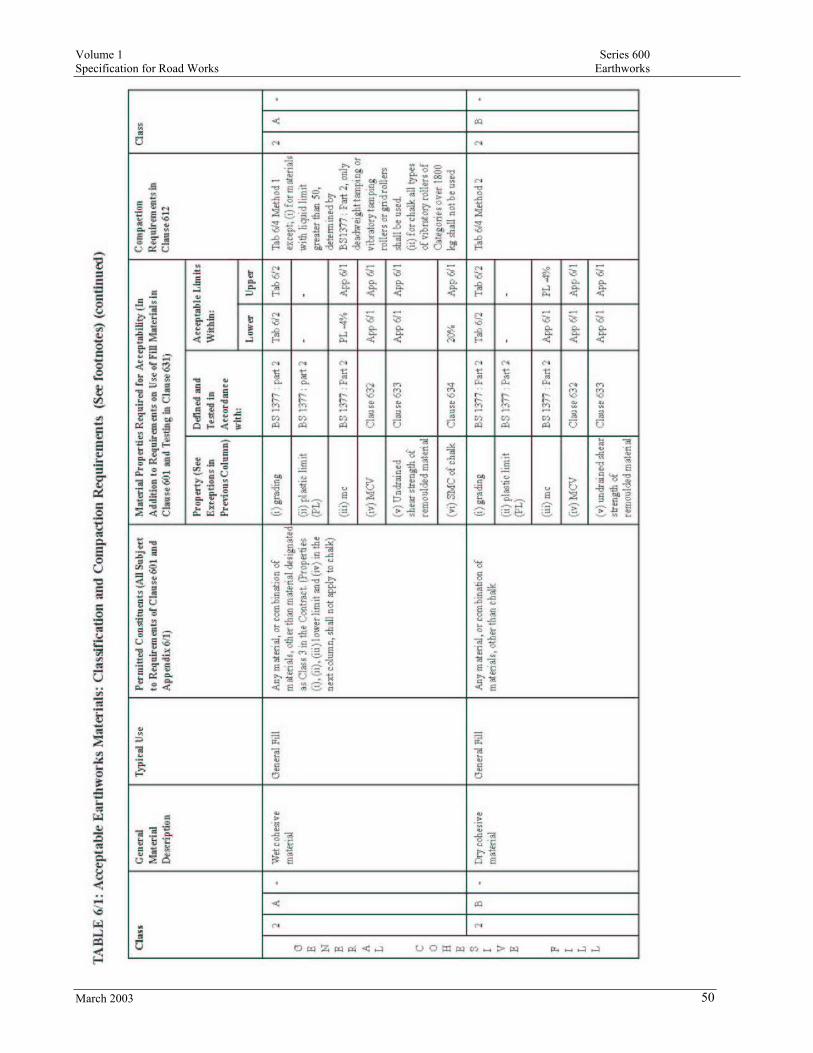
Volume 1 Series 600 Specification for Road Works Earthworks
March 2003 50

Volume 1 Series 600 Specification for Road Works Earthworks
March 2003 51
Rec
laim
ed
pulv
eriz
ed fu
el a
sh
cohe
sive
mat
eria
l N
ot a
vaila
ble
in
Mal
ta

Volume 1 Series 600 Specification for Road Works Earthworks
March 2003 52
5
C
-
Im
port
ed tu
rf
Tur
fing
M
ater
ial C
ompl
ying
wit
h B
S 3
969
-
-
-
-
-
5
C
-
Not
ava
ilabl
e in
Mal
ta
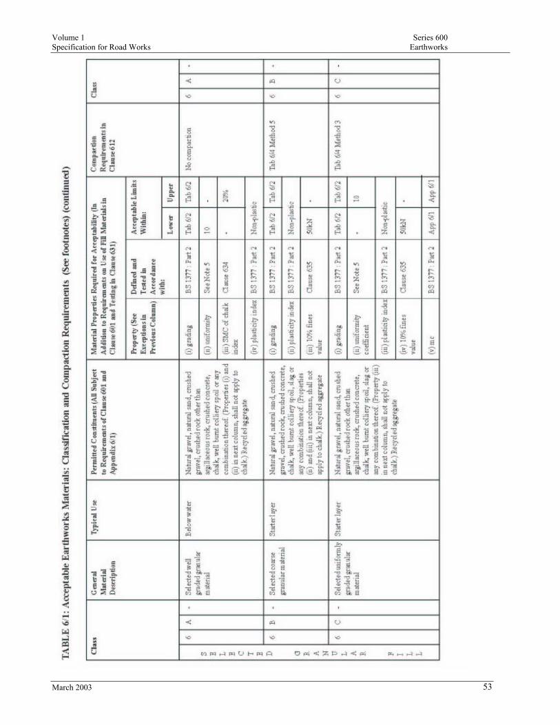
Volume 1 Series 600 Specification for Road Works Earthworks
March 2003 53
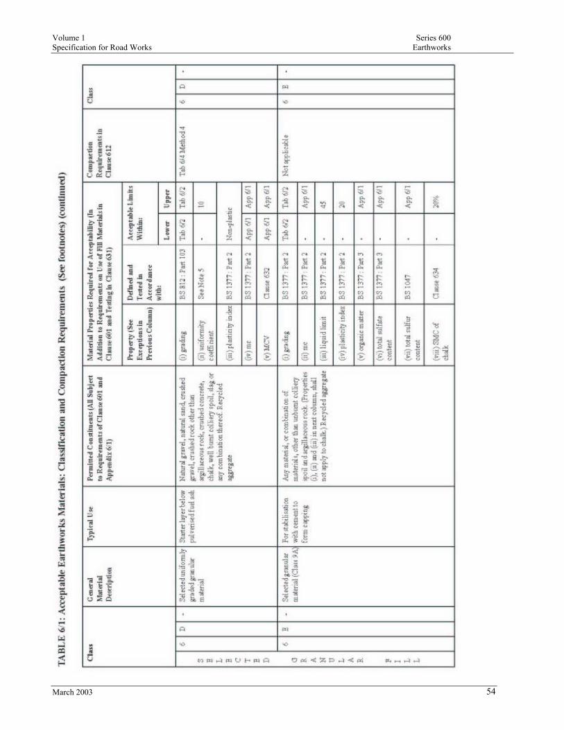
Volume 1 Series 600 Specification for Road Works Earthworks
March 2003 54
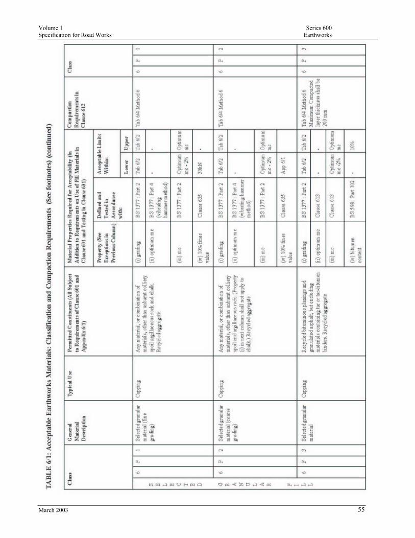
Volume 1 Series 600 Specification for Road Works Earthworks
March 2003 55

Volume 1 Series 600 Specification for Road Works Earthworks
March 2003 56

Volume 1 Series 600 Specification for Road Works Earthworks
March 2003 57
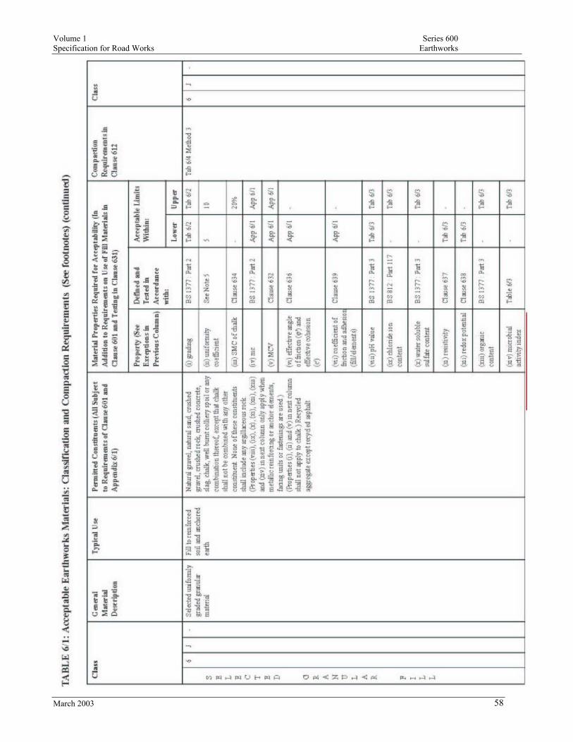
Volume 1 Series 600 Specification for Road Works Earthworks
March 2003 58

Volume 1 Series 600 Specification for Road Works Earthworks
March 2003 59

Volume 1 Series 600 Specification for Road Works Earthworks
March 2003 60
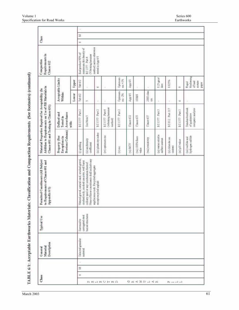
Volume 1 Series 600 Specification for Road Works Earthworks
March 2003 61
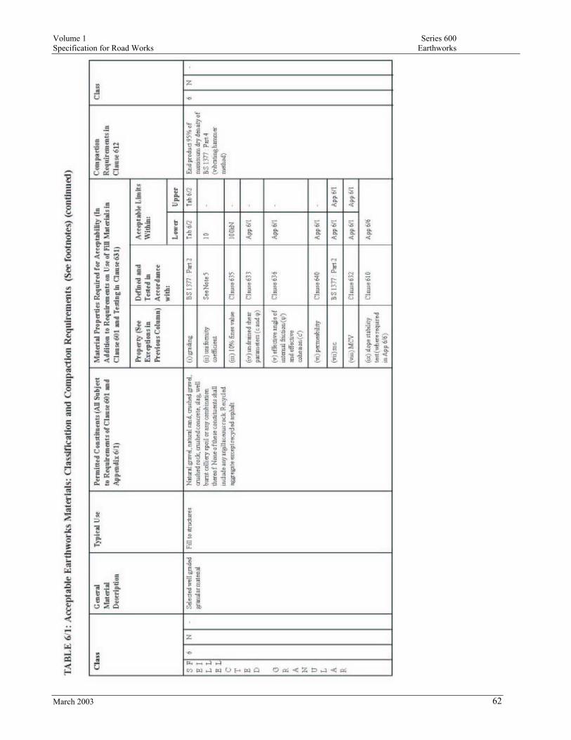
Volume 1 Series 600 Specification for Road Works Earthworks
March 2003 62

Volume 1 Series 600 Specification for Road Works Earthworks
March 2003 63

Volume 1 Series 600 Specification for Road Works Earthworks
March 2003 64

Volume 1 Series 600 Specification for Road Works Earthworks
March 2003 65

Volume 1 Series 600 Specification for Road Works Earthworks
March 2003 66
Not
ava
ilabl
e in
Mal
ta

Volume 1 Series 600 Specification for Road Works Earthworks
March 2003 67
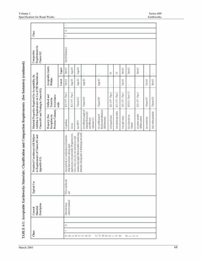
Volume 1 Series 600 Specification for Road Works Earthworks
March 2003 68
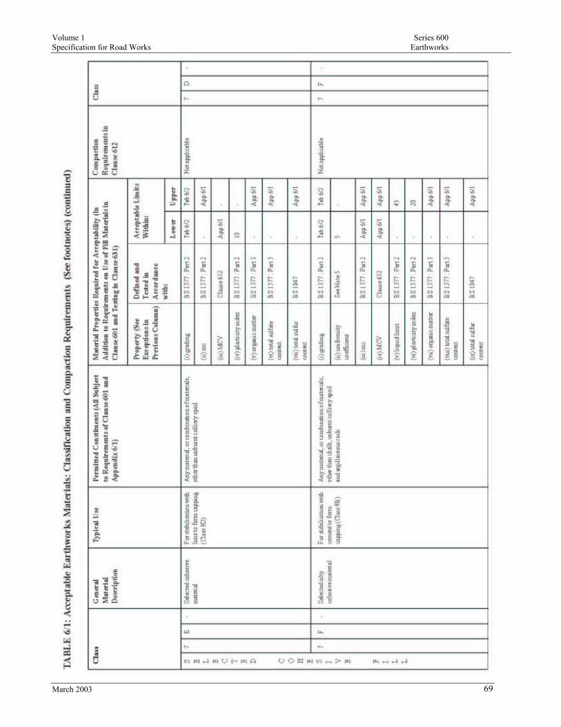
Volume 1 Series 600 Specification for Road Works Earthworks
March 2003 69

Volume 1 Series 600 Specification for Road Works Earthworks
March 2003 70
Sele
cted
co
nditi
oned
PFA
co
hesi
ve m
ater
ial
(Not
ava
ilabl
e in
M
atla
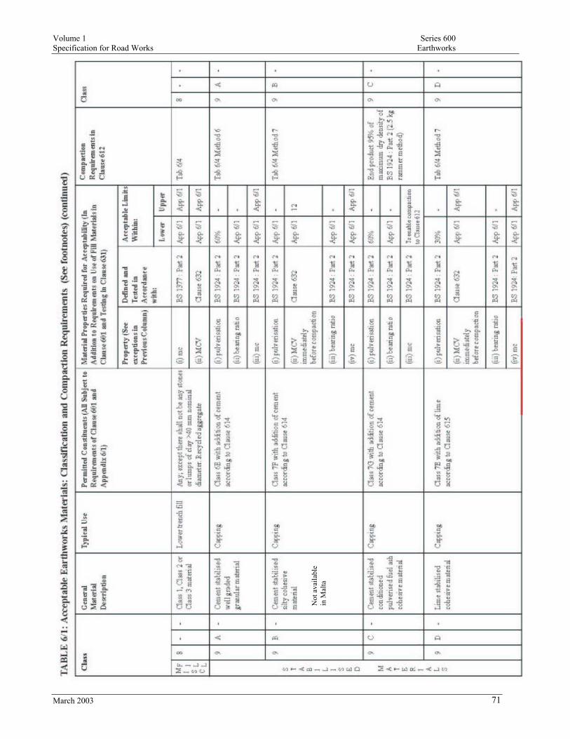
Volume 1 Series 600 Specification for Road Works Earthworks
March 2003 71
Not
ava
ilabl
e in
Mal
ta

Volume 1 Series 600 Specification for Road Works Earthworks
March 2003 72

Volume 1 Series 600 Specification for Road Works Earthworks
March 2003 73

Volume 1 Series 600 Specification for Road Works Earthworks
March 2003 74
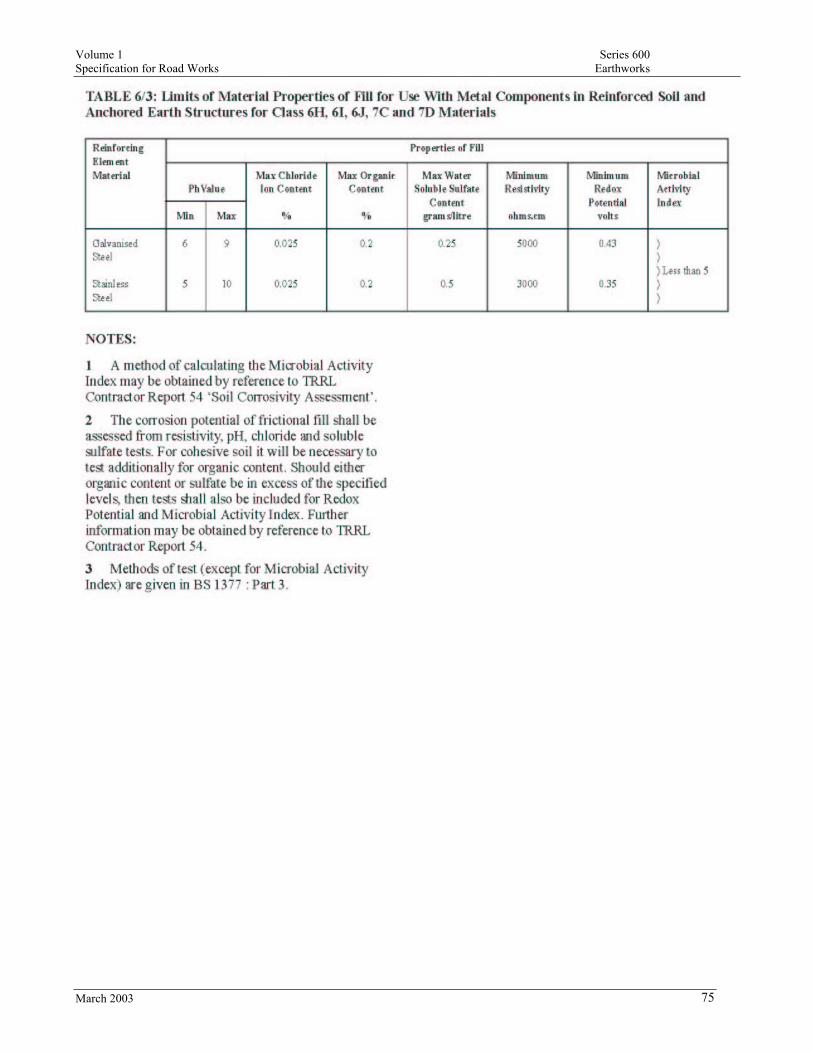
Volume 1 Series 600 Specification for Road Works Earthworks
March 2003 75
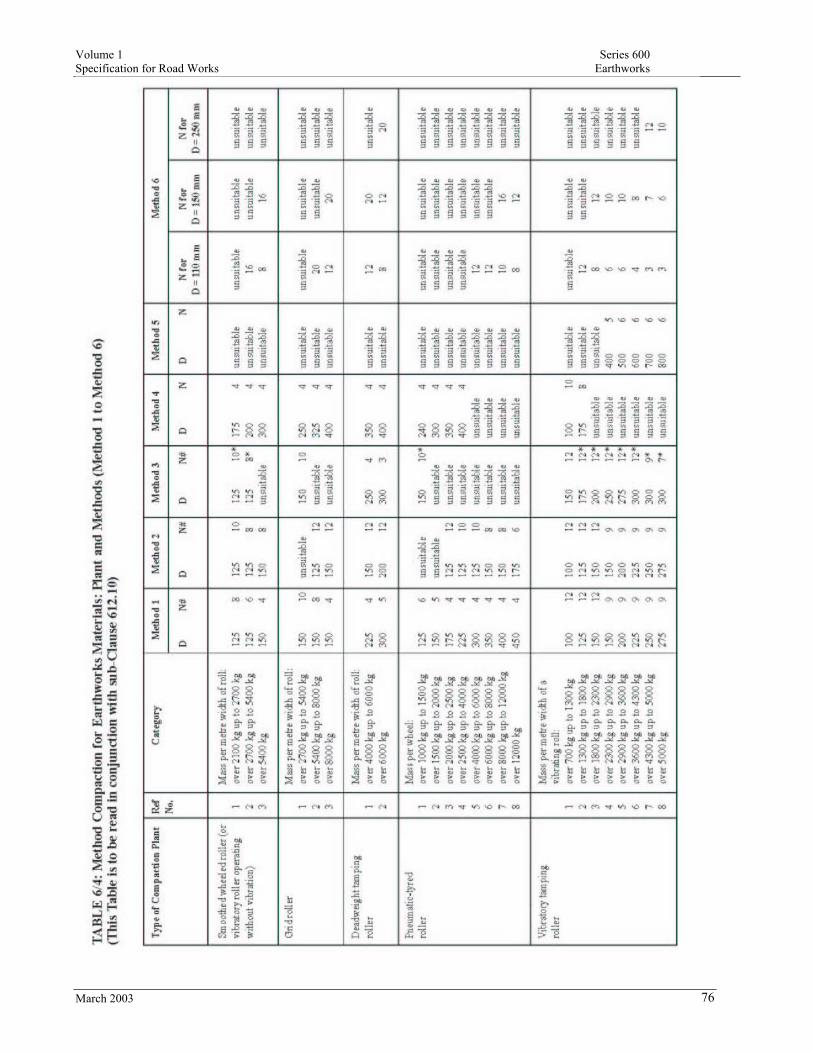
Volume 1 Series 600 Specification for Road Works Earthworks
March 2003 76

Volume 1 Series 600 Specification for Road Works Earthworks
March 2003 77
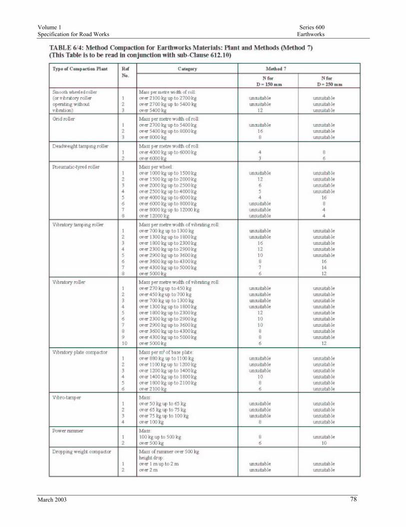
Volume 1 Series 600 Specification for Road Works Earthworks
March 2003 78

Volume 1 Series 600 Specification for Road Works Earthworks
March 2003 79