Embed Size (px)
Citation preview
© 2014 Power Sonix, Inc. All rights reserved.
Power Sonix, Inc.122 S. Church St., Martinsburg, WV 25401 USA
Tel: 304-267-7560; Fax 304-267-8691www.powersonix.com
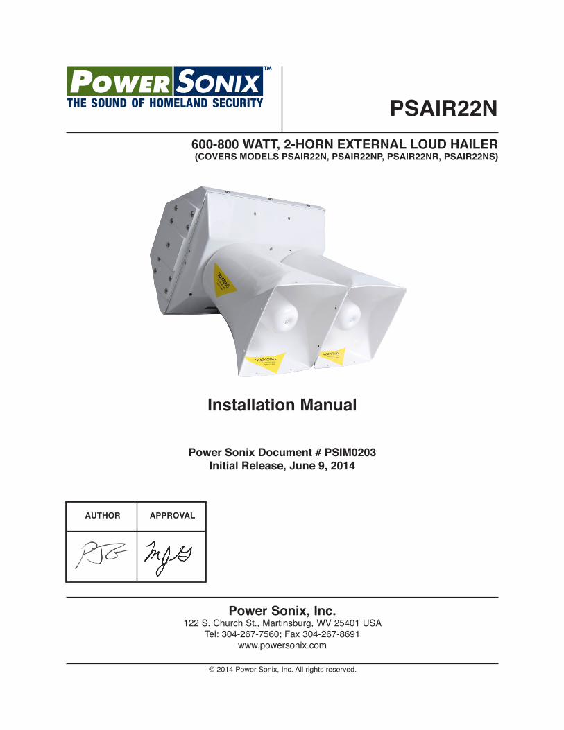
Power Sonix Document # PSIM0203Initial Release, June 9, 2014
600-800 WATT, 2-HORN EXTERNAL LOuD HAILER(COvERS MODELS PSAIR22N, PSAIR22NP, PSAIR22NR, PSAIR22NS)
PSAIR22N
Installation Manual
AuTHOR APPROvAL
REV. SECTIon- PAgE -
dESCRIPTIon dATE EdITEd- by -
PSAIR22n Installation Manual PSIM0203
REvISION HISTORY[ PSIM0203 ]
Initial Release 4/25/14 n/A
i
POWER SONIX, INC.www.powersonix.com
WARNING & DISCLAIMERS:
Changes or modifications not expressly approved by Power Sonix, Inc. could void the warranty and the user’s authority to operate the equipment.
This manual is designed to provide information about the PSAIR22N series of loud speakers. Every effort has been made to make this manual as complete and accurate as possible.
CAuTIONS:
This unit contains static sensitive devices. If granted authorization from Power Sonix to open any component, wear a grounded wrist strap and/or conductive gloves when handling printed circuit boards.
WARRANTY INFORMATION: The Model PSAIR22N is under warranty for two years from date of purchase. Failed units caused bydefective parts, or workmanship should be returned to:
Power Sonix, Inc.122 S. Church StreetMartinsburg, WV 25401 USATel: 304-267-7560Fax 304-267-8691
ii
PSAIR22n Installation Manual PSIM0203

POWER SONIX, INC.www.powersonix.com
PSAIR22n Installation Manual PSIM0203
WARRANTY
Power Sonix offers a Two-Year Limited Warranty on the PSAIR22N series loud hailers against defects in materials or workmanship. This warranty does not include damage caused by negligence, misuse of the equipment, gunfire or munitions, exposure to excessive heat or fire, accidents, or acts of God. The warranty is void if there is unauthorized access to the amplifier assembly or electronic components. The warranty is void if non-Power Sonix amplifiers or speaker drivers have been used in/with the system. Any repair or service required under this warranty will be authorized via an Return Merchandise Authorization (RMA) if an initial tech support call cannot remedy the situation in the field. Expressly excluded from this warranty are charges relating to removal of equipment from an aircraft or charges relating to reinstallation. Power Sonix will repair or replace (at Power Sonix’s option) any defective part found to be faulty during the Warranty Period. Faulty equipment must be returned to Power Sonix (or it’s authorized Warranty Depot) with transportation charges prepaid. Repaired (or replacement) equipment will be returned to the customer with freight charges collect. If the failure of a part occurs within the first 30 days of service, Power Sonix will return the repaired or replacement equipment prepaid. Power Sonix reserves the right to make changes in design, or additions to, or improvements in it’s products without obligation to install such additions and improvements in equipment previously manufactured. This Warranty is expressly in lieu of all other warranties expressed or implied, including any implied warranty of merchantability or fitness, and of all other obligations or liabilities on the part of the seller.
The Warranty Registration Card on the next page must be filled out and submitted to Power Sonix to effect your warranty. The installation service provider should record the date and place of installation on the warranty card. The warranty period begins on the date of the invoice from Power Sonix or it’s authorized distributor, representative, dealer or agent. The warranty card must be received by Power Sonix within 60 days of receipt of equipment.
Return Merchandise Authorization:To send equipment back for warranty or out-of-warranty service, please call Power Sonix to obtain a Return Merchandise Authorization (RMA). The RMA number provided MUST BE clearly marked on the shipping label. We will not accept equipment returns that do not have an RMA. Ship equipment to:
Power Sonix, Inc.RMA#__________122 South Church St.Martinsburg, WV 25401 USA
Telephone number (for Shipper’s Reference) is (304) 267-7560
iii
PSAIR22n Installation Manual PSIM0203
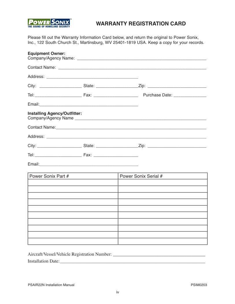
Please fill out the Warranty Information Card below, and return the original to Power Sonix, Inc., 122 South Church St., Martinsburg, WV 25401-1819 USA. Keep a copy for your records.
Equipment Owner:Company/Agency Name: _______________________________________________________
Contact name: _______________________________________________________________
Address: _______________________________________
City: __________________ State: __________________Zip: _________________________
Tel: ____________________ Fax: ___________________ Purchase date: ______________
Email: __________________________________________
Installing Agency/Outfitter:Company/Agency Name ________________________________________________________
Contact name: ________________________________________________________________
Address: ____________________________________________________________________
City: ___________________ State: __________________Zip: _________________________
Tel: ____________________ Fax: ___________________
Email: __________________________________________
Power Sonix Part # Power Sonix Serial #
Aircraft/Vessel/Vehicle Registration Number: ________________________________________Installation Date: _______________________________________________________________
iv
WARRANTY REGISTRATION CARD
POWER SONIX, INC.www.powersonix.com
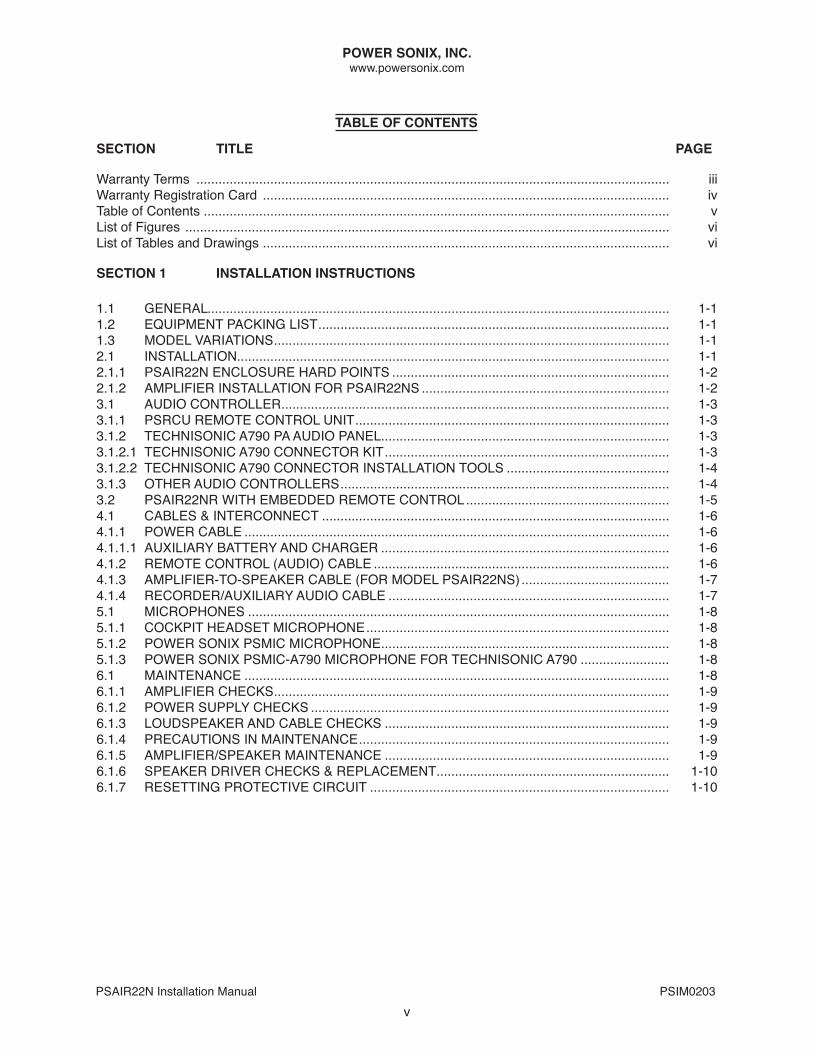
TABLE OF CONTENTS
PSAIR22n Installation Manual PSIM0203
SECTION TITLE PAGE
Warranty Terms ................................................................................................................................ iiiWarranty Registration Card .............................................................................................................. ivTable of Contents .............................................................................................................................. vList of Figures ................................................................................................................................... viList of Tables and drawings .............................................................................................................. vi
SECTION 1 INSTALLATION INSTRuCTIONS
1.1 gEnERAL............................................................................................................................. 1-11.2 EQUIPMEnT PACKIng LIST ............................................................................................... 1-11.3 ModEL VARIATIonS ........................................................................................................... 1-1 2.1 InSTALLATIon..................................................................................................................... 1-1 2.1.1 PSAIR22n EnCLoSURE HARd PoInTS ........................................................................... 1-22.1.2 AMPLIFIER InSTALLATIon FoR PSAIR22nS ................................................................... 1-23.1 AUdIo ConTRoLLER ......................................................................................................... 1-33.1.1 PSRCU REMoTE ConTRoL UnIT ..................................................................................... 1-33.1.2 TECHnISonIC A790 PA AUdIo PAnEL .............................................................................. 1-3 3.1.2.1 TECHnISonIC A790 ConnECToR KIT ............................................................................. 1-33.1.2.2 TECHnISonIC A790 ConnECToR InSTALLATIon TooLS ............................................ 1-43.1.3 oTHER AUdIo ConTRoLLERS ......................................................................................... 1-43.2 PSAIR22nR WITH EMbEddEd REMoTE ConTRoL ....................................................... 1-54.1 CAbLES & InTERConnECT .............................................................................................. 1-64.1.1 PoWER CAbLE ................................................................................................................... 1-6 4.1.1.1 AUXILIARy bATTERy And CHARgER .............................................................................. 1-64.1.2 REMoTE ConTRoL (AUdIo) CAbLE ................................................................................ 1-64.1.3 AMPLIFIER-To-SPEAKER CAbLE (FoR ModEL PSAIR22nS) ........................................ 1-74.1.4 RECoRdER/AUXILIARy AUdIo CAbLE ............................................................................ 1-75.1 MICRoPHonES .................................................................................................................. 1-85.1.1 CoCKPIT HEAdSET MICRoPHonE .................................................................................. 1-85.1.2 PoWER SonIX PSMIC MICRoPHonE .............................................................................. 1-85.1.3 PoWER SonIX PSMIC-A790 MICRoPHonE FoR TECHnISonIC A790 ........................ 1-86.1 MAInTEnAnCE ................................................................................................................... 1-86.1.1 AMPLIFIER CHECKS ........................................................................................................... 1-96.1.2 PoWER SUPPLy CHECKS ................................................................................................. 1-96.1.3 LoUdSPEAKER And CAbLE CHECKS ............................................................................. 1-96.1.4 PRECAUTIonS In MAInTEnAnCE .................................................................................... 1-96.1.5 AMPLIFIER/SPEAKER MAInTEnAnCE ............................................................................. 1-96.1.6 SPEAKER dRIVER CHECKS & REPLACEMEnT ............................................................... 1-106.1.7 RESETTIng PRoTECTIVE CIRCUIT ................................................................................. 1-10
v
POWER SONIX, INC.www.powersonix.com
PSAIR22n Installation Manual PSIM0203
vi
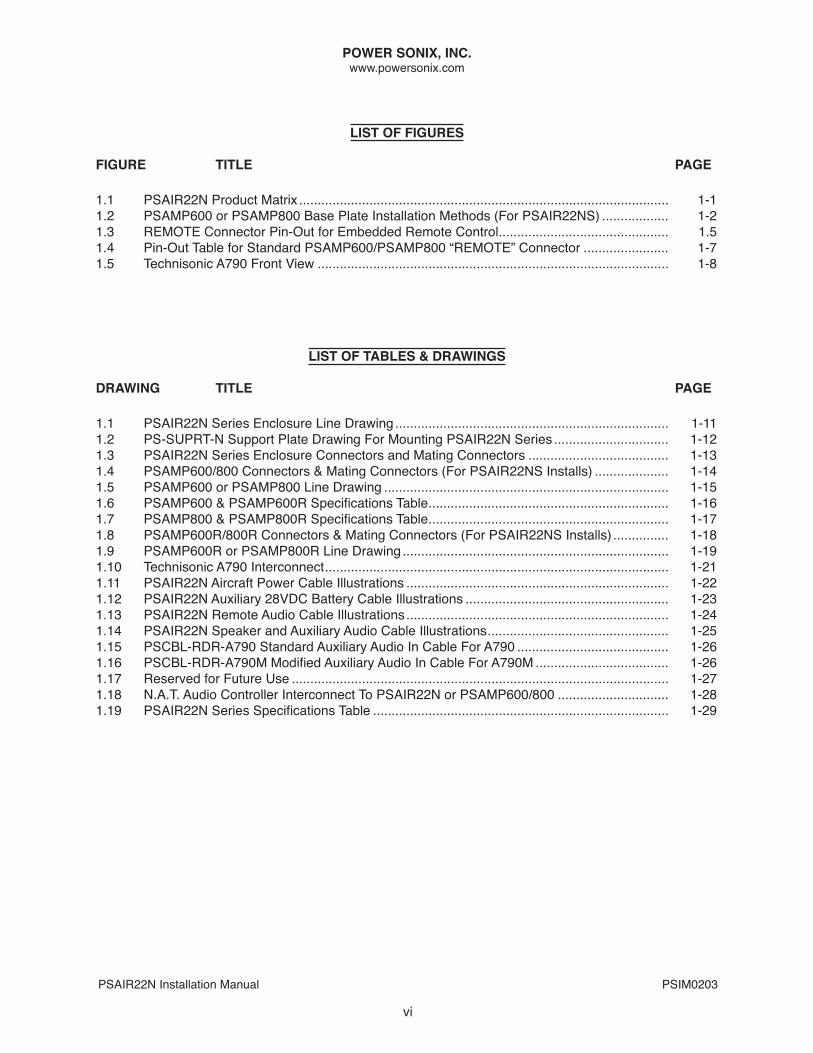
LIST OF FIGuRES
FIGuRE TITLE PAGE
1.1 PSAIR22n Product Matrix .................................................................................................... 1-11.2 PSAMP600 or PSAMP800 base Plate Installation Methods (For PSAIR22nS) .................. 1-21.3 REMoTE Connector Pin-out for Embedded Remote Control .............................................. 1.51.4 Pin-out Table for Standard PSAMP600/PSAMP800 “REMoTE” Connector ....................... 1-71.5 Technisonic A790 Front View ............................................................................................... 1-8
LIST OF TABLES & DRAWINGS
DRAWING TITLE PAGE
1.1 PSAIR22n Series Enclosure Line drawing .......................................................................... 1-111.2 PS-SUPRT-n Support Plate drawing For Mounting PSAIR22n Series ............................... 1-121.3 PSAIR22n Series Enclosure Connectors and Mating Connectors ...................................... 1-131.4 PSAMP600/800 Connectors & Mating Connectors (For PSAIR22nS Installs) .................... 1-141.5 PSAMP600 or PSAMP800 Line drawing ............................................................................. 1-151.6 PSAMP600 & PSAMP600R Specifications Table ................................................................. 1-161.7 PSAMP800 & PSAMP800R Specifications Table ................................................................. 1-171.8 PSAMP600R/800R Connectors & Mating Connectors (For PSAIR22nS Installs) ............... 1-181.9 PSAMP600R or PSAMP800R Line drawing ........................................................................ 1-191.10 Technisonic A790 Interconnect ............................................................................................. 1-211.11 PSAIR22n Aircraft Power Cable Illustrations ....................................................................... 1-221.12 PSAIR22N Auxiliary 28VDC Battery Cable Illustrations ....................................................... 1-231.13 PSAIR22n Remote Audio Cable Illustrations ....................................................................... 1-241.14 PSAIR22N Speaker and Auxiliary Audio Cable Illustrations ................................................. 1-251.15 PSCBL-RDR-A790 Standard Auxiliary Audio In Cable For A790 ......................................... 1-261.16 PSCBL-RDR-A790M Modified Auxiliary Audio In Cable For A790M .................................... 1-261.17 Reserved for Future Use ...................................................................................................... 1-27 1.18 n.A.T. Audio Controller Interconnect To PSAIR22n or PSAMP600/800 .............................. 1-281.19 PSAIR22N Series Specifications Table ................................................................................ 1-29
POWER SONIX, INC.www.powersonix.com
PSAIR22n Installation Manual PSIM0203
1-1
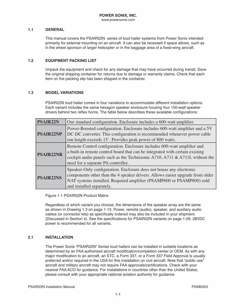
1.1 GENERAL
This manual covers the PSAIR22N series of loud hailer systems from Power Sonix intended primarily for external mounting on an aircraft. It can also be recessed if space allows, such as in the wheel sponson of larger helicopter or in the baggage area of a fixed-wing aircraft.
1.2 EQuIPMENT PACKING LIST
Unpack the equipment and check for any damage that may have occurred during transit. Save the original shipping container for returns due to damage or warranty claims. Check that each item on the packing slip has been shipped in the container.
1.3 MODEL vARIATIONS
PSAIR22n loud hailer comes in four variations to accommodate different installation options. Each variant includes the same hexagon speaker enclosure housing four 150-watt speaker drivers behind two reflex horns. The table below describes these available configurations:
Figure 1.1 PSAIR22n Product Matrix
Regardless of which variant you choose, the dimensions of the speaker array are the same as shown in Drawing 1.3 on page 1-13. Power, remote (audio), speaker, and auxiliary audio cables (or connector kits) as specifically ordered may also be included in your shipment. (Discussed in Section 4). See the specifications for PSAIR22N variants on page 1-29. 28VDC power is recommended for all variants.
2.1 INSTALLATION
The Power Sonix “PSAIR22n” Series loud hailers can be installed in suitable locations as determined by an FAA authorized aircraft modification/completion center or OEM. As with any major modification to an aircraft, an STC, a Form 337, or a Form 337 Field Approval is usually preferred and/or required in the USA for this installation on civil aircraft. Note that “public use” aircraft and military aircraft may not require FAA approvals/certifications. Check with your nearest FAA ACo for guidance. For installations in countries other than the United States, please consult with your appropriate national aviation authority for guidance.
PSAIR22N Our standard configuration. Enclosure includes a 600-watt amplifier.
PSAIR22NPPower-Boosted configuration. Enclosure includes 600-watt amplifier and a 5V DC-DC converter. This configuration is recommended whenever power cable run length exceeds 15’. Provides peak power of 800 watts.
PSAIR22NR
Remote Control configuration. Enclosure includes 600-watt amplifier and a built-in remote control board that can be integrated with certain existing cockpit audio panels such as the Technisonic A710, A711 & A711L without the need for a separate PA controller.
PSAIR22NS
Speaker-Only configuration. Enclosure does not house any electronic components other than the 4 speaker drivers. Allows easier upgrade from older NAT systems installed. Required amplifier (PSAMP600 or PSAMP800) sold and installed separately.
POWER SONIX, INC.www.powersonix.com
PSAIR22n Installation Manual PSIM0203
1-2
2.1.1 PSAIR22N ENCLOSuRE HARD POINTS
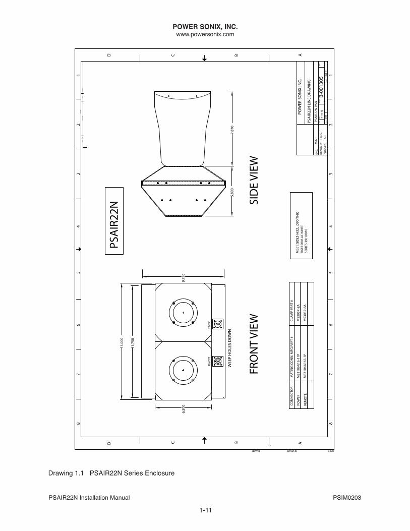
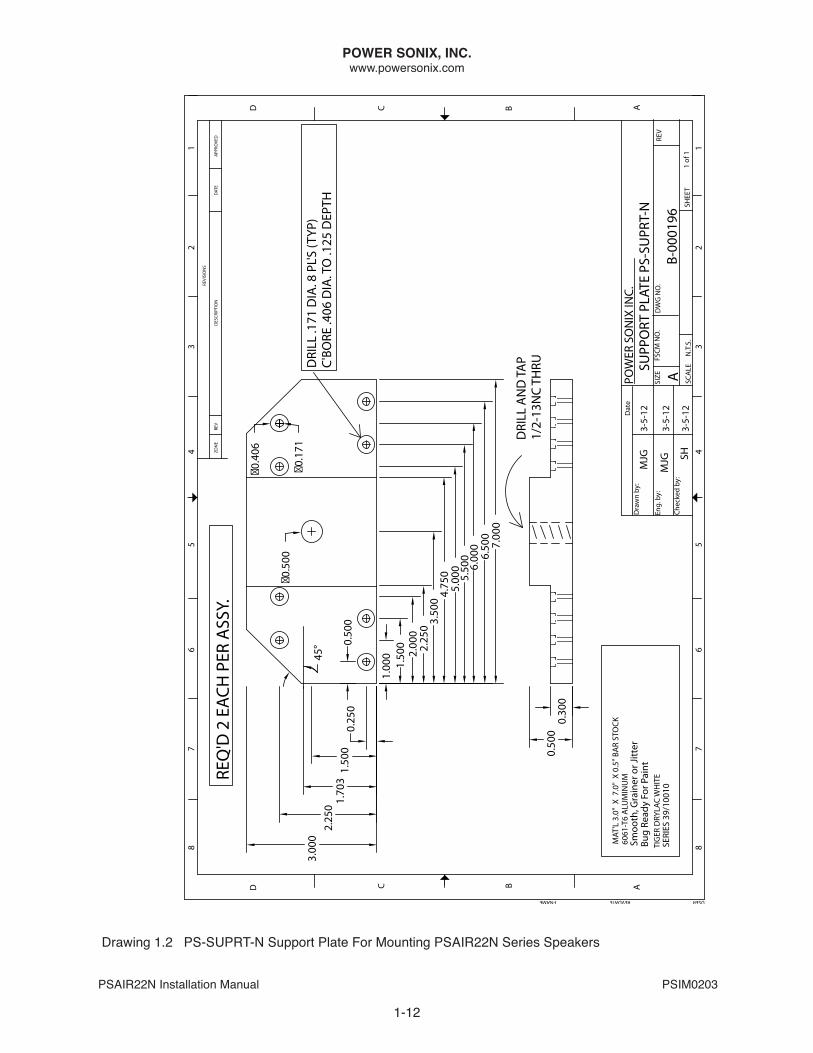
There are many possible locations and methods to attach the PSAIR22N speaker enclosure to any given aircraft. These include attachment to existing approved mounts attached to structural hard points, mounting to cross tube/support struts, Meeker mounts, etc. drawing 1.1 showing the dimensions of the PSAIR22n enclosure is provided on page 1-11.
To facilitate mounting of the PSAIR22N speaker array, each side of the PSAIR22N enclosure has 8 pre-drilled holes with 8-32 PEM nuts for attachment of bracket support plates. These plates are sold in pairs (PS-SUPRT-n) or as part of the PSAIR22n demo bracket Kit (PSbRKT22n). When attaching the plates with the eight screws provided, hand start the screws to avoid stripping the PEM nuts out of metal inadvertently.
drawing 1.2 for the PS-SUPRT-n Support Plates is provided on page 1-12. Please refer to this drawing when designing and fabricating any custom bracket or mounting apparatus for your aircraft so that the installation will securely attach to the enclosure and/or support plates and target the speaker array in the desired downward position and angle of sound projection.
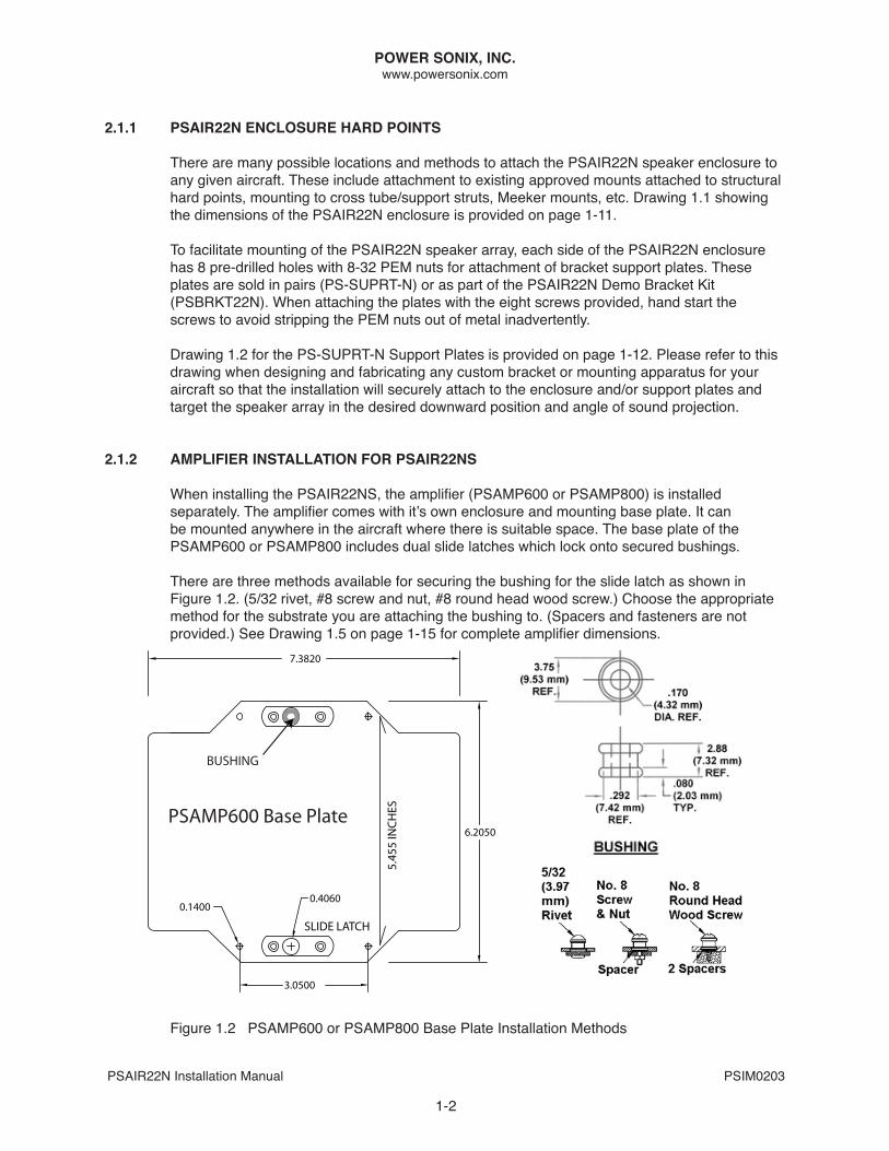
2.1.2 AMPLIFIER INSTALLATION FOR PSAIR22NS
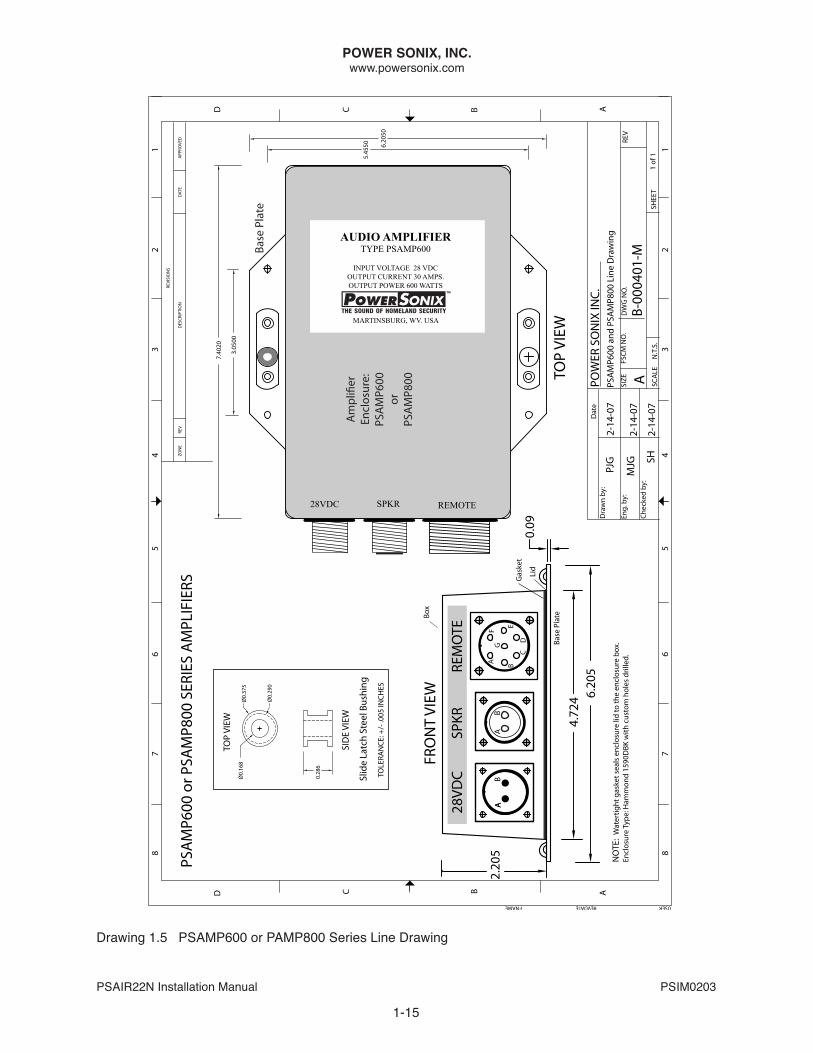
When installing the PSAIR22NS, the amplifier (PSAMP600 or PSAMP800) is installed separately. The amplifier comes with it’s own enclosure and mounting base plate. It can be mounted anywhere in the aircraft where there is suitable space. The base plate of the PSAMP600 or PSAMP800 includes dual slide latches which lock onto secured bushings.
There are three methods available for securing the bushing for the slide latch as shown in Figure 1.2. (5/32 rivet, #8 screw and nut, #8 round head wood screw.) Choose the appropriate method for the substrate you are attaching the bushing to. (Spacers and fasteners are not provided.) See Drawing 1.5 on page 1-15 for complete amplifier dimensions.
0.1400
7.3820
5.45
5 IN
CHES
6.2050
0.4060
SLIDE LATCH
3.0500
PSAMP600 Base Plate
BUSHING
Figure 1.2 PSAMP600 or PSAMP800 base Plate Installation Methods

POWER SONIX, INC.www.powersonix.com
PSAIR22n Installation Manual PSIM0203
1-3
3.1 AuDIO CONTROLLER
The PSAIR22n (or the separate PSAMP600 or PSAMP800 if connected to the PSAIR22nS) can connect to most tactical airborne audio panels and public address (PA) controllers equipped with a suitable “PA” or audio out capability such as the Power Sonix PSRCU, the Technisonic A710, A711, A711L and A790 audio panels, and many Cobham/NAT/AEM PA controllers. Please note that “intercom” or “paging” connections designed for speaking into the cabin or interior of the aircraft are typically not suited for our high-powered speakers. Please consult the Installation manual for your audio/PA controllers for appropriate installation instructions specific to your equipment. If necessary, consult with your Power Sonix agent/dealer or the Power Sonix factory prior to installation for guidance.
3.1.1 PSRCu REMOTE CONTROL uNIT
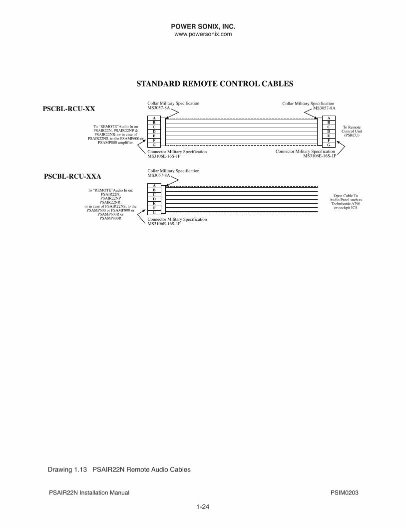
If using a Power Sonix PSRCU remote control unit, installation and operating instructions for the PSRCU can be found in Power Sonix document PSIM0011. An audio signal connection is made between the “Remote” connector on the PSAIR22n (or on the separate PSAMP600 or PSAMP800 in the case of the PSAIR22nS) and the PSRCU with a “Remote” cable. See Drawing 1.13 for the applicable Remote cable for your configuration. Please note that “XX” denotes cable length in our cable descriptions/part# (10’ standard, other lengths by order).
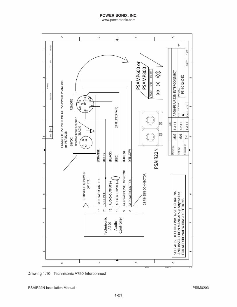
3.1.2 TECHNISONIC A790 PA AuDIO PANEL
Complete installation instructions for the Technisonic A790 PA controller and other Technisonic audio panels can be found at http://til.ca. The Interconnect drawing for connecting the Technisonic A790 to the “Remote” connector on the PSAIR22n (or on the separate PSAMP600 or PSAMP800 in the case of the PSAIR22nS) is drawing 1.10 on page 1-21.
3.1.2.1 TECHNISONIC A790 CONNECTOR KIT
When ordering the A790 audio panel, the associated installation connector kit PS-Conn-A790is required. This kit consists of the 25-pin DB connector and 25 pins. The interconnect diagram provided in this manual only illustrates how the 6 wires from the PSAMP600 “REMOTE” connector attach to the A790’s 25-pin DB connector. The determination of how to connect the remaining pins on the A790 connector will need to be made by the installer in consultation with the appropriate manuals for the other audio and radio components in the communications system configuration. The A790 draws 700 mA current.
If you desire to purchase the parts for the connector kit directly from a distributor of electronic components, we offer the following resource:
Positronic Industries423 n CampbellSpringfield, MO 65806 USAPhone: 1-800-641-4054Web Site: www.connectpositronic.com
25-PIn d Connector Part #Sd25F00JVL0
Connector Pins for 25-PIN Part #FC7520D (Quantity 25 needed per connector)
POWER SONIX, INC.www.powersonix.com
PSAIR22n Installation Manual PSIM0203
NOTE: Power Sonix is not the authority for the connectivity of third party avionics equipment to the Technisonic A790. Please consult with Technisonic Industries Ltd and the manufacturer of your other avionics components for assistance in connecting their components to the A790.
3.1.2.2 TECHNISONIC A790 CONNECTOR INSTALLATION TOOLS
To assemble the 25-pin DB connector accurately, you will need tools specific to this type of DB connector. These include an “Insertion/Extraction Tool”, a “Positioner Tool” and a “Hand Crimp Tool”. If you are in need of these tools in advance of your planned installation, we offer the following resource:
Positronic Industries423 n CampbellSpringfield, MO 65806 USAPhone: 1-800-641-4054Web Site: www.connectpositronic.com
Insertion/Extraction Tool Part #4711-2-0-0 Positioner Tool Part #9502-10-0-0Hand Crimp Tool Part #9507-0-0-0
(Note: It can take up to 8 weeks for delivery of these items.)
3.1.3 OTHER AuDIO CONTROLLERS
For installation instructions for other Technisonic, Cobham, NAT, Anodyme (AEM), etc. audio panels and/or PA controllers, please consult the manufacturer’s manual.
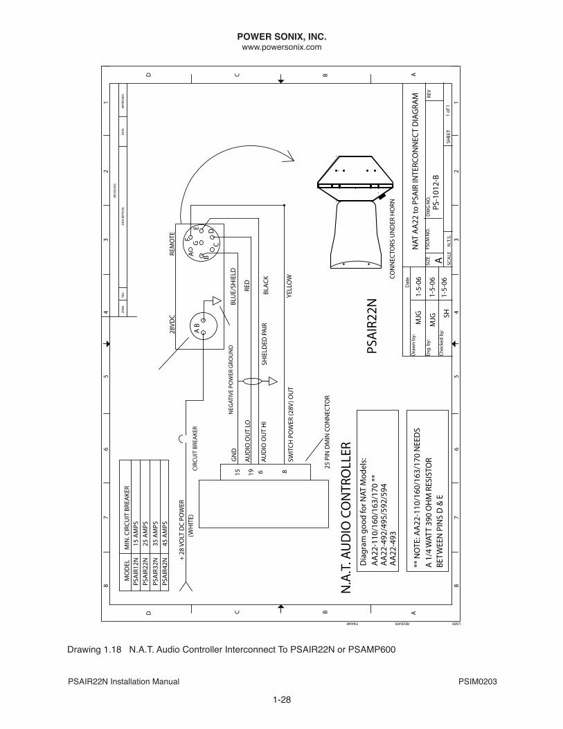
The Northern Airborne (NAT) or Anodyne Electrical Manufacturing (AEM) AA21 and AA22 series audio controllers can be used with the PSAIR22n. The AA22 series wiring diagram is shown in drawing 1.18 on page 1-28.
noTE: if using the NAT AA21-400 audio controller, it will be necessary to add a 390 ohm, ½ watt resistor across Pins d & E of the Power Sonix “Remote” input to prevent over-driving and distortion. This can be done at the factory internal to the amplifier or installed externally.
For assistance with the Interconnect for the PSAIR22n and such other audio controllers, consult with your authorized Power Sonix representative or the Power Sonix factory.
1-4
POWER SONIX, INC.www.powersonix.com
PSAIR22n Installation Manual PSIM0203
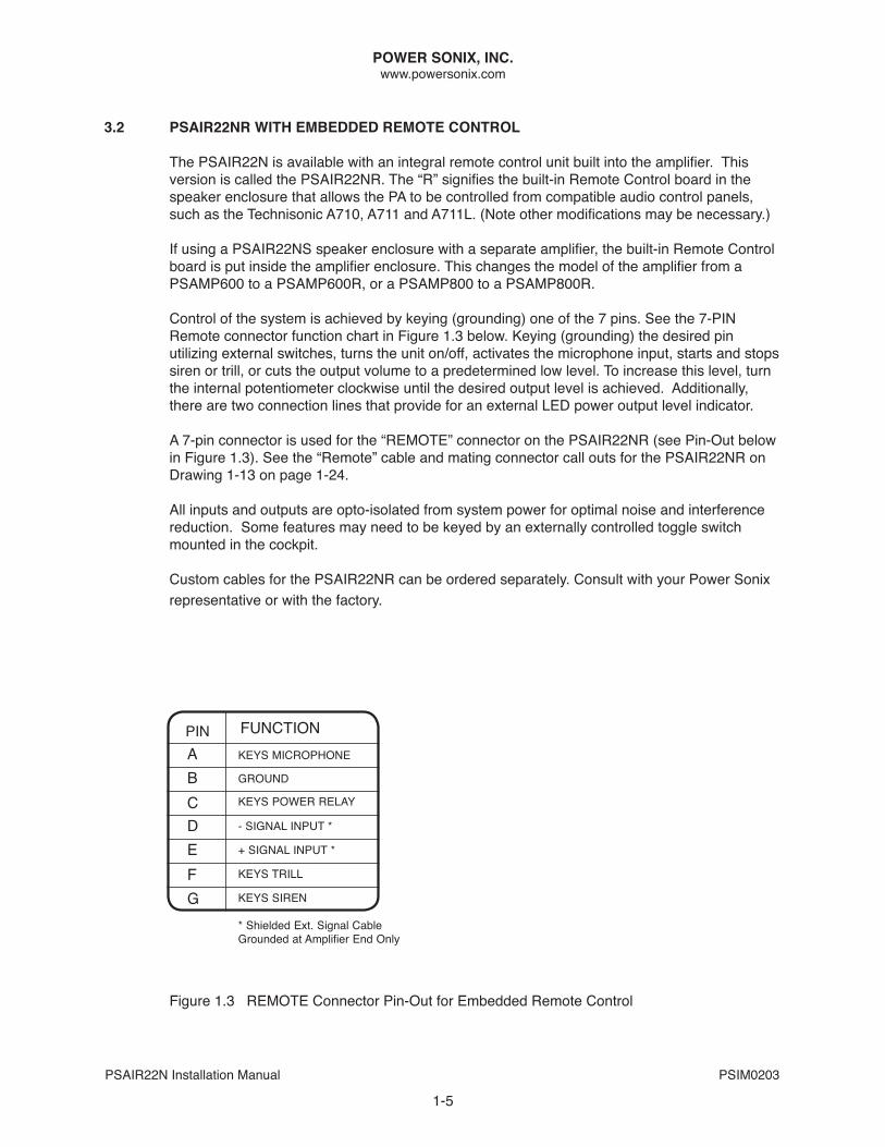
3.2 PSAIR22NR WITH EMBEDDED REMOTE CONTROL
The PSAIR22n is available with an integral remote control unit built into the amplifier. This version is called the PSAIR22nR. The “R” signifies the built-in Remote Control board in the speaker enclosure that allows the PA to be controlled from compatible audio control panels, such as the Technisonic A710, A711 and A711L. (Note other modifications may be necessary.)
If using a PSAIR22nS speaker enclosure with a separate amplifier, the built-in Remote Control board is put inside the amplifier enclosure. This changes the model of the amplifier from a PSAMP600 to a PSAMP600R, or a PSAMP800 to a PSAMP800R.
Control of the system is achieved by keying (grounding) one of the 7 pins. See the 7-PIN Remote connector function chart in Figure 1.3 below. Keying (grounding) the desired pin utilizing external switches, turns the unit on/off, activates the microphone input, starts and stops siren or trill, or cuts the output volume to a predetermined low level. To increase this level, turn the internal potentiometer clockwise until the desired output level is achieved. Additionally, there are two connection lines that provide for an external LEd power output level indicator. A 7-pin connector is used for the “REMoTE” connector on the PSAIR22nR (see Pin-out below in Figure 1.3). See the “Remote” cable and mating connector call outs for the PSAIR22nR on drawing 1-13 on page 1-24.
All inputs and outputs are opto-isolated from system power for optimal noise and interference reduction. Some features may need to be keyed by an externally controlled toggle switch mounted in the cockpit.
Custom cables for the PSAIR22NR can be ordered separately. Consult with your Power Sonix representative or with the factory.
FUnCTIonAbCdEFg
KEyS PoWER RELAy
gRoUnd
KEyS MICRoPHonE
- SIgnAL InPUT *
+ SIgnAL InPUT *
KEyS TRILL
KEyS SIREn
* Shielded Ext. Signal Cable Grounded at Amplifier End Only
PIn
1-5
Figure 1.3 REMoTE Connector Pin-out for Embedded Remote Control
POWER SONIX, INC.www.powersonix.com
PSAIR22n Installation Manual PSIM0203
1-6
4.1 CABLES & INTERCONNECT
In general, every Power Sonix external mount installation will require: 1) a cable to deliver power to the speaker enclosure or separate amplifier, 2) a cable to deliver the audio signal from the audio controller/remote control to the amplified speaker enclosure or separate amplifier.In the case of the PSAIR22NS where the amplifier is installed separately, a third cable is needed: 3) a speaker cable to connect the amplifier to the PSAIR22NS enclosure.
If a PSRCU Remote Control Unit is used as the audio controller, an additional cable to connect the PSRCU to a commercial MP3 player/iPod type device is needed (PSCBL-RDR-1A).
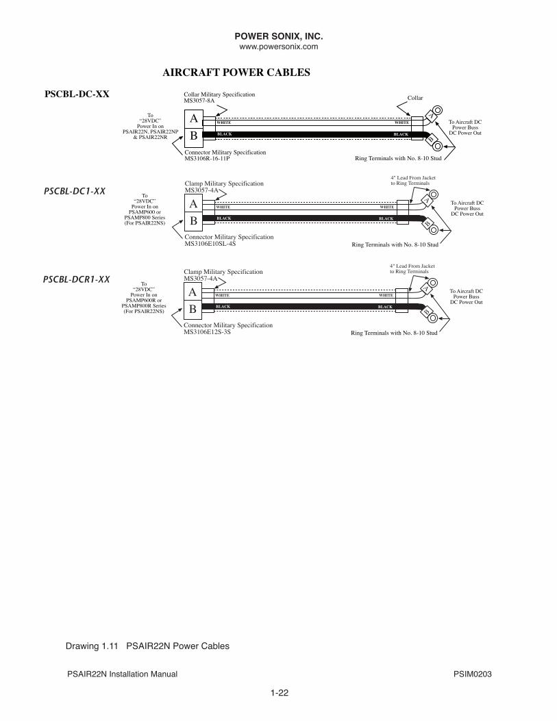
4.1.1 POWER CABLE
The PSAIR22N can be powered from the aircraft power buss, or alternatively from an auxiliary 28VDC battery pack supplied by Power Sonix. Power Sonix can make the cable for you or connector kits are available for you to make your own cables. See Drawing 1-11 for standard power cables to connect to aircraft power, Drawing 1-12 for cables to auxiliary 28VDC batteries.
NOTE: In our cable product names, “XX” denotes the length of the cable in feet and is to be specified for each installation by the installer at the time of ordering the cables from Power Sonix. If not specified, 10’ is our standard length for power and remote (audio) cables.
Standard aircraft power buss cables will have a 2-pin female connector to connect to the 28dVC male connector on the PSAIR22n enclosure (or in the case of the PSAIR22nS, to the PSAMP600/PSAMP800 series amplifier). The other end will have ring terminals to attach to the aircraft’s DC power supply. If using a Power Sonix auxiliary 28 VDC battery pack, the cable will have a 2-pin female connector appropriate for the specific Power Sonix battery being used.
Power Boosted Configuration: If the installation location on your aircraft results in power cable lengths in excess of 15’, we recommend 12 AWG or lower stranded cable. Alternatively, you can add a “power boost” to the PSAIR22N making it a PSAIR22NP. For PSAIR22nS installs, adding the “power boost” to the PSAMP600 turns it into a PSAMP800. This compensates for natural power losses over these longer power cable lengths. Please specify appropriate parts in bold when configuring your solution with this option and requesting quotes.
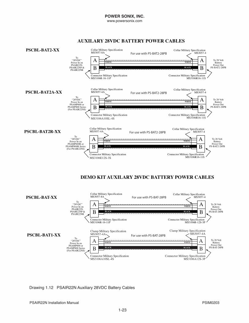
4.1.1.1 AuXILIARY BATTERY AND CHARGERPower Sonix offers an auxiliary 28VDC sealed lead-acid battery for airborne applications when tying into the aircraft power buss is not an option. This battery, PS-BAT2-28PB, will have one connector on the top, used for delivering power to the amplifier or amplified speaker array, and for connecting the AC Charger, PS-CHGR-28/5. The power cable for the battery is shown in Drawing 1-12. The Charger has a customized cable for quick attachment to the battery pack.
4.1.2 REMOTE CONTROL (AuDIO) CABLE
The PSAIR22N installation requires a cable from the audio controller (PSRCU, Technisonic A790, etc.) to the “REMoTE” connector on the PSAIR22n (or in the case of the PSAIR22nS, on the PSAMP600/PSAMP800 series amplifier). Illustrations of our Standard “Remote” cables, as well as Remote cables for the “Embedded Remote” variants (PSAIR22nR, PSAM600R and PSAMP600R) can be found on drawing 1.13.
POWER SONIX, INC.www.powersonix.com
PSAIR22n Installation Manual PSIM0203
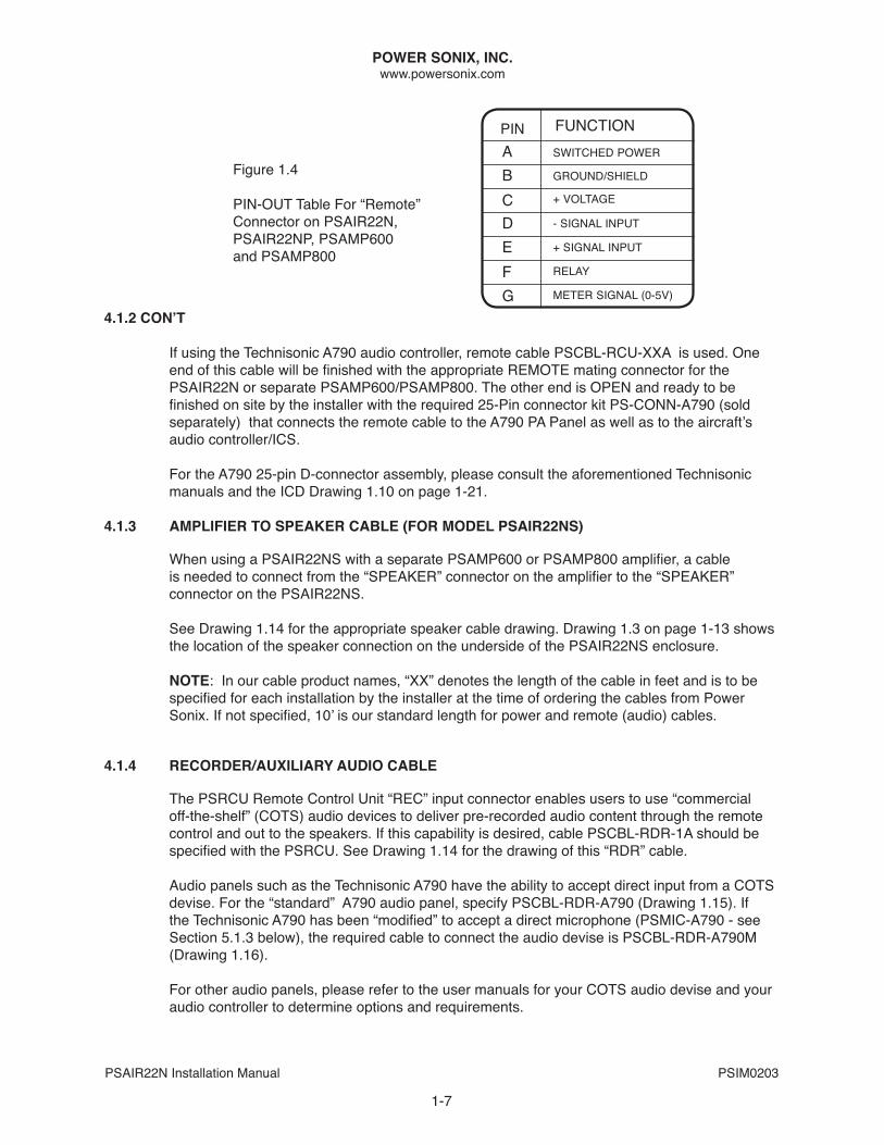
4.1.2 COn’t
If using the Technisonic A790 audio controller, remote cable PSCbL-RCU-XXA is used. one end of this cable will be finished with the appropriate REMOTE mating connector for the PSAIR22N or separate PSAMP600/PSAMP800. The other end is OPEN and ready to be finished on site by the installer with the required 25-Pin connector kit PS-CONN-A790 (sold separately) that connects the remote cable to the A790 PA Panel as well as to the aircraft’s audio controller/ICS.
For the A790 25-pin D-connector assembly, please consult the aforementioned Technisonic manuals and the ICd drawing 1.10 on page 1-21.
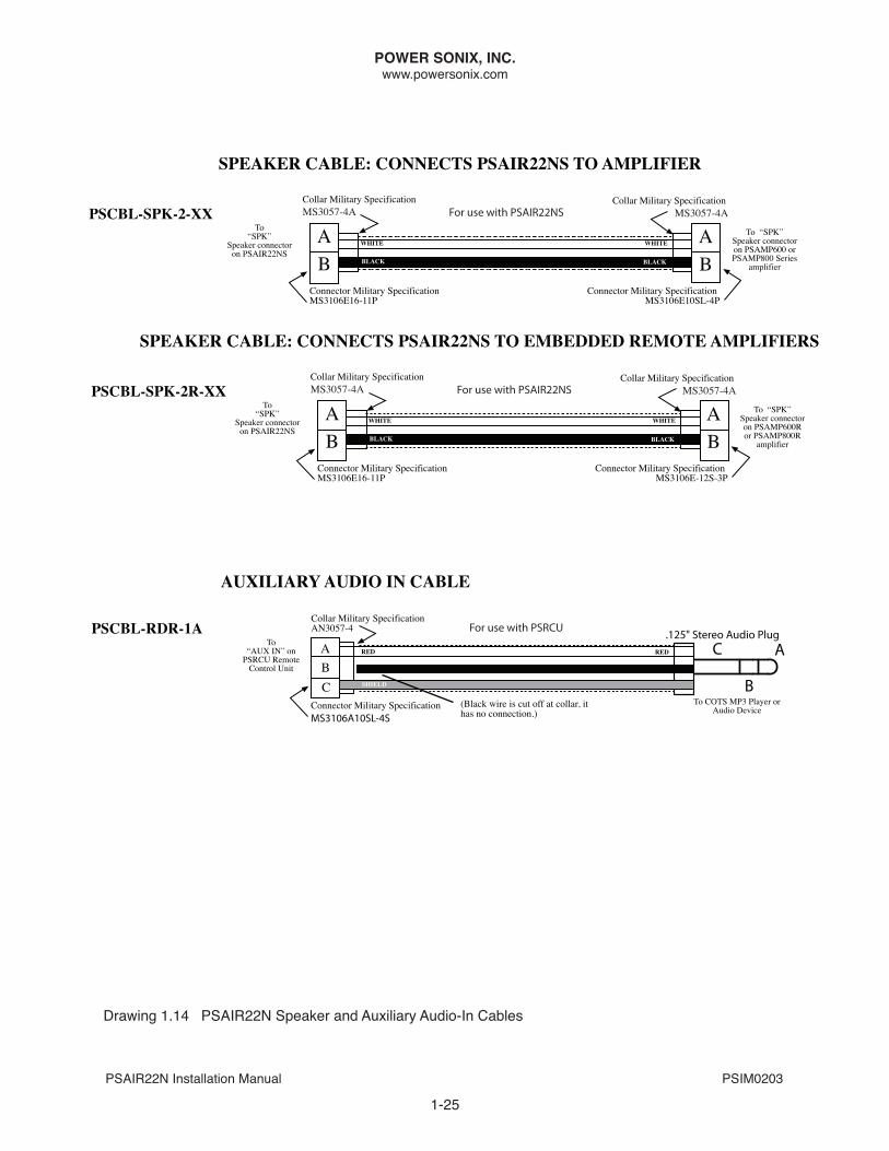
4.1.3 AMPLIFIER TO SPEAKER CABLE (FOR MODEL PSAIR22NS)
When using a PSAIR22NS with a separate PSAMP600 or PSAMP800 amplifier, a cable is needed to connect from the “SPEAKER” connector on the amplifier to the “SPEAKER” connector on the PSAIR22nS.
See drawing 1.14 for the appropriate speaker cable drawing. drawing 1.3 on page 1-13 shows the location of the speaker connection on the underside of the PSAIR22nS enclosure.
NOTE: In our cable product names, “XX” denotes the length of the cable in feet and is to be specified for each installation by the installer at the time of ordering the cables from Power Sonix. If not specified, 10’ is our standard length for power and remote (audio) cables.
4.1.4 RECORDER/AuXILIARY AuDIO CABLE
The PSRCU Remote Control Unit “REC” input connector enables users to use “commercial off-the-shelf” (CoTS) audio devices to deliver pre-recorded audio content through the remote control and out to the speakers. If this capability is desired, cable PSCBL-RDR-1A should be specified with the PSRCU. See Drawing 1.14 for the drawing of this “RDR” cable.
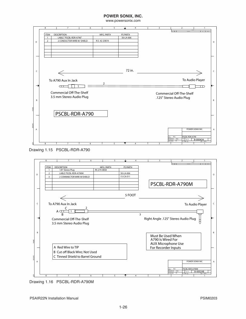
Audio panels such as the Technisonic A790 have the ability to accept direct input from a COTS devise. For the “standard” A790 audio panel, specify PSCBL-RDR-A790 (Drawing 1.15). If the Technisonic A790 has been “modified” to accept a direct microphone (PSMIC-A790 - see Section 5.1.3 below), the required cable to connect the audio devise is PSCBL-RDR-A790M (drawing 1.16).
For other audio panels, please refer to the user manuals for your COTS audio devise and your audio controller to determine options and requirements.
1-7
FUnCTIonAbCdEFg
+ VoLTAgE
gRoUnd/SHIELd
SWITCHEd PoWER
- SIgnAL InPUT
+ SIgnAL InPUT
RELAy
METER SIgnAL (0-5V)
PIn
Figure 1.4
PIn-oUT Table For “Remote” Connector on PSAIR22n, PSAIR22nP, PSAMP600 and PSAMP800
POWER SONIX, INC.www.powersonix.com
PSAIR22n Installation Manual PSIM0203
1-8
5.1 MICROPHONE
The microphone used in conjunction with the Power Sonix PA system can be the microphone in the cockpit headsets used by the crew for radio communications, or it can be a separate hand-held microphone provided by Power Sonix (PSMIC). Which method you use will depend upon preference of the flight crew and the audio controller chosen for your installation.
5.1.1 COCKPIT HEADSET MICROPHONES
The microphone used in most tactical cockpit headsets (such as david Clark) can be connected to the PA when a PA audio panel such as the Technisonic A790 PA panel is used. The controls on the A790 will direct the audio signal from the main audio panel/ICS to the PA. The 25-pin connector on the back of the A790 audio panel include the requisite pins for this capability. Please refer to the A790 Installation and Operating manuals for more specific details.
5.1.2 POWER SONIX PSMIC MICROPHONE
The PSMIC microphone is used in conjunction with the PSRCU Remote Control Unit. This a modified Shure 150 ohm noise-canceling dynamic microphone.
5.1.3 POWER SONIX PSMIC-A790 MICROPHONE FOR TECHNISONIC A790
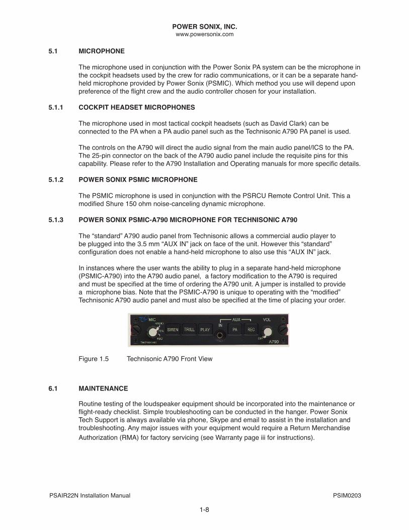
The “standard” A790 audio panel from Technisonic allows a commercial audio player to be plugged into the 3.5 mm “AUX In” jack on face of the unit. However this “standard” configuration does not enable a hand-held microphone to also use this “AUX IN” jack.
In instances where the user wants the ability to plug in a separate hand-held microphone (PSMIC-A790) into the A790 audio panel, a factory modification to the A790 is required and must be specified at the time of ordering the A790 unit. A jumper is installed to provide a microphone bias. Note that the PSMIC-A790 is unique to operating with the “modified” Technisonic A790 audio panel and must also be specified at the time of placing your order.
Figure 1.5 Technisonic A790 Front View
6.1 MAINTENANCE
Routine testing of the loudspeaker equipment should be incorporated into the maintenance or flight-ready checklist. Simple troubleshooting can be conducted in the hanger. Power Sonix Tech Support is always available via phone, Skype and email to assist in the installation and troubleshooting. Any major issues with your equipment would require a Return Merchandise Authorization (RMA) for factory servicing (see Warranty page iii for instructions).
POWER SONIX, INC.www.powersonix.com
PSAIR22n Installation Manual PSIM0203
1-9
6.1.1 AMPLIFIER CHECKS
When normal operation of the PSAIR22n is impaired the following possibilities should be checked with respect to the amplifier:
1. Press the “Press To Test” (PTT) light to make sure power is available (if using the Power Sonix Remote Control Unit PSRCU)2. Check the input Polarity of the DC power supply (on the power cable coming into the PSAIR22n or in the case of the PSAIR22nS, to the PSAMP600 or PSAMP800). Make sure sufficient voltage is available, and that excessive voltage is not applied; (Voltage reading should be between 24-32 volts dC) 3. Check all cables for shorts or opens. dC resistance on the speaker drivers should be approximately 1.8 ohms per driver. 4. If using auxiliary 28V battery, check connection/cables. The PTT light does not indicate until pressed.5. If using PSRCU, turn Power Switch off. PTT light does not indicate until pressed.6. Check dC power to cockpit audio controller. If using PSRCU Remote Control Unit, the PTT light will not indicate normally or when pressed if no power is available.7. Make sure the signal source is not shorted or connected to any noise source.8. The Amplifier may require factory maintenance. Note that the amplifier will automatically reset when reapplying power after a fault condition due to a short is experienced.
6.1.2 POWER SuPPLY CHECKS
The power supplied to the PSAIR22N or to the PSAMP600/800 by the aircraft DC power buss or by an auxiliary 28VDC battery should measure between 24 and 32 volts unloaded and l/2 to l volt lower under load. Check for the proper polarity.
6.1.3 LOuDSPEAKER AND CABLE CHECKS
Testing of loudspeakers and cables may, to some extent, be done visually. All connections should be free from dirt, moisture and open or shorted conditions. All receptacle threads should be completely engaged. A continuity meter may be used to establish the state and correctness of wiring. An ohmmeter touched across the loudspeaker inputs should cause an audible click sound.
6.1.4 PRECAuTIONS IN MAINTENANCE
To avoid serious damage to system components while undergoing troubleshooting or testing, please read these warnings carefully before initiating test procedures.
CAUTION: Do not operate the system from an inadequate power supply or a shop supply, giving rise to high voltage transients.
CAUTION: A grounded test probe from an AC powered meter or Scope placed across the output will short the output to ground and trigger the shutdown circuitry. All test equipment should be isolated from ground potential.
6.1.5 AMPLIFIER/SPEAKER MAINTENANCE
The amplifier and speakers should be kept clean and free from exposure to static charge accumulation and debris. There are no serviceable parts inside our Class d amplifiers.

POWER SONIX, INC.www.powersonix.com
PSAIR22n Installation Manual PSIM0203
1-10
CAUTION: Tampering with the amplifier board itself will void your warranty.
Speaker Driver Maintenance - No maintenance of the compression speaker driver is required. Should a driver fail while under warranty, please return it to Power Sonix for replacement. If out of warranty, please call Power Sonix to purchase a new driver. We recommend having 2 spare speaker drivers (Part # PS-D4Z) for quick replacement on-site if ever needed.
6.1.6 SPEAKER DRIvER CHECKS & REPLACEMENT
A compression driver may fail due to several causes:
1) The coil or its terminals may short to the mounting and cause the amplifier to cut off. This is apparent (once the leads of the suspected driver are separated from other drivers of the speaker assembly) by a continuity test between the driver leads.2) A voice coil short (not likely) showing zero ohm between voice coil leads will also cause the amplifier to cut off.3) A voice coil open-circuit (more likely) will show with an ohmmeter check between leads. no sound will result when the ohmmeter is applied.4) A noisy driver results when the voice coil rubs against the magnetic pole pieces. Noise can best be localized to a single driver unit by connecting each unit singly and energizing each with the amplifier output.
Check each driver for a short or an “open”. A short is evidenced by less than 1 ohm resistance and an “open” by any resistance over 3 ohm. The correct reading should be approximately 1.8 ohms per driver.
When replacing a faulty driver in your PSAIR22N, temporary disassembly of the re-entrant tip and horn will be necessary to gain access to the y-throat adapter and drivers. Disconnect the leads before unscrewing any driver. Be sure to reconnect the leads to the terminals when re-assembling the speaker assembly. Observe the color code to preserve the speaker polarity:
RED WIRE TO #1 TERMINAL, BLACK WIRE TO #2 TERMINAL
6.1.7 RESETTING PROTECTIvE CIRCuIT The amplifier board inside the PSAIR22n series enclosure, the PSAMP600 and the PSAMP800 amplifier are designed with self-protecting circuitry to interrupt the operation whenever harmful conditions exist which might endanger the amplifier components.
Such a condition might be an excessive load current or an output short. once the protective circuit is activated, the flow of power is stopped in the affected channel and no further operation is possible without corrective action. If the trouble was due to a temporary or transitory cause, operation may be resumed by simply turning the power switch “OFF” on the 3rd party PA audio controller or our PSRCU Remote Control Unit, wait 5 seconds to allow the internal circuitry to reset, then turn back to “on”.
The Power FETs of this system are subject to damage when exposed to excessive heat, voltage, and current for even short periods of time. The design incorporates a protective circuit which disables the amplifier when safe operating currents are exceeded.
POWER SONIX, INC.www.powersonix.com
PSAIR22n Installation Manual PSIM0203
1-11
REVDATE USER
8
A
FNAME
B
76
5
C
8
D
76
5
DAT
E:
43
2SCA
LE
SIZE
DW
G N
O.
SHEE
T
1
REV
AB
43
2ZO
NE
REV
C
1RE
VISI
ON
S
DES
CRIP
TIO
N
D
APP
ROVE
DD
ATE B-
0013
05
PSA
IR22
N L
INE
DRA
WIN
G
POW
ER S
ON
IX IN
C.
NTS
1 O
F 1
ENG
.
DRA
WN
BY
CHEC
KED
:
:
:
4-16
-13
MJG
MJG
SH
PSA
IR22
N P
AN
11.7
50
9.75
0
L C
6.50
0
28VD
CRE
MO
TE
PSA
IR22
N
CON
NEC
TOR
M
ATIN
G C
ON
N. M
FG P
ART
#
C
LAM
P PA
RT #
REM
OTE
POW
ER
MS3
106A
16-1
1P
M
S305
7-8A
MS3
106A
16S-
1P
M
S305
7-8A
WEE
P H
OLE
S D
OW
N5.
800
7.87
0
FRO
NT
VIEW
SID
E VI
EW
13.0
00
SERI
ES 3
9/10
010
TIG
ER D
RYLA
C W
HIT
EM
at'l:
505
2-H
32, .
090
THK
drawing 1.1 PSAIR22n Series Enclosure
POWER SONIX, INC.www.powersonix.com
PSAIR22n Installation Manual PSIM0203
1-12
REVDATE USER
8
A
FNAME
B
76
5
C
8
D
76
5
FSCM
NO
.
43
2SC
ALE
SIZE
SHEE
T
1
REV
AB
43
2
ZON
ERE
V
C
1RE
VISI
ON
S
DES
CRIP
TIO
N
D
APP
ROVE
DD
ATE
Dat
eD
raw
n by
:
Eng.
by:
Chec
ked
by:
N.T
.S.
1 of
1
DW
G N
O.
APOW
ER S
ON
IX IN
C.SU
PPO
RT P
LATE
PS-
SUPR
T-N
MJG
MJG SH
3-5-
12
B-00
0196
REQ
'D 2
EAC
H P
ER A
SSY.
C'BO
RE .4
06 D
IA. T
O .1
25 D
EPTH
DRI
LL .1
71 D
IA. 8
PL'S
(TYP
)
1/2-
13N
C TH
RUD
RILL
AN
D TA
P
3-5-
12
3-5-
12
�0.5
00
0.50
0
1.00
01.
500
2.00
02.
250
3.50
04.
750
5.00
05.
500
6.00
06.
500
7.00
0
0.25
01.
500
1.70
32.
250
3.00
0
0.30
00.
500
�0.1
71
�0.4
06
45°
SERI
ES 3
9/10
010
TIG
ER D
RYLA
C W
HIT
EBu
g Re
ady
For P
aint
Smoo
th, G
rain
er o
r Jitt
er
MAT
'L 3
.0"
X 7
.0"
X 0.
5" B
AR
STO
CK60
61-T
6 A
LUM
INU
M
drawing 1.2 PS-SUPRT-n Support Plate For Mounting PSAIR22n Series Speakers
POWER SONIX, INC.www.powersonix.com
PSAIR22n Installation Manual PSIM0203
1-13
REVDATE USER
8
A
FNAME
B
76
5
C
8
D
76
5
FSCM
NO
.
43
2SC
ALE
SIZE
SHEE
T
1
REV
AB
43
2
ZON
ERE
V
C
1RE
VISI
ON
S
DES
CRIP
TIO
N
D
APP
ROVE
DD
ATE
Dat
eD
raw
n by
:
Eng.
by:
Chec
ked
by:
N.T
.S.
1 of
1
DW
G N
O.
APOW
ER S
ON
IX IN
C.
B-00
1305
-MA
N
PJG
MJG PF
2-13
-14
PSXX
X22N
MAT
ING
CO
NN
. PA
RT #
'S
54-C
O-0
46
POW
ER S
ON
IX P
ART
#
(CLA
MP)
SPEA
KER
55-C
O-0
14
CABL
E M
ATIN
G C
ON
NEC
TOR
MS3
057-
8A
MS3
102R
16-1
1P
MFG
. PA
RT #
6-29
-13
2-14
-14
MS3
102R
16-1
1S
28VD
CRE
MO
TESP
KR
A B
54-C
O-0
32
POW
ER S
ON
IX P
ART
#
(CLA
MP)
(CLA
MP)
TO 2
8 VD
C PO
WER
BU
SS
REM
OTE
55-C
0-01
4
55-C
O-0
14
54-C
O-0
46
CABL
E M
ATIN
G C
ON
NEC
TOR
MS3
057-
8A
MS3
106E
16S-
1P
MS3
057-
8A
MS3
106R
-16-
11P
MFG
. PA
RT #
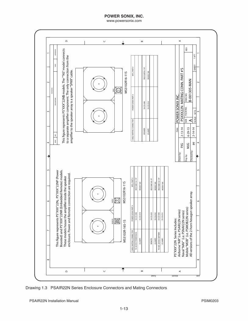
This
�gu
re re
pres
ents
PS”
XXX”
22N
S m
odel
s. Th
e “”
NS”
mod
el c
onne
cts
to a
sep
arat
e am
pli�
er c
ompo
nent
. The
onl
y co
nnec
tion
from
the
ampl
i�er
to th
e sp
eake
r arr
ay is
a s
peak
er “S
PKR”
cab
le.
PS”X
XX”2
2N S
erie
s In
clud
es:
Airb
orne
“AIR
” (i.e
. PSA
IR22
N s
erie
s)
Nav
al “N
AV”
(i.e.
PSN
AV22
N s
erie
s)
Mob
ile “M
OB”
(i.e
. PSM
OB2
2N s
erie
s)
All
vers
ions
of t
he 2
-hor
n he
xago
n sp
eake
r arr
ay.
This
�gu
re re
pres
ents
PS”
XXX”
22N
, PS
”XXX
”22N
P (P
ower
Bo
oste
d) a
nd P
S”XX
X”22
NR
(Em
bedd
ed R
emot
e) m
odel
s.Th
ese
mod
els
hous
e th
e am
pli�
er in
side
the
spea
ker
encl
osur
e. P
ower
and
Rem
ote
conn
ectio
n ar
e re
quire
d.
MS3
102R
-16S
-1S
MS3
102R
16-1
1S
TO A
LT. 2
8 VD
C BA
TTER
Y
(CLA
MP)
54-C
O-0
46
55-C
0-01
4
MS3
106R
-16-
11P
MS3
057-
8A
drawing 1.3 PSAIR22n Series Enclosure Connectors and Mating Connectors
POWER SONIX, INC.www.powersonix.com
PSAIR22n Installation Manual PSIM0203
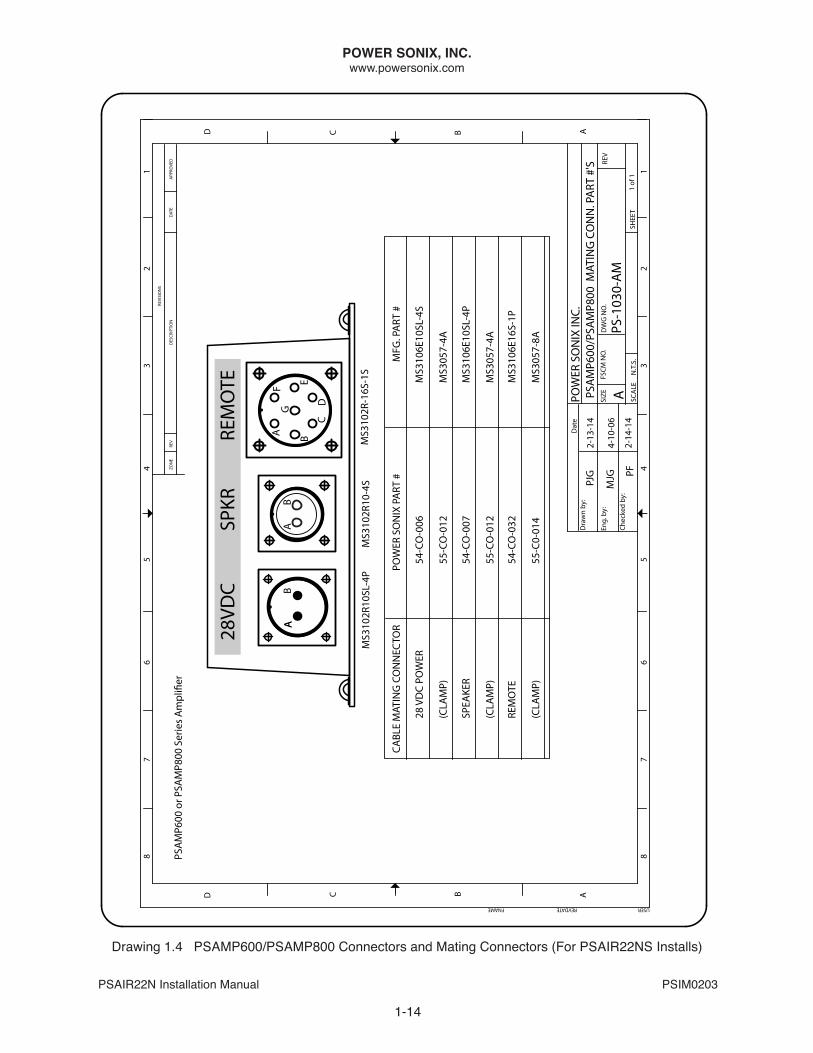
drawing 1.4 PSAMP600/PSAMP800 Connectors and Mating Connectors (For PSAIR22nS Installs)
1-14
REVDATE USER
8
A
FNAME
B
76
5
C
8
D
76
5
FSCM
NO
.
43
2SC
ALE
SIZE
SHEE
T
1
REV
AB
43
2
ZON
ERE
V
C
1RE
VISI
ON
S
DES
CRIP
TIO
N
D
APP
ROVE
DD
ATE
Dat
eD
raw
n by
:
Eng.
by:
Chec
ked
by:
N.T
.S.
1 of
1
DW
G N
O.
APOW
ER S
ON
IX IN
C.
PS-1
030-
AM
PJG
MJG PF
2-13
-14
PSA
MP6
00/P
SAM
P800
MAT
ING
CO
NN
. PA
RT #
'S
PSA
MP6
00 o
r PSA
MP8
00 S
erie
s A
mpl
i�er
54-C
O-0
32
54-C
O-0
07
POW
ER S
ON
IX P
ART
#
(CLA
MP)
(CLA
MP)
(CLA
MP)
28 V
DC
POW
ER
REM
OTE
SPEA
KER
55-C
0-01
4
55-C
O-0
12
55-C
O-0
12
54-C
O-0
06
CABL
E M
ATIN
G C
ON
NEC
TOR
MS3
057-
8A
MS3
106E
16S-
1P
MS3
057-
4A
MS3
106E
10SL
-4P
MS3
057-
4A
MS3
106E
10SL
-4S
MFG
. PA
RT #
4-10
-06
2-14
-14
28VD
C
SPK
R
REM
OTE
AAB
AB
A B
CD
EFG
MS3
102R
10SL
-4P
MS3
102R
10-4
SM
S310
2R-1
6S-1
S
POWER SONIX, INC.www.powersonix.com
PSAIR22n Installation Manual PSIM0203
1-15
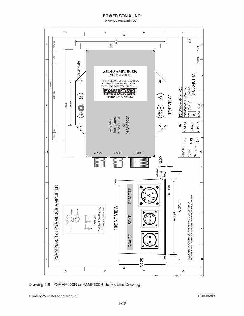
drawing 1.5 PSAMP600 or PAMP800 Series Line drawing
REVDATE USER
8
A
FNAME
B
76
5
C
8
D
76
5
FSCM
NO
.
43
2SC
ALE
SIZE
SHEE
T
1
REV
AB
43
2
ZON
ERE
V
C
1RE
VISI
ON
S
DES
CRIP
TIO
N
D
APP
ROVE
DD
ATE
Dat
eD
raw
n by
:
Eng.
by:
Chec
ked
by:
N.T
.S.
1 of
1
DW
G N
O.
APOW
ER S
ON
IX IN
C.PS
AM
P600
and
PSA
MP8
00 L
ine
Dra
win
g
B-00
0401
-M
PJG
MJG SH
2-14
-07
2-14
-07
2-14
-07
7.40
20
3.05
00
Base
Pla
te
6.20
50
5.45
50
AUDIO AMPLIFIERTYPE PSAMP600
INPUT VOLTAGE 28 VDCOUTPUT CURRENT 30 AMPS.OUTPUT POWER 600 WATTS
MARTINSBURG, WV. USA
28VDC REMOTESPKR
Am
pli�
erEn
clos
ure:
PSA
MP6
00or
PSA
MP8
00
FRO
NT
VIEW
28VD
C
SPKR
R
EMO
TE
4.72
4
0.09
6.20
5
2.20
5
TOP
VIEW
AAB
AB
A B
CD
EFG
Ø0.
375
Ø0.
168
0.28
6
Ø0.
290
TOP
VIEW
SID
E VI
EW
Slid
e La
tch
Stee
l Bus
hing
TOLE
RAN
CE: +
/- .0
05 IN
CHES
PSA
MP6
00 o
r PSA
MP8
00 S
ERIE
S A
MPL
IFIE
RS
NO
TE:
Wat
ertig
ht g
aske
t sea
ls e
nclo
sure
lid
to th
e en
clos
ure
box.
Encl
osur
e Ty
pe: H
amm
ond
1590
DBK
with
cus
tom
hol
es d
rille
d.
Box
Lid
Base
Pla
te
Gas
ket
POWER SONIX, INC.www.powersonix.com
PSAIR22n Installation Manual PSIM0203
1-16
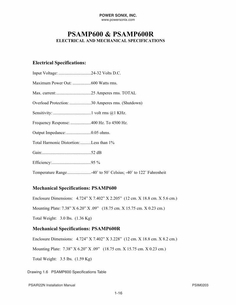
PSAMP600 & PSAMP600R ELECTRICAL AND MECHANICAL SPECIFICATIONS
Electrical Specifications: Input Voltage: ..............................24-32 Volts D.C. Maximum Power Out: .................600 Watts rms. Max. current:................................25 Amperes rms. TOTAL Overload Protection: ....................30 Amperes rms. (Shutdown) Sensitivity: ...................................1 volt rms @1 KHz. Frequency Response: ...................400 Hz. To 4500 Hz. Output Impedance:.......................0.05 ohms. Total Harmonic Distortion:..........Less than 1% Gain:.............................................52 dB Efficiency:....................................95 % Temperature Range......................-40˚ to 50˚ Celsius; -40˚ to 122˚ Fahrenheit Mechanical Specifications: PSAMP600 Enclosure Dimensions: 4.724” X 7.402” X 2.205” (12 cm. X 18.8 cm. X 5.6 cm.) Mounting Plate: 7.38” X 6.20” X .09” (18.75 cm. X 15.75 cm. X 0.23 cm.) Total Weight: 3.0 lbs. (1.36 Kg) Mechanical Specifications: PSAMP600R Enclosure Dimensions: 4.724” X 7.402” X 3.228” (12 cm. X 18.8 cm. X 8.2 cm.) Mounting Plate: 7.38” X 6.20” X .09” (18.75 cm. X 15.75 cm. X 0.23 cm.) Total Weight: 3.5 lbs. (1.59 Kg)
Drawing 1.6 PSAMP600 Specifications Table
POWER SONIX, INC.www.powersonix.com
PSAIR22n Installation Manual PSIM0203
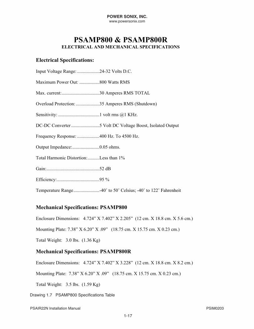
Drawing 1.7 PSAMP800 Specifications Table
PSAMP800 & PSAMP800R ELECTRICAL AND MECHANICAL SPECIFICATIONS
Electrical Specifications: Input Voltage Range: ...................24-32 Volts D.C. Maximum Power Out: .................800 Watts RMS Max. current:................................30 Amperes RMS TOTAL Overload Protection: ....................35 Amperes RMS (Shutdown) Sensitivity: ...................................1 volt rms @1 KHz. DC-DC Converter ........................5 Volt DC Voltage Boost, Isolated Output Frequency Response: ...................400 Hz. To 4500 Hz. Output Impedance:.......................0.05 ohms. Total Harmonic Distortion:..........Less than 1% Gain:.............................................52 dB Efficiency:....................................95 % Temperature Range......................-40˚ to 50˚ Celsius; -40˚ to 122˚ Fahrenheit Mechanical Specifications: PSAMP800 Enclosure Dimensions: 4.724” X 7.402” X 2.205” (12 cm. X 18.8 cm. X 5.6 cm.) Mounting Plate: 7.38” X 6.20” X .09” (18.75 cm. X 15.75 cm. X 0.23 cm.) Total Weight: 3.0 lbs. (1.36 Kg) Mechanical Specifications: PSAMP800R Enclosure Dimensions: 4.724” X 7.402” X 3.228” (12 cm. X 18.8 cm. X 8.2 cm.) Mounting Plate: 7.38” X 6.20” X .09” (18.75 cm. X 15.75 cm. X 0.23 cm.) Total Weight: 3.5 lbs. (1.59 Kg)
1-17
POWER SONIX, INC.www.powersonix.com
PSAIR22n Installation Manual PSIM0203
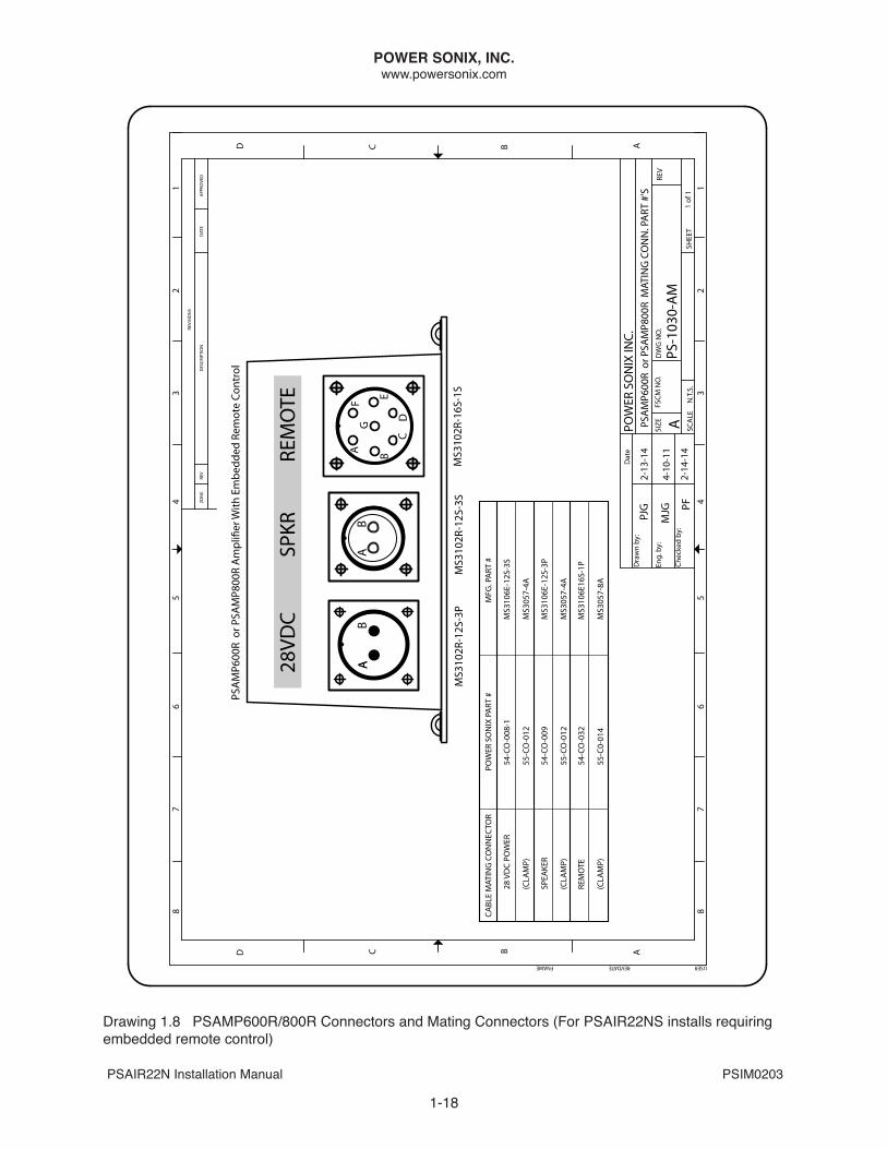
Drawing 1.8 PSAMP600R/800R Connectors and Mating Connectors (For PSAIR22NS installs requiring embedded remote control)
REVDATE USER
8
A
FNAME
B
76
5
C
8
D
76
5
FSCM
NO
.
43
2SC
ALE
SIZE
SHEE
T
1
REV
AB
43
2
ZON
ERE
V
C
1RE
VISI
ON
S
DES
CRIP
TIO
N
D
APP
ROVE
DD
ATE
Dat
eD
raw
n by
:
Eng.
by:
Chec
ked
by:
N.T
.S.
1 of
1
DW
G N
O.
APOW
ER S
ON
IX IN
C.
PS-1
030-
AM
PJG
MJG PF
2-13
-14
PSA
MP6
00R
or P
SAM
P800
R M
ATIN
G C
ON
N. P
ART
#'S
PSA
MP6
00R
or P
SAM
P800
R A
mpl
i�er
With
Em
bedd
ed R
emot
e Co
ntro
l
54-C
O-0
32
54-C
O-0
09
POW
ER S
ON
IX P
ART
#
(CLA
MP)
(CLA
MP)
(CLA
MP)
28 V
DC
POW
ER
REM
OTE
SPEA
KER
55-C
0-01
4
55-C
O-0
12
55-C
O-0
12
54-C
O-0
08-1
CABL
E M
ATIN
G C
ON
NEC
TOR
MS3
057-
8A
MS3
106E
16S-
1P
MS3
057-
4A
MS3
106E
-12S
-3P
MS3
057-
4A
MS3
106E
-12S
-3S
MFG
. PA
RT #
4-10
-11
2-14
-14
28VD
C
SPK
R
REM
OTE
AAB
AB
A B
CD
EFG
MS3
102R
-12S
-3P
MS3
102R
-12S
-3S
MS3
102R
-16S
-1S
1-18
POWER SONIX, INC.www.powersonix.com
PSAIR22n Installation Manual PSIM0203
drawing 1.9 PSAMP600R or PAMP800R Series Line drawing
REVDATE USER
8
A
FNAME
B
76
5
C
8
D
76
5
FSCM
NO
.
43
2SC
ALE
SIZE
SHEE
T
1
REV
AB
43
2
ZON
ERE
V
C
1RE
VISI
ON
S
DES
CRIP
TIO
N
D
APP
ROVE
DD
ATE
Dat
eD
raw
n by
:
Eng.
by:
Chec
ked
by:
N.T
.S.
1 of
1
DW
G N
O.
APOW
ER S
ON
IX IN
C.PS
AM
P800
R Li
ne D
raw
ing
B-00
0401
-M
PJG
MJG SH
2-14
-07
2-14
-07
2-14
-07
7.38
20
3.05
00
Base
Pla
te
6.20
50
5.45
50
AUDIO AMPLIFIERTYPE PSAMP800R
INPUT VOLTAGE 28 VOLTS DC MAX.OUTPUT POWER 800 WATTS MAX.OUTPUT CURRENT 30 AMPS. MAX.
MARTINSBURG, WV. USA
28VDC REMOTESPKR
Am
pli�
erEn
clos
ure:
PSA
MP6
00R
or
PSA
MP8
00R
FRO
NT
VIEW
28VD
C
SPKR
R
EMO
TE
4.72
4
0.09
6.20
5
3.22
8
TOP
VIEW
AAB
AB
A B
CD
EFG
Ø0.
375
Ø0.
168
0.28
6
Ø0.
290
TOP
VIEW
SID
E VI
EW
Slid
e La
tch
Stee
l Bus
hing
TOLE
RAN
CE: +
/- .0
05 IN
CHES
PSA
MP6
00R
or P
SAM
800R
AM
PLIF
IER
Wat
ertig
ht g
aske
t sea
ls e
nclo
sure
lid
to th
e en
clos
ure
box.
Encl
osur
e T
ype:
Ham
mon
d 15
90W
EBK
with
cus
tom
hol
es d
rille
d.
Box
Lid
Base
Pla
te
Gas
ket
1-19

POWER SONIX, INC.www.powersonix.com
PSAIR22n Installation Manual PSIM0203
1-20
This page left blank intentionally.
POWER SONIX, INC.www.powersonix.com
PSAIR22n Installation Manual PSIM0203
1-21
drawing 1.10 Technisonic A790 Interconnect
REVDATE USER
8
A
FNAME
B
76
5
C
8
D
76
5
FSCM
NO
.
43
2SC
ALE
SIZE
SHEE
T
1
REV
AB
43
2
ZON
ERE
V
C
1RE
VISI
ON
S
DES
CRIP
TIO
N
D
APP
ROVE
DD
ATE
Dat
eD
raw
n by
:
Eng.
by:
Chec
ked
by:
N.T
.S.
1 of
1
DW
G N
O.
AA79
0/PS
AIR
22N
INTE
RCO
NN
ECT
MJG
MJG
SH
3-2-
11
PSA
IR22
N
28VD
C
RE
MO
TE
A
BA
BC
DEF G
SEE
LATE
ST T
ECH
NIS
ON
IC A
790
OPE
RATI
NG
25 P
IN D
IN C
ON
NEC
TOR
+ 28
VO
LT D
C PO
WER
NEG
ATIV
E PO
WER
GRO
UN
D
15
PA
PO
WER
CO
NTR
OL
(SH
IELD
ED P
AIR
)
PS-1
012-
C-E2
CON
NEC
TORS
ON
FRO
NT
OF
PSA
MP6
00, P
SAM
P800
or P
SAIR
22N
25
GRO
UN
D
12
AU
DIO
OU
TPU
T (-)
13
AU
DIO
OU
TPU
T (+
)
5
PA
PO
WER
LEV
EL M
ON
ITO
R
2
PA
PO
WER
CO
NTR
OL
Tech
niso
nic
A79
0
3-2-
11
3-2-
11
AN
D IN
STA
LLTI
ON
MA
NU
ALS
@ h
ttp:
//til
.ca
FO
R A
DD
ITIO
NA
L W
IRIN
G D
IREC
TIO
NS
(BLA
CK)
(WH
ITE)
(BLU
E)
(BLA
CK)
(GRE
EN)
(YEL
LOW
)
(ORA
NG
E)
(RED
)Au
dio
Cont
rolle
r
PSA
MP6
00 o
rPS
AM
P800
28VD
CRE
MO
TESP
KR
28VD
CRE
MO
TE
POWER SONIX, INC.www.powersonix.com
PSAIR22n Installation Manual PSIM0203
1-22
drawing 1.11 PSAIR22n Power Cables
PSCBL-DC-XX
Ring Terminals with No. 8-10 Stud
AB
WHITE WHITE
BLACK BLACK
PSCBL-DC1-XX
Connector Military SpecificationMS3106E10SL-4S
Clamp Military SpecificationMS3057-4A
A
B
4" Lead From Jacketto Ring Terminals
To “28VDC”
Power In onPSAMP600 or
PSAMP800 Series (For PSAIR22NS)
To Aircraft DC Power Buss
DC Power Out
AB
WHITE WHITE
BLACK BLACK
To Aircraft DC Power Buss
DC Power Out
Connector Military Specification MS3106R-16-11P
Collar Military Specification MS3057-8A Collar
A
B
To “28VDC”
Power In onPSAIR22N, PSAIR22NP
& PSAIR22NR
Ring Terminals with No. 8-10 Stud
AIRCRAFT POWER CABLES
Ring Terminals with No. 8-10 Stud
AB
WHITE WHITE
BLACK BLACK
PSCBL-DCR1-XX
Connector Military SpecificationMS3106E12S-3S
Clamp Military SpecificationMS3057-4A
A
B
4" Lead From Jacketto Ring Terminals
To “28VDC”
Power In onPSAMP600R or
PSAMP800R Series (For PSAIR22NS)
To Aircraft DC Power Buss
DC Power Out
POWER SONIX, INC.www.powersonix.com
PSAIR22n Installation Manual PSIM0203
1-23
Drawing 1.12 PSAIR22N Auxiliary 28VDC Battery Cables
AB
AB
WHITE WHITE
BLACK BLACK
To 28 VoltBattery
Power OutPS-BAT2-28PB
PSCBL-BAT2-XX
Connector Military Specification MS3106R-16-11P
Connector Military Specification MS3106R16-11S
Collar Military Specification MS3057-8A
Collar Military Specification MS3057-4
To “28VDC”
Power In onPSAIR22N,
PSAIR22NP & PSAIR22NR
AB
AB
WHITE WHITE
BLACK BLACK
To 28 VoltBattery
Power OutPS-BAT-28PB
PSCBL-BAT-XX
Connector Military Specification MS3106R-16-11P
Connector Military Specification MS3106R-12S-3P
Collar Military Specification MS3057-8A
Collar Military Specification MS3057-4
To “28VDC”
Power In onPSAIR22N,
PSAIR22NP & PSAIR22NR
For use with PS-BAT2-28PB
For use with PS-BAT-28PB
AB
AB
WHITE WHITE
BLACK BLACK
Connector Military SpecificationMS3106A10SL-4S
Connector Military SpecificationMS3106A12S-3P
Clamp Military SpecificationMS3057-4A
Clamp Military SpecificationMS3057-4A
To “28VDC”
Power In onPSAMP600 or
PSAMP800 Series (For PSAIR22NS)
PSCBL-BAT1-XX For use with PS-BAT-28PB
AUXILARY 28VDC BATTERY POWER CABLES
AB
AB
WHITE WHITE
BLACK BLACK
To 28 VoltBattery
Power OutPS-BAT2-28PB
Connector Military Specification MS3106A10SL-4S
Connector Military Specification MS3106R16-11S
Collar Military Specification MS3057-4A
Collar Military Specification MS3057-4
To “28VDC”
Power In onPSAMP600 or
PSAMP800 Series (For PSAIR22NS)
For use with PS-BAT2-28PBPSCBL-BAT2A-XX
To 28 VoltBattery
Power OutPS-BAT-28PB
AB
AB
WHITE WHITE
BLACK BLACK
To 28 VoltBattery
Power OutPS-BAT2-28PB
Connector Military Specification MS3106E12S-3S
Connector Military Specification MS3106R16-11S
Collar Military Specification MS3057-4A
Collar Military Specification MS3057-4
To “28VDC”
Power In onPSAMP600R or
PSAMP800R Series (For PSAIR22NS)
For use with PS-BAT2-28PBPSCBL-BAT2R-XX
DEMO KIT AUXILARY 28VDC BATTERY POWER CABLES
POWER SONIX, INC.www.powersonix.com
PSAIR22n Installation Manual PSIM0203
1-24
drawing 1.13 PSAIR22n Remote Audio Cables
ABCDEFG
ABCDEFG
PSCBL-RCU-XX
To “REMOTE”Audio In onPSAIR22N, PSAIR22NP & PSAIR22NR; or in case of
PSAIR22NS, to the PSAMP600 or PSAMP800 amplifier.
Connector Military Specification MS3106E-16S-1P
Collar Military Specification MS3057-8A
To Remote Control Unit
(PSRCU)
Collar Military Specification MS3057-8A
ABCDEFG
PSCBL-RCU-XXA
Connector Military Specification MS3106E-16S-1P
Collar Military Specification MS3057-8A
Connector Military Specification MS3106E-16S-1P
Open Cable To Audio Panel such as Technisonic A790
or cockpit ICS
STANDARD REMOTE CONTROL CABLES
To “REMOTE”Audio In on:PSAIR22N, PSAIR22NP PSAIR22NR;
or in case of PSAIR22NS, to the PSAMP600 or PSAMP800 or
PSAMP600R or PSAMP800R
POWER SONIX, INC.www.powersonix.com
PSAIR22n Installation Manual PSIM0203
.125" Stereo Audio PlugA
B
CAB
RED
SHIELDBLACK
Connector Military Specification MS3106A10SL-4S
Collar Military Specification AN3057-4
To “AUX IN” on
PSRCU Remote Control Unit
For use with PSRCU
To COTS MP3 Player or Audio Device
C
RED
PSCBL-RDR-1A
AUXILIARY AUDIO IN CABLE
SPEAKER CABLE: CONNECTS PSAIR22NS TO AMPLIFIER
PSCBL-SPK-2-XXAB
AB
WHITE WHITE
BLACK BLACK
To “SPK”Speaker connectoron PSAMP600 or PSAMP800 Series
amplifier
Connector Military Specification MS3106E16-11P
Connector Military Specification MS3106E10SL-4P
Collar Military Specification MS3057-4A
Collar Military Specification MS3057-4A
To “SPK”
Speaker connectoron PSAIR22NS
For use with PSAIR22NS
(Black wire is cut off at collar, it has no connection.)
SPEAKER CABLE: CONNECTS PSAIR22NS TO EMBEDDED REMOTE AMPLIFIERS
PSCBL-SPK-2R-XXAB
AB
WHITE WHITE
BLACK BLACK
To “SPK”Speaker connectoron PSAMP600R or PSAMP800R
amplifier
Connector Military Specification MS3106E16-11P
Connector Military Specification MS3106E-12S-3P
Collar Military Specification MS3057-4A
Collar Military Specification MS3057-4A
To “SPK”
Speaker connectoron PSAIR22NS
For use with PSAIR22NS
1-25
Drawing 1.14 PSAIR22N Speaker and Auxiliary Audio-In Cables
POWER SONIX, INC.www.powersonix.com
PSAIR22n Installation Manual PSIM0203
drawing 1.15 PSCbL-RdR-A790
drawing 1.16 PSCbL-RdR-A790M
REVD
ATE
USE
R
8
A
FNA
ME
B
7 6 5
C
8
D
7 6 5
DATE:
4 3 2SCALE
SIZE DWG NO.
SHEET
1
REV
A
B
4 3 2ZONE REV
C
1REVISIONS
DESCRIPTION
D
APPROVEDDATE
B-000434
POWER SONIX INC.
NTS 1 OF 1
ENG.
DRAWN BY
CHECKED:
:
:
3-22-12
MJG
MJG
SH
PSCBL-RDR-A790
PSCBL-RDR-A790
Commercial O�-The-Shelf.125" Stereo Audio Plug
72 in.
2 2 CONDUCTOR WIRE W/ SHIELD 1 LABLE "PSCBL-RDR-A790" 50-LA-006
ITEM DESCRIPTION MFG. PART# PS PART#
R.S. 42-2387A
21
Commercial O�-The-Shelf3.5 mm Stereo Audio Plug
To A790 Aux In Jack To Audio Player
REVD
ATE
USE
R
8
A
FNA
ME
B
7 6 5
C
8
D
7 6 5
DATE:
4 3 2SCALE
SIZE DWG NO.
SHEET
1
REV
A
B
4 3 2ZONE REV
C
1REVISIONS
DESCRIPTION
D
APPROVEDDATE
B-000248
POWER SONIX INC.
NTS 1 OF 1
ENG.
DRAWN BY
CHECKED:
:
:
3-22-12
MJG
MJG
SH
PSCBL-RDR-A790M
PSCBL-RDR-A790M
Right Angle .125" Stereo Audio Plug
5 FOOT
3 2 CONNNECTOR WIRE W/SHIELD
2 LABLE PSCBL-RDR-A790M 50-LA-006
ITEM DESCRIPTION MFG. PART# PS PART#
15-CA-011
2
3
B Cut o� Black Wire; Not UsedC Tinned Shield to Barrel Ground
A Red Wire to TIP
1AB
C
1 1/8" Stereo Plug RS 274-0858
For Recorder InputsAUX Microphone UseA790 Is Wired ForMust Be Used When
Commercial O�-The-Shelf3.5 mm Stereo Audio Plug
To A790 Aux In Jack To Audio Player
1-26

POWER SONIX, INC.www.powersonix.com
PSAIR22n Installation Manual PSIM0203
1-27
THIS PAgE LEFT bLAnK InTEnTIonALLy.
POWER SONIX, INC.www.powersonix.com
PSAIR22n Installation Manual PSIM0203
1-28
REVDATE USER
8
A
FNAME
B
76
5
C
8
D
76
5
FSCM
NO
.
43
2SC
ALE
SIZE
SHEE
T
1
REV
AB
43
2
ZON
ERE
V
C
1RE
VISI
ON
S
DES
CRIP
TIO
N
D
APP
ROVE
DD
ATE
Dat
eD
raw
n by
:
Eng.
by:
Chec
ked
by:
N.T
.S.
1 of
1
DW
G N
O.
A
NAT
AA
22 to
PSA
IR IN
TERC
ON
NEC
T D
IAG
RAM
M
JG
MJG SH
1-5-
06
1-5-
06
1-5-
06
PSA
IR22
N
28VD
C
REM
OTE
A B
A
BC
DEF G
N.A
.T. A
UD
IO C
ON
TRO
LLER
25 P
IN D
MIN
CO
NN
ECTO
R
NEG
ATIV
E PO
WER
GRO
UN
D
AUD
IO O
UT
LO
SWIT
CH P
OW
ER (2
8V) O
UT
619 8
SHIE
LDED
PA
IR
15G
ND
PS-1
012-
B
Dia
gram
goo
d fo
r NAT
Mod
els:
A
A22
-110
/160
/163
/170
**
AA
22-4
92/4
95/5
92/5
94A
A22
-493
AUD
IO O
UT
HI
RED
BLAC
K
** N
OTE
: AA
22-1
10/1
60/1
63/1
70 N
EED
SA
1/4
WAT
T 39
0 O
HM
RES
ISTO
RBE
TWEE
N P
INS
D &
E
YELL
OW
BLU
E/SH
IELD CO
NN
ECTO
RS U
ND
ER H
ORN
PSA
IR42
N
4
5 A
MPS
PSA
IR32
N
3
5 A
MPS
PSA
IR22
N
2
5 A
MPS
PSA
IR12
N
1
5 A
MPS
MO
DEL
MIN
. CIR
CUIT
BRE
AKE
R
CIR
CUIT
BRE
AKE
R
+ 28
VO
LT D
C PO
WER
(WH
ITE)
drawing 1.18 n.A.T. Audio Controller Interconnect To PSAIR22n or PSAMP600
POWER SONIX, INC.www.powersonix.com
PSAIR22n Installation Manual PSIM0203
1-29
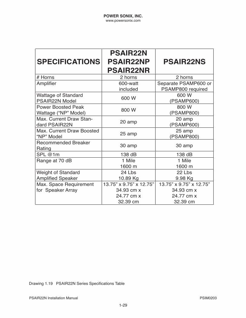
SPECIFICATIONSPSAIR22N
PSAIR22NPPSAIR22NR
PSAIR22NS
# Horns 2 horns 2 hornsAmplifier 600-watt
includedSeparate PSAMP600 or
PSAMP800 requiredWattage of Standard PSAIR22n Model 600 W 600 W
(PSAMP600)Power boosted Peak Wattage (“nP” Model) 800 W 800 W
(PSAMP800)Max. Current draw Stan-dard PSAIR22n 20 amp 20 amp
(PSAMP600)Max. Current draw boosted “nP” Model 25 amp 25 amp
(PSAMP800)Recommended breaker Rating 30 amp 30 amp
SPL @1m 138 db 138 dbRange at 70 db 1 Mile
1600 m1 Mile
1600 mWeight of StandardAmplified Speaker
24 Lbs10.89 Kg
22 Lbs9.98 Kg
Max. Space Requirement for Speaker Array
13.75” x 9.75” x 12.75”34.93 cm x 24.77 cm x 32.39 cm
13.75” x 9.75” x 12.75”34.93 cm x 24.77 cm x 32.39 cm
Drawing 1.19 PSAIR22N Series Specifications Table
POWER SONIX, INC.www.powersonix.com
PSAIR22n Installation Manual PSIM0203
Contact Information:For sales, customer service or technical assistance, call us at our headquarters in Martinsburg, WV, USA at +1 304-267-7560. our fax number is +1 304-267-8691.
Emails for company departments are as follows:
Sales: [email protected] Service: [email protected] Support: [email protected]
1-30
www.powersonix.com