Embed Size (px)
Citation preview

Section 6 Water
6.0 WATER SUPPLY CONTENTS
6.0 WATER SUPPLY ...................................................................................................................................... I 6.1 Introduction ................................................................................................................................. 6-1
6.1.1 Objectives ...................................................................................................................... 6-1 6.1.2 Alteration to Existing Structure ...................................................................................... 6-1 6.1.3 ICMP and WIA’s ............................................................................................................ 6-1
6.2 Design ........................................................................................................................................ 6-1 6.2.1 Design Life .................................................................................................................... 6-1 6.2.2 Approved Materials ....................................................................................................... 6-1 6.2.3 System Design .............................................................................................................. 6-2 6.2.4 Clearances .................................................................................................................... 6-4 6.2.5 Shared Trenches ........................................................................................................... 6-5 6.2.6 Pipeline Restraint .......................................................................................................... 6-5 6.2.7 Hydrants ........................................................................................................................ 6-6 6.2.8 Valves ............................................................................................................................ 6-6 6.2.9 Connections .................................................................................................................. 6-7
6.3 Construction ............................................................................................................................. 6-11 6.3.1 Pipe Laying .................................................................................................................. 6-11 6.3.2 Setting Out of Water Mains in Road Reserve ............................................................. 6-11 6.3.3 Jointing ........................................................................................................................ 6-11 6.3.4 Valves .......................................................................................................................... 6-11 6.3.5 Valve and Hydrant Boxes ............................................................................................ 6-11 6.3.6 Connections ................................................................................................................ 6-13 6.3.7 Embedment, Backfilling and Reinstatement ............................................................... 6-13 6.3.8 Pressure Testing ......................................................................................................... 6-14 6.3.9 Disinfection and Flushing ............................................................................................ 6-14 6.3.10 Water Mains to be Kept Charged ................................................................................ 6-16 6.3.11 Abandoned Water mains ............................................................................................. 6-16
LIST OF APPENDICES Appendix A Forms and Checklists ............................................................................................................... 6-17 Appendix B Drawings .................................................................................................................................. 6-18 LIST OF TABLES Table 6-1:Standard Pipe Details ..................................................................................................................... 6-2 Table 6-2: Standard Pipe Configuration ......................................................................................................... 6-2 Table 6-3: Rider Mains ................................................................................................................................... 6-2 Table 6-4: Minimum Cover Requirements ...................................................................................................... 6-3 Table 6-5: Valve description ........................................................................................................................... 6-7 Table 6-6: Valve and Hydrant Tolerances .................................................................................................... 6-12 Table 6-7: Disinfection Dosing Requirements .............................................................................................. 6-15 Table 6-8: Forms and Checklists .................................................................................................................. 6-17 Table 6-9: Drawing Register ......................................................................................................................... 6-18

Section 6 Water
Page 6-1 Last Updated4 December 2012
6.1 Introduction
This section sets out requirements for the design and construction of drinking water supply systems for land development and subdivision. It covers the design of water pipes up to and including 225 mm diameter. All bulk mains and reservoirs will require specific design and are excluded from this specification.
6.1.1 Objectives
The design of any water network shall ensure an acceptable water supply for each property, including fire flows, by providing either a:
a) water main allowing an appropriate point of supply to each property
b) service connection from the main to each property
The Designer shall consider:
a) The hydraulic adequacy of the system
b) The ability of the water system to maintain acceptable water quality
c) The structural strength of water system components to resist applied loads
d) The requirements of SNZ PAS 4509
e) Environmental requirements
f) The environmental and community impact of the works
g) The ‘fit for purpose’ service life for the system
h) Optimising the ‘whole of life’ cost;
i) Each components resistance to internal and external corrosion or degradation
j) Integrated three waters management
6.1.2 Alteration to Existing Structure
Any alteration of the existing water network to achieve compliance of the new development, to Council’s standards, shall be at no cost to Council.
6.1.3 ICMP and WIA’s All design shall be as per an approved ICMP or WIA.
6.2 Design
6.2.1 Design Life All water supply systems shall be designed and constructed for an asset life of at least 100 years. Some components such as pumps, metering, control valves, and control equipment may require earlier renovation or replacement.
6.2.2 Approved Materials Refer to the approved materials Section 9.

Section 6 Water
Page 6-2 Last Updated4 December 2012
6.2.3 System Design Generally water mains shall be designed with sufficient capacity to cater for all existing and predicted development within the area to be serviced.
Watermains shall not be located on private property unless approval from Council has been granted.
The water demand allowance in the subdivision design shall include provision for:
a) Population targets
b) The area to be serviced
c) Individual properties proposed
d) Proposed land use (zoning)
e) Design pressures including the requirements of SNZ PAS 4509
For general application, Council has standard sizes for all water mains as shown the table below. Pipe sizes other than those listed above shall not be used on the Council water supply network. All bulk mains will require specific design.
Table 6-1:Standard Pipe Details
Size and Material
Connections Various Sizes, MDPE
Rider Mains 63 mm OD MDPE (DN 50), PN12
Principal Mains DN 150 PVC, PN12
Trunk Mains DN 250, DN 300, DN 375 PVC
Table 6-2: Standard Pipe Configuration
Area Configuration
Residential Principal main on one side of the road and a rider main on the other - refer Table 6-1.
Industrial, Commercial and Arterial or Dual Carriageway Streets
Principal main on both sides of the road
All Other Areas Principal main on one side of the road
Table 6-3: Rider Mains
Pressure Maximum Number of Dwelling Units
One ended supply Two ended supply
Medium Pressure (located below 45 m Moturiki Datum)
15 30
Low Pressure (located above 45 m Moturiki Datum)
7 15
Where the number of dwelling units exceeds the maximum number for a rider main, a principal main shall be installed on both sides of the road.

Section 6 Water
Page 6-3 Last Updated4 December 2012
6.2.3.1 General Design Notes
a) By convention, PVC pressure pipes in New Zealand are usually referred to by their nominal internal diameter (i.e. DN 50, 100, 150 etc.) whereas the equivalent size ISO dimension PE pipes are usually referred to and specified by their nominal outside diameter (i.e. 63, 125, 180 OD).
b) In any instance where an external diameter is shown on a drawing of specified it shall be annotated “OD”. Dimensions in absence of either “ID” or “OD” shall be assumed by Council to refer to an internal diameter.
c) To support future growth Council may require mains to be upsized – refer to the approved ICMP or WIA and Council for details
d) All undersized mains associated with a development shall be upsized to the minimum requirements at no cost to Council.
e) The design of the reticulation shall be such that a water supply connection can be readily provided to the ‘front’ of each allotment (i.e. where the driveway will be installed) and no connection passing under a roadway.
f) Dead end water main design should be avoided by the provision of linked mains or looped mains. Staged developments shall terminate with a temporary fire hydrant or flushing valve.
g) Drinking water supply systems shall be designed and equipped to prevent backflow. The location and operation of hydrants, air valves and scours shall ensure no external water enters the system through negative pressures from normal operation.
h) The standard position of water mains in the Transportation Corridor shall be in the roadway berm, parallel to and 2.0m from the (average) property boundary in accordance with NAUAG. Where water mains cannot be laid in the standard alignment, an alternative alignment showing the relative locations of all services shall be designed and proposed with the engineering plans.
i) Water mains shall not transverse steep gradients without specific acceptance of design plans.
j) Water main crossings of roads, railway lines, and underground services shall, as far as practicable, be at right angles. Mains should be located and designed to minimise maintenance and crossing restoration. At road intersections, 90 degree tees or 90 degree bends are required.
k) Root boxes will need to be provided for new developments to protect mains from trees. Refer to the Landscaping Section. For retrofit situations refer to Council for advice.
l) Minimum cover requirements are shown in Table 6-4. The sections of main adjacent to a carriageway crossing shall be gradually deepened, to allow the required cover under the carriageway without the provision of vertical bends. Similar provision shall be made to ensure the necessary cover over valve and hydrant spindles.
Table 6-4: Minimum Cover Requirements
Situation Minimum Cover (m)
Principal mains and rider mains in berm 750
Principal mains and rider mains under carriageways 900
Service connection pipes 350

Section 6 Water
Page 6-4 Last Updated4 December 2012
Trunk mains 900
6.2.3.2 Rural Area Design Notes
a) Rural restricted feed water supply schemes are not required to provide fire fighting capacity
b) Individual rainwater tanks, individual privately owned bores, wells or restricted supply, may adequately serve isolated small subdivisions in rural settings (Future Urban Zone Proposed District Plan)
c) Where rain water tanks are provided for the purpose of rain water harvesting and reuse within the building, the design for domestic demand can be reduced to 225 litres/person/day
6.2.3.3 Fire Fighting Supply
Council’s standard design meets the FW2 fire fighting requirements at the street boundary for residential areas and provides for FW3 for other zones. Where additional fire fighting coverage is required, private storage shall be designed to comply with the requirements SNZ PAS 4509:2008: New Zealand Fire Service Fire Fighting Water Supplies Code of Practice.
The minimum requirements are based on SNZ PAS 4509:2008, however this may need to be increased to ensure security of supply for operational purposes within the premise. Council recommends all commercial and industrial premises have 24 hours of operational storage.
6.2.3.4 Structural Design
The pipeline installation shall be specifically designed to resist structural failure. The design shall be in accordance with AS/NZS 2566 including Supplement 1. Details of the final design requirements shall be shown on the drawings.
6.2.3.5 Above-ground Water Mains
Above-ground water mains should be avoided. If necessary, specific engineering design will be required and approved by Council.
6.2.3.6 Non-Council Supply
In order to meet the requirements of the Building Act and Health Act in all developments where Council is not obligated to supply water, details of the source, capacity and quality of the existing and proposed water supply shall be provided to Council.
Where any lot is connected to Council’s water supply network and uses an alternative supply of water for any purpose, those alternative supplies shall be installed with appropriate backflow prevention devices. Those devices are to be maintained at all times to prohibit cross contamination of the Council’s system. Reference shall be made to the requirements set out in the HCC Water Supply Bylaw.
6.2.3.7 Contaminated Land
Refer Section 2 – Earthworks and Geotechnical Requirements.
6.2.4 Clearances Clearance from underground services shall be as per NZS 4404:2010 Section 5.3.7.9.

Section 6 Water
Page 6-5 Last Updated4 December 2012
6.2.5 Shared Trenches Where shared trenching is approved by Council and all affected utility owners, a detailed design shall be submitted for approval by those parties and shall include:
a) Relative location of services (horizontal and vertical) in the trench
b) Clearances from other services
c) Pipe support and trench fill material specifications
d) Trench marking
e) Services’ location from property boundaries
f) Any limitations on future maintenance
g) Special anchoring requirements, such as for bends and tees
6.2.5.1 Alteration to Existing Infrastructure
Any alteration of the existing water supply reticulation (upgrading, relocation and lowering of water mains and other water supply elements) required for compliance of the new development to Council’s standards shall be at no cost to Council.
6.2.6 Pipeline Restraint Anchorage shall be provided at bends, tees, reducers, valves and dead ends where necessary.
6.2.6.1 Thrust Blocks
The design of thrust blocks shall be based on the maximum test pressure.
Thrust blocks shall be designed to resist the total unbalanced thrust and transmit all loads to the adjacent ground. Calculation of the unbalanced thrust shall be based on the maximum design pressure, except that the maximum value used shall be 75 kPa.
Typical contact areas for selected soil conditions and pipe sizes are shown in NZS 4404:2010 Appendix B drawings WS – 004 and WS – 005. Thrust blocks for temporary infrastructure shall be designed to the requirements for permanent thrust blocks.
6.2.6.2 Anchor Blocks
The design of anchor blocks shall be based on the allowable bearing capacity of the site soil conditions, except that the maximum value used shall be 75 kPa. The inner face of the block shall not be of a lesser thickness than the diameter of the fittings, and shall be constructed so as not to impair access to the bolts on the fittings. Concrete shall have a minimum compressive strength of 17.5 MPa at 28 days.
Anchor blocks are designed to prevent movement of pipe bends in a vertical direction. They consist of sufficient mass concrete to prevent pipe movement. See NZS 4404:2010 Appendix B drawing WS – 005
6.2.6.3 Restrained Joint Water Mains
Commercially available, mechanically restrained, jointing systems may be used to avoid the need for thrust and anchor blocks subject to the approval of Council. Approval for the use of these systems must be obtained from Council prior to installation.

Section 6 Water
Page 6-6 Last Updated4 December 2012
6.2.7 Hydrants Hydrants are installed in reticulation systems for fire fighting and/or operational purposes. Operational purposes may include mains flushing, chlorination, and to allow the escape of air during charging and the release of water during the dewatering of the main.
6.2.7.1 Hydrant Design
a) The preferred location for hydrants is in the road berm rather than the carriageway. However, NZS 4509 requires hydrants not to be located within 6.0m of any exiting or proposed building. Where this contradiction exists in a design, advice should be sort from Council
b) Hydrants shall not be fitted to any main less than DN 150
c) Hydrant risers shall be used, or the water main laid deeper, where necessary to ensure the top of the spindle is between 50mm and 200mm below the fire hydrant lid
d) Hydrants shall be spaced at intervals not exceeding the following
i. Residential areas 135m ii. Commercial and Industrial areas 90m (on each side of the road)
e) In a cul-de-sac or in other terminal roads, the last hydrant shall be not more than 65m from the end of the road measured at the property boundary
f) Where houses or residential units are situated on private ways, there shall be a hydrant within 135m of any house or unit
g) Hydrants should be located clear of vehicle crossings (in the grassed roadway berm). In new developments, where formation of vehicle crossings are deferred until construction of the buildings, hydrants should be located in the centre of the street frontage to avoid the most likely location of the vehicle crossings alongside boundaries
h) In addition to hydrant spacing for fire fighting, hydrants shall be positioned at high points to facilitate flushing air from the mains and at low points to facilitate flushing sediment from the mains
i) Hydrants shall be placed within hydrant boxes designed in accordance with the Drawing D6.3. The location of the hydrants shall be marked in accordance with the requirements set out in SNZ PAS 4509:2008
j) Flushing points (valve or hydrant) shall be installed at the end of DN50 / 63 OD rider mains refer Drawing D6.1)
6.2.8 Valves Valves shall be installed to permit isolation of sections of the pipe network for maintenance and operational purposes. The spacing and location of valves shall be such as to limit the number of dwellings affected by a shutdown to no more than 30.
Valves shall be provided as follows.
a) Each side of arterial roads and railway crossings
b) Adjacent to street intersections, having regard to the safety requirements for operational access
c) On at least two legs leading from each tee intersection
d) A maximum spacing of 250m

Section 6 Water
Page 6-7 Last Updated4 December 2012
Subject to these considerations, valve numbers shall be minimised.
Attention should also be given to the location of the valve in particular:
a) Ensure that the valve can be operated safely, i.e. traffic management requirements
b) Avoid clustering of surface fittings in the footpath at intersections.
c) The design shall ensure valve positioning places them outside of the sealed carriageway, behind the kerb and in the grass berm.
d) Valves shall be installed next to other fittings such as tees or bends where possible. Refer drawing D6.2 for details.
6.2.8.1 Valve Types
Table 6-5: Valve description
Valve Type
Sluice Valves
Sluice valves shall be used on principal mains. The valves shall be resilient seated, anticlockwise closing with a non-rising spindle to NZS/AS 2638.2:2011 (pressure rated PN16). All valves shall be thermal-bonded polymeric coated to NZS/AS 4158:2003
Gate Valves (also known as Peet valves)
Gate valves DN 50 or less shall be clockwise closing with cast iron T bar handles. Valves to be manufactured to BS 5154 or AS 1628
Air/Vacuum Valves and Scour Valves
Shall only be used when required by Council. Air valves and Scour valves shall be specifically designed to suit the installed location
Butterfly Valves Butterfly valves shall only be used with the approval of Council
6.2.9 Connections 6.2.9.1 General
Before connection to the water network, the Council connection process and forms shall be completed by the applicant and acceptance provided. This applies to:
• All new connections and disconnections from private property.
• All new connections of new water mains to be tied into the existing public sewer.
For all connections where volumes greater than 15m3 are required, compliance HCC’s Resource Consent 113941 (Condition No’s. 8-11) is required.
The connection should be designed to suit the existing situation and any future development and be supported with an approved ICMP or WIA.
6.2.9.2 Requirement of Design
The point of supply to the consumer is shown on Drawing D6.7.
The following design requirements shall be met.
a) All residential connections shall be DN20mm unless supplying a site above 45.0m RL (Moturiki Datum) or served by an accessway longer than 45.0m. In these cases a DN25 connection is required

Section 6 Water
Page 6-8 Last Updated4 December 2012
b) Other customers sizing will be determined by specific design. However, no connection shall be sized at the same size as the Council main it is drawing flow from
c) No connections will be allowed from bulk and trunk mains
d) Service connections shall be located at the centre of each front lot or within 0.5m of a boundary of the accessways to rear lots
e) The service connection shall have a manifold incorporating a toby valve under a meter box located in the road reserve, 300mm from the boundary and the supply connection shall be extended a minimum of 300mm inside the boundary (refer to Drawings D6.7, D6.8, D6.9, D6.10)
Note: Specific design may be required. Connections for fire fighting purposes only do not requrie a meter.
Note: Private piplines are indicative only, refer to Building Act / Code
Figure 6-1: Single Property Connections
6.2.9.3 Services in Accessways, Access Lots, or Right of Ways
The following shall apply.
a) Where there are, between two and four (inclusive) services in a common right of way an appropriately sized manifold box and lid is to be used (maximum three service connections per box). The manifold box shall be located in the right of way clear of vehicle traffic movements
b) Where five or more service connections will be required in an access lot or right of way, a single pipe shall be used, subject to the following design criteria.
i. A supply pipe of 63mm OD MDPE shall be used, unless fire fighting requirements control the design
ii. Service pipes crossing the access lot shall be DN25 MDPE and shall be placed in 50 mm internal diameter ducts
iii. The supply pipe connection to the main shall be designed to be in the grass berm
iv. Service connections, meters (where applicable), manifold boxes and gate valves shall be laid and marked in accordance with Drawing D6.7
Main
Supply Pipe
PropertyBoundaries
Point of Supplyat Boundary
Service Pipe
Single Property, Single Connection
Manifold
Main
Fire Supply
PropertyBoundaries
Point of Supplyat Boundary
Single Property, Single Connection with Fire Connection
Service Supply
Alternative Locations of Fire Supply Isolation.
Additional Backflow Prevention, Metering,
etc. F
HCC Ownership Private Ownership Manifold Flow MeterF

Section 6 Water
Page 6-9 Last Updated4 December 2012
v. The supply pipe shall have a flushing valve of minimum 50mm internal diameter at the furthest point from the reticulation
vi. Metallic detector tape, laid directly above the supply pipe at a maximum depth of 200mm is required where; the alignment of the pipe is not clearly defined as a straight line between valve box lids and, in other circumstances as required by Council
vii. An "Easement in Gross" shall be granted in favour of the Council to allow access for maintenance of the pipe
viii. Ownership of the supply pipe shall transfer to Council. The Council's responsibility for maintenance of the supply pipes shall cease at the boundary to each individual lot
Two to Four Propeties Five Properties or Greater
Note: Private piplines are indicative only, refer to Building Act / Code
Figure 6-2: Services in Accessways, Access Lots and Right of Ways
6.2.9.4 Multi-Unit Properties
Council does not own or operate pipelines on private property. Unit Title developments are recommended to conform to service connection layouts described in Section 6.2.9.3 above in order to facilitate for subsequent sub-division should this be required as a future development of the site.
Isolation valves for individual units (required under Clause 5.4.1 of the Building Act Compliance Document G12 Water Supplies) shall be located outside of the building platform.
Main
Point of Supplyat Boundary
Service Pipe
Right of Way
Manifolds, may share a single meter box.
Main
50mm Ridermain
Right of Way
Flushing Valve at end of line
Service Line
Points of supply at ‘Customer Boundaries’.
HCC Ownership Private Ownership Manifold Flow MeterF

Section 6 Water
Page 6-10 Last Updated4 December 2012
Two to Four Propeties Five Properties or Greater
Note: Flow meter required for commercial and industrial connections, domestic connections require manifold and box
Note: Private piplines are indicative only, refer to Building Act / Code
Figure 6-3: Multi-Unit Properties
6.2.9.5 Connections in Rural Restricted Supply Areas
Connections in rural restricted supply area are to be constructed as per those within the City.
All connections in rural restricted supply areas are to be metered.
6.2.9.6 Water Meters
Residential Connections
Manifold boxes and manifolds are required to be installed in all connections as per Drawing D6.6 and Approved Materials Section 9.
Heavy-duty manifold boxes (for use in trafficked areas) shall be designed and constructed in special cases.
Where four manifold boxes are to be installed side by side, the use of two Jumbo manifold boxes can be used as per Drawing D6.7.
Restricted, Commercial and Industrial Connections
Water meters are required to be installed in all restricted supply, commercial and industrial connections as per Drawing D6.6.
Where water meters larger than 50mm are required, these shall be Aqua Master meters for Commercial/Industrial supply situations. Refer to Drawings D6.8 and D6.9.
Main
Point of Supplyat Boundary
Service Pipe
Single Lot
Manifolds, may share a single meter box.
Main
Single Lot
Flushing Valve at end of line
Service Line
Point of Supplyat Boundary
50mm Connection
Flow Meteror ManifoldF
HCC Ownership Private Ownership Manifold Flow MeterF

Section 6 Water
Page 6-11 Last Updated4 December 2012
6.3 Construction
6.3.1 Pipe Laying All water main pipe laying and associated fitting installation shall only be carried out by a qualified water Service Person holding the qualification of National Certificate in Water Reticulation.
Pipes shall be handled, stored and laid in accordance with the approved pipe manufacturers specifications and relevant standards.
Pipes and fittings shall be free of defects (internally and externally) and cleaned of dirt on the inside prior to lowering them into the excavation. Pipes shall be set true to line and level and care taken to ensure that joints are kept free from dirt.
Pipes shall be laid with product labelling uppermost in the trench.
At any time when the pipeline is not being worked upon, open pipe ends shall be blanked off in a manner which prevents the ingress of animals and deleterious material.
6.3.2 Setting Out of Water Mains in Road Reserve All water mains shall be laid in a straight line or following street layout. The deviation from approved design alignment permitted either in plan or elevation shall be:
• Open Cut – 50mm on straight and 100mm in curves
• Drilling – 150mm
6.3.3 Jointing Electrofusion welded jointing shall only be carried out by experienced certified PE welders.
The certifying organisation shall be acceptable to Council. In addition, welders may be required to carry out satisfactory test welds for each joint type and to stamp the welder's number on each joint. Butt welds shall be, at least, 90% of the tensile strength of the parent pipe material, when tested in accordance with ISO 13953:2001. All internal weld beads shall be removed in an approved manner, to be smooth and flush with the pipe inner surface, without compromising the strength of the pipe joint.
6.3.4 Valves Where the valve is fitted to the branch of a tee it shall be flanged unless this results in the valve being in the carriageway. In these cases spigot ended valves connected to adjoining pipes with gibaults are the acceptable alternative. Spigot ended valves shall be secured to anchor blocks designed to NZS 4404:2010.
6.3.5 Valve and Hydrant Boxes 6.3.5.1 Berm Areas (Includes Installations in the Road Berm)
Valve and hydrant boxes located in berm areas shall be in accordance with Drawings D6.2 and D6.3. At least one, but no more than three, cast iron packers shall be used in any one installation.
Backfill and reinstatement shall be in accordance with the Transportation Section.
Section 6 Water
Page 6-12 Last Updated4 December 2012
6.3.5.2 Carriageway Areas
Valve and hydrant boxes located all streets shall be in accordance Drawings D6.2 and D6.3 and with the following.
a) No more than three cast iron packers shall be used in any one installation
b) The base shall be well compacted and properly levelled prior to installation of the concrete surrounds
c) The edge of the excavation shall be saw cut to provide a neat and clean edge for reinstatement
d) The valve or hydrant box is to be installed parallel to the main
e) The box and surrounds shall be installed so that no traffic load on the surface box can be reflected onto the pipe or fittings
Specific requirements regarding valve boxes include.
a) The direction of the pipe shall be indicated by the longer side of the lid
b) Valve surface boxes in grassed or planted areas shall be firmly and securely surrounded with a cast insitu or approved precast flush concrete edging
c) A single section of 200mm diameter PN12 uPVC pipe shall be used as a riser with a circular surface box. Precast risers to be used
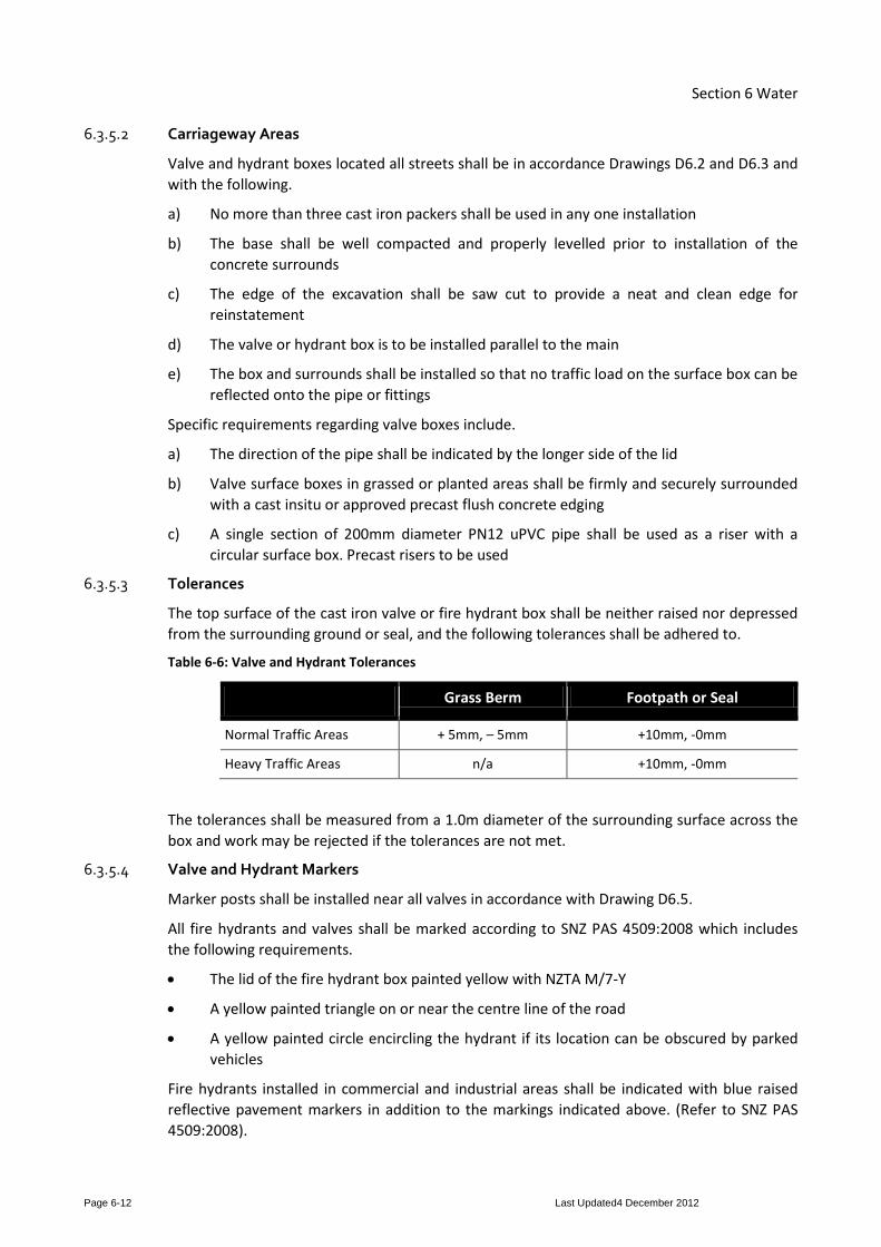
6.3.5.3 Tolerances
The top surface of the cast iron valve or fire hydrant box shall be neither raised nor depressed from the surrounding ground or seal, and the following tolerances shall be adhered to.
Table 6-6: Valve and Hydrant Tolerances
Grass Berm Footpath or Seal
Normal Traffic Areas + 5mm, – 5mm +10mm, -0mm
Heavy Traffic Areas n/a +10mm, -0mm
The tolerances shall be measured from a 1.0m diameter of the surrounding surface across the box and work may be rejected if the tolerances are not met.
6.3.5.4 Valve and Hydrant Markers
Marker posts shall be installed near all valves in accordance with Drawing D6.5.
All fire hydrants and valves shall be marked according to SNZ PAS 4509:2008 which includes the following requirements.
• The lid of the fire hydrant box painted yellow with NZTA M/7-Y
• A yellow painted triangle on or near the centre line of the road
• A yellow painted circle encircling the hydrant if its location can be obscured by parked vehicles
Fire hydrants installed in commercial and industrial areas shall be indicated with blue raised reflective pavement markers in addition to the markings indicated above. (Refer to SNZ PAS 4509:2008).

Section 6 Water
Page 6-13 Last Updated4 December 2012
6.3.6 Connections Refer drawings D6.7, D6.8, D6.9 and D6.10.
All connections shall be sealed by removable caps until such time as they are required.
All connections and disconnections to or from Council pipes and all works outside the property boundary shall be undertaken by Council.
The physical connection to the existing water reticulation can only be carried out once the pressure and bacteriological test results have been submitted to, and approved by Council.
Connections shall be made under pressure wherever possible.
Domestic supplies will not be metered, however a manifold box. Backflow protection is required as per NZ Building Code – Clause G12 “Water Supplies”.
Care shall be taken during installation of the connection to ensure that no foreign matter enters the pipes or meter. All meters shall be checked after installation to ensure that the meter is recording the flow passing through it.
6.3.6.1 Tapping Bands, Ferrules and Service Pipes
Service connections to principal mains shall be by means of a tapping band and a ferrule. Service connections to rider mains shall be by means of a tee-joint or Tapping Saddle. Ferrules are to be left fully opened and gate valves fully closed.
All service pipes shall be laid at right angles to the street (refer to Drawing D6.7).
Tapping bands and ferrules on the water main shall be fitted when the mains are first laid.
6.3.7 Embedment, Backfilling and Reinstatement Pipes and fittings shall be surrounded with a suitable bedding material and backfilled using an approved hardfill placed immediately above the pipe embedment and compacted in layers not exceeding 200mm in loose depth in accordance with Drawing D3.2.3 and NZS 2566.
The depth of basecourse and type of the finishing seal coat shall conform to the standard of the existing road construction.
Compaction test results (or substituted scala penetrometer tests) shall be submitted to Council for approval.
6.3.7.1 Detector Tape
For all steel pipelines, backfill shall be placed to 100mm below final ground level and metallic ‘detector’ tape coloured blue, stipulating ‘Danger – Water Main Below’ (or similar) shall be laid.
6.3.7.2 Tracer Wire
Tracer wire, in the form of a continuous 4mm2 multi strand (minimum four) polythene sleeved copper cable, shall be installed with all non-metallic pipes to allow detection. The wire shall be strapped to the pipe wall by means of a minimum of two complete wraps of heavy duty adhesive tape, at a maximum of 3.0m intervals. The wire shall have some slack to allow for bends in laying and for future installation of tapping saddles.
The tracer wire shall run continuously between valves and hydrants. At each valve or hydrant the wire shall be ducted to surface level through a length of polyethylene pipe ending immediately below the lid. The tracer wire shall be long enough to extend 600mm minimum above ground level when uncoiled. The excess length shall be neatly coiled in the valve or hydrant box.

Section 6 Water
Page 6-14 Last Updated4 December 2012
The tracer wire shall be tested for continuity between surface boxes using an electronically generated tone and detector probe or alternative approved method.
This procedure also applies when a pipe is installed by a directional drilling technique.
6.3.8 Pressure Testing Before joints are covered, but after anchor blocks are completed, each section of the reticulation, together with all specials and fittings connected thereto shall be tested in the presence of Council prior to the pipe being connected to the ‘live’ network.
The reticulation shall withstand a pressure of 1200 kPa measured at the lowest point of the section under test. The required pressure shall be maintained for a period of 15 minutes. Before arranging connection to the existing reticulation, Council may require a similar test after completion of backfilling and any other adjoining works which may affect the water reticulation.
6.3.9 Disinfection and Flushing 6.3.9.1 General Procedure
Generally, pipeline pressure testing and disinfection shall be witnessed by Council. At least one working days advance notice for each of, pressure testing and disinfecting a pipeline shall be provided to Council.
Persons (or supervisor) carrying out pressure testing and disinfection water mains shall hold the NZQA qualification “National Certificate in Water Reticulation”.
The process of commissioning a pipeline shall follow the general procedure outlined below.
• The pipeline is pressure tested, disinfected using dissolved HTH powder, thoroughly flushed and then left in the ‘in-service’ and pressurised state
In the second of these options, if further work on the pipeline is required as a result of a failed pressure test then the disinfection step shall be repeated (using dissolved HTH powder).
6.3.9.2 Disinfection
After backfilling and before being put into service, all pipes, valves, house connections and other fittings shall be disinfected at no cost to Council.
Disinfection chemicals should be applied to achieve a free chlorine concentration of 50mg/litre (the pH should not be higher than pH 9 – concrete lined pipes can cause the pH to be raised to the point where chlorine becomes ineffective). It is recommended that this is done via a water tanker of known volume.
The main shall be left full of chlorinated water for a minimum time of 24 hours and at the end of the disinfection period, the free chlorine concentration shall be not less than 10mg/litre. If at the end of the disinfection period the free chlorine concentration is less than 10mg/litre then the pipeline shall be thoroughly flushed and the disinfection process repeated.
If the disinfection process is being applied to a pipeline with customer connections each service pipeline shall closed at the toby prior to the disinfectant being administered.

Section 6 Water
Page 6-15 Last Updated4 December 2012
Table 6-7: Disinfection Dosing Requirements
Quantity (Grams) of HTH Powder Required to Chlorinate Each 100 metres of Ridermain / Watermain
Diameter of Water Main in mm (DN)
HTH* for dose of 50mg/L (grams)
Volume (m3)
50 (63mm OD) 15 0.2
150 135 1.8
250 375 4.9
300 540 7.0
* Calcium Hypochlorite (Ca(OCl)2) also known as HTH (High Test Hypochlorite) is a powder with typically 65% to 70% available chlorine by weight.
Disinfection of mains over and above 300mm will require a specific methodology to be approved by Council.
Warning: These chemicals are strong oxidants and can cause serious burns; they are explosive if allowed to come into contact with organic liquids such as petrol, diesel and oil. Using the chemicals should only be undertaken by personnel trained in this application of disinfecting water.
6.3.9.3 Removing the Disinfectant
Sometime after the minimum contact period for disinfection, the super chlorinated water is to be flushed from the pipeline. Flushing should continue for at least 10 minutes beyond the initial removal of the super chlorinated water. Projects involving pipelines of 250 NB and larger should be flushed until such time as the residual chlorine level matches that of the normal water supply in the area (i.e. upstream of the new pipe).
Individual customer connections shall be flushed by opening each toby valve installed on the pipeline. In the case of a pipeline repair where it is not practical to flush water at the toby, an outside hose tap should be used as the flushing point for each service connection.
If the super chlorinated water cannot be discharged to a sewer, it shall be neutralised before discharge to the environment.
6.3.9.4 Bacteriological Test
In commissioning new pipelines, Council shall be given 24 hours notice as to when sampling for bacteriological tests is to be carried out.
Water in the pipeline shall be sampled between 12 hours and 48 hours after post-chlorination flushing and the samples tested for the presence of E.Coli, Coliforms and Heterotrophic Plate Count by a Ministry of Health Approved laboratory with IANZ accreditation for this type of test. The number of samples shall be at least one for projects involving less than 100m of pipe, two for projects up to 200m length, etc.
A satisfactory result is zero E.Coli, Coliforms and Heterotrophic Plate Count per 100ml.
If E.Coli is detected the pipeline shall be swabbed, flushed, disinfected, flushed again and then the bacteriological tests repeated. The process shall be repeated until such time a clear test is recorded.
Note: There are high risks of test failure due to sample contamination so it is recommended that the testing laboratory is also involved in collecting the sample.

Section 6 Water
Page 6-16 Last Updated4 December 2012
6.3.10 Water Mains to be Kept Charged After any water main has been laid, tested and disinfected, it shall be kept continually charged with water, and under pressure. If the permanent connection to the existing reticulation is delayed, a temporary small diameter connection shall be made from the existing reticulation. The pressure must be maintained while other underground services are being laid in the vicinity of the new main.
6.3.11 Abandoned Water mains In the event that a water main is decommissioned, all removable valves, hydrants, fittings and surface boxes shall be recovered. The items shall be recycled, either by delivery to Council for reuse or by delivery to a scrap metal merchant.
Council shall be provided with an opportunity to inspect the removed items and direct which recycling option is to be taken.

Section 6 Water
Page 6-17 Last Updated4 December 2012
Appendix A Forms and Checklists
Table 6-8: Forms and Checklists
Number Title F6.1 Quality Assurance Design Certificate F6.2 Pipe Laying Checklist F6.3 Final Inspection Checklist

Quality Assurance Design Certificates
F6.1 Infrastructure Technical Specifications
Version : October 2012 Page 1 of 1
WATER/WASTEWATER/STORMWATER – QUALITY ASSURANCE DESIGN CERTIFICATE
Site Address/Project Name
Consent Number if known
Name of Designer
Designers relevant qualifications
I hereby confirm that the design of the water reticulation / wastewater provision / Stormwater provision for the above site has been designed in accordance with the following standard _________________________________
Engineering Exception Decisions
The following aspects of the design do not meet the requirements of the above standard. (Where standards are not met, please detail the alternative standard achieved).
Accepted Y N
Signed: Date:

Pipe Laying Checklist F6.2 Infrastructure Technical
Specifications
Version : October 2012 Page 1 of 1 For further information about this form, email [email protected]
WATER RETICULATION PIPE LAYING CHECKLIST
Location:
To
To
To
To
To
Name of qualified water service person:
From
From
From
From
From
Pipe Laying Checks
• Pipe size, quality, approved materials checked.
• Set out checked (control points)
• Foundation support • penetrometer results available • if under cutting required, note
chainage and CBR results.
• Alignment and cover.
• Bedding type and backfill material (CBR results available for road crossings and driveways).
• All service connections in place.
• Connections and Toby Box correctly located horizontally and vertically.
• Hydrants and valves positioned correctly.
• Thrust blocks installed.
• No debris in pipelines.
• As-built measurements taken.
• Pressure test witnessed and passed by Council representative.
• Bacto sample taken and passed by Council representative PRIOR to connection to the live Council main.
• Connection to live main by Council (unless specifically approved).
________________________________________ ________________________________________
Developer Date

Water Reticulation
Final Inspection Checklist
F6.3 Infrastructure Technical Specifications
Version : October 2012 Page 1 of 1 For further information about this form, email [email protected]
FINAL INSPECTION FOR WATER RETICULATION
Location:
Plan No:
Pre-Meeting Tasks
Developer to verify prior to meeting: Developer Check WWS Rep Check
1. All lines flushed out
2. All backfilling complete and tidied up
3. Checklists 6.1 and 6.2 completed
4. Pressure test completed and witnessed
5. Bacto test completed and passed
6. Final as-built plans attached for a inspection arranged with Council
7. Connected to existing supply by Council
Site Meeting
1. Valves and hydrants correctly marked
2. Toby boxes installed correctly
3. All valves checked on/off
All works satisfactory
Remedial work required
________________________________________ ________________________________________ Developer Council
________________________ ________________ ________________________________________ Date Date

Section 6 Water
Page 6-18 Last Updated4 December 2012
Appendix B Drawings
Table 6-9: Drawing Register
Drawing No. Title
D6.1 Typical Network Layout
D6.2 Sluice Valve
D6.3 Fire Hydrant
D6.4 Valve Indicator and Post Details
D6.5 Ridermain in a Cul-de-Sac
D6.6 20mm Metered and Unmetered Service Connections
D6.7 20mm Metered and Unmetered Multi-Service Connections
D6.8 50mm Meter Connection
D6.9 100mm and 150mm Meter Connection

Lot 1
Lot 2
Lot 6
Lot 7
Lot 8
Lot 910
LotLot 11
Lot 12
Lot 13
Lot 14
Lot 18
Requirements
see Standard
For location
Ridermain
Lot 19
Location of valves
Ridermain
See D5.6
Main
Layout
Alternative
Lot 15
District Council
required by the relevant
in a different position as
This valve may be relocated
TYPICAL NETWORK LAYOUT D6.1
City Council
INFRASTRUCTURE TECHNICAL SPECIFICATION Version: NOVEMBER 2012
Valve Indicator D6.4
Service Connection D6.6
Hydrant installation D6.3
Valve Indicator D6.4
Valve Indicator D6.4

Standard C.I. valve box
surrounds
Pre-cast concrete
Sand backfill Original excavation
75
Tolerance +10mm -0mm
Sawcut existing seal
(- min 1, max. 3)
packers
Cast iron valve
(See Note 1)
’Hotmix’ asphalt well compacted
one piece 150mm pipe
Riser fabricated from
100 100230
100
100
160
Direction of Main
of Main
Direction
230160
300 255
D6.2
City Council
INFRASTRUCTURE TECHNICAL SPECIFICATION Version: NOVEMBER 2012
SLUICE VALVE
145
150
(with concrete surroundings for grass berms)
RECTANGULAR VALVE BOX AND COVER
b) the finished surface shall match the surrounding
a) the TNZ backfill can be replaced with pitsand
1. In Berm Areas
NOTES:
D3.2.3
Backfill as per

Sawcut existing seal
hydrant box
Standard C.I.
Hydrant tee
75
Tolerance +10mm - 0mm
max. 3)
packers (- min 1,
Cast iron valve
(See Note 1)
’Hotmix’ asphalt well compacted
50 - 2
00
base (100mm)
Heavy duty concrete
(100mm thick)
surrounds
Pre-cast concrete
(with concrete surroundings for grass berms)
HYDRANT BOX AND COVER
110 110430
110
110
280
Direction of Main
of Main
Direction
430280
pipe
PVC surround
Concrete or
is a 375mm dia.
An alternative
Sand backfill
D6.3
b) the finished surface shall match the surrounding
a) the TNZ backfill can be replaced with pitsand
1. In Berm Areas
NOTES:
145
150
City Council
INFRASTRUCTURE TECHNICAL SPECIFICATION Version: NOVEMBER 2012
FIRE HYDRANT
per D3.3.1
Backfill as
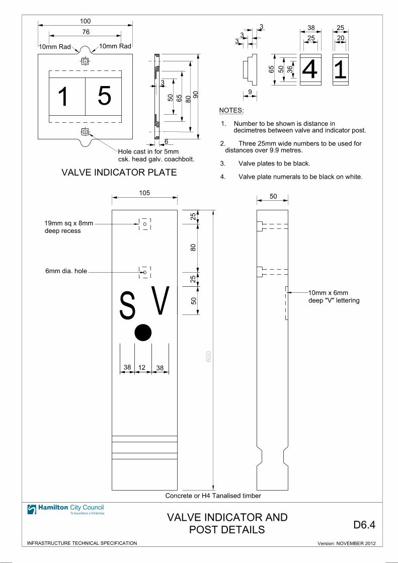
SV
6mm dia. hole
50
deep recess
19mm sq x 8mm
deep "V" lettering
10mm x 6mm
38 3812
25
80
25
Concrete or H4 Tanalised timber
POST DETAILS
VALVE INDICATOR AND
Valve plate numerals to be black on white.4.
Valve plates to be black.3.
distances over 9.9 metres.
Three 25mm wide numbers to be used for 2.
decimetres between valve and indicator post.
Number to be shown is distance in 1.
NOTES:
1 5
VALVE INDICATOR PLATE
100
10mm Rad
76
10mm Rad
3
50
65
1
3
33
25
20
4
38
25
65
50
36
csk. head galv. coachbolt.
Hole cast in for 5mm
6
9
50
90
80
D6.4
City Council
INFRASTRUCTURE TECHNICAL SPECIFICATION
600
105
Version: NOVEMBER 2012

Ridermain
450 Min.
1000 Max.
Concrete thrust block
installation see D6.3
For details of hydrant
connections see D5.7
Metered / Unmetered
Concrete Surround150mm pipe
from one piece
Riser fabricated
City Council
INFRASTRUCTURE TECHNICAL SPECIFICATION
D6.5
by suitably sized tapping band
Tapped gibault may be replaced
NOTE:
300 M
ax.
500
mm Min. cover
RIDERMAIN IN A CUL-DE-SAC
Version: NOVEMBER 2012

Adaptor
25mm MDPE25mm MDPE
SERVICE CONNECTIONS
20mm METERED AND UNMETERED
OR
compacted under pipe
Backfill to be well
(may be horizontal to maintain cover)
25mm on 63mm Tapping Saddle
fitting or tapping saddle
Ridermain ’tee’ joint
to Toby Box
Angle vertically
20mm Ferrule
band and ferrule
Principal main tapping
D6.6
Point of supply
Boundary
contaminants
to prevent ingress of
Male Adaptor, sealed
Isolating valve
25mm MDPE Pipe
HCC Supply
Class ’C’ Meter
Lid
Flow
User line
25mm MDPE Pipe
Boundary
PLAN
Manifold Box
300mm 300mm Tail200mm Wide
250mm LG x
50
mm M
IN
300300
City Council
INFRASTRUCTURE TECHNICAL SPECIFICATION
tapping saddle prior to the installation of other fittings.
When a connection is made to an existing watermain, a gunmetal self-tapping ferrule shall be installed directly on the 1.
NOTE:
coupling.
to surround via stainless steel flexible
’WATER’ moulded into top) and lid secured
mounting lugs with blue moulded lid (with
Moulded manifold box with base and
Hig
h
350
mm
thread
25mm x ¾" BSP
Male threaded adaptor
BSP ¾" thread both ends.
with dual check valve, female
RMC 20mm manifold assembly
than 600mm
Radius not less
Version: NOVEMBER 2012

230
63mm MDPE fittings
and surround
Standard C.I. Valve Box
63mm MDPE
Tapping band onto Watermain
Tapped gibault or
MDPE for 25mm connections
connections and 32mm
25mm MDPE for 20mm
suit number of connections
PE Manifold size varied to
300
Boundary (point of supply)300
contaminants
to prevent ingress of
Male Adaptor, sealed
on LHS
connection
Unit 1 / Lot 1
for all 20mm connections
with dual check valve,
RMC manifold assembly
Approved tapping band
NTS
MANIFOLD ASSEMBLY FOR MULTIPLE WATER CONNECTIONS
D6.7
City Council
INFRASTRUCTURE TECHNICAL SPECIFICATION
SERVICE CONNECTIONS
20mm METERED & UNMETERED
connections. Meters installed on all connections serving commercial / industrial zoned lots.
RMC manifolds with pressure caps to be installed on all 20mm diameter domestic 3.
or tapped gibault. Tee to be placed horizontally to maintain standard cover.
Connections from ridermains to be made using 63 x 63 MDPE tee in place of a tapping band 2.
In-line or one-sided arrangements permitted to suit site conditions.1.
NOTES:
Version: NOVEMBER 2012

Meter box - See Note 3
80mm dia or larger)(or cut-in tee onTapping Band
Valve
Watermain
of connectionSee Detail A for plan
Valve
Boundary
To customer
Point of supply
Lid
See Note 1 See Note 1
City Council
INFRASTRUCTURE TECHNICAL SPECIFICATION
D6.8
300mm
230
50mm METER CONNECTION
Version: NIOVEMBER 2012
DETAIL A
Lot, to be owned and maintained by the property owner.
the NZ Building Code G12 shall be installed within the
Any backflow requirements necessary to comply with5.
cut-in tee, tapped gibault or other as directed.
In new installations tapping band may be replaced by4.
Meter box sized to contain all fittings.3.
components of dissimilar metals.
Isolation washers and gaskets to be used between2.
times pipe diameter.
manufacturer’s specification or otherwise minimum 5
Upstream and downstream spacing in accordance with1.
NOTES:

Version: JULY 2012
GIBAULT JOINT
FLANGED GIBAULT JOINT
PVC PIPE
BO
UN
DA
RY
POINT OF SUPPLY
SLUICE VALVE PVC PIPE
METER
AQUAMASTER
SOCKET JOINT
FLANGED DISPLAY
REMOTE
PVC PIPE
LID
SEE NOTE 5
METER BOX -
(100mm CONNECTION SHOWN)
SECTIONAL ELEVATION
(100mm CONNECTION SHOWN)
PLAN VIEW
D6.9
300mm 300mm
100 & 150mm METER CONNECTIONS
City Council
INFRASTRUCTURE TECHNICAL SPECIFICATION
property owner.
to be owned and maintained by the
G12 shall be installed within the Lot,
to comply with the NZ Building Code
Any backflow requirements necessary6.
Meter box sized to contain all fittings.5.
stainless bracket.
Display to be remote mounted with4.
chamber wall (2.5mm polythene).
around pipe where it passes through
Protective membrane to be wrapped3.
dissimilar metals.
used between components of
Isolation washers and gaskets to be2.
of 5 times pipe diameter.
specification or otherwise minimum
in accordance with manufacturer’s
Upstream and downstream spacing1.
NOTES: