Embed Size (px)
Citation preview
6.0 JET ENGINE WAKE AND NOISE DATA
6.1 Jet Engine Exhaust Velocities and Temperatures
6.2 Airport and Community Noise
D6-58326-1 DECEMBER 2002 139
6.0 JET ENGINE WAKE AND NOISE DATA
6.1 Jet Engine Exhaust Velocities and Temperatures
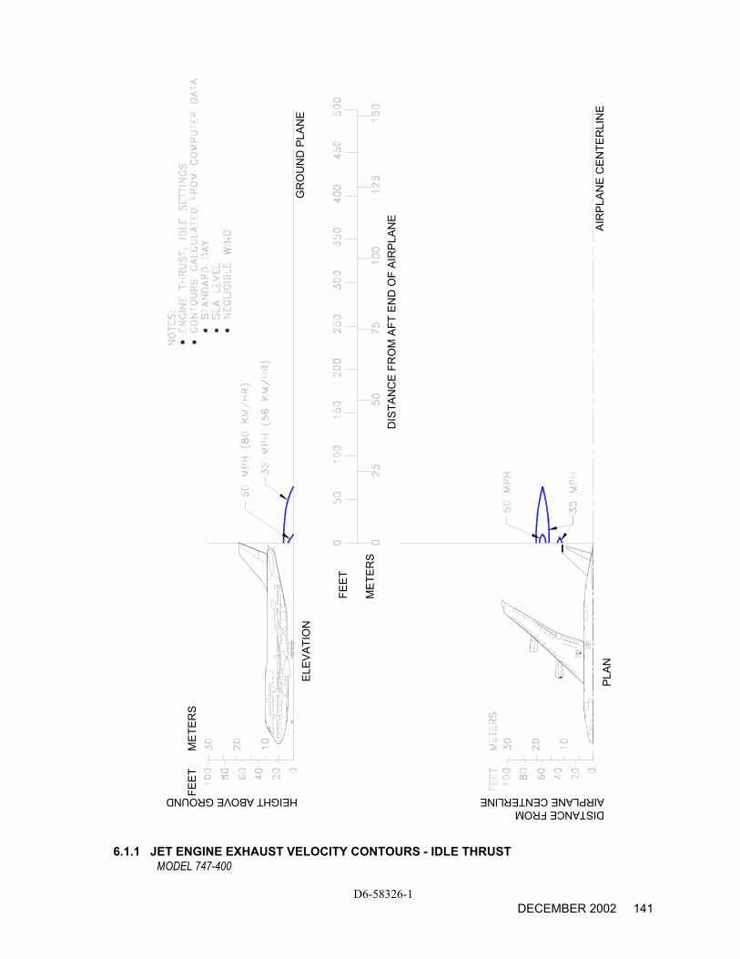
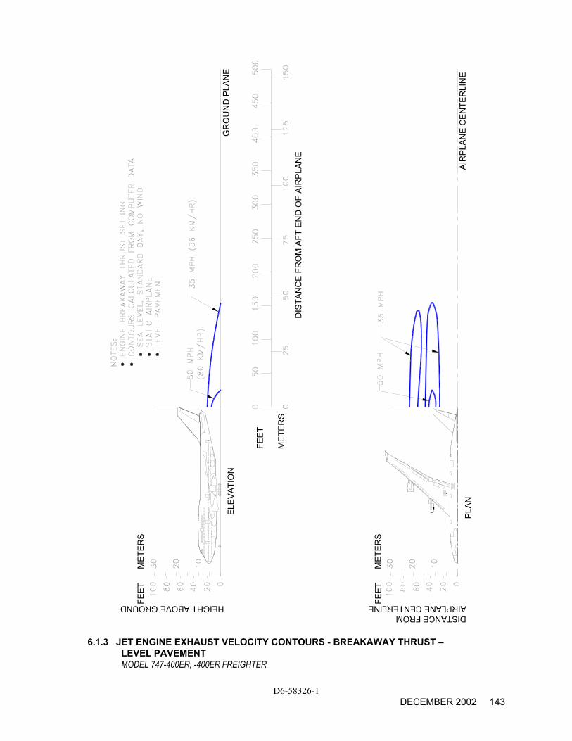
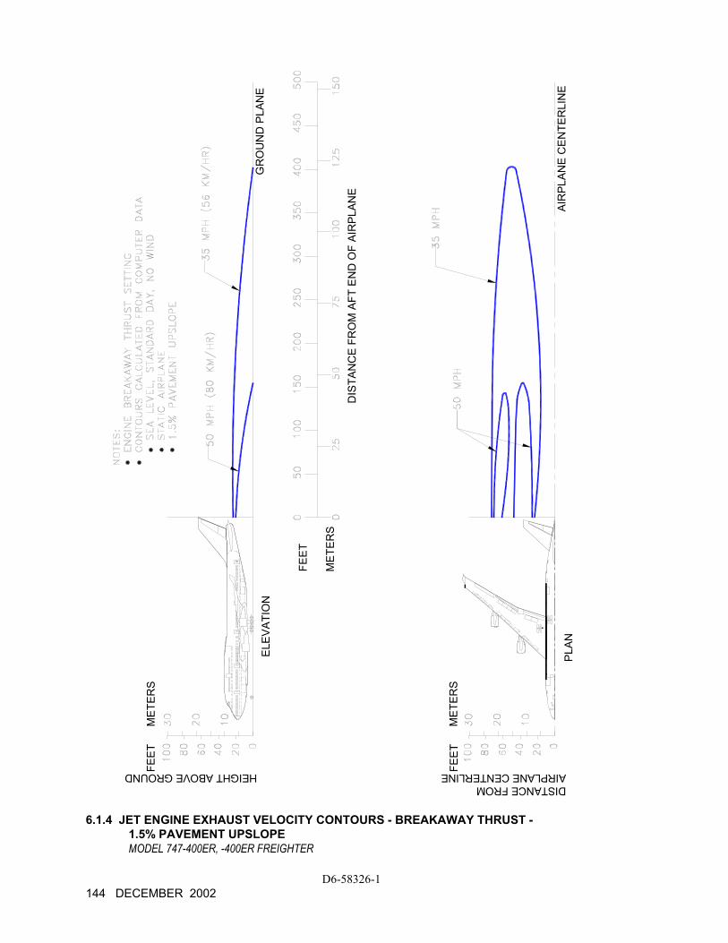
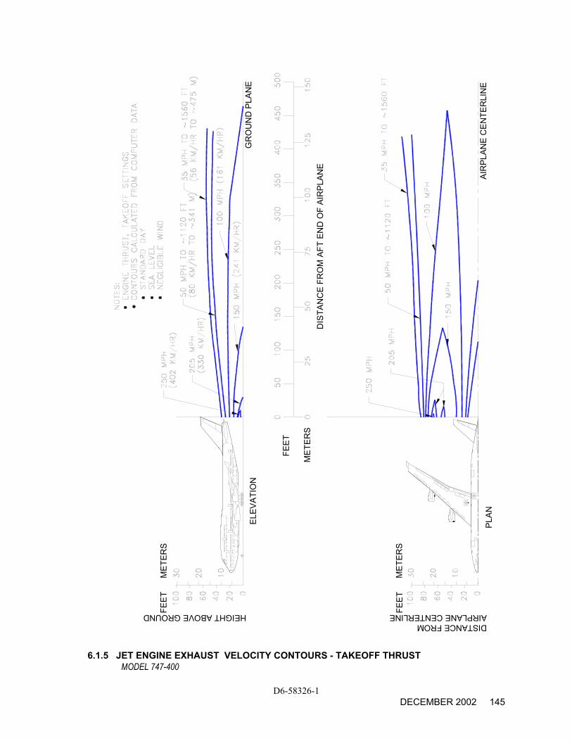
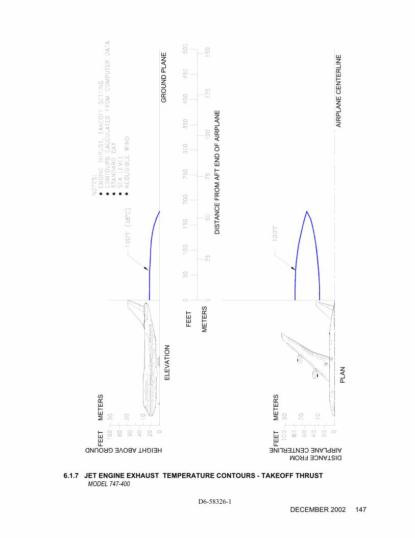
This section shows exhaust velocity and temperature contours aft of the 747-400 airplane. The contours were calculated from a standard computer analysis using three-dimensional viscous flow equations with mixing of primary, fan, and free-stream flow. The presence of the ground plane is included in the calculations as well as engine tilt and toe-in. Mixing of flows from the engines is also calculated. The analysis does not include thermal buoyancy effects which tend to elevate the jet wake above the ground plane. The buoyancy effects are considered to be small relative to the exhaust velocity and therefore are not included.
The graphs show jet wake velocity and temperature contours for a representative engine . The results are valid for sea level, static, standard day conditions. The effect of wind on jet wakes was not included. There is evidence to show that a downwind or an upwind component does not simply add or subtract from the jet wake velocity, but rather carries the whole envelope in the direction of the wind. Crosswinds may carry the jet wake contour far to the side at large distances behind the airplane.
D6-58326-1 140 DECEMBER 2002
AIRPLANE CENTERLINE
ELEV
ATIO
N
PLAN
FEET
MET
ERS
DIS
TAN
CE
FRO
M A
FT E
ND
OF
AIR
PLAN
E
AIR
PLAN
E C
ENTE
RLI
NE
GR
OU
ND
PLA
NE
MET
ERS
FEET
HEIGHT ABOVE GROUNDDISTANCE FROM
6.1.1 JET ENGINE EXHAUST VELOCITY CONTOURS - IDLE THRUST MODEL 747-400
D6-58326-1 DECEMBER 2002 141
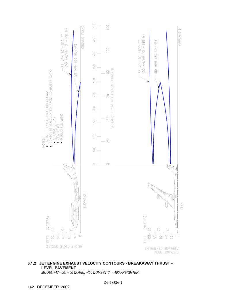
6.1.2 JET ENGINE EXHAUST VELOCITY CONTOURS - BREAKAWAY THRUST – LEVEL PAVEMENT MODEL 747-400, -400 COMBI, -400 DOMESTIC, - 400 FREIGHTER
D6-58326-1 142 DECEMBER 2002
DISTANCE FROM
ELEV
ATIO
N
PLAN
FEET
MET
ERS
DIS
TAN
CE
FRO
M A
FT E
ND
OF
AIR
PLAN
E
AIR
PLAN
E C
ENTE
RLI
NE
GR
OU
ND
PLA
NE
MET
ERS
FEET
MET
ERS
FEET
HEIGHT ABOVE GROUND AIRPLANE CENTERLINE
6.1.3 JET ENGINE EXHAUST VELOCITY CONTOURS - BREAKAWAY THRUST – LEVEL PAVEMENT MODEL 747-400ER, -400ER FREIGHTER
D6-58326-1 DECEMBER 2002 143
DISTANCE FROM
ELEV
ATIO
N
PLAN
FEET
MET
ERS
DIS
TAN
CE
FRO
M A
FT E
ND
OF
AIR
PLAN
E
AIR
PLAN
E C
ENTE
RLI
NE
GR
OU
ND
PLA
NE
MET
ERS
FEET
MET
ERS
FEET
HEIGHT ABOVE GROUND AIRPLANE CENTERLINE
6.1.4 JET ENGINE EXHAUST VELOCITY CONTOURS - BREAKAWAY THRUST - 1.5% PAVEMENT UPSLOPE MODEL 747-400ER, -400ER FREIGHTER
D6-58326-1 144 DECEMBER 2002
AIRPLANE CENTERLINEDISTANCE FROM
ELEV
ATIO
N
PLAN
FEET
MET
ERS
DIS
TAN
CE
FRO
M A
FT E
ND
OF
AIR
PLAN
E
AIR
PLAN
E C
ENTE
RLI
NE
GR
OU
ND
PLA
NE
MET
ERS
FEET
MET
ERS
FEET
HEIGHT ABOVE GROUND
6.1.5 JET ENGINE EXHAUST VELOCITY CONTOURS - TAKEOFF THRUST
MODEL 747-400
D6-58326-1 DECEMBER 2002 145
DISTANCE FROM
ELEV
ATIO
N
PLAN
FEET
MET
ERS
DIS
TAN
CE
FRO
M A
FT E
ND
OF
AIR
PLAN
E
AIR
PLAN
E C
ENTE
RLI
NE
GR
OU
ND
PLA
NE
MET
ERS
FEET
MET
ERS
FEET
HEIGHT ABOVE GROUND AIRPLANE CENTERLINE
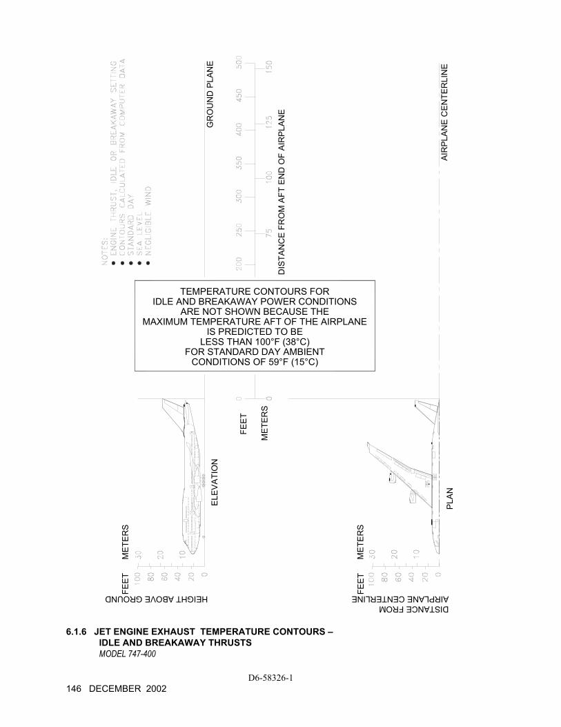
TEMPERATURE CONTOURS FORIDLE AND BREAKAWAY POWER CONDITIONS
ARE NOT SHOWN BECAUSE THEMAXIMUM TEMPERATURE AFT OF THE AIRPLANE
IS PREDICTED TO BELESS THAN 100°F (38°C)
FOR STANDARD DAY AMBIENTCONDITIONS OF 59°F (15°C)
6.1.6 JET ENGINE EXHAUST TEMPERATURE CONTOURS – IDLE AND BREAKAWAY THRUSTS MODEL 747-400
D6-58326-1 146 DECEMBER 2002
DISTANCE FROM
ELEV
ATIO
N
PLAN
FEET
MET
ERS
DIS
TAN
CE
FRO
M A
FT E
ND
OF
AIR
PLAN
E
AIR
PLAN
E C
ENTE
RLI
NE
GR
OU
ND
PLA
NE
MET
ERS
FEET
MET
ERS
FEET
HEIGHT ABOVE GROUND AIRPLANE CENTERLINE
6.1.7 JET ENGINE EXHAUST TEMPERATURE CONTOURS - TAKEOFF THRUST MODEL 747-400
D6-58326-1 DECEMBER 2002 147
6.2 Airport and Community Noise
Airport noise is of major concern to the airport and community planner. The airport is a major element in the community's transportation system and, as such, is vital to its growth. However, the airport must also be a good neighbor, and this can be accomplished only with proper planning. Since aircraft noise extends beyond the boundaries of the airport, it is vital to consider the impact on surrounding communities. Many means have been devised to provide the planner with a tool to estimate the impact of airport operations. Too often they oversimplify noise to the point where the results become erroneous. Noise is not a simple subject; therefore, there are no simple answers.
The cumulative noise contour is an effective tool. However, care must be exercised to ensure that the contours, used correctly, estimate the noise resulting from aircraft operations conducted at an airport.
The size and shape of the single-event contours, which are inputs into the cumulative noise contours, are dependent upon numerous factors. They include the following:
1. Operational Factors
(a) Aircraft Weight-Aircraft weight is dependent on distance to be traveled, en route winds, payload, and anticipated aircraft delay upon reaching the destination.
(b) Engine Power Settings-The rates of ascent and descent and the noise levels emitted at the source are influenced by the power setting used.
(c) Airport Altitude-Higher airport altitude will affect engine performance and thus can influence noise.
2. Atmospheric Conditions-Sound Propagation
(a) Wind-With stronger headwinds, the aircraft can take off and climb more rapidly relative to the ground. Also, winds can influence the distribution of noise in surrounding communities.
(b) Temperature and Relative Humidity-The absorption of noise in the atmosphere along the transmission path between the aircraft and the ground observer varies with both temperature and relative humidity.
D6-58326-1 148 DECEMBER 2002
3. Surface Condition-Shielding, Extra Ground Attenuation (EGA)
(a) Terrain-If the ground slopes down after takeoff or up before landing, noise will be reduced since the aircraft will be at a higher altitude above ground. Additionally, hills, shrubs, trees, and large buildings can act as sound buffers.
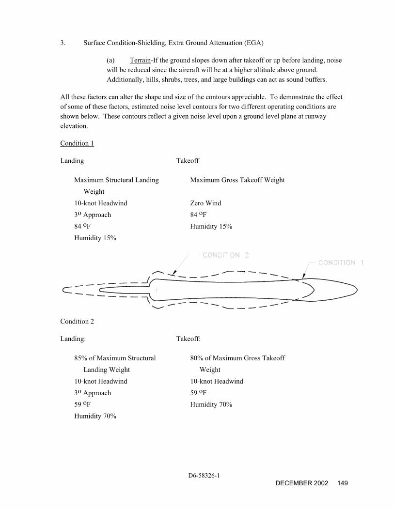
All these factors can alter the shape and size of the contours appreciable. To demonstrate the effect of some of these factors, estimated noise level contours for two different operating conditions are shown below. These contours reflect a given noise level upon a ground level plane at runway elevation.
Condition 1
Landing Takeoff
Maximum Structural Landing Weight
Maximum Gross Takeoff Weight
10-knot Headwind Zero Wind 3o Approach 84 oF 84 oF Humidity 15% Humidity 15%
Condition 2
Landing: Takeoff:
85% of Maximum Structural Landing Weight
80% of Maximum Gross Takeoff Weight
10-knot Headwind 10-knot Headwind 3o Approach 59 oF 59 oF Humidity 70% Humidity 70%
D6-58326-1 DECEMBER 2002 149
As indicated from these data, the contour size varies substantially with operating and atmospheric conditions. Most aircraft operations are, of course, conducted at less than maximum gross weights because average flight distances are much shorter than maximum aircraft range capability and average load factors are less than 100%. Therefore, in developing cumulative contours for planning purposes, it is recommended that the airlines serving a particular city be contacted to provide operational information.
In addition, there are no universally accepted methods for developing aircraft noise contours or for relating the acceptability of specific zones to specific land uses. It is therefore expected that noise contour data for particular aircraft and the impact assessment methodology will be changing. To ensure that the best currently available information of this type is used in any planning study, it is recommended that it be obtained directly from the Office of Environmental Quality in the Federal Aviation Administration in Washington, D.C.
It should be noted that the contours shown herein are only for illustrating the impact of operating and atmospheric conditions and do not represent the single-event contour of the family of aircraft described in this document. It is expected that the cumulative contours will be developed as required by planners using the data and methodology applicable to their specific study.
D6-58326-1 150 DECEMBER 2002