Embed Size (px)
Citation preview

BNL- 6 5 446 t CON F - 4 ctjt 6 $0 2 - -
Optimization of the Polyplanar Optical Display Electronics for a Monochrome B-52 Display
Leonard DeSanto , --_ Department of Advanced Technology, Brookhaven National Laboratory
P ‘ i, E,- cj * - 7 F t iz 1 kF E p Upton, NY 11973 d
ABSTRACT Q S T l R 3 Y p f fy&
The Polyplanar Optical Display (POD) is a unique display screen which can be used with any projection source. The prototype ten-inch display is two inches thick and has a matte black face which allows for high contrast images. The prototype being developed is a form, fit and functional replacement display for the B-52 aircraft which uses a monochrome ten-inch display.
In order to achieve a long lifetime, the new display uses a new 200 mW green solid-state laser (10,000 hr. life) at 532 nm as its light source. To produce real-time video, the laser light is being modulated by a Digital Light Processing @LPTM) chip manufactured by Texas Instruments (TI). In order to use the solid-state laser as the light source and also fit within the constraints of the B-52 display, the Digital Micromirror Device @MDTM) chip is operated remotely fiom the Texas Instruments circuit board. In order to achieve increased brightness a monochrome digitizing interface was investigated.
The operation of the DMDTM divorced from the light engine and the interfacing of the DMDTM board with the RS-170 video format specific to the B-52 aircraft will be discussed, including the increased brightness of the monochrome digitizing interface. A brief description of the electronics required to drive the new 200 mW laser is also presented.
Keywords: DMDTM, POD, Interface, Laser, Video
2. INTRODUCTION
The goal of the Polyplanar Optic Display team at Brookhaven National Laboratory (BNL)2 is to develop a long life replacement for the B-52 display’. This development is being funded by the Productivity Reliability Availability and Maintainability Office (PRAM) at Wright-Patterson Air Force Base (WPAFB) and will be done in two phases. The goal of Phase 1 was to deliver a breadboard prototype and Phase 2 delivered a flight-qualified display. To accomplish this we are using the latest in the state-of- the-art variety of technologies. The display screen itself will be a Polyplanar Optic Display, invented and developed by James T. Veligdan at BNL. The light source for the display is a very small highly efficient 200 mW diode pumped doubled YAG green laser, and the spatial light modulator is a DigitaI Micromirror Device @MDm)3, developed by Texas Instruments.
At the conclusion of Phase 1, a working prototype of the B-52 display was delivered to the PRAM office of Wright Patterson Air Force Base. Although the display in Phase 1 was instrumental in proving many different concepts, it would not interface with the B-52 aircraft. The Phase 2 display takes its power and video signal through the B-52 display connector.
\
19980529 045

3. PHASEONE
The major obstacle to be overcome in Phase 1 was to fit the DMD", its circuit board, and the n- View interface into a B-52 display chassis along with the laser light source, its power supply and support electronics. This was inherently difficult because the display chassis is 9 x 8 x 14 inches and the TI light engine is 7 x 12 x 10 inches, including its power supply. The TI light engine consists of a circuit board containing the DMD" chip, a 270W nickel halide arc lamp, a motorized color wheel, input and output optics, the kame to which it all mounts, and several cooling fans.
To fit into the Air Force display chassis, the entire light engine was disassembled and re- configured. The optics for illuminating the DMDW and the optics for imaging the output were completely re-engineered to meet our needs. The electronics had to be modified and the DMDTM was extended off of its circuit board. The power, video controls and interface connectors for the display were kept external to the display chassis.
4. PHASE TWO
Phase 2 presented our group with most of the same obstacles of the Phase 1 display, and added some new challenges for us to overcome. There were three major challenges of Phase 2. The first and most obvious challenge was to increase the brightness of the display. This was accomplished with the selection of a new, more powerfd laser, 8 bit digitizing of the video signal, and improvements in the construction methods of the POD itself. The second challenge was to increase the quality and uniformity of the POD screen. Along with the increased quality and uniformity of the screen came some sacrifices; a newly developed method for removing laser speckle from the display image caused a 40% loss in brightness. The third challenge was to interface the display with the B-52 aircraft. This was accomplished by using a laser power supply that would operate from the 400 cycle available at the display connector, along with a dc to dc converter, that used the aircraft28 Vdc bus, to supply all the dc voltages needed by the DMD" board and the interface board.
On Jan 17 1998, at the conclusion of Phase 2, a working form, fit, functional prototype B-52 display was delivered to the PRAM Ofice at Wright-Patterson Air Force Base in Dayton, Ohio.
5. LIGHT SOURCE (LASER)
As delivered from the manufacturer, the TI light engine uses a 270 W nickel halide short arc lamp. When the lamp and its power supply are removed from the light engine, a jumper must be added to 56 pins 5 and 6 to bypass the lamp's power supply interlock. Also, ajumper must be added to J9 pins 1 and 2 to bypass the thermal interlock.
In Phase 1 the arc lamp was replaced by a small, frequency doubled Nd:YAG laser operating at 1064 doubled to 532 nm wavelength, built by Coherent (Model DPY3 15M). The Nd:YAG laser is pumped by a diode laser which is temperature tuned to optimize the performance of the Nd:YAG crystal. This laser produced 100 mW, cw, at a wavelength of 532 nm in the green portion of the spectrum. It measures only 1 x 1.5 x 3.5 inches and has an output beam diameter of 0.012 inch. In addition, it has a small controller that measures 1 x 2.5 x 3 inches and a 28Vdc power supply that is 1 x 3 x 11 inches. The laser controller is capable of varying the laser output power from 35 mW to 100 mW. For our application we hard wired the laser to continually output maximum power.
In Phase 2 we wanted to use the most powerful laser available that would be able to fit into the confines of the display chassis. After an exhaustive search we narrowed the selection down to two lasers.

DISCLAIMER
This report was prepared as an account of work sponsored by an agency of the United States Government. Neither the United States Government nor any agency thereof, nor any of their employes, makes any warranty, express or implied, or assumes any legal liability or responsibility for the accuracy, completeness, or use- fulness of any information, apparatus, product, or process disclosed, or represents that its use would not infringe privately owned rights. Reference herein to any spe- cific commercial product, proms, or service by trade name, trademark, manufac- turer, or otherwise docs not necessarily constitute or imply its endorsement, m m - mendation, or favoring by the United States Government or any agency thereof. The views and opinions of authors expressed herein do not necessarily state or reflect those of the United States Government or any agency thereof.

The first laser that we tried to work into our design was manufactured by Laser Power Corporation. This laser first caught our attention because of its high power and small size. It is a frequency doubled Nd:YAG laser operating in the green portion of the spectrum with an output power of 2 ?4 W. The laser head with its heat sink was approximately 10 x 6 x 4 inches which was within our design dimensions. The heat sinking requirements of the laser head, while demanding, were still within the realm of our design.
Laser Power 's Laser Head. Laser Power's Laser Power Supply.
The biggest obstacle for us was the size and power consumption of the power supply and control unit, which measured 14 x 30 x 6 inches, and required 115 Vac. We immediately discussed the possibility of doing away with the ac portion of the power supply and using the 28 Vdc bus from the aircraft. The dc requirement for the laser power supply and controller is 18 Vdc but at a current of almost 20 amps. Even though this laser was high power and relatively small in size, it was just not small enough for our application at this time.
The second laser that we looked at was manufactured by a small company called CrystaLaser. This laser is also a frequency doubled Nd:YAG laser operating in the green portion of the spectrum with a rated output power of 200 mW. The laser head measures 1.25 x 2 x 6.5 inches, which fit into our design even better than the Laser Power laser head because of the relaxed heat sinking requirements.
CrystaLaser 's 200 m W Laser Head and Power Supply/Controller
i
The most appealing factor in this laser was the size and power consumption of the power supply and controller. The power supply and controller measures only 2 x 4 x 6 inches, and draws only 9W of electrical energy. Originally the laser came with the choice of a 1 15 Vac / 60 cycle or a 220 Vac / 50 cycle power supply. Given the choice of 28 Vdc or 1 15 Vac / 400 cycle (the two power sources available in the B-52), the manufacturer was willing to design and fabricate the laser with a supply that ran off the 1 15 Vac / 400 cycle bus. The laser specifications of the CrystaLaser model GCL-200-L are listed below.
SPECIFICATION TABLE
Wavelength CW output power Beam divergence Beam diameter (l/e2) Stability (rms, over 2 hours) Polarization ratio Power consumption Dimension of laser head Dimension of power supply
532 nm 200 mW 2mrad <0.4 mm 3% >loo : 1 9 w 1.25 x 2 x 6.5 inches 2 x 4 x 6 inches
6. COLORWHEEL
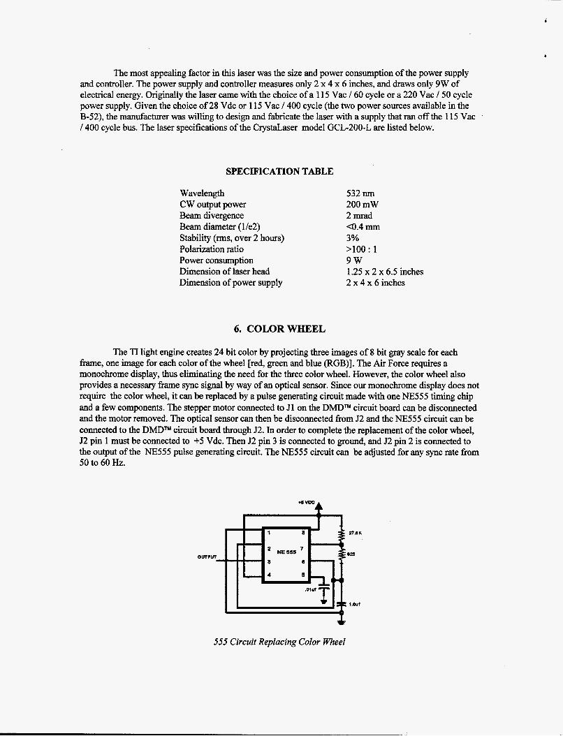
The TI light engine creates 24 bit color by projecting three images of 8 bit gray scale for each frame, one image for each color of the wheel [red, green and blue (RGB)]. The Air Force requires a monochrome display, thus eliminating the need for the three color wheel. However, the color wheel also provides a necessary frame sync signal by way of an optical sensor. Since our monochrome display does not require the color wheel, it can be replaced by a pulse generating circuit made with one NE555 timing chip and a few components. The stepper motor connected to 51 on the Dh4DTM circuit board can be disconnected and the motor removed. The optical sensor can then be disconnected from 52 and the NE555 circuit can be connected to the DMDTM circuit board through 52. In order to complete the replacement of the color wheel, 52 pin 1 must be connected to +5 Vdc. Then 52 pin 3 is connected to ground, and 52 pin 2 is connected to the output of the NE555 pulse generating circuit. The NE555 circuit can be adjusted for any sync rate from 50 to 60 Hz.
n . 6 K . 628 OUTPUT
- 4 8 cn
::.).out
555 Circuit Replacing Color Wheel

7. OPTICS
As supplied by TI, the input and output optics are completely inadequate for our application. The input optics must expand the 0.012 inch diameter laser beam to illuminate the DMDTM with a spot size of 0.75 inch diameter. The angle of the illuminating light must be 18.6 degrees h m the normal in the vertical and also 18.6 degrees fiom the normal in the horizontal. This comes out to 26.6 degrees coming in on a diagonal. In Phase 1 the laser was in line with this beam expander.
Phase I Side View of Optical Path
In Phase 2 this arrangement was not possible due to the length of the laser and the speckle reduction technique used. In order to couple the laser to the beam expander it would be necessary to use two mirrors or a single fiber. We opted for a single fiber for reasons that will be discussed in a later paper.
Side view of Displq Showing Relationship of Laser with Respect to Projector
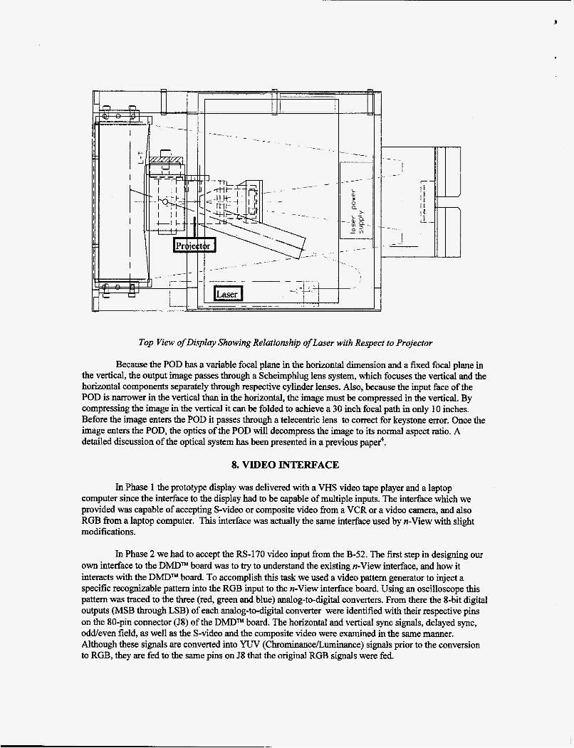
Top View of Display Showing Relationship of Laser with Respect to Projector
Because the POD has a variable focal plane in the horizontal dimension and a fixed focal plane in the vertical, the output image passes through a Scheimphlug lens system, which focuses the vertical and the horizontal components separately through respective cylinder lenses. Also, because the input face of the POD is narrower in the vertical than in the horizontal, the image must be compressed in the vertical. By compressing the image in the vertical it can be folded to achieve a 30 inch focal path in only 10 inches. Before the image enters the POD it passes through a telecentric lens to correct for keystone error. Once the image enters the POD, the optics of the POD will decompress the image to its normal aspect ratio. A detailed discussion of the optical system has been presented in a previous paper4.
8. VIDEO INTERFACE
In Phase 1 the prototype display was delivered with a VHS video tape player and a laptop computer since the interface to the display had to be capable of multiple inputs. The interface which we provided was capable of accepting S-video or composite video from a VCR or a video camera, and also RGB from a laptop computer. This interface was actually the same interface used by n-View with slight modifications.
In Phase 2 we had to accept the RS-170 video input fiom the B-52. The first step in designing OUT own interface to the DMDm board was to try to understand the existing n-View interface, and how it interacts with the DMDTM board. To accomplish this task we used a video pattern generator to inject a specific recognizable pattern into the RGB input to the n-View interface board. Using an oscilloscope this pattern was traced to the three (red, green and blue) analog-to-digital converters. From there the %bit digital outputs (MSB through LSB) of each analog-to-digital converter were identified with their respective pins on the 80-pin connector (J8) of the DMDm board. The horizontal and vertical sync signals, delayed sync, oddeven field, as well as the S-video and the composite video were examined in the same manner. Although these signals are converted into YUV (ChrominanceLuminance) signals prior to the conversion to RGB, they are fed to the same pins on 58 that the original RGB signals were fed.

As shown in the figure below we start by taking the RS-170 video signal and removing the sync signals. The video signal first goes into a sync separator, (EL4581C), and at the same time into the dc restoration amplifier, (EL4089C). The sync signals (vertical, horizontal, and oddeven field) are sent to the DMDW board along with a delayed and widened horizontal sync. The combination of the ELA581C and the EL4089C clamps the back-porch of the video signal to the ground level. The EL2 157C acts as a clamping stage to limit the negative excursion to the ground level. The video, having the sync removed and the dc level restored is then connected to the input of the high speed 8 bit analog-to-digital converter circuit shown in the schematic below. We selected the TLC5540,8 bit high speed analog-to-digital converter, from Texas Instruments. This converter is ideal for video analog-to-digital conversion. It has a sample rate of 40 megasamples per second (MSPS) and an analog input bandwidth of 75 MHz.
After fabricating a prototype of this interface board, the same video signal was connected to the n- View interface and the prototype board. A custom cable was made so that the n-View interface would drive the DMDW board, and then line-by-line the n-View interface was divorced from the DMDTM board and replaced with the prototype board. All inputs to the DMD" board were being supplied by the prototype board, with the exception of two serial encoded signals that were still being supplied by the n-View board. Without any information about these two signals, it was not possible for the prototype board to stand alone as the interface to the DMDTM board. Because we were unable to obtain information concerning these signals from Texas Instruments, we were forced to abandon this interface and settle for a modified n-View interface as shown in the following two diagrams.

In the n-View interface the one chip fiont end SAA71 IOA, (Philips Semiconductor), is a digital multistandard color decoder with two integrated analog-to-digital converters, a clock generation circuit and brightness contrast saturation control. The block diagram shows that we supply an analog video signal to the input of the SAA7 1 1 OA chip and produce a 16-bit YUV digital video output. This YUV signal serves as the input for the next stage of the interface.
I SRA7 1 9 2 A c i r c u t
board I
OSITE V I D E O n Y
6-VIDEO I r Y
+vrcso c I
T.
6 4 1 D E O V n 'I
5--VXD€O C
uvt COUPQ+XTE V I D E O uv.
uv: W:
UVI
uco LJW w
KT %
- SRR7 1 10R
4 - "9 I-9 c l k
I IU
I ' KUTr -6
m L u D DMD
c i r c u 1 t board
c
I I I

The Digital Color Space Converter (DCSC) SAA7192A, also from Philips Semiconductor, is a digital matrix which is used to transform the 16-bit digital signals[Y(Luminance) and UV(Chrominance)] into the RGB format that is required by the DMDTM circuit board. We see that the SAA7 192A has as its input the YUV output of the SAA7110A. We are only interested in a monochrome image so we do not need to convert the image to RGB and therefore we do not need to use the UV(Chr0minance) portion of the 16 bit SAA7 1 1 OA output. Since there are losses associated with every conversion that the video signal undergoes, we have bypassed the SAA192A chip completely. By Wiring the 8 bit Y(Luminance) signal directly to the RGB input of the DMDm circuit board, we measured a 15% increase in brightness.
9. REMOTE OPERATION OF THE DMDm
The video input to the DMDTM board is in the form of digital 24-bit RGB signals. Also included are digital inputs for the vertical and horizontal sync, while a clock signal is also required for synchronization with the analog-to-digital converter board. The DMDTM board also requires +12 Vdc at 200 mA and +5 Vdc at 2.5 amps. Of the 80 pins on the DMDm circuit board’s input connector, 32 of them are grounds. In the ribbon cable this puts a ground between every pair of digital video lines to reduce crosstalk.
Because of the position of the DMDW board with respect to the optical layout, it was necessary to remove the DMDTM chip from the circuit board and extend it on a ribbon cable. This was difficult because the chip and the circuit board both had flat gold land areas. Although it would have been easy to solder to the chip using surface mount techniques, we were concerned about damaging the board or the chip. Another reason for not making the extension permanent was that TI had advised us not to remote the chip too far from the board (no more than 3 inches). And if this was to fail we wanted to be able to return the DMDm chip to the circuit board undamaged so we could look at a different approach. Thus, in order to be conservative, we devised a method to temporarily connect the 1 14 pin DMDTM to various lengths of test cables.
D- --A- -- DMD Circuit Board with Chip
I
_ _ DMD TM Chip Extended of Circuit Board
Initially we were able to remote the chip eight inches from the board, but later it was decided that the chip needed to be 12 inches from the board. This also was met with success. To make the electrical connection from the board to the ribbon cable and then from the ribbon cable to the chip, we used the same type of pressure sensitive conductor that was used by TI. This conductor material is made up of alternating layers of flexible conductor and insulator and is available commercially. We also had small circuit boards custom designed and manufactured which had the exact conductor pattern as the DMDm circuit board and chip, with the addition of tiny plated through holes to attach ribbon cable.

The flexible conductor material was then sandwiched between the DMDW circuit board and the board connected to the ribbon cable. The other end of the cable was connected in the same manner to the Dh4DTM chip, although the heat sink on the chip had to be reduced by 50%.
Circuit Board Bezel Conductor Chip Assembly
It is crucial that these little boards line up precisely with the chip so we pinned the board to the chip with precision dowel pins. With the chip on the end of this cable it was possible for the chip to be displaced three inches out from the surface of the board, four inches up along the plane of the board and turned at a right angle to its original position on the circuit board. This allowed everything to be packaged into the Air Force display chassis.
10. POWER DISTRIBUTION
The Dh4DTM board requires +12 Vdc at 200 mA and +5 Vdc at 2.5 amps. The laser requires 1 Vac/400 cycle at 10 mA. The laser power is supplied fkom the aircraft's 400 cycle bus. This power is already available at pins 8 and 18 of plug J1A of the display connector. To develop the voltages neede
5
for the DMDm board and the interface boar4 we used a triple output dc-to-dc converter made by Astec. The converter operates on an input of 28 Vdc and has outputs rated at +5 Vdc at 6.0 amps, +12 Vdc at 0.750 amps, and -12 Vdc at 0.750 amps. This dc-to-dc converter also takes its power from the display connector J1A pins 2 and 22, and supplies all the dc voltages that are required for the display.
11. CONCLUSION
In conclusion, we have successfully interfaced with the Texas Instruments DMDm circuit board and adapted it for use in ow display. We demonstrated the ability to operate a DMD" without its color wheel while using a higher power, solid-state laser as the light source to produce real time video images. Brightness has been increased by 15% through electronics. The display has been made compatible with the B-52 aircraft. Unfortunately we were not able to complete the fabrication of our own display interface by the conclusion of this Phase. There are still some features of the DMDTM that have not yet been explored and yet other features that we believe could be modified to enhance the operation of the DMD" in a monochrome mode.
12. ACJCNOWLEDGMENTS
This work was sponsored by the U. S. Air Force P. R. A. M. Office. The author would like to thank Calvin Brewster and Cyrus Biscardi for their valuable technical contributions, and James T. Veligdan for his efforts in the development of this research project. In addition we thank Marjorie Chaloupka for her superb work in preparing this manuscript.
13. REFERENCES
1. D. G. Hopper, “Flat Panel Cockpit Display Requirements and Specifications,” SPIE, Vol. 21 74, Paper No. 9, International Society for Optical Engineering, 1994.
2. J. T. Veligdan, ”Flat or Curved Thin Optical Display Panel,” U. S. Patent Number 5,381,502, Associated Universities, Inc., January 10, 1995.
3. DMDTM and DLPTM are trademarks of Texas Instruments Cop.
4. L. Beiser and J. T. Veligdan, “Ten Inch Polyplanar Optic Display,” SPIE, 1996, Vol. 2734.
t
M98004985 I11111111 Ill lllll111111111111111 lllll11111 lllll Ill1 1111
Report Number
Publ. Date (11)
DOE