Embed Size (px)
Citation preview
6-Speed Automatic Transmission09G/09M Design and Function
Self-Study ProgramCourse Number 851503
Volkswagen of America, Inc.Service TrainingPrinted in U.S.A.Printed 04/05Course Number 851503
©2005 Volkswagen of America, Inc.
All rights reserved. Information containedin this manual is based on the latest information available at the time of printing and is subject to the copyright and other intellectual property rights of Volkswagen of America, Inc., its affiliated companies and its licensors. All rights are reserved to make changes at anytime without notice. No part of this documentmay be reproduced, stored in a retrievalsystem, or transmitted in any form or by anymeans, electronic, mechanical, photocopying,recording or otherwise, nor may these materials be modified or reposted to other sites without the prior expressed writtenpermission of the publisher.
All requests for permission to copy and redistribute information should be referred to Volkswagen of America, Inc.
Always check Technical Bulletins and the latest electronic service repair information that may supersede any information included in this booklet.
Trademarks: All brand names and product names used in this manual are trade names, service marks, trademarks, or registered trademarks; and are the property of their respective owners.
Introduction . . . . . . . . . . . . . . . . . . . . . . . . . . . . . . . . . . . . . . . . . . . . . 1
6-Speed Automatic Transmission 09G/09M
Selector Lever . . . . . . . . . . . . . . . . . . . . . . . . . . . . . . . . . . . . . . . . . . . 4
Selector Lever Positions and Operation, Selector Lever Design in2004 Golf, Selector Lever Design in 2004 Eurovan, Ignition KeyRemoval Lock in 2004 Golf, Ignition Key Removal Lock in 2004Eurovan
Transmission Design . . . . . . . . . . . . . . . . . . . . . . . . . . . . . . . . . . . . . 12
Transmission Section 09G, Transmission Section 09G - Schematic,Planetary Gear/Shifting Elements, Torque Converter, TorqueConverter Lock-Up Clutch, ATF Supply/Lubrication, Section -Automatic Transmission, Park Lock, Hydraulic Control, Torque Flow
System Overview . . . . . . . . . . . . . . . . . . . . . . . . . . . . . . . . . . . . . . . 36
Example: 2004 Golf
Transmission Control . . . . . . . . . . . . . . . . . . . . . . . . . . . . . . . . . . . . . 38
Transmission Control Module (TCM) J217, Dynamic ShiftingProgram DSP, Sport Mode “S”, Emergency Running Mode,Towing, Starter Interlock, Back-up Light, Sensors, Actuators,Solenoid Valves, Electrical Pressure Control Valves, 2004 GolfFunctional Diagram, 2004 EuroVan Functional Diagram, 2004 GolfCAN Databus Connections
Self-Diagnosis . . . . . . . . . . . . . . . . . . . . . . . . . . . . . . . . . . . . . . . . . . 62
Diagnostic
Service . . . . . . . . . . . . . . . . . . . . . . . . . . . . . . . . . . . . . . . . . . . . . . . . 63
Special Tools
Glossary . . . . . . . . . . . . . . . . . . . . . . . . . . . . . . . . . . . . . . . . . . . . . . 64
Terms
Knowledge Assessment . . . . . . . . . . . . . . . . . . . . . . . . . . . . . . . . . . 62
Table of Contents
Page
i
New!
Important/Note!
The Self-Study Program provides you with informationregarding designs and functions.
The Self-Study Program is not a Repair Manual!
For maintenance and repair work, always refer to thecurrent technical literature.

ii
1
6-Speed Automatic Transmission
09G/09M
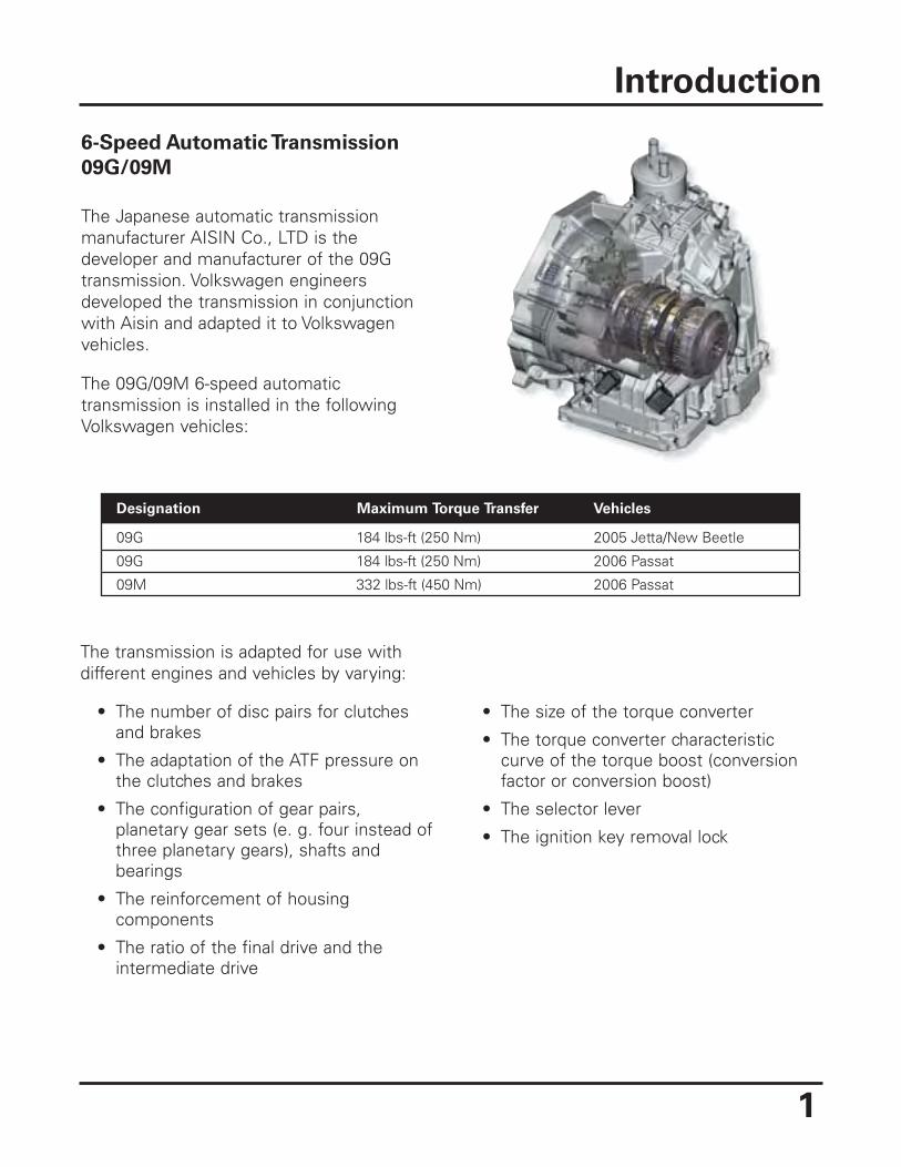
The Japanese automatic transmissionmanufacturer AISIN Co., LTD is thedeveloper and manufacturer of the 09Gtransmission. Volkswagen engineersdeveloped the transmission in conjunctionwith Aisin and adapted it to Volkswagenvehicles.
The 09G/09M 6-speed automatictransmission is installed in the followingVolkswagen vehicles:
• The size of the torque converter
• The torque converter characteristiccurve of the torque boost (conversionfactor or conversion boost)
• The selector lever
• The ignition key removal lock
Introduction
Designation
09G
09G
09M
184 lbs-ft (250 Nm)
184 lbs-ft (250 Nm)
332 lbs-ft (450 Nm)
2005 Jetta/New Beetle
2006 Passat
2006 Passat
Maximum Torque Transfer Vehicles
The transmission is adapted for use withdifferent engines and vehicles by varying:
• The number of disc pairs for clutchesand brakes
• The adaptation of the ATF pressure onthe clutches and brakes
• The configuration of gear pairs,planetary gear sets (e. g. four instead ofthree planetary gears), shafts andbearings
• The reinforcement of housingcomponents
• The ratio of the final drive and theintermediate drive
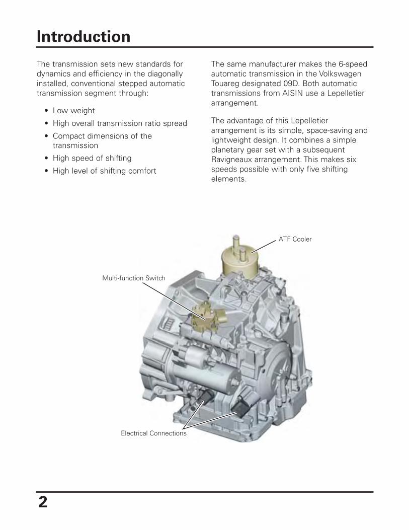
The transmission sets new standards fordynamics and efficiency in the diagonallyinstalled, conventional stepped automatictransmission segment through:
• Low weight
• High overall transmission ratio spread
• Compact dimensions of thetransmission
• High speed of shifting
• High level of shifting comfort
The same manufacturer makes the 6-speedautomatic transmission in the VolkswagenTouareg designated 09D. Both automatictransmissions from AISIN use a Lepelletierarrangement.
The advantage of this Lepelletierarrangement is its simple, space-saving andlightweight design. It combines a simpleplanetary gear set with a subsequentRavigneaux arrangement. This makes sixspeeds possible with only five shiftingelements.
Introduction
2
ATF Cooler
Multi-function Switch
Electrical Connections
3
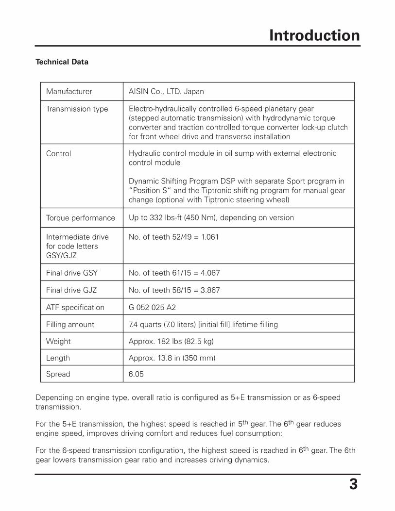
Technical Data
Depending on engine type, overall ratio is configured as 5+E transmission or as 6-speedtransmission.
For the 5+E transmission, the highest speed is reached in 5th gear. The 6th gear reducesengine speed, improves driving comfort and reduces fuel consumption:
For the 6-speed transmission configuration, the highest speed is reached in 6th gear. The 6thgear lowers transmission gear ratio and increases driving dynamics.
Introduction
Manufacturer
Transmission type
Control
Torque performance
Final drive GSY
Final drive GJZ
ATF specification
Filling amount
Weight
Length
Spread
G 052 025 A2
7.4 quarts (7.0 liters) [initial fill] lifetime filling
Approx. 182 lbs (82.5 kg)
Approx. 13.8 in (350 mm)
6.05
Intermediate drivefor code lettersGSY/GJZ
Electro-hydraulically controlled 6-speed planetary gear(stepped automatic transmission) with hydrodynamic torqueconverter and traction controlled torque converter lock-up clutchfor front wheel drive and transverse installation
Hydraulic control module in oil sump with external electroniccontrol module
Dynamic Shifting Program DSP with separate Sport program in“Position S“ and the Tiptronic shifting program for manual gearchange (optional with Tiptronic steering wheel)
Up to 332 lbs-ft (450 Nm), depending on version
No. of teeth 52/49 = 1.061
No. of teeth 61/15 = 4.067
No. of teeth 58/15 = 3.867
AISIN Co., LTD. Japan
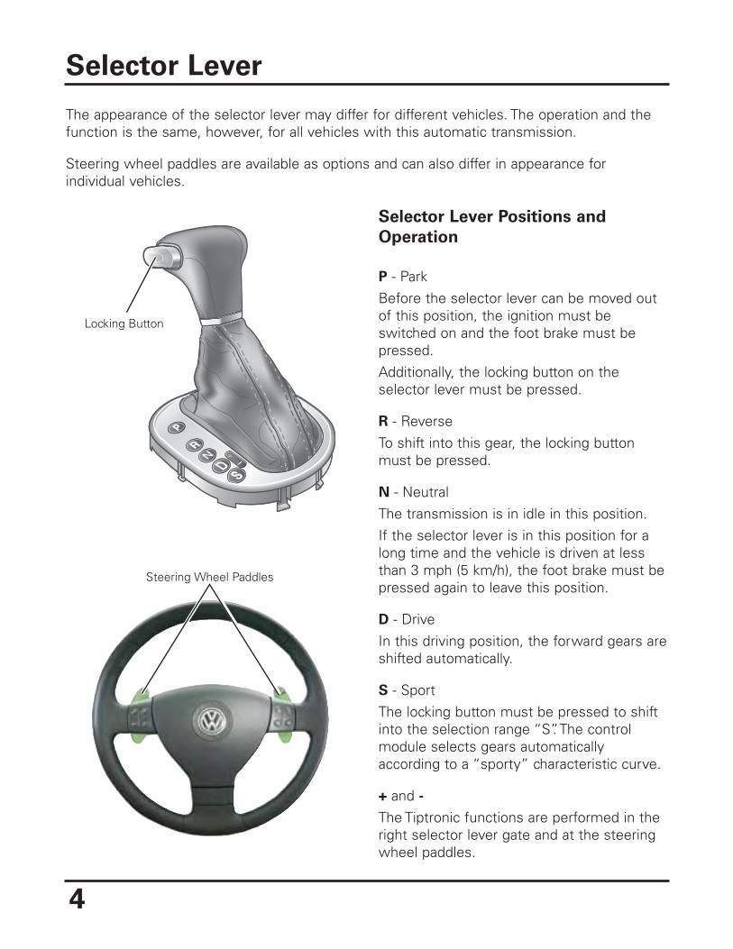
The appearance of the selector lever may differ for different vehicles. The operation and thefunction is the same, however, for all vehicles with this automatic transmission.
Steering wheel paddles are available as options and can also differ in appearance forindividual vehicles.
Selector Lever Positions and
Operation
P - ParkBefore the selector lever can be moved outof this position, the ignition must beswitched on and the foot brake must bepressed.Additionally, the locking button on theselector lever must be pressed.
R - ReverseTo shift into this gear, the locking buttonmust be pressed.
N - NeutralThe transmission is in idle in this position.If the selector lever is in this position for along time and the vehicle is driven at lessthan 3 mph (5 km/h), the foot brake must bepressed again to leave this position.
D - DriveIn this driving position, the forward gears areshifted automatically.
S - SportThe locking button must be pressed to shiftinto the selection range “S”. The controlmodule selects gears automaticallyaccording to a “sporty” characteristic curve.
+ and -The Tiptronic functions are performed in theright selector lever gate and at the steeringwheel paddles.
Selector Lever
4
Locking Button
Steering Wheel Paddles
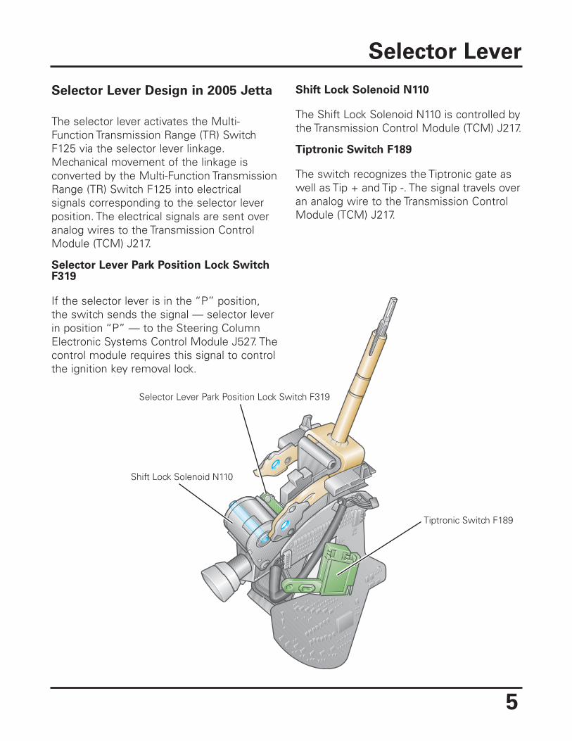
Selector Lever Park Position Lock Switch F319
Tiptronic Switch F189
Shift Lock Solenoid N110
5
Selector Lever Design in 2005 Jetta
The selector lever activates the Multi-Function Transmission Range (TR) SwitchF125 via the selector lever linkage.Mechanical movement of the linkage isconverted by the Multi-Function TransmissionRange (TR) Switch F125 into electricalsignals corresponding to the selector leverposition. The electrical signals are sent overanalog wires to the Transmission ControlModule (TCM) J217.
Selector Lever Park Position Lock SwitchF319
If the selector lever is in the “P” position,the switch sends the signal — selector leverin position “P” — to the Steering ColumnElectronic Systems Control Module J527. Thecontrol module requires this signal to controlthe ignition key removal lock.
Shift Lock Solenoid N110
The Shift Lock Solenoid N110 is controlled bythe Transmission Control Module (TCM) J217.
Tiptronic Switch F189
The switch recognizes the Tiptronic gate aswell as Tip + and Tip -. The signal travels overan analog wire to the Transmission ControlModule (TCM) J217.
Selector Lever
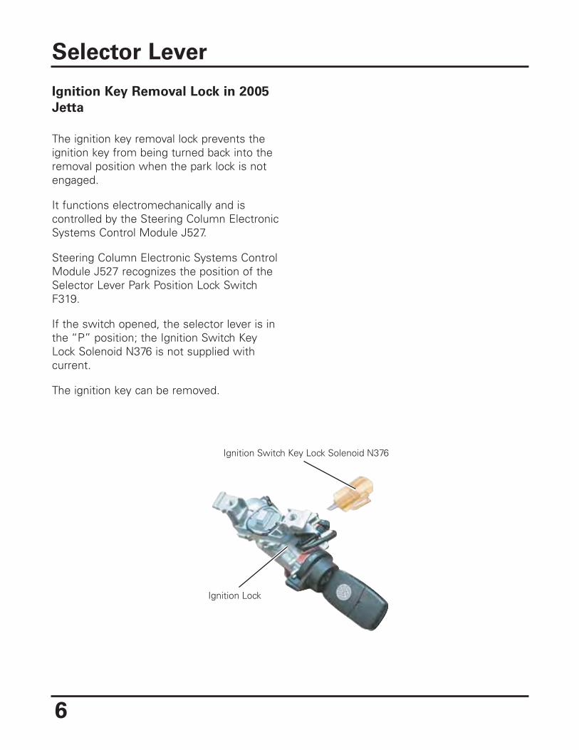
Ignition Switch Key Lock Solenoid N376
Ignition Lock
Ignition Key Removal Lock in 2005
Jetta
The ignition key removal lock prevents theignition key from being turned back into theremoval position when the park lock is notengaged.
It functions electromechanically and iscontrolled by the Steering Column ElectronicSystems Control Module J527.
Steering Column Electronic Systems ControlModule J527 recognizes the position of theSelector Lever Park Position Lock SwitchF319.
If the switch opened, the selector lever is inthe “P” position; the Ignition Switch KeyLock Solenoid N376 is not supplied withcurrent.
The ignition key can be removed.
Selector Lever
6
7
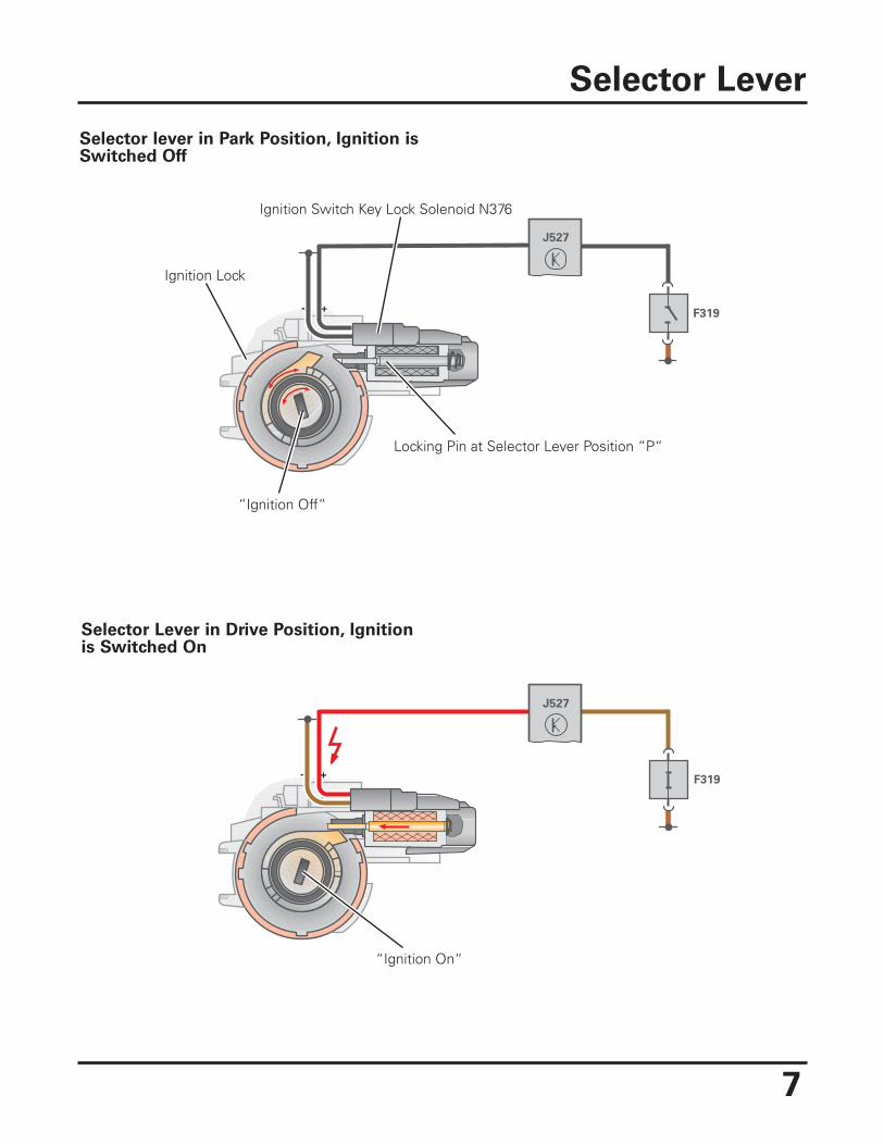
Selector lever in Park Position, Ignition isSwitched Off
Selector Lever
+F319
J527
-
Ignition Switch Key Lock Solenoid N376
Ignition Lock
“Ignition Off“
Locking Pin at Selector Lever Position “P“
Selector Lever in Drive Position, Ignitionis Switched On
- +F319
J527
“Ignition On“
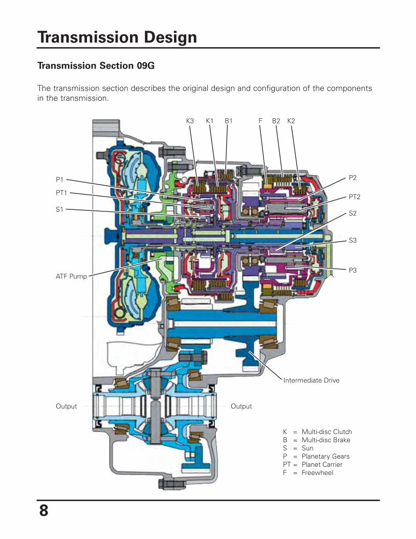
Transmission Section 09G
The transmission section describes the original design and configuration of the componentsin the transmission.
Transmission Design
8
K3 K1 B1 F B2 K2
P2
PT2
S2
S3
P3
P1
PT1
S1
ATF Pump
Output Output
Intermediate Drive
K = Multi-disc ClutchB = Multi-disc BrakeS = SunP = Planetary GearsPT = Planet CarrierF = Freewheel
9
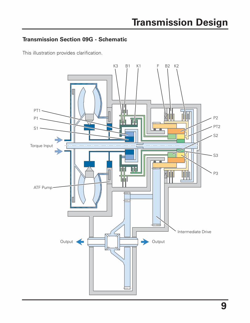
Transmission Section 09G - Schematic
This illustration provides clarification.
Transmission Design
K3 K1B1 F B2 K2
P2
PT2
S2
S3
P3
P1
PT1
S1
ATF Pump
Output Output
Intermediate Drive
Torque Input
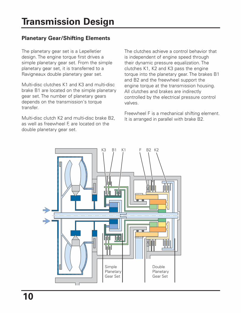
Planetary Gear/Shifting Elements
The planetary gear set is a Lepelletierdesign. The engine torque first drives asimple planetary gear set. From the simpleplanetary gear set, it is transferred to aRavigneaux double planetary gear set.
Multi-disc clutches K1 and K3 and multi-discbrake B1 are located on the simple planetarygear set. The number of planetary gearsdepends on the transmission's torquetransfer.
Multi-disc clutch K2 and multi-disc brake B2,as well as freewheel F, are located on thedouble planetary gear set.
The clutches achieve a control behavior thatis independent of engine speed throughtheir dynamic pressure equalization. Theclutches K1, K2 and K3 pass the enginetorque into the planetary gear. The brakes B1and B2 and the freewheel support theengine torque at the transmission housing.All clutches and brakes are indirectlycontrolled by the electrical pressure controlvalves.
Freewheel F is a mechanical shifting element.It is arranged in parallel with brake B2.
Transmission Design
10
K3 K1B1 F B2
DoublePlanetaryGear Set
SimplePlanetaryGear Set
K2
11
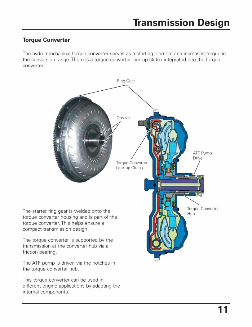
Torque Converter
The hydro-mechanical torque converter serves as a starting element and increases torque inthe conversion range. There is a torque converter lock-up clutch integrated into the torqueconverter.
Transmission Design
Ring Gear
Groove
Torque ConverterLock-up Clutch
ATF PumpDrive
Torque ConverterHubThe starter ring gear is welded onto the
torque converter housing and is part of thetorque converter. This helps ensure acompact transmission design.
The torque converter is supported by thetransmission at the converter hub via afriction bearing.
The ATF pump is driven via the notches inthe torque converter hub.
This torque converter can be used indifferent engine applications by adapting theinternal components.
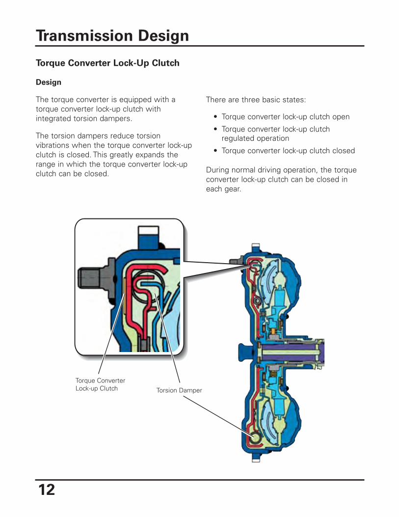
Torque Converter Lock-Up Clutch
Design
The torque converter is equipped with atorque converter lock-up clutch withintegrated torsion dampers.
The torsion dampers reduce torsionvibrations when the torque converter lock-upclutch is closed. This greatly expands therange in which the torque converter lock-upclutch can be closed.
There are three basic states:
• Torque converter lock-up clutch open
• Torque converter lock-up clutchregulated operation
• Torque converter lock-up clutch closed
During normal driving operation, the torqueconverter lock-up clutch can be closed ineach gear.
Transmission Design
12
Torque ConverterLock-up Clutch Torsion Damper
13
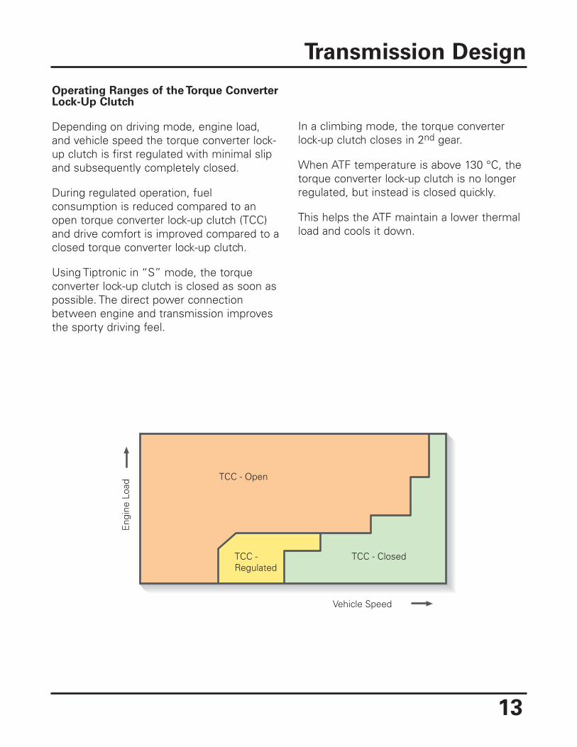
Operating Ranges of the Torque ConverterLock-Up Clutch
Depending on driving mode, engine load,and vehicle speed the torque converter lock-up clutch is first regulated with minimal slipand subsequently completely closed.
During regulated operation, fuelconsumption is reduced compared to anopen torque converter lock-up clutch (TCC)and drive comfort is improved compared to aclosed torque converter lock-up clutch.
Using Tiptronic in “S” mode, the torqueconverter lock-up clutch is closed as soon aspossible. The direct power connectionbetween engine and transmission improvesthe sporty driving feel.
In a climbing mode, the torque converterlock-up clutch closes in 2nd gear.
When ATF temperature is above 130 °C, thetorque converter lock-up clutch is no longerregulated, but instead is closed quickly.
This helps the ATF maintain a lower thermalload and cools it down.
Transmission Design
TCC - Open
Vehicle Speed
Eng
ine
Load
TCC -Regulated
TCC - Closed
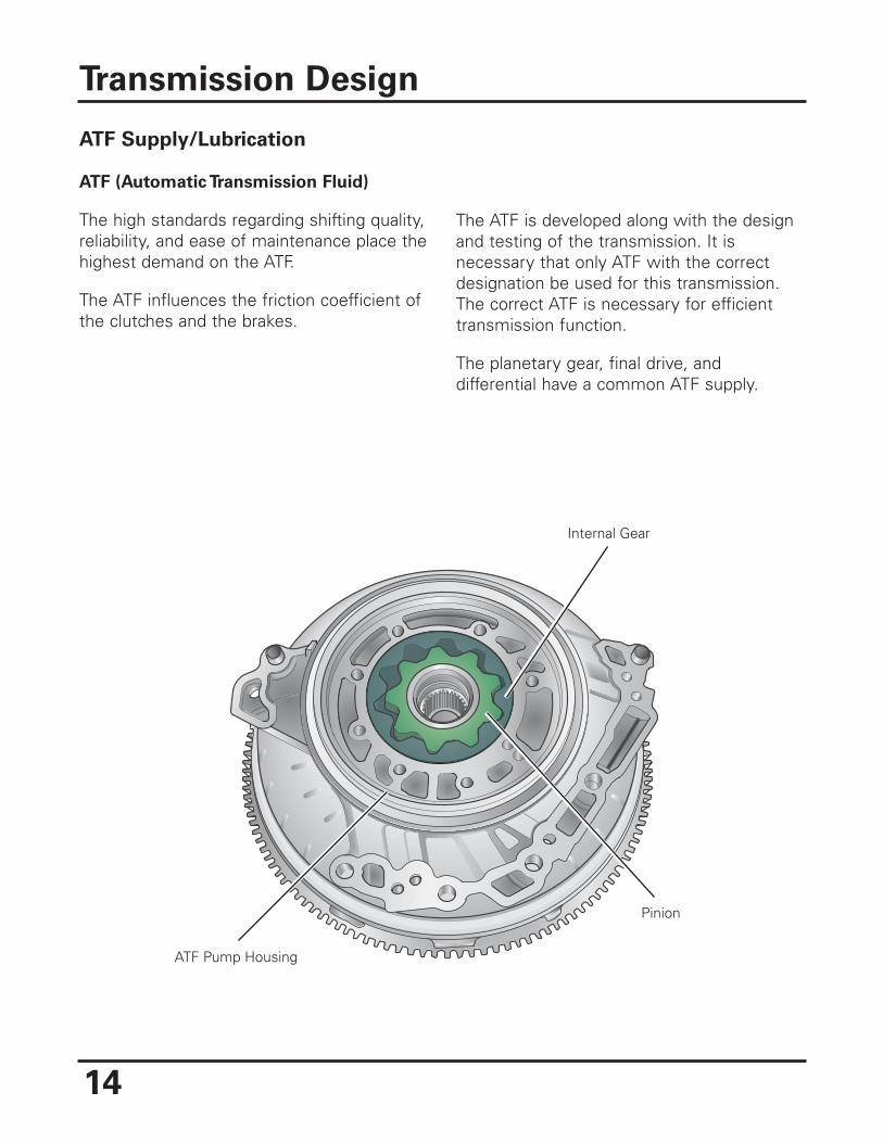
ATF Supply/Lubrication
ATF (Automatic Transmission Fluid)
The high standards regarding shifting quality,reliability, and ease of maintenance place thehighest demand on the ATF.
The ATF influences the friction coefficient ofthe clutches and the brakes.
The ATF is developed along with the designand testing of the transmission. It isnecessary that only ATF with the correctdesignation be used for this transmission.The correct ATF is necessary for efficienttransmission function.
The planetary gear, final drive, anddifferential have a common ATF supply.
Transmission Design
14
ATF Pump Housing
Pinion
Internal Gear
Internal Gear
Drivers
Pinion
15
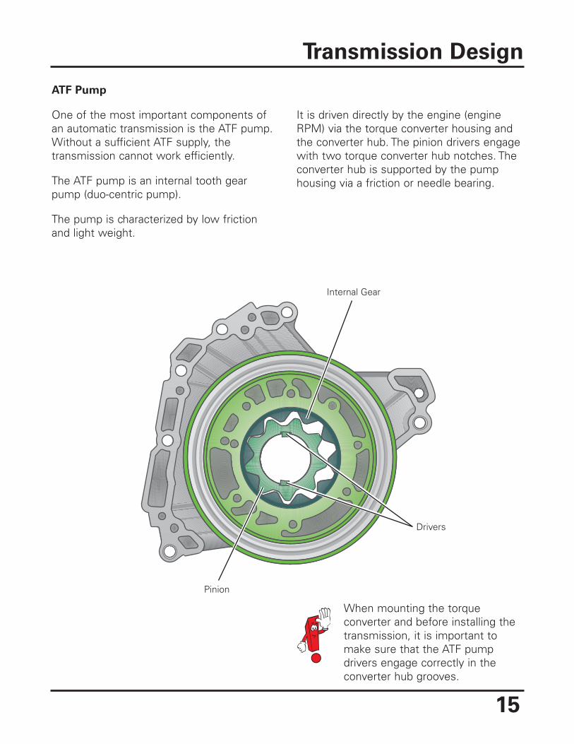
ATF Pump
One of the most important components ofan automatic transmission is the ATF pump.Without a sufficient ATF supply, thetransmission cannot work efficiently.
The ATF pump is an internal tooth gearpump (duo-centric pump).
The pump is characterized by low frictionand light weight.
It is driven directly by the engine (engineRPM) via the torque converter housing andthe converter hub. The pinion drivers engagewith two torque converter hub notches. Theconverter hub is supported by the pumphousing via a friction or needle bearing.
Transmission Design
When mounting the torqueconverter and before installing thetransmission, it is important tomake sure that the ATF pumpdrivers engage correctly in theconverter hub grooves.
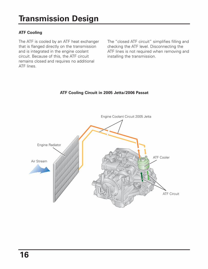
ATF Cooling
The ATF is cooled by an ATF heat exchangerthat is flanged directly on the transmissionand is integrated in the engine coolantcircuit. Because of this, the ATF circuitremains closed and requires no additionalATF lines.
The “closed ATF circuit” simplifies filling andchecking the ATF level. Disconnecting theATF lines is not required when removing andinstalling the transmission.
Transmission Design
16
ATF Cooling Circuit in 2005 Jetta/2006 Passat
Air Stream
Engine Radiator
ATF Cooler
ATF Circuit
Engine Coolant Circuit 2005 Jetta
17
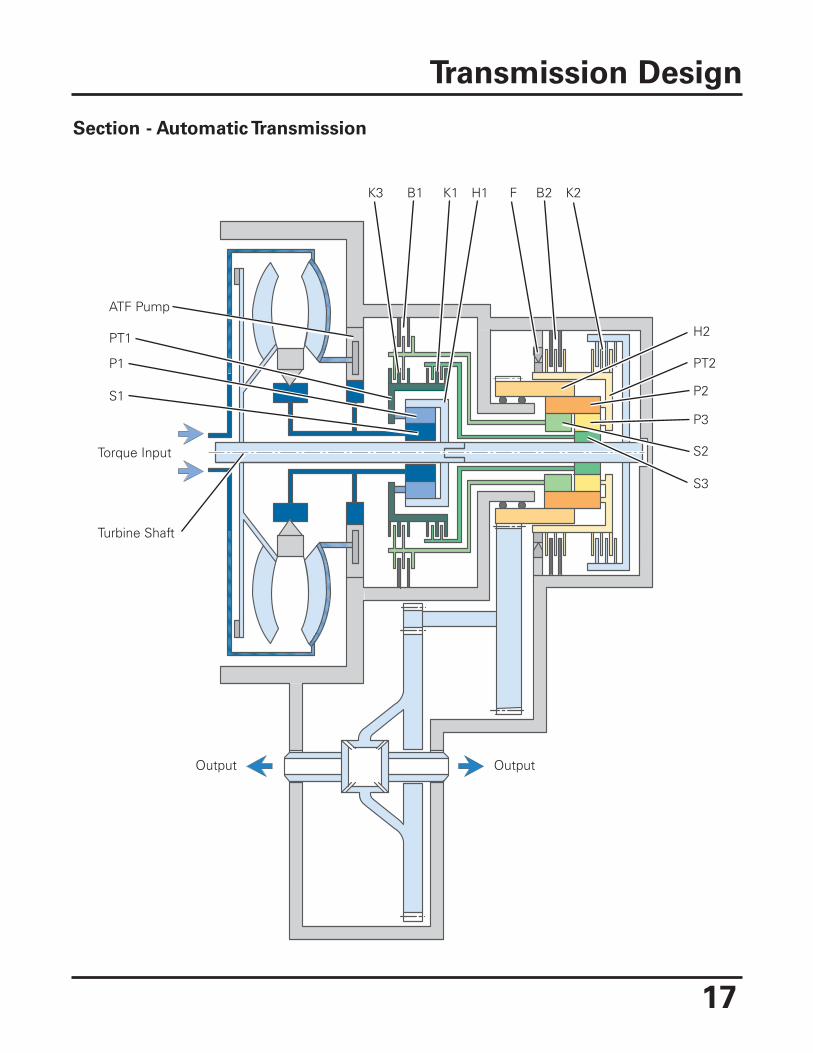
Section - Automatic Transmission
Transmission Design
K3 K1B1 F B2 K2
P2
PT2
P3
S2
S3
P1
PT1
S1
ATF Pump
Output Output
H1
H2
Torque Input
Turbine Shaft
18
Transmission Design
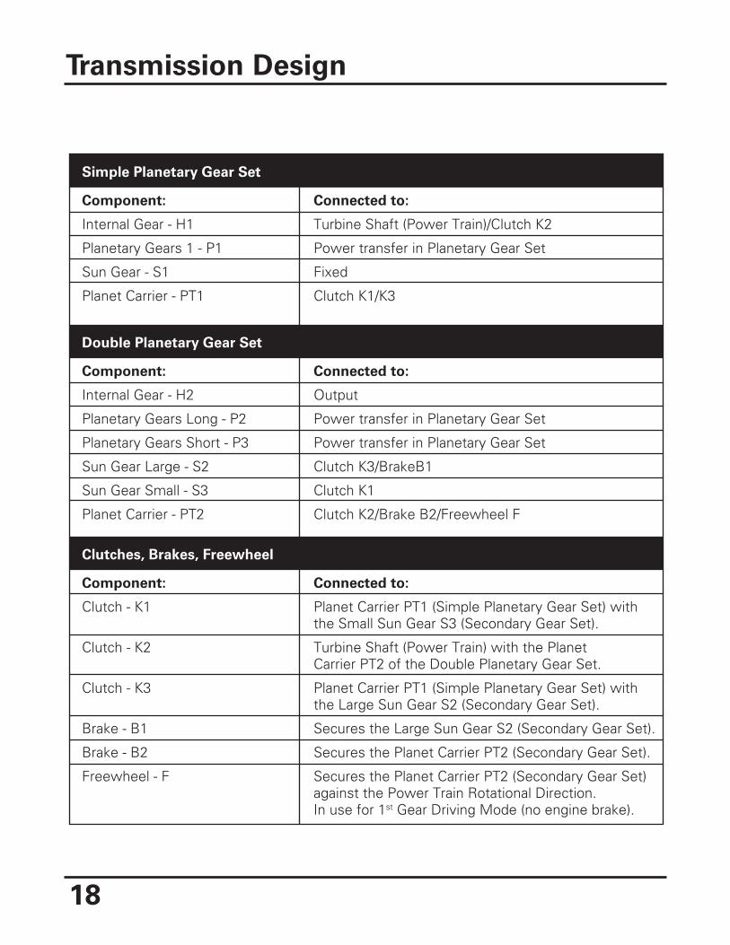
Simple Planetary Gear Set
Component:
Internal Gear - H1
Planetary Gears 1 - P1
Sun Gear - S1
Planet Carrier - PT1
Connected to:
Turbine Shaft (Power Train)/Clutch K2
Power transfer in Planetary Gear Set
Fixed
Clutch K1/K3
Double Planetary Gear Set
Component:
Internal Gear - H2
Planetary Gears Long - P2
Planetary Gears Short - P3
Sun Gear Large - S2
Sun Gear Small - S3
Planet Carrier - PT2
Connected to:
Output
Power transfer in Planetary Gear Set
Power transfer in Planetary Gear Set
Clutch K3/BrakeB1
Clutch K1
Clutch K2/Brake B2/Freewheel F
Clutches, Brakes, Freewheel
Component:
Clutch - K1
Clutch - K2
Clutch - K3
Brake - B1
Brake - B2
Freewheel - F
Connected to:
Planet Carrier PT1 (Simple Planetary Gear Set) withthe Small Sun Gear S3 (Secondary Gear Set).
Turbine Shaft (Power Train) with the PlanetCarrier PT2 of the Double Planetary Gear Set.
Planet Carrier PT1 (Simple Planetary Gear Set) withthe Large Sun Gear S2 (Secondary Gear Set).
Secures the Large Sun Gear S2 (Secondary Gear Set).
Secures the Planet Carrier PT2 (Secondary Gear Set).
Secures the Planet Carrier PT2 (Secondary Gear Set)against the Power Train Rotational Direction.In use for 1st Gear Driving Mode (no engine brake).
19
Park Lock Wheel
Locking Pawl
Pin
CompressionSpring
ShaftIntermediate Drive
Locking Pawl
LinkagePark Lock Wheel CompressionSpring
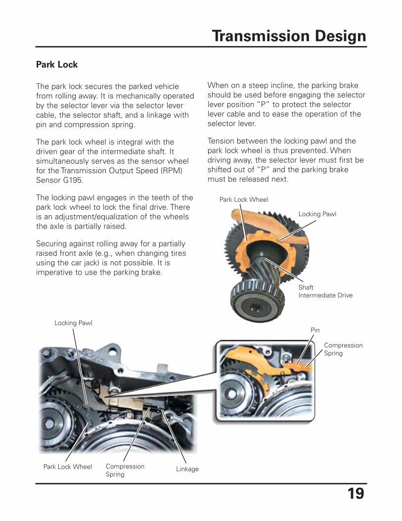
Park Lock
The park lock secures the parked vehiclefrom rolling away. It is mechanically operatedby the selector lever via the selector levercable, the selector shaft, and a linkage withpin and compression spring.
The park lock wheel is integral with thedriven gear of the intermediate shaft. Itsimultaneously serves as the sensor wheelfor the Transmission Output Speed (RPM)Sensor G195.
The locking pawl engages in the teeth of thepark lock wheel to lock the final drive. Thereis an adjustment/equalization of the wheelsthe axle is partially raised.
Securing against rolling away for a partiallyraised front axle (e.g., when changing tiresusing the car jack) is not possible. It isimperative to use the parking brake.
When on a steep incline, the parking brakeshould be used before engaging the selectorlever position “P” to protect the selectorlever cable and to ease the operation of theselector lever.
Tension between the locking pawl and thepark lock wheel is thus prevented. Whendriving away, the selector lever must first beshifted out of “P” and the parking brakemust be released next.
Transmission Design
20
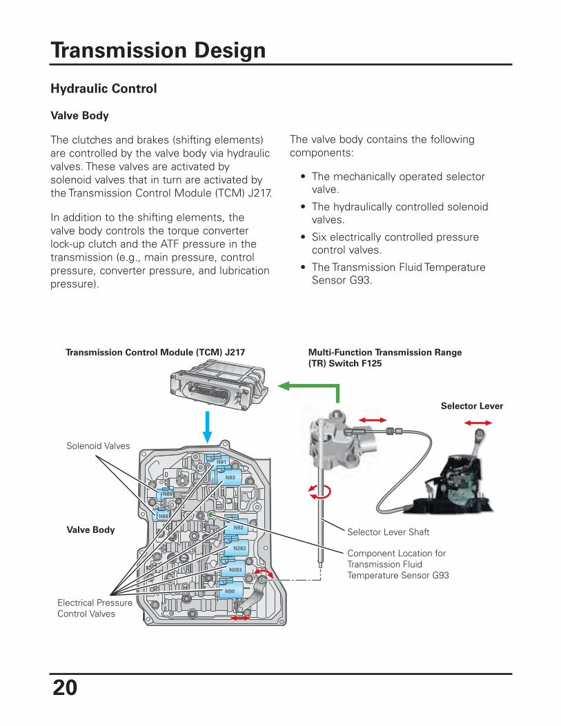
Hydraulic Control
Valve Body
The clutches and brakes (shifting elements)are controlled by the valve body via hydraulicvalves. These valves are activated bysolenoid valves that in turn are activated bythe Transmission Control Module (TCM) J217.
In addition to the shifting elements, thevalve body controls the torque converterlock-up clutch and the ATF pressure in thetransmission (e.g., main pressure, controlpressure, converter pressure, and lubricationpressure).
The valve body contains the followingcomponents:
• The mechanically operated selectorvalve.
• The hydraulically controlled solenoidvalves.
• Six electrically controlled pressurecontrol valves.
• The Transmission Fluid TemperatureSensor G93.
Transmission Design
N89
N88
N89
N92
N93
N91
N282
N283
N90
Solenoid Valves
Selector Lever Shaft
Component Location forTransmission FluidTemperature Sensor G93
Valve Body
Electrical Pressure Control Valves
Selector Lever
Transmission Control Module (TCM) J217 Multi-Function Transmission Range
(TR) Switch F125
21
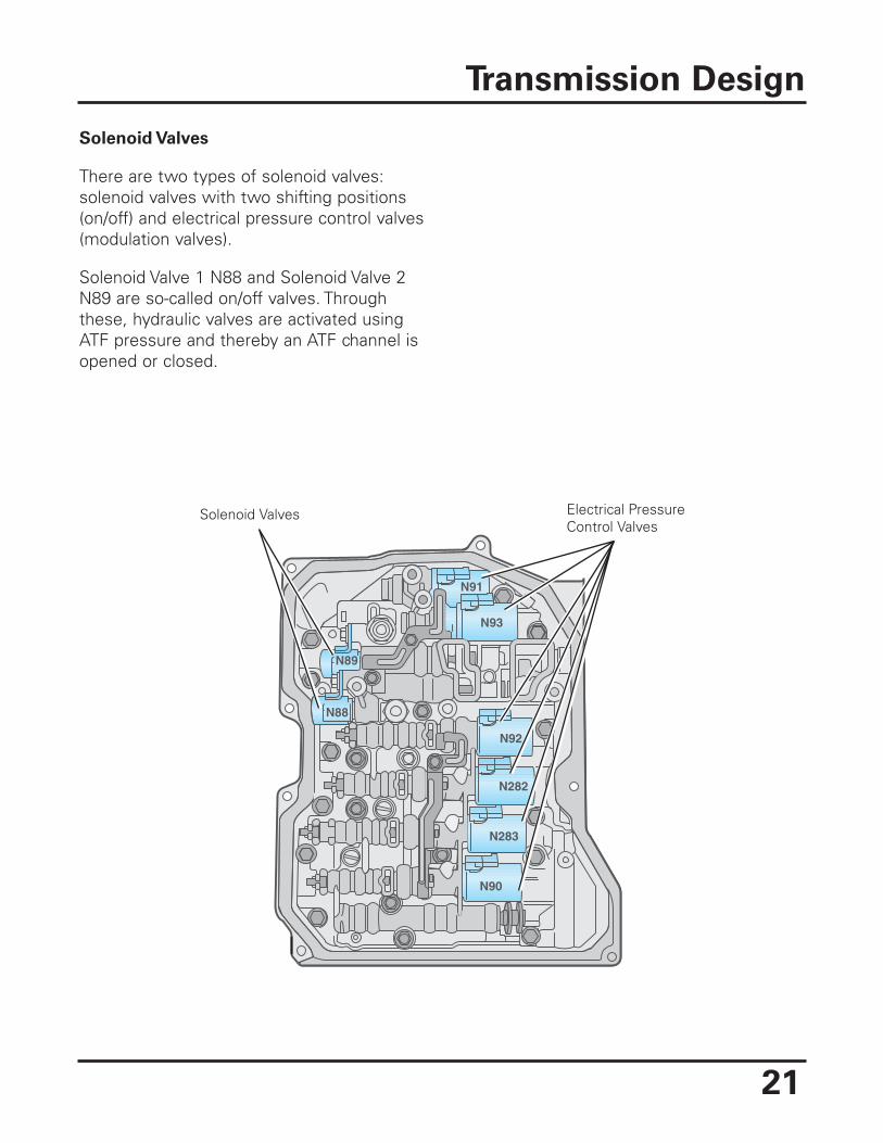
Solenoid Valves
There are two types of solenoid valves:solenoid valves with two shifting positions(on/off) and electrical pressure control valves(modulation valves).
Solenoid Valve 1 N88 and Solenoid Valve 2N89 are so-called on/off valves. Throughthese, hydraulic valves are activated usingATF pressure and thereby an ATF channel isopened or closed.
Transmission Design
N89
N88
N89
N92
N93
N91
N282
N283
N90
Solenoid Valves Electrical PressureControl Valves
Electrical Pressure Control Valves
Electrical pressure control valves convert anelectrical current into a proportional hydrauliccontrol pressure. There are two types ofpressure control valves installed.
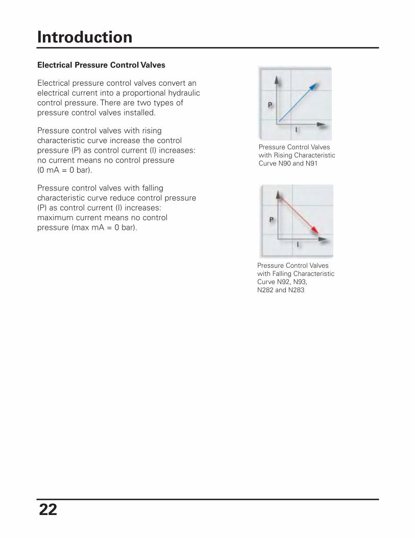
Pressure control valves with risingcharacteristic curve increase the controlpressure (P) as control current (I) increases:no current means no control pressure(0 mA = 0 bar).
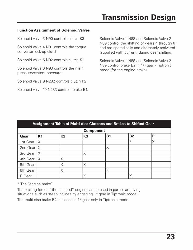
Pressure control valves with fallingcharacteristic curve reduce control pressure(P) as control current (I) increases:maximum current means no controlpressure (max mA = 0 bar).
Introduction
22
Pressure Control Valveswith Rising CharacteristicCurve N90 and N91
Pressure Control Valveswith Falling CharacteristicCurve N92, N93,N282 and N283
23
Function Assignment of Solenoid Valves
Solenoid Valve 3 N90 controls clutch K3
Solenoid Valve 4 N91 controls the torqueconverter lock-up clutch
Solenoid Valve 5 N92 controls clutch K1
Solenoid Valve 6 N93 controls the mainpressure/system pressure
Solenoid Valve 9 N282 controls clutch K2
Solenoid Valve 10 N283 controls brake B1.
Solenoid Valve 1 N88 and Solenoid Valve 2N89 control the shifting of gears 4 through 6and are sporadically and alternately activated(supplied with current) during gear shifting.
Solenoid Valve 1 N88 and Solenoid Valve 2N89 control brake B2 in 1st gear - Tiptronicmode (for the engine brake).
Transmission Design
Assignment Table of Multi-disc Clutches and Brakes to Shifted Gear
Gear
1st Gear2nd Gear3rd Gear4th Gear5th Gear6th GearR Gear
Component
K2
XXX
K3
X
X
X
B1
X
X
B2
*
X
F
XK1
XXXX
* The “engine brake”The braking force of the “shifted” engine can be used in particular drivingsituations such as steep inclines by engaging 1st gear in Tiptronic mode.The multi-disc brake B2 is closed in 1st gear only in Tiptronic mode.
24
P1 S1 K1 H1 F
H2PT1
TorqueInput
Turbine Shaft
To DriveshaftTo Driveshaft
PT2
S3
Output Toothed Gear
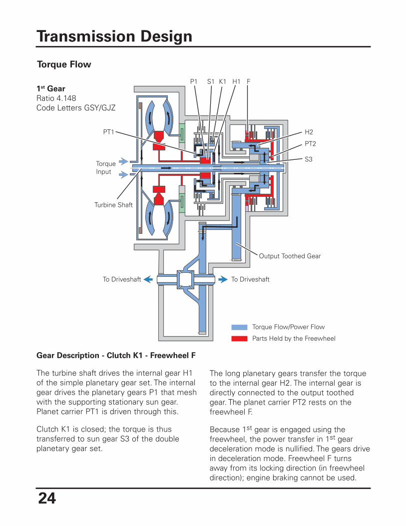
1st Gear
Ratio 4.148 Code Letters GSY/GJZ
Torque Flow/Power Flow
Parts Held by the Freewheel
Gear Description - Clutch K1 - Freewheel F
The turbine shaft drives the internal gear H1of the simple planetary gear set. The internalgear drives the planetary gears P1 that meshwith the supporting stationary sun gear.Planet carrier PT1 is driven through this.
Clutch K1 is closed; the torque is thustransferred to sun gear S3 of the doubleplanetary gear set.
The long planetary gears transfer the torqueto the internal gear H2. The internal gear isdirectly connected to the output toothedgear. The planet carrier PT2 rests on thefreewheel F.
Because 1st gear is engaged using thefreewheel, the power transfer in 1st geardeceleration mode is nullified. The gears drivein deceleration mode. Freewheel F turnsaway from its locking direction (in freewheeldirection); engine braking cannot be used.
Transmission Design
Torque Flow
25
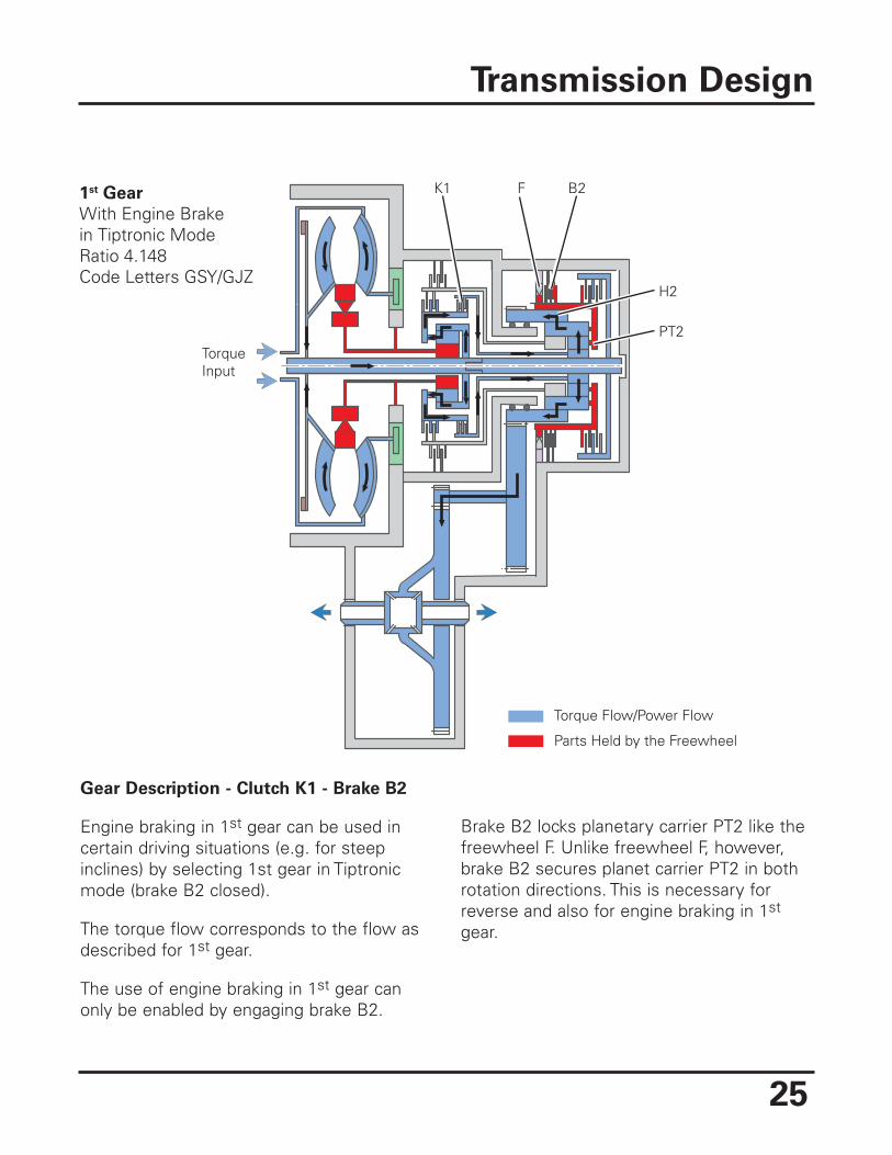
Gear Description - Clutch K1 - Brake B2
Engine braking in 1st gear can be used incertain driving situations (e.g. for steepinclines) by selecting 1st gear in Tiptronicmode (brake B2 closed).
The torque flow corresponds to the flow asdescribed for 1st gear.
The use of engine braking in 1st gear canonly be enabled by engaging brake B2.
Brake B2 locks planetary carrier PT2 like thefreewheel F. Unlike freewheel F, however,brake B2 secures planet carrier PT2 in bothrotation directions. This is necessary forreverse and also for engine braking in 1st
gear.
Transmission Design
K1 F B2
H2
PT2TorqueInput
Torque Flow/Power Flow
Parts Held by the Freewheel
1st Gear
With Engine Brakein Tiptronic ModeRatio 4.148 Code Letters GSY/GJZ
26
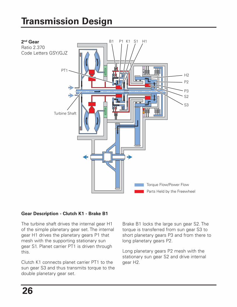
Gear Description - Clutch K1 - Brake B1
The turbine shaft drives the internal gear H1of the simple planetary gear set. The internalgear H1 drives the planetary gears P1 thatmesh with the supporting stationary sungear S1. Planet carrier PT1 is driven throughthis.
Clutch K1 connects planet carrier PT1 to thesun gear S3 and thus transmits torque to thedouble planetary gear set.
Brake B1 locks the large sun gear S2. Thetorque is transferred from sun gear S3 toshort planetary gears P3 and from there tolong planetary gears P2.
Long planetary gears P2 mesh with thestationary sun gear S2 and drive internalgear H2.
Transmission Design
Torque Flow/Power Flow
Parts Held by the Freewheel
B1 P1 K1 S1 H1
H2
P2
PT1
P3S2
S3
Turbine Shaft
2nd Gear
Ratio 2.370 Code Letters GSY/GJZ
27
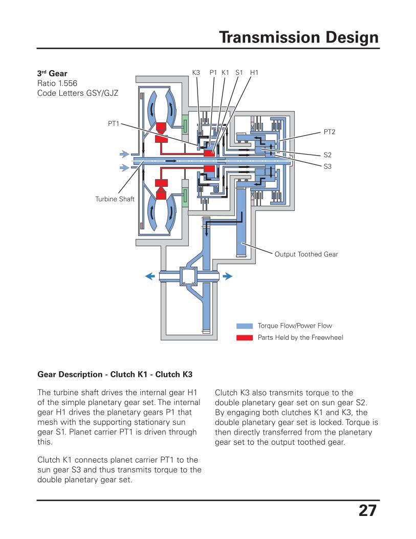
Gear Description - Clutch K1 - Clutch K3
The turbine shaft drives the internal gear H1of the simple planetary gear set. The internalgear H1 drives the planetary gears P1 thatmesh with the supporting stationary sungear S1. Planet carrier PT1 is driven throughthis.
Clutch K1 connects planet carrier PT1 to thesun gear S3 and thus transmits torque to thedouble planetary gear set.
Clutch K3 also transmits torque to thedouble planetary gear set on sun gear S2.By engaging both clutches K1 and K3, thedouble planetary gear set is locked. Torque isthen directly transferred from the planetarygear set to the output toothed gear.
Transmission Design
K3 P1 K1 S1 H1
PT2
S2
PT1
S3
Output Toothed Gear
Turbine Shaft
Torque Flow/Power Flow
Parts Held by the Freewheel
3rd Gear
Ratio 1.556Code Letters GSY/GJZ
28
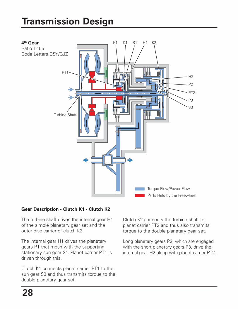
Gear Description - Clutch K1 - Clutch K2
The turbine shaft drives the internal gear H1of the simple planetary gear set and theouter disc carrier of clutch K2.
The internal gear H1 drives the planetarygears P1 that mesh with the supportingstationary sun gear S1. Planet carrier PT1 isdriven through this.
Clutch K1 connects planet carrier PT1 to thesun gear S3 and thus transmits torque to thedouble planetary gear set.
Clutch K2 connects the turbine shaft toplanet carrier PT2 and thus also transmitstorque to the double planetary gear set.
Long planetary gears P2, which are engagedwith the short planetary gears P3, drive theinternal gear H2 along with planet carrier PT2.
Transmission Design
Torque Flow/Power Flow
Parts Held by the Freewheel
Turbine Shaft
P1 K1 S1 H1 K2
H2
P2
PT2
P3
S3
PT1
4th Gear
Ratio 1.155Code Letters GSY/GJZ
29
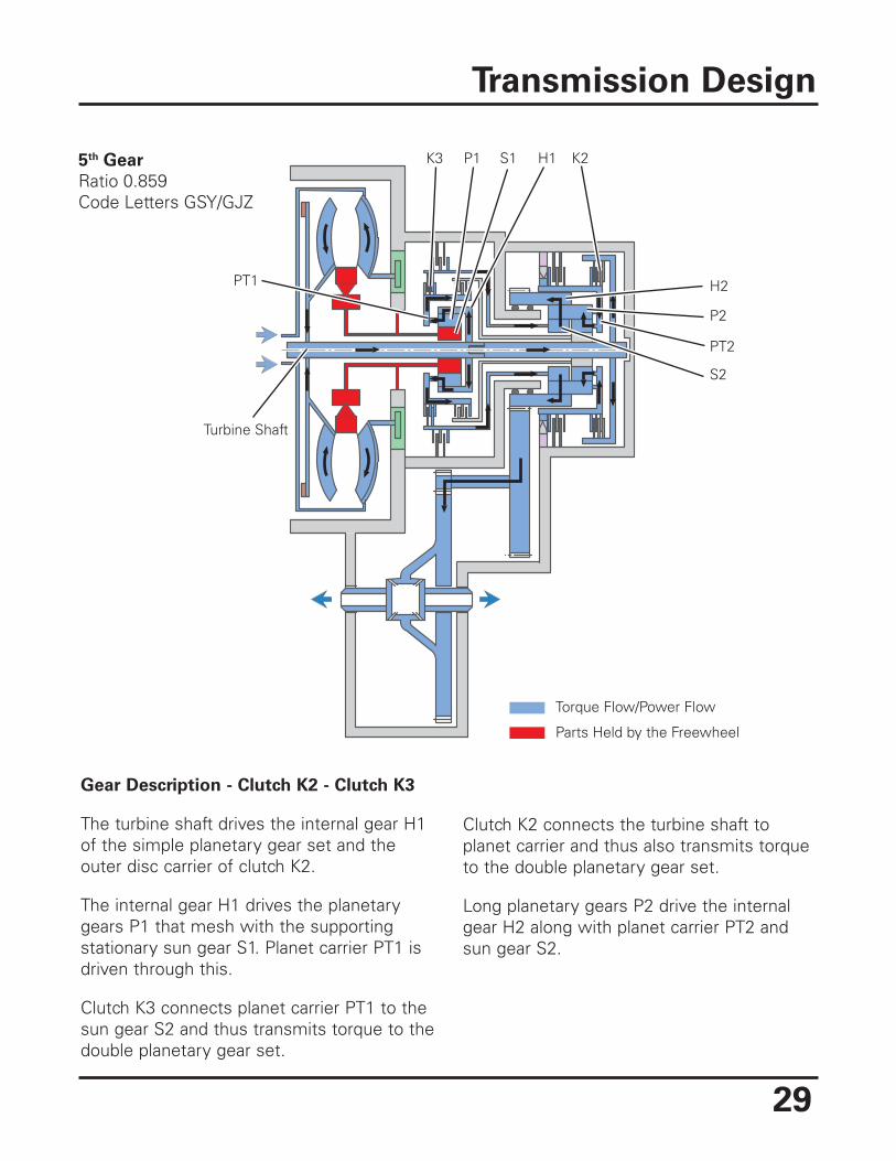
Gear Description - Clutch K2 - Clutch K3
The turbine shaft drives the internal gear H1of the simple planetary gear set and theouter disc carrier of clutch K2.
The internal gear H1 drives the planetarygears P1 that mesh with the supportingstationary sun gear S1. Planet carrier PT1 isdriven through this.
Clutch K3 connects planet carrier PT1 to thesun gear S2 and thus transmits torque to thedouble planetary gear set.
Clutch K2 connects the turbine shaft toplanet carrier and thus also transmits torqueto the double planetary gear set.
Long planetary gears P2 drive the internalgear H2 along with planet carrier PT2 andsun gear S2.
Transmission Design
Torque Flow/Power Flow
Parts Held by the Freewheel
Turbine Shaft
K3 P1 S1 H1 K2
H2
P2
PT2
S2
PT1
5th Gear
Ratio 0.859Code Letters GSY/GJZ
30
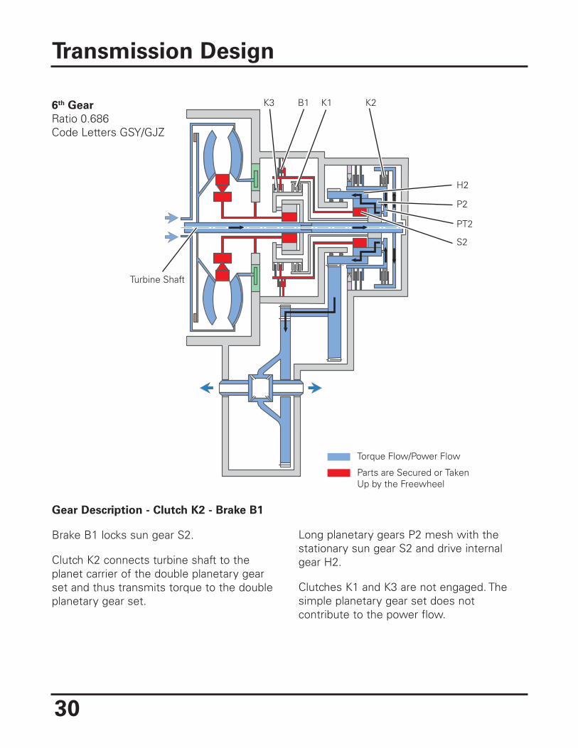
Gear Description - Clutch K2 - Brake B1
Brake B1 locks sun gear S2.
Clutch K2 connects turbine shaft to theplanet carrier of the double planetary gearset and thus transmits torque to the doubleplanetary gear set.
Long planetary gears P2 mesh with thestationary sun gear S2 and drive internalgear H2.
Clutches K1 and K3 are not engaged. Thesimple planetary gear set does notcontribute to the power flow.
Transmission Design
Torque Flow/Power Flow
Parts are Secured or TakenUp by the Freewheel
Turbine Shaft
K3 B1 K1 K2
H2
P2
PT2
S2
6th Gear
Ratio 0.686Code Letters GSY/GJZ
31
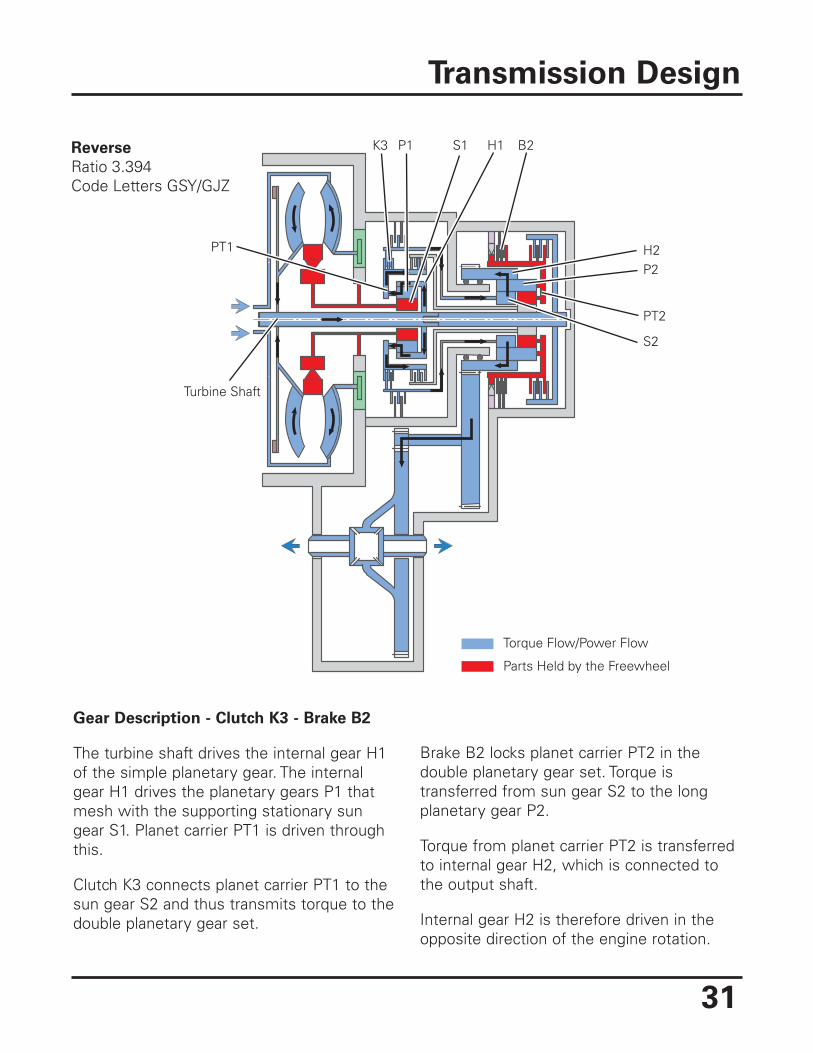
Gear Description - Clutch K3 - Brake B2
The turbine shaft drives the internal gear H1of the simple planetary gear. The internalgear H1 drives the planetary gears P1 thatmesh with the supporting stationary sungear S1. Planet carrier PT1 is driven throughthis.
Clutch K3 connects planet carrier PT1 to thesun gear S2 and thus transmits torque to thedouble planetary gear set.
Brake B2 locks planet carrier PT2 in thedouble planetary gear set. Torque istransferred from sun gear S2 to the longplanetary gear P2.
Torque from planet carrier PT2 is transferredto internal gear H2, which is connected tothe output shaft.
Internal gear H2 is therefore driven in theopposite direction of the engine rotation.
Transmission Design
Torque Flow/Power Flow
Parts Held by the Freewheel
Turbine Shaft
K3 P1 S1 H1 B2
H2P2
PT2
S2
PT1
Reverse
Ratio 3.394Code Letters GSY/GJZ
32
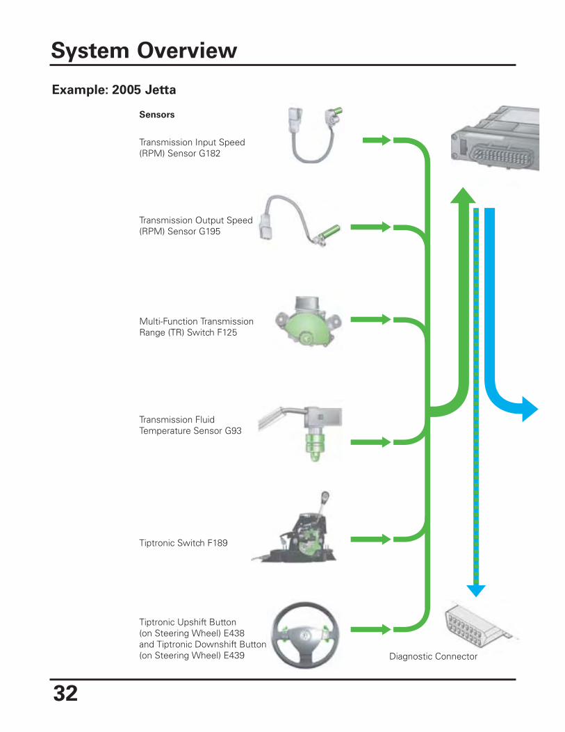
System Overview
Sensors
Transmission Input Speed(RPM) Sensor G182
Transmission Output Speed(RPM) Sensor G195
Multi-Function TransmissionRange (TR) Switch F125
Transmission FluidTemperature Sensor G93
Tiptronic Switch F189
Tiptronic Upshift Button(on Steering Wheel) E438and Tiptronic Downshift Button(on Steering Wheel) E439 Diagnostic Connector
Example: 2005 Jetta
33
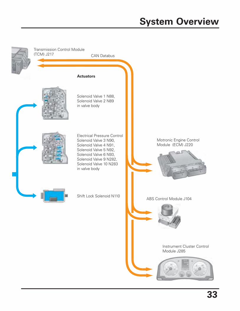
System Overview
Actuators
Transmission Control Module(TCM) J217
Solenoid Valve 1 N88,Solenoid Valve 2 N89in valve body
Shift Lock Solenoid N110
Motronic Engine ControlModule (ECM) J220
ABS Control Module J104
Instrument Cluster ControlModule J285
Electrical Pressure ControlSolenoid Valve 3 N90,Solenoid Valve 4 N91,Solenoid Valve 5 N92,Solenoid Valve 6 N93,Solenoid Valve 9 N282,Solenoid Valve 10 N283in valve body
CAN Databus
34
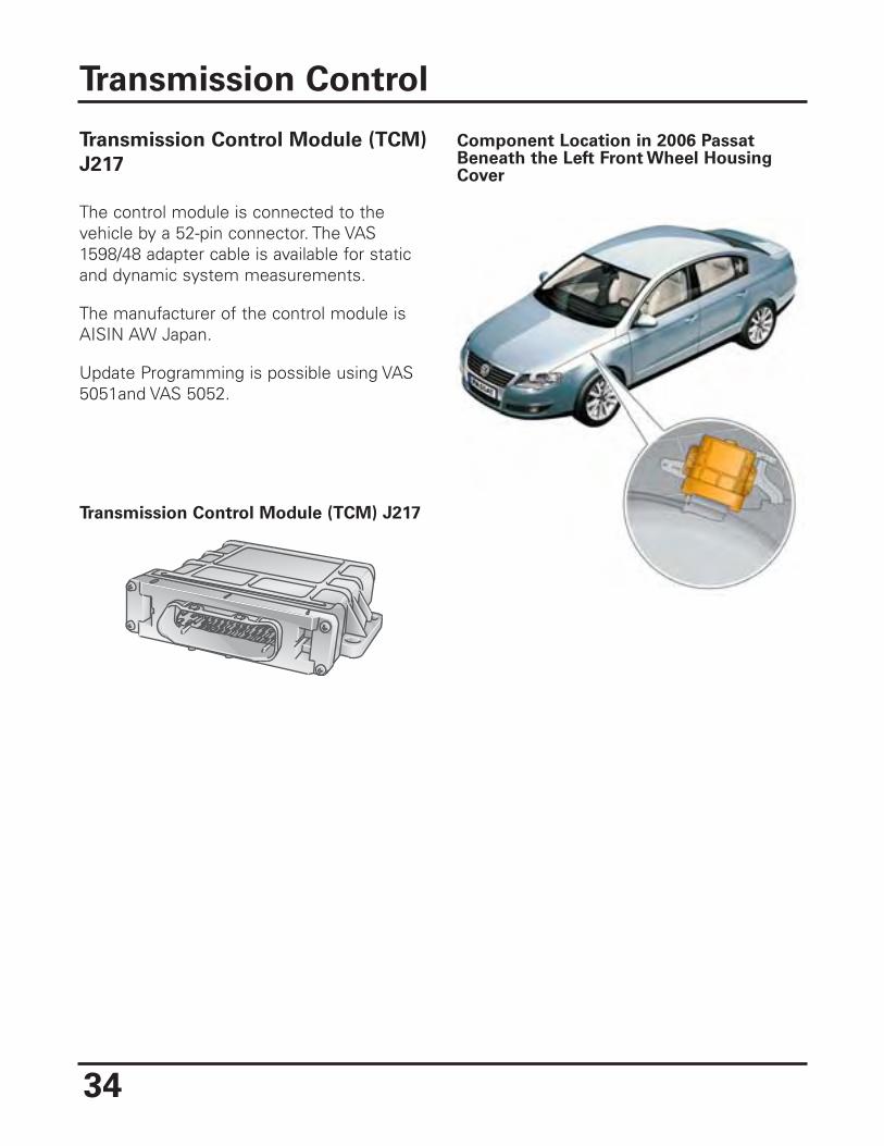
Transmission Control Module (TCM)
J217
The control module is connected to thevehicle by a 52-pin connector. The VAS1598/48 adapter cable is available for staticand dynamic system measurements.
The manufacturer of the control module isAISIN AW Japan.
Update Programming is possible using VAS5051and VAS 5052.
Transmission Control
Component Location in 2006 PassatBeneath the Left Front Wheel HousingCover
Transmission Control Module (TCM) J217
35
Dynamic Shifting Program DSP
This automatic transmission has the latestgeneration Dynamic Shifting Program DSP.
The driving conditions, as well as forexample the driving resistance (e.g.,climbing), the road profile (e.g., curve), andthe driver type (manner of driving) areevaluated.
The basic parameters for the calculation ofthe gear selection have not fundamentallychanged compared to previous automatictransmissions. Due to the constantlyincreasing integration of the transmissioncontrol with other vehicle systems, such asthe engine, ESP, or the steering anglesensor, a large amount of information isavailable to better define the current drivingconditions and the driving manner.
Sport Mode “S”
A performance-oriented shifting program isavailable to the driver in selector leverposition “S”.
If the Transmission Control Module (TCM)J217 recognizes the selector lever position“S”, the shifting characteristic curves arereallocated to higher engine speeds. Thisincreases the driving dynamic.
The DSP also adapts to driver input (drivertype evaluation) and driving situations in “S”position.
The “S” mode contains the followingcharacteristics:
• If the selector lever is placed in “S”while driving with an unchangingaccelerator pedal position, a downshiftoccurs within defined limits.
• To achieve a more direct driving reactionto the movements of the acceleratorpedal, the torque converter lock-upclutch closes as soon as possible.
If 6th gear is designed as the E-gear for theoverall transmission ratio, only gears 1through 5 are used.
Transmission Control
36
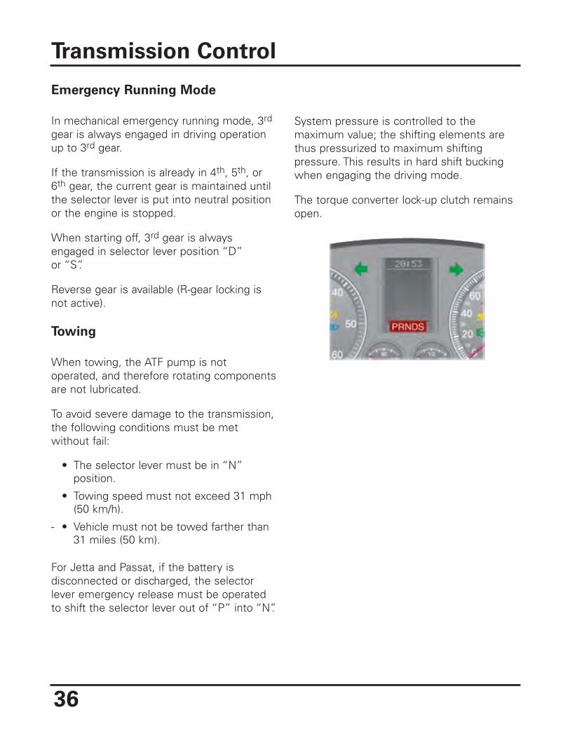
Emergency Running Mode
In mechanical emergency running mode, 3rd
gear is always engaged in driving operationup to 3rd gear.
If the transmission is already in 4th, 5th, or6th gear, the current gear is maintained untilthe selector lever is put into neutral positionor the engine is stopped.
When starting off, 3rd gear is alwaysengaged in selector lever position “D”or “S”.
Reverse gear is available (R-gear locking isnot active).
Towing
When towing, the ATF pump is notoperated, and therefore rotating componentsare not lubricated.
To avoid severe damage to the transmission,the following conditions must be metwithout fail:
• The selector lever must be in “N”position.
• Towing speed must not exceed 31 mph(50 km/h).
- • Vehicle must not be towed farther than31 miles (50 km).
For Jetta and Passat, if the battery isdisconnected or discharged, the selectorlever emergency release must be operatedto shift the selector lever out of “P” into “N”.
System pressure is controlled to themaximum value; the shifting elements arethus pressurized to maximum shiftingpressure. This results in hard shift buckingwhen engaging the driving mode.
The torque converter lock-up clutch remainsopen.
Transmission Control
37
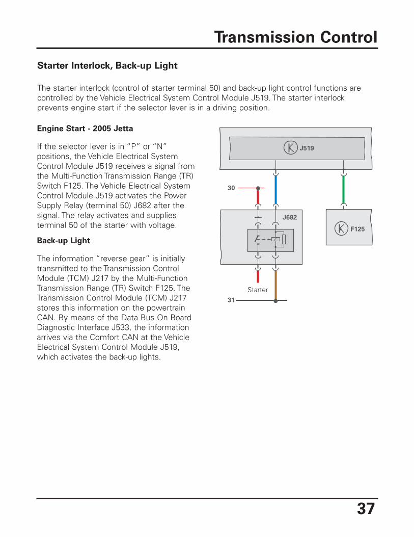
Starter Interlock, Back-up Light
The starter interlock (control of starter terminal 50) and back-up light control functions arecontrolled by the Vehicle Electrical System Control Module J519. The starter interlockprevents engine start if the selector lever is in a driving position.
Transmission Control
Engine Start - 2005 Jetta
If the selector lever is in “P” or “N”positions, the Vehicle Electrical SystemControl Module J519 receives a signal fromthe Multi-Function Transmission Range (TR)Switch F125. The Vehicle Electrical SystemControl Module J519 activates the PowerSupply Relay (terminal 50) J682 after thesignal. The relay activates and suppliesterminal 50 of the starter with voltage.
Back-up Light
The information “reverse gear” is initiallytransmitted to the Transmission ControlModule (TCM) J217 by the Multi-FunctionTransmission Range (TR) Switch F125. TheTransmission Control Module (TCM) J217stores this information on the powertrainCAN. By means of the Data Bus On BoardDiagnostic Interface J533, the informationarrives via the Comfort CAN at the VehicleElectrical System Control Module J519,which activates the back-up lights.
31
J519
J682
F125
30
Starter
38
Sensors
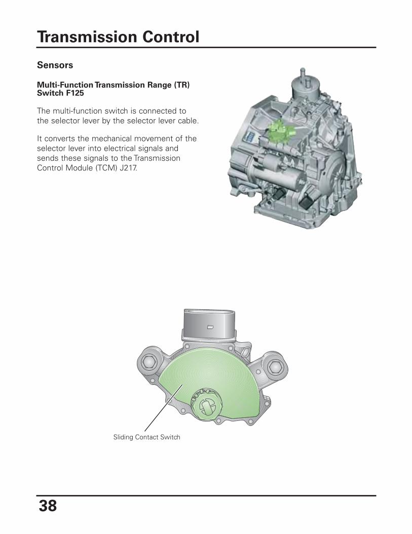
Multi-Function Transmission Range (TR)Switch F125
The multi-function switch is connected tothe selector lever by the selector lever cable.
It converts the mechanical movement of theselector lever into electrical signals andsends these signals to the TransmissionControl Module (TCM) J217.
Transmission Control
Sliding Contact Switch
39
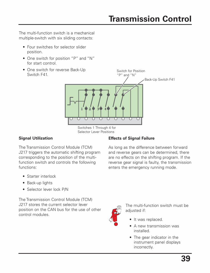
Switch for Position“P” and “N”
Back-Up Switch F41
Switches 1 Through 4 forSelector Lever Positions
The multi-function switch is a mechanicalmultiple-switch with six sliding contacts:
• Four switches for selector sliderposition.
• One switch for position “P” and “N”for start control.
• One switch for reverse Back-UpSwitch F41.
Effects of Signal Failure
As long as the difference between forwardand reverse gears can be determined, thereare no effects on the shifting program. If thereverse gear signal is faulty, the transmissionenters the emergency running mode.
Transmission Control
Signal Utilization
The Transmission Control Module (TCM)J217 triggers the automatic shifting programcorresponding to the position of the multi-function switch and controls the followingfunctions:
• Starter interlock
• Back-up lights
• Selector lever lock P/N
The Transmission Control Module (TCM)J217 stores the current selector leverposition on the CAN bus for the use of othercontrol modules.
The multi-function switch must beadjusted if:
• It was replaced.
• A new transmission wasinstalled.
• The gear indicator in theinstrument panel displaysincorrectly.
40
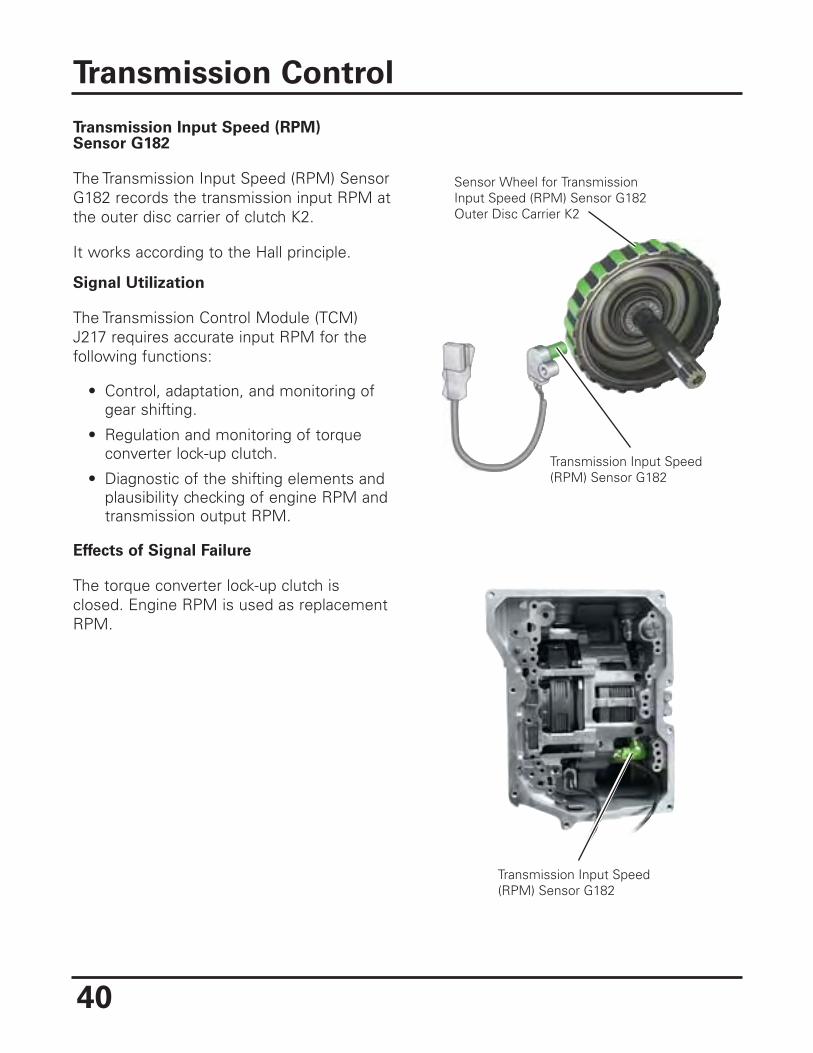
Transmission Input Speed (RPM)Sensor G182
The Transmission Input Speed (RPM) SensorG182 records the transmission input RPM atthe outer disc carrier of clutch K2.
It works according to the Hall principle.
Signal Utilization
The Transmission Control Module (TCM)J217 requires accurate input RPM for thefollowing functions:
• Control, adaptation, and monitoring ofgear shifting.
• Regulation and monitoring of torqueconverter lock-up clutch.
• Diagnostic of the shifting elements andplausibility checking of engine RPM andtransmission output RPM.
Effects of Signal Failure
The torque converter lock-up clutch isclosed. Engine RPM is used as replacementRPM.
Transmission Control
Transmission Input Speed(RPM) Sensor G182
Sensor Wheel for TransmissionInput Speed (RPM) Sensor G182Outer Disc Carrier K2
Transmission Input Speed(RPM) Sensor G182
41
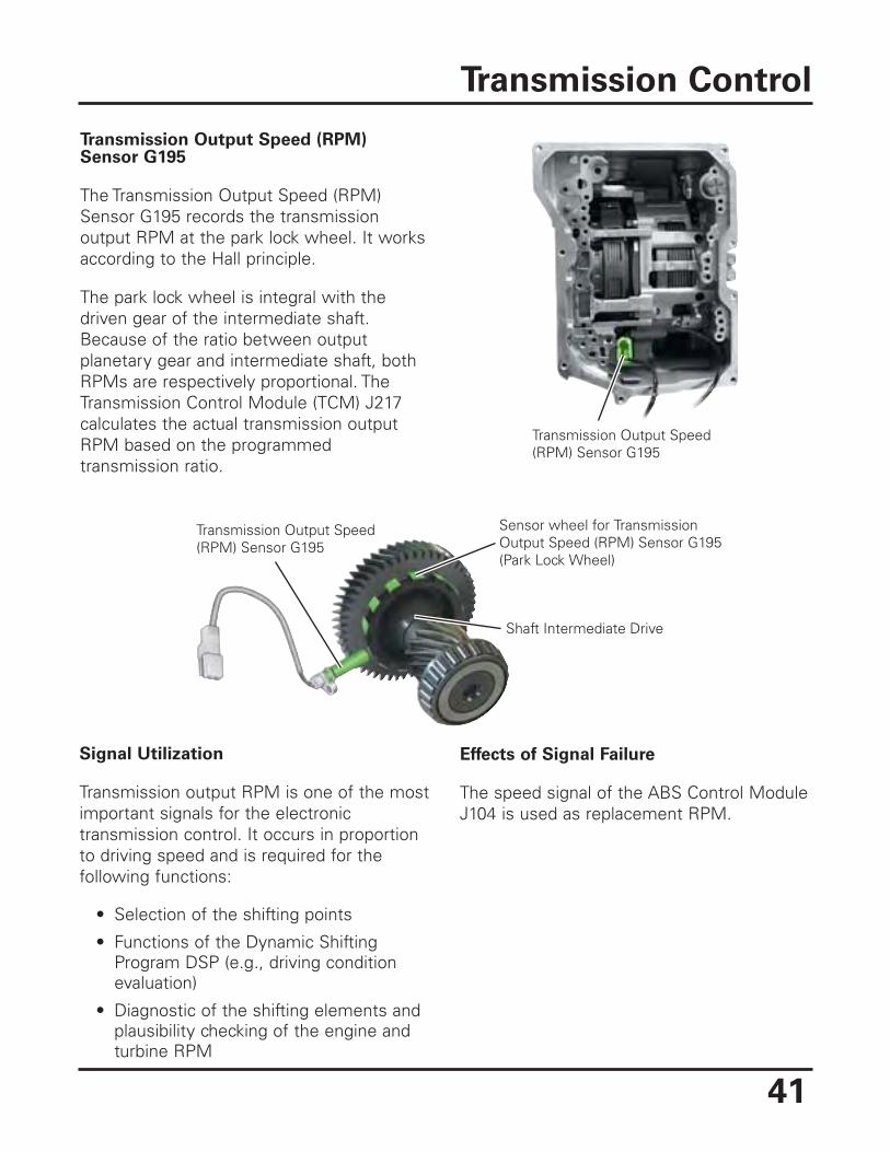
Transmission Output Speed (RPM)Sensor G195
The Transmission Output Speed (RPM)Sensor G195 records the transmissionoutput RPM at the park lock wheel. It worksaccording to the Hall principle.
The park lock wheel is integral with thedriven gear of the intermediate shaft.Because of the ratio between outputplanetary gear and intermediate shaft, bothRPMs are respectively proportional. TheTransmission Control Module (TCM) J217calculates the actual transmission outputRPM based on the programmedtransmission ratio.
Effects of Signal Failure
The speed signal of the ABS Control ModuleJ104 is used as replacement RPM.
Transmission Control
Signal Utilization
Transmission output RPM is one of the mostimportant signals for the electronictransmission control. It occurs in proportionto driving speed and is required for thefollowing functions:
• Selection of the shifting points
• Functions of the Dynamic ShiftingProgram DSP (e.g., driving conditionevaluation)
• Diagnostic of the shifting elements andplausibility checking of the engine andturbine RPM
Sensor wheel for TransmissionOutput Speed (RPM) Sensor G195(Park Lock Wheel)
Transmission Output Speed(RPM) Sensor G195
Shaft Intermediate Drive
Transmission Output Speed(RPM) Sensor G195
42
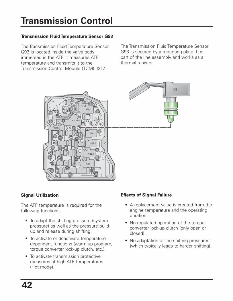
Transmission Fluid Temperature Sensor G93
The Transmission Fluid Temperature SensorG93 is located inside the valve bodyimmersed in the ATF. It measures ATFtemperature and transmits it to theTransmission Control Module (TCM) J217.
Effects of Signal Failure
• A replacement value is created from theengine temperature and the operatingduration.
• No regulated operation of the torqueconverter lock-up clutch (only open orclosed).
• No adaptation of the shifting pressures(which typically leads to harder shifting).
Transmission Control
N89
N88
N89
N92
N93
N91
N282
N283
N90
Signal Utilization
The ATF temperature is required for thefollowing functions:
• To adapt the shifting pressure (systempressure) as well as the pressure build-up and release during shifting.
• To activate or deactivate temperature-dependent functions (warm-up program,torque converter lock-up clutch, etc.).
• To activate transmission protectivemeasures at high ATF temperatures(Hot mode).
The Transmission Fluid Temperature SensorG93 is secured by a mounting plate. It ispart of the line assembly and works as athermal resistor.
43
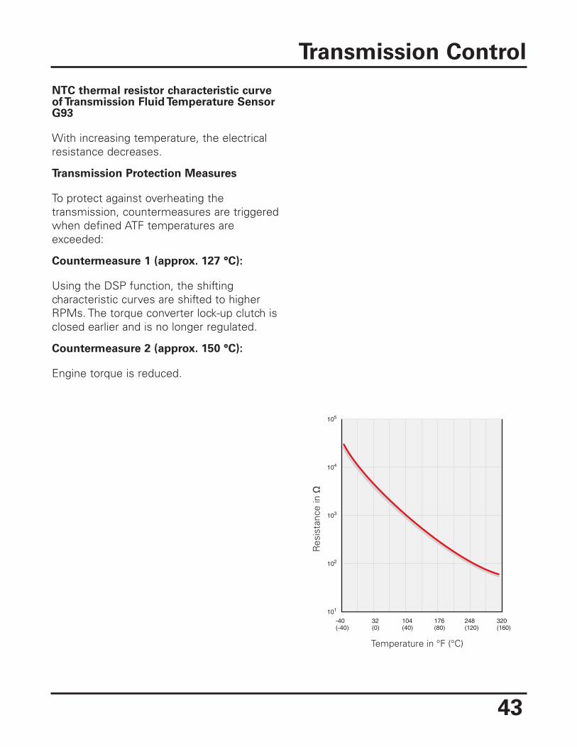
NTC thermal resistor characteristic curveof Transmission Fluid Temperature SensorG93
With increasing temperature, the electricalresistance decreases.
Transmission Protection Measures
To protect against overheating thetransmission, countermeasures are triggeredwhen defined ATF temperatures areexceeded:
Countermeasure 1 (approx. 127 °C):
Using the DSP function, the shiftingcharacteristic curves are shifted to higherRPMs. The torque converter lock-up clutch isclosed earlier and is no longer regulated.
Countermeasure 2 (approx. 150 °C):
Engine torque is reduced.
Transmission Control
104
105
32-40 176 248 320(40)(0)(-40) (80) (120) (160)
104
103
102
101
Temperature in °F (°C)
44
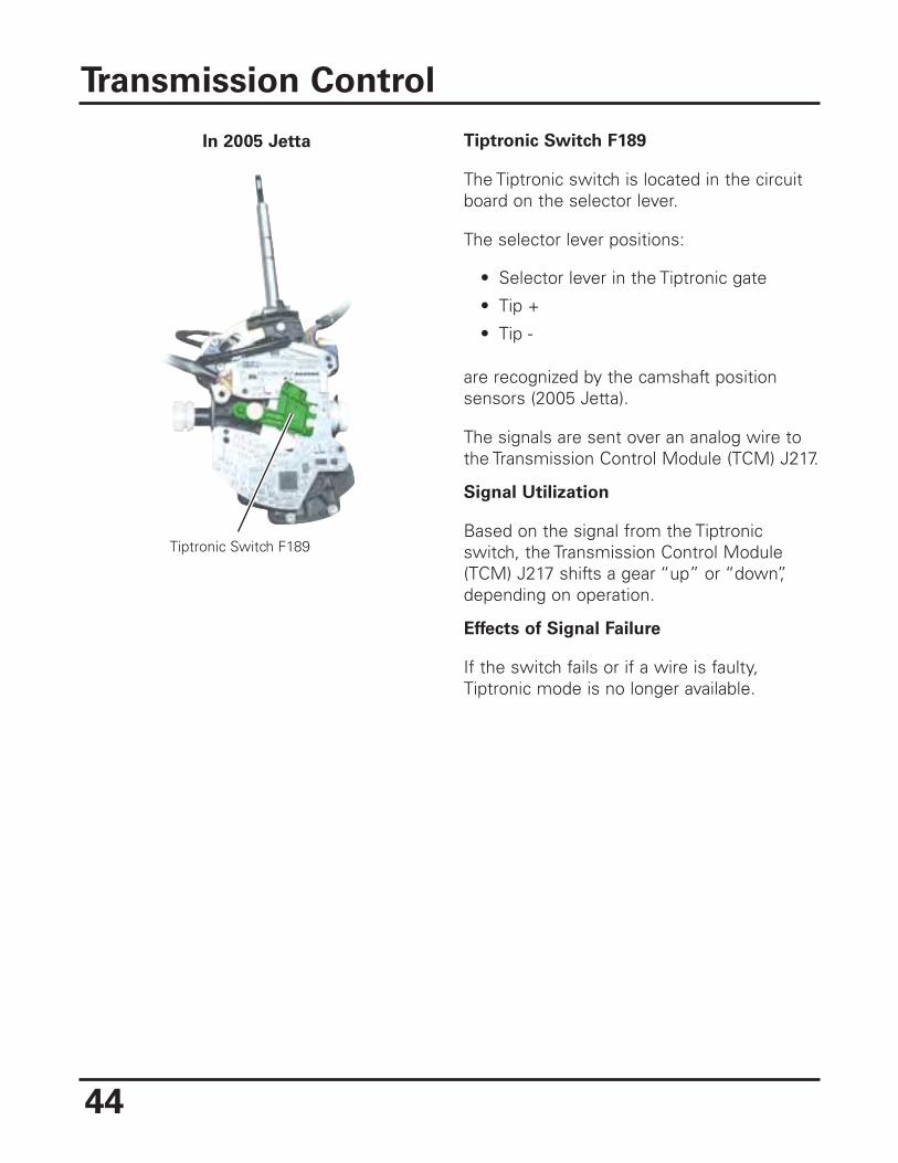
Tiptronic Switch F189
The Tiptronic switch is located in the circuitboard on the selector lever.
The selector lever positions:
• Selector lever in the Tiptronic gate
• Tip +
• Tip -
are recognized by the camshaft positionsensors (2005 Jetta).
The signals are sent over an analog wire tothe Transmission Control Module (TCM) J217.
Signal Utilization
Based on the signal from the Tiptronicswitch, the Transmission Control Module(TCM) J217 shifts a gear “up” or “down”,depending on operation.
Effects of Signal Failure
If the switch fails or if a wire is faulty,Tiptronic mode is no longer available.
Transmission Control
Tiptronic Switch F189
In 2005 Jetta
45
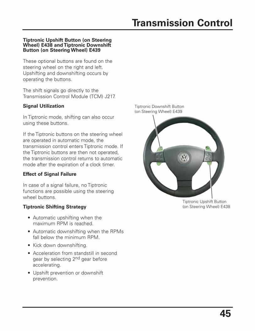
Tiptronic Upshift Button (on SteeringWheel) E438 and Tiptronic DownshiftButton (on Steering Wheel) E439
These optional buttons are found on thesteering wheel on the right and left.Upshifting and downshifting occurs byoperating the buttons.
The shift signals go directly to theTransmission Control Module (TCM) J217.
Signal Utilization
In Tiptronic mode, shifting can also occurusing these buttons.
If the Tiptronic buttons on the steering wheelare operated in automatic mode, thetransmission control enters Tiptronic mode. Ifthe Tiptronic buttons are then not operated,the transmission control returns to automaticmode after the expiration of a clock timer.
Effect of Signal Failure
In case of a signal failure, no Tiptronicfunctions are possible using the steeringwheel buttons.
Tiptronic Shifting Strategy
• Automatic upshifting when themaximum RPM is reached.
• Automatic downshifting when the RPMsfall below the minimum RPM.
• Kick down downshifting.
• Acceleration from standstill in secondgear by selecting 2nd gear beforeaccelerating.
• Upshift prevention or downshiftprevention.
Transmission Control
Tiptronic Downshift Button(on Steering Wheel) E439
Tiptronic Upshift Button(on Steering Wheel) E438
46
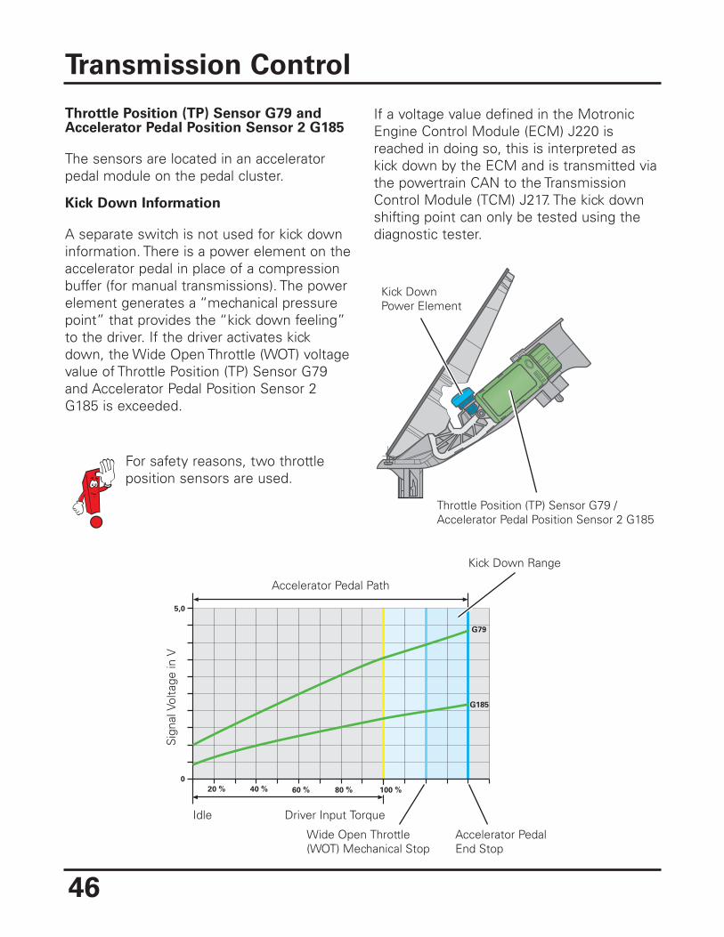
Throttle Position (TP) Sensor G79 andAccelerator Pedal Position Sensor 2 G185
The sensors are located in an acceleratorpedal module on the pedal cluster.
Kick Down Information
A separate switch is not used for kick downinformation. There is a power element on theaccelerator pedal in place of a compressionbuffer (for manual transmissions). The powerelement generates a “mechanical pressurepoint” that provides the “kick down feeling”to the driver. If the driver activates kickdown, the Wide Open Throttle (WOT) voltagevalue of Throttle Position (TP) Sensor G79and Accelerator Pedal Position Sensor 2G185 is exceeded.
If a voltage value defined in the MotronicEngine Control Module (ECM) J220 isreached in doing so, this is interpreted askick down by the ECM and is transmitted viathe powertrain CAN to the TransmissionControl Module (TCM) J217. The kick downshifting point can only be tested using thediagnostic tester.
Transmission Control
100 %
0
G79
G185
5,0
20 % 40 % 60 % 80 %
Sig
nal V
olta
ge in
V
Accelerator Pedal Path
Kick Down Range
Idle Driver Input Torque
Wide Open Throttle(WOT) Mechanical Stop
Accelerator PedalEnd Stop
Kick DownPower Element
Throttle Position (TP) Sensor G79 /Accelerator Pedal Position Sensor 2 G185
For safety reasons, two throttleposition sensors are used.
47
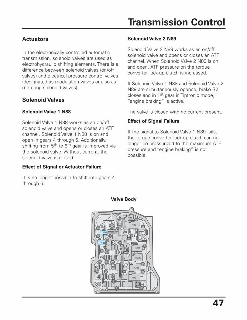
Actuators
In the electronically controlled automatictransmission, solenoid valves are used aselectrohydraulic shifting elements. There is adifference between solenoid valves (on/offvalves) and electrical pressure control valves(designated as modulation valves or also asmetering solenoid valves).
Solenoid Valves
Solenoid Valve 1 N88
Solenoid Valve 1 N88 works as an on/offsolenoid valve and opens or closes an ATFchannel. Solenoid Valve 1 N88 is on andopen in gears 4 through 6. Additionally,shifting from 5th to 6th gear is improved viathe solenoid valve. Without current, thesolenoid valve is closed.
Effect of Signal or Actuator Failure
It is no longer possible to shift into gears 4through 6.
Solenoid Valve 2 N89
Solenoid Valve 2 N89 works as an on/offsolenoid valve and opens or closes an ATFchannel. When Solenoid Valve 2 N89 is onand open, ATF pressure on the torqueconverter lock-up clutch is increased.
If Solenoid Valve 1 N88 and Solenoid Valve 2N89 are simultaneously opened, brake B2closes and in 1st gear in Tiptronic mode,“engine braking” is active.
The valve is closed with no current present.
Effect of Signal Failure
If the signal to Solenoid Valve 1 N89 fails,the torque converter lock-up clutch can nolonger be pressurized to the maximum ATFpressure and “engine braking” is notpossible.
Transmission Control
N89
N88
N89
N92
N93
N91
N282
N283
N90
Valve Body
48
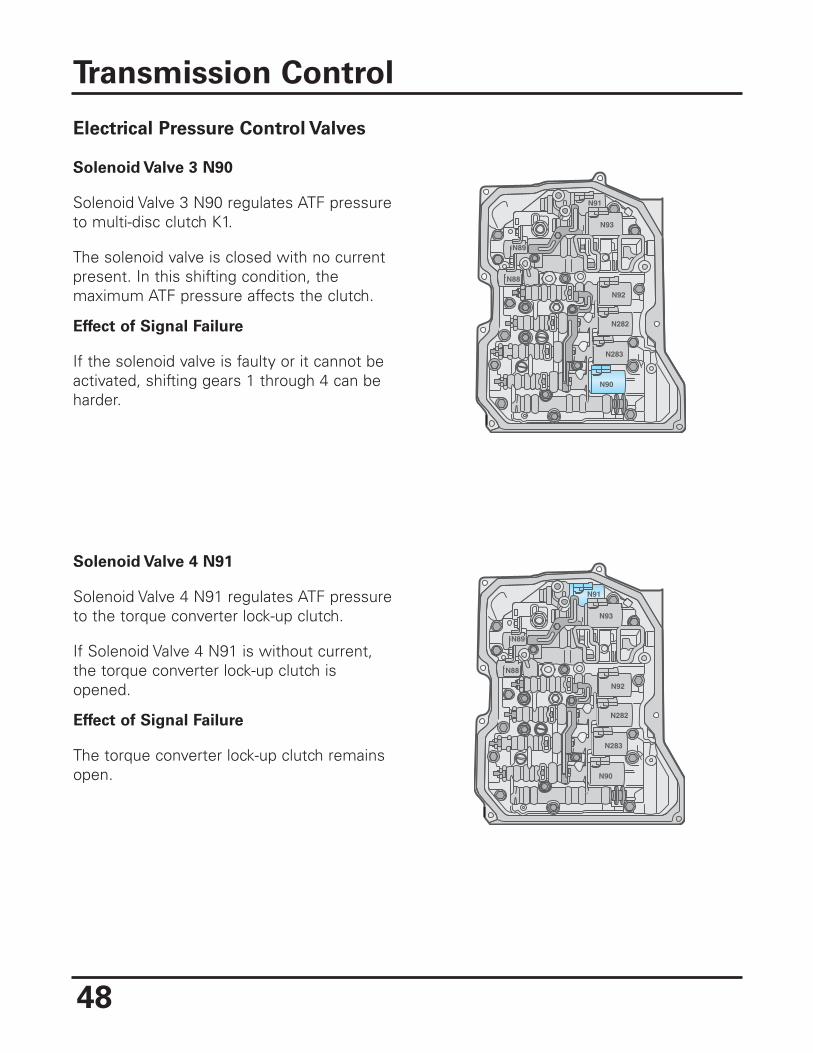
Electrical Pressure Control Valves
Solenoid Valve 3 N90
Solenoid Valve 3 N90 regulates ATF pressureto multi-disc clutch K1.
The solenoid valve is closed with no currentpresent. In this shifting condition, themaximum ATF pressure affects the clutch.
Effect of Signal Failure
If the solenoid valve is faulty or it cannot beactivated, shifting gears 1 through 4 can beharder.
Solenoid Valve 4 N91
Solenoid Valve 4 N91 regulates ATF pressureto the torque converter lock-up clutch.
If Solenoid Valve 4 N91 is without current,the torque converter lock-up clutch isopened.
Effect of Signal Failure
The torque converter lock-up clutch remainsopen.
Transmission Control
N89
N88
N89
N92
N93
N91
N282
N283
N90
N89
N88
N89
N92
N93
N91
N282
N283
N90
49
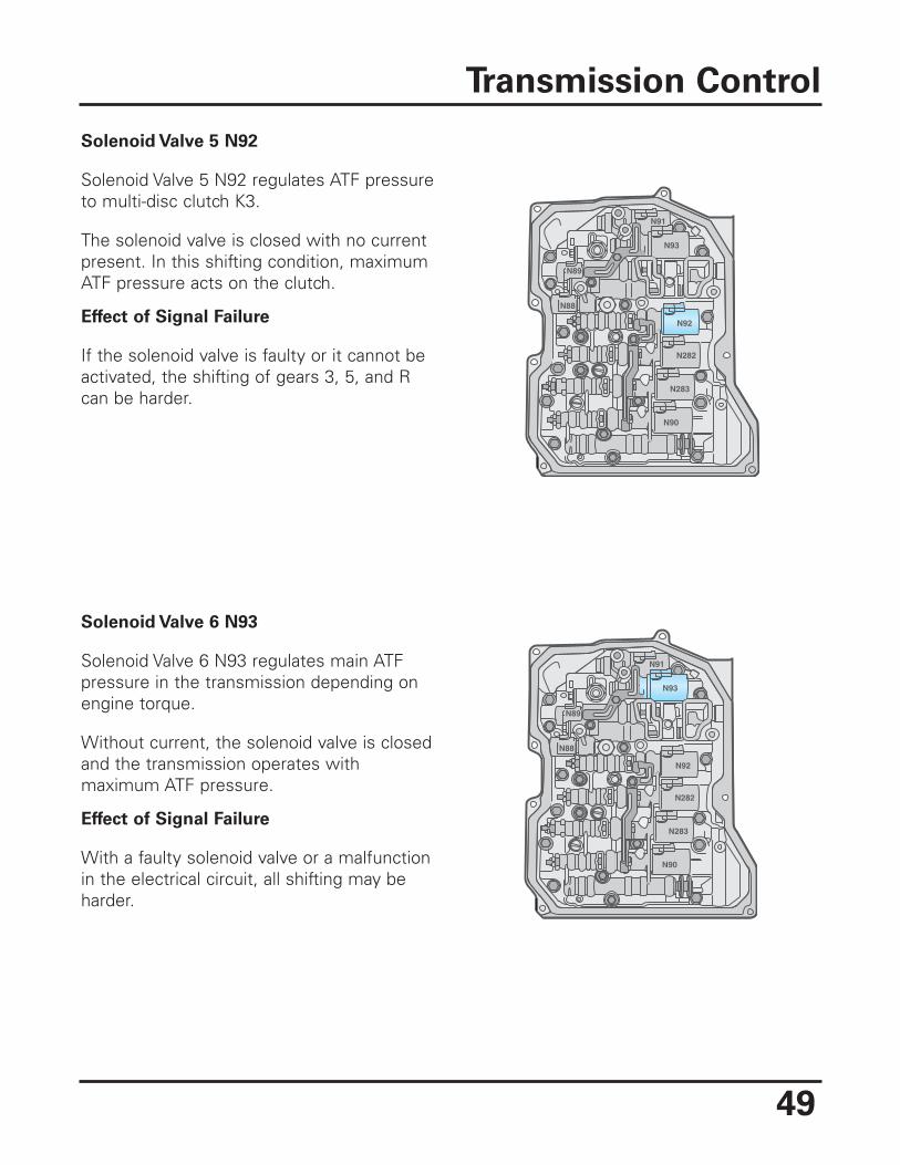
Solenoid Valve 5 N92
Solenoid Valve 5 N92 regulates ATF pressureto multi-disc clutch K3.
The solenoid valve is closed with no currentpresent. In this shifting condition, maximumATF pressure acts on the clutch.
Effect of Signal Failure
If the solenoid valve is faulty or it cannot beactivated, the shifting of gears 3, 5, and Rcan be harder.
Transmission Control
Solenoid Valve 6 N93
Solenoid Valve 6 N93 regulates main ATFpressure in the transmission depending onengine torque.
Without current, the solenoid valve is closedand the transmission operates withmaximum ATF pressure.
Effect of Signal Failure
With a faulty solenoid valve or a malfunctionin the electrical circuit, all shifting may beharder.
N89
N88
N89
N92
N93
N91
N282
N283
N90
N89
N88
N89
N92
N93
N91
N282
N283
N90
50
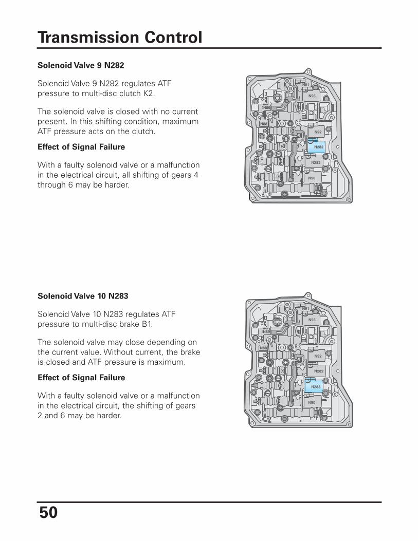
Solenoid Valve 9 N282
Solenoid Valve 9 N282 regulates ATFpressure to multi-disc clutch K2.
The solenoid valve is closed with no currentpresent. In this shifting condition, maximumATF pressure acts on the clutch.
Effect of Signal Failure
With a faulty solenoid valve or a malfunctionin the electrical circuit, all shifting of gears 4through 6 may be harder.
Transmission Control
Solenoid Valve 10 N283
Solenoid Valve 10 N283 regulates ATFpressure to multi-disc brake B1.
The solenoid valve may close depending onthe current value. Without current, the brakeis closed and ATF pressure is maximum.
Effect of Signal Failure
With a faulty solenoid valve or a malfunctionin the electrical circuit, the shifting of gears2 and 6 may be harder.
N89
N88
N89
N92
N93
N91
N282
N283
N90
N89
N88
N89
N92
N93
N91
N282
N283
N90
51
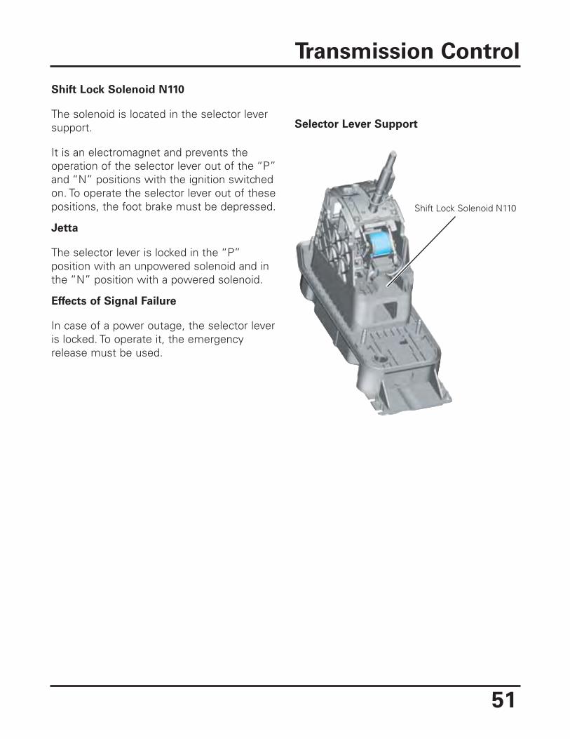
Shift Lock Solenoid N110
The solenoid is located in the selector leversupport.
It is an electromagnet and prevents theoperation of the selector lever out of the “P”and “N” positions with the ignition switchedon. To operate the selector lever out of thesepositions, the foot brake must be depressed.
Jetta
The selector lever is locked in the “P”position with an unpowered solenoid and inthe “N” position with a powered solenoid.
Effects of Signal Failure
In case of a power outage, the selector leveris locked. To operate it, the emergencyrelease must be used.
Transmission Control
Shift Lock Solenoid N110
Selector Lever Support
52
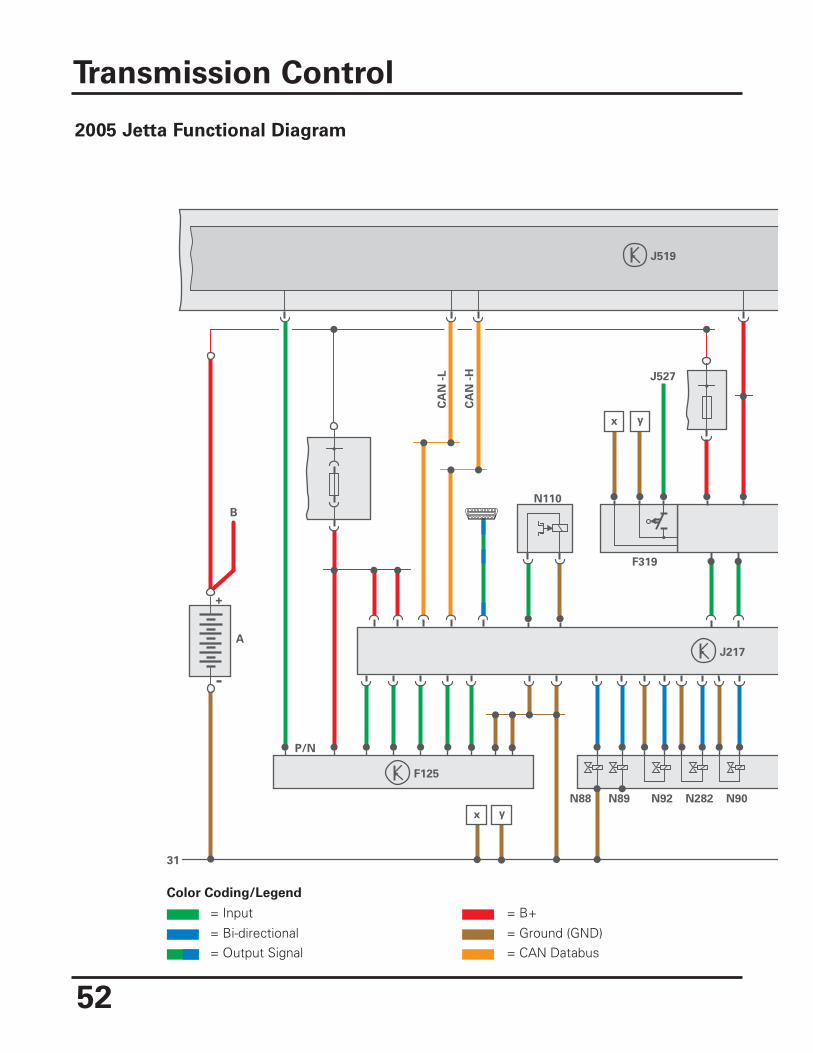
Transmission Control
B
31
J519
J217
N88
x y
N89 N92 N282 N90
yx
J527
F319
CA
N -
L
CA
N -
H
N110
F125
+
-
A
P/N
Color Coding/Legend
= Input
= Bi-directional= Output Signal
= B+
= Ground (GND)= CAN Databus
2005 Jetta Functional Diagram
53
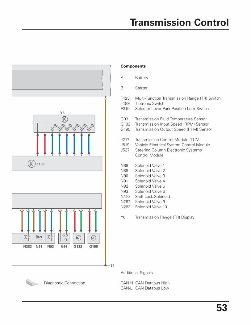
Transmission Control
31
F189
N283 N91 N93 G93 G182 G195
Y6
A Battery
B Starter
F125 Multi-Function Transmission Range (TR) SwitchF189 Tiptronic SwitchF319 Selector Lever Park Position Lock Switch
G93 Transmission Fluid Temperature SensorG182 Transmission Input Speed (RPM) SensorG195 Transmission Output Speed (RPM) Sensor
J217 Transmission Control Module (TCM)J519 Vehicle Electrical System Control ModuleJ527 Steering Column Electronic Systems Control Module
N88 Solenoid Valve 1N89 Solenoid Valve 2N90 Solenoid Valve 3N91 Solenoid Valve 4N92 Solenoid Valve 5N93 Solenoid Valve 6N110 Shift Lock SolenoidN282 Solenoid Valve 9N283 Solenoid Valve 10
Y6 Transmission Range (TR) Display
Components
Diagnostic Connection CAN-H CAN Databus HighCAN-L CAN Databus Low
Additional Signals
54
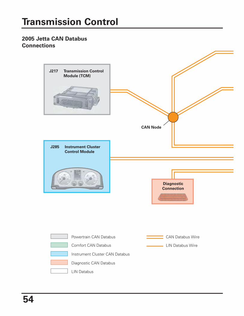
J217 Transmission Control
Module (TCM)
J285 Instrument Cluster
Control Module
CAN Node
Diagnostic
Connection
Powertrain CAN Databus CAN Databus Wire
LIN Databus WireComfort CAN Databus
Instrument Cluster CAN Databus
Diagnostic CAN Databus
LIN Databus
Transmission Control
2005 Jetta CAN Databus
Connections
55
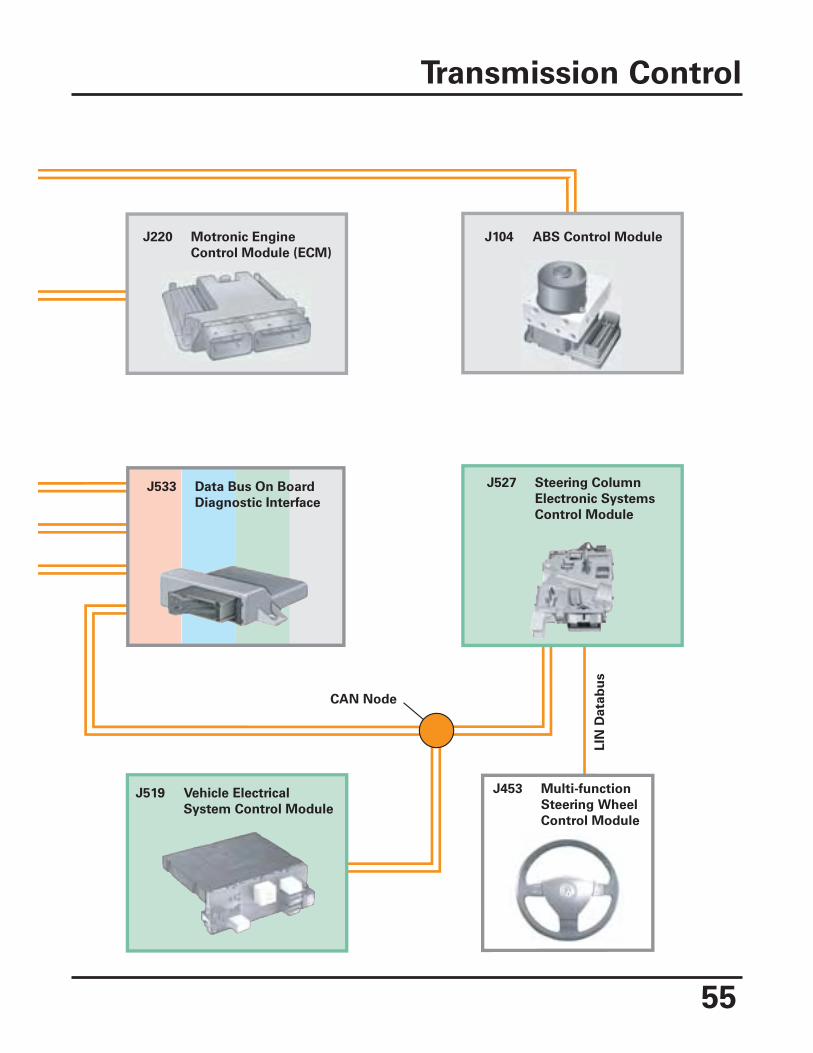
Transmission Control
J220 Motronic Engine
Control Module (ECM)
J533 Data Bus On Board
Diagnostic Interface
J519 Vehicle Electrical
System Control Module
J104 ABS Control Module
J527 Steering Column
Electronic Systems
Control Module
J453 Multi-function
Steering Wheel
Control Module
CAN Node
LIN
Da
tab
us
56
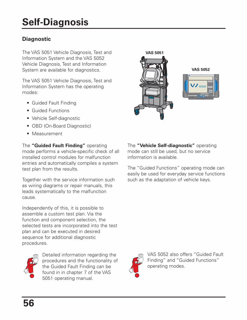
Diagnostic
The VAS 5051 Vehicle Diagnosis, Test andInformation System and the VAS 5052Vehicle Diagnosis, Test and InformationSystem are available for diagnostics.
The VAS 5051 Vehicle Diagnosis, Test andInformation System has the operatingmodes:
• Guided Fault Finding
• Guided Functions
• Vehicle Self-diagnostic
• OBD (On-Board Diagnostic)
• Measurement
The “Guided Fault Finding” operatingmode performs a vehicle-specific check of allinstalled control modules for malfunctionentries and automatically compiles a systemtest plan from the results.
Together with the service information suchas wiring diagrams or repair manuals, thisleads systematically to the malfunctioncause.
Independently of this, it is possible toassemble a custom test plan. Via thefunction and component selection, theselected tests are incorporated into the testplan and can be executed in desiredsequence for additional diagnosticprocedures.
The “Vehicle Self-diagnostic” operatingmode can still be used, but no serviceinformation is available.
The “Guided Functions” operating mode caneasily be used for everyday service functionssuch as the adaptation of vehicle keys.
Self-Diagnosis
IrDA + - VAS 5052
WORKSHOPEQUIPMENTWORKSHOPEQUIPMENT
VAS 5051
VAS 5052
VAS 5052 also offers “Guided FaultFinding” and “Guided Functions”operating modes.
Detailed information regarding theprocedures and the functionality ofthe Guided Fault Finding can befound in in chapter 7 of the VAS5051 operating manual.
57
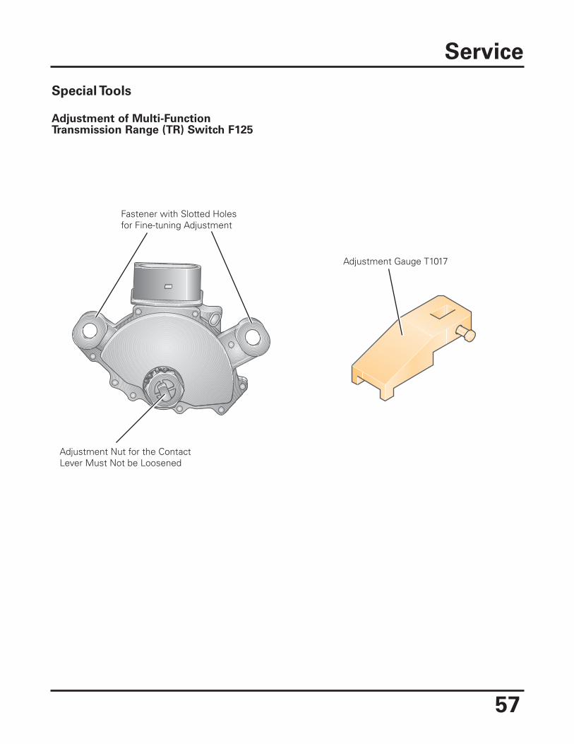
Special Tools
Adjustment of Multi-FunctionTransmission Range (TR) Switch F125
Service
Adjustment Nut for the ContactLever Must Not be Loosened
Fastener with Slotted Holesfor Fine-tuning Adjustment
Adjustment Gauge T1017
58
Terms
Spread In the context of transmissions as the subject under discussion, spread isdefined as the “gear ratio range” of a transmission. The spread is ratio betweenthe gear ratio in 1st gear and in 6th gear (highest gear). The value of the spreadis obtained by dividing the ratio of the 1st gear by that of the highest gear(here, 6th gear).
Using the 09G transmission as an example:
1st gear 4.148
6th gear 0.686 4.148 : 0.686 = 6.05 (value rounded up)
Advantages of a large spread are:
In addition to a high acceleration ratio (for high traction), a low end ratio can beachieved. This last provides for an RPM reduction, which in turn decreases thenoise level and enables a low fuel consumption.
A large spread requires a corresponding number of gears so that the RPMdifferences when shifting gears (gear transitions) are not too great. Whenshifting, the engine should not enter into low torque RPM ranges that wouldmake acceleration difficult or impossible.
TiptronicShiftingStrategy Acceleration from standstill occurs normally in 1st gear.
It is possible to accelerate from standstill in second gear by upshifting intosecond gear before accelerating (using steering wheel Tiptronic or selectorlever). This facilitates acceleration from standstill when road traction is low,e.g., for winter street conditions.
In addition to allowing the manual shifting of gears, the Tiptronic function isnecessary, for example, to make use of engine braking. By dispensing withpositions 4, 3, 2 (new selector lever shift gate with positions “D” and “S”), adesired upshift prevention must be selected using the Tiptronic function (shiftselector lever into the Tiptronic gate).
Glossary

An on-line Knowledge Assessment (exam) is available for this Self-Study Program
You can find this Knowledge Assessment on your Certification Resource Center
at:
www.vwwebsource.com
From the vwwebsource.com homepage, do the following:
1. Click on the Certification tab 2. Click on “My Certification” tab 3. Click the Fulfill link next to this SSP 4. Click “Launch Assessment”
For assistance, please call:
Volkswagen Academy Concierge 1 – 877 – 791 – 4838
(8:00 a.m. to 8:00 p.m. EST) Or, E-Mail:


Volkswagen of America, Inc.3800 Hamlin RoadAuburn Hills, MI 48326Printed in U.S.A.April 2005