Embed Size (px)
Citation preview

Page 1
© 2013. Siemens Product Lifecycle Management Software Inc. All rights reserved
Siemens PLM Software
1. Introduction to Laminate Composite Simulation
2. Zone-Based Process
3. Ply-Based Process
4. Modeling 3D Laminates
5. Materials and Micromechanics
6. Solution and Post-Processing
7. Laminate Theory
8. Laminate Failure Analysis
9. Laminate Dynamic Simulation
10. Laminate Optimization
Activities:
• Structural Analysis of Thick
Laminated Support
• Post reporting using mudguard
solution
Lesson 6

Page 2
© 2013. Siemens Product Lifecycle Management Software Inc. All rights reserved
Siemens PLM Software
Nastran solver properties- Laminate
You can export the 2D laminate as a PCOMP, PCOMPG, or PSHELL card.
Exported as NSM on the PCOMP, PCOMPG, or PSHELL cards.
If selected, SOUT is exported as YES on the PCOMP or PCOMPG card
Exported as GE on the PCOMP or PCOMPG cards.
Provide special purpose stiffness calculation for PCOMP and PCOMPG cards.

Page 3
© 2013. Siemens Product Lifecycle Management Software Inc. All rights reserved
Siemens PLM Software
Nastran solver properties -Laminate

Page 4
© 2013. Siemens Product Lifecycle Management Software Inc. All rights reserved
Siemens PLM Software
Nastran solver properties - Laminate

Page 5
© 2013. Siemens Product Lifecycle Management Software Inc. All rights reserved
Siemens PLM Software
What’s the Difference between PCOMP and PCOMPG?
Ply 100
Ply 103
Ply 101
4 ply global layup

Page 6
© 2013. Siemens Product Lifecycle Management Software Inc. All rights reserved
Siemens PLM Software
Ply Stresses - PCOMPG
Ply 100
Ply 103
Ply 101

Page 7
© 2013. Siemens Product Lifecycle Management Software Inc. All rights reserved
Siemens PLM Software
Ply Stresses - PCOMP
Ply 1
Ply 4
Ply 2

Page 8
© 2013. Siemens Product Lifecycle Management Software Inc. All rights reserved
Siemens PLM Software
Nastran solver properties - Laminate
Nastran internally converts the PCOMP and PCOMPG cards, along with the
associated material cards, to an equivalent PSHELL card with up to 4 anisotropic
MAT2 material cards.
Each MAT2 card represents a different behavior, depending on the PSHELL MID
that references it:
• MID1: Membrane
• MID2: Bending
• MID3: Transverse Shear
• MID4: Membrane-bending Coupling

Page 9
© 2013. Siemens Product Lifecycle Management Software Inc. All rights reserved
Siemens PLM Software
Nastran laminate export options for PCOMP , PCOMPG and PSHELL cards
Laminate Option NASTRAN Definition
None with Symmetric
stacking recipe
Only plies on one side of the mid plane are specified on the PCOMP card.
Does not apply for the PCOMPG card.
None with other
stacking recipes
All the plies are specified on the PCOMP or PCOMPG cards.
MEM Only membrane terms are retained. Intended for SOL 200.
BEND Only bending terms are retained. Intended for SOL 200.
SMEAR Stacking sequence is ignored, shear and bending-membrane coupling terms
are set to 0. Intended for SOL 200.
SMCORE with
Symmetric with Core
Stacking sequence is ignored, shear and bending-membrane coupling terms
are set to 0. Intended for SOL 200.
SMCORE + transverse
shear with Symmetric
with Core
For a sandwich, provides a PSHELL equivalent that includes membrane,
bending and transverse shear stiffness for which the extreme fiber stresses
(top of top ply and bottom of bottom ply) will be accurate. For all solutions.

Page 10
© 2013. Siemens Product Lifecycle Management Software Inc. All rights reserved
SMCORE + Transverse Shear
PSHELL representation of symmetric sandwich that allows for accurate recovery
of maximum and minimum isotropic facesheet stresses
Includes the following stiffness components:
• Membrane
• Bending (smeared facesheet representation)
• Transverse Shear
The simple PSHELL representation will not provide accurate stresses

Page 11
© 2013. Siemens Product Lifecycle Management Software Inc. All rights reserved
SMCORE + Transverse Shear - Max Stresses at –Z0 (Bottom of Ply 1)
PCOMP PSHELL
SMCORE+Tranverse Shear

Page 12
© 2013. Siemens Product Lifecycle Management Software Inc. All rights reserved
Siemens PLM Software
Nastran solver properties - Laminate Output Request SOUT • For the 2D laminate property, SOUT specifies whether or not the results are
written as text to the .f06 file.
• The results are always written to the .op2 file.

Page 16
© 2013. Siemens Product Lifecycle Management Software Inc. All rights reserved
Siemens PLM Software
Nastran solver properties- Solid Laminate
You can export the 3D laminate as a PCOMPS or a homogeneous PSOLID card.
If selected, SOUT is exported as YES on the PCOMPS card
Exported as GE on the PCOMPS card.

Page 17
© 2013. Siemens Product Lifecycle Management Software Inc. All rights reserved
Siemens PLM Software
Nastran solver properties – Solid Laminate Output Request SOUT • For the 3D solid laminate property, SOUT specifies whether or not the results
are written to the op2 file.
• Different behavior than for 2D laminates
• If you want results in NX Post, you must check this option.
• It is checked by default in the solid laminate modeler dialog.

Page 18
© 2013. Siemens Product Lifecycle Management Software Inc. All rights reserved
Siemens PLM Software
NX Nastran solver properties – Solid Laminate

Page 19
© 2013. Siemens Product Lifecycle Management Software Inc. All rights reserved
Siemens PLM Software
NX Nastran solver properties -– Solid Laminate

Page 20
© 2013. Siemens Product Lifecycle Management Software Inc. All rights reserved
Homogeneous Properties for 3D Laminates
Selectively replace PCOMPS by PSOLID
At the laminate/layup level
At the individual ply level
Benefit: faster solution time, fewer results
Equivalent 3D orthotropic material properties
are computed on-the-fly
Valid for symmetric and balanced layups
The further away the layup is from this
condition, the poorer the homogeneous
representation will be.
Works for NX Nastran, ANSYS and ABAQUS

Page 21
© 2013. Siemens Product Lifecycle Management Software Inc. All rights reserved
Siemens PLM Software
Nastran laminate results
Output Request
Force
Stress/Strain
Output Format PCOMP / PCOMPG/ PSHELL PSOLID/PCOMPS (NX) PCOMP / PCOMPG
PCOMP / PCOMPG/
PSHELL/PSOLID
PCOMPS (NX only)
Output Result Shell stress resultants Solid element forces Ply stresses and strains Ply and bond failure indices Ply and bond strength ratios Element stresses Element strains Ply stresses and strains Failure indices Strength ratios

Page 22
© 2013. Siemens Product Lifecycle Management Software Inc. All rights reserved
Nastran solutions that support ply results
• Linear statics 101
• Normal modes 103
• Buckling 105
• Nonlinear 1061
• Direct transient response 109
• Modal transient response 112
• Cyclic statics 114
• Nonlinear transient response 1291
• Design optimization 200
• Advanced nonlinear 601
Note
1. Not available for large displacement analysis

Page 23
© 2013. Siemens Product Lifecycle Management Software Inc. All rights reserved
Siemens PLM Software
NX Post – Native coordinate system
Native Coordinate System • Native means that the result in the op2, rst, fil or odb file is presented by
NX Post without transformation of the solver result.

Page 24
© 2013. Siemens Product Lifecycle Management Software Inc. All rights reserved
Siemens PLM Software
Nastran laminate results
Results Coordinate Systems in NX Post
• By default, shell stress resultants are displayed in the native (element)
coordinate system.
• DMAP can be used to force storage in the material system
• Ply stress and ply strain results are displayed in the native (ply)
coordinate system.
• Interlaminar ply stress and strain results are displayed in the:
• Native (material) coordinate system for 2D elements.
• Hence the core ribbon direction should be the material direction!
• Native (ply) coordinate system for 3D elements.

Page 25
© 2013. Siemens Product Lifecycle Management Software Inc. All rights reserved
Siemens PLM Software
Nastran laminate results
Results Locations in NX Post
• Ply results are at:
• The middle of the ply for 2D elements
• Where selected, for 3D elements
• Interlaminar results are at:
• The top of the ply for 2D elements
• The top and bottom of the ply (as requested) for 3D elements

Page 26
© 2013. Siemens Product Lifecycle Management Software Inc. All rights reserved
Siemens PLM Software
Nastran laminate results
Elemental/Nodal Output in NX Post
• 2D element ply results are at the element centroid only.
• Elemental in NX Post
• 3D element results are as selected
• Elemental in NX Post
• Element-Nodal in NX Post

Page 27
© 2013. Siemens Product Lifecycle Management Software Inc. All rights reserved
Siemens PLM Software
Nastran laminate results
Strength Ratios • To turn on the computation of Nastran strength ratios, you must edit
your solution and add the following PARAM:

Page 30
© 2013. Siemens Product Lifecycle Management Software Inc. All rights reserved
Siemens PLM Software
Shell stress resultant notations
NX Laminate Composites
Nx
Ny
Nxy
Mx (-Mx wrt Nastran)
My (-My wrt Nastran)
Mxy (-Mxy wrt Nastran)
Qx
Qy
Nastran
Fx
Fy
Fxy Mx My Mxy Vx
Vy
ABAQUS SF1 SF2 SF3 SM1 SM2 SM3 SF5 SF4
ANSYS
N11
N22
N12 M11 M22 M12 Q13
Q23
NX Post Processing
Nxx
Nyy
Nxy Mxx Myy Mxy Qxz
Qyz

Page 31
© 2013. Siemens Product Lifecycle Management Software Inc. All rights reserved
Siemens PLM Software
Nastran shell stress resultant convention The Nastran convention, shown in the following graphics, differs from the convention used by NX Laminate Composites in that the signs of the moments per
unit length Mx, My, and Mxy are reversed.
Nastran force convention Nastran moment convention

Page 32
© 2013. Siemens Product Lifecycle Management Software Inc. All rights reserved
Siemens PLM Software
Activity: Structural analysis of a thick laminated support
In this activity, you will:
•
• •
Create a laminate physical property.
Use the Extrude Laminate
command to inflate a 2D mesh with a laminate physical property definition.
Solve and display results in the post-
processing navigator
Page 33
© 2013. Siemens Product Lifecycle Management Software Inc. All rights reserved
Siemens PLM Software
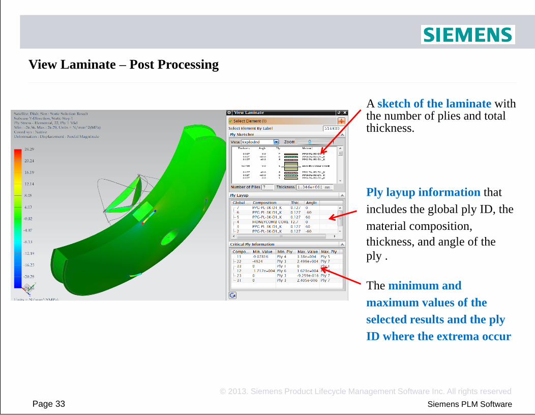
View Laminate – Post Processing
A sketch of the laminate with the number of plies and total thickness.
Ply layup information that
includes the global ply ID, the
material composition,
thickness, and angle of the
ply .
The minimum and
maximum values of the
selected results and the ply
ID where the extrema occur

Page 34
© 2013. Siemens Product Lifecycle Management Software Inc. All rights reserved
Siemens PLM Software
NXLC Advanced post reporting of laminate results Use the Advanced Post Report command to quickly identify critical element and ply data over many solutions. The enveloping, filtering, and sorting tools help you to find the critical element and ply data that you want without reviewing all the solver ply data. The command reads results from Nastran, ANSYS, or Abaqus, and computes: • Ply stresses and strains (2D)
• Ply and bond failure indices
• Ply and bond margins of safety
• Ply and bond strength ratios

Page 35
© 2013. Siemens Product Lifecycle Management Software Inc. All rights reserved
Siemens PLM Software
Laminate post reporting reads the shell stress resultants from the structural Solver, calculates ply stresses and strains and failure indices, strength ratios and margins of safety Laminate post reporting reads ply stresses and strains from the structural
2D results from solvers and laminate post reporting
solver and calculates failure indices, strength ratios and margins of safety
Solution
Shell Stress Resultants
Ply Stresses
Ply Strains
Ply failure indices &
strength ratios
So
lver
Ply Stresses
Ply Strains
Ply failure indices,
strength ratios &
margins of safety
NX
LC
Post R
epo
rting

Page 36
© 2013. Siemens Product Lifecycle Management Software Inc. All rights reserved
Siemens PLM Software
3D results from solvers and laminate post reporting
Laminate post reporting reads ply stresses and strains from the structural solver and calculates failure indices, strength ratios and margins of safety
Solution
Ply Stresses
Ply Strains
Ply failure indices &
strength ratios
So
lver
Ply failure indices,
strength ratios &
margins of safety
NX
LC
Po
st
Rep
ortin
g

Page 37
© 2013. Siemens Product Lifecycle Management Software Inc. All rights reserved
Siemens PLM Software
Advanced post processing of laminate results
Spreadsheet and graphical post reports use the laminate properties in your active FEM. • This allows you to switch failure theories or even modify your laminates after the solution was solved to perform what-if analyses without re-solving.
• It also allows you to validate your laminates using failure theories that are not
supported by the solver, including user-defined failure theories
• Post report currently computes elemental results only. NX automatically updates draping and zones if required, prior to accessing results. The quick post report queries the results without accessing the FEM.

Page 38
© 2013. Siemens Product Lifecycle Management Software Inc. All rights reserved
Siemens PLM Software
Laminate spreadsheet report The laminate spreadsheet report contains reports on the following laminate results: •
•
•
The shell stress resultants.
The specific components of ply stress and strain results.
The failure indices, strength ratios, and margins of safety.
You can output filtered and sorted ply results in laminate spreadsheet reports.

Page 39
© 2013. Siemens Product Lifecycle Management Software Inc. All rights reserved
Siemens PLM Software
Laminate spreadsheet summary tables The spreadsheet that is generated by the spreadsheet report or the quick report contains:
•
•
A top summary table that lists the worst ply values for all the result sets and structural data input selection.
A summary table for each result set and for each structural data input selection.
For each of the requested results, the summary tables display:
•
•
•
The location where the critical value occurs.
The critical value in blue.
The value of the other quantities at the same location.

Page 40
© 2013. Siemens Product Lifecycle Management Software Inc. All rights reserved
Siemens PLM Software
Laminate spreadsheet summary tables
Element
Layer/Ply
Location
Name of
laminate ppt
Failure
theory -
ply
Failure
theory - bond
Selected results &
components

Page 41
© 2013. Siemens Product Lifecycle Management Software Inc. All rights reserved
Siemens PLM Software
Laminate graphical report The laminate graphical report generates laminate results contours that you can display from the Post Processing Navigator. These results are stored in a binary file in the current directory. The laminate graphical report outputs the following laminate results:
• Ply stress and strain.
• Ply failure indices, strength ratios, and margins of safety.

Page 42
© 2013. Siemens Product Lifecycle Management Software Inc. All rights reserved
Siemens PLM Software
Laminate graphical report
Results are first enveloped over solutions, and then over all selected plies
Ply results
enveloped over all
solutions
Elemental results
enveloped over all
solutions and
over all plies

Page 43
© 2013. Siemens Product Lifecycle Management Software Inc. All rights reserved
Siemens PLM Software
Use the Show Critical Ply ID option of Post View to display the ID of the critical ply for the elemental, ply-enveloped results.
Laminate graphical report

Page 44
© 2013. Siemens Product Lifecycle Management Software Inc. All rights reserved
Siemens PLM Software
Use the Show Critical Load Case option of Post View to display the ID of the critical load case for the elemental, ply-enveloped results.
Laminate graphical report

Page 45
© 2013. Siemens Product Lifecycle Management Software Inc. All rights reserved
Siemens PLM Software
Results Source
• You can set the solver shell stress resultants or the solver ply stresses and
strains as the input to the laminate solver.
Results Location
• When using the shell stress resultants as the input, you can select any
combination of bottom, middle, and top locations for the ply stress/strain
calculation.
Results Coordinate System
• Results can be computed in the ply or the laminate coordinate systems.
• The laminate coordinate system option can only be used when the results source
is shell stress resultants.
Laminate graphical /spreadsheet reports

Page 46
© 2013. Siemens Product Lifecycle Management Software Inc. All rights reserved
Siemens PLM Software
Laminate graphical /spreadsheet reports
Computation Domain • You can also request the data on selected elements
and plies.

Page 47
© 2013. Siemens Product Lifecycle Management Software Inc. All rights reserved
Siemens PLM Software
Laminate quick report The laminate quick report exports the results summaries to an Excel spreadsheet or a CSV file without querying the active FEM. The quick report contains:
• •
A top summary table that lists the worst ply values for all the result sets. A summary table for each result set.

Page 48
© 2013. Siemens Product Lifecycle Management Software Inc. All rights reserved
Siemens PLM Software
NX Post Results Manipulation The NX Post results manipulation tools are capable of processing ply results

Page 49
© 2013. Siemens Product Lifecycle Management Software Inc. All rights reserved
Siemens PLM Software
Activity: Structural analysis of a satellite antenna
In this activity, you will:
• Create a simulation file with a Nastran or ANSYS solution.
• Use the View Laminate command
• Export ply results to a spreadsheet and a quick report.
• Create a graphical post report and identify the critical plies

Page 50
© 2013. Siemens Product Lifecycle Management Software Inc. All rights reserved
Siemens PLM Software
Review questions
1.
2.
3.
True/False. NX Laminate Composites can post process the results from Nastran, Abaqus, ANSYS, and LS-DYNA.
True/False. Spreadsheet and graphical post reports query the active FEM.
True/False. Spreadsheet and graphical post reports can filter and sort results.

Page 51
© 2013. Siemens Product Lifecycle Management Software Inc. All rights reserved
Siemens PLM Software
Answers to review questions
1. True/False. NX Laminate Composites can post process the results from Nastran, Abaqus, ANSYS, and LS-DYNA.
• False. You can only write out the LS-DYNA solver input file. NX does not support LS-DYNA solver and cannot post process LS-DYNA results.
2. True/False. Spreadsheet and graphical post reports query the active FEM.
• True. Spreadsheet and graphical post reports use the laminate properties in your active FEM, so that you can switch failure theories and even modify your laminates after the solution was solved to perform what-if analyses. The laminate quick report exports the results summaries to an Excel spreadsheet or a CSV file without querying the active FEM.
3. True/False. Spreadsheet and graphical post reports can filter and sort results.
• False. You can sort and filter the laminate results only with the spreadsheet report.