Embed Size (px)
Citation preview
TYPE 28 DRY-RUNNING, NON-CONTACTING GAS SEALS
Technical Specification
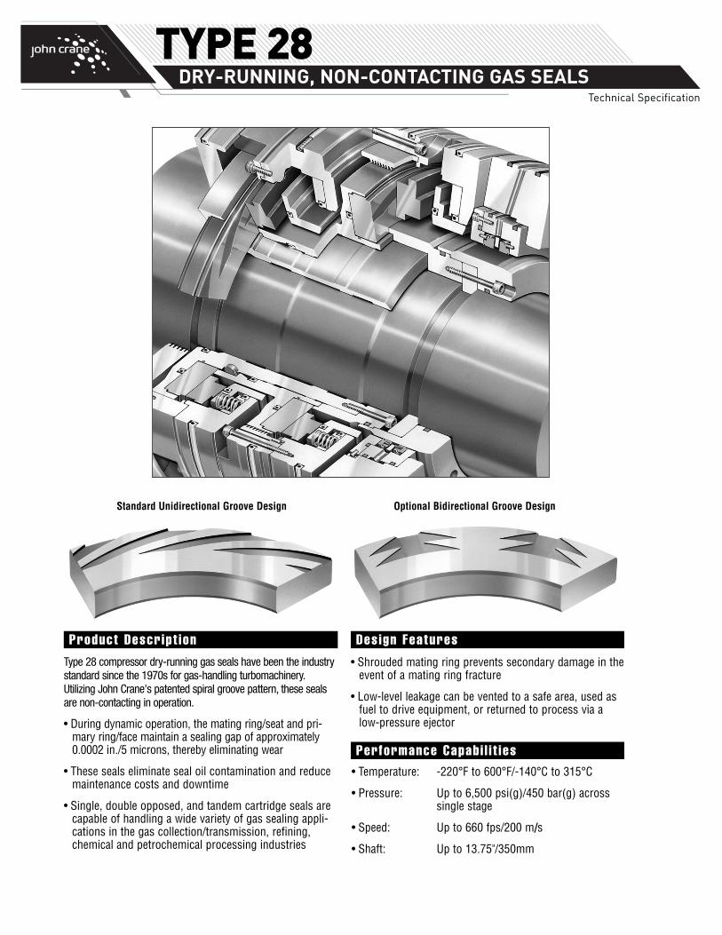
Optional Bidirectional Groove DesignStandard Unidirectional Groove Design
• Shrouded mating ring prevents secondary damage in theevent of a mating ring fracture
• Low-level leakage can be vented to a safe area, used asfuel to drive equipment, or returned to process via alow-pressure ejector
Type 28 compressor dry-running gas seals have been the industrystandard since the 1970s for gas-handling turbomachinery.Utilizing John Crane's patented spiral groove pattern, these sealsare non-contacting in operation.
• During dynamic operation, the mating ring/seat and pri-mary ring/face maintain a sealing gap of approximately0.0002 in./5 microns, thereby eliminating wear
• These seals eliminate seal oil contamination and reducemaintenance costs and downtime
• Single, double opposed, and tandem cartridge seals arecapable of handling a wide variety of gas sealing appli-cations in the gas collection/transmission, refining,chemical and petrochemical processing industries
• Temperature: -220°F to 600°F/-140°C to 315°C
• Pressure: Up to 6,500 psi(g)/450 bar(g) across single stage
• Speed: Up to 660 fps/200 m/s
• Shaft: Up to 13.75"/350mm
Product Descript ion Design Features
Performance Capabi l i t ies
TYPE 28 DRY-RUNNING, NON-CONTACTING GAS SEALS
Technical Specification
( )
( )
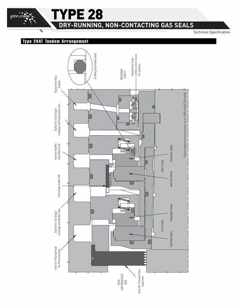
Type 28AT Tandem Arrangement
TYPE 28 DRY-RUNNING, NON-CONTACTING GAS SEALS
Technical Specification
Inle
t for
Filt
ered
Sea
l (o
r P
roce
ss) G
asO
utle
t for
1st
Sta
ge
Leak
age
and
Buf
fer
Gas
Inle
t for
Buf
fer
Gas
(Opt
iona
l)O
utle
t for
2nd
Sta
ge
Leak
age
and
Sepa
ratio
n G
asSe
para
tion
Gas
Su
pply
Poly
mer
Sec
onda
ry S
eal
Sepa
ratio
n Se
al -
co
ntac
t Joh
n C
rane
fo
r op
tions
*Typ
ical
App
licat
ion
pres
sure
s up
to 2
,650
psi
(g)/
180
bar(
g)
BEA
RIN
G
CAV
ITY
SEAL
(O
R P
RO
CES
S)
GAS
al (O
r P
roce
ss) G
as
Laby
rint
h
MAT
ING
RIN
GM
ATIN
G R
ING
PR
IMAR
Y R
ING
PR
IMAR
Y R
ING
1ST
STAG
E2N
D S
TAG
E
Inte
rsta
ge L
abyr
inth
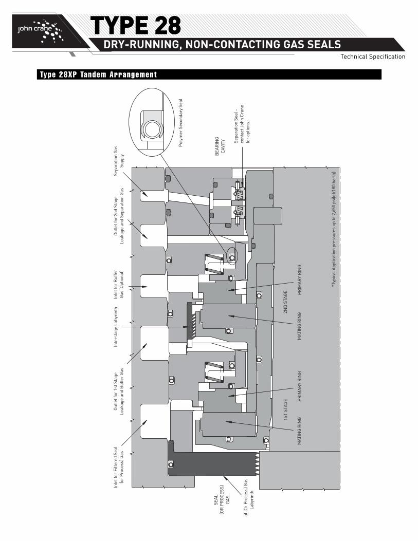
Type 28XP Tandem Arrangement
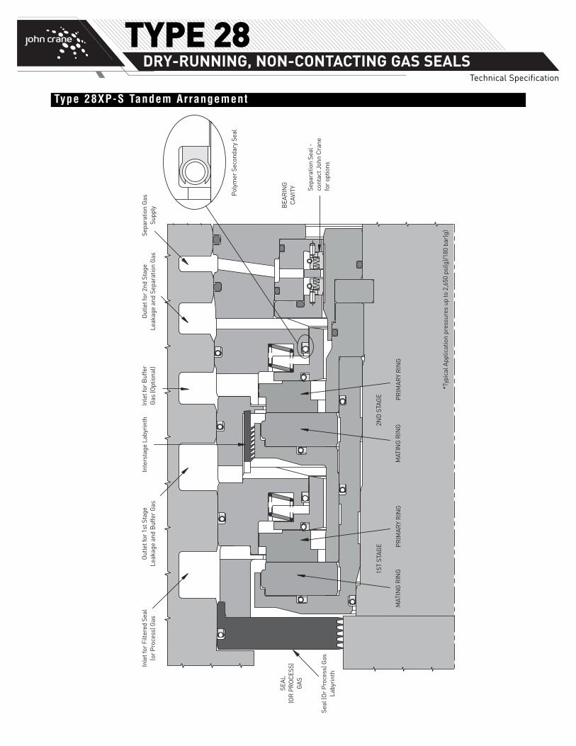
Type 28XP-S Tandem Arrangement
Inle
t for
Filt
ered
Sea
l (o
r P
roce
ss) G
asO
utle
t for
1st
Sta
ge
Leak
age
and
Buf
fer
Gas
Inle
t for
Buf
fer
Gas
(Opt
iona
l)O
utle
t for
2nd
Sta
ge
Leak
age
and
Sepa
ratio
n G
asSe
para
tion
Gas
Su
pply
Poly
mer
Sec
onda
ry S
eal
Sepa
ratio
n Se
al -
co
ntac
t Joh
n C
rane
fo
r op
tions
*Typ
ical
App
licat
ion
pres
sure
s up
to 2
,650
psi
(g)/
180
bar(
g)
BEA
RIN
G
CAV
ITY
SEAL
(O
R P
RO
CES
S)
GAS
Seal
(Or
Pro
cess
) Gas
La
byri
nth
MAT
ING
RIN
GM
ATIN
G R
ING
PR
IMAR
Y R
ING
PR
IMAR
Y R
ING
1ST
STAG
E2N
D S
TAG
E
Inte
rsta
ge L
abyr
inth
TYPE 28 DRY-RUNNING, NON-CONTACTING GAS SEALS
Technical Specification
TYPE 28 DRY-RUNNING, NON-CONTACTING GAS SEALS
Technical Specification
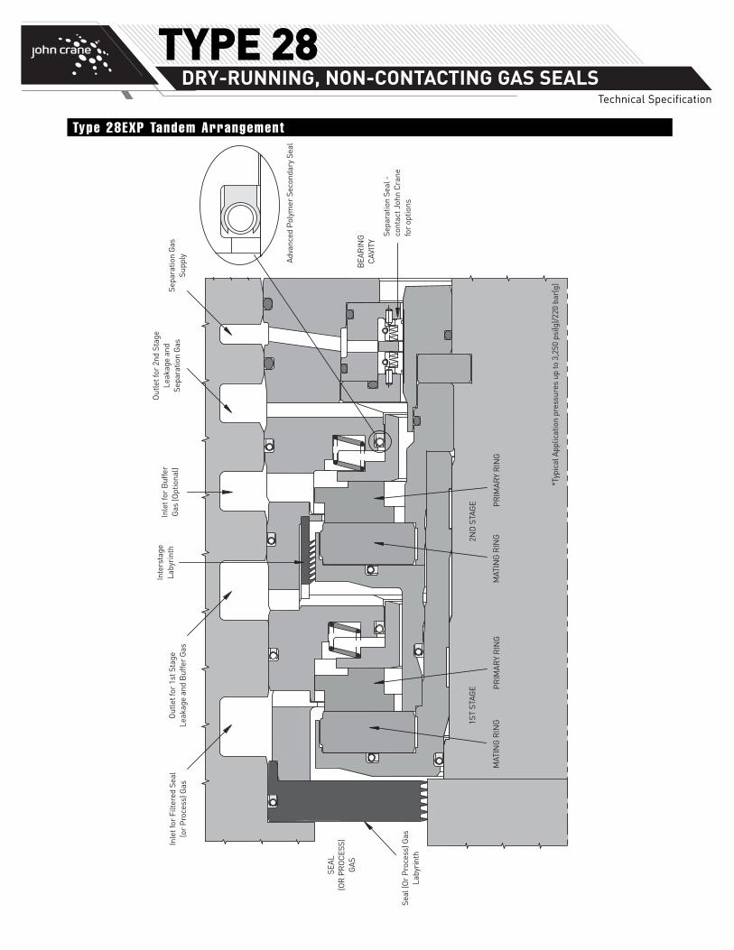
Inle
t for
Filt
ered
Sea
l (o
r P
roce
ss) G
asO
utle
t for
1st
Sta
ge
Leak
age
and
Buf
fer
Gas
Inle
t for
Buf
fer
Gas
(Opt
iona
l)
Out
let f
or 2
nd S
tage
Le
akag
e an
d Se
para
tion
Gas
Sepa
ratio
n G
as
Supp
ly Adva
nced
Pol
ymer
Sec
onda
ry S
eal
Sepa
ratio
n Se
al -
co
ntac
t Joh
n C
rane
fo
r op
tions
*Typ
ical
App
licat
ion
pres
sure
s up
to 3
,250
psi
(g)/
220
bar(
g)
BEA
RIN
G
CAV
ITY
SEAL
(O
R P
RO
CES
S)
GAS
Seal
(Or
Pro
cess
) Gas
La
byri
nth
MAT
ING
RIN
GM
ATIN
G R
ING
PR
IMAR
Y R
ING
PR
IMAR
Y R
ING
1ST
STAG
E2N
D S
TAG
E
Inte
rsta
ge
Laby
rint
h
Type 28EXP Tandem Arrangement
TYPE 28 DRY-RUNNING, NON-CONTACTING GAS SEALS
Technical Specification
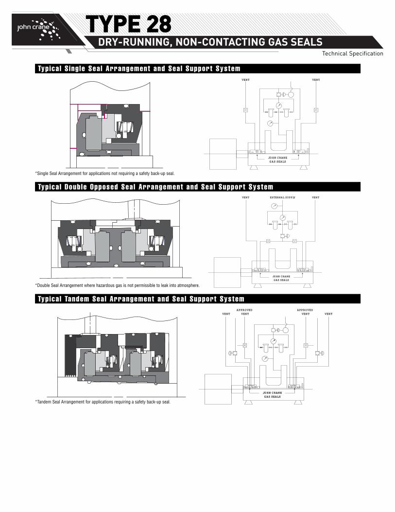
VENTVENT EXTERNAL SUPPLY
JOHN CRANEGAS SEALS
VENTVENT
JOHN CRANEGAS SEALS
JOHN CRANEGAS SEALS
APPROVED VENT
APPROVED VENT VENTVENT
*Single Seal Arrangement for applications not requiring a safety back-up seal.
*Tandem Seal Arrangement for applications requiring a safety back-up seal.
*Double Seal Arrangement where hazardous gas is not permissible to leak into atmosphere.
Typica l S ing le Sea l Arrangement and Seal Support System
Typica l Double Opposed Seal Arrangement and Seal Support System
Typica l Tandem Seal Arrangement and Seal Support System
TYPE 28 DRY-RUNNING, NON-CONTACTING GAS SEALS
Technical Specification
5
4
3
2
1
0
125
100
75
50
25
02.187 3.187 4.187 5.187 6.125 7.125 8.125 9.125 10.125
50 100 150 200 250
Seal Size
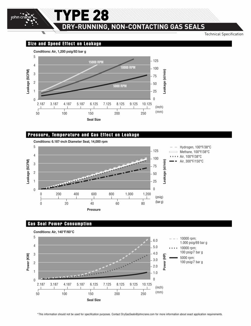
5000 RPM
10000 RPM15000 RPM
Leak
age
(SC
FM)
Leak
age
(sl/m
in)
(inch)(mm)
Conditions: Air, 1,200 psig/83 bar g
6.0
5.0
4.0
3.0
2.0
1.0
0
10000 rpm;1.000 psig/69 bar g10000 rpm;100 psig/7 bar g
5000 rpm;100 psig/7 bar g
2.187 3.187 4.187 5.187 6.125 7.125 8.125 9.125 10.125
50 100 150 200 250
Seal Size
Pow
er (K
W)
Pow
er (H
P)
(inch)(mm)
Conditions: Air, 140°F/60°C
5
4
3
2
1
0
0 200 400 600 800 1,000 1,200
800 20 40 60
Hydrogen, 100°F/38°CMethane, 100°F/38°CAir, 100°F/38°CAir, 300°F/150°C
5
4
3
2
1
0
Leak
age
(SC
FM)
Pressure
(psig)(bar g)
Conditions: 6.187-inch Diameter Seal, 14,000 rpm
125
100
75
50
25
0
Leak
age
(sl/m
in)
*This information should not be used for specification purposes. Contact [email protected] for more information about exact application requirements.
Size and Speed E f fect on Leakage
Pressure, Temperature and Gas E f fect on Leakage
Gas Seal Power Consumpt ion
If the products featured will be used in a potentially dangerous and/or hazardous process, your John Crane representative should be consulted prior totheir selection and use. In the interest of continuous development, John Crane Companies reserve the right to alter designs and specifications withoutprior notice. It is dangerous to smoke while handling products made from PTFE. Old and new PTFE products must not be incinerated. ISO 9001 andISO14001 Certified, details available on request.
©2015 John Crane Revised 10/15 www.johncrane.com TD-28AT/28XP/28XPS/28EXP
North AmericaUnited States of America
Tel: 1-847-967-2400Fax: 1-847-967-3915
EuropeUnited Kingdom
Tel: 44-1753-224000Fax: 44-1753-224224
Latin AmericaBrazil
Tel: 55-11-3371-2500Fax: 55-11-3371-2599
Middle East & AfricaUnited Arab Emirates
Tel: 971-481-27800Fax: 971-488-62830
Asia PacificSingapore
Tel: 65-6518-1800Fax: 65-6518-1803
TYPE 28 DRY-RUNNING, NON-CONTACTING GAS SEALS
Technical Specification