Embed Size (px)
Citation preview
Interim Guidelines Advisory No. 2 SAC 99-01
Post-earthquake Repair and Modification
6-1
6. POST-EARTHQUAKE REPAIR AND MODIFICATION
6.1 Scope
There are no modifications to the Guidelines or Commentary of Section 6.1 at this time.
6.2 Shoring
There are no modifications to the Guidelines or Commentary of Section 6.2 at this time.
6.3 Repair Details
There are no modifications to the Guidelines or Commentary of Section 6.3 at this time.
6.4 Preparation
There are no modifications to the Guidelines or Commentary of Section 6.4 at this time.
6.5 Execution
There are no modifications to the Guidelines or Commentary of Section 6.5 at this time.
6.6 STRUCTURAL MODIFICATION
6.6.1 Definition of Modification
There are no modifications to the Guidelines or Commentary of Section 6.6.1 at this time.
6.6.2 Damaged vs. Undamaged Connections
There are no modifications to the Guidelines or Commentary of Section 6.6.2 at this time.
6.6.3 Criteria
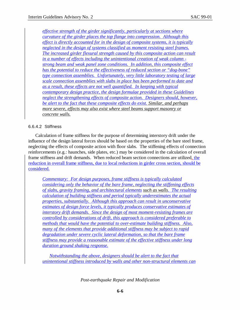
Connection modification intended to permit inelastic frame behavior should be proportionedso that the required plastic deformation of the frame may be accommodated through thedevelopment of plastic hinges at pre-determined locations within the girder spans, as indicated inFigure 6-12 Figure 6.6.3-1. Beam-column connections should be designed with sufficientstrength (through the use of cover plates, haunches, side plates, etc.) to force development of theplastic hinge away from the column face. This condition may also be attained through localweakening of the beam section, at the desired location for plastic hinge formation. All elementsof the connection should have adequate strength to develop the forces resulting from the

Interim Guidelines Advisory No. 2 SAC 99-01
Post-earthquake Repair and Modification
6-2
formation of the plastic hinge at the predetermined location, together with forces resulting fromgravity loads.
Plastic Hinges
Deformed frame shapeUndeformedframe
L’
L
h
drift angle - θ
Figure 6-12 Figure 6.6.3-1 - Desired Plastic Frame Behavior
Commentary: Nonlinear deformation of frame structures is typicallyaccommodated through the development of inelastic flexural or shear strainswithin discrete regions of the structure. At large inelastic strains these regionscan develop into plastic hinges, which can accommodate significant concentratedrotations at constant (or nearly constant) load through yielding at tensile fibersand buckling at compressive fibers. If a sufficient number of plastic hingesdevelop in a frame, a mechanism is formed and the frame can deform laterally ina plastic manner. This behavior is accompanied by significant energydissipation, particularly if a number of members are involved in the plasticbehavior, as well as substantial local damage to the highly strained elements.The formation of hinges in columns, as opposed to beams, is undesirable, as thisresults in the formation of weak story mechanisms with relatively few elementsparticipating, and consequently little energy dissipation occurring. In addition,such mechanisms also result in local damage to critical gravity load bearingelements.
The prescriptive connection contained in the UBC and NEHRP RecommendedProvisions prior to the Northridge Earthquake was based on the assumeddevelopment of plastic hinge zones within the beams at adjacent to the face of thecolumn, or within the column panel zone itself. If the plastic hinge develops inthe column panel zone, the resulting column deformation results in very largesecondary stresses on the beam flange to column flange joint, a condition whichcan contribute to brittle failure. If the plastic hinge forms in the beam, at the faceof the column, this can result in very large through-thickness strain demands on

Interim Guidelines Advisory No. 2 SAC 99-01
Post-earthquake Repair and Modification
6-3
the column flange material and large inelastic strain demands on the weld metaland surrounding heat affected zones stress and strain demands on the weldedbeam flange to column flange joint. These conditions can also lead to brittlejoint failure. Although ongoing research may reveal conditions of materialproperties, design and detailing configurations that permit connections withyielding occurring at the column face to perform reliably, for the present, it isrecommended In order to achieve more reliable performance, it is recommendedthat the connection of the beam to the column be modified to be sufficientlystrong to force the inelastic action (plastic hinge) away from the column face.Plastic hinges in steel beams have finite length, typically on the order of half thebeam depth. Therefore, the location for the plastic hinge should be shifted atleast that distance away from the face of the column. When this is done, theflexural demands on the columns are increased. Care must be taken to assurethat weak column conditions are not inadvertently created by local strengtheningof the connections.
It should be noted that connection modifications of the type described above,while believed to be effective in preventing brittle connection fractures, will notprevent structural damage from occurring. Brittle connection fractures areundesirable because they result in a substantial reduction in the lateral-force-resisting strength of the structure which, in extreme cases, can result in instabilityand collapse. Connections modified as described in these Interim Guidelinesshould experience many fewer such brittle fractures than unmodified connections.However, the formation of a plastic hinge within the span of a beam is not acompletely benign event. Beams which have formed such hinges may exhibitlarge buckling and yielding deformation, damage which typically must berepaired. The cost of such repairs could be comparable to the costs incurred inrepairing fracture damage experienced in the Northridge Earthquake. Theprimary difference is that life safety protection will be significantly enhanced andmost structures that have experienced such plastic deformation damage shouldcontinue to be safe for occupancy while repairs are made.
If the types of damage described above are unacceptable for a given building,then alternative methods of structural modification should be considered that willreduce the plastic deformation demands on the structure during a strongearthquake. Appropriate methods of achieving such goals include the installationof supplemental braced frames, energy dissipation systems, and similarsystematic modifications of the building’s basic lateral force resisting system.
It is important to recognize that in frames with relatively short bays, theflexural hinging indicated in Figure 6.6.3-1 may not be able to form. If theeffective flexural length (L’ in the figure) of beams in a frame becomes too short,then the beams or girders will yield in shear before zones of flexural plasticity

Interim Guidelines Advisory No. 2 SAC 99-01
Post-earthquake Repair and Modification
6-4
can form, resulting in an inelastic behavior that is more like that of aneccentrically braced frame than that of a moment frame. This behavior mayinadvertently occur in frames in which relatively large strengthened connections,such as haunches, cover plates or side plates have been used on beams withrelatively short spans. This behavior is illustrated in Figure 6.6.3-2.
The guidelines contained in this section are intended to address the design offlexurally dominated moment resisting frames. When utilizing these guidelines, itis important to confirm that the configuration of the structure is such that thepresumed flexural hinging can actually occur. It is possible that shear yielding offrame beams, such as that schematically illustrated in Figure 6.6.3-2 may be adesirable behavior mode. However, to date, there has not been enough researchconducted into the behavior of such frames to develop recommended designguidelines. If modifications to an existing frame result in such a configurationdesigners should consider referring to the code requirements for eccentricallybraced frames. Particular care should be taken to brace the shear link of suchbeams against lateral-torsional buckling and also to adequately stiffen the websto avoid local buckling following shear plastification.
Shear Link
Shear Link
Figure 6.6.3-2 Shear Yielding Dominated Behavior of Short Bay Frames
6.6.4 Strength and Stiffness
6.6.4.1 Strength
When these Interim Guidelines require determination of the strength of a framing element orcomponent, this shall be calculated in accordance with the criteria contained in UBC-94, Section

Interim Guidelines Advisory No. 2 SAC 99-01
Post-earthquake Repair and Modification
6-5
2211.4.2 {NEHRP-91 Section 10.2, except that the factor φ should be taken as 1.0}, restated asfollows:
2211.4.1 Member strength. Where this section requires that the strength of the member bedeveloped, the following shall be used:
Flexure Ms = Z Fy
Shear Vs = 0.55 Fy d tAxial compression Psc = 1.7 Fa AAxial tension Pst = Fy AConnectors Full Penetration welds Fy A Partial Penetration welds 1.7 allowable (see commentary) Bolts and fillet welds 1.7 allowable
Alternatively, the criteria contained in the 1997 edition of the AISC Seismic Provisions forStructural Steel Buildings (AISC, 1997) may be used.
Commentary: At the time the Interim Guidelines were first published, they werebased on the 1994 edition of the Uniform Building Code and the 1994 edition ofthe NEHRP Provisions. In the time since that initial publication, more recenteditions of both documents have been published, and codes based on thesedocuments have been adopted by some jurisdictions. In addition, the AmericanInstitute of Steel Construction has adopted a major revision to its SeismicProvisions for Structural Steel Buildings (AISC Seismic Provisions), largelyincorporating, with some modification, the recommendations contained in theInterim Guidelines. This updated edition of the AISC Seismic Provisions hasbeen incorporated by reference into the 1997 edition of the NEHRP Provisionsand has also been adopted by some jurisdictions as an amendment to the modelbuilding codes. Structural upgrades designed to comply with the requirements ofthe 1997 AISC Seismic Provisions may be deemed to comply with the intent ofthese Interim Guidelines. Where reference is made herein to the requirements ofthe 1994 Uniform Building Code or 1994 NERHP Provisions, the parallelprovisions of the 1997 editions may be used instead, and should be used in thosejurisdictions that have adopted codes based on these updated standards.
Partial penetration welds are not recommended for tension applications incritical connections resisting seismic induced stresses. The geometry of partialpenetration welds creates a notch-like condition that can initiate brittle fractureunder conditions of high tensile strain.
Many WSMF structures are constructed with concrete floor slabs that areprovided with positive shear attachment between the slab and the top flanges ofthe girders of the moment-resisting frames. Although not generally accounted forin the design of the frames, the resulting composite action can increase the
Interim Guidelines Advisory No. 2 SAC 99-01
Post-earthquake Repair and Modification
6-6
effective strength of the girder significantly, particularly at sections wherecurvature of the girder places the top flange into compression. Although thiseffect is directly accounted for in the design of composite systems, it is typicallyneglected in the design of systems classified as moment resisting steel frames.The increased girder flexural strength caused by this composite action can resultin a number of effects including the unintentional creation of weak column -strong beam and weak panel zone conditions. In addition, this composite effecthas the potential to reduce the effectiveness of reduced section or “dog-bone”type connection assemblies. Unfortunately, very little laboratory testing of largescale connection assemblies with slabs in place has been performed to date andas a result, these effects are not well quantified. In keeping with typicalcontemporary design practice, the design formulae provided in these Guidelinesneglect the strengthening effects of composite action. Designers should, however,be alert to the fact that these composite effects do exist. Similar, and perhapsmore severe, effects may also exist where steel beams support masonry orconcrete walls.
6.6.4.2 Stiffness
Calculation of frame stiffness for the purpose of determining interstory drift under theinfluence of the design lateral forces should be based on the properties of the bare steel frame,neglecting the effects of composite action with floor slabs. The stiffening effects of connectionreinforcements (e.g.: haunches, side plates, etc.) may be considered in the calculation of overallframe stiffness and drift demands. When reduced beam section connections are utilized, thereduction in overall frame stiffness, due to local reductions in girder cross section, should beconsidered.
Commentary: For design purposes, frame stiffness is typically calculatedconsidering only the behavior of the bare frame, neglecting the stiffening effectsof slabs, gravity framing, and architectural elements such as walls. The resultingcalculation of building stiffness and period typically underestimates the actualproperties, substantially. Although this approach can result in unconservativeestimates of design force levels, it typically produces conservative estimates ofinterstory drift demands. Since the design of most moment-resisting frames arecontrolled by considerations of drift, this approach is considered preferable tomethods that would have the potential to over-estimate building stiffness. Also,many of the elements that provide additional stiffness may be subject to rapiddegradation under severe cyclic lateral deformation, so that the bare framestiffness may provide a reasonable estimate of the effective stiffness under longduration ground shaking response.
Notwithstanding the above, designers should be alert to the fact thatunintentional stiffness introduced by walls and other non-structural elements can

Interim Guidelines Advisory No. 2 SAC 99-01
Post-earthquake Repair and Modification
6-7
significantly alter the behavior of the structure in response to ground shaking. Ofparticular concern, if these elements are not uniformly distributed throughout thestructure, or isolated from its response, they can cause soft stories and torsionalirregularities, conditions known to result in poor behavior.
6.6.5 Plastic Rotation Capacity
The plastic rotation capacity of modified connections should reflect realistic estimates of therequired level of plastic rotation demand. In the absence of detailed calculations of rotationdemand, connections should be shown to be capable of developing a minimum plastic rotationcapacity on the order of 0.025 to 0.030 radian. The demand may be lower when braced frames,supplemental damping, base isolation, or other elements are introduced into the moment framesystem, to control its lateral deformation; when the design ground motion is relatively low in therange of predominant periods for the structure; and when the frame is sufficiently strong and stiff.
As used in these Guidelines, plastic rotation is defined as the plastic chord rotation angle. Theplastic chord rotation angle is calculated using the rotated coordinate system shown in Fig. 6.6.5-1 as the plastic deflection of the beam or girder, at the point of inflection (usually at the center ofits span,) ∆CI, divided by the distance between the center of the beam span and the centerline ofthe panel zone of the beam column connection, LCL. This convention is illustrated in Figure 6.6.5-1.
It is important to note that this definition of plastic rotation is somewhat different than theplastic rotation that would actually occur within a discrete plastic hinge in a frame model similarto that shown in Figure 6.6.3-1. These two quantities are related to each other, however, and ifone of them is known, the other may be calculated from Eq. 6.6.5-1.
cL
cL
Beam span center line
∆CL
LCL
θ pCL
CLL= ∆
Plastic hinge
lh
Figure 6.6.5-1 Calculation of Plastic Rotation Angle
Interim Guidelines Advisory No. 2 SAC 99-01
Post-earthquake Repair and Modification
6-8
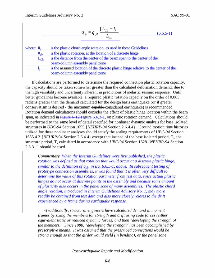
( )θ θp ph
CL h
CL
L lL
= − (6.6.5-1)
where: θp is the plastic chord angle rotation, as used in these Guidelines θph is the plastic rotation, at the location of a discrete hinge LCL is the distance from the center of the beam span to the center of the beam-column assembly panel zone lh is the assumed location of the discrete plastic hinge relative to the center of the beam-column assembly panel zone
If calculations are performed to determine the required connection plastic rotation capacity,the capacity should be taken somewhat greater than the calculated deformation demand, due tothe high variability and uncertainty inherent in predictions of inelastic seismic response. Untilbetter guidelines become available, a required plastic rotation capacity on the order of 0.005radians greater than the demand calculated for the design basis earthquake (or if greaterconservatism is desired - the maximum capable considered earthquake) is recommended.Rotation demand calculations should consider the effect of plastic hinge location within the beamspan, as indicated in Figure 6-12 Figure 6.6.3-1, on plastic rotation demand. Calculations shouldbe performed to the same level of detail specified for nonlinear dynamic analysis for base isolatedstructures in UBC-94 Section 1655 {NEHRP-94 Section 2.6.4.4}. Ground motion time historiesutilized for these nonlinear analyses should satisfy the scaling requirements of UBC-94 Section1655.4.2 {NEHRP-94 Section 2.6.4.4} except that instead of the base isolated period, TI, thestructure period, T, calculated in accordance with UBC-94 Section 1628 {NEHRP-94 Section2.3.3.1} should be used.
Commentary. When the Interim Guidelines were first published, the plasticrotation was defined as that rotation that would occur at a discrete plastic hinge,similar to the definition of θph. in Eq. 6.6.5-1, above. In subsequent testing ofprototype connection assemblies, it was found that it is often very difficult todetermine the value of this rotation parameter from test data, since actual plastichinges do not occur at discrete points in the assembly and because some amountof plasticity also occurs in the panel zone of many assemblies. The plastic chordangle rotation, introduced in Interim Guidelines Advisory No. 1, may morereadily be obtained from test data and also more closely relates to the driftexperienced by a frame during earthquake response.
Traditionally, structural engineers have calculated demand in momentframes by sizing the members for strength and drift using code forces (eitherequivalent static or reduced dynamic forces) and then "developing the strength ofthe members." Since 1988, "developing the strength" has been accomplished byprescriptive means. It was assumed that the prescribed connections would bestrong enough so that the girder would yield (in bending), or the panel zone

Interim Guidelines Advisory No. 2 SAC 99-01
Post-earthquake Repair and Modification
6-9
would yield (in shear) in a nearly perfectly plastic manner producing the plasticrotations necessary to dissipate the energy of the earthquake. It is now knownthat the prescriptive connection is often incapable of behaving in this manner.
In the 1994 Northridge earthquake, many moment-frame connectionsfractured with little evidence of plastic hinging of the girders or yielding of thecolumn panel zones. Testing of moment frame connections both prior to andsubsequent to the earthquake suggests that the standard welded flange-bolted webconnection is unable to reliably provide plastic rotations beyond about 0.005radian for all ranges of girder depths and often fails below that level. Thus, forframes designed for code forces and for the code drift limits, new connectionconfigurations must be developed to reliably accommodate such rotation withoutbrittle fracture.
In order to develop reasonable estimates of the plastic rotation demands on aframe’s connections, it is necessary to perform inelastic time history analyses.For regular structures, approximations of the plastic rotation demands can beobtained from linear elastic analyses. Analytical research (Newmark and Hall -1982) suggests that for structures having the dynamic characteristics of mostWSMF buildings, and for the ground motions typical of western US earthquakes,the total frame deflections obtained from an unreduced (no R or Rw factor)dynamic analysis provide an approximate estimate of those which would beexperienced by the inelastic structure. For the typical spectra contained in thebuilding code, this would indicate expected drift ratios on the order of 1%. Thedrift demands in a real structure, responding inelastically, tend to concentrate ina few stories, rather than being uniformly distributed throughout the structure’sheight. Therefore, it is reasonable to expect typical drift demands in individualstories on the order of 1.5% to 2% of the story height. As a roughapproximation, the drift demand may be equated to the joint rotation demand,yielding expected rotation demands on the order of perhaps 2%. Since there isconsiderable variation in ground motion intensity and spectra, as well as theinelastic response of buildings to these ground motions, conservatism in selectionof an appropriate connection rotation demand is warranted.
In recent testing of large scale subassemblies incorporating modifiedconnection details, conducted by SAC and others, when the connection design wasable to achieve a plastic rotation demand of 0.025 radians or more for severalcycles, the ultimate failure of the subassembly generally did not occur in theconnection, but rather in the members themselves. Therefore, the statedconnection capacity criteria would appear to result in connections capable ofproviding reliable performance.
It should be noted that the connection assembly capacity criteria for themodification of existing buildings, recommended by these Interim Guidelines, is

Interim Guidelines Advisory No. 2 SAC 99-01
Post-earthquake Repair and Modification
6-10
somewhat reduced compared to that recommended for new buildings (Chapter 7).This is typical of approaches normally taken for existing structures. For newbuildings, these Interim Guidelines discourage building-specific calculation ofrequired plastic rotation capacity for connections and instead, encourage thedevelopment of highly ductile connection designs. For existing buildings, such anapproach may lead to modification designs that are excessively costly, as well asthe modification of structures which do not require such modification.Consequently, an approach which permits the development of semi-ductileconnection designs, with sufficient plastic rotation capacity to withstand theexpected demands from a design earthquake is adopted. It should be understoodthat buildings modified to this reduced criteria will not have the same reliabilityas new buildings, designed in accordance with the recommendations of Chapter7. The criteria of Chapter 7 could be applied to existing buildings, if superiorreliability is desired.
When performing inelastic frame analysis, in order to determine the requiredconnection plastic rotation capacity, it is important to accurately account for thelocations at which the plastic hinges will occur. Simplified models, whichrepresent the hinge as occurring at the face of the column, maywill underestimatethe plastic rotation demand. This problem becomes more severe as the columnspacing, L, becomes shorter and the distance between plastic hinges, L’, agreater portion of the total beam span. Eq. 6.6.5-1 may be used to convertcalculated values of plastic rotation at a hinge remotely located from the column,to the chord angle rotation, used for the definition of acceptance criteriacontained in these Guidelines. In extreme cases, the girder will not form plastichinges at all, but instead, will develop a shear yield, similar to an eccentricbraced frame.
6.6.6 Connection Qualification and Design
Modified girder-column connections may be qualified by testing or designed usingcalculations. Qualification by testing is the preferred approach. Preliminary designs ofconnections to be qualified by test may be obtained using the calculation procedures of Section6.6.6.3. The procedures of that section may also be used to calibrate previous tests of similarconnection configurations to slightly different applications, by extrapolation. Extrapolation of testresults should be limited to connections of elements having similar geometries and materialspecifications as the tested connections. Designs based on calculation alone should be subject toqualified independent third party review.
Commentary: Because of the cost of testing, use of calculations for interpolationor extrapolation of test results is desirable. How much extrapolation should beaccepted is a difficult decision. As additional testing is done, more informationmay be available on what constitutes "conservative" testing conditions, thereby
Interim Guidelines Advisory No. 2 SAC 99-01
Post-earthquake Repair and Modification
6-11
allowing easier decisions relative to extrapolating tests to actual conditions whichare likely to be less demanding than the tests. For example, it is hypothesizedthat connections of shallower, thinner flanged members are likely to be morereliable than similar connections consisting of deeper, thicker flanged members.Thus, it may be possible to test the largest assemblages of similar details andextrapolate to the smaller member sizes? - at least within comparable membergroup families. However, there is evidence to suggest that extrapolation of testresults to assemblies using members of reduced size is not always conservative.In a recent series of tests of cover plated connections, conducted at the Universityof California at San Diego, a connection assembly that produced acceptableresults for one family of beam sizes, W24, did not behave acceptably when thebeam depth was reduced significantly to W18. In that project, the change inrelative flexibilities of the members and connection elements resulted in a shift inthe basic behavior of the assembly and initiation of a failure mode that was notobserved in the specimens with larger member sizes. In order to minimize thepossibility of such occurrences, when extrapolation of test results is performed, itshould be done with a basic understanding of the behavior of the assembly, andthe likely effects of changes to the assembly configuration on this behavior. Testresults should not be extrapolated to assembly configurations that are expected tobehave differently than the tested configuration. Extrapolation or interpolationof results with differences in welding procedures, details or material properties iseven more difficult.
6.6.6.1 Qualification Test Protocol
There are no modifications to the Guidelines or Commentary of Section 6.6.6.1 at this time.
6.6.6.2 Acceptance Criteria
The minimum acceptance criteria for connection qualification for specimens tested inaccordance with these Interim Guidelines should be as follows:
a) The connection should develop beam plastic rotations as indicated in Section 6.6.5, forat least one complete cycle.
b) The connection should develop a minimum strength equal to 80% of the plasticstrength of the girder, calculated using minimum specified yield strength Fy,throughout the loading history required to achieve the required plastic rotationcapacity, as indicated in a), above.
c) The connection should exhibit ductile behavior throughout the loading history. Aspecimen that exhibits a brittle limit state (e.g. complete flange fracture, columncracking, through-thickness failures of the column flange, fractures in welds subject to
Interim Guidelines Advisory No. 2 SAC 99-01
Post-earthquake Repair and Modification
6-12
tension, shear tab cracking, etc. ) prior to reaching the required plastic rotation shall beconsidered unsuccessful.
d) Throughout the loading history, until the required plastic rotation is achieved, theconnection should be judged capable of supporting dead and live loads required by thebuilding code. In those specimens where axial load is applied during the testing, thespecimen should be capable of supporting the applied load throughout the loadinghistory.
The evaluation of the test specimen’s performance should consistently reflect the relevant limitstates. For example, the maximum reported moment and the moment at the maximum plasticrotation are unlikely to be the same. It would be inappropriate to evaluate the connection usingthe maximum moment and the maximum plastic rotation in a way that implies that they occurredsimultaneously. In a similar fashion, the maximum demand on the connection should beevaluated using the maximum moment, not the moment at the maximum plastic rotation unless thebehavior of the connection indicated that this limit state produced a more critical condition in theconnection.
Commentary: Many connection configurations will be able to withstandplastic rotations on the order of 0.025 radians or more, but will have sustainedsignificant damage and degradation of stiffness and strength in achieving thisdeformation. The intent of the acceptance criteria presented in this Section is toassure that when connections experience the required plastic rotation demand,they will still have significant remaining ability to participate in the structure’slateral load resisting system.
In evaluating the performance of specimens during testing, it is important todistinguish between brittle behavior and ductile behavior. It is not uncommon forsmall cracks to develop in specimens after relatively few cycles of inelasticdeformation. In some cases these initial cracks will rapidly lead to ultimatefailure of the specimen and in other cases they will remain stable, perhapsgrowing slowly with repeated cycles, and may or may not participate in theultimate failure mode. The development of minor cracks in a specimen, prior toachievement of the target plastic rotation demand should not be cause forrejection of the design if the cracks remain stable during repeated cycling.Similarly, the occurrence of brittle fracture at inelastic rotations significantly inexcess of the target plastic rotation should not be cause for rejection of thedesign.
6.6.6.3 Calculations
There are no modifications to the Guidelines or Commentary of Section 6.6.6.3 at this time.

Interim Guidelines Advisory No. 2 SAC 99-01
Post-earthquake Repair and Modification
6-13
6.6.6.3.1 Material Strength Properties
In the absence of project specific material property information (for example, mill testreports), the values listed in Table 6-3 Table 6.6.6.3.1-1 should be used to determine the strengthof steel shape and plate for purposes of calculation. The permissible strength for weld metalshould be taken in accordance with the building code.
Table 6-3Table 6.6.6.3-1 - Properties for Use in Connection Modification Design
Material Fy (ksi) Fy m (ksi) Fu (ksi)A36 Beam 36 1 1
Dual Certified Beam Axial, Flexural Shape Group 1 Shape Group 2 Shape Group 3 Shape Group 4 Through-Thickness
50
-
552
582
572
542
-
65 min.
Note 3A572 Column/Beam Axial, Flexural Shape Group 1 Shape Group 2 Shape Group 3 Shape Group 4 Shape Group 5 Through-Thickness
50
-
582
582
572
572
552
-
65 min.
Note 3A992 Structural Shape1 Use same values as for A572, Gr. 50Notes:1. See Commentary2. Based on coupons from web. For thick flanges,
the Fy flange is approximately 0.95 Fy web.3. See Commentary
Commentary: Table 6-3, Note 1 - The material properties for steel nominallydesignated on the construction documents as ASTM A36 can be highly variableand in recent years, steel meeting the specified requirements for both ASTM A36and A572 has routinely been incorporated in projects calling for A36 steel.Consequently, unless project specific data is available to indicate the actualstrength of material incorporated into the project, the properties for ASTM A572steel should be assumed when ASTM A36 is indicated on the drawings, and theassumption of a higher yield stress results in a more severe design condition.
The ASTM A992 specification was specifically developed by the steel industryin response to expressed concerns of the design community with regard to thepermissible variation in chemistry and mechanical properties of structural steelunder the A36 and A572 specifications. This new specification, which wasadopted in late 1998, is very similar to ASTM A572, except that it includessomewhat more restrictive limits on chemistry and on the permissible variation in

Interim Guidelines Advisory No. 2 SAC 99-01
Post-earthquake Repair and Modification
6-14
yield and ultimate tensile stress, as well as the ratio of yield to tensile strength.At this time, no statistical data base is available to estimate the actualdistribution of properties of material produced to this specification. However, theproperties are likely to be very similar, albeit with less statistical scatter, to thoseof material recently produced under ASTM A572, Grade 50.
Table 6-3Table 6.6.6.3-1, Note 3 - In the period immediately following theNorthridge earthquake, the Seismology Committee of the Structural EngineersAssociation of California and the International Conference of Building Officialsissued Interim Recommendation No. 2 (SEAOC-1995) to provide guidance on thedesign of moment resisting steel frame connections. Interim RecommendationNo. 2 included a recommendation that the through-thickness stress demand oncolumn flanges be limited to a value of 40 ksi, applied to the projected area ofbeam flange attachment. This value was selected somewhat arbitrarily, to ensurethat through-thickness yielding did not initiate in the column flanges of moment-resisting connections and because it was consistent with the successful tests ofassemblies with cover plates conducted at the University of Texas at Austin(Engelhardt and Sabol - 1994), rather than being the result of a demonstratedthrough-thickness capacity of typical column flange material. Despite thesomewhat arbitrary nature of the selection of this value, its use often controls theoverall design of a connection assembly including the selection of cover platethickness, haunch depth, and similar parameters.
It would seem to be important to prevent the inelastic behavior of connectionsfrom being controlled by through-thickness yielding of the column flanges. Thisis because it would be necessary to develop very large local ductilities in thecolumn flange material in order to accommodate even modest plastic rotationdemands on the assembly. However, extensive investigation of the through-thickness behavior of column flanges in a “T” joint configuration reveals thatneither yielding, nor through-thickness failure are likely to occur in theseconnections. Barsom and Korvink (1997) conducted a statistical survey ofavailable data on the tensile strength of rolled shape material in the through-thickness direction. These tests were generally conducted on small diametercoupons, extracted from flange material of heavy shapes. The data indicates thatboth the yield stress and ultimate tensile strength of this material in the through-thickness direction is comparable to that of the material in the direction parallelto rolling. However, it does indicate somewhat greater scatter, with a number ofreported values where the through-thickness strength was higher, as well as lowerthan that in the longitudinal direction. Review of this data indicates with highconfidence that for small diameter coupons, the yield and ultimate tensile valuesof the material in a through-thickness direction will exceed 90% and 80%respectively of the comparable values in the longitudinal direction. theThe causesfor through-thickness failures of column flanges (types C2, C4, and C5), observed
Interim Guidelines Advisory No. 2 SAC 99-01
Post-earthquake Repair and Modification
6-15
both in buildings damaged by the Northridge Earthquake and in some testspecimens, are not well understood. They are thought to be a function of themetallurgy and “purity” of the steel; conditions of loading including the presenceof axial load and rate of loading application; conditions of tri-axial restraint;conditions of local hardening and embrittlement within the weld’s heat affectedzone; stress concentrations induced by the presence of backing bars and defectsat the root of beam flange to column flange welds; and by the relationship of theconnection components as they may affect flange bending stresses and flangecurvature induced by panel zone yielding. Given the many complex factors whichcan affect the through-thickness strength of the column flange, determination of areliable basis upon which to set permissible design stresses will requiresignificant research. Such research is currently being conducted under the SACphase II program.
While this statistical distribution suggests the likelihood that the through-thickness strength of column flanges could be less than the flexural strength ofattached beam elements, testing of more than 40 specimens at Lehigh Universityindicates that this is not the case. In these tests, high strength plates,representing beam flanges and having a yield strength of 100 ksi were welded tothe face of A572, Grade 50 and A913, Grade 50 column shapes, to simulate theportion of a beam-column assembly at the beam flange. These specimens wereplaced in a universal testing machine and loaded to produce high through-thickness tensile stresses in the column flange material. The tests simulated awide range of conditions, representing different weld metals as well and also toinclude eccentrically applied loading. In 40 of 41 specimens tested, the assemblystrength was limited by tensile failure of the high strength beam flange plate asopposed to the column flange material. In the one failure that occurred withinthe column flange material, fracture initiated at the root of a low-toughness weld,at root defects that were intentionally introduced to initiate such a fracture.
The behavior illustrated by this test series is consistent with mechanics ofmaterials theory. At the joint of the beam flange to column flange, the material isvery highly restrained. As a result of this, both the yield strength and ultimatetensile strength of the material in this region is significantly elevated. Underthese conditions, failure is unlikely to occur unless a large flaw is present that canlead to unstable crack propagation and brittle fracture. In light of this evidence,Interim Guidelines Advisory No. 2 deletes any requirement for evaluation ofthrough-thickness flange stress in columns.
Interim Recommendation No. 2 (SEAOC-1995) included a value of 40 ksi,applied to the projected area of beam flange attachment, for the through-thickness strength to be used in calculations. This value was selected because itwas consistent with the successful tests of cover plated assemblies conducted at

Interim Guidelines Advisory No. 2 SAC 99-01
Post-earthquake Repair and Modification
6-16
the University of Texas at Austin (Engelhardt and Sabol - 1994). However,because of the probable influence of all the factors noted above, this value canonly be considered to reflect the specific conditions of those tests and specimens.
Although reduced stresses at the column face produced acceptable results inthe University of Texas tests, the key to that success was more likely the result offorcing the plastic hinge away from the column than reduction of the through-thickness stress by the cover plates. Reduction of through-thickness columnflange stress to ever lower levels by the use of thicker cover plates is notrecommended, since such cover plates will result in ever higher forces on the faceof the column flange as well as larger weldments with potential for enlarged heataffected zones, higher residual stresses and conditions of restraint.
Since the initial publication of the Interim Guidelines, a significant number oftests have been performed on reduced beam section connections (See section7.5.3), most of which employed beam flanges which were welded directly to thecolumn flanges using improved welding techniques, but without reinforcementplates. No through-thickness failures occurred in these tests despite the fact thatcalculated through-thickness stresses at the root of the beam flange to columnflange joint ranged as high as 58 ksi. The successful performance of these weldedjoints is most probably due to the shifting of the yield area of the assembly awayfrom the column flange and into the beam span. Based on the indications of theabove described tests, and noting the undesirability of over reinforcingconnections, it is now suggested that a maximum through-thickness stress of0.9Fyc may be appropriate for use with connections that shift the hinging awayfrom the column face. Notwithstanding this recommendation, engineers are stillcautioned to carefully consider the through-thickness issue when these otherpreviously listed conditions which are thought to be involved in this type offailure are prevalent.
Notwithstanding all of the above, successful tests using cover plates and othermeasures of moving hinges (and coincidentally reducing through-thickness stress)continue to be performed. In the interim, structural engineers choosing to utilizeconnections relying on through-thickness strength should recognize that despitethe successful testing, connections relying on through-thickness strength can notbe considered to be fully reliable until the influence of the other parametersdiscussed above can be fully understood. A high amount of structuralredundancy is recommended for frames employing connections which rely onthrough-thickness strength of the column flange.
6.6.6.3.2 Determine Plastic Hinge Location
The desired location for the formation of plastic hinges should be determined as a basicparameter for the calculations. For beams with gravity loads representing a small portion of the
Interim Guidelines Advisory No. 2 SAC 99-01
Post-earthquake Repair and Modification
6-17
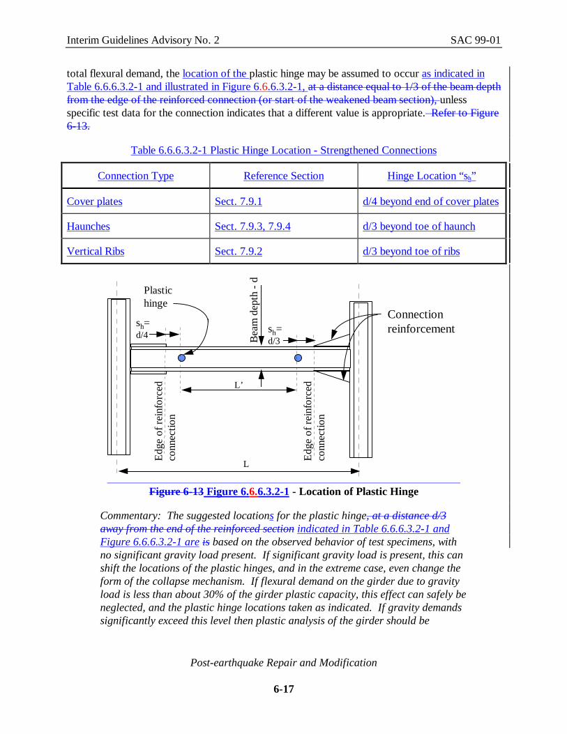
total flexural demand, the location of the plastic hinge may be assumed to occur as indicated inTable 6.6.6.3.2-1 and illustrated in Figure 6.6.6.3.2-1, at a distance equal to 1/3 of the beam depthfrom the edge of the reinforced connection (or start of the weakened beam section), unlessspecific test data for the connection indicates that a different value is appropriate. Refer to Figure6-13.
Table 6.6.6.3.2-1 Plastic Hinge Location - Strengthened Connections
Connection Type Reference Section Hinge Location “sh”
Cover plates Sect. 7.9.1 d/4 beyond end of cover plates
Haunches Sect. 7.9.3, 7.9.4 d/3 beyond toe of haunch
Vertical Ribs Sect. 7.9.2 d/3 beyond toe of ribs
L
Bea
m d
epth
- d
Edge
of r
einf
orce
dco
nnec
tion
Edge
of r
einf
orce
dco
nnec
tion
sh=d/3
L’
Plastichinge
Connectionreinforcementsh=
d/4
Figure 6-13 Figure 6.6.6.3.2-1 - Location of Plastic Hinge
Commentary: The suggested locations for the plastic hinge, at a distance d/3away from the end of the reinforced section indicated in Table 6.6.6.3.2-1 andFigure 6.6.6.3.2-1 are is based on the observed behavior of test specimens, withno significant gravity load present. If significant gravity load is present, this canshift the locations of the plastic hinges, and in the extreme case, even change theform of the collapse mechanism. If flexural demand on the girder due to gravityload is less than about 30% of the girder plastic capacity, this effect can safely beneglected, and the plastic hinge locations taken as indicated. If gravity demandssignificantly exceed this level then plastic analysis of the girder should be

Interim Guidelines Advisory No. 2 SAC 99-01
Post-earthquake Repair and Modification
6-18
performed to determine the appropriate hinge locations. Note that in zones ofhigh seismicity (UBC Zones 3 and 4, and NEHRP Map Areas 6 and 7) gravityloading on the girders of earthquake resisting frames typically has a very smalleffect.
6.6.6.3.3 Determine Probable Plastic Moment at Hinges
The probable value of the plastic moment, Mpr, at the location of the plastic hinges should bedetermined from the equation:
M 0.95 Z Fpr b ya= a (6-1)
M 1.1Z Fpr b ya= (6.6.6.3.3-1)
where: α is a coefficient that accounts for the effects of strain hardening and modelinguncertainty, taken as:
1.1 when qualification testing is performed or calculations are correlated with previous qualification testing
1.3 when design is based on calculations, alone.
Fya is the actual yield stress of the material, as identified from mill test reports. Wheremill test data for the project is not traceable to specific framing elements, theaverage of mill test data for the project for the given shape may be used. Whenmill test data for the project is not available, the value of Fym, fromtable 6-3Table 6.6.6.3-1 may be used.
Zb is the plastic modulus of the section
Commentary: The 1.10.95 factor, in equation 6.6.6.3.3-1, is used to adjustaccount for two effects. First, it is intended to account for the typical differencebetween the yield stress in the beam web, where coupons for mill certificationtests are normally extracted, andto the value in the beam flange. Beam flanges,being comprised of thicker material, typically have somewhat lower yieldstrengths than do beam web material. Second, it is intended toThe factor of 1.1recommended to account for strain hardening, or other sources of strength aboveyield, and agrees fairly well with available test results. It should be noted that the1.1 factor could underestimate the over-strength where significant flangebuckling does not act as the gradual limit on the connection. Nevertheless, the1.1 factor seems a reasonable expectation of over-strength considering thecomplexities involved.
Interim Guidelines Advisory No. 2 SAC 99-01
Post-earthquake Repair and Modification
6-19
Connection designs that result in excessive strength in the girder connectionrelative to the column or excessive demands on the column panel zone are notexpected to produce superior performance. There is a careful balance that mustbe maintained between developing connections that provide for an appropriateallowance for girder overstrength and those that arbitrarily increase connectiondemand in the quest for a “conservative” connection design. The factorssuggested above were chosen in an attempt to achieve this balance, and arbitraryincreases in these values are not recommended.
When the Interim Guidelines were first published, Eq. 6.6.6.3.3-1 included acoefficient, α, intended to account both for the effects of strain hardening andalso for modeling uncertainty when connection designs were based oncalculations as opposed to a specific program of qualification testing. The intentof this modeling uncertainty factor was twofold: to provide additionalconservatism in the design when specific test data for a representative connectionwas not available, and also as an inducement to encourage projects to undertakeconnection qualification testing programs. After the Interim Guidelines had beenin use for some time, it became apparent that this approach was not an effectiveinducement for projects to perform qualification testing, and also that the use ofan overly large value for the α coefficient often resulted in excessively largeconnection reinforcing elements (cover plates, e.g.) and other design features thatdid not appear conducive to good connection behavior. Consequently, it wasdecided to remove this modeling uncertainty factor from the calculation of theprobable strength of an assembly.
6.6.6.3.4 Determine Beam Shear
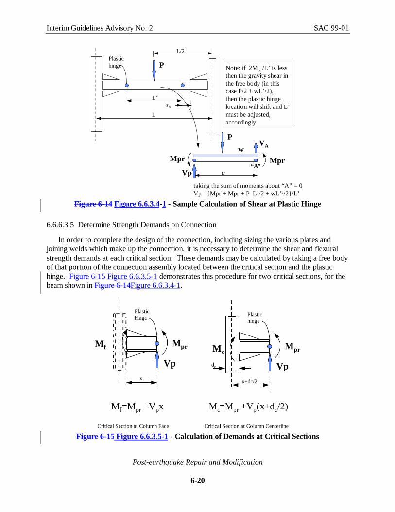
The shear in the beam at the location of the plastic hinge should be determined. A free bodydiagram of that portion of the beam located between plastic hinges is a useful tool for obtainingthe shear at each plastic hinge. Figure 6-14Figure 6.6.3.4-1 provides an example of such acalculation.
Interim Guidelines Advisory No. 2 SAC 99-01
Post-earthquake Repair and Modification
6-20
L
sh
L’
Plastichinge P
L/2
P
Mpr MprL’Vp
taking the sum of moments about “A” = 0Vp ={Mpr + Mpr + P L’/2 + wL’2/2}/L’
“A”
VAw
Note: if 2Mpr /L’ is less then the gravity shear in the free body (in thiscase P/2 + wL’/2),then the plastic hinge location will shift and L’must be adjusted, accordingly
Figure 6-14 Figure 6.6.3.4-1 - Sample Calculation of Shear at Plastic Hinge
6.6.6.3.5 Determine Strength Demands on Connection
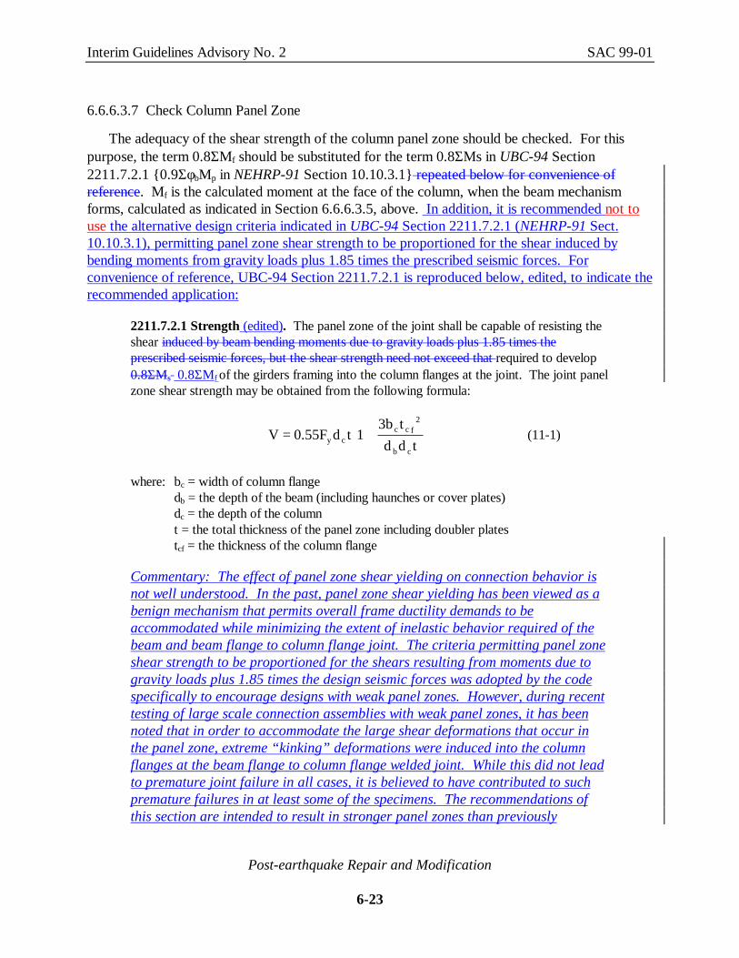
In order to complete the design of the connection, including sizing the various plates andjoining welds which make up the connection, it is necessary to determine the shear and flexuralstrength demands at each critical section. These demands may be calculated by taking a free bodyof that portion of the connection assembly located between the critical section and the plastichinge. Figure 6-15 Figure 6.6.3.5-1 demonstrates this procedure for two critical sections, for thebeam shown in Figure 6-14Figure 6.6.3.4-1.
Plastichinge
Vp
Mpr
Plastichinge
Vp
Mpr
x
Mf
x+dc/2
dc
Mf=Mpr +Vpx
Mc
Mc=Mpr +Vp(x+dc/2)
Critical Section at Column Face Critical Section at Column Centerline
Figure 6-15 Figure 6.6.3.5-1 - Calculation of Demands at Critical Sections

Interim Guidelines Advisory No. 2 SAC 99-01
Post-earthquake Repair and Modification
6-21
Commentary: Each unique connection configuration may have different criticalsections. The vertical plane that passes through the joint between the beamflanges and column (if such joining occurs) will typically define at least one suchcritical section, used for designing the joint of the beam flanges to the column, aswell as evaluating shear demands on the column panel zone. A second criticalsection occurs at the center line of the column. Moments calculated at this pointare used to check weak beam - strong column conditions. Other critical sectionsshould be selected as appropriate to the connection configuration.
6.6.6.3.6 Check for Strong Column - Weak Beam Condition
Buildings which form sidesway mechanisms through the formation of plastic hinges in thebeams can dissipate more energy than buildings that develop mechanisms consisting primarily ofplastic hinges in the columns. Therefore, if an existing building’s original design was such thathinging would occur in the beams rather than the columns, care should be taken not to alter thisbehavior with the addition of connection reinforcement. To determine if the desired strongcolumn - weak beam condition exists, the connection assembly should be checked to determine ifthe following equation is satisfied:
Z (F f ) M 1.0c yc a c− >∑ ∑ (6.6.6.3.6-12)
where: Zc is the plastic modulus of the column section above and below the connectionFyc is the minimum specified yield stress for the column above and belowfa is the axial load in the column above and belowΣMc is the moment calculated at the center of the column in accordance with
Section 6.6.6.3.5 sum of the column moments at the top and bottom of the panel zone, respectively, resulting from the development of the probable beam plastic moments, Mpr, within each beam in the connection.
Commentary: Equation 6.6.6.3.6-12 is based on the building code provisions forstrong column - weak beam design. The building code provisions for evaluatingstrong column - weak beam conditions presume that the flexural stiffness of thecolumns above and below the beam are approximately equal, that the beams willyield at the face of the column, and that the depth of the columns and beams aresmall relative to their respective span lengths. This permits the code to use arelatively simple equation to evaluate strong column - weak beam conditions inwhich the sum of the flexural capacities of columns at a connection are comparedto the sums of the flexural capacities in the beams. The first publication of theInterim Guidelines took this same approach, except that the definition of ΣMc wasmodified to explicitly recognize that because flexural hinging of the beams wouldoccur at a location removed from the face of the column, the moments deliveredby the beams to the connection would be larger than the plastic moment strengthof the beam. In this equation, ΣMc was taken as the sum of the moments at the

Interim Guidelines Advisory No. 2 SAC 99-01
Post-earthquake Repair and Modification
6-22
center of the column, calculated in accordance with the procedures of Sect.6.6.3.5.
This simplified approach is not always appropriate. If non-symmetricalconnection configurations are used, such as a haunch on only the bottom side ofthe beam, this can result in an uneven distribution of stiffness between the twocolumn segments, and premature yielding of the column, either above, or below,the beam-column connection. Also, it was determined that for connectionconfigurations in which the panel zone depth represents a significant fraction ofthe total column height, such as can occur in some haunched and side-platedconnections, the definition of ΣMc contained in the initial printing of theGuidelines could lead to excessive conservatism in determining whether or not astrong column - weak beam condition exists in a structure. Consequently, InterimGuidelines Advisory No. 1 adopted the current definition of ΣMc for use in thisevaluation. This definition requires that the moments in the column, at the topand bottom of the panel zone be determined for the condition when a plastichinge has formed at all beams in the connection. Figure 6.6.6.3.6-1 illustrates amethod for determining this quantity. In such cases, When evaluation indicatesthat a strong column - weak beam condition does not exist, a plastic analysisshould be considered to determine if an undesirable story mechanism is likely toform in the building.
(L-L’)/2
d ph t
h b
Mpr
Vp
Vp
Mpr
Vc
Vc+Vf
Mct
Mcb
assumed point of zero moment
Note:The quantities Mpr, Vp, L, and L’ areas previously identified. Vf is the incremental shear distributedto the column at the floor level.Other quantities are as shown.
Vf
( )[ ] ( )
( )
VM V L L V h d
h d h
M V h
M V V h
M M M
cpr p f b p
b p t
ct c t
cb c f b
c ct cb
=+ − − +
+ +== +
= +
∑
∑
' ) / /2 2
Figure 6.6.6.3.6-1 Calculation of Column Moment for Strong Column Evaluation
Interim Guidelines Advisory No. 2 SAC 99-01
Post-earthquake Repair and Modification
6-23
6.6.6.3.7 Check Column Panel Zone
The adequacy of the shear strength of the column panel zone should be checked. For thispurpose, the term 0.8ΣMf should be substituted for the term 0.8ΣMs in UBC-94 Section2211.7.2.1 {0.9ΣφbMp in NEHRP-91 Section 10.10.3.1} repeated below for convenience ofreference. Mf is the calculated moment at the face of the column, when the beam mechanismforms, calculated as indicated in Section 6.6.6.3.5, above. In addition, it is recommended not touse the alternative design criteria indicated in UBC-94 Section 2211.7.2.1 (NEHRP-91 Sect.10.10.3.1), permitting panel zone shear strength to be proportioned for the shear induced bybending moments from gravity loads plus 1.85 times the prescribed seismic forces. Forconvenience of reference, UBC-94 Section 2211.7.2.1 is reproduced below, edited, to indicate therecommended application:
2211.7.2.1 Strength (edited). The panel zone of the joint shall be capable of resisting theshear induced by beam bending moments due to gravity loads plus 1.85 times theprescribed seismic forces, but the shear strength need not exceed that required to develop0.8ΣMs 0.8ΣMf of the girders framing into the column flanges at the joint. The joint panelzone shear strength may be obtained from the following formula:
V 0.55F d t 13b td d ty c
c c f2
b c
= +
(11-1)
where: bc = width of column flangedb = the depth of the beam (including haunches or cover plates)dc = the depth of the columnt = the total thickness of the panel zone including doubler platestcf = the thickness of the column flange
Commentary: The effect of panel zone shear yielding on connection behavior isnot well understood. In the past, panel zone shear yielding has been viewed as abenign mechanism that permits overall frame ductility demands to beaccommodated while minimizing the extent of inelastic behavior required of thebeam and beam flange to column flange joint. The criteria permitting panel zoneshear strength to be proportioned for the shears resulting from moments due togravity loads plus 1.85 times the design seismic forces was adopted by the codespecifically to encourage designs with weak panel zones. However, during recenttesting of large scale connection assemblies with weak panel zones, it has beennoted that in order to accommodate the large shear deformations that occur inthe panel zone, extreme “kinking” deformations were induced into the columnflanges at the beam flange to column flange welded joint. While this did not leadto premature joint failure in all cases, it is believed to have contributed to suchpremature failures in at least some of the specimens. The recommendations ofthis section are intended to result in stronger panel zones than previously

Interim Guidelines Advisory No. 2 SAC 99-01
Post-earthquake Repair and Modification
6-24
permitted by the code, thereby avoiding potential failures due to this kinkingaction on the column flanges.
6.6.7 Modification Details
There are no modifications to the Guidelines or Commentary of Section 6.6.7 at this time.
6.6.7.1 Haunch at Bottom Flange
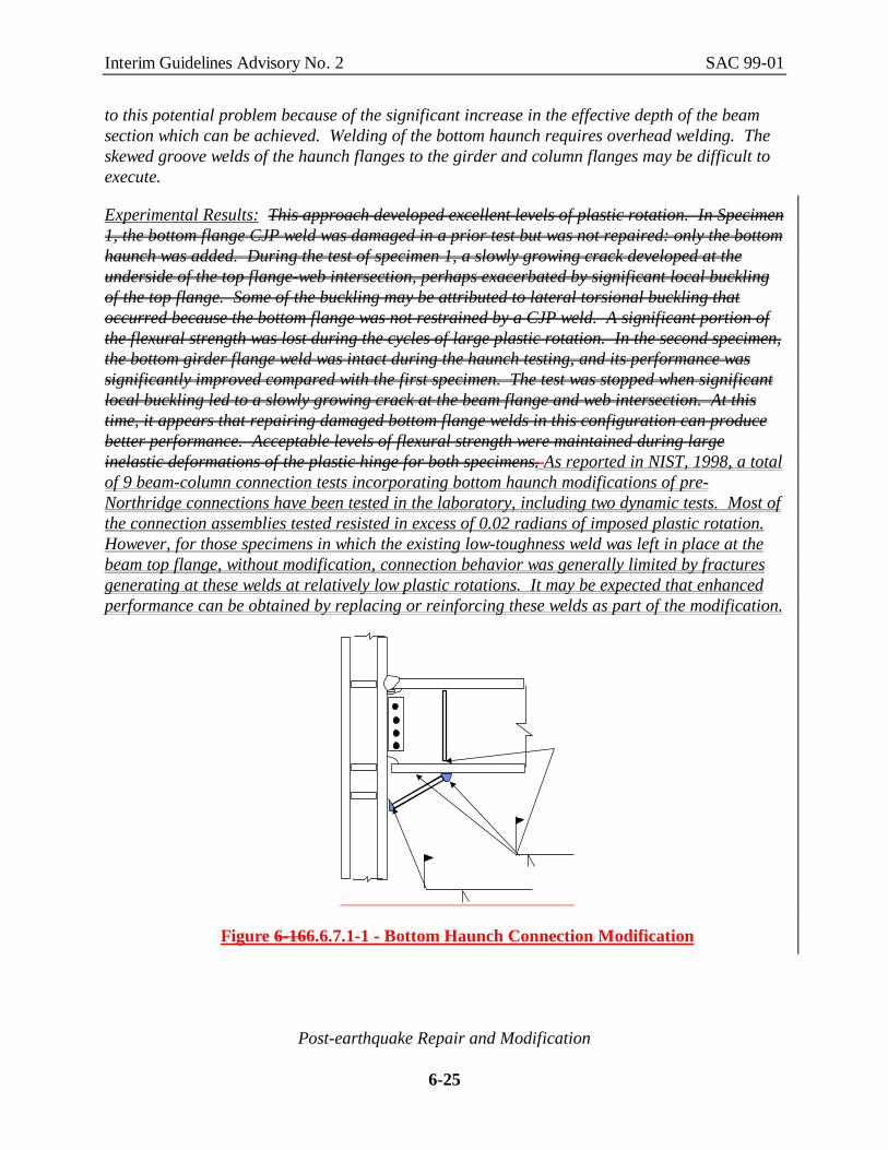
Figure 6-166.6.7.1-1 illustrates the basic configuration for a connection modificationconsisting of the addition of a welded haunch at the bottom beam flange. Several tests of such amodification were conducted by Uang under the SAC phase I project (Uang, 1995). Followingthat work, additional research on the feasibility of improving connection performance with weldedhaunches was conducted under a project that was jointly sponsored by NIST and AISC (NIST,1998). As indicated in the report of that work, the haunched modification improves connectionperformance by altering the basic behavior of the connection. In essence, the haunch creates aprop type support, beneath the beam bottom flange. This both reduces the effective flexuralstresses in the beam at the face of the support, and also greatly reduces the shear that must betransmitted to the column through the beam. Laboratory tests indicate this modification can beeffective when the existing low-toughness welds between the beam bottom flange and column areleft in place, however, more reliable performance is obtained when the top welds are modified. Acomplete procedure for the design of this modification may be found in NIST, 1998. twoalternative configurations of this detail that have been tested (Uang - 1995). The basic concept isto reinforce the connection with the provision of a triangular haunch at the bottom flange. Theintended behavior of both configurations is to shift the plastic hinge from the face of the columnand to reduce the demand on the CJP weld by increasing the effective depth of the section. In onetest, shown on the left of Figure 6-16, the joint between the girder bottom flange and column wascut free, to simulate a condition which might occur if the bottom joint had been damaged, but notrepaired. In a second tested configuration, the bottom flange joint was repaired and the top flangewas replaced with a locally thickened plate, similar to the detail shown in Figure 6-9.
Design Issues: This approach developed acceptable levels of plastic rotation. Acceptable levelsof connection strength were also maintained during large inelastic deformations of the plastichinge. This approach does not require that the top flange be modified, or slab disturbed, unlessother conditions require repair of the top flange, as in the detail on the left of Figure 6-16. Thebottom flange is generally far more accessible than the top flange because a slab does not haveto be removed. In addition, the haunch can be installed at perimeter frames without removal ofthe exterior building cladding. There did not appear to be any appreciable degradation inperformance when the bottom beam flange was not re-welded to the face of the column.Eliminating this additional welding should help reduce the cost of the repair.
Performance is dependent on properly executed complete joint penetration welds at the columnface and at the attachment of the haunch to the girder bottom flange. The joint can be subject tothrough-thickness flaws in the column flange; however, this connection may not be as sensitive
Interim Guidelines Advisory No. 2 SAC 99-01
Post-earthquake Repair and Modification
6-25
to this potential problem because of the significant increase in the effective depth of the beamsection which can be achieved. Welding of the bottom haunch requires overhead welding. Theskewed groove welds of the haunch flanges to the girder and column flanges may be difficult toexecute.
Experimental Results: This approach developed excellent levels of plastic rotation. In Specimen1, the bottom flange CJP weld was damaged in a prior test but was not repaired: only the bottomhaunch was added. During the test of specimen 1, a slowly growing crack developed at theunderside of the top flange-web intersection, perhaps exacerbated by significant local bucklingof the top flange. Some of the buckling may be attributed to lateral torsional buckling thatoccurred because the bottom flange was not restrained by a CJP weld. A significant portion ofthe flexural strength was lost during the cycles of large plastic rotation. In the second specimen,the bottom girder flange weld was intact during the haunch testing, and its performance wassignificantly improved compared with the first specimen. The test was stopped when significantlocal buckling led to a slowly growing crack at the beam flange and web intersection. At thistime, it appears that repairing damaged bottom flange welds in this configuration can producebetter performance. Acceptable levels of flexural strength were maintained during largeinelastic deformations of the plastic hinge for both specimens. As reported in NIST, 1998, a totalof 9 beam-column connection tests incorporating bottom haunch modifications of pre-Northridge connections have been tested in the laboratory, including two dynamic tests. Most ofthe connection assemblies tested resisted in excess of 0.02 radians of imposed plastic rotation.However, for those specimens in which the existing low-toughness weld was left in place at thebeam top flange, without modification, connection behavior was generally limited by fracturesgenerating at these welds at relatively low plastic rotations. It may be expected that enhancedperformance can be obtained by replacing or reinforcing these welds as part of the modification.
Figure 6-166.6.7.1-1 - Bottom Haunch Connection Modification

Interim Guidelines Advisory No. 2 SAC 99-01
Post-earthquake Repair and Modification
6-26
Quantitative Results: No. of specimens tested: 29Girder Size: W30 x 99Column Size: W14 x 176Plastic Rotation achieved-
Specimen 1 UCSD-1R: 0.04 radian (w/o bottom flange weld)Specimen 2 UCSD-3R:0.05 radian (with bottom flange weld)
Specimen UCSD-4R: 0.014 radian (dynamic- limited by test setup)Speciemn UCSD-5R: 0.015 radian (dynamic- limited by test setup)
Girder Size: W36x150Column Size: W14x257Plastic Rotation achieved -
Specimen UCB-RN2: 0.014 radian (no modification of top weld)Specimen UTA-1R: 0.019 radian (partial modification of top weld)Specimen UTA-1RB: 0.028 radian (modified top weld)
Girder Size: W36x150Column Size: W14x455Plastic Rotation achieved-
Specment UTA-NSF4: 0.015 radian (no modification of top weld)
Girder Size: W18x86Column Size: W24x279Plastic Rotation achieved-
Specimen SFCCC-8: 0.035 radian (cover plated top flange)
6.6.7.2 Top and Bottom Haunch
There are no modifications to the Guidelines or Commentary of Section 6.6.7.2 at this time.
6.6.7.3 Cover Plate Sections
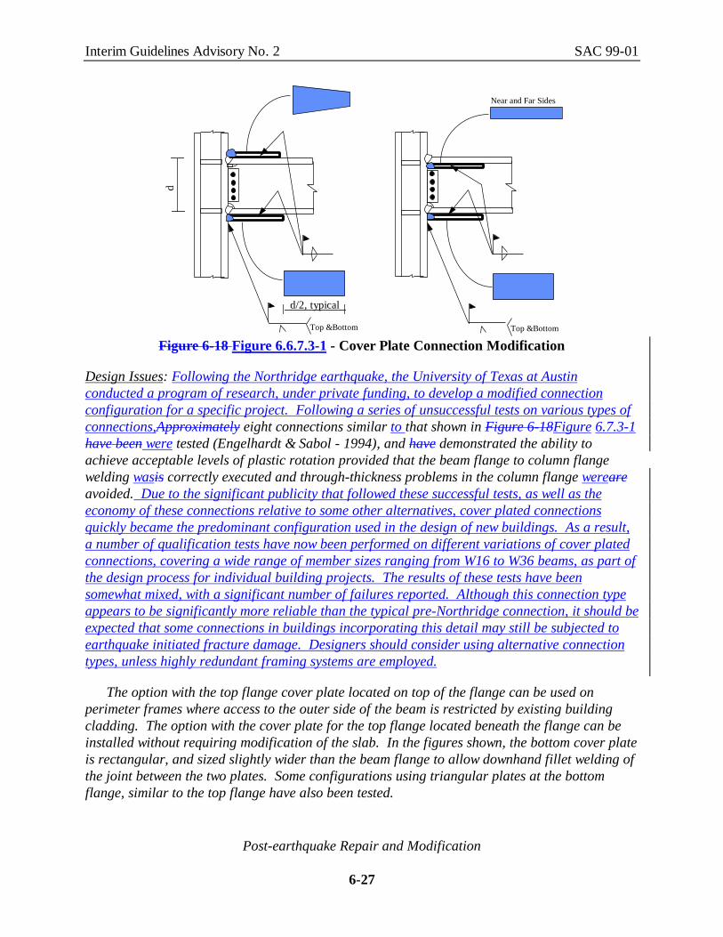
Figure 6.6.7.3-1 Figure 6-18 illustrates the basic configurations of cover plate connections.The assumption behind the cover plate is that it reduces the applied stress demand on the weld atthe column flange and shifts the plastic hinge away from the column face. Only the connectionwith cover plates on the top of the top flange has been tested. There are no quantitative resultsfor cover plates on the bottom side of the top flange, such as might be used in repair. It is likelythat thicker plates would be required where the plates are installed on the underside of the topflange. The implications of this deviation from the tested configuration should be considered.
Interim Guidelines Advisory No. 2 SAC 99-01
Post-earthquake Repair and Modification
6-27
Top &Bottom
Near and Far Sides
Top &Bottom
d
d/2, typical
Figure 6-18 Figure 6.6.7.3-1 - Cover Plate Connection Modification
Design Issues: Following the Northridge earthquake, the University of Texas at Austinconducted a program of research, under private funding, to develop a modified connectionconfiguration for a specific project. Following a series of unsuccessful tests on various types ofconnections,Approximately eight connections similar to that shown in Figure 6-18Figure 6.7.3-1have been were tested (Engelhardt & Sabol - 1994), and have demonstrated the ability toachieve acceptable levels of plastic rotation provided that the beam flange to column flangewelding wasis correctly executed and through-thickness problems in the column flange wereareavoided. Due to the significant publicity that followed these successful tests, as well as theeconomy of these connections relative to some other alternatives, cover plated connectionsquickly became the predominant configuration used in the design of new buildings. As a result,a number of qualification tests have now been performed on different variations of cover platedconnections, covering a wide range of member sizes ranging from W16 to W36 beams, as part ofthe design process for individual building projects. The results of these tests have beensomewhat mixed, with a significant number of failures reported. Although this connection typeappears to be significantly more reliable than the typical pre-Northridge connection, it should beexpected that some connections in buildings incorporating this detail may still be subjected toearthquake initiated fracture damage. Designers should consider using alternative connectiontypes, unless highly redundant framing systems are employed.
The option with the top flange cover plate located on top of the flange can be used onperimeter frames where access to the outer side of the beam is restricted by existing buildingcladding. The option with the cover plate for the top flange located beneath the flange can beinstalled without requiring modification of the slab. In the figures shown, the bottom cover plateis rectangular, and sized slightly wider than the beam flange to allow downhand fillet welding ofthe joint between the two plates. Some configurations using triangular plates at the bottomflange, similar to the top flange have also been tested.
Interim Guidelines Advisory No. 2 SAC 99-01
Post-earthquake Repair and Modification
6-28
Designers using this detail are cautioned to be mindful of not making cover plates so thickthat excessively large welds of the beam flange combination to column flange result. As thecover plates increase in size, the weld size must also increase. Larger welds invariably result ingreater shrinkage stresses and increased potential for cracking prior to actual loading. Inaddition, larger welds will lead to larger heat affected zones in the column flange, a potentiallybrittle area.
Performance is dependent on properly executed girder flange welds. The joint can be subjectto through-thickness failures in the column flange. Access to the top of the top flange requiresdemolition of the existing slab. Access to the bottom of the top flange requires overhead weldingand may be problematic for perimeter frames. Costs are greater than those associated withapproaches that concentrate modifications on the bottom flange
Experimental Results: Six of eight connections tested by the University of Texas at Austin wereable to achieve plastic rotations of at least 0.025 radians, or better. These tests were performedusing heavy column sections which forced nearly all of the plastic deformation into the beamplastic hinge; very little column panel zone deformation occurred. Strength loss at the extremelevels of plastic rotation did not reduce the flexural capacity to less than the plastic momentcapacity of the section based on minimum specified yield strength. One specimen achievedplastic rotations of 0.015 radians when a brittle fracture of the CJP weld (type W2 failure)occurred. This may partially be the result of a weld that was not executed in conformance withthe specified welding procedure specification. The second unsuccessful test specimen achievedplastic rotations of 0.005 radian when a section of the column flange pulled out (type C2failure). The successful tests were terminated either when twisting of the specimen threatened todamage the test setup or the maximum stroke of the loading ram was achieved. Since thecompletion of that testing, a number of additional tests have been performed. Data for 18 tests,including those performed by Engelhardt and referenced above, are in the public domain. Atleast 12 other tests have been performed on behalf of private parties, however, the data fromthese tests are not available. Some of those tests exhibited premature fractures.
Quantitative Results: No. of specimens tested: 18Girder Size: W21 x 68 to W36 x 150Column Size: W12 x 106 to W14 x 455, and 426Plastic Rotation achieved-
6 13 Specimens : >.025 radian to 0.05 radian13 Specimens: 0.005 < θp < 0.0250.015 radian (W2 failure)12 Specimens: 0.005 radian (C2 failure)
6.6.7.4 Upstanding Ribs
There are no modifications to the Guidelines or Commentary of Section 6.6.7.4 at this time.
Interim Guidelines Advisory No. 2 SAC 99-01
Post-earthquake Repair and Modification
6-29
6.6.7.5 Side-Plate Connections
There are no modifications to the Guidelines or Commentary of Section 6.6.7.5 at this time.
6.6.7.6 Bolted Brackets
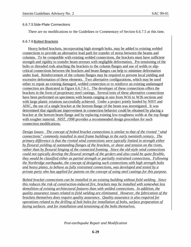
Heavy bolted brackets, incorporating high strength bolts, may be added to existing weldedconnections to provide an alternative load path for transfer of stress between the beams andcolumns. To be compatible with existing welded connections, the brackets must have sufficientstrength and rigidity to transfer beam stresses with negligible deformation. Pre-tensioning of thebolts or threaded rods attaching the brackets to the column flanges and use of welds or slip-critical connections between the brackets and beam flanges can help to minimize deformationunder load. Reinforcement of the column flanges may be required to prevent local yielding andexcessive deformation of these elements. Two alternative configurations, which may be usedeither to repair an existing damaged, welded connection or to reinforce an existing undamagedconnection are illustrated in Figure 6.6.7.6-1. The developer of these connections offers thebrackets in the form of proprietary steel castings. Several tests of these alternative connectionshave been performed on specimens with beams ranging in size from W16 to W36 sections andwith large plastic rotations successfully achieved. Under a project jointly funded by NIST andAISC, the use of a single bracket at the bottom flange of the beam was investigated. It wasdetermined that significant improvement in connection behavior could be obtained by placing abracket at the bottom beam flange and by replacing existing low-toughness welds at the top flangewith tougher material. NIST, 1998 provides a recommended design procedure for suchconnection modifications.
Design Issues: The concept of bolted bracket connections is similar to that of the riveted “windconnections” commonly installed in steel frame buildings in the early twentieth century. Theprimary difference is that the riveted wind connections were typically limited in strength eitherby flexural yielding of outstanding flanges of the brackets, or shear and tension on the rivets,rather than by flexural hinging of the connected framing. Since the old-style wind connectionscould not typically develop the flexural strength of the girders and also could be quite flexible,they would be classified either as partial strength or partially restrained connections. Followingthe Northridge earthquake, the concept of designing such connections with high strength boltsand heavy plates, to behave as fully restrained connections, was developed and tested by aprivate party who has applied for patents on the concept of using steel castings for this purpose.
Bolted bracket connections can be installed in an existing building without field welding. Sincethis reduces the risk of construction-induced fire, brackets may be installed with somewhat lessdemolition of existing architectural features than with welded connections. In addition, thequality assurance issues related to field welding are eliminated. However, the fabrication of thebrackets themselves does require quality assurance. Quality assurance is also required foroperations related to the drilling of bolt holes for installation of bolts, surface preparation offaying surfaces and for installation and tensioning of the bolts themselves.

Interim Guidelines Advisory No. 2 SAC 99-01
Post-earthquake Repair and Modification
6-30
PipePlate
Bolts
High tensilethreaded rod
Bolts
Steelcasting
WARNING: The information presented in this figure is PROPRIETARY. US and ForeignPatents have been applied for. Use of this information is strictly prohibited except as authorizedin writing by the developer. Violators shall be prosecuted in accordance with US and ForeignPatent Intellectual Property Laws.
Figure 6.6.7.6-1 Bolted Bracket Modification
Bolted brackets can be used to repair damaged connections. If damage is limited to the beamflange to column flange welds, the damaged welds should be dressed out by grinding. Anyexisting fractures in base metal should be repaired as indicated in Section 6.3, in order torestore the strength of the damaged members and also to prevent growth of the fractures underapplied stress. Since repairs to base metal typically require cutting and welding, this reducessomewhat the advantages cited above, with regard to avoidance of field welding.
Experimental Results: A series of tests on several different configurations of proprietary heavybolted bracket connections have been performed at Lehigh University (Ksai & Bleiman, 1996) toqualify these connections for use in repair and modification applications. To test repairapplications, brackets were placed only on the bottom beam flange to simulate installations on aconnection where the bottom flange weld in the original connection had failed. In thesespecimens, bottom flange welds were not installed, to approximate the condition of a fullyfractured weld. The top flange welds of these specimens were made with electrodes rated fornotch toughness, to preclude premature failure of the specimens at the top flange. Forspecimens in which brackets were placed at both the top and bottom beam flanges, both weldswere omitted. Acceptable plastic rotations were achieved for each of the specimens tested. Notesting has yet been performed to determine the effectiveness of bolted brackets when applied toan existing undamaged connection with full penetration beam flange to column flange welds withlow toughness or significant defects or discontinuities.
Quantitative Results: No. of specimens tested: 8Girder Size: W16x40 and W36x150Column Size: W12x65 and W14x425Plastic Rotation achieved - 0.05 radians - 0.07 radians

Interim Guidelines Advisory No. 2 SAC 99-01
Post-earthquake Repair and Modification
6-31
This page intentionally left blank