Embed Size (px)
Citation preview
12/20/2011
1
66Optical Amplifiers
Basic ConceptsOptical Amplifier ?
A device which amplifies the optical signal directly without ever changing it to electricity. The light itself is amplified
A laser without feedback, whose gain depends upon the incident signal wavelength and the local beam intensity (being used to create population inversion)Amplifier Gain:
Ratio in decibels of input power to output power
Gain Coefficient (A i di t f th ffi i f lifi )Gain Coefficient: (An indicator of the efficiency of an amplifier)The small signal gain divided by the pump power
Gain Spectrum: Gain vs Wavelength
2
12/20/2011
2
Bandwidth: Range of wavelengths over which the amplifier will operate [the full width at half maximum (FWHM) of the gain spectrum g(ω)]
Amplifier Noise:Added mainly as a result of ASE (Amplified Spontaneous Emission). The noise figure of an amplifier is expressed in decibels and is defined as the ratio of the signal-to-noise ratio (SNR) at the input to the SNR at the output:noise ratio (SNR) at the input to the SNR at the output:
Noise Figure = SNR input /SNR output
3
Polarization SensitivityPolarisation sensitivity is the difference in gain of an input signal in one polarisation to the gain in the orthogonal polarisation
Gain SaturationGain SaturationThis is the point where an increase in input power ceases to result in an increase in output power. All of the pump power is used up already and no more power is availableOptical amplifiers are very different to electronic amplifiers in this respect: When an optical amplifieramplifiers in this respect: When an optical amplifier saturates the overall gain of the amplifier is lessened but there is no distortion of the signalIt is usual to run EDFAs in “Gain Saturation”.
4
12/20/2011
3
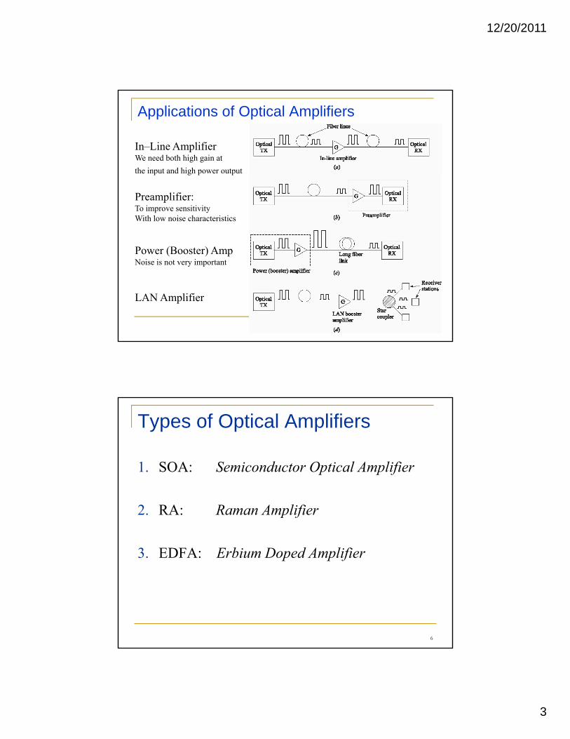
Applications of Optical Amplifiers
In–Line AmplifierWe need both high gain at the input and high power output p g p p
Preamplifier: To improve sensitivityWith low noise characteristics
Power (Booster) Amp
5
Noise is not very important
LAN Amplifier
Types of Optical Amplifiers
1. SOA: Semiconductor Optical Amplifier
2. RA: Raman Amplifier
3. EDFA: Erbium Doped Amplifier
6
12/20/2011
4
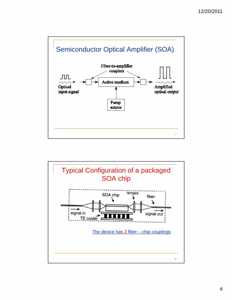
Semiconductor Optical Amplifier (SOA)
7
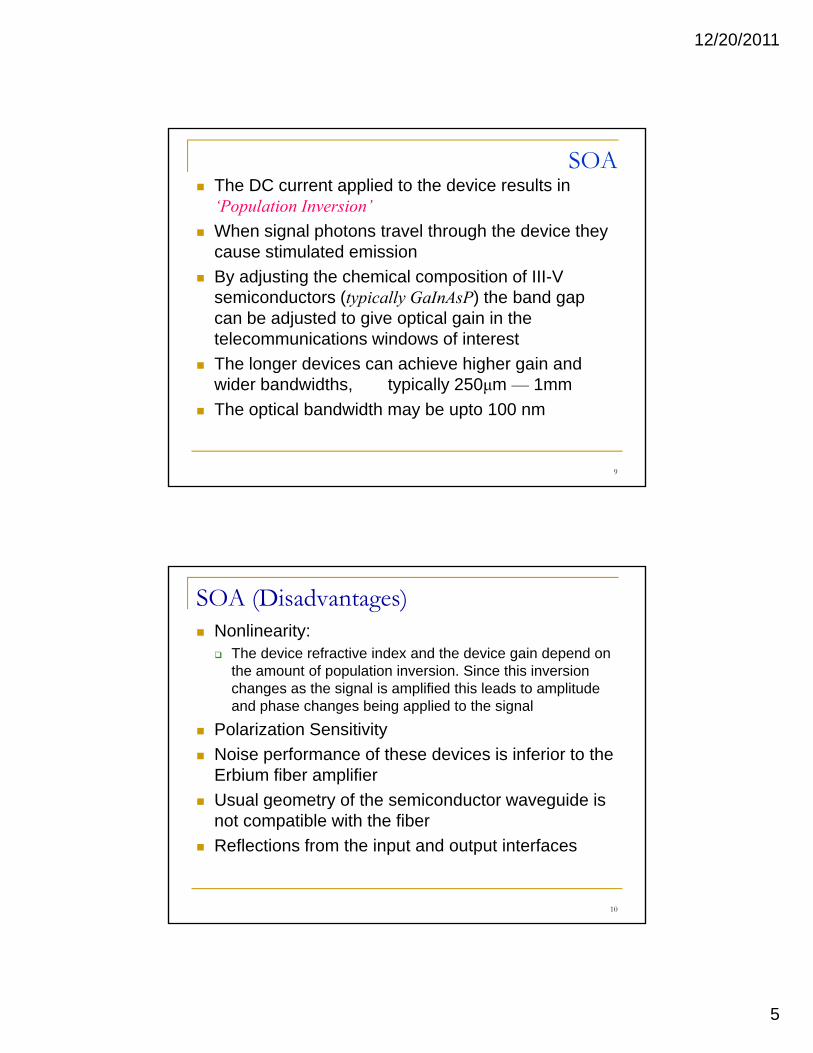
Typical Configuration of a packaged SOA chip
8
The device has 2 fiber – chip couplings
12/20/2011
5
SOAThe DC current applied to the device results in ‘Population Inversion’ When signal photons travel through the device they
ti l t d i icause stimulated emissionBy adjusting the chemical composition of III-V semiconductors (typically GaInAsP) the band gap can be adjusted to give optical gain in the telecommunications windows of interestThe longer devices can achieve higher gain andThe longer devices can achieve higher gain and wider bandwidths, typically 250μm — 1mmThe optical bandwidth may be upto 100 nm
9
SOA (Disadvantages)Nonlinearity:
The device refractive index and the device gain depend on the amount of population inversion. Since this inversion h th i l i lifi d thi l d t lit dchanges as the signal is amplified this leads to amplitude
and phase changes being applied to the signal
Polarization SensitivityNoise performance of these devices is inferior to the Erbium fiber amplifierUsual geometry of the semiconductor waveguide isUsual geometry of the semiconductor waveguide is not compatible with the fiberReflections from the input and output interfaces
10
12/20/2011
6
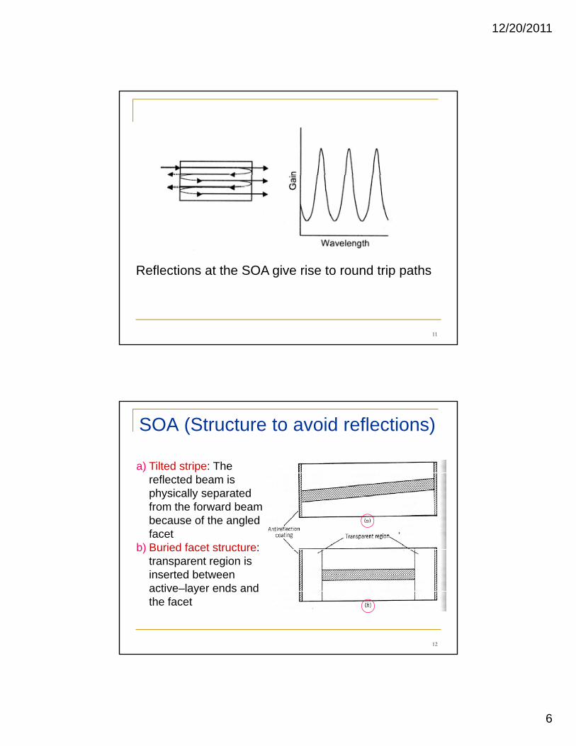
11
Reflections at the SOA give rise to round trip paths
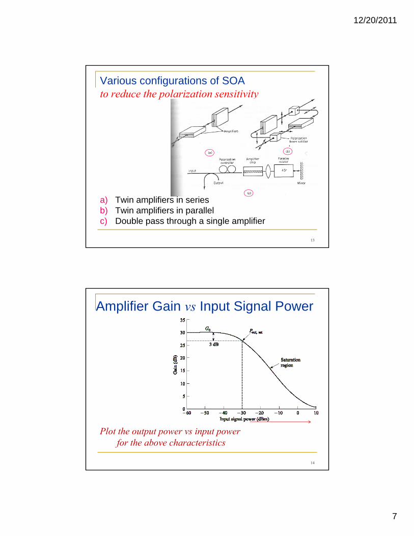
SOA (Structure to avoid reflections)
a) Tilted stripe: The reflected beam is physically separated from the forward beam because of the angled facet
b) Buried facet structure: transparent region is
12
inserted between active–layer ends and the facet
12/20/2011
7
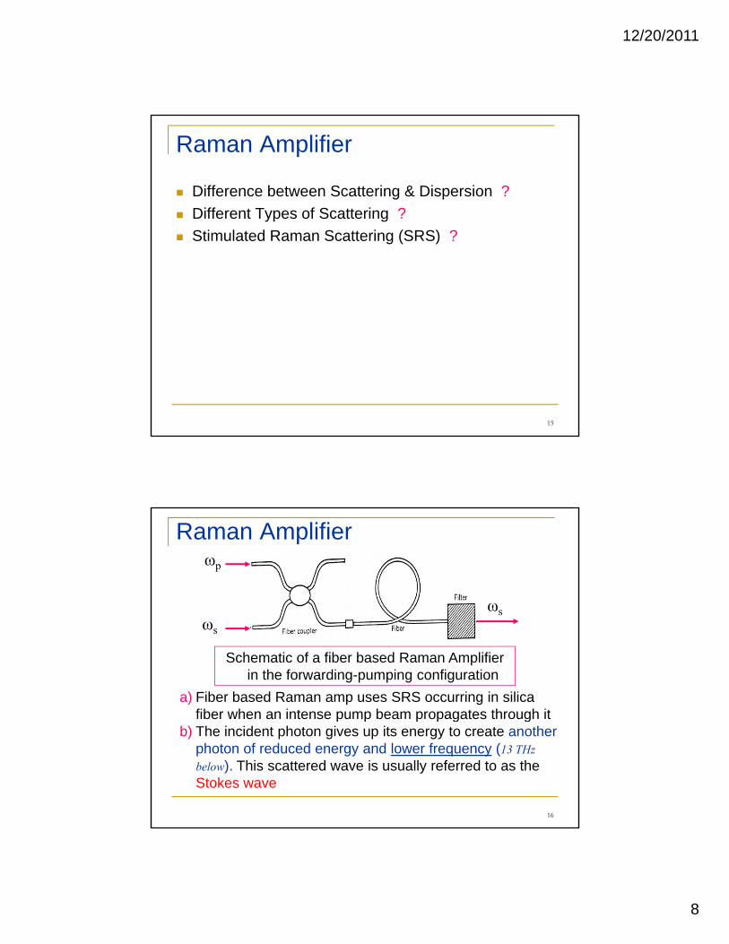
Various configurations of SOA to reduce the polarization sensitivity
a) Twin amplifiers in seriesb) Twin amplifiers in parallelc) Double pass through a single amplifier
13
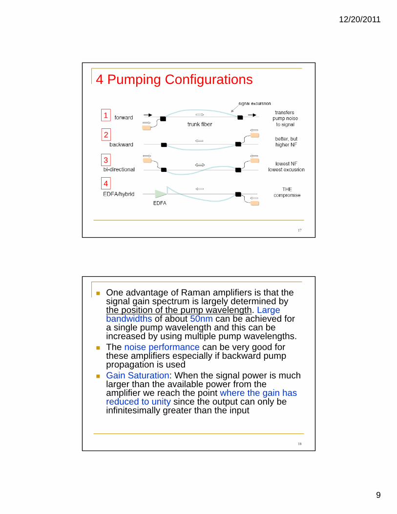
Amplifier Gain vs Input Signal Power
14
Plot the output power vs input power for the above characteristics
12/20/2011
8
Raman Amplifier
Difference between Scattering & Dispersion ?Different Types of Scattering ?Stimulated Raman Scattering (SRS) ?
15
Raman Amplifierωp
ωs
a) Fiber based Raman amp uses SRS occurring in silica fiber when an intense pump beam propagates through it
Schematic of a fiber based Raman Amplifier in the forwarding-pumping configuration
ωs
s
16
p p p p g gb) The incident photon gives up its energy to create another
photon of reduced energy and lower frequency (13 THz below). This scattered wave is usually referred to as the Stokes wave
12/20/2011
9
4 Pumping Configurations
1
2
3
17
4
One advantage of Raman amplifiers is that the signal gain spectrum is largely determined by the position of the pump wavelength. Large bandwidths of about 50nm can be achieved for a single pump wavelength and this can be increased b sing m ltiple p mp a elengthsincreased by using multiple pump wavelengths. The noise performance can be very good for these amplifiers especially if backward pump propagation is used Gain Saturation: When the signal power is much larger than the available power from the amplifier we reach the point where the gain hasamplifier we reach the point where the gain has reduced to unity since the output can only be infinitesimally greater than the input
18
12/20/2011
10
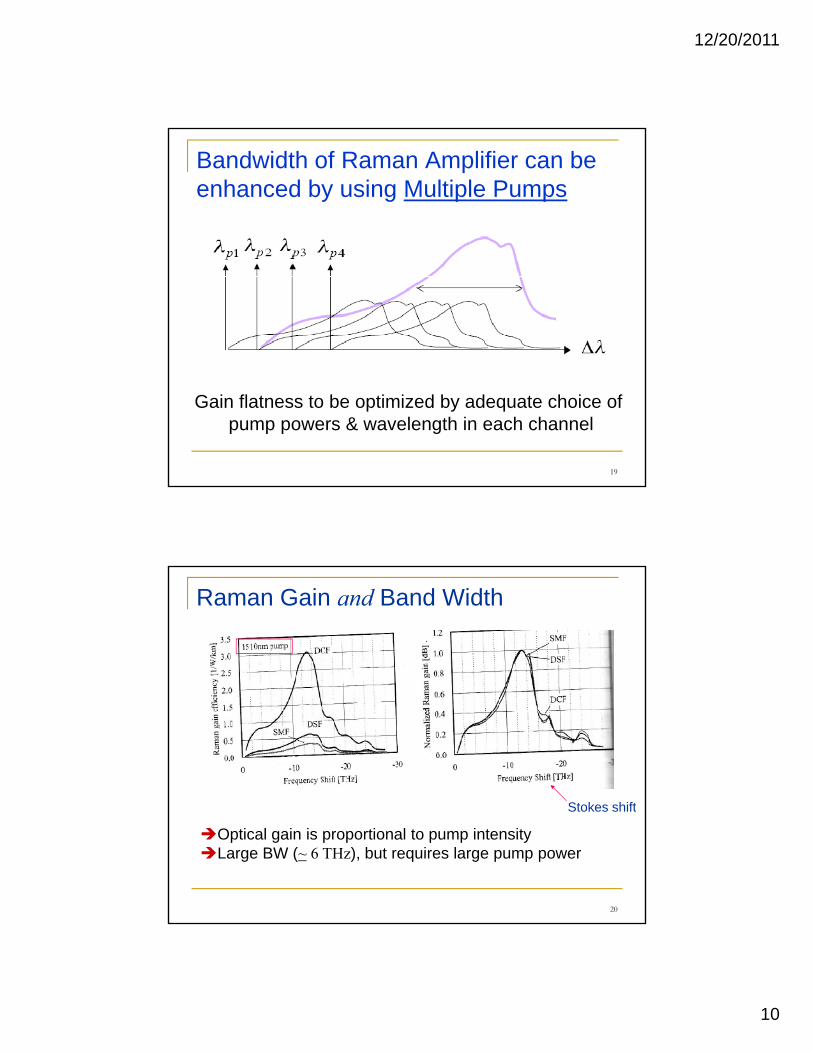
Bandwidth of Raman Amplifier can be enhanced by using Multiple Pumps
19
Gain flatness to be optimized by adequate choice of pump powers & wavelength in each channel
Raman Gain and Band Width
Stokes shift
20
Optical gain is proportional to pump intensityLarge BW (~ 6 THz), but requires large pump power
Stokes shift
12/20/2011
11
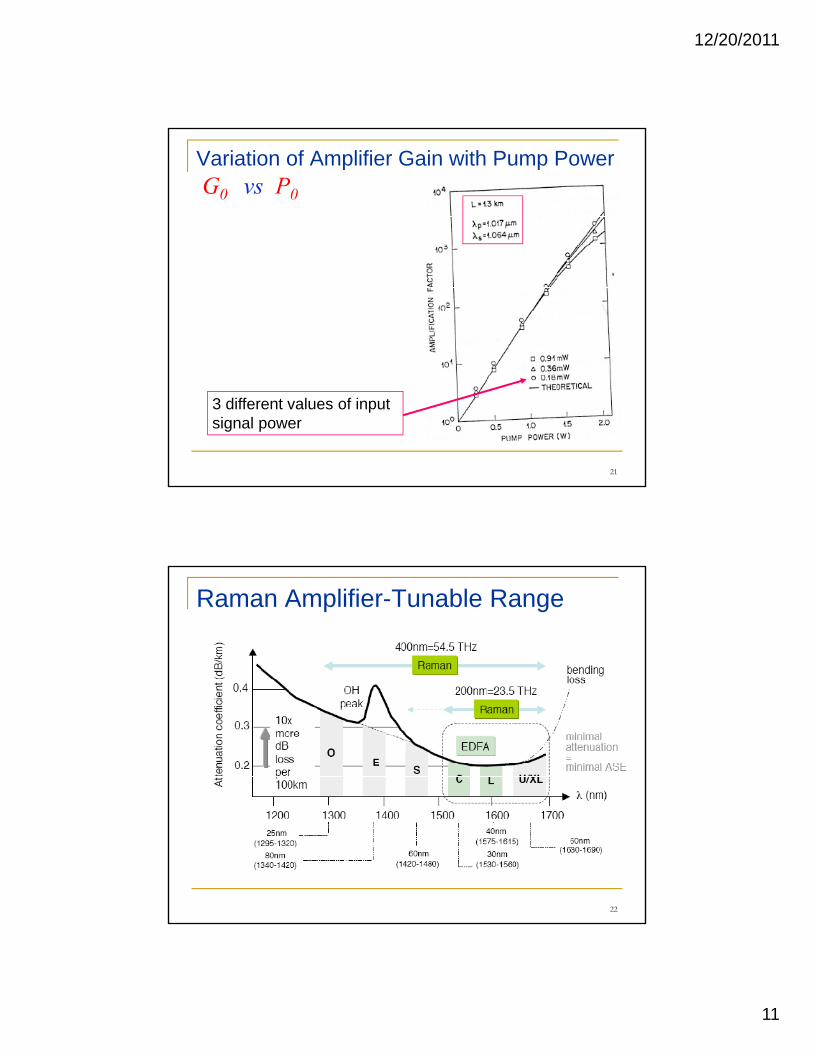
Variation of Amplifier Gain with Pump PowerG0 vs P0
21
3 different values of input signal power
Raman Amplifier-Tunable Range
22
12/20/2011
12
EDFA
23
Erbium Doped Fiber AmplifierEDFA has revolutionized optical communications
All optical and fiber compatibleRequires optical pumping at 980 nm or 1480 nmq p p p gWide bandwidth, 20 ~ 70 nmHigh gain, 20 ~ 40 dB High output power > 200mWBit rate, modulation format and power are wavelength insensitivegLow distortion and low noise (NF < 5dB)Lengths of 10m to 100mLong lifetimes (100 mS)
24
12/20/2011
13
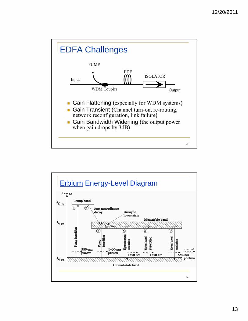
EDFA Challenges
ISOLATOREDF
PUMP
Gain Flattening (especially for WDM systems)Gain Transient (Channel turn-on, re-routing,
Output
Input ISOLATOR
WDM Coupler
( , g,network reconfiguration, link failure)Gain Bandwidth Widening (the output power when gain drops by 3dB)
25
Erbium Energy-Level Diagram
26
12/20/2011
14
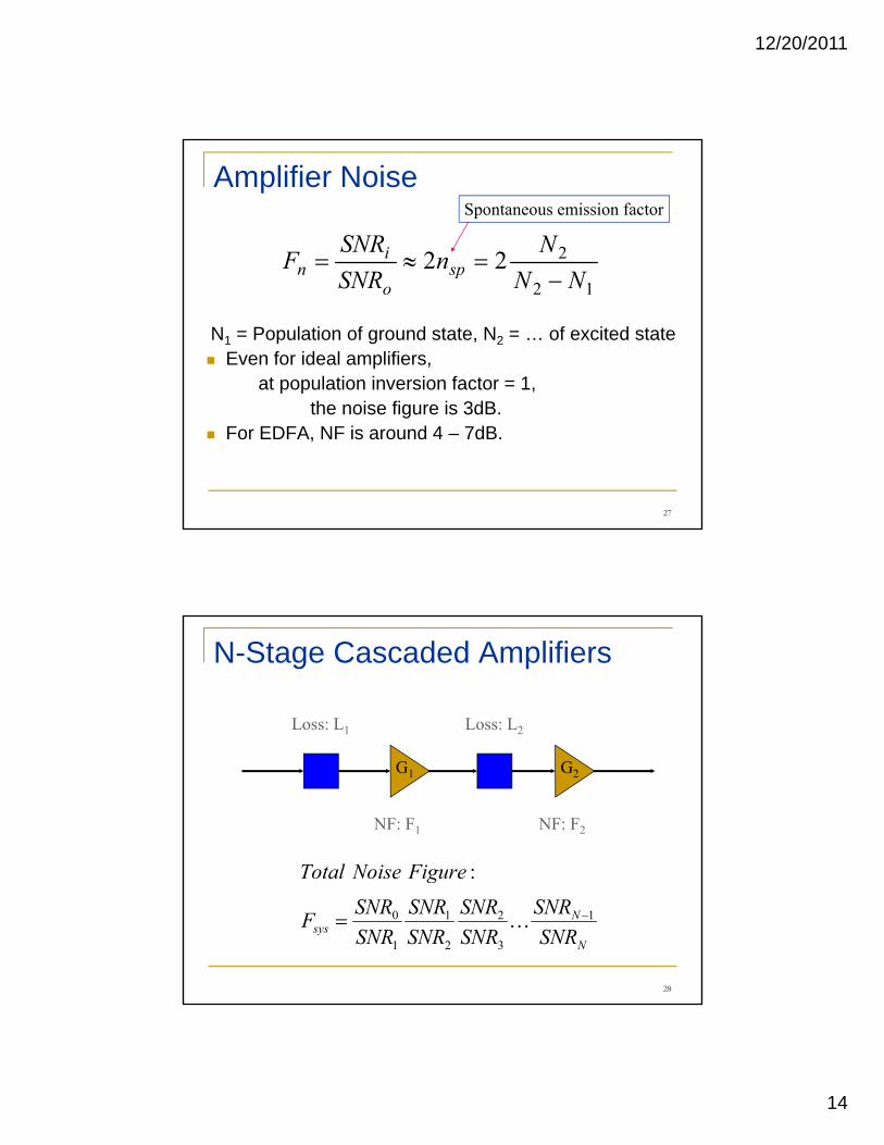
Amplifier Noise
222 NnSNR
F spi
n =≈=
Spontaneous emission factor
N1 = Population of ground state, N2 = … of excited stateEven for ideal amplifiers,
at population inversion factor = 1,
12 NNSNR spo
n −
the noise figure is 3dB.For EDFA, NF is around 4 – 7dB.
27
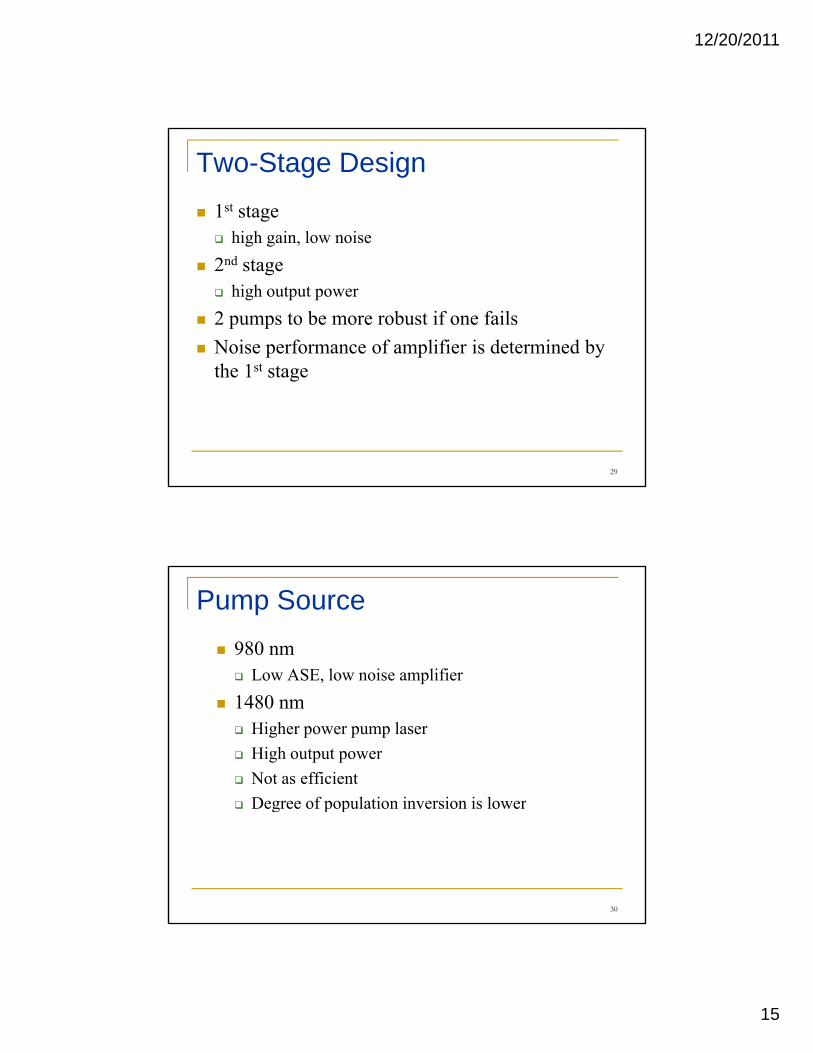
N-Stage Cascaded Amplifiers
Loss: L1 Loss: L2
NF: F1 NF: F2
G1 G2
FigureNoiseTotal :
28
N
Nsys SNR
SNRSNRSNR
SNRSNR
SNRSNRF
FigureNoiseTotal
1
3
2
2
1
1
0
:
−= K
12/20/2011
15
Two-Stage Design1st stage
high gain, low noise2nd stage
high output power2 pumps to be more robust if one failsNoise performance of amplifier is determined by th 1st tthe 1st stage
29
Pump Source980 nm
Low ASE, low noise amplifier1480 nm
Higher power pump laserHigh output powerNot as efficientDegree of population inversion is lowerDegree of population inversion is lower
30
12/20/2011
16
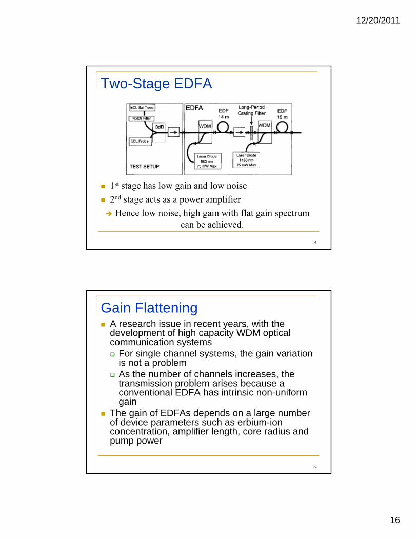
Two-Stage EDFA
1st stage has low gain and low noise1 stage has low gain and low noise2nd stage acts as a power amplifier
Hence low noise, high gain with flat gain spectrum can be achieved.
31
Gain FlatteningA research issue in recent years, with the development of high capacity WDM optical communication systems
F i l h l t th i i tiFor single channel systems, the gain variation is not a problem As the number of channels increases, the transmission problem arises because a conventional EDFA has intrinsic non-uniform gain
The gain of EDFAs depends on a large numberThe gain of EDFAs depends on a large number of device parameters such as erbium-ion concentration, amplifier length, core radius and pump power
32
12/20/2011
17
EDFA design for Gain FlatteningPassive equalization (channel gains cannot be adjusted in a dynamic fashion)
Pre equalize the input signalPre-equalize the input signalAdd dopant: fluoride based EDFABroadband filterHybrid pump
Active equalizationAcousto-Optic Tunable Filter (AOTF)
2–stage design is often used to achieve gain flattening
33
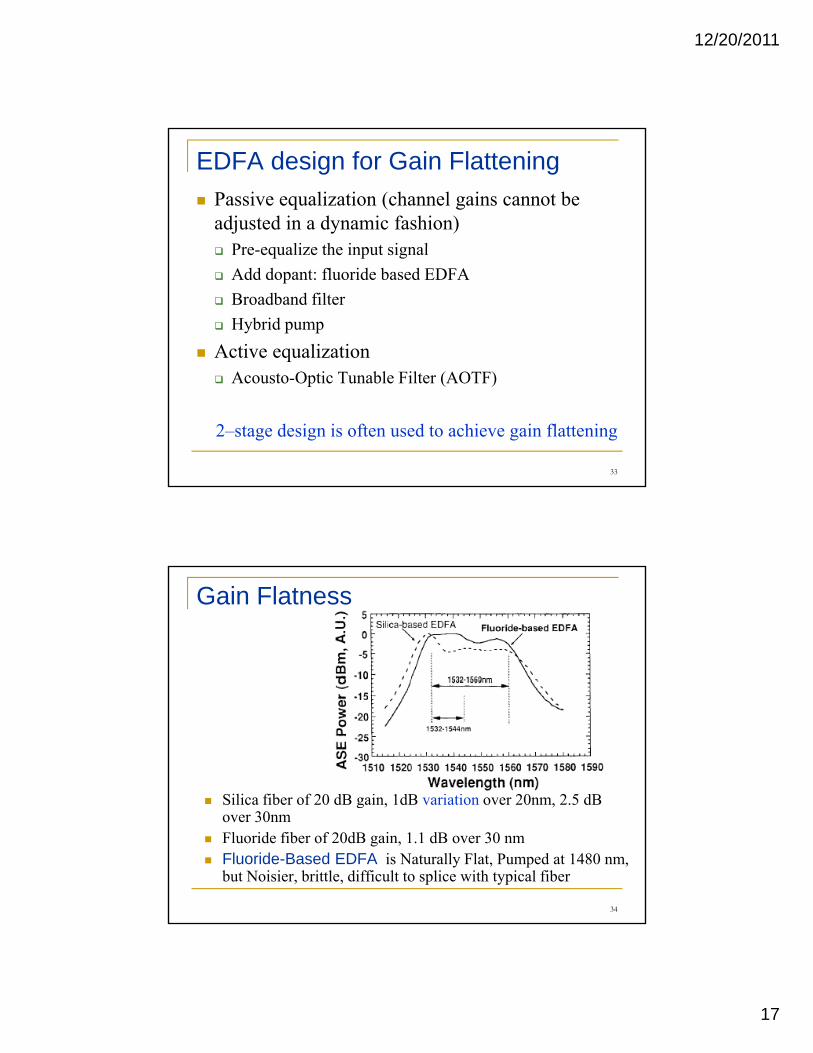
Gain Flatness
Silica fiber of 20 dB gain, 1dB variation over 20nm, 2.5 dB S ca be o 0 d ga , d va at o ove 0 , .5 dover 30nmFluoride fiber of 20dB gain, 1.1 dB over 30 nmFluoride-Based EDFA is Naturally Flat, Pumped at 1480 nm, but Noisier, brittle, difficult to splice with typical fiber
34
12/20/2011
18
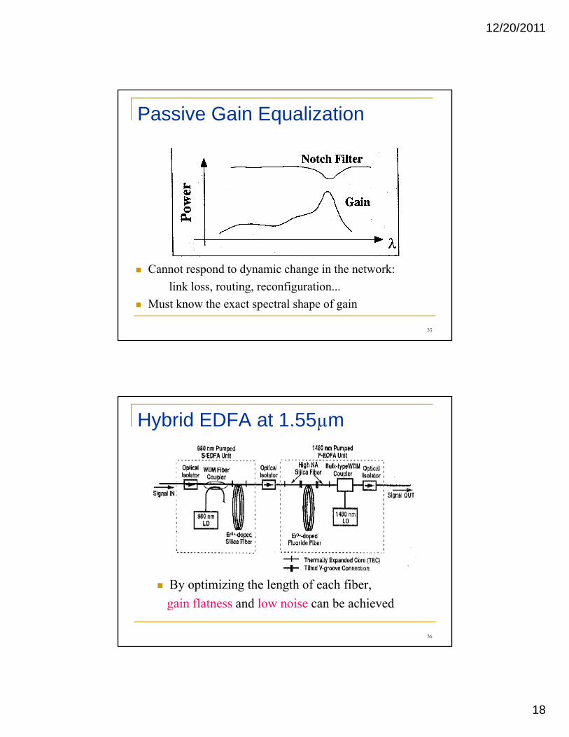
Passive Gain Equalization
Cannot respond to dynamic change in the network: link loss, routing, reconfiguration...
Must know the exact spectral shape of gain
35
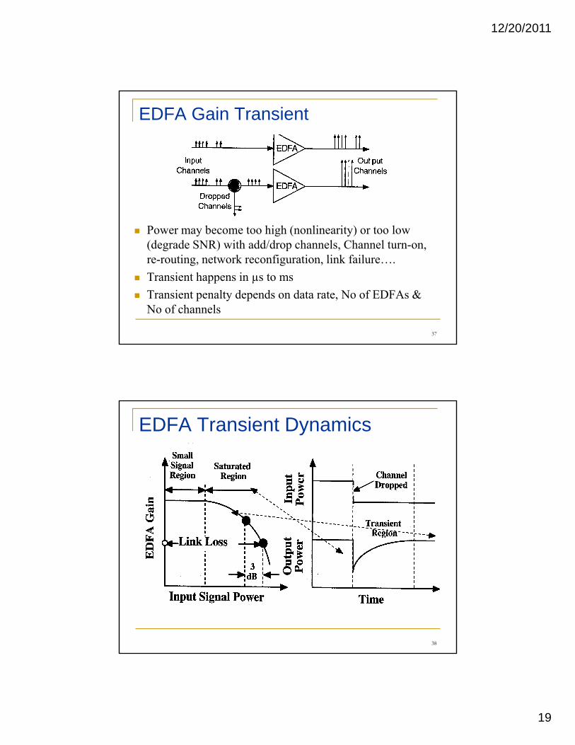
Hybrid EDFA at 1.55µm
By optimizing the length of each fiber, gain flatness and low noise can be achieved
36
12/20/2011
19
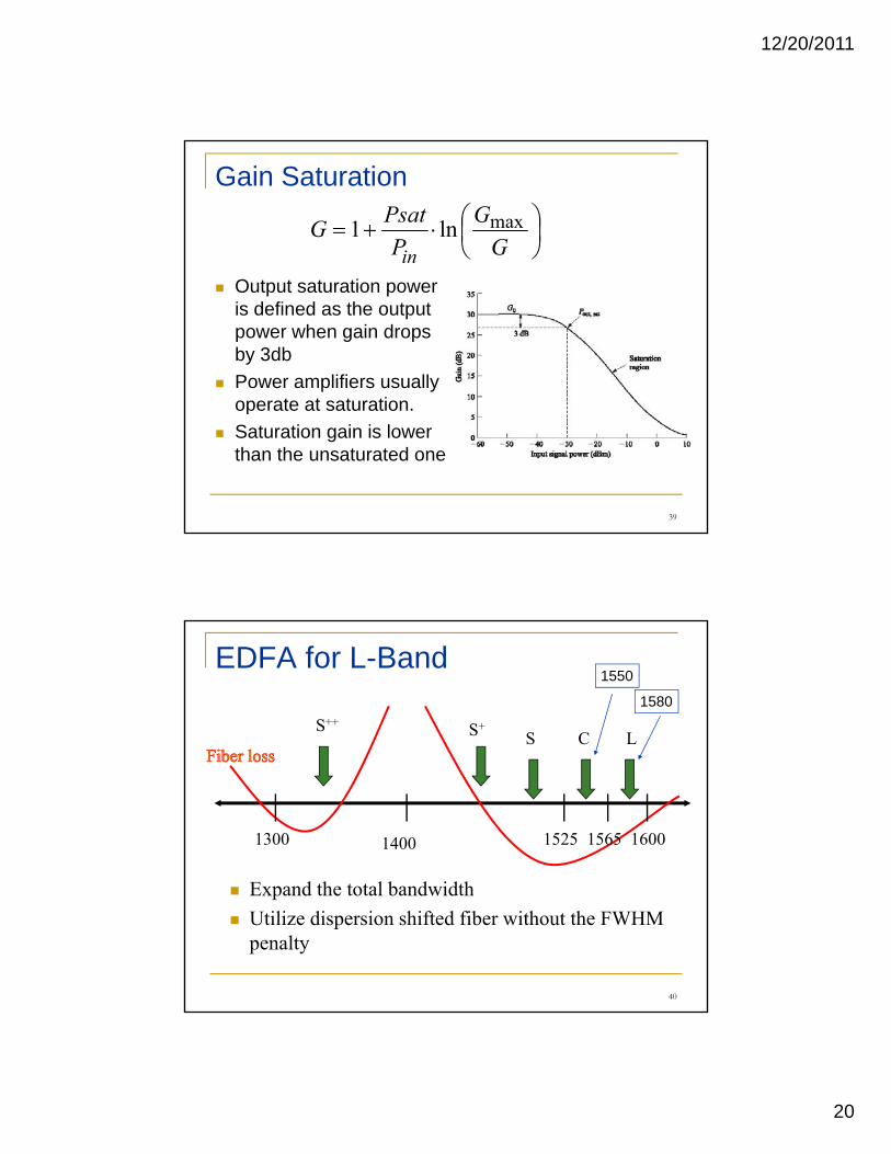
EDFA Gain Transient
Power may become too high (nonlinearity) or too low (degrade SNR) with add/drop channels, Channel turn-on, re routing network reconfiguration link failurere-routing, network reconfiguration, link failure….Transient happens in µs to msTransient penalty depends on data rate, No of EDFAs & No of channels
37
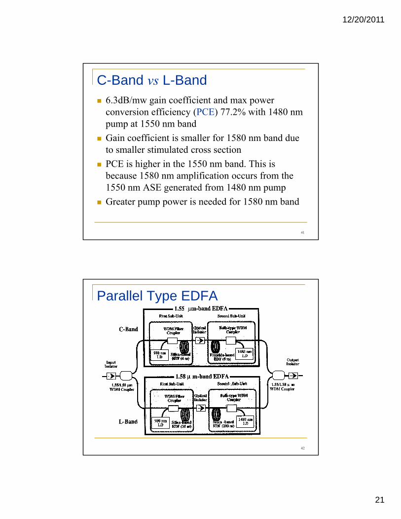
EDFA Transient Dynamics
38
12/20/2011
20
Gain Saturation
⎟⎠⎞
⎜⎝⎛⋅+=
GG
PPsatG
in
maxln1
Output saturation power is defined as the output power when gain drops by 3db Power amplifiers usually operate at saturationoperate at saturation.Saturation gain is lower than the unsaturated one
39
EDFA for L-Band
LCSS+S++
1550
1580
d h l b d id h
1300 1400 1525 1565 1600
Expand the total bandwidthUtilize dispersion shifted fiber without the FWHM penalty
40
12/20/2011
21
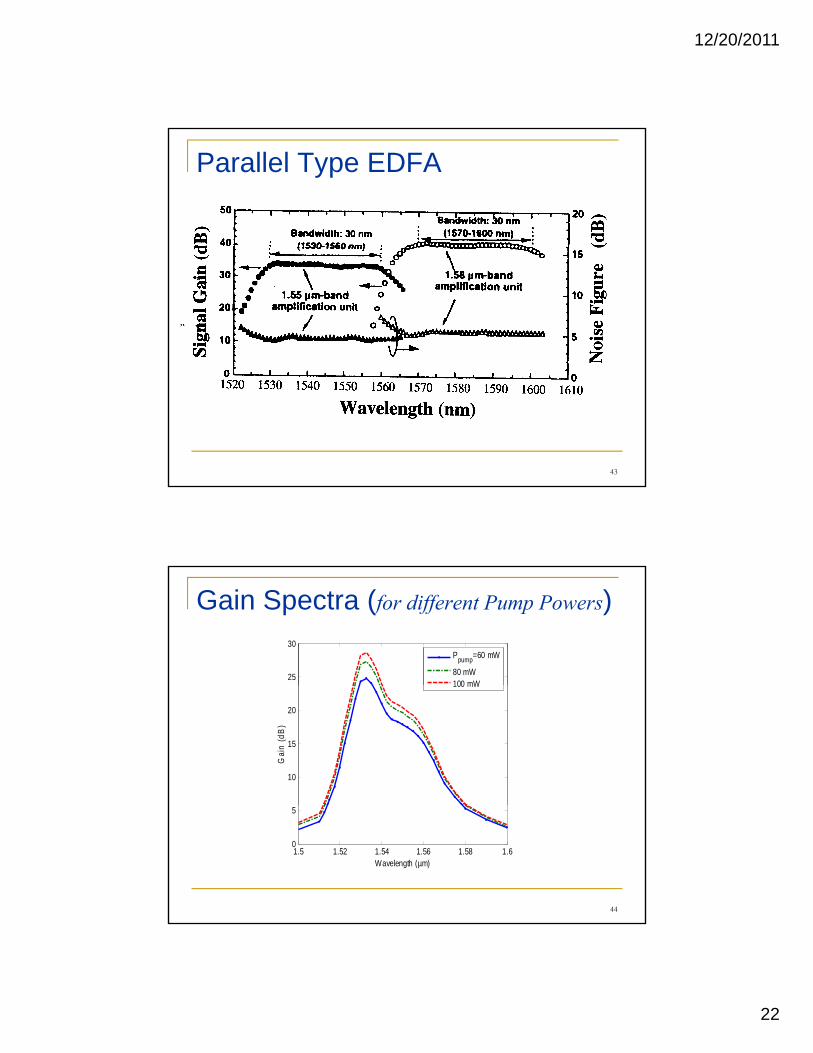
C-Band vs L-Band6.3dB/mw gain coefficient and max power conversion efficiency (PCE) 77.2% with 1480 nm
t 1550 b dpump at 1550 nm bandGain coefficient is smaller for 1580 nm band due to smaller stimulated cross sectionPCE is higher in the 1550 nm band. This is because 1580 nm amplification occurs from the 1550 nm ASE generated from 1480 nm pumpGreater pump power is needed for 1580 nm band
41
Parallel Type EDFA
42
12/20/2011
22
Parallel Type EDFA
43
Gain Spectra (for different Pump Powers)
25
30Ppump=60 mW
80 mW100 mW
10
15
20
Gai
n (d
B)
100 mW
1.5 1.52 1.54 1.56 1.58 1.60
5
Wavelength (µm)
44
12/20/2011
23
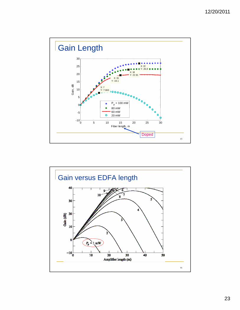
Gain Length
25
30
X: 22Y: 26.8
X: 18
0
5
10
15
20
X: 7Y: 7.663
X: 15Y: 19.1
X: 18Y: 22.91
Gai
n, d
B
Pp = 100 mW
80 mW
45
0 5 10 15 20 25 30-10
-5
Fiber length, m
80 mW60 mW20 mW
Doped
Gain versus EDFA length
46

12/20/2011
24
47