Embed Size (px)
Citation preview
SUSPENSION MODULE
by
Installation and user manual per module
Easy Lift series "MxxxxxxXxxx" or above
User Manual
Page 2 www.landroverpassion.com – www.easylift-eas.com Rev 05
Jun. ’19
Dear Customer,
thank you for choosing Land Rover Passion and for purchasing Easy Lift suspension module. This product has been designed and manufactured respecting the highest standards, enduring high quality performances, safety and user-friendliness.
Land Rover Passion recommends the installation of the module to be carried out by a professional car electrician.
Do you need assistance?
Should you need any assistance, please contact the dealer or Land Rover Passion directly to the following e-mail address:
Warranty:
This product is under warranty to current laws. For any reference, please refer to the page “terms and conditions” on the following website:
http://www.landroverpassion.com/termini-e-condizioni
Product or manual modifications can be made without prior notice. Please check for any new version of this manual on our website www.landroverpassion.com
The contents of this manual are exclusive property of LRP di Massimiliano Berta and cannot be in any way reproduced, either in whole or partially, irrespective of the means used for this purpose, without the prior written permission of LRP.
Any request must be sent by email to [email protected]
User Manual
Page 3 www.landroverpassion.com – www.easylift-eas.com Rev 05
Jun. ’19
LRP di Massimiliano Berta, both in its capacity as a manufacturer and as a distributor, declines any direct and/or indirect responsibility for damage to property and/or injury to people in any way related
to the use of the information contained in this booklet and to the use of Easy Lift, an accessory for which the user is solely and exclusively responsible.
In this regard, LRP di Massimiliano Berta wishes to advise users of the Easy Lift that as the accessory can modify the height values pre-set by the manufacturer of the vehicle for which Easy Lift is intended, it may render it less stable.
Do not drive the vehicle in an unstable status!
LRP di Massimiliano Berta disclaims any liability arising, even indirectly, from negligent and/or imprudent behaviour. An example of such would be an attempt to access - for any reason - the part underneath the vehicle without previously adopting all the available safety measures designed to counteract an accidental variation in height.
LRP di Massimiliano Berta, both in its capacity as manufacturer and distributor, declines any direct and/or indirect liability for damage to property and/or injury to people in any way related to the use of Easy Lift in places open to public traffic.
By purchasing an Easy Lift module, you implicitly accept these terms, and specifically the waiver of liability outlined in this disclaimer, absolving LRP di Massimiliano Berta from any liability arising from the installation and use of Easy Lift.
User Manual
Page 4 www.landroverpassion.com – www.easylift-eas.com Rev 05
Jun. ’19
Summary
1. Safety information ..................................................................... 5
2. Package contents ....................................................................... 6
3. Installation manual .................................................................... 7
3.1. Installation of Bypass wiring harness .......................................... 7
3.2. Installation of controller ............................................................. 9
3.2.1. DISCOVERY 3 L319-04 ................................................................. 9
3.2.2. DISCOVERY 4 L319-10 ............................................................... 11
3.2.3. RANGE ROVER SPORT L320-05 .................................................. 13
3.2.4. RANGE ROVER SPORT L320-10 .................................................. 16
3.3. Correct positioning of the Easy Lift Module ............................... 19
3.4. CALIBRATION PROCEDURES ...................................................... 20
3.4.1. HEIGHTS CALIBRATION ............................................................. 20
3.4.2. SELF-LEVELLING CALIBRATION (VERSION FULL ONLY) ................ 21
4. Operating instructions .............................................................. 23
4.1. Description and general logics of the controller ......................... 23
4.2. Easy Lift versions ...................................................................... 24
4.3. Module configuration ............................................................... 24
4.3.1. heights customization .............................................................. 24
4.3.2. Default program customization ................................................ 25
4.4. STANDARD PROGRAMS – Heights variation .............................. 26
4.5. SPECIAL PROGRAMS (version Full) ............................................ 28
4.5.1. WHEEL ALIGNMENT PROGRAM ................................................ 29
4.5.2. RECOVERY PROGRAM............................................................... 29
4.5.3. EXTRA LOW PROGRAM ............................................................. 29
4.5.4. SELF LEVELLING PROGRAM ....................................................... 30
4.6. Control and visualization through the App ................................ 32
4.7. Neutral button ......................................................................... 32
5. Troubleshooting ....................................................................... 33
User Manual
Page 5 www.landroverpassion.com – www.easylift-eas.com Rev 05
Jun. ’19
1. Safety information
PLEASE READ INSTRUCTIONS CAREFULLY BEFORE STARTING THE INSTALLATION
AND USE OF THE EASY LIFT MODULE
This manual contains very important information about
installation and use of your new suspensions module. Please spend
the necessary time to read it in order to be able to know and
manage the module correctly and at its best.
These symbols you will find into the instructions manual have
the following meaning:
ATTENTION: it indicates an important safety warning and
failing to respect the indications supplied can cause
module malfunction, severe injuries or damage to the
vehicle or equipment.
SUGGESTION: it indicates a suggestion or trick about
using the module to fully benefit of its functionality.
User Manual
Page 6 www.landroverpassion.com – www.easylift-eas.com Rev 05
Jun. ’19
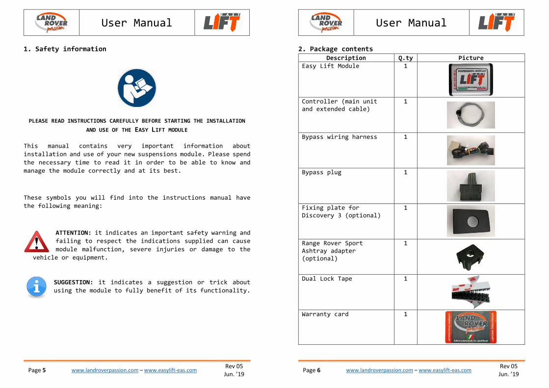
2. Package contents Description Q.ty Picture
Easy Lift Module 1
Controller (main unit
and extended cable)
1
Bypass wiring harness 1
Bypass plug 1
Fixing plate for
Discovery 3 (optional)
1
Range Rover Sport
Ashtray adapter
(optional)
1
Dual Lock Tape 1
Warranty card 1
User Manual
Page 7 www.landroverpassion.com – www.easylift-eas.com Rev 05
Jun. ’19
3. Installation manual
3.1. Installation of Bypass wiring harness
Required tools:
1 Torx T20
1 Screwdriver
1 Socket wrench no. 10
1 Phillips-head screwdriver
Procedure:
o Ensure the vehicle is on a flat surface and that it
can’t move accidentally
o In case of vehicle with automatic transmission,
please select neutral gear “N”
o Disconnect the positive pole of the car battery
o Remove the panel of the steering column by grabbing it on the
top part and pull it towards the seat
o Use the Torx 20 key and remove the control lever used to open
the bonnet
o Use the screwdriver and remove the cover of the footrest. Use
the socket wrench no. 10, unscrew the two bolts inside and
completely remove the footrest
o Remove the plastic bulkhead on the side where the control
lever for the bonnet was placed
o Use the Phillips screwdriver, remove the two screws located
on the front of the panel positioned above the pedals, and
remove it. The panel is fixed by three pins into the sound
deadener coating of the bulkhead behind the pedals and by a
fixing clip toward the central tunnel. Remove it by pulling
gently towards the pedals
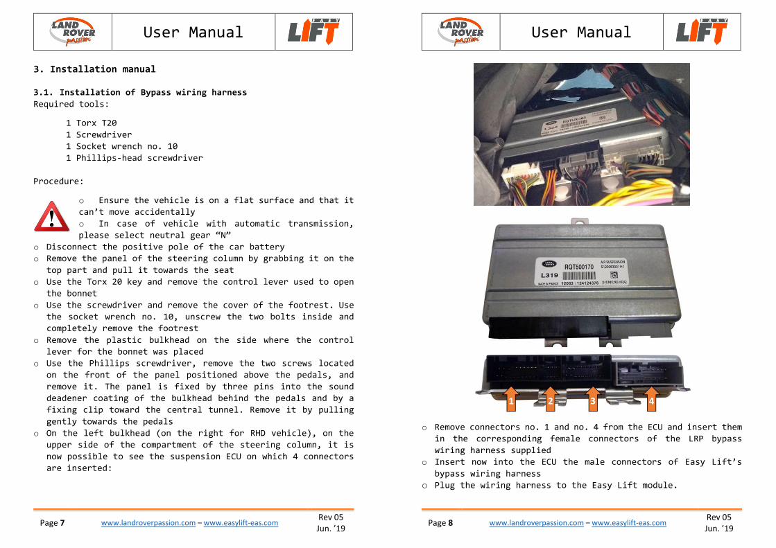
o On the left bulkhead (on the right for RHD vehicle), on the
upper side of the compartment of the steering column, it is
now possible to see the suspension ECU on which 4 connectors
are inserted:
User Manual
Page 8 www.landroverpassion.com – www.easylift-eas.com Rev 05
Jun. ’19
o Remove connectors no. 1 and no. 4 from the ECU and insert them
in the corresponding female connectors of the LRP bypass
wiring harness supplied
o Insert now into the ECU the male connectors of Easy Lift’s
bypass wiring harness
o Plug the wiring harness to the Easy Lift module.
User Manual
Page 9 www.landroverpassion.com – www.easylift-eas.com Rev 05
Jun. ’19
3.2. Installation of controller
Easy Lift can be commanded either by the controller or by Android
or iOS Smartphone (see chapter 4.6). For practicality utilization
purposes, Land Rover Passion advises the complete installation
but, in case you want to simplify and you decide to use the App
exclusively, go directly to the following chapter 4.6.
The controller should always be plugged and unplugged
by taking its connector with your fingers, never by
pulling the cable. When you reassemble the vehicle
please take maximum attention to avoid the cable gets
stuck between the plastics.
You can find the installation procedures below, separately
described for each different vehicle model.
3.2.1. DISCOVERY 3 L319-04
Required tools:
1 Phillips-head screwdriver
Procedure:
o Remove the gear knob, previously placed in Neutral position,
by forcibly pulling it upwards
o Remove the Phillips head screw located in front of the hand-
brake control
o Remove, by pulling it upwards, the plate located behind the
hand-brake control and drill a central 22mm diameter hole, or
replace it with a pre-drilled one (if separately purchased as
optional item).
o Gently lift the cover of the central console by pulling upwards
simultaneously on both external anterior and posterior sides.
Please pay attention to the wirings below: it is not necessary
to unplug them
o Remove the rubber glove box located in front of the gearshift
and the underlying plastic
User Manual
Page
10 www.landroverpassion.com – www.easylift-eas.com
Rev 05
Jun. ’19
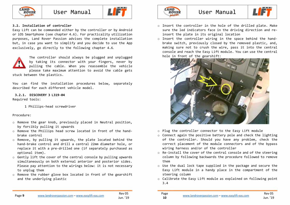
o Insert the controller in the hole of the drilled plate. Make
sure the led indicators face in the driving direction and re-
insert the plate in its original location
o Insert the controller wiring in the space behind the hand-
brake switch, previously closed by the removed plastic, and,
making sure not to crush the wire, pass it into the central
console and reach the Easy Lift module. You can use the central
hole in front of the gearshift:
o Plug the controller connector to the Easy Lift module
o Connect again the positive battery pole and check the lighting
of the controller. Should you have any problem, check the
correct placement of the module connectors and of the bypass
wiring harness and/or of the controller
o Re-install the cover of the central console and of the steering
column by following backwards the procedure followed to remove
them
o Use the dual lock tape supplied in the package and secure the
Easy Lift module in a handy place in the compartment of the
steering column
o Calibrate the Easy Lift module as explained on following point
3.4
User Manual
Page
11 www.landroverpassion.com – www.easylift-eas.com
Rev 05
Jun. ’19
3.2.2. DISCOVERY 4 L319-10
Required tools:
1 Phillips-head screwdriver
Procedure:
o Select Neutral gear position and remove the gear knob by
pulling it upwards
o Remove the cup holder located in the central tunnel and remove
the relative housing by pulling it upwards
o Unscrew the two Phillips-head screws which are located in the
central tunnel, under the cup holder removed
o Remove the little plastic bulkhead in the inner side of the
glove box in the central tunnel
o Open the cover of the glove box or the fridge in the central
tunnel
o Gently lift the cover of the central tunnel by pulling upwards
on both external posterior sides. Pay attention to the wirings
below: it is not necessary to disconnect them
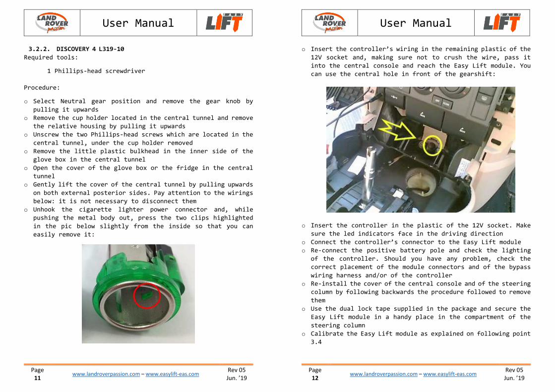
o Unhook the cigarette lighter power connector and, while
pushing the metal body out, press the two clips highlighted
in the pic below slightly from the inside so that you can
easily remove it:
User Manual
Page
12 www.landroverpassion.com – www.easylift-eas.com
Rev 05
Jun. ’19
o Insert the controller’s wiring in the remaining plastic of the
12V socket and, making sure not to crush the wire, pass it
into the central console and reach the Easy Lift module. You
can use the central hole in front of the gearshift:
o Insert the controller in the plastic of the 12V socket. Make
sure the led indicators face in the driving direction
o Connect the controller’s connector to the Easy Lift module
o Re-connect the positive battery pole and check the lighting
of the controller. Should you have any problem, check the
correct placement of the module connectors and of the bypass
wiring harness and/or of the controller
o Re-install the cover of the central console and of the steering
column by following backwards the procedure followed to remove
them
o Use the dual lock tape supplied in the package and secure the
Easy Lift module in a handy place in the compartment of the
steering column
o Calibrate the Easy Lift module as explained on following point
3.4
User Manual
Page
13 www.landroverpassion.com – www.easylift-eas.com
Rev 05
Jun. ’19
3.2.3. RANGE ROVER SPORT L320-05
Required tools:
1 Phillips-head screwdriver
1.Drill with milling drill bit ∅20 mm.
Procedure:
o Remove the “inverted U” shaped car radio frame. In order to
do this, grab the two side parts and pull them towards the
centre of the vehicle
o Remove the two screws located down on the sides of the car
radio
o Select Neutral gear position and remove the gear knob by
pulling it upwards
o Open the cover of the glove box or the fridge in the central
tunnel
o Gently lift the cover of the central tunnel by pulling upwards
on both external posterior sides. Pay attention to the wirings
below: it is not necessary to disconnect them
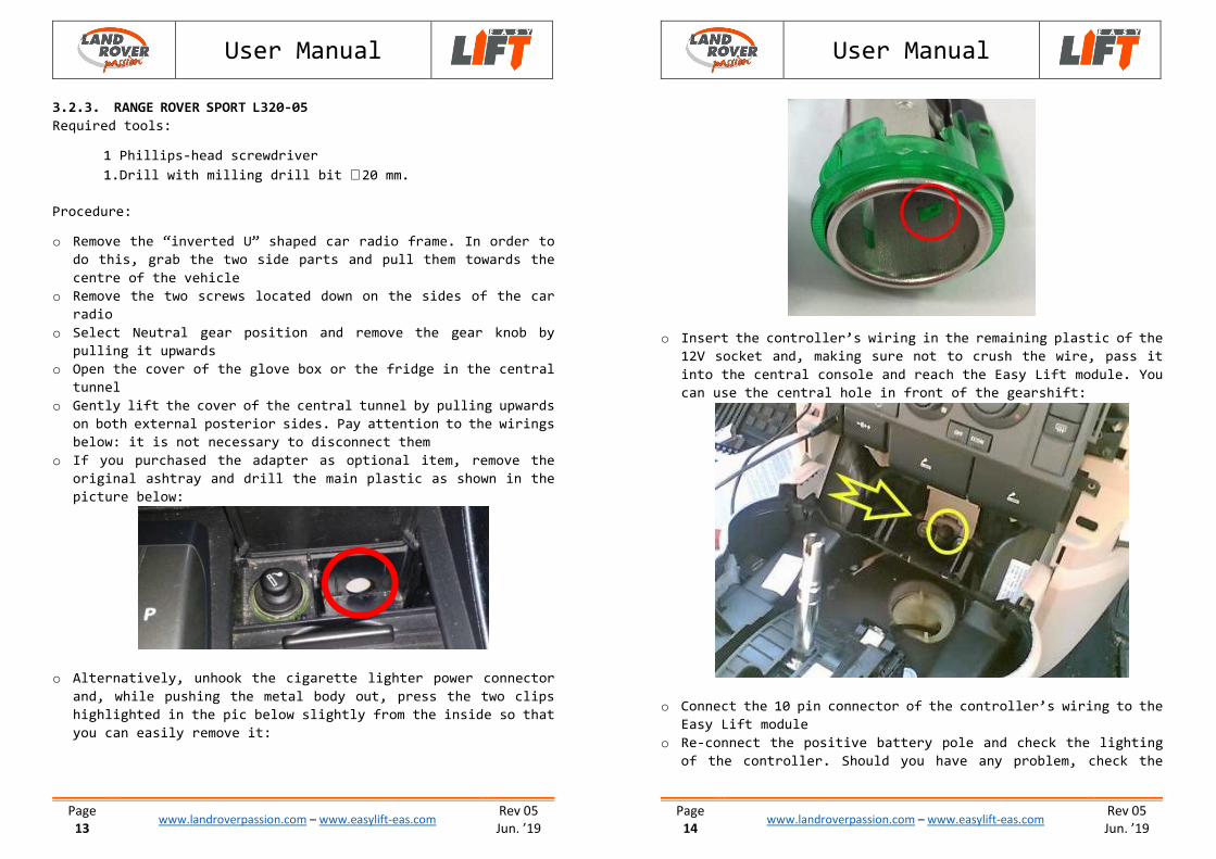
o If you purchased the adapter as optional item, remove the
original ashtray and drill the main plastic as shown in the
picture below:
o Alternatively, unhook the cigarette lighter power connector
and, while pushing the metal body out, press the two clips
highlighted in the pic below slightly from the inside so that
you can easily remove it:
User Manual
Page
14 www.landroverpassion.com – www.easylift-eas.com
Rev 05
Jun. ’19
o Insert the controller’s wiring in the remaining plastic of the
12V socket and, making sure not to crush the wire, pass it
into the central console and reach the Easy Lift module. You
can use the central hole in front of the gearshift:
o Connect the 10 pin connector of the controller’s wiring to the
Easy Lift module
o Re-connect the positive battery pole and check the lighting
of the controller. Should you have any problem, check the

User Manual
Page
15 www.landroverpassion.com – www.easylift-eas.com
Rev 05
Jun. ’19
correct placement of the module’s connectors and of the bypass
wiring harness and/or of the controller
o Re-install the cover of the central console and of the steering
column by following backwards the procedure followed to remove
them
o Use the dual lock tape supplied in the package and secure the
Easy Lift module in a handy place in the compartment of the
steering column
o Calibrate the Easy Lift module as explained on following point
3.4
User Manual
Page
16 www.landroverpassion.com – www.easylift-eas.com
Rev 05
Jun. ’19
3.2.4. RANGE ROVER SPORT L320-10
Required tools:
1 Phillips-head screwdriver
1 Plastic lever
1.Drill with milling drill bit ∅20 mm
Procedure:
o Use the plastic lever and remove the frame of the CD slot
o Remove the two screws located down, laterally, inside the slot
just opened
o Select Neutral gear position and remove the gear knob by
pulling it upwards
o Open the cover of the glove box or the fridge in the central
tunnel
o Gently lift the cover of the central tunnel by pulling upwards
on both external posterior sides. Pay attention to the wirings
below: it is not necessary to disconnect them
o If you purchased the adapter as optional item, remove the
original ashtray and drill the main plastic as shown in the
picture below :
o Alternatively, unhook the cigarette lighter power connector
and, while pushing the metal body out, press the two clips
highlighted in the pic below slightly from the inside so that
you can easily remove it:
User Manual
Page
17 www.landroverpassion.com – www.easylift-eas.com
Rev 05
Jun. ’19
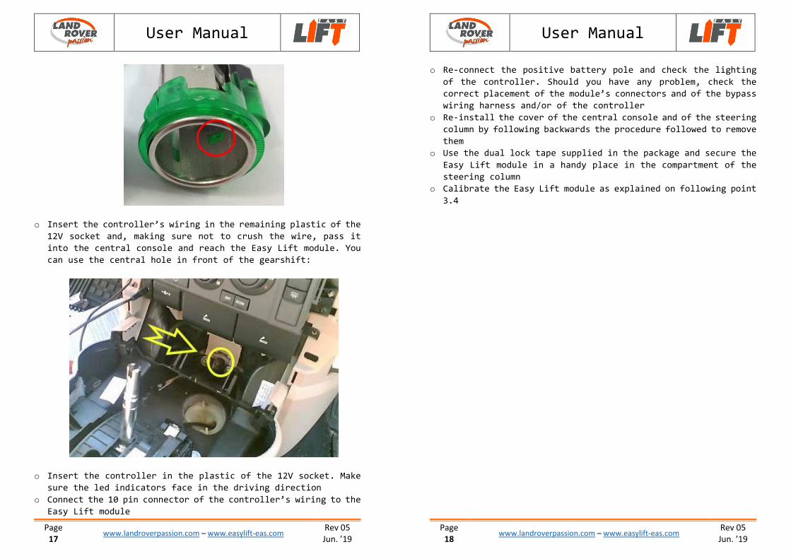
o Insert the controller’s wiring in the remaining plastic of the
12V socket and, making sure not to crush the wire, pass it
into the central console and reach the Easy Lift module. You
can use the central hole in front of the gearshift:
o Insert the controller in the plastic of the 12V socket. Make
sure the led indicators face in the driving direction
o Connect the 10 pin connector of the controller’s wiring to the
Easy Lift module
User Manual
Page
18 www.landroverpassion.com – www.easylift-eas.com
Rev 05
Jun. ’19
o Re-connect the positive battery pole and check the lighting
of the controller. Should you have any problem, check the
correct placement of the module’s connectors and of the bypass
wiring harness and/or of the controller
o Re-install the cover of the central console and of the steering
column by following backwards the procedure followed to remove
them
o Use the dual lock tape supplied in the package and secure the
Easy Lift module in a handy place in the compartment of the
steering column
o Calibrate the Easy Lift module as explained on following point
3.4
User Manual
Page
19 www.landroverpassion.com – www.easylift-eas.com
Rev 05
Jun. ’19
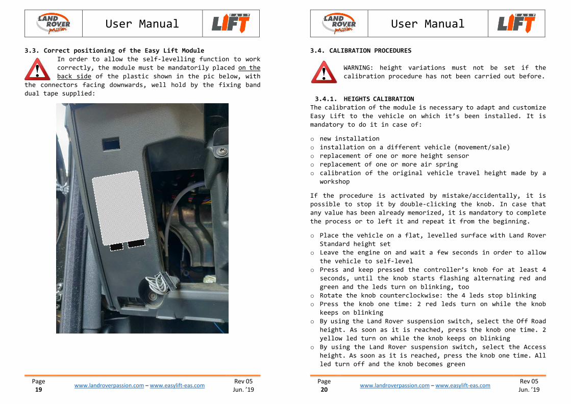
3.3. Correct positioning of the Easy Lift Module
In order to allow the self-levelling function to work
correctly, the module must be mandatorily placed on the
back side of the plastic shown in the pic below, with
the connectors facing downwards, well hold by the fixing band
dual tape supplied:
User Manual
Page
20 www.landroverpassion.com – www.easylift-eas.com
Rev 05
Jun. ’19
3.4. CALIBRATION PROCEDURES
WARNING: height variations must not be set if the
calibration procedure has not been carried out before.
3.4.1. HEIGHTS CALIBRATION
The calibration of the module is necessary to adapt and customize
Easy Lift to the vehicle on which it’s been installed. It is
mandatory to do it in case of:
o new installation
o installation on a different vehicle (movement/sale)
o replacement of one or more height sensor
o replacement of one or more air spring
o calibration of the original vehicle travel height made by a
workshop
If the procedure is activated by mistake/accidentally, it is
possible to stop it by double-clicking the knob. In case that
any value has been already memorized, it is mandatory to complete
the process or to left it and repeat it from the beginning.
o Place the vehicle on a flat, levelled surface with Land Rover
Standard height set
o Leave the engine on and wait a few seconds in order to allow
the vehicle to self-level
o Press and keep pressed the controller’s knob for at least 4
seconds, until the knob starts flashing alternating red and
green and the leds turn on blinking, too
o Rotate the knob counterclockwise: the 4 leds stop blinking
o Press the knob one time: 2 red leds turn on while the knob
keeps on blinking
o By using the Land Rover suspension switch, select the Off Road
height. As soon as it is reached, press the knob one time. 2
yellow led turn on while the knob keeps on blinking
o By using the Land Rover suspension switch, select the Access
height. As soon as it is reached, press the knob one time. All
led turn off and the knob becomes green
User Manual
Page
21 www.landroverpassion.com – www.easylift-eas.com
Rev 05
Jun. ’19
o By using the Land Rover suspension switch, select the Standard
height
o Turn off and then turn on again the engine
The calibration process is now completed and the module is ready
to use.
Once the heights calibration procedure is completed the
module is automatically set to correctly work with the
specifics of the vehicle on which it’s been installed.
Should one move it to another vehicle, only a new calibration
process will be needed to adapt the module to the new car.
The heights variations requested to set the calibration
will consume the content of the air reservoir. Should
you request a rapid height variation without allowing
the vehicle the necessary time to refill the air
reservoir, the following requested variations may take a little
more time to completely set up.
3.4.2. SELF-LEVELLING CALIBRATION (VERSION FULL ONLY)
The levelling sensor calibration is required to memorize the
longitudinal and transversal position of the vehicle: this is
the reference value that Easy Lift will restore when the
levelling function is activated. The calibration has to be set
mandatorily in case of:
o First installation
o Installation on a different vehicle (moving/sale)
o change of position, even if minimal, of the principal Easy
Lift unit compared to the position where it was placed when
the previous calibration had been set
If activated by mistake/accidentally, it’s possible to stop the
procedure by double-clicking.
o Position the vehicle on a flat, levelled surface, with Land
Rover Standard height set
User Manual
Page
22 www.landroverpassion.com – www.easylift-eas.com
Rev 05
Jun. ’19
o Leave the engine on and wait a few seconds in order to allow
the car to self-level
o Press and keep pressed the controller’s knob for 4 seconds,
until the knob starts flashing alternating red and green and
the leds turn on blinking, too
o Rotate the knob clockwise: the 4 leds start an alternating
flashing
o Press the knob once: during the memorizing phase of the
position, 2 leds will remain steadily turned on and the knob
will flash in red
Once the procedure is completed, the module will return
automatically in “Neutral” setting.
The better calibration is done, the better will be the
levelling of the vehicle. It is fundamental then to
verify that none of the wheels is higher or lower compared
to the others, for example owing to holes in the surface or
evident asperities/imperfections of the ground. If these
conditions are respected, if wanted it is possible to calibrate
the vehicle even if it’s not placed on an horizontal surface. By
doing so it will so be possible to choose a different
inclination, for example for a more comfortable sleeping position
following your own preferences, for example with the head side
slightly higher.
In case of purchase of the Plus or Lite version of the
module, it is possible to buy the upgrade to a higher
version in a following moment. Please contact us via e-
mail at [email protected]
User Manual
Page
23 www.landroverpassion.com – www.easylift-eas.com
Rev 05
Jun. ’19
4. Operating instructions
4.1. Description and general logics of the controller
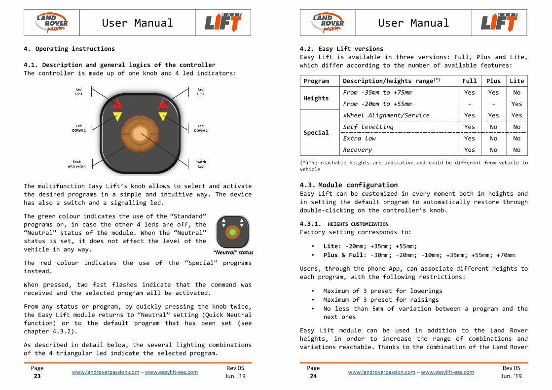
The controller is made up of one knob and 4 led indicators:
The multifunction Easy Lift’s knob allows to select and activate
the desired programs in a simple and intuitive way. The device
has also a switch and a signalling led.
The green colour indicates the use of the “Standard”
programs or, in case the other 4 leds are off, the
“Neutral” status of the module. When the “Neutral”
status is set, it does not affect the level of the
vehicle in any way.
The red colour indicates the use of the “Special” programs
instead.
When pressed, two fast flashes indicate that the command was
received and the selected program will be activated.
From any status or program, by quickly pressing the knob twice,
the Easy Lift module returns to “Neutral” setting (Quick Neutral
function) or to the default program that has been set (see
chapter 4.3.2).
As described in detail below, the several lighting combinations
of the 4 triangular led indicate the selected program.
“Neutral” status
User Manual
Page
24 www.landroverpassion.com – www.easylift-eas.com
Rev 05
Jun. ’19
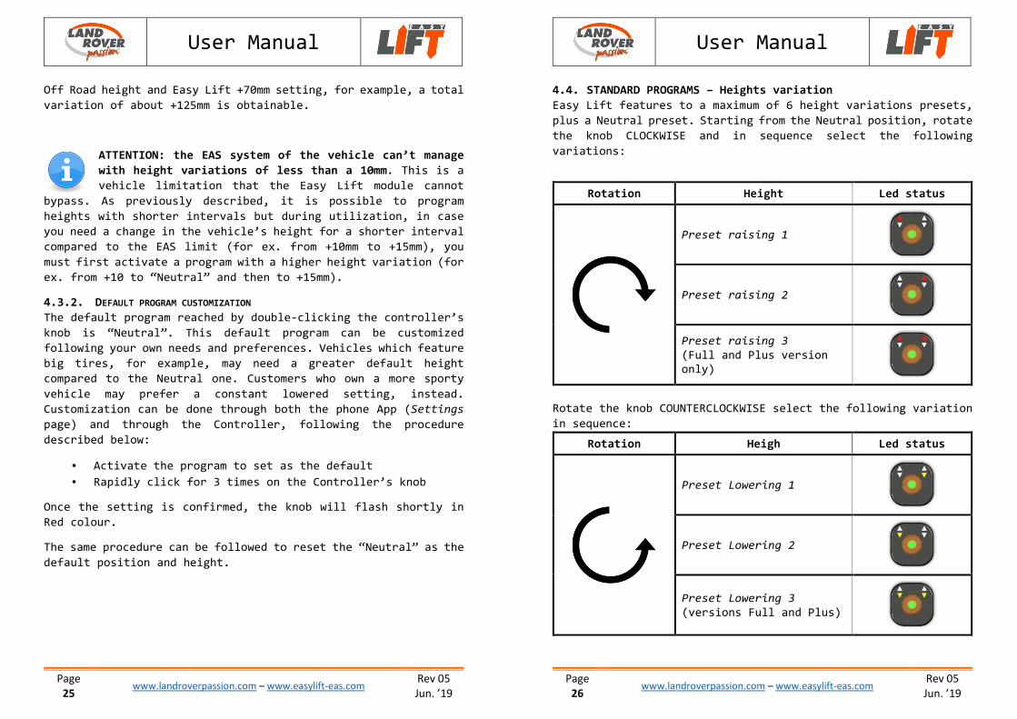
4.2. Easy Lift versions
Easy Lift is available in three versions: Full, Plus and Lite,
which differ according to the number of available features:
Program Description/heights range(*) Full Plus Lite
Heights From -35mm to +75mm Yes Yes No
From -20mm to +55mm - - Yes
Special
xWheel Alignment/Service Yes Yes Yes
Self levelling Yes No No
Extra low Yes No No
Recovery Yes No No
(*)The reachable heights are indicative and could be different from vehicle to
vehicle
4.3. Module configuration Easy Lift can be customized in every moment both in heights and
in setting the default program to automatically restore through
double-clicking on the controller’s knob.
4.3.1. HEIGHTS CUSTOMIZATION
Factory setting corresponds to:
• Lite: -20mm; +35mm; +55mm;
• Plus & Full: -30mm; -20mm; -10mm; +35mm; +55mm; +70mm
Users, through the phone App, can associate different heights to
each program, with the following restrictions:
• Maximum of 3 preset for lowerings
• Maximum of 3 preset for raisings
• No less than 5mm of variation between a program and the
next ones
Easy Lift module can be used in addition to the Land Rover
heights, in order to increase the range of combinations and
variations reachable. Thanks to the combination of the Land Rover
User Manual
Page
25 www.landroverpassion.com – www.easylift-eas.com
Rev 05
Jun. ’19
Off Road height and Easy Lift +70mm setting, for example, a total
variation of about +125mm is obtainable.
ATTENTION: the EAS system of the vehicle can’t manage
with height variations of less than a 10mm. This is a
vehicle limitation that the Easy Lift module cannot
bypass. As previously described, it is possible to program
heights with shorter intervals but during utilization, in case
you need a change in the vehicle’s height for a shorter interval
compared to the EAS limit (for ex. from +10mm to +15mm), you
must first activate a program with a higher height variation (for
ex. from +10 to “Neutral” and then to +15mm).
4.3.2. DEFAULT PROGRAM CUSTOMIZATION
The default program reached by double-clicking the controller’s
knob is “Neutral”. This default program can be customized
following your own needs and preferences. Vehicles which feature
big tires, for example, may need a greater default height
compared to the Neutral one. Customers who own a more sporty
vehicle may prefer a constant lowered setting, instead.
Customization can be done through both the phone App (Settings
page) and through the Controller, following the procedure
described below:
• Activate the program to set as the default
• Rapidly click for 3 times on the Controller’s knob
Once the setting is confirmed, the knob will flash shortly in
Red colour.
The same procedure can be followed to reset the “Neutral” as the
default position and height.
User Manual
Page
26 www.landroverpassion.com – www.easylift-eas.com
Rev 05
Jun. ’19
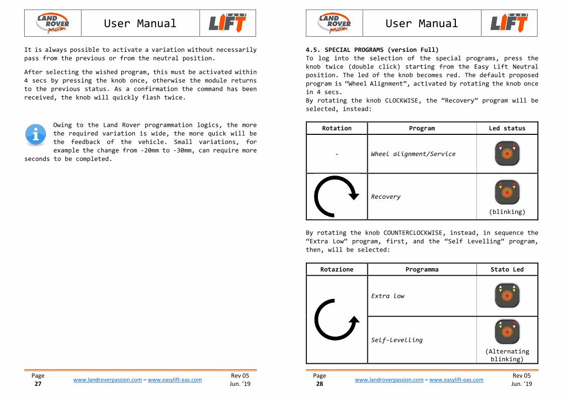
4.4. STANDARD PROGRAMS – Heights variation
Easy Lift features to a maximum of 6 height variations presets,
plus a Neutral preset. Starting from the Neutral position, rotate
the knob CLOCKWISE and in sequence select the following
variations:
Rotate the knob COUNTERCLOCKWISE select the following variation
in sequence:
Rotation Heigh Led status
Preset Lowering 1
Preset Lowering 2
Preset Lowering 3
(versions Full and Plus)
Rotation Height Led status
Preset raising 1
Preset raising 2
Preset raising 3
(Full and Plus version
only)
User Manual
Page
27 www.landroverpassion.com – www.easylift-eas.com
Rev 05
Jun. ’19
It is always possible to activate a variation without necessarily
pass from the previous or from the neutral position.
After selecting the wished program, this must be activated within
4 secs by pressing the knob once, otherwise the module returns
to the previous status. As a confirmation the command has been
received, the knob will quickly flash twice.
Owing to the Land Rover programmation logics, the more
the required variation is wide, the more quick will be
the feedback of the vehicle. Small variations, for
example the change from -20mm to -30mm, can require more
seconds to be completed.
User Manual
Page
28 www.landroverpassion.com – www.easylift-eas.com
Rev 05
Jun. ’19
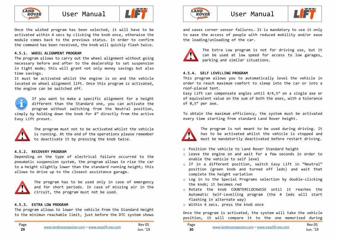
4.5. SPECIAL PROGRAMS (version Full)
To log into the selection of the special programs, press the
knob twice (double click) starting from the Easy Lift Neutral
position. The led of the knob becomes red. The default proposed
program is “Wheel Alignment”, activated by rotating the knob once
in 4 secs.
By rotating the knob CLOCKWISE, the “Recovery” program will be
selected, instead:
By rotating the knob COUNTERCLOCKWISE, instead, in sequence the
“Extra Low” program, first, and the “Self Levelling” program,
then, will be selected:
Rotazione Programma Stato Led
Extra low
Self-Levelling
(Alternating
blinking)
Rotation Program Led status
- Wheel alignment/Service
Recovery
(blinking)
User Manual
Page
29 www.landroverpassion.com – www.easylift-eas.com
Rev 05
Jun. ’19
Once the wished program has been selected, it will have to be
activated within 4 secs by clicking the knob once, otherwise the
module comes back to the previous status. In order to confirm
the command has been received, the knob will quickly flash twice.
4.5.1. WHEEL ALIGNMENT PROGRAM
The program allows to carry out the wheel alignment without going
necessary before and after to the dealership to set suspension
in tight mode; this will grant not only money savings but also
time savings.
It must be activated whilst the engine is on and the vehicle
located on wheel alignment lift. Once this program is activated,
the engine can be switched off.
If you want to make a specific alignment for a height
different than the Standard one, you can activate the
program without switching from the Neutral position,
simply by holding down the knob for 4” directly from the active
Easy Lift preset.
The program must not to be activated whilst the vehicle
is running. At the end of the operations please remember
to deactivate it by pressing the knob twice.
4.5.2. RECOVERY PROGRAM
Depending on the type of electrical failure occurred to the
pneumatic suspension system, the program allows to rise the car
to a height slightly lower than the standard running height; this
allows to drive up to the closest assistance garage.
The program has to be used only in case of emergency
and for short periods. In case of missing air in the
circuit, the program must not be used.
4.5.3. EXTRA LOW PROGRAM
The program allows to lower the vehicle from the Standard Height
to the minimun reachable limit, just before the DTC system shows
User Manual
Page
30 www.landroverpassion.com – www.easylift-eas.com
Rev 05
Jun. ’19
and saves corner sensor failures. It is mandatory to use it only
to ease the access of people with reduced mobility and/or ease
the loading/unloading of the car.
The Extra Low program is not for driving use, but it
can be used at low speed for access to low garages,
parking and similar situations.
4.5.4. SELF LEVELLING PROGRAM
This program allows you to automatically level the vehicle in
order to reach maximum comfort to sleep into the car or into a
roof-placed tent.
Easy Lift can compensate angles until 4/4,5° on a single axe or
of equivalent value on the sum of both the axes, with a tolerance
of 0,5° per axe.
To obtain the maximum efficiency, the system must be activated
every time starting from standard Land Rover height.
The program is not meant to be used during driving. It
has to be activated whilst the vehicle is stopped and
must be mandatorily deactivated before restart driving.
o Position the vehicle to Land Rover Standard height
o Leave the engine on and wait for a few seconds in order to
enable the vehicle to self level
o If in a different position, switch Easy Lift in “Neutral”
position (green knob and turned off leds) and wait that
complete the height variation
o Log in to the Special Programs selection by double-clicking
the knob; it becomes red
o Rotate the knob COUNTERCLOCKWISE until it reaches the
Automatic Self-Levelling program (the 4 leds will start
flashing in alternate way)
o Within 4 secs. press the knob once
Once the program is activated, the system will take the vehicle
position, it will compare it to the one memorized during
User Manual
Page
31 www.landroverpassion.com – www.easylift-eas.com
Rev 05
Jun. ’19
Calibration (par. 3.4.2) and will make the necessary corrections
to re-set the memorized level.
o Once levelling is completed, the vehicle can be turned off.
As previously described, owing to the Land Rover
programmation logics, the more the required variation
is wide, the more quick will be the feedback of the
vehicle. Small variations can require more seconds to
be completed. As a consequence, depending on the level difference
to compensate, the levelling operation can take a few minutes,
too. Take your time to obtain your best comfort.
In case a levelling of more than 4,5° is needed, the
system can signal an error to the suspensions (red or
yellow indicator light) or signal “Extended height”. In
such case, deactivate the program and wait for a few
seconds. The anomaly will automatically disappear. Please look
for a less offset parking and repeat the procedure.
User Manual
Page
32 www.landroverpassion.com – www.easylift-eas.com
Rev 05
Jun. ’19
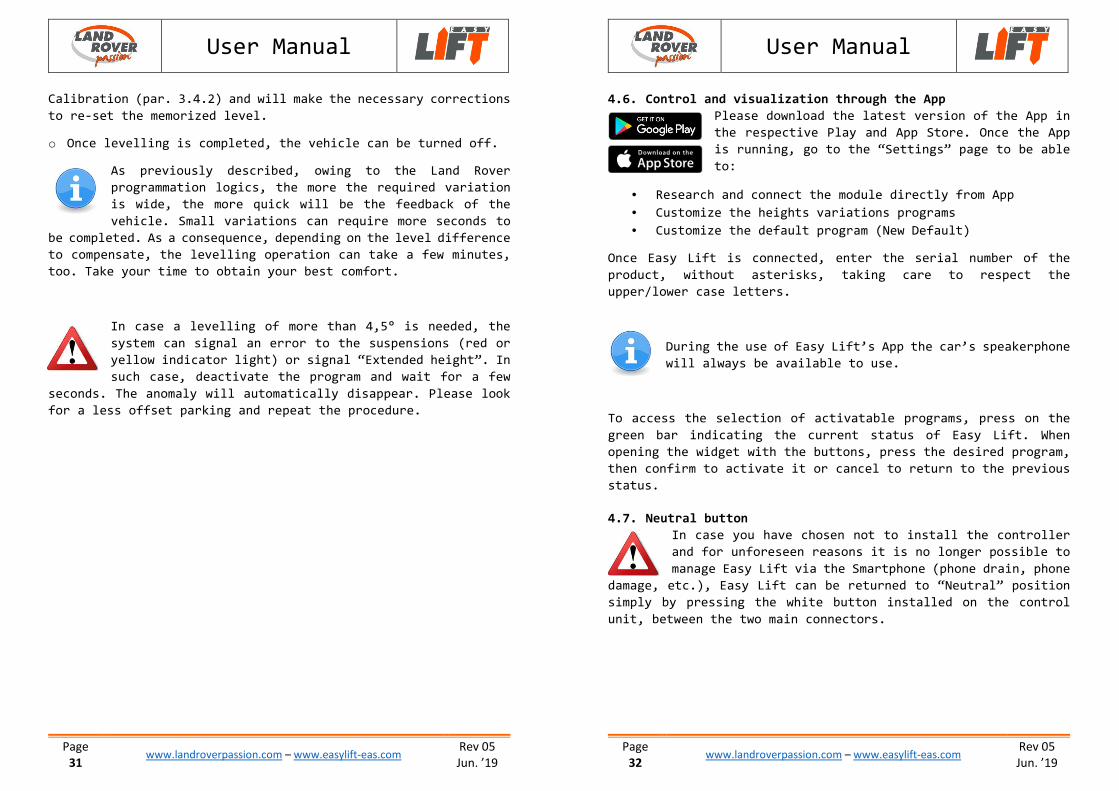
4.6. Control and visualization through the App
Please download the latest version of the App in
the respective Play and App Store. Once the App
is running, go to the “Settings” page to be able
to:
• Research and connect the module directly from App
• Customize the heights variations programs
• Customize the default program (New Default)
Once Easy Lift is connected, enter the serial number of the
product, without asterisks, taking care to respect the
upper/lower case letters.
During the use of Easy Lift’s App the car’s speakerphone
will always be available to use.
To access the selection of activatable programs, press on the
green bar indicating the current status of Easy Lift. When
opening the widget with the buttons, press the desired program,
then confirm to activate it or cancel to return to the previous
status.
4.7. Neutral button
In case you have chosen not to install the controller
and for unforeseen reasons it is no longer possible to
manage Easy Lift via the Smartphone (phone drain, phone
damage, etc.), Easy Lift can be returned to “Neutral” position
simply by pressing the white button installed on the control
unit, between the two main connectors.
User Manual
Page
33 www.landroverpassion.com – www.easylift-eas.com
Rev 05
Jun. ’19
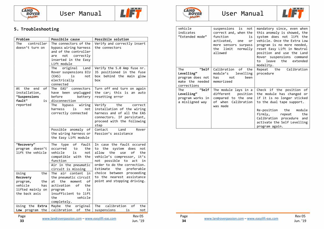
5. Troubleshooting
Problem Possibile cause Possibile solution
The controller
doesn’t turn on
The connectors of the
bypass wiring harness and of the controller
are not correctly
inserted in the Easy
Lift module
Verify and correctly insert
the connectors
The original Land
Rover suspensions ECU (EAS) is not
electrically
connected
Verify the 5.0 Amp fuse nr.
35 positioned in the fuse box behind the main glow
box
At the end of
installation,
“Suspensions
fault” is reported
The EAS’ connectors
have been unplugged
before battery
disconnection
Turn off end turn on again
the car; this is an auto
resetting error
The bypass wiring
harness is not
correctly connected
Verify the correct
installation of the wiring
harness and of all the EAS
connectors. If persistant,
proceed with the following
step
Possible anomaly of the wiring harness or
the Easy Lift module
Contact Land Rover Passion’s assistance
“Recovery”
program doesn’t
lift the vehicle
The type of fault
occurred to the
vehicle is not
compatible with the function
In case the fault occured
to the system does not
allow the use of the
vehicle’s compressor, it’s not possible to act in
order to do the correction.
Estimate the preferable
choice between proceeding
to the nearest assistance point and stopping driving.
Air in the pneumatic
circuit is missing
Using the
Recovery
program, the
vehicle has lifted mainly on
the back axis
The air content in
the pneumatic circuit
at the moment of
activation of the program is
insufficient to lift
the vehicle
completely.
Using the Extra
Low program the
Maybe the original
calibration of the
The calibration of the
suspensions is not
User Manual
Page
34 www.landroverpassion.com – www.easylift-eas.com
Rev 05
Jun. ’19
vehicle
indicates
“Extended mode”
suspensions is not
correct and, when the
function is
activated, one or
more sensors surpass the limit normally
allowed
mandatory since, even when
this anomaly is showed, the
system does not lift the
vehicle. Once the Extra Low
program is no more needed, reset Easy Lift in Neutral
position and use the Land
Rover suspensions command
to leave the extended
modality.
The “Self
Levelling” program does not
make the needed
corrections
Calibration of the
module’s levelling has not been
memorizeed
Repeat the Calibration
procedure
The “Self
Levelling”
program works in a misligned way
The module lays in a
different position
compared to the one of when Calibration
was made
Check if the position of
the module has changed or
if it is no longer sticked to the dual tape support.
Re-position the module
firmly, repeat the
Calibration procedure and
activate the Self Levelling program again.