Embed Size (px)
Citation preview

6-Information Sources and Signals
Dr. John P. AbrahamProfessor
UTRGV
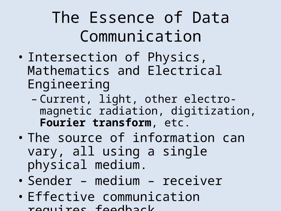
The Essence of Data Communication
• Intersection of Physics, Mathematics and Electrical Engineering– Current, light, other electro-magnetic radiation,
digitization, Fourier transform, etc.• The source of information can vary, all using a
single physical medium.• Sender – medium – receiver• Effective communication requires feedback
Information Sources
• Computer peripherals, microphones, sensors, measuring devices, etc.
• Analog or Digital Signals– Analog is continuous change– Digital is descrete change at fixed intervals
• Periodic and Aperiodic Signals– Periodic repeats itself
Sine waves and signal characteristics
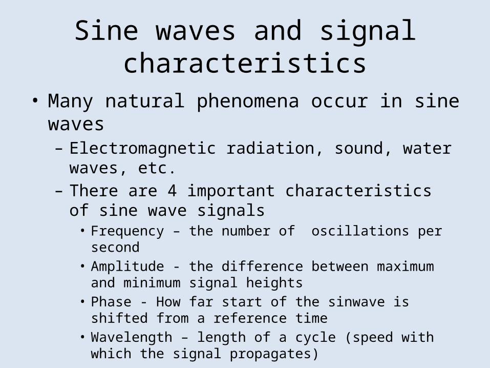
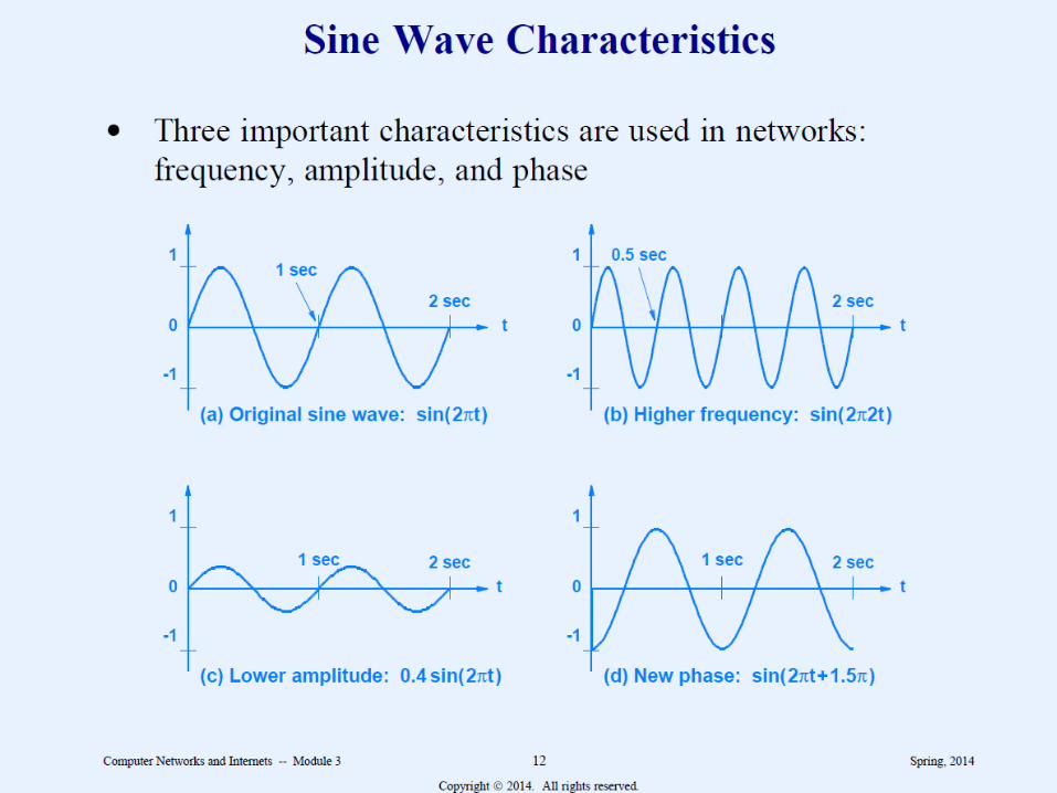
• Many natural phenomena occur in sine waves– Electromagnetic radiation, sound, water waves, etc.– There are 4 important characteristics of sine wave signals
• Frequency – the number of oscillations per second• Amplitude - the difference between maximum and minimum
signal heights• Phase - How far start of the sinwave is shifted from a reference
time• Wavelength – length of a cycle (speed with which the signal
propagates)
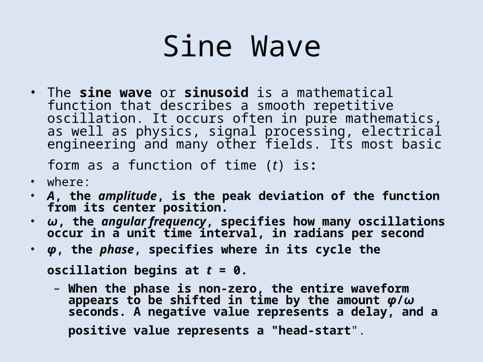
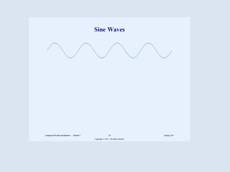
Sine Wave• The sine wave or sinusoid is a mathematical function that describes a
smooth repetitive oscillation. It occurs often in pure mathematics, as well as physics, signal processing, electrical engineering and many other fields.
Its most basic form as a function of time (t) is: • where:• A, the amplitude, is the peak deviation of the function from its center position. • ω, the angular frequency, specifies how many oscillations occur in a unit time
interval, in radians per second
• φ, the phase, specifies where in its cycle the oscillation begins at t = 0. – When the phase is non-zero, the entire waveform appears to be shifted in
time by the amount φ/ω seconds. A negative value represents a delay, and a
positive value represents a "head-start".
Composite signals• Most signals are classified as composite
because the signals can be decomposed into several simple waves.• Signals generated by modulation are usually
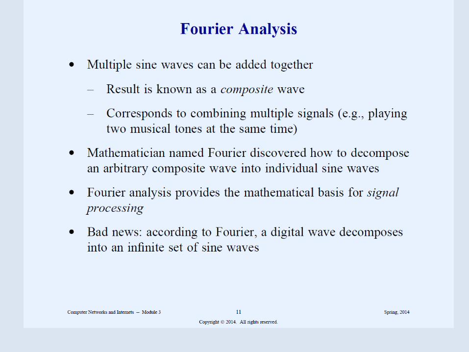
composite.• A mathematician named Fourier discovered
that it is possible to decompose a composite signal into its constituent parts. Fourier transform is used to solve many problems in science and engineering

Analog and Digital signals
• Analog is characterized by continuous mathematical function. When input changes from one value to the next it does so by moving through all possible intermediate values.
• Digital has a fixed set of valid levels, and each change consists of an instantaneous move from one level to another.
Periodic and Aperiodic Signals
• A periodic signal repeats the pattern.• Aperiodic does not repeat the pattern
THEORETICAL BASIS FOR DATA COMMUNICATION
• TRANSMIT ON WIRES BY VARYING PHYSICAL PROPERTY– VOLTAGE– CURRENT– FREQUENCY– PHASE
• TRANSMIT ON GLASS FIBER BY SENDING LIGHT PULSES
Data Rate• How much data can be sent in a given time? Depends on
number of signal levels and time it remains in each signal level before going to the next.
• If we reduce the time at each signal level, more data can be sent. But there is minimum to time required to detect the signal. Engineers measure the inverse: how many times the signal can change per second which is measured as baud. If signal remains for .001 sec, it is 1000 baud. If the system has 2 signal levels, then 1000 bits can be transmitted with 1000 baud. If it has 4 signal levels, 2000 bits can be transmitted.
Bandwidth of analog and digital signals
Difference between the highest and lowest frequencies of constituent parts as yeilded by Fourier analysis.
Ditital signals: some systems use voltage to represent digital values. Only two levels of voltage indicate 0 or 1. Multiple levels of voltage may be used to indicate multiple bits.
-5 volt = 00, -2 volt = 01, +2 volt = 10, +5 volts = 11If multiple levels are used electronics must be sensitive
enough to distinguish between voltage levels.

Bandwidth of a Digital signal
Applying Fourier analysis we find a digital signal has infinite bandwidth because a digital signal produce an infinite set of sine waves.
Analog/Digital data
Digital Data to Digital SignalsDigital Data to Analog SignalsAnalog Data to Digital SignalsAnalog Data to Analog Signals
Converting digital to analog.
Why do that? To transmit digital data over analog lines. Serial communication using modems. Basis of analog signaling is a continuous constant frequency known as the carrier signal.
Digital Data to Analog Signals
ASKFSKPSKGo to notes here to talk about modem, null
modem, dce (data communication equipment), dte (data terminal equipment). Students must know these concepts.
Digital Data to Digital SignalsDigital signal is a sequence of discrete
discontinuous voltage pulses. Each pulse is a signal element. Unipolar only positive voltage. Polar both positive and negative.NRZMultilevel Binary
Bipolar-AMIPseudoternary
BiphaseManchester and differential Manchester
Non return to zero (NRZ) and NRZi
Easiest way to encode. Use 2 diff voltage levels. During a bit transmission the voltage does not return to zero
NRZi – non return to zero, invert on ones. No transition zero. Transition one
In a twisted pair, if sending and receiving wires are improperly connected, nrzi is not affected. NRZ-I is an example of differential encoding. In decoding adjacent elements are compared for polarity changes.
Draw it on the board.
Multilevel Binary
This technique uses more than two signal levels.Bipolar AMI (alternate mark inversion)A binary 0 is represented by no line signal. Binary 1 is
represented by a positive or negative voltage. The binary ones must alternate in polarity. Draw it.
Advantage: no loss of synchronization in case of continuous one’s transmitted. Receiver can synchronize with each transmission.
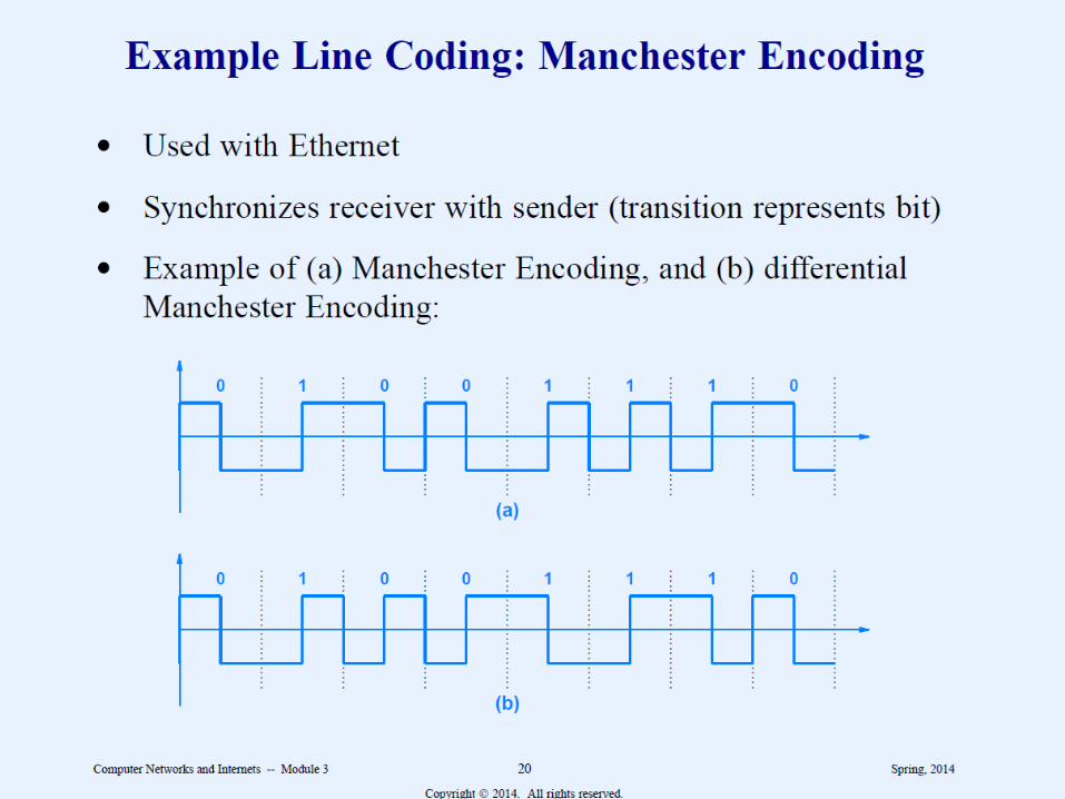
Biphase Manchester code
There is a transition at the middle of each bit period
This transition serves as a clocking mechanism. Low to hight represents 1 and high to low represents a 0.
This technique is used in ethernet local area networks, upto 10Mbps.
Manchester Encoding
Used in Ethernet Idea is to detect a transition rather than voltage
levels to define bits.
Analog Data to Digital Signals
PCM – pulse code modulation DM-delta modulation .
Encoding and Data compression
Lossy – some information is lost during compression JPEG MPEG
Lossless – all information is retained in the compressed version Repeated strings are compressed and a dictionary is created. Compressed data along with dictionary is sent to recreate the original data
Analog Data to Analog Signals
AMFMPM