Embed Size (px)
Citation preview
ROAD TUNNELS MANUAL
6. GEOMETRY
All rights reserved. © World Road Association (PIARC)
PIARC ROAD TUNNELS MANUAL © PIARC
6. Geometry
As mentioned extensively in the Chapter 1 "Strategic issues" of this Manual, the geometric characteristics have to be defined at the most early stage of the conception of a tunnel, and even of a road link comprising possibly one or more tunnels.
These characteristics are of very different natures, and can be grouped in the following categories:
the relation between construction method and cross-section the theoretical notions related to traffic capacity the general alignment of the road comprising the tunnel : number of carriageways and lanes, off-
carriageway provisions (lateral and possibly central), headroom, maximal slopes, minimal horizontal and vertical radiuses, transverse slopes, the detailed characteristics of the transverse profile inside the tunnel : width of lanes and off-carriageway provisions, headroom taking into account the construction method and the equipment to be installed the space needs for safety features as part of the cross-section : lay-bys, emergency stopping lanes, emergency service recesses, safety fences and barriers, safety recesses, etc.
the specific geometric characteristics of other features located out of the cross-section: emergency exits, evacuation galleries, by-passes, cross-connections, etc.
the influence of the geometrical characteristics on safety.
This chapter is mainly based on the Technical Reports 05.11.B " Cross section geometry in Unidirectional road tunnels" and 05.12.B "Cross section design for bi-directional road tunnels".
Section 6.1 recalls the relation between construction method and cross section.
Section 6.2 gives a summary of the theoretical notions related to traffic capacity.
Section 6.3 recalls the main rules concerning the general alignments of roads, including the main figures used in some countries, and insists on the need to maintain the largest geometrical characteristics of the outside road in the tunnel itself (with the important exception of the maximum slope, which has to be limited).
Section 6.4 deals specifically with the transverse profile of the carriageway of road tunnels, for uni- as well as bidirectional ones.
Section 6.5 concerns the vertical clearance of the tunnel.
Section 6.6 concerns the emergency lanes and the off-carriageway features, as well as the various safety features that have to be found along the tunnel.
Contributors
This chapter of the manual was written by Willy De Lathauwer (Belgium), associate member of C4 committee as ITA representative.
Fathi Tarada (UK), reviewed this Chapter.
http://tunnels.piarc.org/en/geometry/ 2 / 11
PIARC ROAD TUNNELS MANUAL © PIARC
6.1. Relation between construction method and cross section
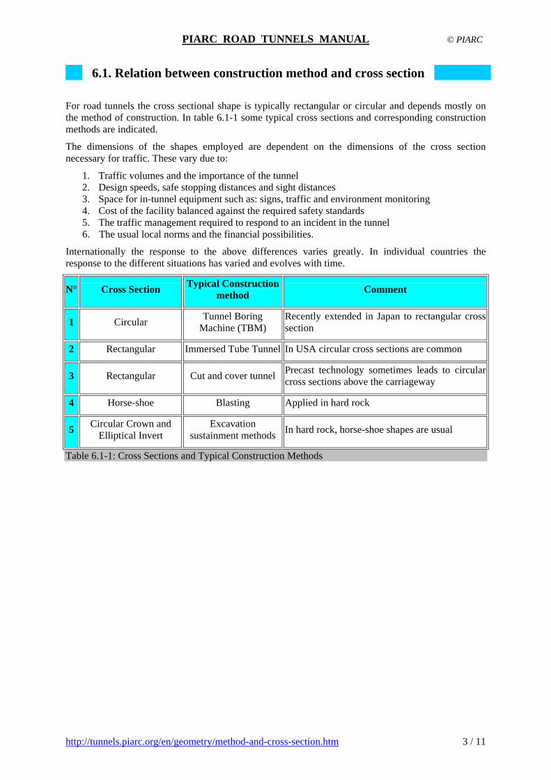
For road tunnels the cross sectional shape is typically rectangular or circular and depends mostly on the method of construction. In table 6.1-1 some typical cross sections and corresponding construction methods are indicated.
The dimensions of the shapes employed are dependent on the dimensions of the cross section necessary for traffic. These vary due to:
1. Traffic volumes and the importance of the tunnel 2. Design speeds, safe stopping distances and sight distances 3. Space for in-tunnel equipment such as: signs, traffic and environment monitoring 4. Cost of the facility balanced against the required safety standards 5. The traffic management required to respond to an incident in the tunnel 6. The usual local norms and the financial possibilities.
Internationally the response to the above differences varies greatly. In individual countries the response to the different situations has varied and evolves with time.
N° Cross Section Typical Construction
method Comment
1 Circular Tunnel Boring
Machine (TBM) Recently extended in Japan to rectangular cross section
2 Rectangular Immersed Tube Tunnel In USA circular cross sections are common
3 Rectangular Cut and cover tunnel Precast technology sometimes leads to circular cross sections above the carriageway
4 Horse-shoe Blasting Applied in hard rock
5 Circular Crown and
Elliptical Invert Excavation
sustainment methods In hard rock, horse-shoe shapes are usual
Table 6.1-1: Cross Sections and Typical Construction Methods
http://tunnels.piarc.org/en/geometry/method-and-cross-section.htm 3 / 11

PIARC ROAD TUNNELS MANUAL © PIARC
6.2. Theoretical and practical tunnel traffic capacity
The theoretical capacity of a road section is defined as the maximum through-flow of vehicles per hour. It is determined by measuring the maximum number of passenger cars in a fifteen-minute period and multiplying this by a peak hour factor. This is not an absolute maximum, but rather refers to reasonable repeatability. Expressed in this way, the capacity only depends on the number and width of lanes and off-carriageways, and the slope of the section. It does not depend on the percentage of heavy vehicles, since it is clear that this intensity will be a maximum when traffic is formed exclusively by light vehicles and regular drivers. If there is no element that limits it, this theoretical capacity is approximately 2,200 vehicles per hour per lane (v/h/l). More information is available in Chapter 4 "Capacity and speed in relation to the geometry of roads and roads tunnels" of Report 05.11.B and in Chapter 3 "Traffic speed and densities" of Report 05.12.B.
The practical capacity of a section is calculated based on the theoretical capacity without the previously mentioned restrictions (2,200 v/h/l). Limiting factors are applied based on the actual characteristics of the roadway. These main factors are:
Fw : Lane width factor, which reduces the capacity depending on the width of the lanes and the off-carriageways. It is considered that a lane does not limit the practical capacity if the width is equal to or greater than 3.60 m.
Fhv : Heavy vehicle factor, which adjusts the theoretical capacity depending on the percentage of heavy vehicles and the inclination and length of the ramp or slope of the roadway.
Fc : Correction factor due to the predominant type of driver. This factor adjusts the capacity based on whether the drivers are regular drivers along the route and if the type of traffic is that of a working day.
The practical capacity of a carriageway in one direction, Cp , is calculated then by:
Cp= 2200 . N . Fw . Fhv . Fc in which N is the number of lanes.
The factors can further be calculated and adapted according to formulas and tables given in Chapter 4 "Capacity and speed in relation to the geometry of roads and roads tunnels" of Report 05.11.B and in Chapter 3 "Traffic speed and densities" of Report 05.12.B.
More information can also be found in the HCM (Highway Capacity Manual) issued by the Transportation Research Board (USA).
http://tunnels.piarc.org/en/geometry/traffic-capacity.htm 4 / 11

PIARC ROAD TUNNELS MANUAL © PIARC
6.3. General alignment of roads and national examples
6.3.1 Horizontal alignment
Small curves should be avoided, especially if they are connected to a straight alignment. A minimal curvature of 550-600 m should be observed. The lateral clearances must also allow for longitudinal visibility in curves.
In urban tunnels, it should be adequate to consider design speeds close to the actual speed in fluid and uncongested traffic flow.
6.3.2 Longitudinal profile
Due to the influence on speed, longitudinal downgrade profiles cause more accidents, especially with high traffic volumes (increase of speed downwards).
6.3.3 Cross section
Reduced cross-sections are dangerous and may cause accidents.
Attention should be given to the point that, if the width of the carriageway and/or off-carriageway area in the tunnel and in the approach to the tunnel is less than on the open road, these changes should be implemented well before the tunnel portal and as smoothly as possible: see Chapter 4.7 "Design of tunnel portals" of Report 2008R17.
6.3.4 Height clearance
Accidents involving oversized vehicles are often recorded in rectangular tunnels or tunnels with a ceiling for ventilation purposes.
It is advised to install outside the tunnel, ahead of each portal, a signed escape route as well as a system to stop physically oversized vehicles.
More information is available in Section IV.2.6 "Height clearance" of Report 05.04.B.
6.3.5 Uni- or bidirectional tunnels
Bidirectional tunnels cause more accidents than unidirectional ones. Nevertheless users observe fairly well the prohibition to overtake in tunnels with average longitudinal gradients. In case of steep gradients it should be adequate, however, to plan an additional lane for slow vehicles.
It is strongly advised against changing the traffic direction to absorb daily traffic peaks.
Bidirectional tunnels may be economic for the phased construction of motorway tunnels, where economic considerations require bidirectional traffic operation to be planned at a first stage, then unidirectional at a second stage. However, this is under the proviso that the usable tunnel width is designed with bidirectional traffic requirements in mind and is thus wide enough, in order to absorb a number of traffic peaks (e.g. summer or winter holidays). Even if such an arrangement may be acceptable from a safety viewpoint, it must be avoided as often as possible. For urban tunnels it must be prohibited.
6.3.6 Interchanges
http://tunnels.piarc.org/en/geometry/alignment.htm 5 / 11

PIARC ROAD TUNNELS MANUAL © PIARC
http://tunnels.piarc.org/en/geometry/alignment.htm 6 / 11
Underground interchanges (slip roads in and out) may cause accidents. They must thus be correctly designed. The lighting equipment should lay emphasis on these singular points and on the geometric challenges faced by the driver. Consideration must be given to the driver’s visual perception.
Inside the tunnel, the traffic exits must be located at a distance from the portal. A number of accidents, mostly injury accidents, have occurred in tunnels where the slip road is located directly after the tunnel. In the case of tunnels with restricted space conditions, it should be adequate to plan an additional lane inside the tunnel for the exit slip road.

PIARC ROAD TUNNELS MANUAL © PIARC
6.4. Carriage way geometry
The terminology has to be defined as follows:
1. Carriageway, comprising the area inside the inner edges of the outermost traffic lane markings
2. Off-carriageway, comprising those areas in plan outside the carriageway, including edge lane markings, clearances, emergency lanes, sidewalks and safety barriers.
Fig. 6.4-1 : Example of cross section
More information is available in Chapter 2 "Terminology" of Report 05.11.B.
To aid good management, roads are classified on a hierarchical basis according to function. Road networks of highest classification are interstate connections such as the Trans European Road Network or the Interstate Highways in the USA. National networks consist of roads that connect urban regions and national economic centres. Regional networks provide connections between regional towns. Functional requirements to the distinct functional networks or roads are formulated such as speed, congestion level, distances between intersections.
Most countries have their own directives and guidelines regarding requirements to carriageway geometry. A comparison of international guidelines is given in the Chapter 5 "Traffic lanes and carriageway" of Report 05.11.B.
Country and name of guidelines or other source
Design Speed or Reference Speed
[km/h]
Width of Traffic Lane
[m]
Width of Traffic Lane Marking
[m]
Width of Carriageway [m]
Austria RVS 9.232 80 - 100 3.50 0.15 7.00
Denmark (practise) 90 - 120 3.60 0.10 7.20
France CETU 80 - 100 3.50 ? 7.00
Germany 100 (26T, 26Tr) 3.50 0.15 7.00
Germany RAS-Q 1996 70 (26t) 3.50 0.15 7.00
Germany RABT 94 110 (29.5T) 3.75 0.15 7.50
Japan 80 - 120 3.50 7.00
Japan Road Structure Ordinance
60 3.25 6.50
Fig. 6.4-2 : Comparison of international guidelines (Excerpt of table 5.1 of the Report 05.11.B)
It is recommended that the width of traffic lanes in tunnels with design velocities of 100 km/h shall not be less than 3.50 m. When it is acceptable/necessary to impose speed limits (80 or even 60 km/h) in tunnels on roads (i.e. unavoidable sharp curves, noise reduction in built up area, limited capacity necessary, cost reduction) a restriction of the width of traffic lanes (for example to 3.25 m) may help
http://tunnels.piarc.org/en/geometry/carriage-way.htm 7 / 11

PIARC ROAD TUNNELS MANUAL © PIARC
http://tunnels.piarc.org/en/geometry/carriage-way.htm 8 / 11
drivers to reduce speed and thus act as a psychological support of the speed limit. This generally has to be enforced with frequent controls and high fines. In some urban tunnels, where only light vehicles are allowed, narrower lanes are accepted; in curves attention has to be given to the influence of the bending of the pavement on the width of the structure.
More information is available in Chapter V "Traffic lanes and carriageway" of Report 05.11.B and Sections 7.1 to 7.5 of Chapter 7 "Geometric cross section" of Report 05.12.B.

PIARC ROAD TUNNELS MANUAL © PIARC
6.5. Vertical clearance
The minimum headroom above the carriageways is at least equal to the maximum (design) height of heavy good vehicles (HGV) that are allowed on the road, with additional clearance necessary to allow for movements of the vehicles due to irregularities of the pavement and the vehicle.
The minimum headroom depends on the maximum height of heavy good vehicles and varies from country to country. In most European countries the maximum height of heavy good vehicles is 4.0 m; certain countries allow higher values (UK, USA): see table 7.1 in Chapter 7 "Maintained headroom" of the Report 05.11.B.
In the European Union the maximum height of heavy good vehicles is 4.00 m, although the Geneva conventions allow a maximum of 4.3 m. If a margin of 0.20 m is added to these maximum heights in order to absorb vertical movements of the HGV, the minimum vertical clearances required are 4.20 m (4.50 m).
Above these minimum clearances, additional headroom is necessary for drivers of HGV's to feel comfortable. This comfort margin is related to the object distance. The minimum height plus the comfort margin yields the maintained headroom. If a value of 0.30m is taken for the comfort margin, the maintained headroom is 4.50 m (Geneva convention 4.80 m, UK 5.35 m, USA 4.90 m on freeways, 4.30 m on other highways).
To prevent damage of equipment mounted above the carriageway by loose tarpaulins for instance, an additional allowance is often applied.
Finally, allowance has to be made for inaccuracies in the construction, bending of the roof and possible later paving overlays see Chapter 7 "Maintained headroom" of the Report 05.11.B and Chapter 7.8 "Vertical clearances" of the Report 05.12.B.
The specific case of the geometric design of reduced height urban tunnels is treated separately, as they are normally reserved to cars and some restricted categories of (light) vans.
The full study has been made for France and implies the following specific points due to the presence mainly of cars, available in the article "Reduced height urban tunnels geometric design" (Routes/Roads 288 - 1995):
slopes : higher limits are possible : § I.3, p 40 interdistance of interchanges : § II.1, p 41 definition of the height : § II.3, pp 43-44 horizontal and lateral alignment : § III.1, pp 45-46 cross-section : § III.2, pp 46-50
http://tunnels.piarc.org/en/geometry/vertical-clearance.htm 9 / 11

PIARC ROAD TUNNELS MANUAL © PIARC
6.6. Emergency lane, off-carriageway geometry and special elements
To facilitate and clarify communication and comparison it is necessary to define a minimal set of terms regarding carriageway and off-carriageways. The working group which produced the Technical Report 05.11.B decided to apply the following terminology:
1. Carriageway, comprising the area inside the inner edges of the outermost traffic lane markings;
2. Off-carriageway, comprising those areas in plan outside the carriageway, including edge lane markings, clearances, emergency lanes, sidewalks and safety barriers : see graphs in Chapter 2 of the Report 05.11.B : Terminology
The distinction is justified in that there appears to be general agreement about the use and dimensions of the carriageway, while the dimensions of and requirements for elements of the off-carriageway differ greatly between countries. The emergency lane is defined as an "area of hard clearance to park vehicles in case of emergency".
On roads of the motorway type in the open air usually an emergency lane is provided. Hard clearances in tunnels are often restricted for economic reasons. This restriction can make it impossible for broken-down vehicles to park on the hard clearance adjacent to the driving lane without occupying part of the driving lane and thus disrupting traffic flow.
The geometry of off-carriageways varies between different countries, e.g. no general rules or figures can be given. In many countries, due to costs, the width of the hard clearance is too small to park a vehicle adequately. Therefore at certain distances lay-bys are provided. However in Norwegian and Spanish experience only 40 % of the broken down vehicles effectively reach or use the lay-bys. This demonstrates that lay-bys cannot completely replace emergency lanes: see Sections 8 to 10 of Chapter III "Breakdowns" of Report 05.04.B.
The hard clearance should give the possibility to park a stranded car outside the carriageway. Therefore the width measured from the outer side of the edge lane marking should be at least the width of a passenger car (1.75 m) plus a width of 0.50 m. to enable motorists to descend, resulting in a hard clearance of 2.45 m.
In case also heavy trucks should be parked outside the carriageway a width of (2.50 + 0.50 + 0.20 =) 3.20 m is required as explained in Chapter 6 "The off-carriageway" of the Report 05.11.B.
Safety barriers are commonly referred to as "massive construction to guide vehicles colliding with the tunnel side-wall safely back in the direction of traffic". It differs from guard rails, which are a flexible or frangible beam type construction supported on poles to prevent vehicles colliding with the tunnel side-wall.
Figure 6.6-1 : Typical alignment of safety barriers in the off-carriageway
http://tunnels.piarc.org/en/geometry/special.htm 10 / 11

PIARC ROAD TUNNELS MANUAL © PIARC
http://tunnels.piarc.org/en/geometry/special.htm 11 / 11
In the case of tunnels it is questionable whether object distance is determined by the distance between the inner side of the edge lane marking and the kerb of walkways, the front of safety barriers or guide rails, or the tunnel side-wall. There is general agreement that in case low level walkways are employed the distance to the tunnel wall is a good measure. When no walkways are present the distance to the base or to the top level of the safety barriers has to be considered.
Especially in tunnels drivers prefer a certain distance to the wall (or walkway, guide rail or safety barrier) due to smaller movements of the eye-angle when fixed on objects. Experience shows that where object distance in tunnels is smaller than on the adjoining road motorists change course to keep distance from the tunnel wall: see Chapter 6 "The off-carriageway" of the Report 05.11.B.
If vehicles crossing the edge lane marking cannot be redirected in time then the consequences of collision with the wall must be minimized. This can be achieved by means of safety barriers or guard rails. Safety barriers require less space than guard rails. When vehicles collide with safety barriers at small (acute) angles they can be guided back in the direction of traffic and there is a chance of preventing major accidents. When vehicles collide with safety barriers at large (obtuse) angles the results of the collision may be more serious. Guard rails are not as effective as safety barriers at correcting/redirecting errant vehicles; however, they cause less damage in a collision at an obtuse angle. That is why safety barriers are to be preferred in case of narrow hard clearances and guard rails in case of broad hard clearances.
As guard rails require bending space this would mean extra width of the tunnel, which in many cases is not feasible from an economic point of view. Especially at restricted speed, safety barriers perform well. Moreover, barriers need less maintenance.