Embed Size (px)
Citation preview
6. Gas Turbines 1 / 140Thermal Fluid Techniques in Plants
6. Gas Turbines
6. Gas Turbines 2 / 140Thermal Fluid Techniques in Plants
Compressor 192
Fundamentals of Gas Turbines 21
Turbine 784
Combustor 403
6. Gas Turbines 3 / 140Thermal Fluid Techniques in Plants
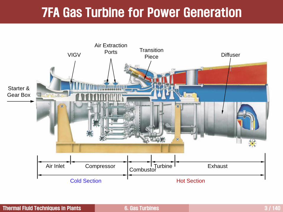
Starter &
Gear Box
Air Inlet CompressorCombustor
Turbine Exhaust
VIGV
Air Extraction
PortsDiffuser
Transition
Piece
Cold Section Hot Section
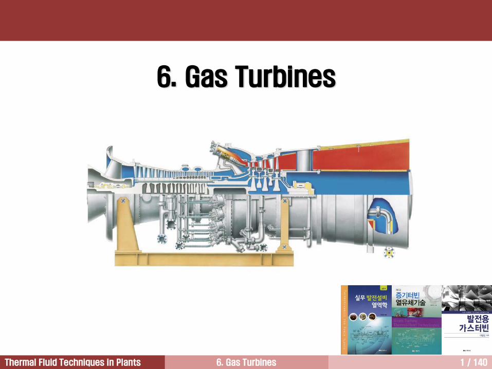
7FA Gas Turbine for Power Generation
6. Gas Turbines 4 / 140Thermal Fluid Techniques in Plants
In a gas turbine, the working fluid for transforming thermal energy into rotating mechanical energy is the hot
combustion gas, hence the term “gas turbine.”
The first power generation gas turbine was introduced by ABB in 1937. It was a standby unit with a thermal
efficiency of 17%.
The gas turbine technology has many applications. The original jet engine technology was first made into a
heavy duty application for mechanical drive purposes.
Pipeline pumping stations, gas compressor plants, and various modes of transportation have successfully
used gas turbines.
While the mechanical drive applications continue to have widespread use, the technology has advanced into
larger gas turbine designs that are coupled to electric generators for power generation applications.
Gas turbine generators are self-contained packaged power plants.
Air compression, fuel delivery, combustion, expansion of combustion gas through a turbine, and electricity
generation are all accomplished in a compact combination of equipment usually provided by a single
supplier under a single contract.
The advantages of the heavy-duty gas turbines are their long life, high availability, and slightly higher overall
efficiencies. The noise level from the heavy-duty gas turbines is considerably less than gas turbines for
aviation.
Gas Turbine
6. Gas Turbines 5 / 140Thermal Fluid Techniques in Plants
Idealized Brayton Cycle [1/3]
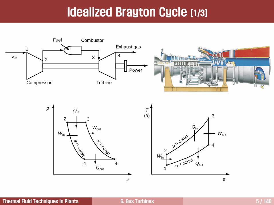
Compressor
Fuel Combustor
Turbine
Air
Power
Exhaust gas1
243
p
2
1
T
(h)
s
Qin
3
41
2
3
4
Qout
Win
Wout
Win
Wout
Qin
Qout
6. Gas Turbines 6 / 140Thermal Fluid Techniques in Plants
The entering air is compressed to higher pressure.
No heat is added. However, compression raises the air temperature so that the discharged air has
higher temperature and pressure.
The mechanical energy transmitted from the turbine is used to compress the air.
Compression Process (1 2)
Compressed air enters the combustor, where fuel is injected and combustion occurs.
Combustion occurs at constant pressure. However, pressure decreases slightly in the practical process.
Although high local temperatures are reached within the primary combustion zone (approaching
stoichiometric conditions), the combustion system is designed to provide mixing, burning, dilution,
cooling.
Combustion mixture leaves with mixed average temperature.
The chemical energy contained in the fuel is converted into thermal energy.
Combustion Process (2 3)
Idealized Brayton Cycle [2/3]
6. Gas Turbines 7 / 140Thermal Fluid Techniques in Plants
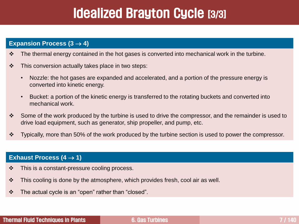
The thermal energy contained in the hot gases is converted into mechanical work in the turbine.
This conversion actually takes place in two steps:
• Nozzle: the hot gases are expanded and accelerated, and a portion of the pressure energy is
converted into kinetic energy.
• Bucket: a portion of the kinetic energy is transferred to the rotating buckets and converted into
mechanical work.
Some of the work produced by the turbine is used to drive the compressor, and the remainder is used to
drive load equipment, such as generator, ship propeller, and pump, etc.
Typically, more than 50% of the work produced by the turbine section is used to power the compressor.
Expansion Process (3 4)
Exhaust Process (4 1)
This is a constant-pressure cooling process.
This cooling is done by the atmosphere, which provides fresh, cool air as well.
The actual cycle is an “open” rather than “closed”.
Idealized Brayton Cycle [3/3]
6. Gas Turbines 8 / 140Thermal Fluid Techniques in Plants
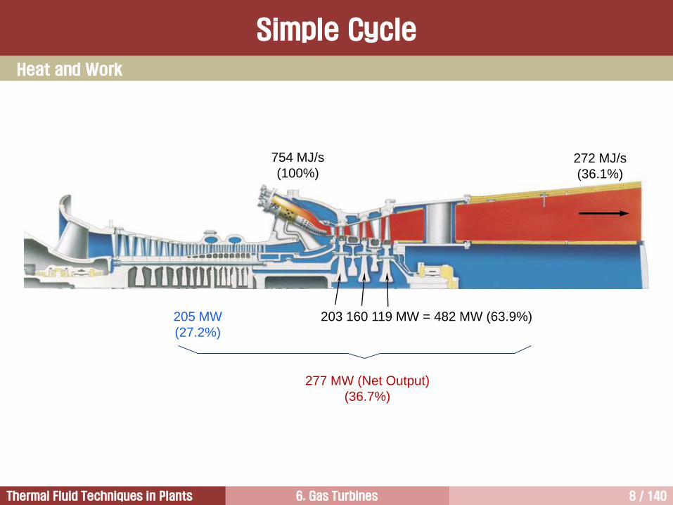
Heat and Work
754 MJ/s
(100%)
205 MW
(27.2%)
203 160 119 MW = 482 MW (63.9%)
277 MW (Net Output)
(36.7%)
272 MJ/s
(36.1%)
Simple Cycle
6. Gas Turbines 9 / 140Thermal Fluid Techniques in Plants
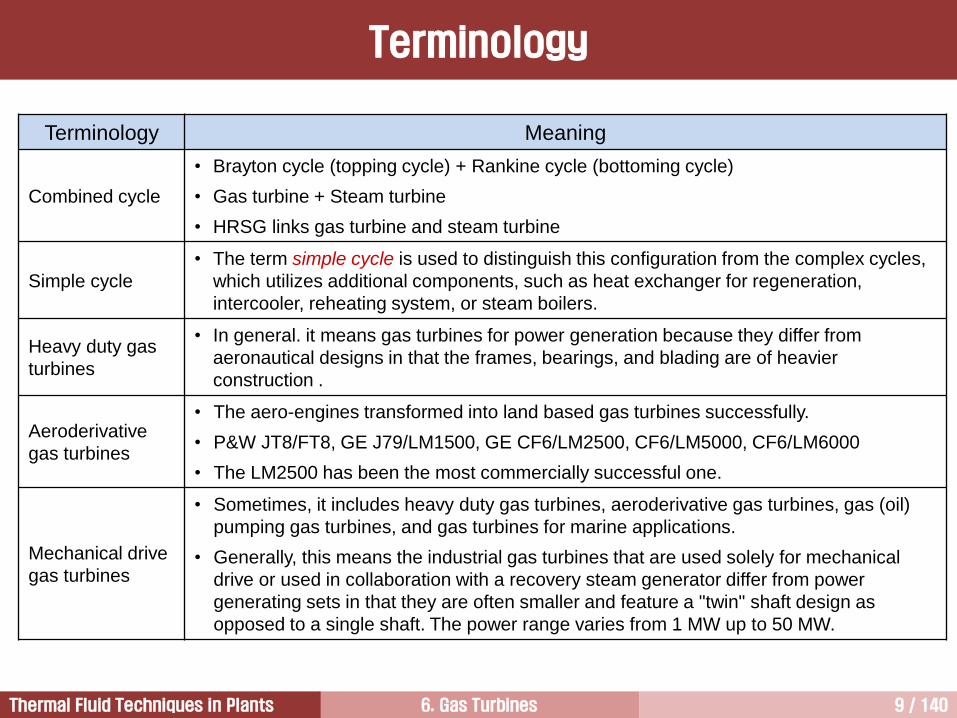
Terminology
Terminology Meaning
Combined cycle
• Brayton cycle (topping cycle) + Rankine cycle (bottoming cycle)
• Gas turbine + Steam turbine
• HRSG links gas turbine and steam turbine
Simple cycle
• The term simple cycle is used to distinguish this configuration from the complex cycles,
which utilizes additional components, such as heat exchanger for regeneration,
intercooler, reheating system, or steam boilers.
Heavy duty gas
turbines
• In general. it means gas turbines for power generation because they differ from
aeronautical designs in that the frames, bearings, and blading are of heavier
construction .
Aeroderivative
gas turbines
• The aero-engines transformed into land based gas turbines successfully.
• P&W JT8/FT8, GE J79/LM1500, GE CF6/LM2500, CF6/LM5000, CF6/LM6000
• The LM2500 has been the most commercially successful one.
Mechanical drive
gas turbines
• Sometimes, it includes heavy duty gas turbines, aeroderivative gas turbines, gas (oil)
pumping gas turbines, and gas turbines for marine applications.
• Generally, this means the industrial gas turbines that are used solely for mechanical
drive or used in collaboration with a recovery steam generator differ from power
generating sets in that they are often smaller and feature a "twin" shaft design as
opposed to a single shaft. The power range varies from 1 MW up to 50 MW.
6. Gas Turbines 10 / 140Thermal Fluid Techniques in Plants
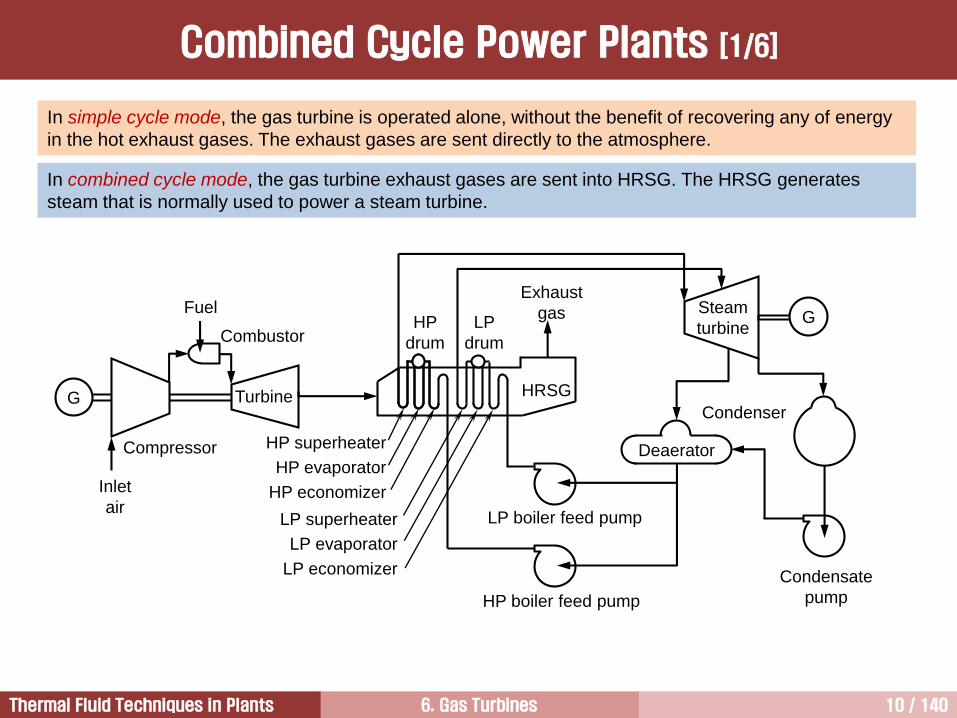
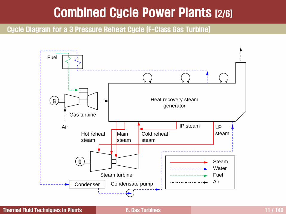
In simple cycle mode, the gas turbine is operated alone, without the benefit of recovering any of energy
in the hot exhaust gases. The exhaust gases are sent directly to the atmosphere.
In combined cycle mode, the gas turbine exhaust gases are sent into HRSG. The HRSG generates
steam that is normally used to power a steam turbine.
Combined Cycle Power Plants [1/6]
Compressor
Fuel
Combustor
Turbine
Inlet
air
Steam
turbine
G
G
Condenser
Deaerator
Condensate
pumpHP boiler feed pump
LP boiler feed pump
HP superheater
HP evaporator
HP economizer
LP superheater
LP evaporator
LP economizer
HP
drum
LP
drum
Exhaust
gas
HRSG
6. Gas Turbines 11 / 140Thermal Fluid Techniques in Plants
Cycle Diagram for a 3 Pressure Reheat Cycle (F-Class Gas Turbine)
Combined Cycle Power Plants [2/6]
Condenser
G
G
Fuel
Air
Gas turbine
Heat recovery steam
generator
IP steam LP
steamCold reheat
steam
Hot reheat
steam
Main
steam
Steam turbine
Condensate pump
Steam
Water
Fuel
Air
6. Gas Turbines 12 / 140Thermal Fluid Techniques in Plants
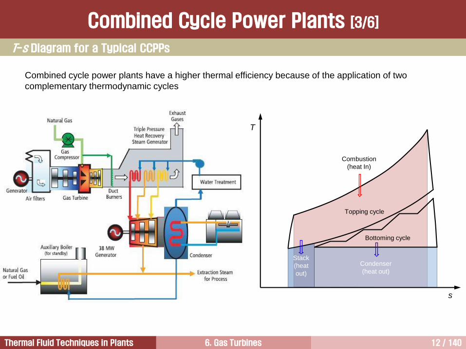
Combined cycle power plants have a higher thermal efficiency because of the application of two
complementary thermodynamic cycles
T-s Diagram for a Typical CCPPs
Combined Cycle Power Plants [3/6]
Condenser
(heat out)
T
s
Topping cycle
Bottoming cycle
Combustion
(heat In)
Stack
(heat
out)
6. Gas Turbines 13 / 140Thermal Fluid Techniques in Plants
Combined cycle power plant means a gas turbine operated with the Brayton cycle, is combined with a heat
recover steam generator and steam turbine operated with the Rankine cycle, in one plant.
When two cycles are combined, the efficiency increases higher than that of one cycle alone.
Thermal cycles with the same or with different working fluid can be combined.
In general, a combination of cycles with different working fluid has good characteristics because their
advantages can complement one another.
Normally, when two cycles are combined, the cycle operating at the higher temperature level is called as
topping cycle. The waste heat is used for second process that is operated at the lower temperature level,
and is called as bottoming cycle.
The combination used today for commercial power generation is that of a gas topping cycle with a
water/steam bottoming cycle. In this case heat can be introduced at higher temperature and exhausted at
very low temperature.
Temperature of the air used as a working fluid of gas turbines can be increased very high under lower
pressure. Water/steam used as a working fluid can contain very high level of energy at lower temperature
because it has very high specific heat.
Normally the topping and bottoming cycles are coupled in a heat exchanger.
Generals [1/2]
Combined Cycle Power Plants [4/6]
6. Gas Turbines 14 / 140Thermal Fluid Techniques in Plants
Air is used as a working fluid in gas turbines having high turbine inlet temperatures because it is easy to get
and has good properties for topping cycle.
Steam/water is an ideal material for bottoming cycle because it is inexpensive, easy to get, non-hazardous,
and suitable for medium and low temperature ranges.
The initial breakthrough of gas-steam cycle onto the commercial power plant market was possible due to
the development of the gas turbine.
In the late 1970s, EGT reached sufficiently high level that can be used for high efficiency combined cycles.
The breakthrough was made easier because gas turbines have been used for power generation as a simple
cycle and steam turbines have been used widely.
For this reason, the combined cycle, which has high efficiency, low installation cost, fast delivery time, had
been developed easily.
Generals [2/2]
Combined Cycle Power Plants [5/6]
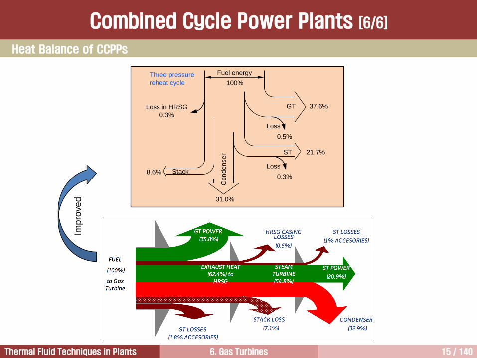
6. Gas Turbines 15 / 140Thermal Fluid Techniques in Plants
Fuel energy
100%
GT 37.6%
ST 21.7%
Condenser
31.0%
Stack8.6%
Loss in HRSG
0.3%
Loss
0.5%
Loss
0.3%
Three pressure
reheat cycleIm
pro
ve
d
Heat Balance of CCPPs
Combined Cycle Power Plants [6/6]
6. Gas Turbines 16 / 140Thermal Fluid Techniques in Plants
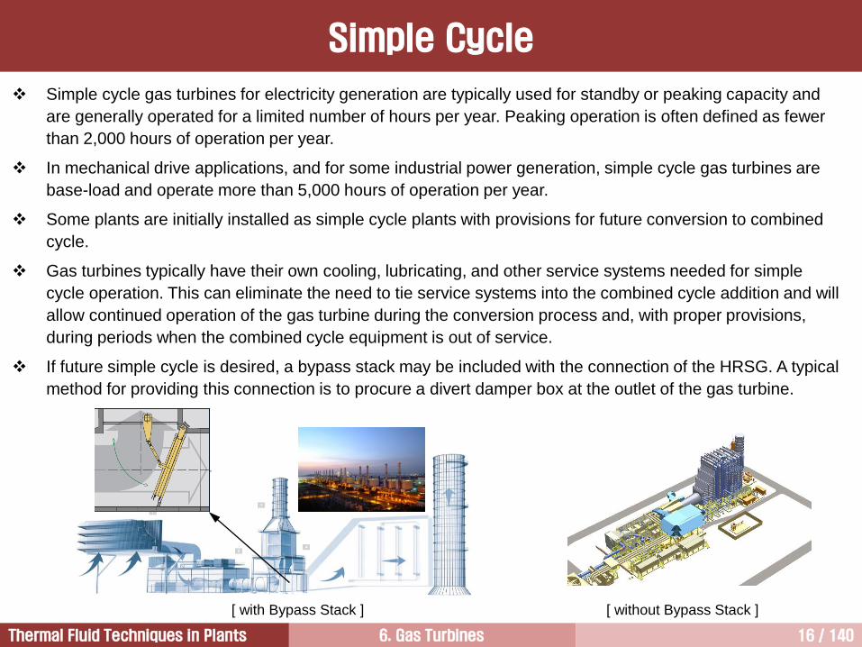
Simple cycle gas turbines for electricity generation are typically used for standby or peaking capacity and
are generally operated for a limited number of hours per year. Peaking operation is often defined as fewer
than 2,000 hours of operation per year.
In mechanical drive applications, and for some industrial power generation, simple cycle gas turbines are
base-load and operate more than 5,000 hours of operation per year.
Some plants are initially installed as simple cycle plants with provisions for future conversion to combined
cycle.
Gas turbines typically have their own cooling, lubricating, and other service systems needed for simple
cycle operation. This can eliminate the need to tie service systems into the combined cycle addition and will
allow continued operation of the gas turbine during the conversion process and, with proper provisions,
during periods when the combined cycle equipment is out of service.
If future simple cycle is desired, a bypass stack may be included with the connection of the HRSG. A typical
method for providing this connection is to procure a divert damper box at the outlet of the gas turbine.
Simple Cycle
[ with Bypass Stack ] [ without Bypass Stack ]
6. Gas Turbines 17 / 140Thermal Fluid Techniques in Plants
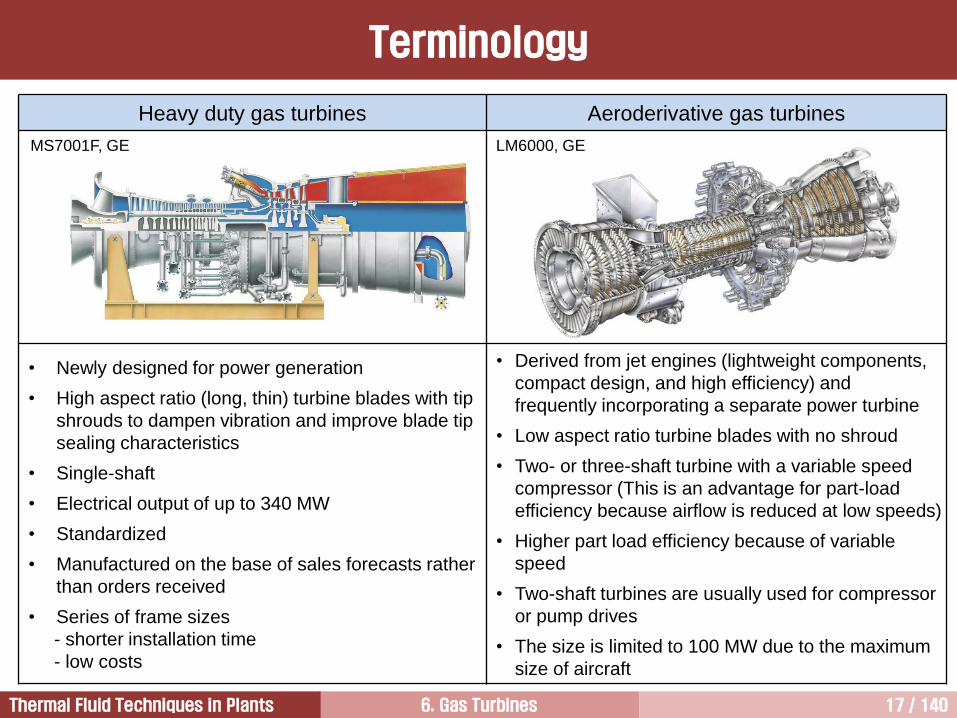
Heavy duty gas turbines Aeroderivative gas turbines
• Newly designed for power generation
• High aspect ratio (long, thin) turbine blades with tip
shrouds to dampen vibration and improve blade tip
sealing characteristics
• Single-shaft
• Electrical output of up to 340 MW
• Standardized
• Manufactured on the base of sales forecasts rather
than orders received
• Series of frame sizes
- shorter installation time
- low costs
• Derived from jet engines (lightweight components,
compact design, and high efficiency) and
frequently incorporating a separate power turbine
• Low aspect ratio turbine blades with no shroud
• Two- or three-shaft turbine with a variable speed
compressor (This is an advantage for part-load
efficiency because airflow is reduced at low speeds)
• Higher part load efficiency because of variable
speed
• Two-shaft turbines are usually used for compressor
or pump drives
• The size is limited to 100 MW due to the maximum
size of aircraft
MS7001F, GE LM6000, GE
Terminology
6. Gas Turbines 18 / 140Thermal Fluid Techniques in Plants
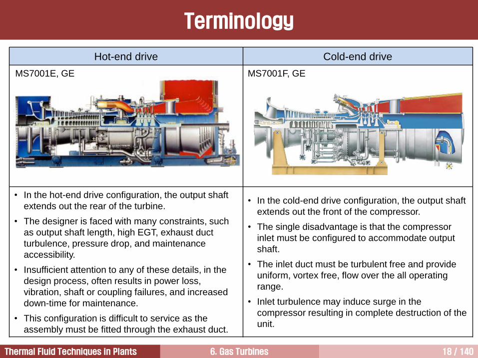
Hot-end drive Cold-end drive
• In the hot-end drive configuration, the output shaft
extends out the rear of the turbine.
• The designer is faced with many constraints, such
as output shaft length, high EGT, exhaust duct
turbulence, pressure drop, and maintenance
accessibility.
• Insufficient attention to any of these details, in the
design process, often results in power loss,
vibration, shaft or coupling failures, and increased
down-time for maintenance.
• This configuration is difficult to service as the
assembly must be fitted through the exhaust duct.
• In the cold-end drive configuration, the output shaft
extends out the front of the compressor.
• The single disadvantage is that the compressor
inlet must be configured to accommodate output
shaft.
• The inlet duct must be turbulent free and provide
uniform, vortex free, flow over the all operating
range.
• Inlet turbulence may induce surge in the
compressor resulting in complete destruction of the
unit.
MS7001E, GE MS7001F, GE
Terminology
6. Gas Turbines 19 / 140Thermal Fluid Techniques in Plants
Compressor2
Fundamentals of Gas Turbines1
Turbine4
Combustor3

6. Gas Turbines 20 / 140Thermal Fluid Techniques in Plants
7EA, GE
Configuration of a Compressor
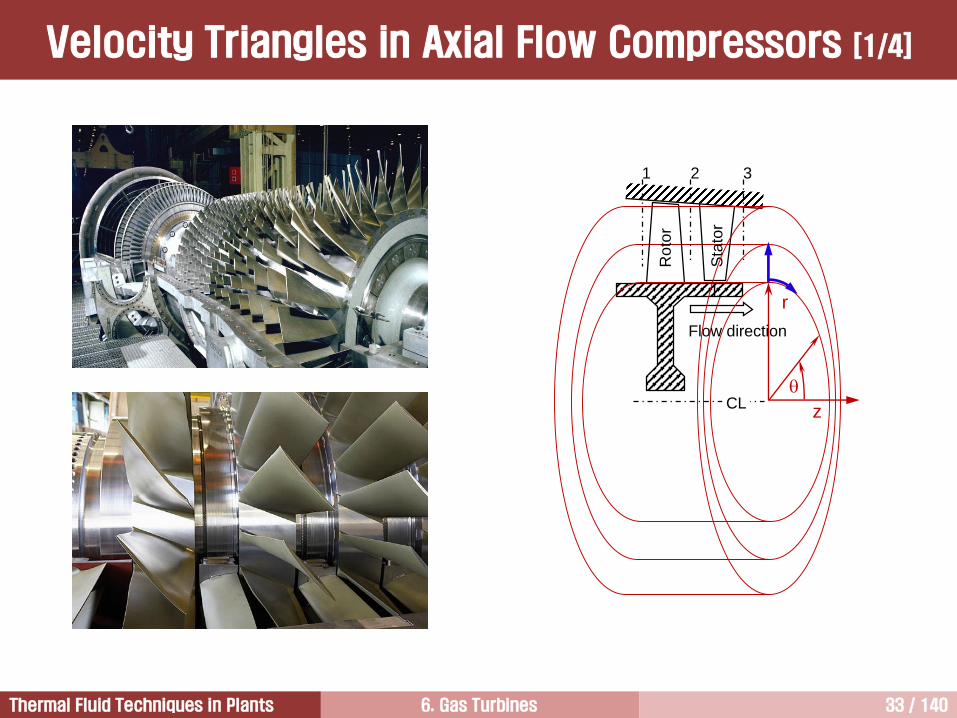
6. Gas Turbines 21 / 140Thermal Fluid Techniques in Plants
Structure
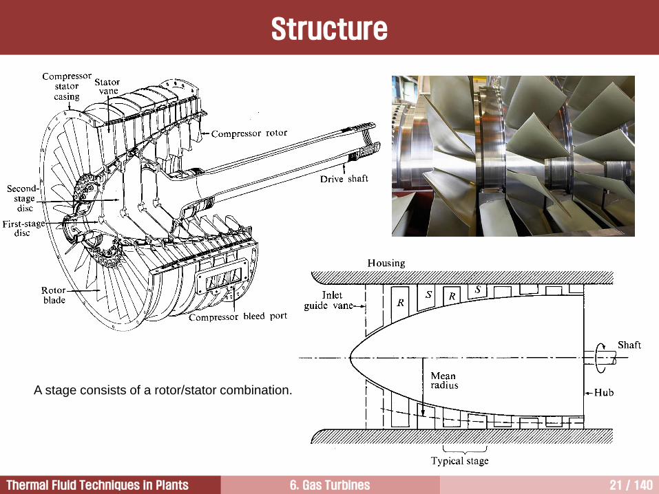
A stage consists of a rotor/stator combination.
6. Gas Turbines 22 / 140Thermal Fluid Techniques in Plants
Introduction to Compressor
If pressure rise is small and mass flow is large, the device is a called a fan, whereas if the pressure rise is
high, the device is called a compressor. Sometimes a middle-range pressure rise device is termed a blower.
The compressors in most gas turbine applications, especially units over 5 MW, use axial flow compressors.
The axial compressor is the most complicated component to design in an aerodynamic point of view.
An axial flow compressor is one which the flow enters the compressor in an axial direction (parallel with the
axis of rotation), and exits from the gas turbine also in an axial direction.
The axial flow compressor consumes around 50% of the power produced by the turbine section of the gas
turbine.
The increase in gas turbine efficiency is dependent on four basic parameters: pressure ratio, TIT,
compressor efficiency, and turbine efficiency.
In an axial flow compressor, air passes from one stage to the next, each stage raising the pressure slightly.
However, by producing low-pressure increases on the order of 1.05:1 to 1.3:1, very high compressor
efficiency can be obtained. The use of multiple stages permits overall pressure increases up to 40:1.
The industrial gas turbine has been conservative in the pressure ratio and TIT. This is because the industrial
gas turbines given up high performance for both rugged operation and long life.
However, this has all changed in the last 10 years. The performance of the industrial gas turbines improved
dramatically to overcome the increased energy cost. In addition, the performance gap between aerospace
engines and industrial ones reduced dramatically.
6. Gas Turbines 23 / 140Thermal Fluid Techniques in Plants
Growth of Pressure Ratio
Compressor
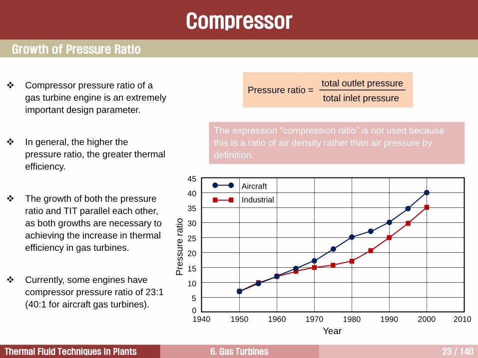
Pressure ratio =total inlet pressure
total outlet pressure
The expression “compression ratio” is not used because
this is a ratio of air density rather than air pressure by
definition.
Compressor pressure ratio of a
gas turbine engine is an extremely
important design parameter.
In general, the higher the
pressure ratio, the greater thermal
efficiency.
The growth of both the pressure
ratio and TIT parallel each other,
as both growths are necessary to
achieving the increase in thermal
efficiency in gas turbines.
Currently, some engines have
compressor pressure ratio of 23:1
(40:1 for aircraft gas turbines).
Year
Pre
ssu
re r
atio
1940 1950 1960 1970 1980 1990 2000 2010
45
40Aircraft
Industrial35
30
25
20
15
10
5
0
6. Gas Turbines 24 / 140Thermal Fluid Techniques in Plants
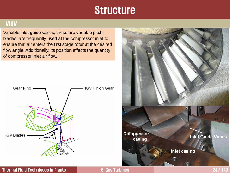
Variable inlet guide vanes, those are variable pitch
blades, are frequently used at the compressor inlet to
ensure that air enters the first stage rotor at the desired
flow angle. Additionally, its position affects the quantity
of compressor inlet air flow.
Structure
VIGV
6. Gas Turbines 25 / 140Thermal Fluid Techniques in Plants
VIGV
Structure
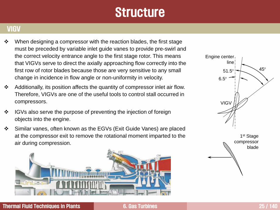
When designing a compressor with the reaction blades, the first stage
must be preceded by variable inlet guide vanes to provide pre-swirl and
the correct velocity entrance angle to the first stage rotor. This means
that VIGVs serve to direct the axially approaching flow correctly into the
first row of rotor blades because those are very sensitive to any small
change in incidence in flow angle or non-uniformity in velocity.
Additionally, its position affects the quantity of compressor inlet air flow.
Therefore, VIGVs are one of the useful tools to control stall occurred in
compressors.
IGVs also serve the purpose of preventing the injection of foreign
objects into the engine.
Similar vanes, often known as the EGVs (Exit Guide Vanes) are placed
at the compressor exit to remove the rotational moment imparted to the
air during compression.
6.5
51.5 45
Engine center
line
VIGV
1st Stage
compressor
blade
6. Gas Turbines 26 / 140Thermal Fluid Techniques in Plants
Rotor and Stator [1/3]
6. Gas Turbines 27 / 140Thermal Fluid Techniques in Plants
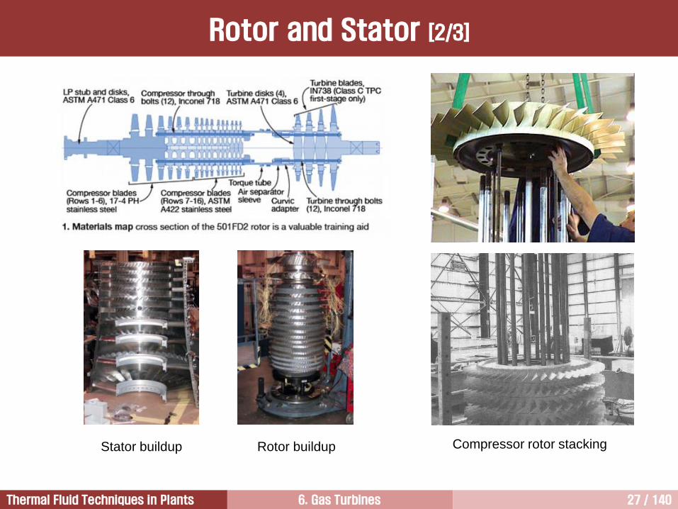
Compressor rotor stackingStator buildup Rotor buildup
Rotor and Stator [2/3]
6. Gas Turbines 28 / 140Thermal Fluid Techniques in Plants
Rotor and Stator [3/3]
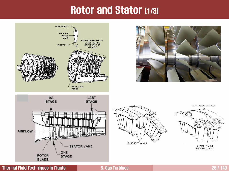
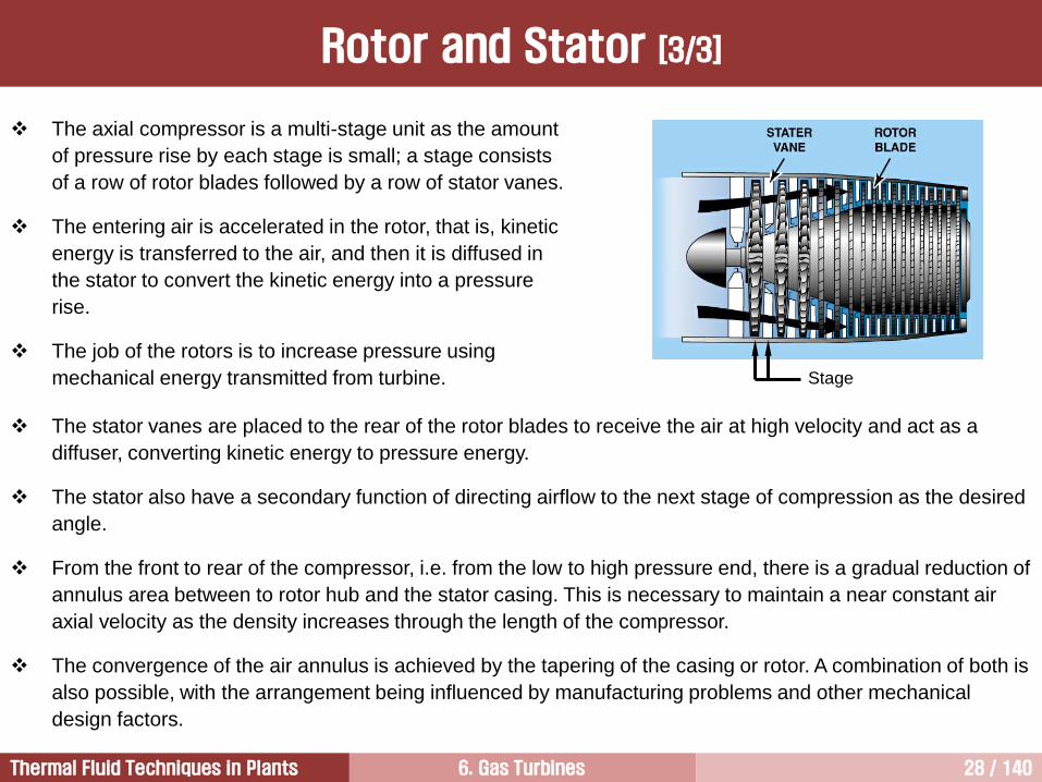
The axial compressor is a multi-stage unit as the amount
of pressure rise by each stage is small; a stage consists
of a row of rotor blades followed by a row of stator vanes.
The entering air is accelerated in the rotor, that is, kinetic
energy is transferred to the air, and then it is diffused in
the stator to convert the kinetic energy into a pressure
rise.
The job of the rotors is to increase pressure using
mechanical energy transmitted from turbine. Stage
The stator vanes are placed to the rear of the rotor blades to receive the air at high velocity and act as a
diffuser, converting kinetic energy to pressure energy.
The stator also have a secondary function of directing airflow to the next stage of compression as the desired
angle.
From the front to rear of the compressor, i.e. from the low to high pressure end, there is a gradual reduction of
annulus area between to rotor hub and the stator casing. This is necessary to maintain a near constant air
axial velocity as the density increases through the length of the compressor.
The convergence of the air annulus is achieved by the tapering of the casing or rotor. A combination of both is
also possible, with the arrangement being influenced by manufacturing problems and other mechanical
design factors.
6. Gas Turbines 29 / 140Thermal Fluid Techniques in Plants
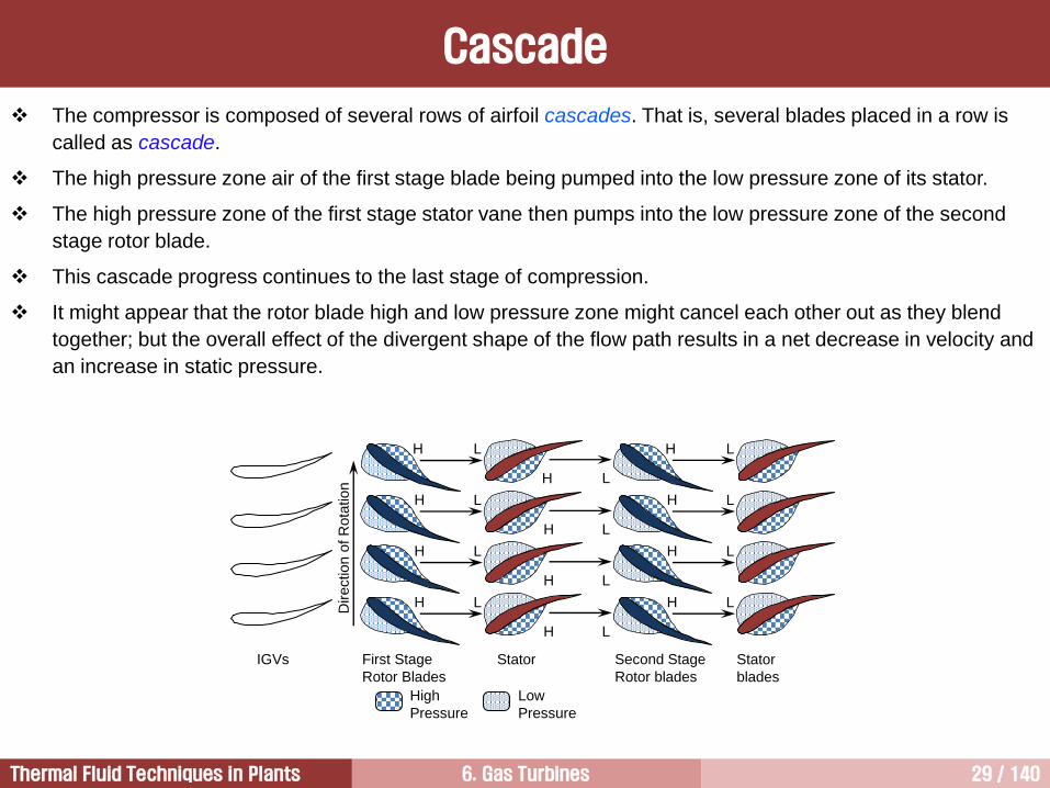
The compressor is composed of several rows of airfoil cascades. That is, several blades placed in a row is
called as cascade.
The high pressure zone air of the first stage blade being pumped into the low pressure zone of its stator.
The high pressure zone of the first stage stator vane then pumps into the low pressure zone of the second
stage rotor blade.
This cascade progress continues to the last stage of compression.
It might appear that the rotor blade high and low pressure zone might cancel each other out as they blend
together; but the overall effect of the divergent shape of the flow path results in a net decrease in velocity and
an increase in static pressure.
Cascade
First Stage
Rotor Blades
Stator
High
Pressure
Low
Pressure
IGVs
Direction o
f R
ota
tion
H
H
H
H
L
L
L
L
Second Stage
Rotor blades
Stator
blades
H
H
H
H
L
L
L
L
H
H
H
H
L
L
L
L
6. Gas Turbines 30 / 140Thermal Fluid Techniques in Plants
Compressor Blade Nomenclature [1/3]
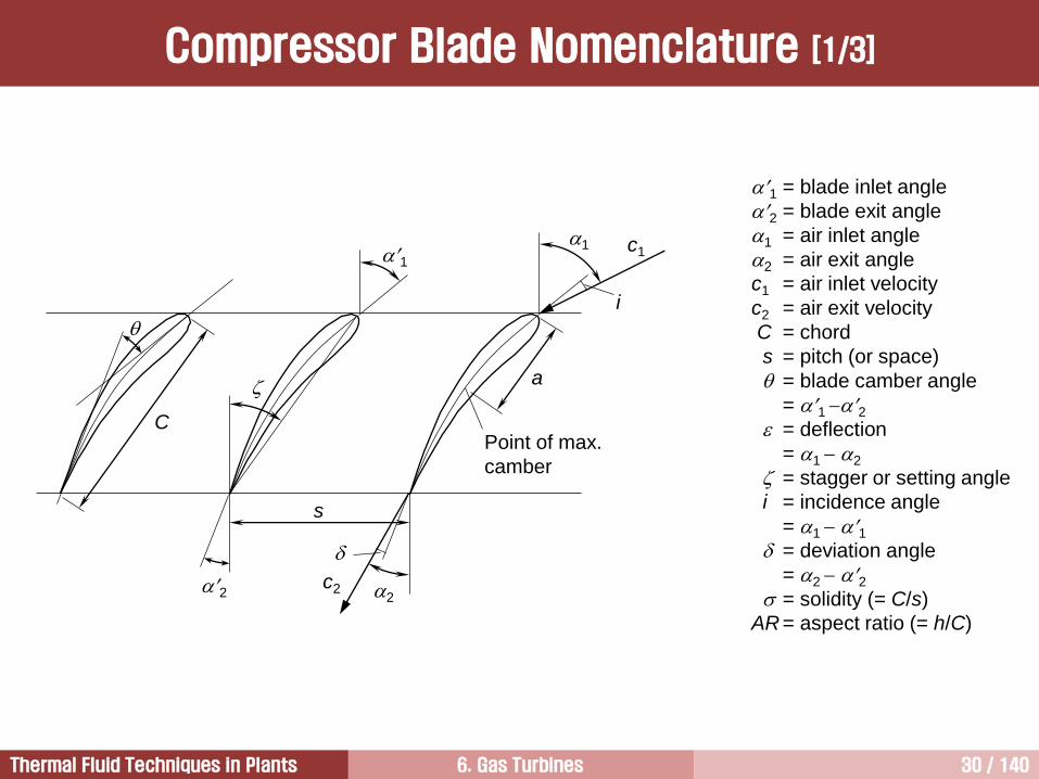
1 = blade inlet angle
2 = blade exit angle
1 = air inlet angle
2 = air exit angle
c1 = air inlet velocity
c2 = air exit velocity
C = chord
s = pitch (or space)
= blade camber angle
= 1 2 = deflection
= 1 2
= stagger or setting angle
i = incidence angle
= 1 1 = deviation angle
= 2 2 = solidity (= C/s)
AR = aspect ratio (= h/C)
1
2
1
2c2
c1
i
C
Point of max.
camber
a
s
6. Gas Turbines 31 / 140Thermal Fluid Techniques in Plants
Compressor Blade Nomenclature [2/3]
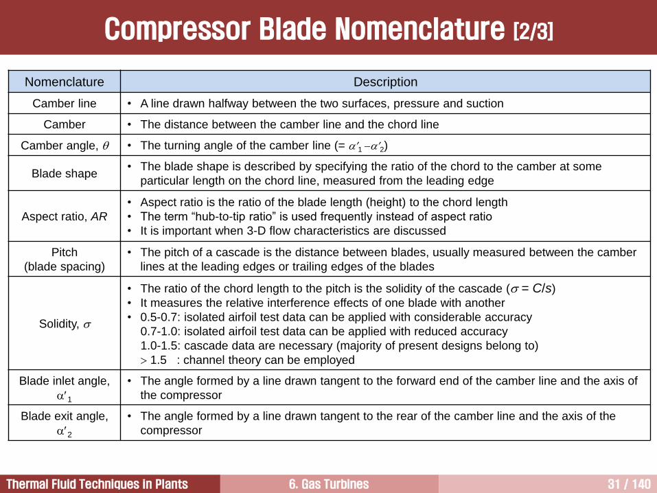
Nomenclature Description
Camber line • A line drawn halfway between the two surfaces, pressure and suction
Camber • The distance between the camber line and the chord line
Camber angle, • The turning angle of the camber line (= 1 2)
Blade shape• The blade shape is described by specifying the ratio of the chord to the camber at some
particular length on the chord line, measured from the leading edge
Aspect ratio, AR
• Aspect ratio is the ratio of the blade length (height) to the chord length
• The term “hub-to-tip ratio” is used frequently instead of aspect ratio
• It is important when 3-D flow characteristics are discussed
Pitch
(blade spacing)
• The pitch of a cascade is the distance between blades, usually measured between the camber
lines at the leading edges or trailing edges of the blades
Solidity,
• The ratio of the chord length to the pitch is the solidity of the cascade ( = C/s)
• It measures the relative interference effects of one blade with another
• 0.5-0.7: isolated airfoil test data can be applied with considerable accuracy
0.7-1.0: isolated airfoil test data can be applied with reduced accuracy
1.0-1.5: cascade data are necessary (majority of present designs belong to)
1.5 : channel theory can be employed
Blade inlet angle,
1
• The angle formed by a line drawn tangent to the forward end of the camber line and the axis of
the compressor
Blade exit angle,
2
• The angle formed by a line drawn tangent to the rear of the camber line and the axis of the
compressor
6. Gas Turbines 32 / 140Thermal Fluid Techniques in Plants
Compressor Blade Nomenclature [3/3]
Nomenclature Description
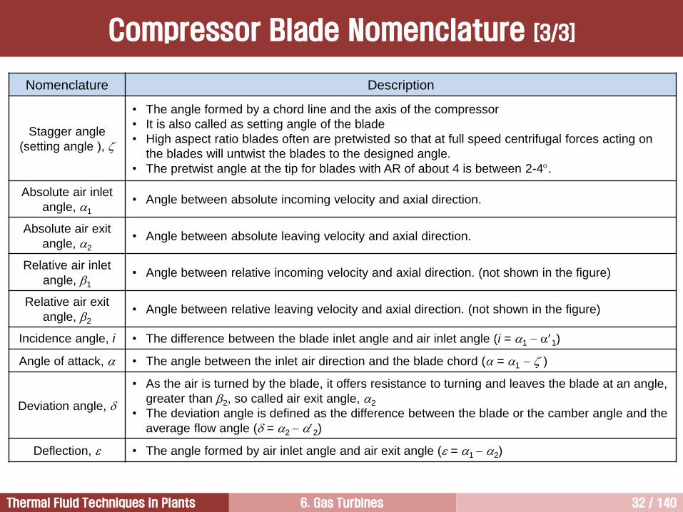
Stagger angle
(setting angle ),
• The angle formed by a chord line and the axis of the compressor
• It is also called as setting angle of the blade
• High aspect ratio blades often are pretwisted so that at full speed centrifugal forces acting on
the blades will untwist the blades to the designed angle.
• The pretwist angle at the tip for blades with AR of about 4 is between 2-4.
Absolute air inlet
angle, 1
• Angle between absolute incoming velocity and axial direction.
Absolute air exit
angle, 2
• Angle between absolute leaving velocity and axial direction.
Relative air inlet
angle, 1
• Angle between relative incoming velocity and axial direction. (not shown in the figure)
Relative air exit
angle, 2
• Angle between relative leaving velocity and axial direction. (not shown in the figure)
Incidence angle, i • The difference between the blade inlet angle and air inlet angle (i = 1 1)
Angle of attack, • The angle between the inlet air direction and the blade chord ( = 1 )
Deviation angle,
• As the air is turned by the blade, it offers resistance to turning and leaves the blade at an angle,
greater than 2, so called air exit angle, 2
• The deviation angle is defined as the difference between the blade or the camber angle and the
average flow angle ( = 2 2)
Deflection, • The angle formed by air inlet angle and air exit angle ( = 1 2)
6. Gas Turbines 33 / 140Thermal Fluid Techniques in Plants
z
r
Sta
tor
Ro
tor
Flow direction
CL
1 2 3
Velocity Triangles in Axial Flow Compressors [1/4]
6. Gas Turbines 34 / 140Thermal Fluid Techniques in Plants
Velocity Triangles in Axial Flow Compressors [2/4]
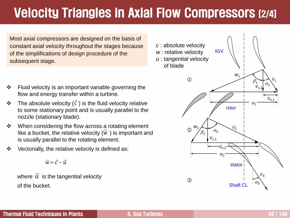
Most axial compressors are designed on the basis of
constant axial velocity throughout the stages because
of the simplifications of design procedure of the
subsequent stage.
c : absolute velocity
w : relative velocity
u : tangential velocity
of blade
c1
w1
c,1
11
vz,1
u1
w2 c2
c,2
22
vz,2
u2
c3
Shaft CL
IGV
rotor
stator
3
Fluid velocity is an important variable governing the
flow and energy transfer within a turbine.
The absolute velocity ( ) is the fluid velocity relative
to some stationary point and is usually parallel to the
nozzle (stationary blade).
When considering the flow across a rotating element
like a bucket, the relative velocity ( ) is important and
is usually parallel to the rotating element.
Vectorially, the relative velocity is defined as:
where is the tangential velocity
of the bucket.
ucw
u
w
c
6. Gas Turbines 35 / 140Thermal Fluid Techniques in Plants
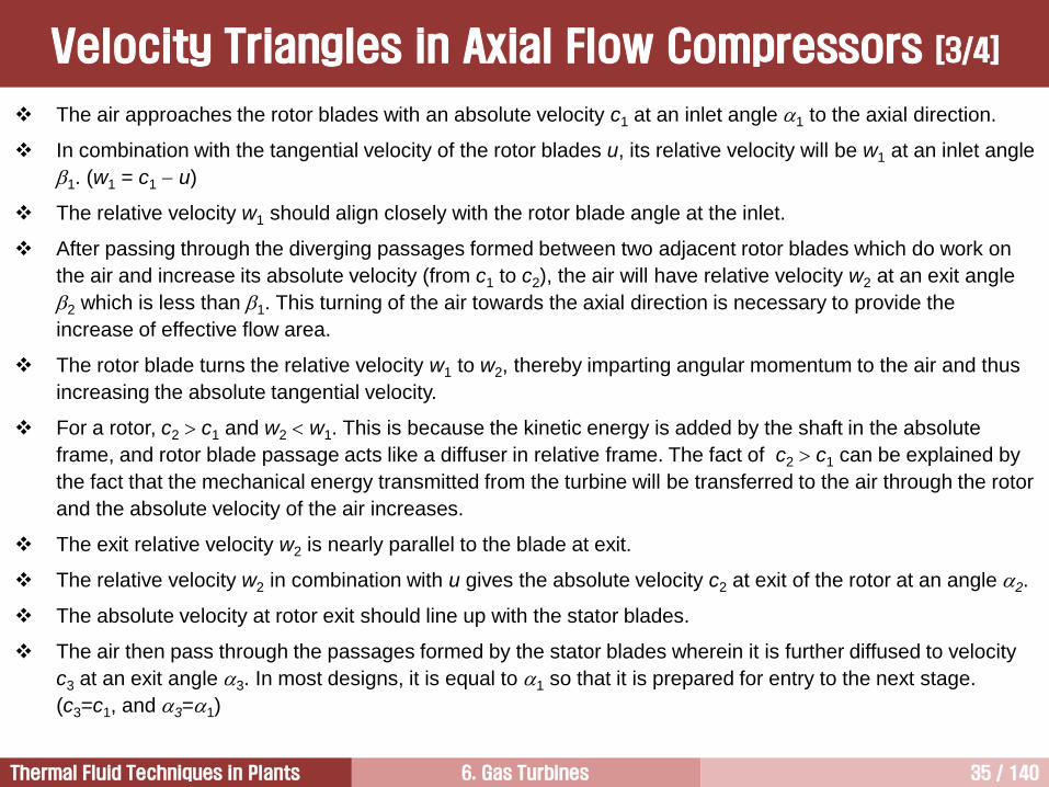
The air approaches the rotor blades with an absolute velocity c1 at an inlet angle 1 to the axial direction.
In combination with the tangential velocity of the rotor blades u, its relative velocity will be w1 at an inlet angle
1. (w1 = c1 u)
The relative velocity w1 should align closely with the rotor blade angle at the inlet.
After passing through the diverging passages formed between two adjacent rotor blades which do work on
the air and increase its absolute velocity (from c1 to c2), the air will have relative velocity w2 at an exit angle
2 which is less than 1. This turning of the air towards the axial direction is necessary to provide the
increase of effective flow area.
The rotor blade turns the relative velocity w1 to w2, thereby imparting angular momentum to the air and thus
increasing the absolute tangential velocity.
For a rotor, c2 c1 and w2 w1. This is because the kinetic energy is added by the shaft in the absolute
frame, and rotor blade passage acts like a diffuser in relative frame. The fact of c2 c1 can be explained by
the fact that the mechanical energy transmitted from the turbine will be transferred to the air through the rotor
and the absolute velocity of the air increases.
The exit relative velocity w2 is nearly parallel to the blade at exit.
The relative velocity w2 in combination with u gives the absolute velocity c2 at exit of the rotor at an angle 2.
The absolute velocity at rotor exit should line up with the stator blades.
The air then pass through the passages formed by the stator blades wherein it is further diffused to velocity
c3 at an exit angle 3. In most designs, it is equal to 1 so that it is prepared for entry to the next stage.
(c3=c1, and 3=1)
Velocity Triangles in Axial Flow Compressors [3/4]
6. Gas Turbines 36 / 140Thermal Fluid Techniques in Plants
c1
w1
u
w2
c2
u
Shaft CL
IGV Rotor 1 Stator 1
c3
w3u
Rotor 2
ho, po, To
h, p, T
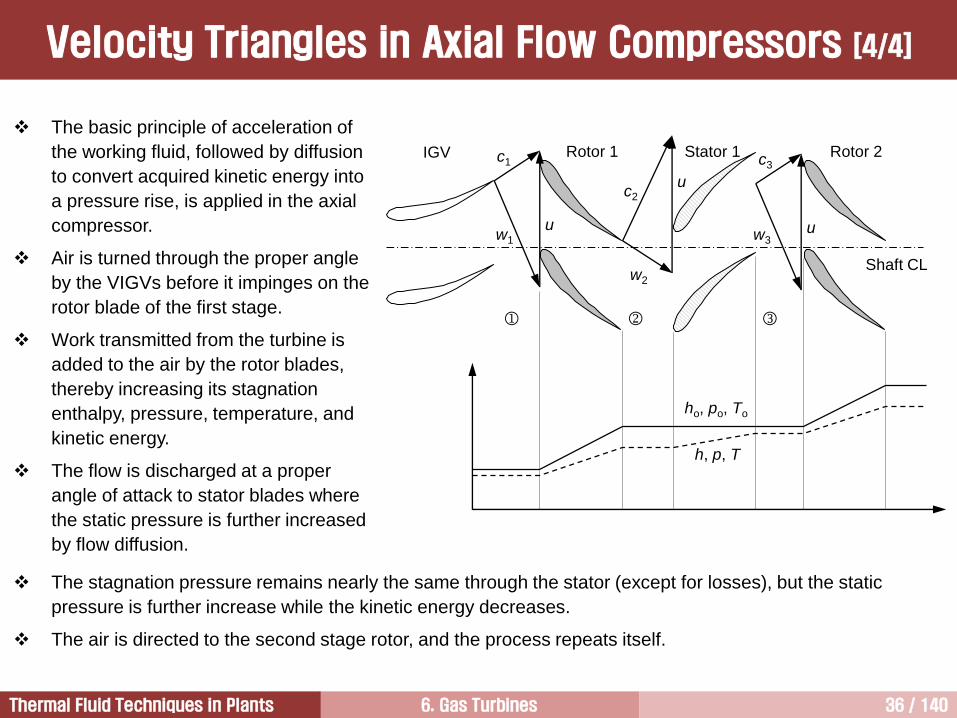
The basic principle of acceleration of
the working fluid, followed by diffusion
to convert acquired kinetic energy into
a pressure rise, is applied in the axial
compressor.
Air is turned through the proper angle
by the VIGVs before it impinges on the
rotor blade of the first stage.
Work transmitted from the turbine is
added to the air by the rotor blades,
thereby increasing its stagnation
enthalpy, pressure, temperature, and
kinetic energy.
The flow is discharged at a proper
angle of attack to stator blades where
the static pressure is further increased
by flow diffusion.
The stagnation pressure remains nearly the same through the stator (except for losses), but the static
pressure is further increase while the kinetic energy decreases.
The air is directed to the second stage rotor, and the process repeats itself.
Velocity Triangles in Axial Flow Compressors [4/4]
6. Gas Turbines 37 / 140Thermal Fluid Techniques in Plants
Variation of Velocity and Pressure
IGV
Roto
r
Ro
tor
Roto
r
Sta
tor
Sta
tor
Sta
tor
ho, po, To: total values
h, p, T: static values
c: absolute velocity
CL
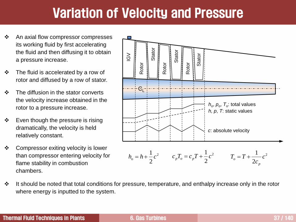
An axial flow compressor compresses
its working fluid by first accelerating
the fluid and then diffusing it to obtain
a pressure increase.
The fluid is accelerated by a row of
rotor and diffused by a row of stator.
The diffusion in the stator converts
the velocity increase obtained in the
rotor to a pressure increase.
Even though the pressure is rising
dramatically, the velocity is held
relatively constant.
Compressor exiting velocity is lower
than compressor entering velocity for
flame stability in combustion
chambers.
2
2
1chho
2
2
1cTcTc pop 2
2
1c
cTT
p
o
It should be noted that total conditions for pressure, temperature, and enthalpy increase only in the rotor
where energy is inputted to the system.
6. Gas Turbines 38 / 140Thermal Fluid Techniques in Plants
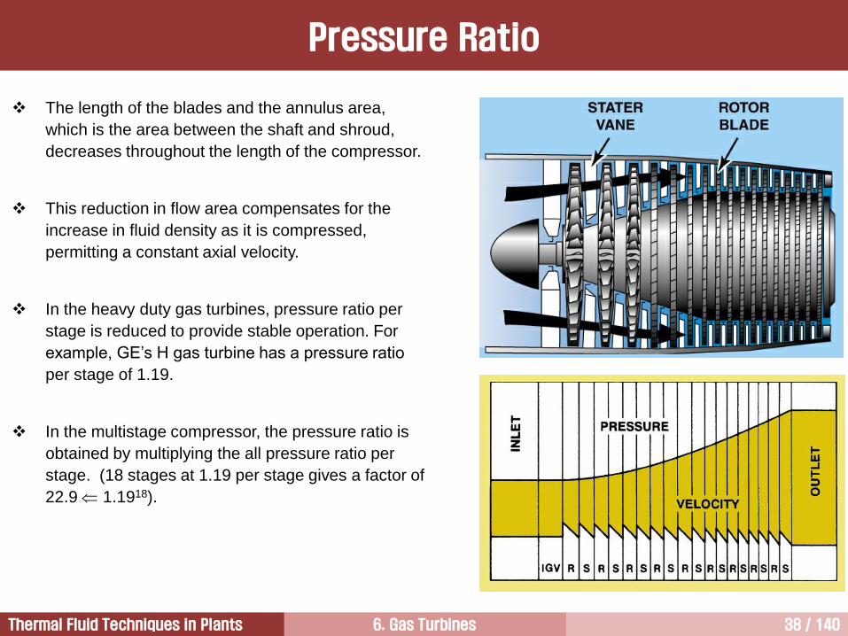
The length of the blades and the annulus area,
which is the area between the shaft and shroud,
decreases throughout the length of the compressor.
This reduction in flow area compensates for the
increase in fluid density as it is compressed,
permitting a constant axial velocity.
In the heavy duty gas turbines, pressure ratio per
stage is reduced to provide stable operation. For
example, GE’s H gas turbine has a pressure ratio
per stage of 1.19.
In the multistage compressor, the pressure ratio is
obtained by multiplying the all pressure ratio per
stage. (18 stages at 1.19 per stage gives a factor of
22.9 1.1918).
Pressure Ratio
6. Gas Turbines 39 / 140Thermal Fluid Techniques in Plants
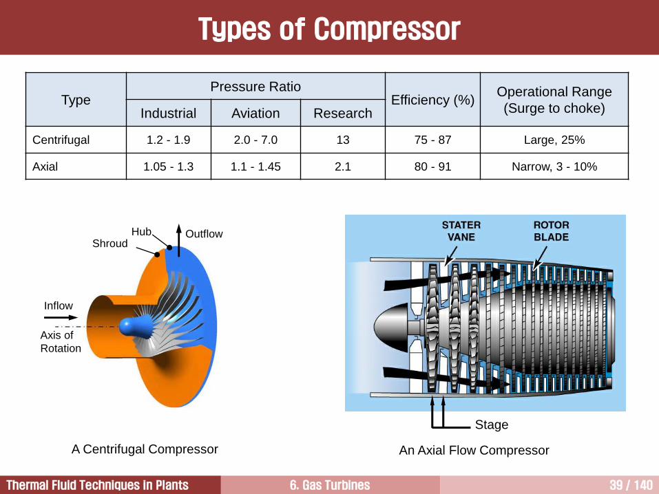
TypePressure Ratio
Efficiency (%)Operational Range
(Surge to choke)Industrial Aviation Research
Centrifugal 1.2 - 1.9 2.0 - 7.0 13 75 - 87 Large, 25%
Axial 1.05 - 1.3 1.1 - 1.45 2.1 80 - 91 Narrow, 3 - 10%
Types of Compressor
Stage
Axis of
Rotation
Inflow
OutflowShroud
Hub
A Centrifugal Compressor An Axial Flow Compressor
6. Gas Turbines 40 / 140Thermal Fluid Techniques in Plants
Compressor2
Fundamentals of Gas Turbines1
Turbine4
Combustor3
6. Gas Turbines 41 / 140Thermal Fluid Techniques in Plants
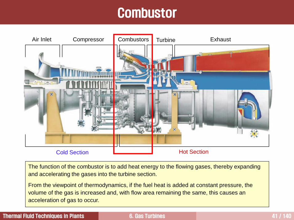
The function of the combustor is to add heat energy to the flowing gases, thereby expanding
and accelerating the gases into the turbine section.
From the viewpoint of thermodynamics, if the fuel heat is added at constant pressure, the
volume of the gas is increased and, with flow area remaining the same, this causes an
acceleration of gas to occur.
Air Inlet Compressor Combustors Turbine Exhaust
Cold Section Hot Section
Combustor
6. Gas Turbines 42 / 140Thermal Fluid Techniques in Plants
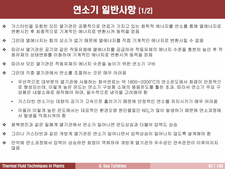
가스터빈을 포함한 모든 열기관은 공통적으로 연료가 가지고 있는 화학적 에너지를 연소를 통해 열에너지로변환시킨 후 최종적으로 기계적인 에너지로 변환시켜 동력을 얻음
그런데 열에너지는 힘의 요소가 없기 때문에 열에너지를 직접 기계적인 에너지로 변환시킬 수 없음
따라서 열기관은 공기와 같은 작동유체에 열에너지를 공급하여 작동유체의 에너지 수준을 충분히 높인 후 작동유체의 상태변화를 이용하여 기계적인 에너지로 변환시켜 동력을 얻음
따라서 모든 열기관은 작동유체의 에너지 수준을 높이기 위한 연소기 구비
그런데 각종 열기관에서 연소를 조절하는 것은 매우 어려움
• 우선적으로 대부분의 열기관에 사용하는 화석연료는 약 1800~2000°C의 연소온도에서 화염이 안정적으로 형성되는데, 이렇게 높은 온도는 연소기 구성품 소재의 용융온도를 훨씬 초과. 따라서 연소기 주요 구성품은 내열소재로 제작해야 하며, 필수적으로 냉각을 고려해야 함
• 가스터빈 연소기는 대량의 공기가 고속으로 흘러가기 때문에 안정적인 연소를 유지시키기 매우 어려움
• 아울러 이렇게 높은 온도에서는 대표적인 환경오염 원인물질인 NOx가 많이 발생하기 때문에 연소과정에서 발생을 억제시켜야 함
왕복엔진과 같은 밀폐계 열기관에서 연소가 일어나면 온도상승과 더불어 압력도 상승
그러나 가스터빈과 같은 개방계 열기관은 연소가 일어나면서 압력상승이 일어나지 않도록 설계해야 함
만약에 연소과정에서 압력이 상승하면 화염이 역류하여 개방계 열기관의 우수성인 연속운전이 이루어지지않음
연소기 일반사항 [1/2]
6. Gas Turbines 43 / 140Thermal Fluid Techniques in Plants
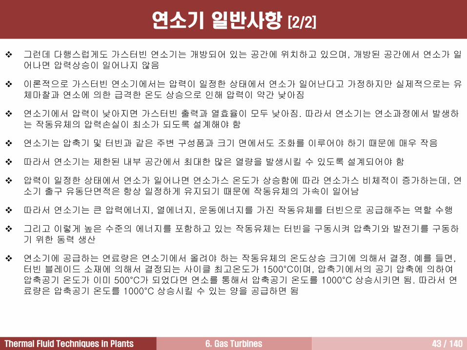
그런데 다행스럽게도 가스터빈 연소기는 개방되어 있는 공간에 위치하고 있으며, 개방된 공간에서 연소가 일어나면 압력상승이 일어나지 않음
이론적으로 가스터빈 연소기에서는 압력이 일정한 상태에서 연소가 일어난다고 가정하지만 실제적으로는 유체마찰과 연소에 의한 급격한 온도 상승으로 인해 압력이 약간 낮아짐
연소기에서 압력이 낮아지면 가스터빈 출력과 열효율이 모두 낮아짐. 따라서 연소기는 연소과정에서 발생하는 작동유체의 압력손실이 최소가 되도록 설계해야 함
연소기는 압축기 및 터빈과 같은 주변 구성품과 크기 면에서도 조화를 이루어야 하기 때문에 매우 작음
따라서 연소기는 제한된 내부 공간에서 최대한 많은 열량을 발생시킬 수 있도록 설계되어야 함
압력이 일정한 상태에서 연소가 일어나면 연소가스 온도가 상승함에 따라 연소가스 비체적이 증가하는데, 연소기 출구 유동단면적은 항상 일정하게 유지되기 때문에 작동유체의 가속이 일어남
따라서 연소기는 큰 압력에너지, 열에너지, 운동에너지를 가진 작동유체를 터빈으로 공급해주는 역할 수행
그리고 이렇게 높은 수준의 에너지를 포함하고 있는 작동유체는 터빈을 구동시켜 압축기와 발전기를 구동하기 위한 동력 생산
연소기에 공급하는 연료량은 연소기에서 올려야 하는 작동유체의 온도상승 크기에 의해서 결정. 예를 들면, 터빈 블레이드 소재에 의해서 결정되는 사이클 최고온도가 1500°C이며, 압축기에서의 공기 압축에 의하여압축공기 온도가 이미 500°C가 되었다면 연소를 통해서 압축공기 온도를 1000°C 상승시키면 됨. 따라서 연료량은 압축공기 온도를 1000°C 상승시킬 수 있는 양을 공급하면 됨
연소기 일반사항 [2/2]
6. Gas Turbines 44 / 140Thermal Fluid Techniques in Plants
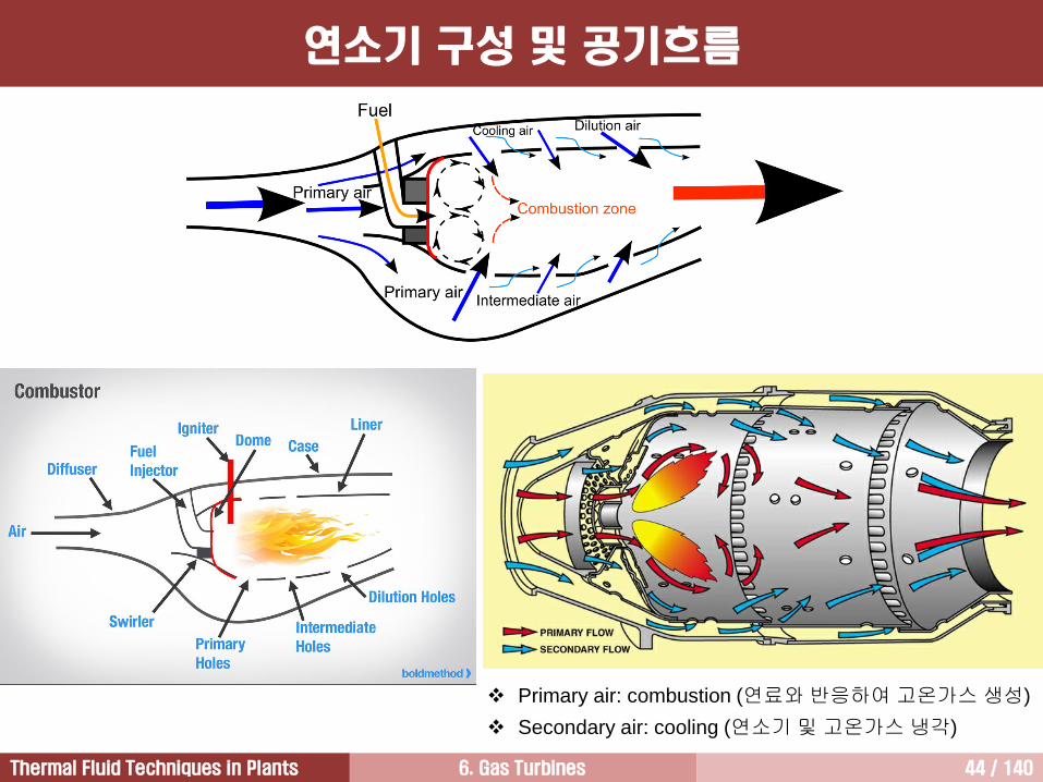
Primary air: combustion (연료와 반응하여 고온가스 생성)
Secondary air: cooling (연소기 및 고온가스 냉각)
연소기 구성 및 공기흐름
6. Gas Turbines 45 / 140Thermal Fluid Techniques in Plants
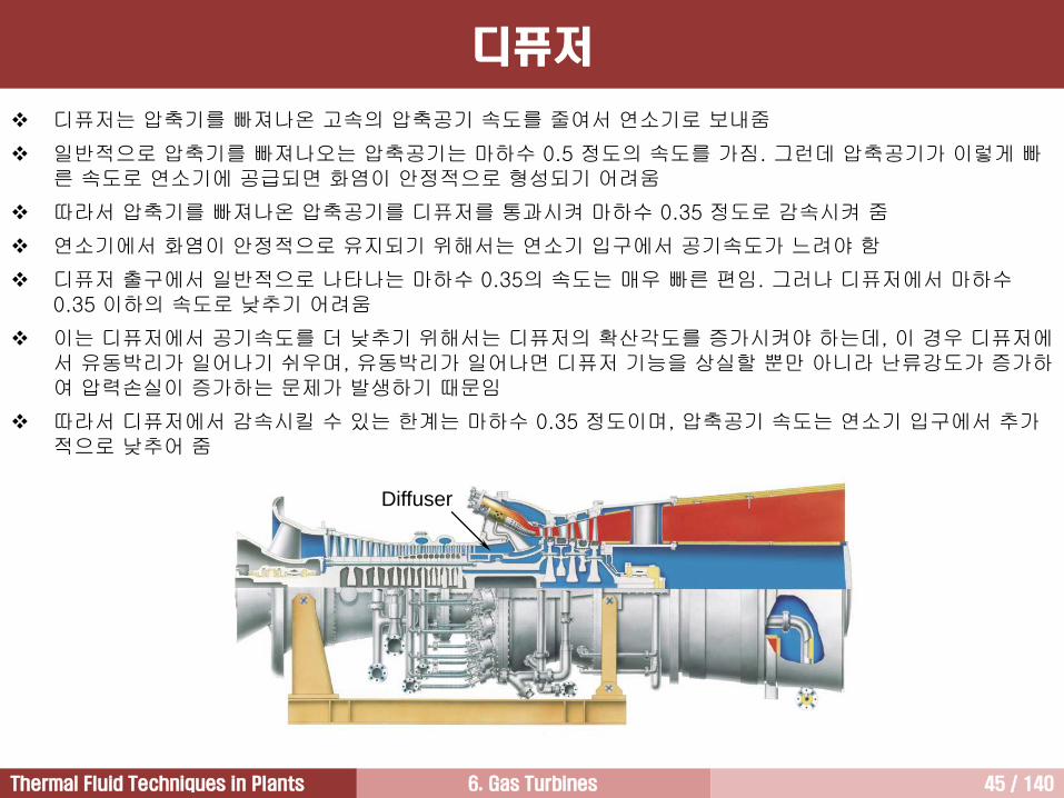
디퓨저는 압축기를 빠져나온 고속의 압축공기 속도를 줄여서 연소기로 보내줌
일반적으로 압축기를 빠져나오는 압축공기는 마하수 0.5 정도의 속도를 가짐. 그런데 압축공기가 이렇게 빠른 속도로 연소기에 공급되면 화염이 안정적으로 형성되기 어려움
따라서 압축기를 빠져나온 압축공기를 디퓨저를 통과시켜 마하수 0.35 정도로 감속시켜 줌
연소기에서 화염이 안정적으로 유지되기 위해서는 연소기 입구에서 공기속도가 느려야 함
디퓨저 출구에서 일반적으로 나타나는 마하수 0.35의 속도는 매우 빠른 편임. 그러나 디퓨저에서 마하수0.35 이하의 속도로 낮추기 어려움
이는 디퓨저에서 공기속도를 더 낮추기 위해서는 디퓨저의 확산각도를 증가시켜야 하는데, 이 경우 디퓨저에서 유동박리가 일어나기 쉬우며, 유동박리가 일어나면 디퓨저 기능을 상실할 뿐만 아니라 난류강도가 증가하여 압력손실이 증가하는 문제가 발생하기 때문임
따라서 디퓨저에서 감속시킬 수 있는 한계는 마하수 0.35 정도이며, 압축공기 속도는 연소기 입구에서 추가적으로 낮추어 줌
디퓨저
Diffuser
6. Gas Turbines 46 / 140Thermal Fluid Techniques in Plants
연료분사기 [1/2]
가스터빈 연료는 최종적으로 연료분사기를 통해 연소영역으로 분사
가스터빈에 사용하는 액체연료는 연소시키기 위해 먼저 기화시켜야 함
연료분사기(fuel injector)는 액체연료가 쉽게 기화될 수 있도록 액체연료를 무화시켜 작은 액적으로 만들어표면적을 증가시킴
액적 상태의 연료는 가스터빈 연소기에서와 같이 높은 압력의 공기 속에서 기화가 촉진되어 쉽게 연소
연료분사기 종류: 압력무화식, 공기충돌식, 증발식, 예혼합식
1) 압력무화식(pressure-atomizing) 연료분사기
• 연료에 500 psi의 높은 압력을 가하여 연료를 무화시킴
• 압력무화식 연료분사기는 매우 간단하다는 장점을 가지고 있지만 몇 가지 단점도 가지고 있다.
• 첫째, 연료계통이 고압에 견딜 수 있도록 견고하게 제작해야 하는데, 이는 연료계통 무게 증가의 원인이된다.
• 둘째, 연료 무화가 고르게 일어나지 않는 경향을 가지는데, 이는 더 많은 공해물질과 연기(smoke)를 발생시키는 불완전연소 또는 고르지 못한 연소의 원인이 된다.
2) 공기충돌식(air blast) 연료분사기
• 얇은 막 형태로 분사되는 연료(sheet of fuel)에 고속으로 공기를 충돌(blast)시켜 균일한 액적으로 연료를 무화시킴
• 연료를 무화시키기 위하여 단지 1차공기의 일부분 사용
• 공기충돌식 연료분사기를 적용하여 최초로 연소기에서 연기가 발생하는 문제 해결
• 공기충돌식 연료분사기는 압력무화식에 비해 낮은 연료압력 사용
6. Gas Turbines 47 / 140Thermal Fluid Techniques in Plants
연료분사기 [2/2]
3) 증발식 연료분사기
• 공기충돌식과 유사하며, 연료가 연소영역으로 분사되면서 1차공기와 혼합
• 그러나 연료-공기 혼합기는 연소영역 내부에 있는 튜브를 따라 흘러감
• 이 과정에서 연소영역의 열이 연료-공기 혼합기로 전달되어 연소되기 전에 연료의 일부가 증발하며, 이로 인해 연료와 공기의 혼합이 촉진
• 증발식 연료분사기를 이용하면 복사열이 줄어든 상태에서 연소가 일어나기 때문에 연소기 라이너를 보호할 수 있음
• 그러나 증발튜브는 그 내부를 흘러가는 연료에 의해 냉각되기 때문에 연료유량이 적은 경우에 수명이 짧아지는 심각한 문제를 가지고 있음
4) 예혼합(premixing) 연료분사기
• 연료가 연소영역에 도달하기 전에 공기와 미리 혼합하여 연소영역에 공급
• 연소가 일어나기 전에 연료와 공기를 미리 혼합시키면 연료와 공기를 매우 균일하게 혼합시킬 수 있으며, 이를 통해 공해물질 발생을 줄일 수 있음
• 연료와 공기를 미리 혼합하면 연료-공기 혼합기를 더 낮은 온도에서 연소시킬 수 있기 때문에 NOx 발생을 크게 줄일 수 있음
• 예혼합 연료분사기의 단점은 미리 혼합된 연료-공기 혼합기가 연소영역에 도달하기 전에 자동점화(auto-ignition)될 수 있다는 점
• 아울러 미리 혼합된 연료-공기 혼합기의 속도가 화염 전파속도보다 작은 경우 연료-공기 혼합기가 연소영역에 도달하기 전에 화염이 역방향으로 전파되어 연소. 이를 플래시백(flashback)이라 함
• 자동점화와 플래시백이 일어나면 연소기는 심각한 손상을 입게 됨
6. Gas Turbines 48 / 140Thermal Fluid Techniques in Plants
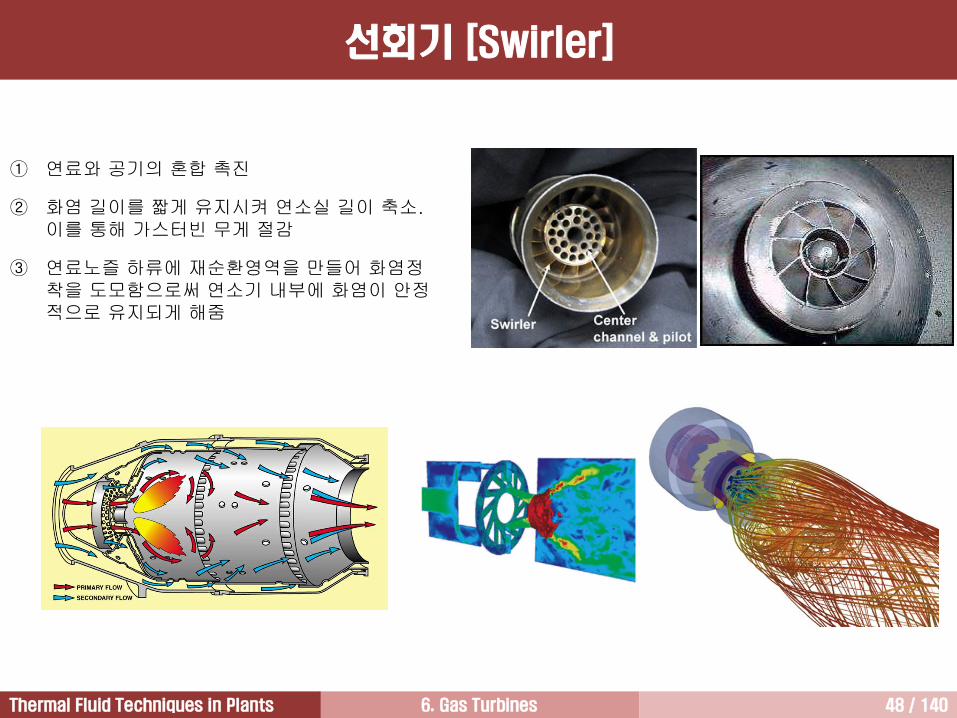
선회기 [Swirler]
① 연료와 공기의 혼합 촉진
② 화염 길이를 짧게 유지시켜 연소실 길이 축소. 이를 통해 가스터빈 무게 절감
③ 연료노즐 하류에 재순환영역을 만들어 화염정착을 도모함으로써 연소기 내부에 화염이 안정적으로 유지되게 해줌
6. Gas Turbines 49 / 140Thermal Fluid Techniques in Plants
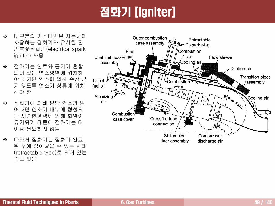
점화기 [Igniter]
대부분의 가스터빈은 자동차에사용하는 점화기와 유사한 전기불꽃점화기(electrical spark igniter) 사용
점화기는 연료와 공기가 혼합되어 있는 연소영역에 위치해야 하지만 연소에 의해 손상 받지 않도록 연소기 상류에 위치해야 함
점화기에 의해 일단 연소가 일어나면 연소기 내부에 형성되는 재순환영역에 의해 화염이유지되기 때문에 점화기는 더이상 필요하지 않음
따라서 점화기는 점화가 완료된 후에 집어넣을 수 있는 형태(retractable type)로 되어 있는것도 있음
6. Gas Turbines 50 / 140Thermal Fluid Techniques in Plants
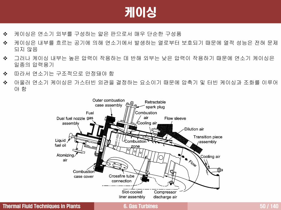
케이싱은 연소기 외부를 구성하는 얇은 판으로서 매우 단순한 구성품
케이싱은 내부를 흐르는 공기에 의해 연소기에서 발생하는 열로부터 보호되기 때문에 열적 성능은 전혀 문제되지 않음
그러나 케이싱 내부는 높은 압력이 작용하는 데 반해 외부는 낮은 압력이 작용하기 때문에 연소기 케이싱은일종의 압력용기
따라서 연소기는 구조적으로 안정돼야 함
아울러 연소기 케이싱은 가스터빈 외관을 결정하는 요소이기 때문에 압축기 및 터빈 케이싱과 조화를 이루어야 함
케이싱
6. Gas Turbines 51 / 140Thermal Fluid Techniques in Plants
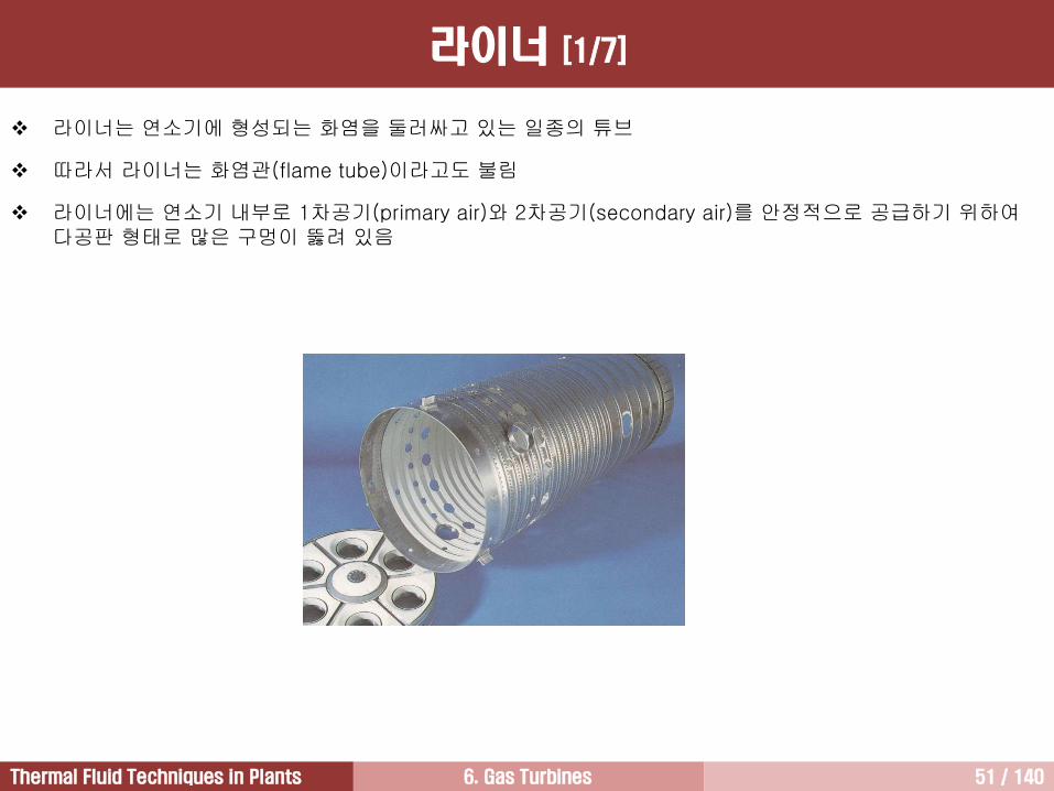
라이너 [1/7]
라이너는 연소기에 형성되는 화염을 둘러싸고 있는 일종의 튜브
따라서 라이너는 화염관(flame tube)이라고도 불림
라이너에는 연소기 내부로 1차공기(primary air)와 2차공기(secondary air)를 안정적으로 공급하기 위하여다공판 형태로 많은 구멍이 뚫려 있음
6. Gas Turbines 52 / 140Thermal Fluid Techniques in Plants
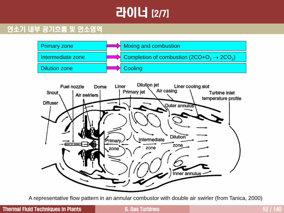
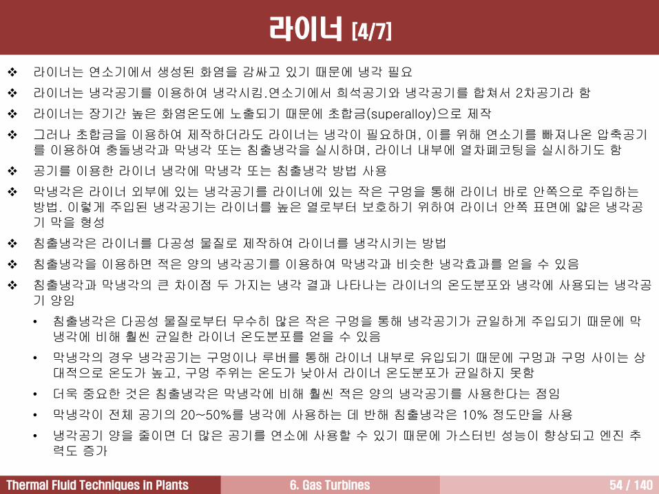
A representative flow pattern in an annular combustor with double air swirler (from Tanica, 2000)
Primary zone
Intermediate zone
Dilution zone
Mixing and combustion
Completion of combustion (2CO+O2 2CO2)
Cooling
연소기 내부 공기흐름 및 연소영역
라이너 [2/7]
6. Gas Turbines 53 / 140Thermal Fluid Techniques in Plants
연료가 분사되는 연료노즐 바로 하류에 1차영역(primary zone) 형성
1차영역에서는 연료와 공기의 혼합이 일어나면서 연소가 일어남
연료와 혼합되어 연소에 사용되는 공기를 1차공기라 함
1차공기의 일부는 선회기를 통해 연소기 중앙부로 공급되며, 일부는 라이너 상류에 있는 작은 구멍을 통해반경방향으로 공급. 1차공기 양은 압축기를 빠져나온 전체 공기의 약 1/3이하 정도
2차영역(secondary zone, or intermediate zone)에서는 계속해서 연소가 진행
가스터빈 연료는 탄소와 수소가 결합되어 있는 탄화수소. 탄소는 연소과정에서 일차적으로 산화되어 일산화탄소를 형성. 이렇게 생성된 일산화탄소는 2차영역에서 다시 산소와 결합하여 이산화탄소가 되면서 탄소의연소 완료.
따라서 탄소는 폭발적으로 연소하는 수소에 비해 연소가 느리게 진행. 그러므로 연료의 연소는 2차영역에서종료되며, 1차영역과 2차영역을 합친 길이는 연소기 전체 길이의 약 75%를 차지
연소기에서 생성된 배기가스 온도는 터빈으로 직접 보내기에는 너무 높음
따라서 2차영역 하류에 있는 희석영역(dilution zone, or tertiary zone)에 추가적으로 압축공기를 공급하여배기가스와 혼합시켜 배기가스 온도를 터빈에 적합한 온도로 낮추어 줌
희석공기는 라이너 하류에 있는 구멍을 통해 연소기로 유입
최근에 개발된 가스터빈은 성능을 향상시키기 위하여 증가된 TIT를 적용함에 따라 더 적은 양의 희석공기를사용. 이렇게 줄어든 희석공기는 다시 연료의 연소에 사용할 수 있기 때문에 가스터빈 성능 더욱 향상되며, 추력 증가.
라이너 [3/7]
6. Gas Turbines 54 / 140Thermal Fluid Techniques in Plants
라이너는 연소기에서 생성된 화염을 감싸고 있기 때문에 냉각 필요
라이너는 냉각공기를 이용하여 냉각시킴.연소기에서 희석공기와 냉각공기를 합쳐서 2차공기라 함
라이너는 장기간 높은 화염온도에 노출되기 때문에 초합금(superalloy)으로 제작
그러나 초합금을 이용하여 제작하더라도 라이너는 냉각이 필요하며, 이를 위해 연소기를 빠져나온 압축공기를 이용하여 충돌냉각과 막냉각 또는 침출냉각을 실시하며, 라이너 내부에 열차폐코팅을 실시하기도 함
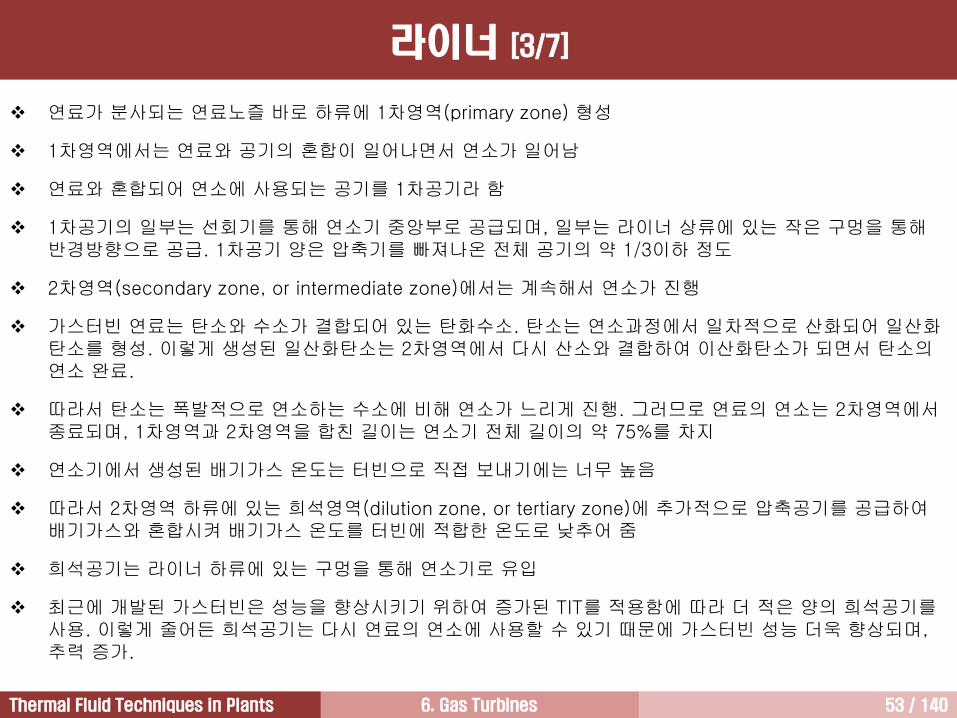
공기를 이용한 라이너 냉각에 막냉각 또는 침출냉각 방법 사용
막냉각은 라이너 외부에 있는 냉각공기를 라이너에 있는 작은 구멍을 통해 라이너 바로 안쪽으로 주입하는방법. 이렇게 주입된 냉각공기는 라이너를 높은 열로부터 보호하기 위하여 라이너 안쪽 표면에 얇은 냉각공기 막을 형성
침출냉각은 라이너를 다공성 물질로 제작하여 라이너를 냉각시키는 방법
침출냉각을 이용하면 적은 양의 냉각공기를 이용하여 막냉각과 비슷한 냉각효과를 얻을 수 있음
침출냉각과 막냉각의 큰 차이점 두 가지는 냉각 결과 나타나는 라이너의 온도분포와 냉각에 사용되는 냉각공기 양임
• 침출냉각은 다공성 물질로부터 무수히 많은 작은 구멍을 통해 냉각공기가 균일하게 주입되기 때문에 막냉각에 비해 훨씬 균일한 라이너 온도분포를 얻을 수 있음
• 막냉각의 경우 냉각공기는 구멍이나 루버를 통해 라이너 내부로 유입되기 때문에 구멍과 구멍 사이는 상대적으로 온도가 높고, 구멍 주위는 온도가 낮아서 라이너 온도분포가 균일하지 못함
• 더욱 중요한 것은 침출냉각은 막냉각에 비해 훨씬 적은 양의 냉각공기를 사용한다는 점임
• 막냉각이 전체 공기의 20~50%를 냉각에 사용하는 데 반해 침출냉각은 10% 정도만을 사용
• 냉각공기 양을 줄이면 더 많은 공기를 연소에 사용할 수 있기 때문에 가스터빈 성능이 향상되고 엔진 추력도 증가
라이너 [4/7]
6. Gas Turbines 55 / 140Thermal Fluid Techniques in Plants
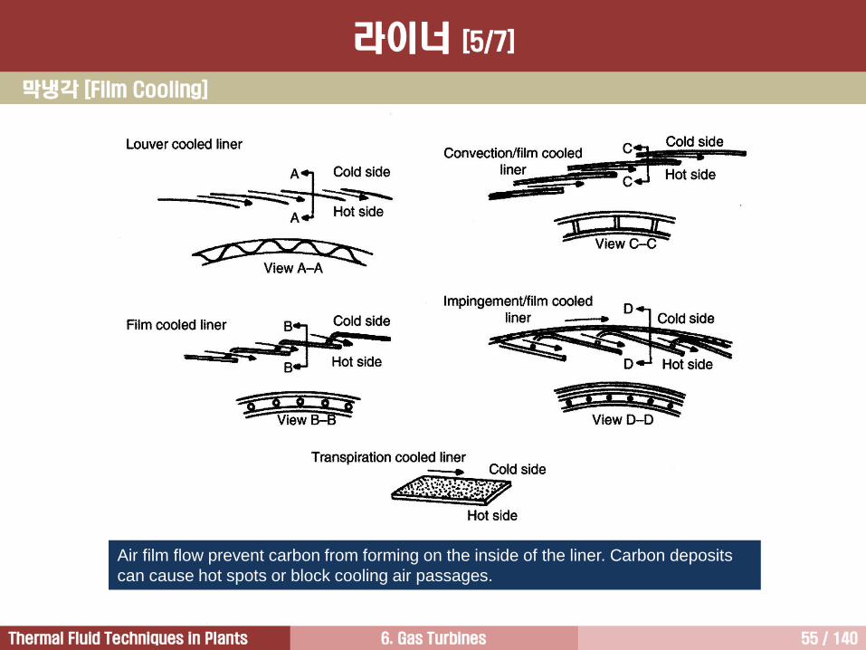
Air film flow prevent carbon from forming on the inside of the liner. Carbon deposits
can cause hot spots or block cooling air passages.
막냉각 [Film Cooling]
라이너 [5/7]
6. Gas Turbines 56 / 140Thermal Fluid Techniques in Plants
막냉각 및 충돌냉각
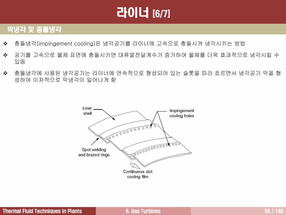
충돌냉각(impingement cooling)은 냉각공기를 라이너에 고속으로 충돌시켜 냉각시키는 방법
공기를 고속으로 물체 표면에 충돌시키면 대류열전달계수가 증가하여 물체를 더욱 효과적으로 냉각시킬 수있음
충돌냉각에 사용된 냉각공기는 라이너에 연속적으로 형성되어 있는 슬롯을 따라 흐르면서 냉각공기 막을 형성하여 이차적으로 막냉각이 일어나게 함
라이너 [6/7]
6. Gas Turbines 57 / 140Thermal Fluid Techniques in Plants
열차폐코팅
Hot gases
Thermal Barrier Coating
Bond Coat
Base
Material
Cooling gases
1400C12001000
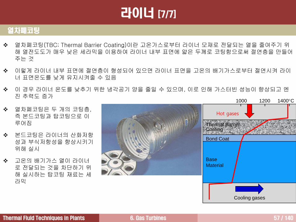
열차폐코팅(TBC; Thermal Barrier Coating)이란 고온가스로부터 라이너 모재로 전달되는 열을 줄여주기 위해 열전도도가 매우 낮은 세라믹을 이용하여 라이너 내부 표면에 얇은 두께로 코팅함으로써 절연층을 만들어주는 것
이렇게 라이너 내부 표면에 절연층이 형성되어 있으면 라이너 표면을 고온의 배기가스로부터 절연시켜 라이너 표면온도를 낮게 유지시켜줄 수 있음
이 경우 라이너 온도를 낮추기 위한 냉각공기 양을 줄일 수 있으며, 이로 인해 가스터빈 성능이 향상되고 엔진 추력도 증가
열차폐코팅은 두 개의 코팅층, 즉 본드코팅과 탑코팅으로 이루어짐
본드코팅은 라이너의 산화저항성과 부식저항성을 향상시키기위해 실시
고온의 배기가스 열이 라이너로 전달되는 것을 차단하기 위해 실시하는 탑코팅 재료는 세라믹
라이너 [7/7]
6. Gas Turbines 58 / 140Thermal Fluid Techniques in Plants
1) 모든 운전조건에서 연소효율이 높아야 한다.
2) 공해물질 배출이 최소가 되어야 한다.
3) 연소기에서 발생하는 압력손실이 작아야 한다.
4) 모든 운전조건에서 연소가 안정적으로 이루어져야 한다.
5) 거친 연소나 맥동 없이 연소가 부드럽게 일어나야 한다.
6) 터빈 수명을 보장하기 위해 온도변화가 작아야 한다. 급격한 온도구배는 연소기 라이너 비틀림과 크랙의 원인이 되기 때문에 반드시 피해야 한다.
7) 연소기 길이와 직경이 가스터빈 외관 형상에 적합해야 한다.
8) 제작비가 저렴해야 하며, 유지보수가 쉬워야 한다.
9) 어떤 운전환경에서도 카본 디포짓(carbon deposits)이 형성되지 말아야 한다. 카본 디포짓이 형성되면 연소기 라이너가 비틀어질 수 있으며, 연소기 내부 유동 패턴을 달라지기 때문에 압력손실이 증가한다.
연소기 구비조건
6. Gas Turbines 59 / 140Thermal Fluid Techniques in Plants
연소강도
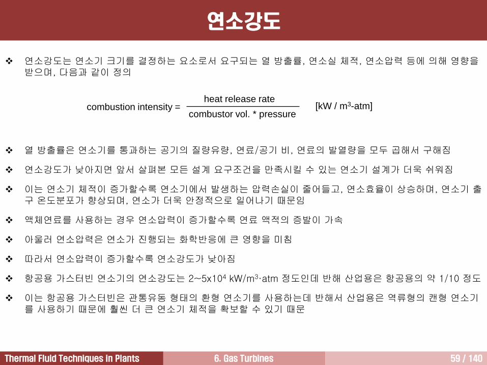
연소강도는 연소기 크기를 결정하는 요소로서 요구되는 열 방출률, 연소실 체적, 연소압력 등에 의해 영향을받으며, 다음과 같이 정의
열 방출률은 연소기를 통과하는 공기의 질량유량, 연료/공기 비, 연료의 발열량을 모두 곱해서 구해짐
연소강도가 낮아지면 앞서 살펴본 모든 설계 요구조건을 만족시킬 수 있는 연소기 설계가 더욱 쉬워짐
이는 연소기 체적이 증가할수록 연소기에서 발생하는 압력손실이 줄어들고, 연소효율이 상승하며, 연소기 출구 온도분포가 향상되며, 연소가 더욱 안정적으로 일어나기 때문임
액체연료를 사용하는 경우 연소압력이 증가할수록 연료 액적의 증발이 가속
아울러 연소압력은 연소가 진행되는 화학반응에 큰 영향을 미침
따라서 연소압력이 증가할수록 연소강도가 낮아짐
항공용 가스터빈 연소기의 연소강도는 2~5x10⁴ kW/m3·atm 정도인데 반해 산업용은 항공용의 약 1/10 정도
이는 항공용 가스터빈은 관통유동 형태의 환형 연소기를 사용하는데 반해서 산업용은 역류형의 캔형 연소기를 사용하기 때문에 훨씬 더 큰 연소기 체적을 확보할 수 있기 때문
combustion intensity = heat release rate
combustor vol. * pressure[kW / m3-atm]
6. Gas Turbines 60 / 140Thermal Fluid Techniques in Plants
연소효율
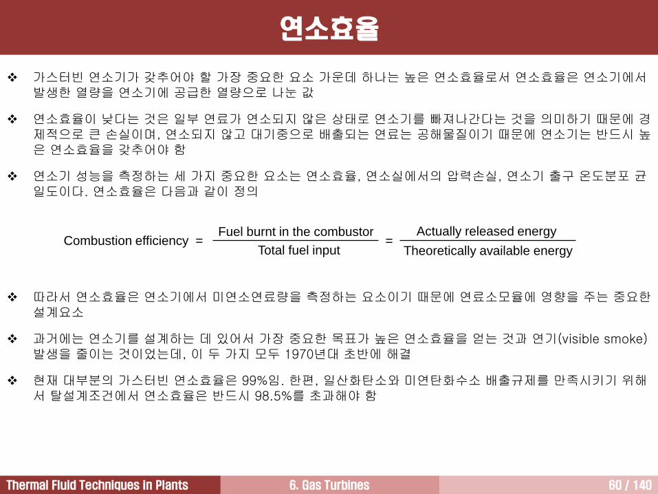
가스터빈 연소기가 갖추어야 할 가장 중요한 요소 가운데 하나는 높은 연소효율로서 연소효율은 연소기에서발생한 열량을 연소기에 공급한 열량으로 나눈 값
연소효율이 낮다는 것은 일부 연료가 연소되지 않은 상태로 연소기를 빠져나간다는 것을 의미하기 때문에 경제적으로 큰 손실이며, 연소되지 않고 대기중으로 배출되는 연료는 공해물질이기 때문에 연소기는 반드시 높은 연소효율을 갖추어야 함
연소기 성능을 측정하는 세 가지 중요한 요소는 연소효율, 연소실에서의 압력손실, 연소기 출구 온도분포 균일도이다. 연소효율은 다음과 같이 정의
따라서 연소효율은 연소기에서 미연소연료량을 측정하는 요소이기 때문에 연료소모율에 영향을 주는 중요한설계요소
과거에는 연소기를 설계하는 데 있어서 가장 중요한 목표가 높은 연소효율을 얻는 것과 연기(visible smoke) 발생을 줄이는 것이었는데, 이 두 가지 모두 1970년대 초반에 해결
현재 대부분의 가스터빈 연소효율은 99%임. 한편, 일산화탄소와 미연탄화수소 배출규제를 만족시키기 위해서 탈설계조건에서 연소효율은 반드시 98.5%를 초과해야 함
= Actually released energy
Theoretically available energyCombustion efficiency =
Fuel burnt in the combustor
Total fuel input
6. Gas Turbines 61 / 140Thermal Fluid Techniques in Plants
1
1,
2,
21
o
o
T
TKKPLF
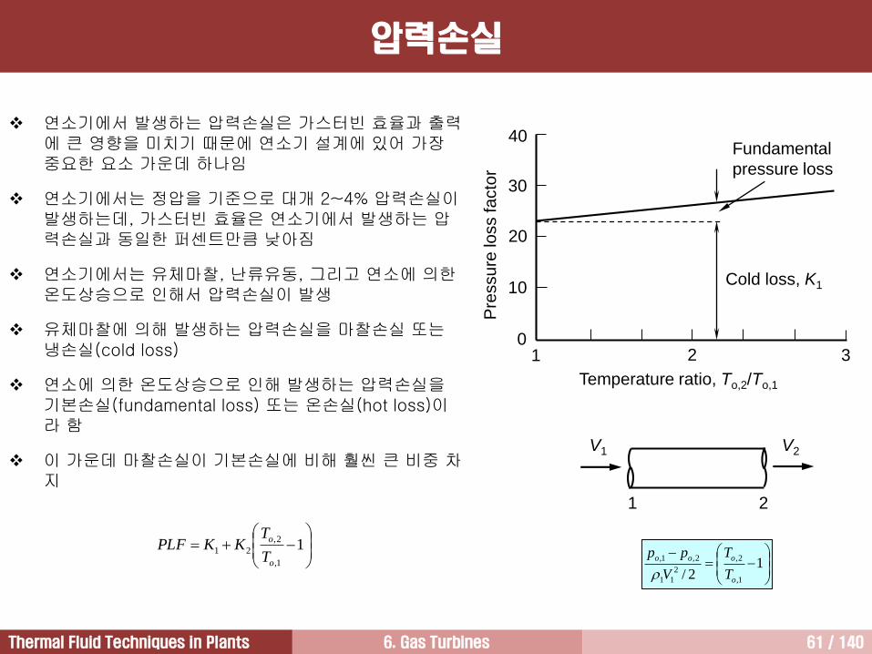
연소기에서 발생하는 압력손실은 가스터빈 효율과 출력에 큰 영향을 미치기 때문에 연소기 설계에 있어 가장중요한 요소 가운데 하나임
연소기에서는 정압을 기준으로 대개 2~4% 압력손실이발생하는데, 가스터빈 효율은 연소기에서 발생하는 압력손실과 동일한 퍼센트만큼 낮아짐
연소기에서는 유체마찰, 난류유동, 그리고 연소에 의한온도상승으로 인해서 압력손실이 발생
유체마찰에 의해 발생하는 압력손실을 마찰손실 또는냉손실(cold loss)
연소에 의한 온도상승으로 인해 발생하는 압력손실을기본손실(fundamental loss) 또는 온손실(hot loss)이라 함
이 가운데 마찰손실이 기본손실에 비해 훨씬 큰 비중 차지
1 2 30
40
30
20
10
Temperature ratio, To,2/To,1
Pre
ssu
re lo
ss fa
cto
r
Cold loss, K1
Fundamental
pressure loss
V1 V2
1 2
1
2/ 1,
2,
2
11
2,1,
o
ooo
T
T
V
pp
압력손실
6. Gas Turbines 62 / 140Thermal Fluid Techniques in Plants
Tip
Hub
Temperature
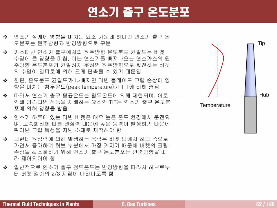
연소기 설계에 영향을 미치는 요소 가운데 하나인 연소기 출구 온도분포는 원주방향과 반경방향으로 구분
가스터빈 연소기 출구에서의 원주방향 온도분포 균일도는 버켓수명에 큰 영향을 미침. 이는 연소기를 빠져나오는 연소가스의 원주방향 온도분포가 균일하지 못하면 원주방향으로 회전하는 버켓의 수명이 열피로에 의해 크게 단축될 수 있기 때문임
한편, 온도분포 균일도가 나빠지면 터빈 블레이드 크립 손상에 영향을 미치는 첨두온도(peak temperature)가 TIT에 비해 커짐
따라서 연소기 출구 평균온도는 첨두온도에 의해 제한되며, 이로인해 가스터빈 성능을 지배하는 요소인 TIT는 연소기 출구 온도분포에 의해 영향을 받음
연소기 하류에 있는 터빈 버켓은 매우 높은 온도 환경에서 운전되며, 고속회전에 따른 원심력 때문에 높은 응력이 발생하기 때문에뛰어난 크립 특성을 지닌 소재로 제작해야 함
그런데 원심력에 의해 발생하는 응력은 버켓 팁에서 허브 쪽으로가면서 증가하여 허브 부분에서 가장 커지기 때문에 버켓의 크립손상을 최소화하기 위해 연소기 출구 온도분포는 반경방향을 따라 제어되어야 함
일반적으로 연소기 출구 첨두온도는 반경방향을 따라서 허브로부터 버켓 길이의 2/3 지점에 나타나도록 함
연소기 출구 온도분포
6. Gas Turbines 63 / 140Thermal Fluid Techniques in Plants
가스터빈 연소실에서 연소가 진행되는 과정에서 원치 않는 공해물질 발생
현재 법적으로 배출이 규제되고 있는 네 가지 공해물질: 미연탄화수소(미연소 연료), 연기(smoke, 탄소입자), 일산화탄소, NOx
이런 공해물질 생성에 영향을 미치는 요소는 연소기 내부에 형성되는 압력 및 온도와 연소시간
연소기 1차영역의 연료농후 영역에서는 연료가 연소하면서 일산화탄소와 연기가 생성되며, 이들은 2차영역에서 계속해서 연소되어 독성이 없는 이산화탄소가 됨
미연탄화수소 역시 2차영역에서 완전연소시켜 발생을 줄일 수 있음
NOx는 연소에 의한 고온환경에서 생성되며, 고온에서의 체류시간이 길어질수록 발생이 증가
따라서 NOx 발생을 줄이기 위해서는 가능한 빨리 화염을 냉각시키는 것이 바람직하며, 연소시간을 짧게 유지해야 함
현재는 연소기 설계기술의 지속적인 향상으로 과거에 비해 공해물질 배출이 훨씬 줄어들었음
공해물질 배출
6. Gas Turbines 64 / 140Thermal Fluid Techniques in Plants
캔형 연소기
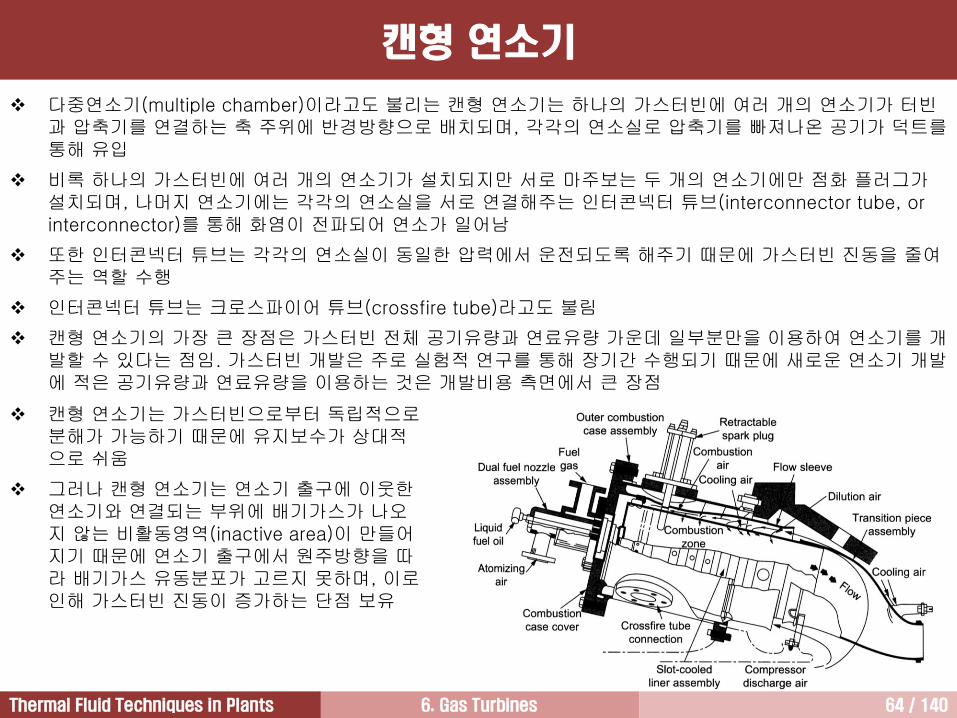
다중연소기(multiple chamber)이라고도 불리는 캔형 연소기는 하나의 가스터빈에 여러 개의 연소기가 터빈과 압축기를 연결하는 축 주위에 반경방향으로 배치되며, 각각의 연소실로 압축기를 빠져나온 공기가 덕트를통해 유입
비록 하나의 가스터빈에 여러 개의 연소기가 설치되지만 서로 마주보는 두 개의 연소기에만 점화 플러그가설치되며, 나머지 연소기에는 각각의 연소실을 서로 연결해주는 인터콘넥터 튜브(interconnector tube, or interconnector)를 통해 화염이 전파되어 연소가 일어남
또한 인터콘넥터 튜브는 각각의 연소실이 동일한 압력에서 운전되도록 해주기 때문에 가스터빈 진동을 줄여주는 역할 수행
인터콘넥터 튜브는 크로스파이어 튜브(crossfire tube)라고도 불림
캔형 연소기의 가장 큰 장점은 가스터빈 전체 공기유량과 연료유량 가운데 일부분만을 이용하여 연소기를 개발할 수 있다는 점임. 가스터빈 개발은 주로 실험적 연구를 통해 장기간 수행되기 때문에 새로운 연소기 개발에 적은 공기유량과 연료유량을 이용하는 것은 개발비용 측면에서 큰 장점
캔형 연소기는 가스터빈으로부터 독립적으로분해가 가능하기 때문에 유지보수가 상대적으로 쉬움
그러나 캔형 연소기는 연소기 출구에 이웃한연소기와 연결되는 부위에 배기가스가 나오지 않는 비활동영역(inactive area)이 만들어지기 때문에 연소기 출구에서 원주방향을 따라 배기가스 유동분포가 고르지 못하며, 이로인해 가스터빈 진동이 증가하는 단점 보유
6. Gas Turbines 65 / 140Thermal Fluid Techniques in Plants
환형 연소기는 연소실 형상이 원주방향을 따라 막힘없는 환형
환형 연소기는 캔형 연소기와 달리 하나의 라이너와 하나의 케이싱으로 구성
장점
• 동일한 출력과 직경을 가지는 캔형 연소기에 비해 75% 정도의 길이를 가지기 때문에 가스터빈 무게와 가격이 크기 줄어듬
• 캔형 연소기에 비해 라이너 표면적이 작기 때문에 더 적은 냉각공기를 필요로 하며, 이로 인해 가스터빈열효율과 출력이 향상. 이는 라이너 표면적이 작아지면 연소기에서 발생하는 압력손실 크기가 줄어들 뿐만 아니라 연소에 더 많은 압축공기를 사용할 수 있기 때문임
• 화염전파에 따른 문제가 없음
• 연소기 출구에서 원주방향 온도분포 및 속도분포가 캔형 연소기에 비해 균일하기 때문에 가스터빈 진동이 줄어들고 터빈 블레이드 수명이 길어짐
단점
• 다수의 연료노즐을 사용하더라도 연소기 출구에서 균일한 온도분포를 얻기 힘듦
• 캔형 연소기에 비해 구조적으로 취약하기 때문에 고온상태에서 라이너에 좌굴이 발생할 가능성이 높음
• 환형 연소기를 개발하기 위해서는 가스터빈 전출력에 해당하는 질량유량의 압축공기를 공급하기 위한 방대한 실험설비 구축이 요구되며, 많은 연료가 필요하기 때문에 과도한 개발비용 소요
• 분해하기 어렵기 때문에 유지보수가 어려움
환형 연소기 [1/2]
6. Gas Turbines 66 / 140Thermal Fluid Techniques in Plants
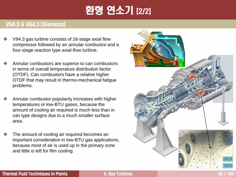
V94.3 gas turbine consists of 16-stage axial flow
compressor followed by an annular combustor and a
four-stage reaction type axial-flow turbine.
Annular combustors are superior to can combustors
in terms of overall temperature distribution factor
(OTDF). Can combustors have a relative higher
OTDF that may result in thermo-mechanical fatigue
problems.
Annular combustor popularity increases with higher
temperatures or low-BTU gases, because the
amount of cooling air required is much less than in
can type designs due to a much smaller surface
area.
The amount of cooling air required becomes an
important consideration in low-BTU gas applications,
because most of air is used up in the primary zone
and little is left for film cooling.
V94.3 & V84.3 [Siemens]
환형 연소기 [2/2]

6. Gas Turbines 67 / 140Thermal Fluid Techniques in Plants
Catalytic combustorDiffusion combustor Wet combustor DLN combustor
Steam or water injection Inclusion of catalyst
Single fuel nozzle Multiple fuel nozzle
Reduced NOx emission Low NOx emission Near zero NOx emission
Premix fuel and air
before combustion
Fuel injectorSpark
plugD
iese
l e
ng
ine
Sp
ark
ig
nitio
n e
ng
ine
Design Change of Combustors
6. Gas Turbines 68 / 140Thermal Fluid Techniques in Plants
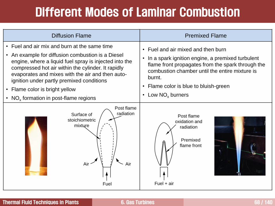
Diffusion Flame Premixed Flame
• Fuel and air mix and burn at the same time
• An example for diffusion combustion is a Diesel
engine, where a liquid fuel spray is injected into the
compressed hot air within the cylinder. It rapidly
evaporates and mixes with the air and then auto-
ignition under partly premixed conditions
• Flame color is bright yellow
• NOx formation in post-flame regions
• Fuel and air mixed and then burn
• In a spark ignition engine, a premixed turbulent
flame front propagates from the spark through the
combustion chamber until the entire mixture is
burnt.
• Flame color is blue to bluish-green
• Low NOx burners
Different Modes of Laminar Combustion
Post flame
oxidation and
radiation
Premixed
flame front
Fuel + airFuel
Post flame
radiationSurface of
stoichiometric
mixture
AirAir
6. Gas Turbines 69 / 140Thermal Fluid Techniques in Plants
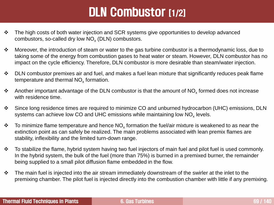
The high costs of both water injection and SCR systems give opportunities to develop advanced
combustors, so-called dry low NOx (DLN) combustors.
Moreover, the introduction of steam or water to the gas turbine combustor is a thermodynamic loss, due to
taking some of the energy from combustion gases to heat water or steam. However, DLN combustor has no
impact on the cycle efficiency. Therefore, DLN combustor is more desirable than steam/water injection.
DLN combustor premixes air and fuel, and makes a fuel lean mixture that significantly reduces peak flame
temperature and thermal NOx formation.
Another important advantage of the DLN combustor is that the amount of NOx formed does not increase
with residence time.
Since long residence times are required to minimize CO and unburned hydrocarbon (UHC) emissions, DLN
systems can achieve low CO and UHC emissions while maintaining low NOx levels.
To minimize flame temperature and hence NOx formation the fuel/air mixture is weakened to as near the
extinction point as can safely be realized. The main problems associated with lean premix flames are
stability, inflexibility and the limited turn-down range.
To stabilize the flame, hybrid system having two fuel injectors of main fuel and pilot fuel is used commonly.
In the hybrid system, the bulk of the fuel (more than 75%) is burned in a premixed burner, the remainder
being supplied to a small pilot diffusion flame embedded in the flow.
The main fuel is injected into the air stream immediately downstream of the swirler at the inlet to the
premixing chamber. The pilot fuel is injected directly into the combustion chamber with little if any premixing.
DLN Combustor [1/2]
6. Gas Turbines 70 / 140Thermal Fluid Techniques in Plants
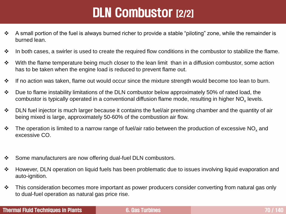
A small portion of the fuel is always burned richer to provide a stable “piloting” zone, while the remainder is
burned lean.
In both cases, a swirler is used to create the required flow conditions in the combustor to stabilize the flame.
With the flame temperature being much closer to the lean limit than in a diffusion combustor, some action
has to be taken when the engine load is reduced to prevent flame out.
If no action was taken, flame out would occur since the mixture strength would become too lean to burn.
Due to flame instability limitations of the DLN combustor below approximately 50% of rated load, the
combustor is typically operated in a conventional diffusion flame mode, resulting in higher NOx levels.
DLN fuel injector is much larger because it contains the fuel/air premixing chamber and the quantity of air
being mixed is large, approximately 50-60% of the combustion air flow.
The operation is limited to a narrow range of fuel/air ratio between the production of excessive NOx and
excessive CO.
Some manufacturers are now offering dual-fuel DLN combustors.
However, DLN operation on liquid fuels has been problematic due to issues involving liquid evaporation and
auto-ignition.
This consideration becomes more important as power producers consider converting from natural gas only
to dual-fuel operation as natural gas price rise.
DLN Combustor [2/2]
6. Gas Turbines 71 / 140Thermal Fluid Techniques in Plants
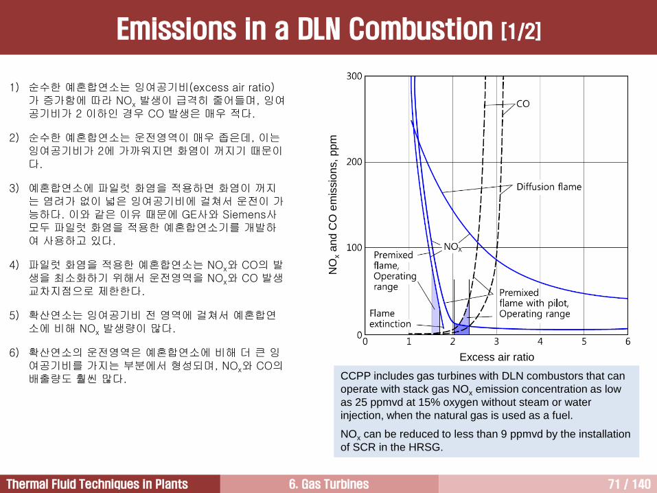
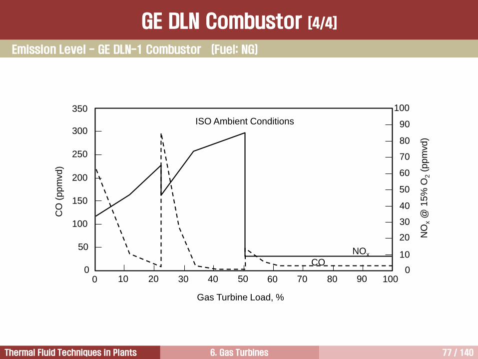
1) 순수한 예혼합연소는 잉여공기비(excess air ratio)가 증가함에 따라 NOx 발생이 급격히 줄어들며, 잉여공기비가 2 이하인 경우 CO 발생은 매우 적다.
2) 순수한 예혼합연소는 운전영역이 매우 좁은데, 이는잉여공기비가 2에 가까워지면 화염이 꺼지기 때문이다.
3) 예혼합연소에 파일럿 화염을 적용하면 화염이 꺼지는 염려가 없이 넓은 잉여공기비에 걸쳐서 운전이 가능하다. 이와 같은 이유 때문에 GE사와 Siemens사모두 파일럿 화염을 적용한 예혼합연소기를 개발하여 사용하고 있다.
4) 파일럿 화염을 적용한 예혼합연소는 NOx와 CO의 발생을 최소화하기 위해서 운전영역을 NOx와 CO 발생교차지점으로 제한한다.
5) 확산연소는 잉여공기비 전 영역에 걸쳐서 예혼합연소에 비해 NOx 발생량이 많다.
6) 확산연소의 운전영역은 예혼합연소에 비해 더 큰 잉여공기비를 가지는 부분에서 형성되며, NOx와 CO의배출량도 훨씬 많다.
Emissions in a DLN Combustion [1/2]
CCPP includes gas turbines with DLN combustors that can
operate with stack gas NOx emission concentration as low
as 25 ppmvd at 15% oxygen without steam or water
injection, when the natural gas is used as a fuel.
NOx can be reduced to less than 9 ppmvd by the installation
of SCR in the HRSG.
Excess air ratio
NO
xa
nd
CO
em
issio
ns, p
pm
6. Gas Turbines 72 / 140Thermal Fluid Techniques in Plants
Fla
me
te
mp
era
ture
Fuel to air ratio
Fuel richFuel lean
Diffusion combustor
Premixed
combustor
Extinction
of lean
premix
flame
200
250
100
150
50
0
25
Diffusion
combustorDLN
combustor
Catalytic
combustor
NO
xe
mis
sio
n, p
pm
vd
Fuel: natural gas
Emissions in a DLN Combustion [2/2]
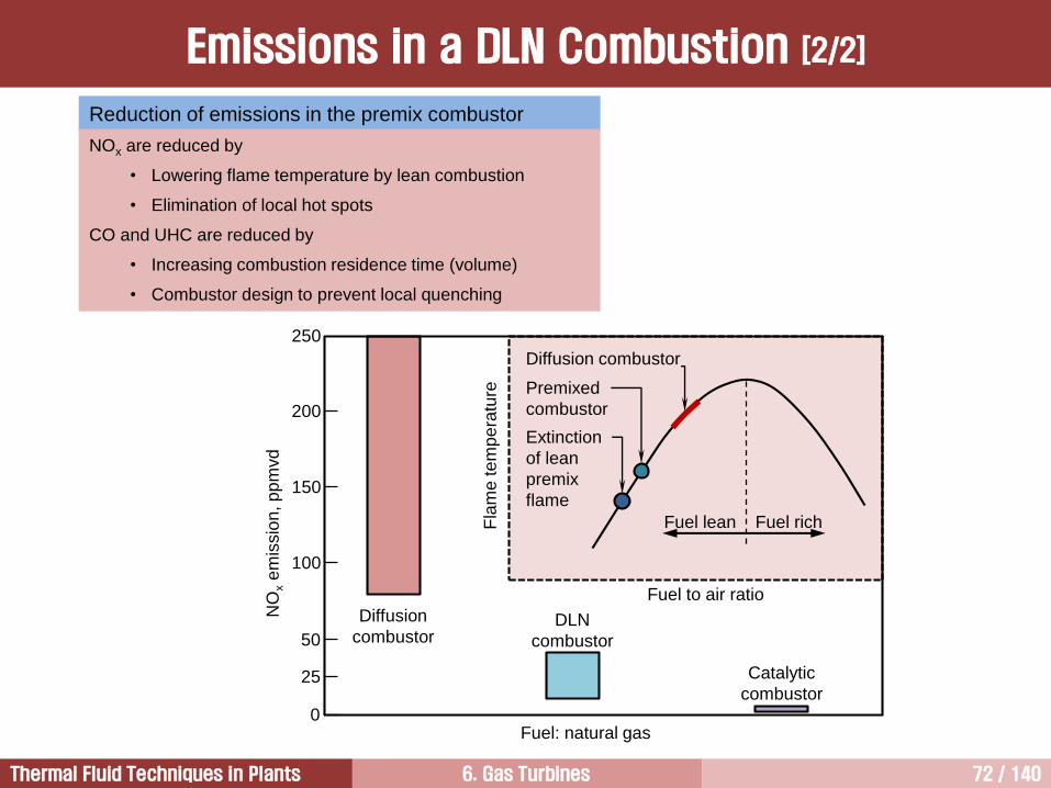
Reduction of emissions in the premix combustor
NOx are reduced by
• Lowering flame temperature by lean combustion
• Elimination of local hot spots
CO and UHC are reduced by
• Increasing combustion residence time (volume)
• Combustor design to prevent local quenching
6. Gas Turbines 73 / 140Thermal Fluid Techniques in Plants
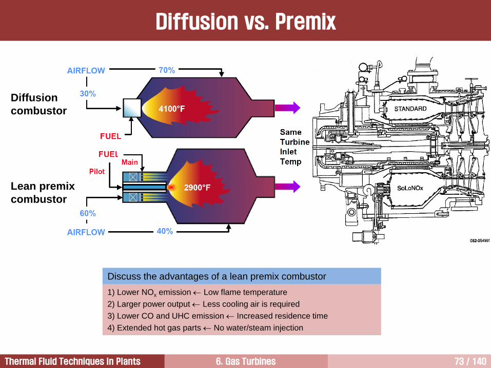
Diffusion vs. Premix
Discuss the advantages of a lean premix combustor
1) Lower NOx emission Low flame temperature
2) Larger power output Less cooling air is required
3) Lower CO and UHC emission Increased residence time
4) Extended hot gas parts No water/steam injection
Diffusion
combustor
Lean premix
combustor
6. Gas Turbines 74 / 140Thermal Fluid Techniques in Plants
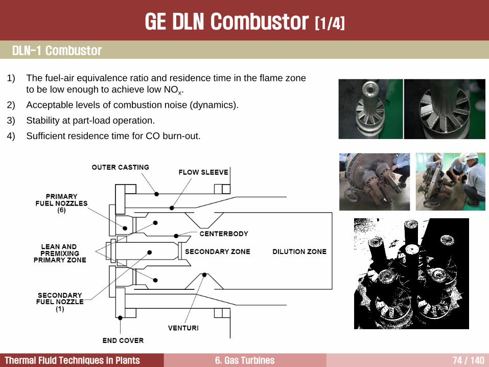
1) The fuel-air equivalence ratio and residence time in the flame zone
to be low enough to achieve low NOx.
2) Acceptable levels of combustion noise (dynamics).
3) Stability at part-load operation.
4) Sufficient residence time for CO burn-out.
GE DLN Combustor [1/4]
DLN-1 Combustor
6. Gas Turbines 75 / 140Thermal Fluid Techniques in Plants
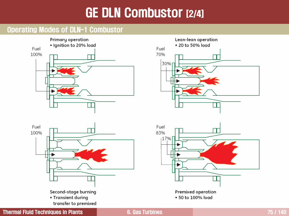
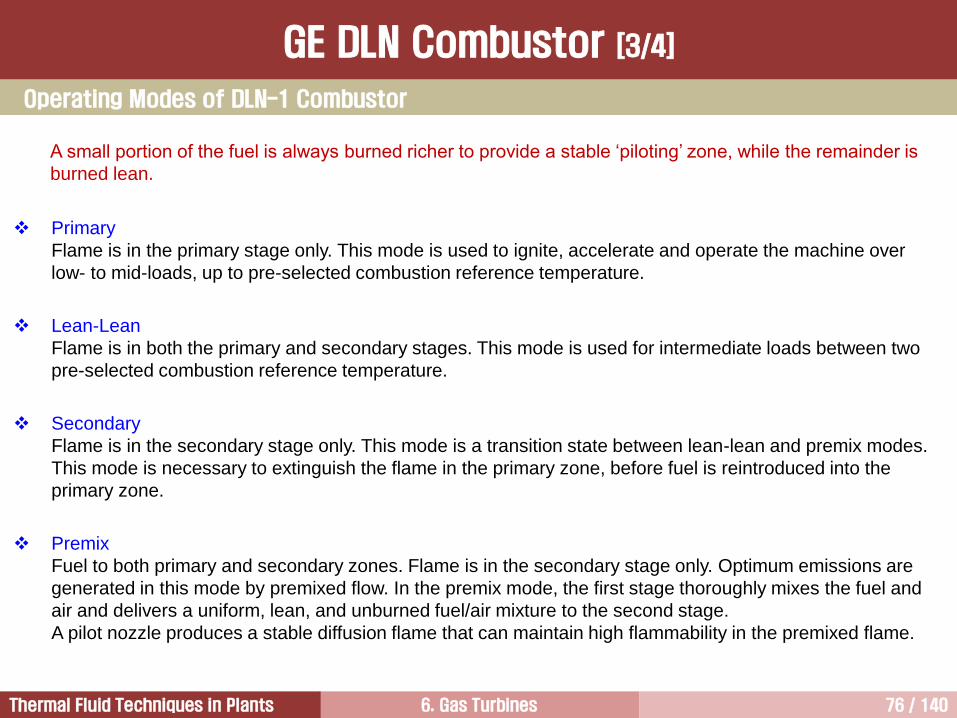
Operating Modes of DLN-1 Combustor
GE DLN Combustor [2/4]
6. Gas Turbines 76 / 140Thermal Fluid Techniques in Plants
A small portion of the fuel is always burned richer to provide a stable ‘piloting’ zone, while the remainder is
burned lean.
Primary
Flame is in the primary stage only. This mode is used to ignite, accelerate and operate the machine over
low- to mid-loads, up to pre-selected combustion reference temperature.
Lean-Lean
Flame is in both the primary and secondary stages. This mode is used for intermediate loads between two
pre-selected combustion reference temperature.
Secondary
Flame is in the secondary stage only. This mode is a transition state between lean-lean and premix modes.
This mode is necessary to extinguish the flame in the primary zone, before fuel is reintroduced into the
primary zone.
Premix
Fuel to both primary and secondary zones. Flame is in the secondary stage only. Optimum emissions are
generated in this mode by premixed flow. In the premix mode, the first stage thoroughly mixes the fuel and
air and delivers a uniform, lean, and unburned fuel/air mixture to the second stage.
A pilot nozzle produces a stable diffusion flame that can maintain high flammability in the premixed flame.
Operating Modes of DLN-1 Combustor
GE DLN Combustor [3/4]
6. Gas Turbines 77 / 140Thermal Fluid Techniques in Plants
CO
(p
pm
vd
)
350
300
250
200
150
100
50
00 10 20 30 40 50 60 70 80 90 100
0
10
20
30
40
50
60
70
80
90
100
ISO Ambient Conditions
Gas Turbine Load, %
NO
x@
15
% O
2(p
pm
vd
)
NOx
CO
Emission Level - GE DLN-1 Combustor (Fuel: NG)
GE DLN Combustor [4/4]

6. Gas Turbines 78 / 140Thermal Fluid Techniques in Plants
Compressor2
Fundamentals of Gas Turbines1
Turbine4
Combustor3
6. Gas Turbines 79 / 140Thermal Fluid Techniques in Plants
Air Inlet Compressor Combustors
Turbine
Exhaust
Cold Section Hot Section
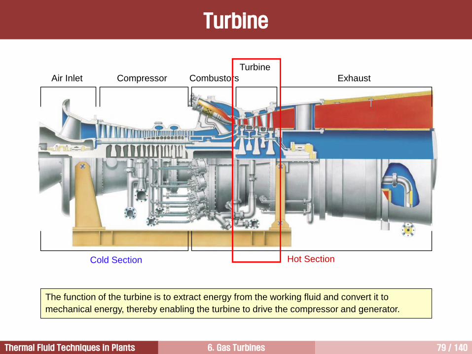
Turbine
The function of the turbine is to extract energy from the working fluid and convert it to
mechanical energy, thereby enabling the turbine to drive the compressor and generator.
6. Gas Turbines 80 / 140Thermal Fluid Techniques in Plants
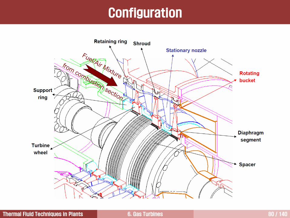
Configuration
6. Gas Turbines 81 / 140Thermal Fluid Techniques in Plants
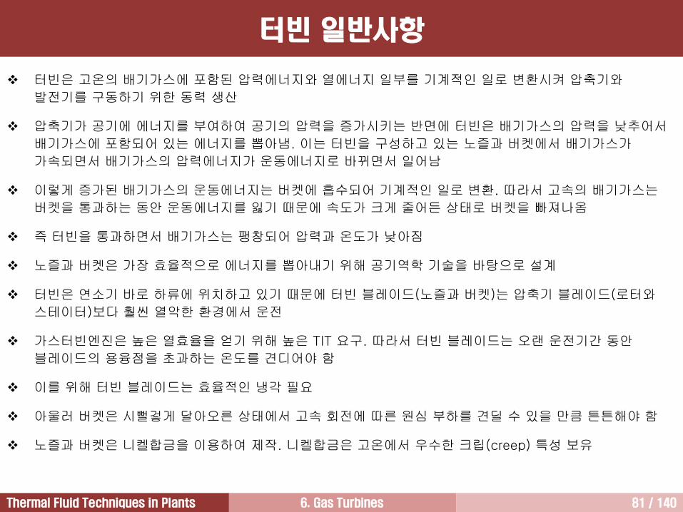
터빈 일반사항
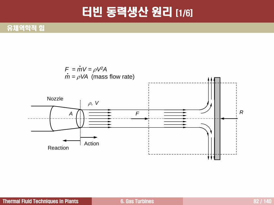
터빈은 고온의 배기가스에 포함된 압력에너지와 열에너지 일부를 기계적인 일로 변환시켜 압축기와
발전기를 구동하기 위한 동력 생산
압축기가 공기에 에너지를 부여하여 공기의 압력을 증가시키는 반면에 터빈은 배기가스의 압력을 낮추어서
배기가스에 포함되어 있는 에너지를 뽑아냄. 이는 터빈을 구성하고 있는 노즐과 버켓에서 배기가스가
가속되면서 배기가스의 압력에너지가 운동에너지로 바뀌면서 일어남
이렇게 증가된 배기가스의 운동에너지는 버켓에 흡수되어 기계적인 일로 변환. 따라서 고속의 배기가스는
버켓을 통과하는 동안 운동에너지를 잃기 때문에 속도가 크게 줄어든 상태로 버켓을 빠져나옴
즉 터빈을 통과하면서 배기가스는 팽창되어 압력과 온도가 낮아짐
노즐과 버켓은 가장 효율적으로 에너지를 뽑아내기 위해 공기역학 기술을 바탕으로 설계
터빈은 연소기 바로 하류에 위치하고 있기 때문에 터빈 블레이드(노즐과 버켓)는 압축기 블레이드(로터와
스테이터)보다 훨씬 열악한 환경에서 운전
가스터빈엔진은 높은 열효율을 얻기 위해 높은 TIT 요구. 따라서 터빈 블레이드는 오랜 운전기간 동안
블레이드의 용융점을 초과하는 온도를 견디어야 함
이를 위해 터빈 블레이드는 효율적인 냉각 필요
아울러 버켓은 시뻘겋게 달아오른 상태에서 고속 회전에 따른 원심 부하를 견딜 수 있을 만큼 튼튼해야 함
노즐과 버켓은 니켈합금을 이용하여 제작. 니켈합금은 고온에서 우수한 크립(creep) 특성 보유
6. Gas Turbines 82 / 140Thermal Fluid Techniques in Plants
R
ReactionAction
F
V
A
,Nozzle
F = mV = V2A
m = VA (mass flow rate)
유체역학적 힘
터빈 동력생산 원리 [1/6]
6. Gas Turbines 83 / 140Thermal Fluid Techniques in Plants
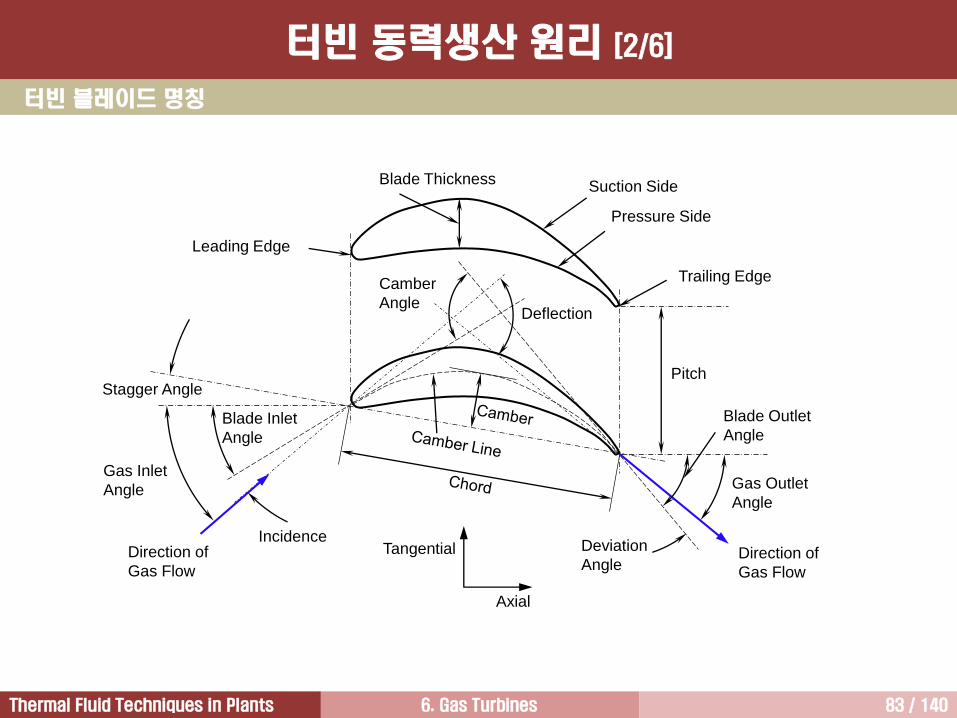
Incidence
Blade Inlet
Angle
Gas Inlet
Angle
Direction of
Gas Flow
Stagger Angle
Camber
AngleDeflection
Direction of
Gas Flow
Deviation
Angle
Gas Outlet
Angle
Blade Outlet
Angle
Pitch
Trailing Edge
Leading Edge
Blade Thickness Suction Side
Pressure Side
Axial
Tangential
터빈 블레이드 명칭
터빈 동력생산 원리 [2/6]
6. Gas Turbines 84 / 140Thermal Fluid Techniques in Plants
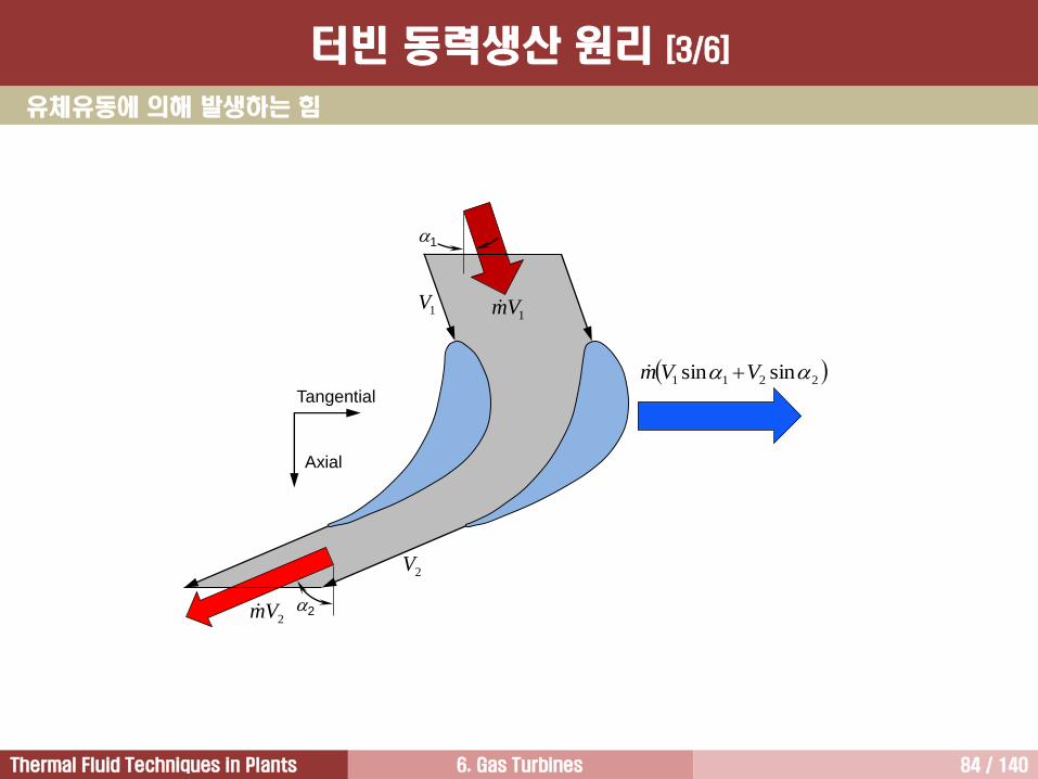
유체유동에 의해 발생하는 힘
2
1
Axial
Tangential
1Vm
2211 sinsin VVm
2Vm
1V
2V
터빈 동력생산 원리 [3/6]
6. Gas Turbines 85 / 140Thermal Fluid Techniques in Plants
유체유동에 의해 버켓에 발생하는 힘의 크기
• 배기가스는 피치에 해당하는 면적에 경사진 형태로 버켓통로로 유입
• 따라서 유동조건과 버켓 열이 형성하는 기하학적 데이터를 이용하면 유입되는 배기가스에 의해 버켓에접선방향으로 작용하는 힘의 크기 계산 가능
• 이와 같은 방법으로 버켓을 빠져나가는 유동조건을 이용하면 버켓을 빠져나가는 배기가스의 반작용에 의해 발생하는 접선방향 힘의 크기 계산
• 그리고 유입되는 배기가스와 배출되는 배기가스에 의해 접선방향으로 작용하는 두 힘의 크기를 합치면버켓에 접선방향으로 작용하는 전체 힘의 크기가 됨
• 그러나 이 방법으로는 버켓에 작용하는 힘의 크기를 정확하게 계산하기 어려움. 그 이유는 버켓 날개 표면에서 발생하는 경계층 때문에 버켓을 빠져나오는 유동이 균일하지 못하기 때문임
버켓에 작용하는 힘을 계산하기 위한 또 다른 방법으로 날개이론
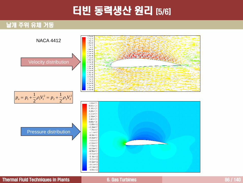
• 이 방법은 버켓 표면에 작용하는 압력분포를 이용하여 양력을 계산하는 방법으로써 가장 정확하면서 실제적으로 가장 많이 이용
• 흡입면 압력이 압력면에 비해서 낮으며, 이로 인해 버켓에 양력 발생
터빈 동력생산 원리 [4/6]
6. Gas Turbines 86 / 140Thermal Fluid Techniques in Plants
NACA 4412
2
222
2
1112
1
2
1VpVppo
Pressure distribution
Velocity distribution
날개 주위 유체 거동
터빈 동력생산 원리 [5/6]
6. Gas Turbines 87 / 140Thermal Fluid Techniques in Plants
c1
2c2
P S S P
p2 p1 p
po
½ c12
½ c22
p2
1
bDirection of
Rotation
P: Pressure Surface
S: Suction Surface
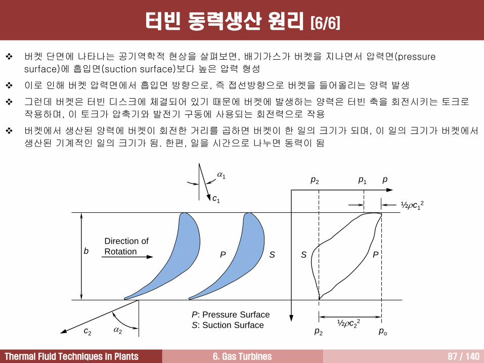
버켓 단면에 나타나는 공기역학적 현상을 살펴보면, 배기가스가 버켓을 지나면서 압력면(pressure
surface)에 흡입면(suction surface)보다 높은 압력 형성
이로 인해 버켓 압력면에서 흡입면 방향으로, 즉 접선방향으로 버켓을 들어올리는 양력 발생
그런데 버켓은 터빈 디스크에 체결되어 있기 때문에 버켓에 발생하는 양력은 터빈 축을 회전시키는 토크로
작용하며, 이 토크가 압축기와 발전기 구동에 사용되는 회전력으로 작용
버켓에서 생산된 양력에 버켓이 회전한 거리를 곱하면 버켓이 한 일의 크기가 되며, 이 일의 크기가 버켓에서
생산된 기계적인 일의 크기가 됨. 한편, 일을 시간으로 나누면 동력이 됨
터빈 동력생산 원리 [6/6]
6. Gas Turbines 88 / 140Thermal Fluid Techniques in Plants
노즐 (고정 블레이드)
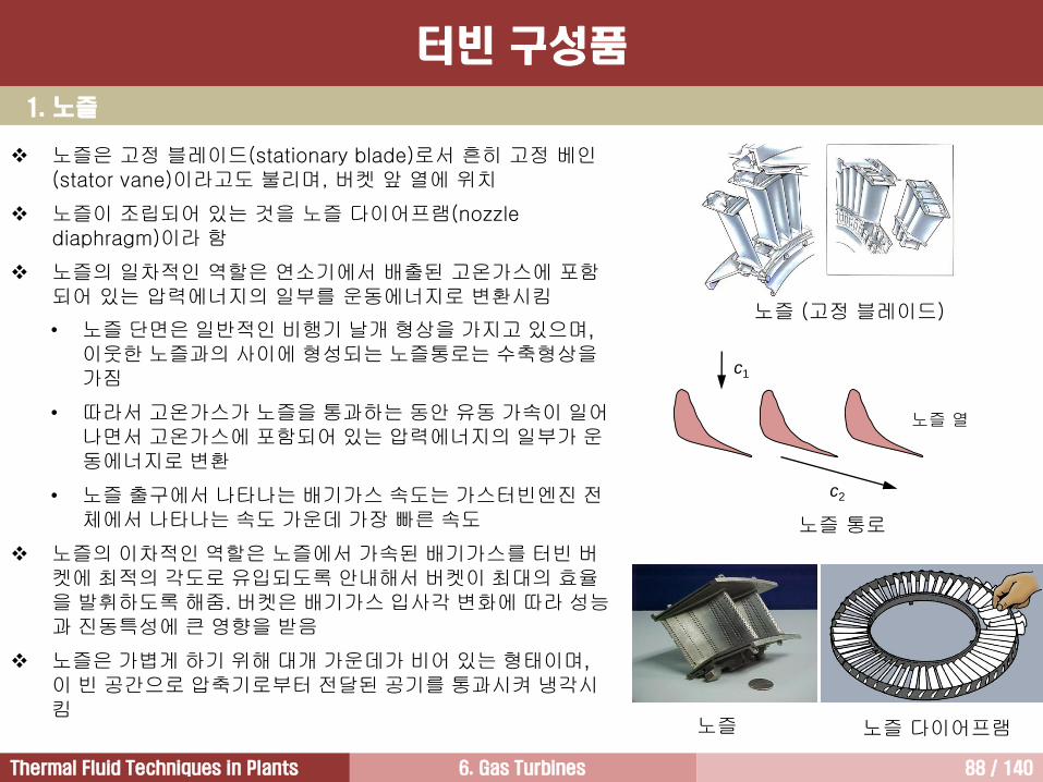
노즐은 고정 블레이드(stationary blade)로서 흔히 고정 베인(stator vane)이라고도 불리며, 버켓 앞 열에 위치
노즐이 조립되어 있는 것을 노즐 다이어프램(nozzle diaphragm)이라 함
노즐의 일차적인 역할은 연소기에서 배출된 고온가스에 포함되어 있는 압력에너지의 일부를 운동에너지로 변환시킴
• 노즐 단면은 일반적인 비행기 날개 형상을 가지고 있으며,
이웃한 노즐과의 사이에 형성되는 노즐통로는 수축형상을가짐
• 따라서 고온가스가 노즐을 통과하는 동안 유동 가속이 일어나면서 고온가스에 포함되어 있는 압력에너지의 일부가 운동에너지로 변환
• 노즐 출구에서 나타나는 배기가스 속도는 가스터빈엔진 전체에서 나타나는 속도 가운데 가장 빠른 속도
노즐의 이차적인 역할은 노즐에서 가속된 배기가스를 터빈 버켓에 최적의 각도로 유입되도록 안내해서 버켓이 최대의 효율을 발휘하도록 해줌. 버켓은 배기가스 입사각 변화에 따라 성능과 진동특성에 큰 영향을 받음
노즐은 가볍게 하기 위해 대개 가운데가 비어 있는 형태이며,
이 빈 공간으로 압축기로부터 전달된 공기를 통과시켜 냉각시킴
1. 노즐
노즐 다이어프램노즐
c2
노즐 열
c1
노즐 통로
터빈 구성품
6. Gas Turbines 89 / 140Thermal Fluid Techniques in Plants
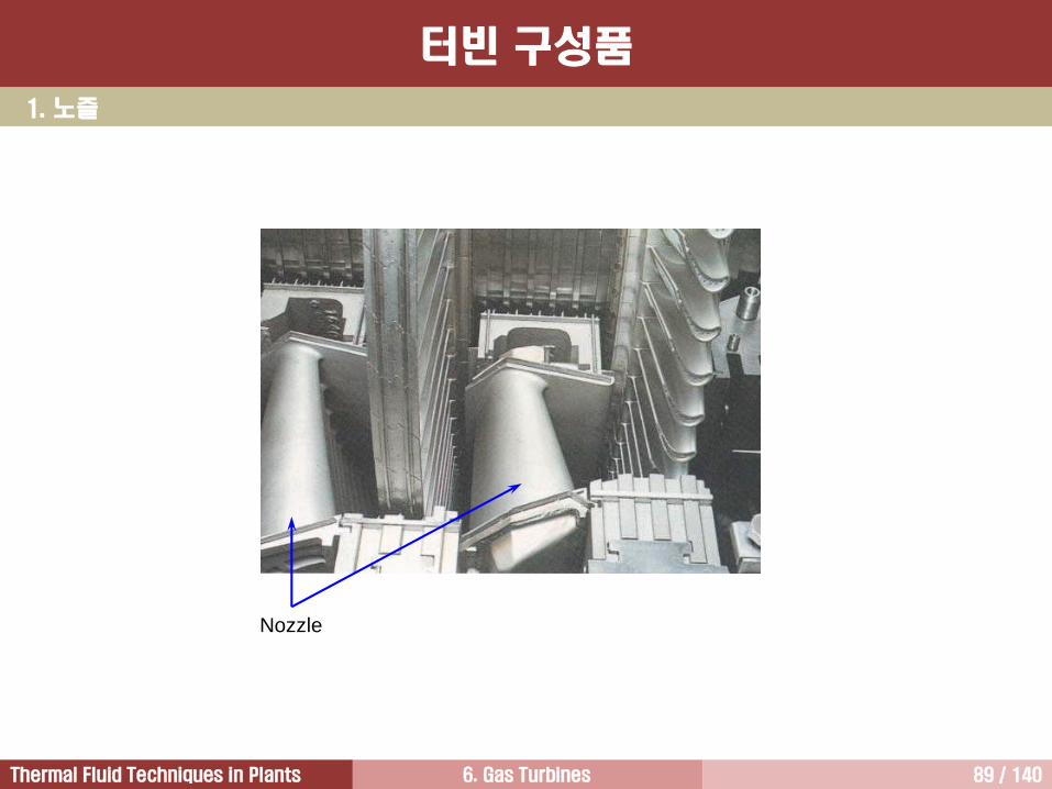
Nozzle
1. 노즐
터빈 구성품
6. Gas Turbines 90 / 140Thermal Fluid Techniques in Plants
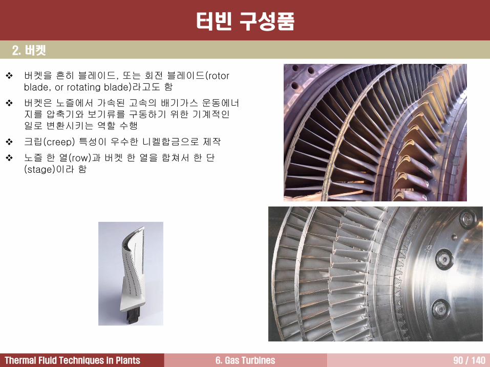
2. 버켓
버켓을 흔히 블레이드, 또는 회전 블레이드(rotor blade, or rotating blade)라고도 함
버켓은 노즐에서 가속된 고속의 배기가스 운동에너지를 압축기와 보기류를 구동하기 위한 기계적인일로 변환시키는 역할 수행
크립(creep) 특성이 우수한 니켈합금으로 제작
노즐 한 열(row)과 버켓 한 열을 합쳐서 한 단(stage)이라 함
터빈 구성품
6. Gas Turbines 91 / 140Thermal Fluid Techniques in Plants
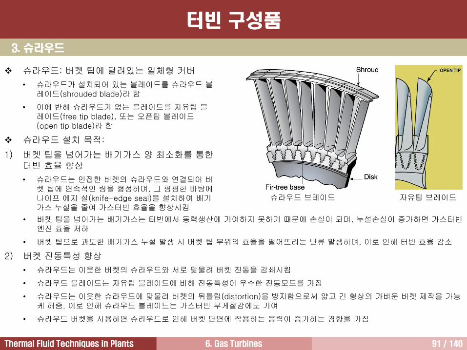
3. 슈라우드
터빈 구성품
슈라우드 브레이드
슈라우드: 버켓 팁에 달려있는 일체형 커버
• 슈라우드가 설치되어 있는 블레이드를 슈라우드 블레이드(shrouded blade)라 함
• 이에 반해 슈라우드가 없는 블레이드를 자유팁 블레이드(free tip blade), 또는 오픈팁 블레이드(open tip blade)라 함
슈라우드 설치 목적:
1) 버켓 팁을 넘어가는 배기가스 양 최소화를 통한터빈 효율 향상
• 슈라우드는 인접한 버켓의 슈라우드와 연결되어 버켓 팁에 연속적인 링을 형성하며, 그 평평한 바탕에나이프 에지 실(knife-edge seal)을 설치하여 배기가스 누설을 줄여 가스터빈 효율을 향상시킴
• 버켓 팁을 넘어가는 배기가스는 터빈에서 동력생산에 기여하지 못하기 때문에 손실이 되며, 누설손실이 증가하면 가스터빈엔진 효율 저하
• 버켓 팁으로 과도한 배기가스 누설 발생 시 버켓 팁 부위의 효율을 떨어뜨리는 난류 발생하며, 이로 인해 터빈 효율 감소
2) 버켓 진동특성 향상
• 슈라우드는 이웃한 버켓의 슈라우드와 서로 맞물려 버켓 진동을 감쇄시킴
• 슈라우드 블레이드는 자유팁 블레이드에 비해 진동특성이 우수한 진동모드를 가짐
• 슈라우드는 이웃한 슈라우드에 맞물려 버켓의 뒤틀림(distortion)을 방지함으로써 얇고 긴 형상의 가벼운 버켓 제작을 가능케 해줌. 이로 인해 슈라우드 블레이드는 가스터빈 무게절감에도 기여
• 슈라우드 버켓을 사용하면 슈라우드로 인해 버켓 단면에 작용하는 응력이 증가하는 경향을 가짐
자유팁 브레이드
6. Gas Turbines 92 / 140Thermal Fluid Techniques in Plants
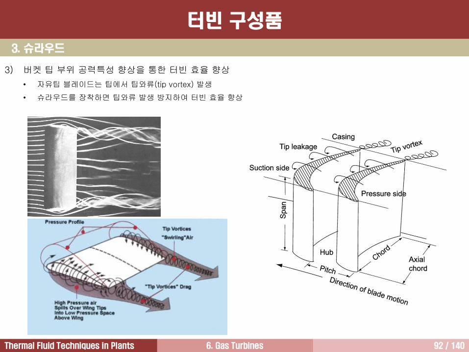
3) 버켓 팁 부위 공력특성 향상을 통한 터빈 효율 향상
• 자유팁 블레이드는 팁에서 팁와류(tip vortex) 발생
• 슈라우드를 장착하면 팁와류 발생 방지하여 터빈 효율 향상
3. 슈라우드
터빈 구성품
6. Gas Turbines 93 / 140Thermal Fluid Techniques in Plants
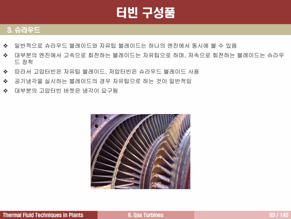
일반적으로 슈라우드 블레이드와 자유팁 블레이드는 하나의 엔진에서 동시에 볼 수 있음
대부분의 엔진에서 고속으로 회전하는 블레이드는 자유팁으로 하며, 저속으로 회전하는 블레이드는 슈라우드 장착
따라서 고압터빈은 자유팁 블레이드, 저압터빈은 슈라우드 블레이드 사용
공기냉각을 실시하는 블레이드의 경우 자유팁으로 하는 것이 일반적임
대부분의 고압터빈 버켓은 냉각이 요구됨
3. 슈라우드
터빈 구성품
6. Gas Turbines 94 / 140Thermal Fluid Techniques in Plants
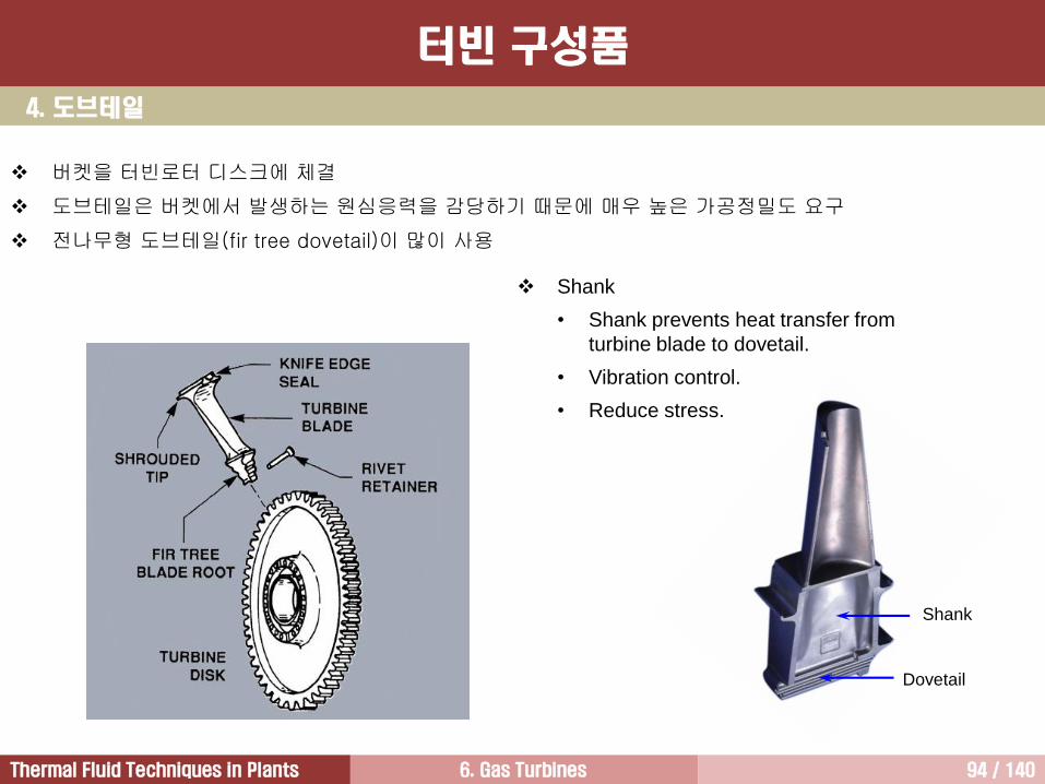
4. 도브테일
버켓을 터빈로터 디스크에 체결
도브테일은 버켓에서 발생하는 원심응력을 감당하기 때문에 매우 높은 가공정밀도 요구
전나무형 도브테일(fir tree dovetail)이 많이 사용
터빈 구성품
Dovetail
Shank
Shank
• Shank prevents heat transfer from
turbine blade to dovetail.
• Vibration control.
• Reduce stress.
6. Gas Turbines 95 / 140Thermal Fluid Techniques in Plants
Compressor
Fuel Combustor
Turbine
Air
Power
Exhaust gas1
243
4,3, ooT hhTW
4,3, oopT TTc
1
3,
4,
3,
3,
4,
3, 11o
o
opT
o
o
opTp
pTc
T
TTc
1
3, 1 TPRTc opT
1
3,
4,
3,
4,
o
o
o
o
T
T
p
pTPR
T
p
o
o
o
c
h
T
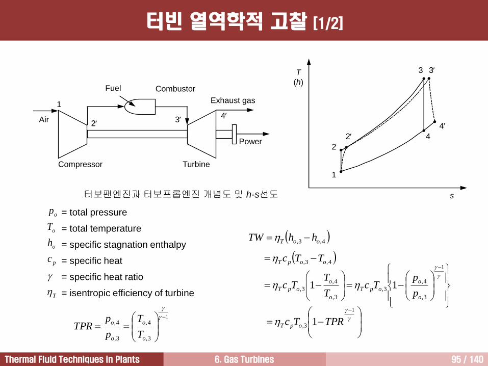
p
= total pressure
= total temperature
= specific stagnation enthalpy
= specific heat
= specific heat ratio
= isentropic efficiency of turbine
터보팬엔진과 터보프롭엔진 개념도 및 h-s선도
T
(h)
s
1
2
3
4
3
4
2
터빈 열역학적 고찰 [1/2]
6. Gas Turbines 96 / 140Thermal Fluid Techniques in Plants
터빈에서 일어나는 과정을 열역학적으로 살펴보면, 즉 터빈에서 일어나는 손실을 무시하거나 손실의 크기가
매우 작다고 가정하면, 터빈에서는 등엔트로피팽창과정(그림에서 과정 34)을 통해 동력이 생산됨.
그러나 실제적으로 터빈에서는 손실이 발생하며, 발생하는 손실을 반영하면 터빈에서는 단열팽창과정이
일어남(그림에서 과정 34)
즉 터빈에서 과정이 진행되는 동안 터빈 내부로 열이 공급되지도 않으며, 터빈 내부로부터 외부로 열이
빠져나가지도 않음. 그러나 엄밀하게 살펴보면, 터빈 케이싱이 가열되면서 일부 열이 터빈 케이싱을 통해
터빈 외부로 빠져나가기 때문에 단열과정 아님. 그러나 터빈을 통과하는 배기가스 속도가 너무 빨라서 미처
열교환이 일어날 시간이 없다고 가정하면 터빈에서 단열과정이 일어남
배기가스가 터빈을 통과하는 동안 전체압력과 전체온도가 낮아지는 팽창과정이 진행되며, 이 팽창과정을
위해 압축기에서 공기의 압력을 올리는 것임
열역학 제1법칙을 이용하여 터빈에서 생산되는 열역학적인 일의 크기를 계산하면 (ho,3-ho,4)임. 여기서 ho는
정체엔탈피(stagnation enthalpy). 엔탈피는 내부에너지와 유동에너지를 합친 값으로 정의
그러나 터빈에서 발생하는 다양한 손실, 즉 형상손실, 이차유동손실, 누설손실 등으로 인해 실질적으로
터빈에서 생산되는 일의 크기는 이상적인 일의 크기보다 작아짐
터빈에서 실질적으로 생산되는 일의 크기는 열역학적 일의 크기에 터빈효율을 곱한 값
터빈에서 일어나는 배기가스 압력강하는 터빈압력비(TPR; Turbine Pressure Ratio)로 나타냄. 터빈압력비는
터빈 출구압력(po,4)을 터빈 입구압력 (po,3)으로 나눈 값으로 정의
결과적으로 터빈에서 생산되는 일의 크기에 관한 관계식을 살펴보면, 터빈에서 생산되는 일의 크기는
터빈압력비, TIT, 정압비열 및 비열비와 같은 공기의 상태량, 그리고 터빈효율에 영향을 받음
터빈 열역학적 고찰 [2/2]
6. Gas Turbines 97 / 140Thermal Fluid Techniques in Plants
노즐 열 버켓 열
z
r
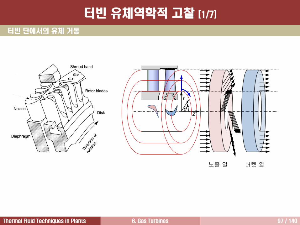
터빈 단에서의 유체 거동
터빈 유체역학적 고찰 [1/7]
6. Gas Turbines 98 / 140Thermal Fluid Techniques in Plants
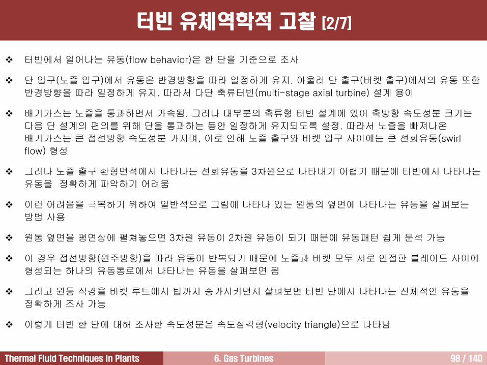
터빈에서 일어나는 유동(flow behavior)은 한 단을 기준으로 조사
단 입구(노즐 입구)에서 유동은 반경방향을 따라 일정하게 유지. 아울러 단 출구(버켓 출구)에서의 유동 또한
반경방향을 따라 일정하게 유지. 따라서 다단 축류터빈(multi-stage axial turbine) 설계 용이
배기가스는 노즐을 통과하면서 가속됨. 그러나 대부분의 축류형 터빈 설계에 있어 축방향 속도성분 크기는
다음 단 설계의 편의를 위해 단을 통과하는 동안 일정하게 유지되도록 설정. 따라서 노즐을 빠져나온
배기가스는 큰 접선방향 속도성분 가지며, 이로 인해 노즐 출구와 버켓 입구 사이에는 큰 선회유동(swirl
flow) 형성
그러나 노즐 출구 환형면적에서 나타나는 선회유동을 3차원으로 나타내기 어렵기 때문에 터빈에서 나타나는
유동을 정확하게 파악하기 어려움
이런 어려움을 극복하기 위하여 일반적으로 그림에 나타나 있는 원통의 옆면에 나타나는 유동을 살펴보는
방법 사용
원통 옆면을 평면상에 펼쳐놓으면 3차원 유동이 2차원 유동이 되기 때문에 유동패턴 쉽게 분석 가능
이 경우 접선방향(원주방향)을 따라 유동이 반복되기 때문에 노즐과 버켓 모두 서로 인접한 블레이드 사이에
형성되는 하나의 유동통로에서 나타나는 유동을 살펴보면 됨
그리고 원통 직경을 버켓 루트에서 팁까지 증가시키면서 살펴보면 터빈 단에서 나타나는 전체적인 유동을
정확하게 조사 가능
이렇게 터빈 한 단에 대해 조사한 속도성분은 속도삼각형(velocity triangle)으로 나타남
터빈 유체역학적 고찰 [2/7]
6. Gas Turbines 99 / 140Thermal Fluid Techniques in Plants
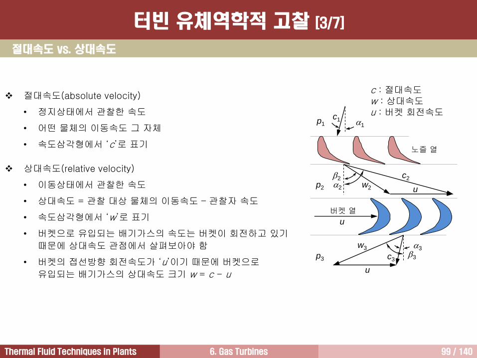
c : 절대속도w : 상대속도u : 버켓 회전속도
u
u
c2
w2
2
2
w3
3c3
p1
p2
p3
u
1
c1
3
노즐 열
버켓 열
절대속도 vs. 상대속도
절대속도(absolute velocity)
• 정지상태에서 관찰한 속도
• 어떤 물체의 이동속도 그 자체
• 속도삼각형에서 ‘c’로 표기
상대속도(relative velocity)
• 이동상태에서 관찰한 속도
• 상대속도 = 관찰 대상 물체의 이동속도 – 관찰자 속도
• 속도삼각형에서 ‘w’로 표기
• 버켓으로 유입되는 배기가스의 속도는 버켓이 회전하고 있기
때문에 상대속도 관점에서 살펴보아야 함
• 버켓의 접선방향 회전속도가 ‘u’이기 때문에 버켓으로
유입되는 배기가스의 상대속도 크기 w = c - u
터빈 유체역학적 고찰 [3/7]
6. Gas Turbines 100 / 140Thermal Fluid Techniques in Plants
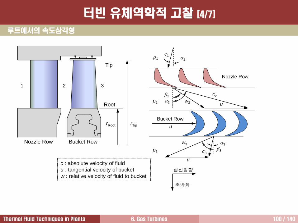
루트에서의 속도삼각형
c : absolute velocity of fluid
u : tangential velocity of bucket
w : relative velocity of fluid to bucket
u
u
c2
w2
2
2
w3
3c3
p1
p2
p3
u
1
c1
3
Nozzle Row
Bucket Row
접선방향
축방향
Root
Tip
rRoot rTip
Nozzle Row Bucket Row
1 2 3
터빈 유체역학적 고찰 [4/7]
6. Gas Turbines 101 / 140Thermal Fluid Techniques in Plants
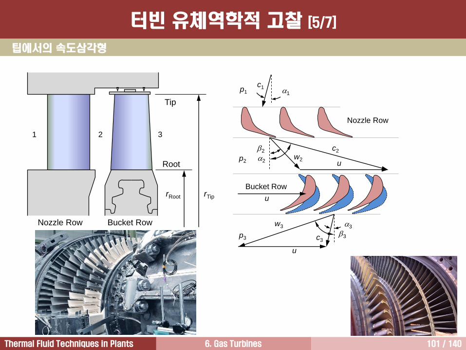
팁에서의 속도삼각형
u
u
c2
w2
w3
p1
p2
p3
u
1
c1
Nozzle Row
Bucket Row
2
2
3c3
3
Root
Tip
rRoot rTip
Nozzle Row Bucket Row
1 2 3
터빈 유체역학적 고찰 [5/7]
6. Gas Turbines 102 / 140Thermal Fluid Techniques in Plants
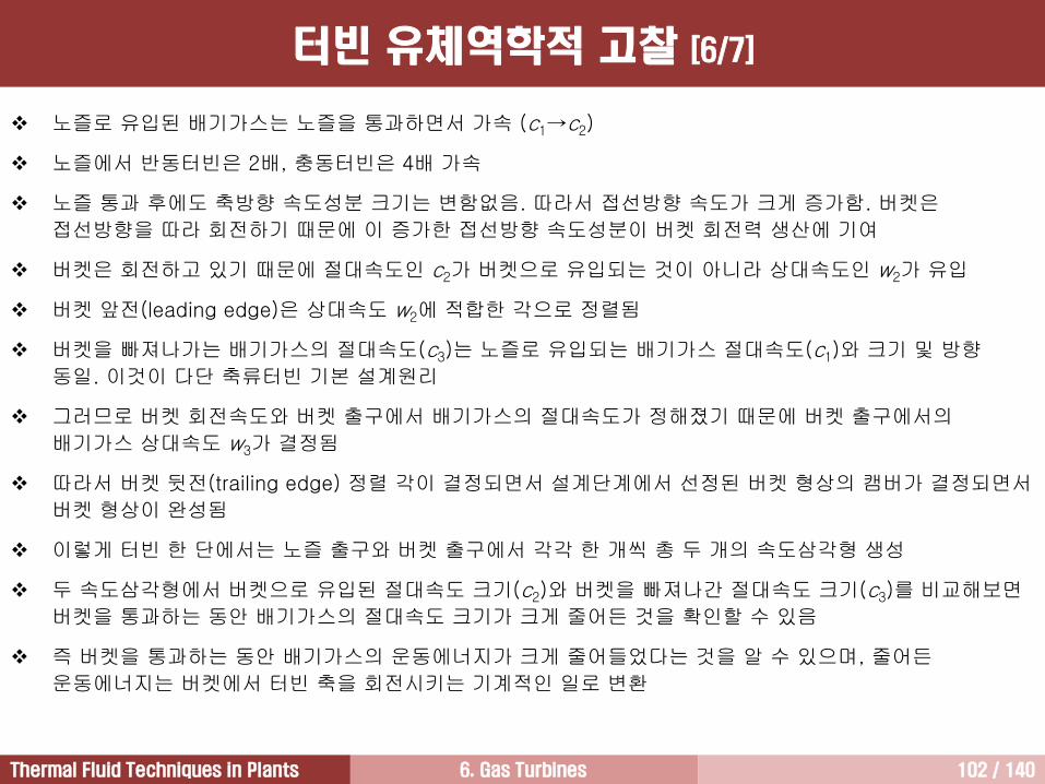
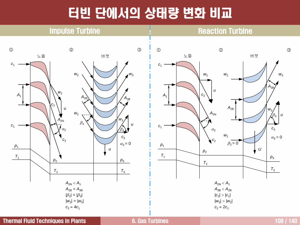
노즐로 유입된 배기가스는 노즐을 통과하면서 가속 (c1→c2)
노즐에서 반동터빈은 2배, 충동터빈은 4배 가속
노즐 통과 후에도 축방향 속도성분 크기는 변함없음. 따라서 접선방향 속도가 크게 증가함. 버켓은
접선방향을 따라 회전하기 때문에 이 증가한 접선방향 속도성분이 버켓 회전력 생산에 기여
버켓은 회전하고 있기 때문에 절대속도인 c2가 버켓으로 유입되는 것이 아니라 상대속도인 w2가 유입
버켓 앞전(leading edge)은 상대속도 w2에 적합한 각으로 정렬됨
버켓을 빠져나가는 배기가스의 절대속도(c3)는 노즐로 유입되는 배기가스 절대속도(c1)와 크기 및 방향
동일. 이것이 다단 축류터빈 기본 설계원리
그러므로 버켓 회전속도와 버켓 출구에서 배기가스의 절대속도가 정해졌기 때문에 버켓 출구에서의
배기가스 상대속도 w3가 결정됨
따라서 버켓 뒷전(trailing edge) 정렬 각이 결정되면서 설계단계에서 선정된 버켓 형상의 캠버가 결정되면서
버켓 형상이 완성됨
이렇게 터빈 한 단에서는 노즐 출구와 버켓 출구에서 각각 한 개씩 총 두 개의 속도삼각형 생성
두 속도삼각형에서 버켓으로 유입된 절대속도 크기(c2)와 버켓을 빠져나간 절대속도 크기(c3)를 비교해보면
버켓을 통과하는 동안 배기가스의 절대속도 크기가 크게 줄어든 것을 확인할 수 있음
즉 버켓을 통과하는 동안 배기가스의 운동에너지가 크게 줄어들었다는 것을 알 수 있으며, 줄어든
운동에너지는 버켓에서 터빈 축을 회전시키는 기계적인 일로 변환
터빈 유체역학적 고찰 [6/7]
6. Gas Turbines 103 / 140Thermal Fluid Techniques in Plants
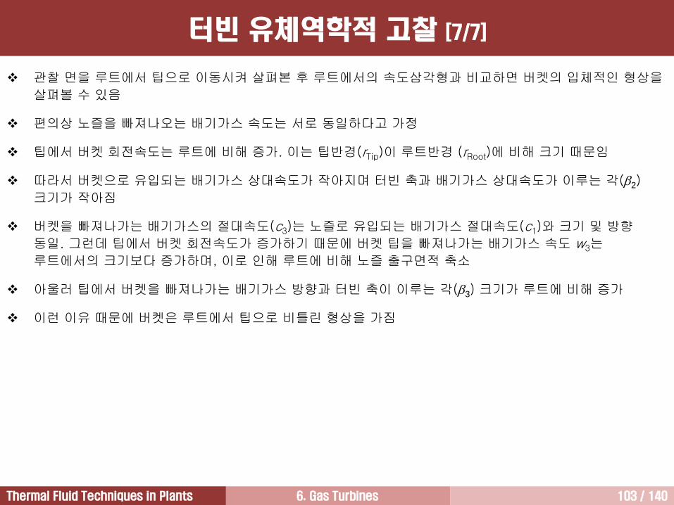
관찰 면을 루트에서 팁으로 이동시켜 살펴본 후 루트에서의 속도삼각형과 비교하면 버켓의 입체적인 형상을
살펴볼 수 있음
편의상 노즐을 빠져나오는 배기가스 속도는 서로 동일하다고 가정
팁에서 버켓 회전속도는 루트에 비해 증가. 이는 팁반경(rTip)이 루트반경 (rRoot)에 비해 크기 때문임
따라서 버켓으로 유입되는 배기가스 상대속도가 작아지며 터빈 축과 배기가스 상대속도가 이루는 각(2)
크기가 작아짐
버켓을 빠져나가는 배기가스의 절대속도(c3)는 노즐로 유입되는 배기가스 절대속도(c1)와 크기 및 방향
동일. 그런데 팁에서 버켓 회전속도가 증가하기 때문에 버켓 팁을 빠져나가는 배기가스 속도 w3는
루트에서의 크기보다 증가하며, 이로 인해 루트에 비해 노즐 출구면적 축소
아울러 팁에서 버켓을 빠져나가는 배기가스 방향과 터빈 축이 이루는 각(3) 크기가 루트에 비해 증가
이런 이유 때문에 버켓은 루트에서 팁으로 비틀린 형상을 가짐
터빈 유체역학적 고찰 [7/7]
6. Gas Turbines 104 / 140Thermal Fluid Techniques in Plants
반동도
%10031
32
hh
hh
%10031
32
TT
TT
%10031
32
pp
pp
dpdhq
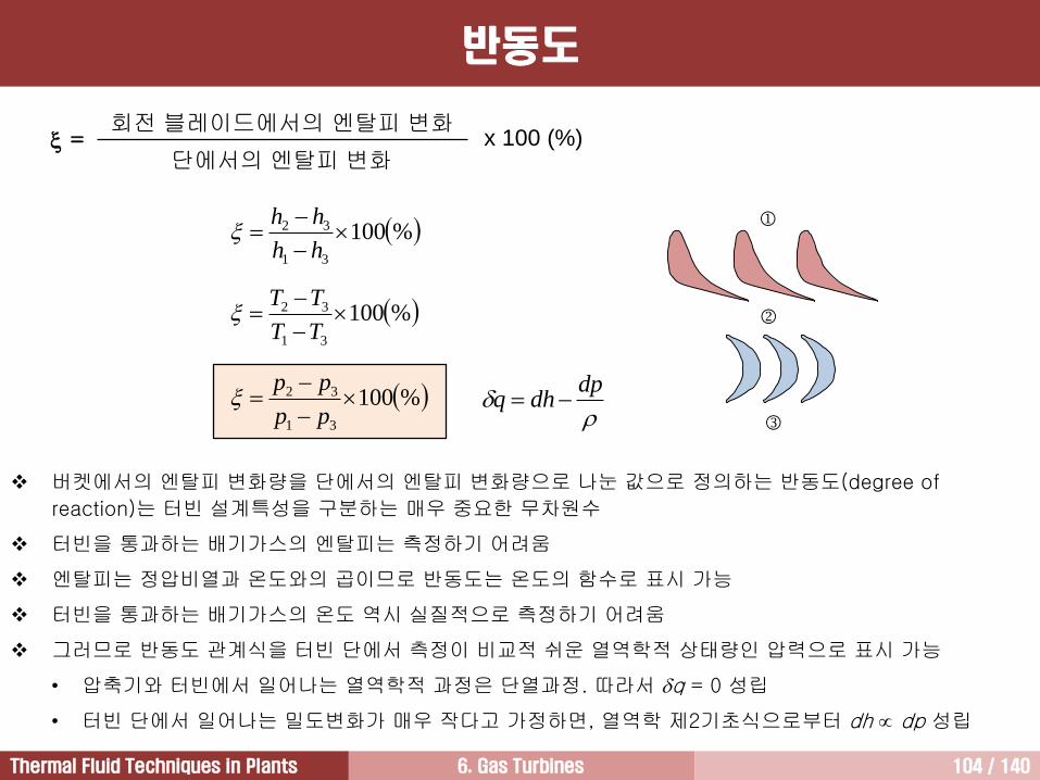
회전 블레이드에서의 엔탈피 변화
단에서의 엔탈피 변화 = x 100 (%)
버켓에서의 엔탈피 변화량을 단에서의 엔탈피 변화량으로 나눈 값으로 정의하는 반동도(degree of
reaction)는 터빈 설계특성을 구분하는 매우 중요한 무차원수
터빈을 통과하는 배기가스의 엔탈피는 측정하기 어려움
엔탈피는 정압비열과 온도와의 곱이므로 반동도는 온도의 함수로 표시 가능
터빈을 통과하는 배기가스의 온도 역시 실질적으로 측정하기 어려움
그러므로 반동도 관계식을 터빈 단에서 측정이 비교적 쉬운 열역학적 상태량인 압력으로 표시 가능
• 압축기와 터빈에서 일어나는 열역학적 과정은 단열과정. 따라서 q = 0 성립
• 터빈 단에서 일어나는 밀도변화가 매우 작다고 가정하면, 열역학 제2기초식으로부터 dh dp 성립

6. Gas Turbines 105 / 140Thermal Fluid Techniques in Plants
충동터빈(impulse turbine): 반동도 0%를 가지는 터빈 단으로
구성된 터빈
터빈 단에서 압력강하는 노즐에서만 일어남
버켓에서는 압력강하가 일어나지 않기 때문에 버켓을 통과하는
동안 배기가스 속도는 일정하게 유지. 그러므로 버켓통로
단면적은 버켓 입구로부터 출구에 이르기까지 일정. 이런 조건을
만족시키기 위해 충동터빈 버켓 단면은 초승달 형상임
충동터빈은 고속 배기가스의 운동방향을 바꾸어서 에너지 흡수
노즐 열
버켓 열
[ 충동터빈, = 0% ]
Vj U
Vj U버켓
F
U
충동터빈
6. Gas Turbines 106 / 140Thermal Fluid Techniques in Plants
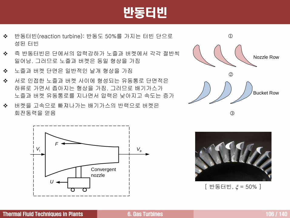
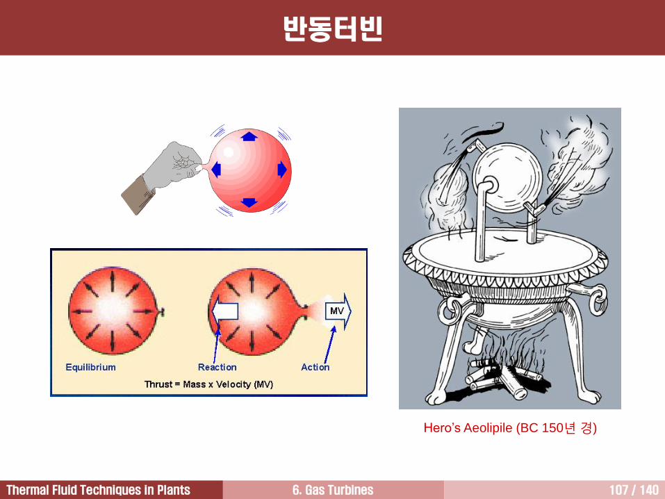
반동터빈(reaction turbine): 반동도 50%를 가지는 터빈 단으로
성된 터빈
즉 반동터빈은 단에서의 압력강하가 노즐과 버켓에서 각각 절반씩
일어남. 그러므로 노즐과 버켓은 동일 형상을 가짐
노즐과 버켓 단면은 일반적인 날개 형상을 가짐
서로 인접한 노즐과 버켓 사이에 형성되는 유동통로 단면적은
하류로 가면서 좁아지는 형상을 가짐. 그러므로 배기가스가
노즐과 버켓 유동통로를 지나면서 압력은 낮아지고 속도는 증가
버켓을 고속으로 빠져나가는 배기가스의 반력으로 버켓은
회전동력을 얻음
Nozzle Row
Bucket Row
[ 반동터빈, = 50% ]
Vi
Convergent
nozzle
Ve
U
F
반동터빈
6. Gas Turbines 107 / 140Thermal Fluid Techniques in Plants
Hero’s Aeolipile (BC 150년경)
반동터빈
6. Gas Turbines 108 / 140Thermal Fluid Techniques in Plants
c1
u
2
c2
p1
p2
u
w2
w2
노즐 버켓
A1
A2N2
A2B A3B
w3
u
c3
3 = 0
A2N A1
A2B = A3B
|2| = |3|
|w2| = |w3|
c2 4c1
p3
T1
T2 T3
c2
c1
w2
w3
3
c1
U
2
c2
p1
p2
u
w2 w2
노즐 버켓
A1
A2N 3
w3
c3
3 = 0
p3T1
T2
T3
c2
A2B
A3B
u
w3
2 = 0
A2N A1
A3B A2B
|c2| |c1|
|w3| |w2|
c2 2c1
c1
w2
Impulse Turbine Reaction Turbine
터빈 단에서의 상태량 변화 비교
6. Gas Turbines 109 / 140Thermal Fluid Techniques in Plants
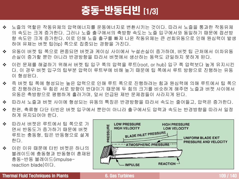
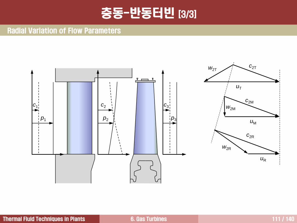
노즐의 역할은 작동유체의 압력에너지를 운동에너지로 변환시키는 것이다. 따라서 노즐을 통과한 작동유체의 속도는 크게 증가한다. 그러나 노즐 출구에서의 축방향 속도는 노즐 입구에서와 동일하기 때문에 접선방향 속도만 크게 증가한다. 이로 인해 노즐 출구를 빠져 나온 작동유체는 큰 선회유동으로 인해 원심력이 발생하여 유체는 버켓 팁(tip) 쪽으로 집중되는 경향을 가진다.
유동이 버켓 팁 쪽으로 편중되면 버켓과 케이싱 사이에서 누설손실이 증가하며, 버켓 팁 근처에서 이차유동손실이 증가할 뿐만 아니라 반경방향을 따라서 버켓에서 생산하는 동력도 균일하지 못하게 된다.
이런 문제를 해결하기 위해서 버켓 팁 입구 쪽의 압력을 루트(root, or hub) 입구 쪽 압력보다 높게 유지시킨다. 이 경우 버켓 입구의 팁부분 압력이 루트부에 비해 높기 때문에 팁 쪽에서 루트 방향으로 진행하는 유동이 형성된다.
즉 버켓 팁 쪽에 형성되는 높은 압력으로 인해 루트 쪽으로 진행하려는 힘과 원심력에 의해 루트에서 팁 쪽으로 진행하려는 두 힘은 서로 방향이 반대이기 때문에 두 힘의 크기를 비슷하게 해주면 노즐과 버켓 사이에서유동은 축방향으로 평행하게 흘러가며, 앞서 언급된 제반 문제점들이 사라지게 된다.
따라서 노즐과 버켓 사이에 형성되는 유동의 특징은 반경방향을 따라서 속도는 줄어들고, 압력은 증가한다.
한편, 축류형 다단 터빈은 버켓 입구에서 뿐만이 아니라 출구에서도 압력과 속도는 반경방향을 따라서 일정하게 유지되어야 한다.
따라서 버켓은 루트에서 팁 쪽으로 가면서 반동도가 증가하기 때문에 버켓루트는 충동형, 팁은 반동형으로 설계한다.
이런 이유 때문에 터빈 버켓은 하나의블레이드에 충동형과 반동형이 혼재된충동-반동 블레이드(impulse-reaction blade)이다.
충동-반동터빈 [1/3]
6. Gas Turbines 110 / 140Thermal Fluid Techniques in Plants
1000
psia
1000
psia
1000
psia
859.4 psia
844.1 psia
828.7 psia
819.7
psia
819.7
psia
819.7
psia
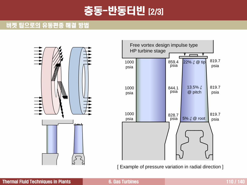
Free vortex design impulse type
HP turbine stage
22% @ tip
13.5%
@ pitch
5% @ root
[ Example of pressure variation in radial direction ]
버켓 팁으로의 유동편중 해결 방법
충동-반동터빈 [2/3]
6. Gas Turbines 111 / 140Thermal Fluid Techniques in Plants
Radial Variation of Flow Parameters
c1 c3
p1 p2 p3
c2
w2R
w2M
w2T
uR
uM
uT
c2R
c2M
c2T
충동-반동터빈 [3/3]
6. Gas Turbines 112 / 140Thermal Fluid Techniques in Plants
크립 [1/4]
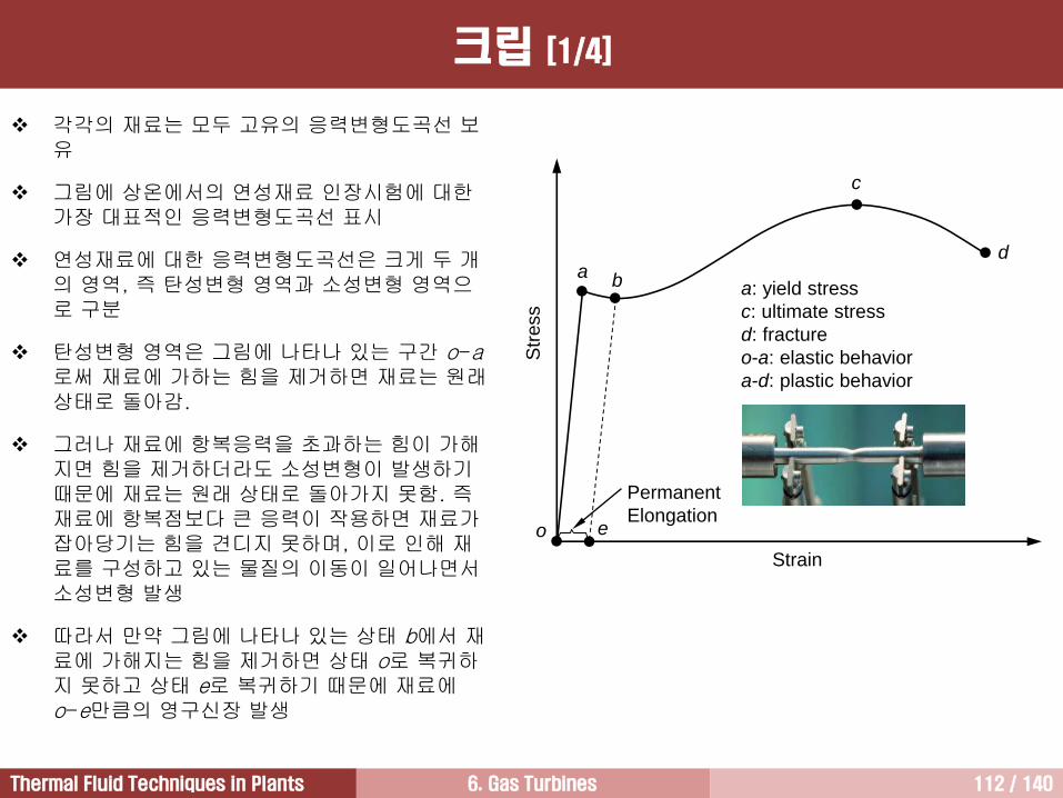
각각의 재료는 모두 고유의 응력변형도곡선 보유
그림에 상온에서의 연성재료 인장시험에 대한가장 대표적인 응력변형도곡선 표시
연성재료에 대한 응력변형도곡선은 크게 두 개의 영역, 즉 탄성변형 영역과 소성변형 영역으로 구분
탄성변형 영역은 그림에 나타나 있는 구간 o-a로써 재료에 가하는 힘을 제거하면 재료는 원래상태로 돌아감.
그러나 재료에 항복응력을 초과하는 힘이 가해지면 힘을 제거하더라도 소성변형이 발생하기때문에 재료는 원래 상태로 돌아가지 못함. 즉재료에 항복점보다 큰 응력이 작용하면 재료가잡아당기는 힘을 견디지 못하며, 이로 인해 재료를 구성하고 있는 물질의 이동이 일어나면서소성변형 발생
따라서 만약 그림에 나타나 있는 상태 b에서 재료에 가해지는 힘을 제거하면 상태 o로 복귀하지 못하고 상태 e로 복귀하기 때문에 재료에o-e만큼의 영구신장 발생
o
Permanent
Elongation
a b
c
d
Str
ess
Strain
a: yield stress
c: ultimate stress
d: fracture
o-a: elastic behavior
a-d: plastic behavior
e
6. Gas Turbines 113 / 140Thermal Fluid Techniques in Plants
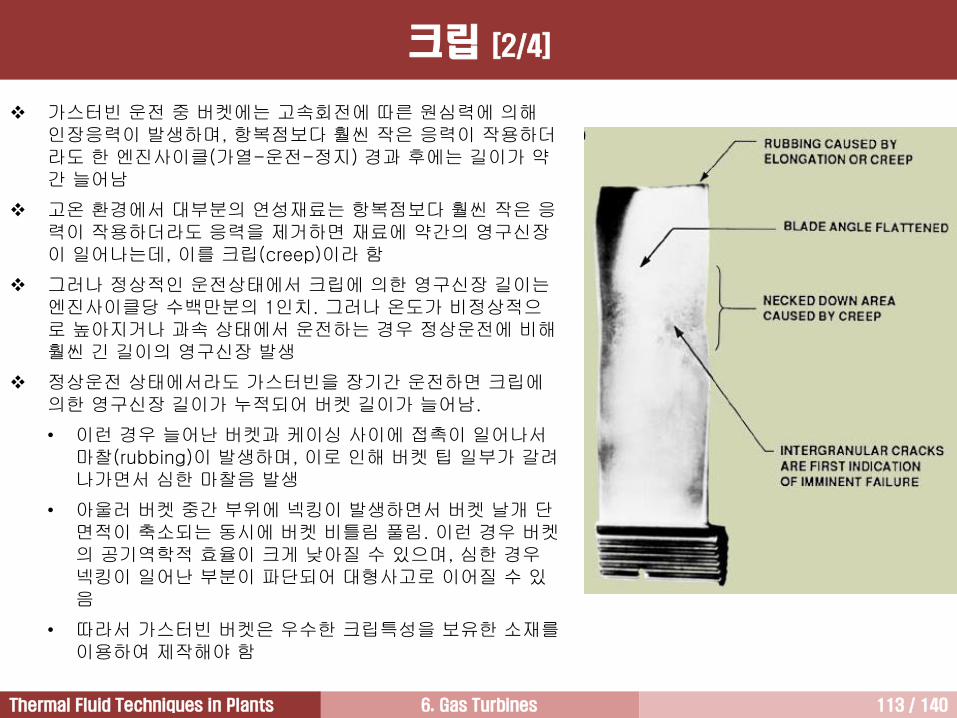
가스터빈 운전 중 버켓에는 고속회전에 따른 원심력에 의해인장응력이 발생하며, 항복점보다 훨씬 작은 응력이 작용하더라도 한 엔진사이클(가열-운전-정지) 경과 후에는 길이가 약간 늘어남
고온 환경에서 대부분의 연성재료는 항복점보다 훨씬 작은 응력이 작용하더라도 응력을 제거하면 재료에 약간의 영구신장이 일어나는데, 이를 크립(creep)이라 함
그러나 정상적인 운전상태에서 크립에 의한 영구신장 길이는엔진사이클당 수백만분의 1인치. 그러나 온도가 비정상적으로 높아지거나 과속 상태에서 운전하는 경우 정상운전에 비해훨씬 긴 길이의 영구신장 발생
정상운전 상태에서라도 가스터빈을 장기간 운전하면 크립에의한 영구신장 길이가 누적되어 버켓 길이가 늘어남.
• 이런 경우 늘어난 버켓과 케이싱 사이에 접촉이 일어나서마찰(rubbing)이 발생하며, 이로 인해 버켓 팁 일부가 갈려나가면서 심한 마찰음 발생
• 아울러 버켓 중간 부위에 넥킹이 발생하면서 버켓 날개 단면적이 축소되는 동시에 버켓 비틀림 풀림. 이런 경우 버켓의 공기역학적 효율이 크게 낮아질 수 있으며, 심한 경우넥킹이 일어난 부분이 파단되어 대형사고로 이어질 수 있음
• 따라서 가스터빈 버켓은 우수한 크립특성을 보유한 소재를이용하여 제작해야 함
크립 [2/4]
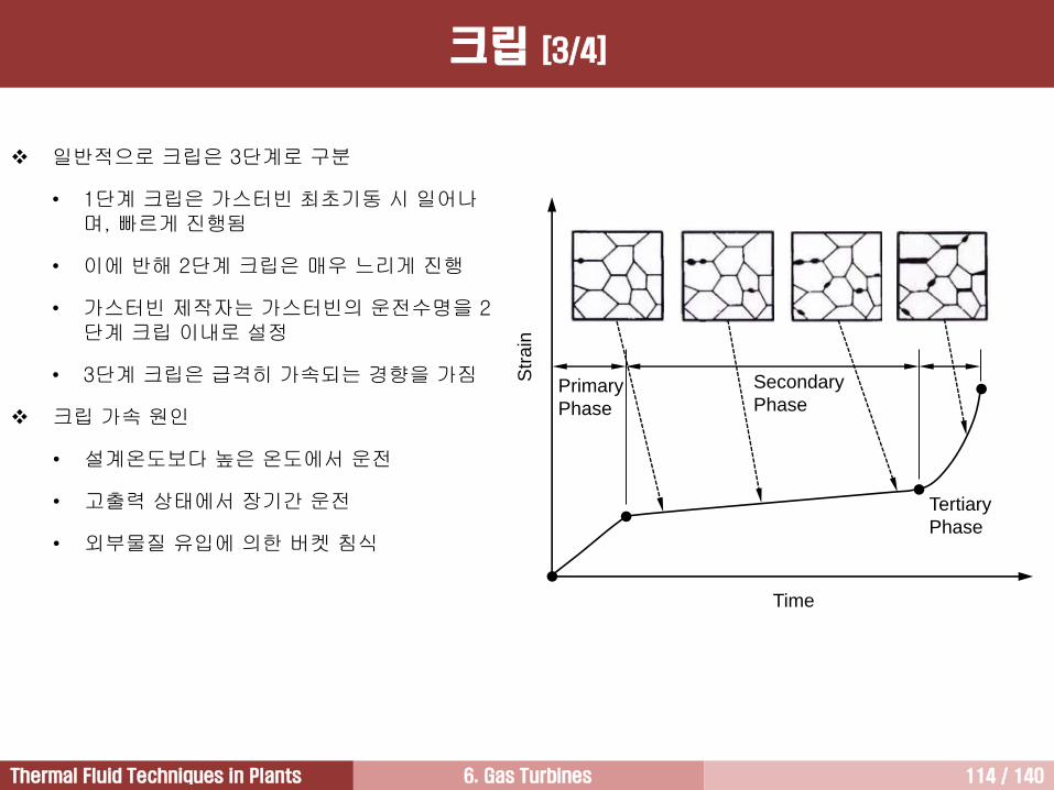
6. Gas Turbines 114 / 140Thermal Fluid Techniques in Plants
Str
ain
Primary
Phase
Tertiary
Phase
Time
Secondary
Phase
일반적으로 크립은 3단계로 구분
• 1단계 크립은 가스터빈 최초기동 시 일어나며, 빠르게 진행됨
• 이에 반해 2단계 크립은 매우 느리게 진행
• 가스터빈 제작자는 가스터빈의 운전수명을 2단계 크립 이내로 설정
• 3단계 크립은 급격히 가속되는 경향을 가짐
크립 가속 원인
• 설계온도보다 높은 온도에서 운전
• 고출력 상태에서 장기간 운전
• 외부물질 유입에 의한 버켓 침식
크립 [3/4]
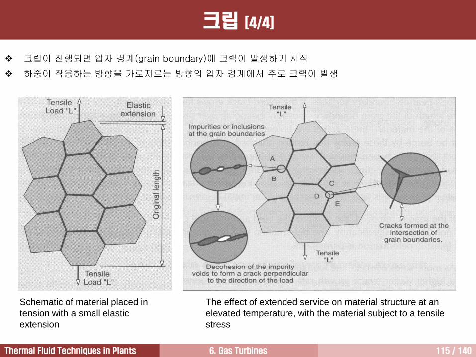
6. Gas Turbines 115 / 140Thermal Fluid Techniques in Plants
Schematic of material placed in
tension with a small elastic
extension
The effect of extended service on material structure at an
elevated temperature, with the material subject to a tensile
stress
크립이 진행되면 입자 경계(grain boundary)에 크랙이 발생하기 시작
하중이 작용하는 방향을 가로지르는 방향의 입자 경계에서 주로 크랙이 발생
크립 [4/4]
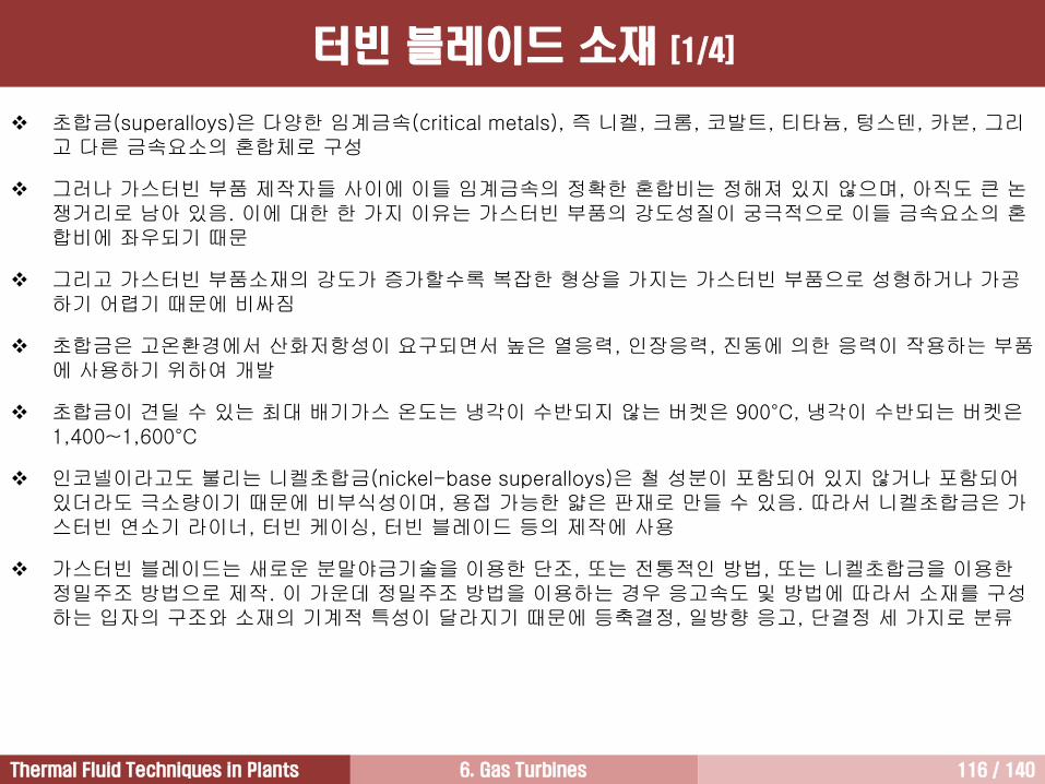
6. Gas Turbines 116 / 140Thermal Fluid Techniques in Plants
터빈 블레이드 소재 [1/4]
초합금(superalloys)은 다양한 임계금속(critical metals), 즉 니켈, 크롬, 코발트, 티타늄, 텅스텐, 카본, 그리고 다른 금속요소의 혼합체로 구성
그러나 가스터빈 부품 제작자들 사이에 이들 임계금속의 정확한 혼합비는 정해져 있지 않으며, 아직도 큰 논쟁거리로 남아 있음. 이에 대한 한 가지 이유는 가스터빈 부품의 강도성질이 궁극적으로 이들 금속요소의 혼합비에 좌우되기 때문
그리고 가스터빈 부품소재의 강도가 증가할수록 복잡한 형상을 가지는 가스터빈 부품으로 성형하거나 가공하기 어렵기 때문에 비싸짐
초합금은 고온환경에서 산화저항성이 요구되면서 높은 열응력, 인장응력, 진동에 의한 응력이 작용하는 부품에 사용하기 위하여 개발
초합금이 견딜 수 있는 최대 배기가스 온도는 냉각이 수반되지 않는 버켓은 900°C, 냉각이 수반되는 버켓은1,400~1,600°C
인코넬이라고도 불리는 니켈초합금(nickel-base superalloys)은 철 성분이 포함되어 있지 않거나 포함되어있더라도 극소량이기 때문에 비부식성이며, 용접 가능한 얇은 판재로 만들 수 있음. 따라서 니켈초합금은 가스터빈 연소기 라이너, 터빈 케이싱, 터빈 블레이드 등의 제작에 사용
가스터빈 블레이드는 새로운 분말야금기술을 이용한 단조, 또는 전통적인 방법, 또는 니켈초합금을 이용한정밀주조 방법으로 제작. 이 가운데 정밀주조 방법을 이용하는 경우 응고속도 및 방법에 따라서 소재를 구성하는 입자의 구조와 소재의 기계적 특성이 달라지기 때문에 등축결정, 일방향 응고, 단결정 세 가지로 분류
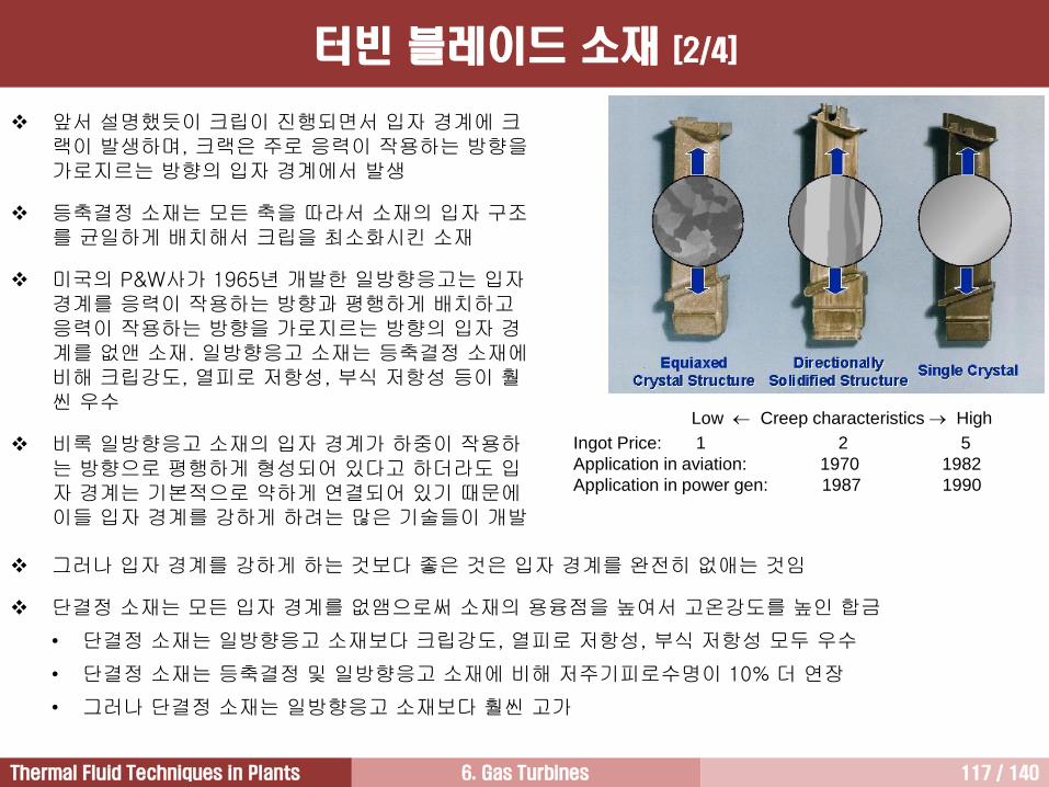
6. Gas Turbines 117 / 140Thermal Fluid Techniques in Plants
앞서 설명했듯이 크립이 진행되면서 입자 경계에 크랙이 발생하며, 크랙은 주로 응력이 작용하는 방향을가로지르는 방향의 입자 경계에서 발생
등축결정 소재는 모든 축을 따라서 소재의 입자 구조를 균일하게 배치해서 크립을 최소화시킨 소재
미국의 P&W사가 1965년 개발한 일방향응고는 입자경계를 응력이 작용하는 방향과 평행하게 배치하고응력이 작용하는 방향을 가로지르는 방향의 입자 경계를 없앤 소재. 일방향응고 소재는 등축결정 소재에비해 크립강도, 열피로 저항성, 부식 저항성 등이 훨씬 우수
비록 일방향응고 소재의 입자 경계가 하중이 작용하는 방향으로 평행하게 형성되어 있다고 하더라도 입자 경계는 기본적으로 약하게 연결되어 있기 때문에이들 입자 경계를 강하게 하려는 많은 기술들이 개발
그러나 입자 경계를 강하게 하는 것보다 좋은 것은 입자 경계를 완전히 없애는 것임
단결정 소재는 모든 입자 경계를 없앰으로써 소재의 용융점을 높여서 고온강도를 높인 합금
• 단결정 소재는 일방향응고 소재보다 크립강도, 열피로 저항성, 부식 저항성 모두 우수
• 단결정 소재는 등축결정 및 일방향응고 소재에 비해 저주기피로수명이 10% 더 연장
• 그러나 단결정 소재는 일방향응고 소재보다 훨씬 고가
Low Creep characteristics High
Ingot Price: 1 2 5
Application in aviation: 1970 1982
Application in power gen: 1987 1990
터빈 블레이드 소재 [2/4]
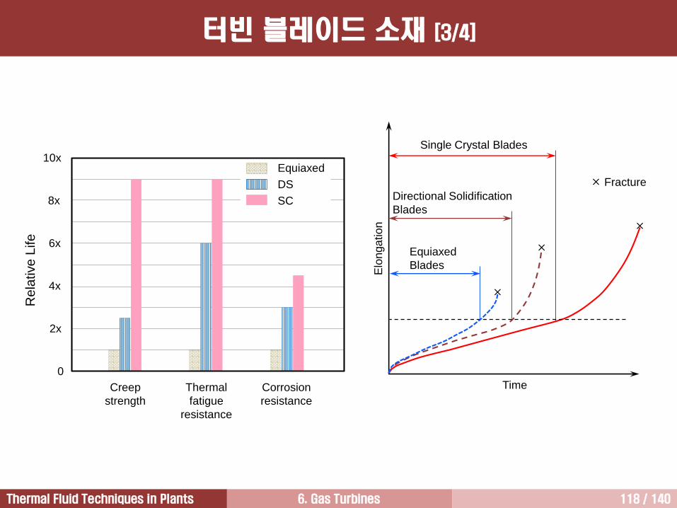
6. Gas Turbines 118 / 140Thermal Fluid Techniques in Plants
Single Crystal Blades
Directional Solidification
Blades
Equiaxed
Blades
TimeE
lon
ga
tio
n
Fracture
Equiaxed
DS
SC
Creep
strength
Thermal
fatigue
resistance
Corrosion
resistance
Rela
tive L
ife
0
2x
4x
6x
8x
10x
터빈 블레이드 소재 [3/4]
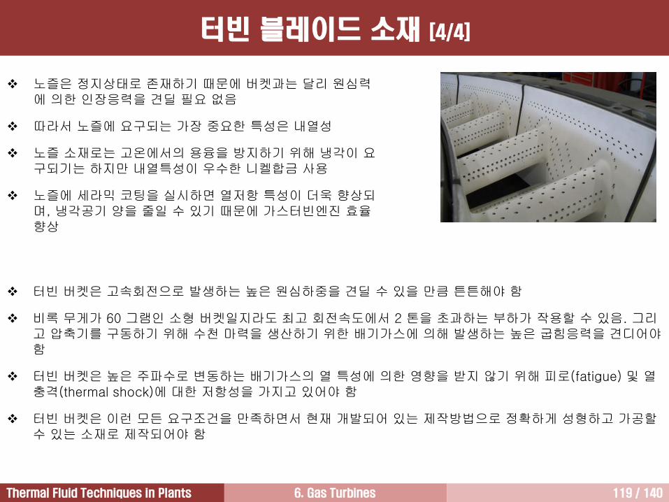
6. Gas Turbines 119 / 140Thermal Fluid Techniques in Plants
노즐은 정지상태로 존재하기 때문에 버켓과는 달리 원심력에 의한 인장응력을 견딜 필요 없음
따라서 노즐에 요구되는 가장 중요한 특성은 내열성
노즐 소재로는 고온에서의 용융을 방지하기 위해 냉각이 요구되기는 하지만 내열특성이 우수한 니켈합금 사용
노즐에 세라믹 코팅을 실시하면 열저항 특성이 더욱 향상되며, 냉각공기 양을 줄일 수 있기 때문에 가스터빈엔진 효율향상
터빈 버켓은 고속회전으로 발생하는 높은 원심하중을 견딜 수 있을 만큼 튼튼해야 함
비록 무게가 60 그램인 소형 버켓일지라도 최고 회전속도에서 2 톤을 초과하는 부하가 작용할 수 있음. 그리고 압축기를 구동하기 위해 수천 마력을 생산하기 위한 배기가스에 의해 발생하는 높은 굽힘응력을 견디어야함
터빈 버켓은 높은 주파수로 변동하는 배기가스의 열 특성에 의한 영향을 받지 않기 위해 피로(fatigue) 및 열충격(thermal shock)에 대한 저항성을 가지고 있어야 함
터빈 버켓은 이런 모든 요구조건을 만족하면서 현재 개발되어 있는 제작방법으로 정확하게 성형하고 가공할수 있는 소재로 제작되어야 함
터빈 블레이드 소재 [4/4]
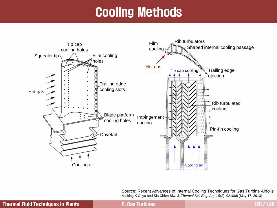
6. Gas Turbines 120 / 140Thermal Fluid Techniques in Plants
Cooling Methods
Source: Recent Advances of Internal Cooling Techniques for Gas Turbine Airfoils Minking K Chyu and Sin Chien Siw, J. Thermal Sci. Eng. Appl. 5(2), 021008 (May 17, 2013)
Tip cap
cooling holes
Film cooling
holes
Trailing edge
cooling slots
Blade platform
cooling holesImpingement
cooling
Dovetail
Cooling air
Squealer tip
Hot gas
Film
cooling
Rib turbulators
Shaped internal cooling passage
Trailing edge
ejection
Tip cap cooling
Rib turbulated
cooling
Pin-fin cooling
Cooling air
Hot gas
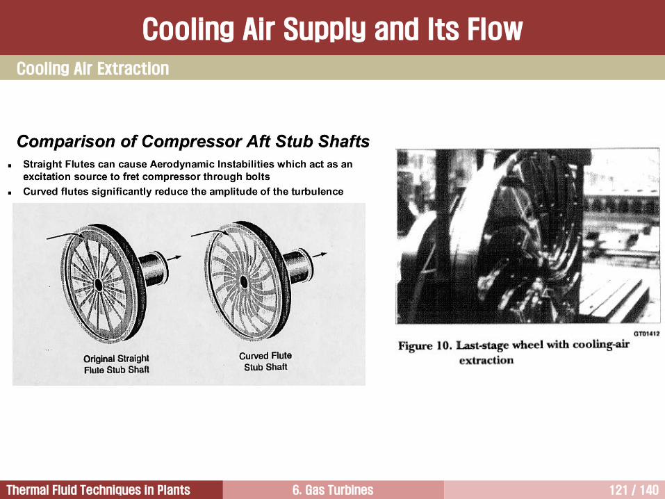
6. Gas Turbines 121 / 140Thermal Fluid Techniques in Plants
Cooling Air Extraction
Cooling Air Supply and Its Flow
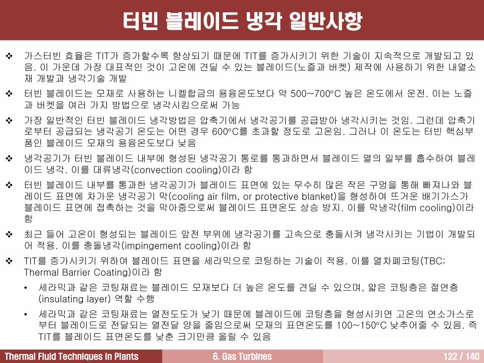
6. Gas Turbines 122 / 140Thermal Fluid Techniques in Plants
터빈 블레이드 냉각 일반사항
가스터빈 효율은 TIT가 증가할수록 향상되기 때문에 TIT를 증가시키기 위한 기술이 지속적으로 개발되고 있음. 이 가운데 가장 대표적인 것이 고온에 견딜 수 있는 블레이드(노즐과 버켓) 제작에 사용하기 위한 내열소재 개발과 냉각기술 개발
터빈 블레이드는 모재로 사용하는 니켈합금의 용융온도보다 약 500~700C 높은 온도에서 운전. 이는 노즐과 버켓을 여러 가지 방법으로 냉각시킴으로써 가능
가장 일반적인 터빈 블레이드 냉각방법은 압축기에서 냉각공기를 공급받아 냉각시키는 것임. 그런데 압축기로부터 공급되는 냉각공기 온도는 어떤 경우 600C를 초과할 정도로 고온임. 그러나 이 온도는 터빈 핵심부품인 블레이드 모재의 용융온도보다 낮음
냉각공기가 터빈 블레이드 내부에 형성된 냉각공기 통로를 통과하면서 블레이드 열의 일부를 흡수하여 블레이드 냉각. 이를 대류냉각(convection cooling)이라 함
터빈 블레이드 내부를 통과한 냉각공기가 블레이드 표면에 있는 무수히 많은 작은 구멍을 통해 빠져나와 블레이드 표면에 차가운 냉각공기 막(cooling air film, or protective blanket)을 형성하여 뜨거운 배기가스가블레이드 표면에 접촉하는 것을 막아줌으로써 블레이드 표면온도 상승 방지. 이를 막냉각(film cooling)이라함
최근 들어 고온이 형성되는 블레이드 앞전 부위에 냉각공기를 고속으로 충돌시켜 냉각시키는 기법이 개발되어 적용. 이를 충돌냉각(impingement cooling)이라 함
TIT를 증가시키기 위하여 블레이드 표면을 세라믹으로 코팅하는 기술이 적용. 이를 열차폐코팅(TBC; Thermal Barrier Coating)이라 함
• 세라믹과 같은 코팅재료는 블레이드 모재보다 더 높은 온도를 견딜 수 있으며, 얇은 코팅층은 절연층(insulating layer) 역할 수행
• 세라믹과 같은 코팅재료는 열전도도가 낮기 때문에 블레이드에 코팅층을 형성시키면 고온의 연소가스로부터 블레이드로 전달되는 열전달 양을 줄임으로써 모재의 표면온도를 100~150C 낮추어줄 수 있음. 즉TIT를 블레이드 표면온도를 낮춘 크기만큼 올릴 수 있음
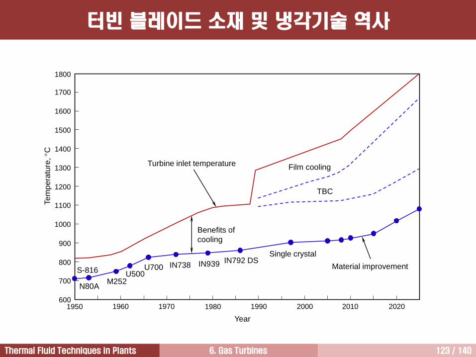
6. Gas Turbines 123 / 140Thermal Fluid Techniques in Plants
Te
mp
era
ture
, C
1800
Year
1950 1960 1970 1980 1990 2000 2010 2020
1700
1600
1500
1400
1300
1200
1100
1000
900
800
700
600
S-816
N80AM252
U500U700 IN738 IN939 IN792 DS
Single crystal
Material improvement
TBC
Film coolingTurbine inlet temperature
Benefits of
cooling
터빈 블레이드 소재 및 냉각기술 역사
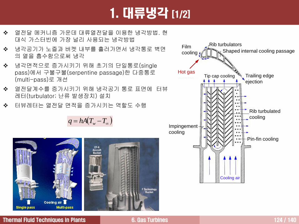
6. Gas Turbines 124 / 140Thermal Fluid Techniques in Plants
Impingement
cooling
Film
cooling
Rib turbulators
Shaped internal cooling passage
Trailing edge
ejection
Tip cap cooling
Rib turbulated
cooling
Pin-fin cooling
Cooling air
Hot gas
열전달 메커니즘 가운데 대류열전달을 이용한 냉각방법. 현대식 가스터빈에 가장 널리 사용되는 냉각방법
냉각공기가 노즐과 버켓 내부를 흘러가면서 냉각통로 벽면의 열을 흡수함으로써 냉각
냉각면적으로 증가시키기 위해 초기의 단일통로(single pass)에서 구불구불(serpentine passage)한 다중통로(multi-pass)로 개선
열전달계수를 증가시키기 위해 냉각공기 통로 표면에 터뷰레터(turbulator; 난류 발생장치) 설치
터뷰레터는 열전달 면적을 증가시키는 역할도 수행
TThAq w
1. 대류냉각 [1/2]
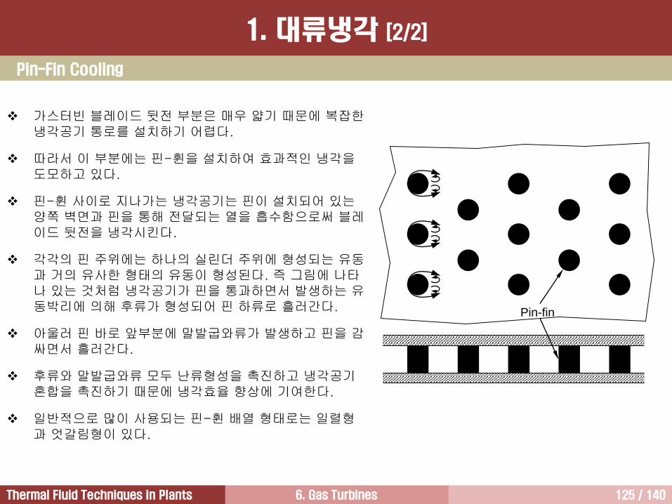
6. Gas Turbines 125 / 140Thermal Fluid Techniques in Plants
가스터빈 블레이드 뒷전 부분은 매우 얇기 때문에 복잡한냉각공기 통로를 설치하기 어렵다.
따라서 이 부분에는 핀-휜을 설치하여 효과적인 냉각을도모하고 있다.
핀-휜 사이로 지나가는 냉각공기는 핀이 설치되어 있는양쪽 벽면과 핀을 통해 전달되는 열을 흡수함으로써 블레이드 뒷전을 냉각시킨다.
각각의 핀 주위에는 하나의 실린더 주위에 형성되는 유동과 거의 유사한 형태의 유동이 형성된다. 즉 그림에 나타나 있는 것처럼 냉각공기가 핀을 통과하면서 발생하는 유동박리에 의해 후류가 형성되어 핀 하류로 흘러간다.
아울러 핀 바로 앞부분에 말발굽와류가 발생하고 핀을 감싸면서 흘러간다.
후류와 말발굽와류 모두 난류형성을 촉진하고 냉각공기혼합을 촉진하기 때문에 냉각효율 향상에 기여한다.
일반적으로 많이 사용되는 핀-휜 배열 형태로는 일렬형과 엇갈림형이 있다.
Pin-fin
Pin-Fin Cooling
1. 대류냉각 [2/2]
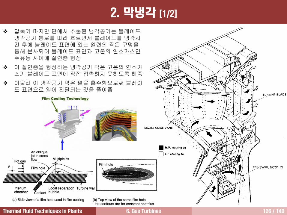
6. Gas Turbines 126 / 140Thermal Fluid Techniques in Plants
2. 막냉각 [1/2]
압축기 마지만 단에서 추출된 냉각공기는 블레이드냉각공기 통로를 따라 흐르면서 블레이드를 냉각시킨 후에 블레이드 표면에 있는 일련의 작은 구멍을통해 분사되어 블레이드 표면과 고온의 연소가스인주유동 사이에 절연층 형성
이 절연층을 형성하는 냉각공기 막은 고온의 연소가스가 블레이드 표면에 직접 접촉하지 못하도록 해줌
아울러 이 냉각공기 막은 열을 흡수함으로써 블레이드 표면으로 열이 전달되는 것을 줄여줌
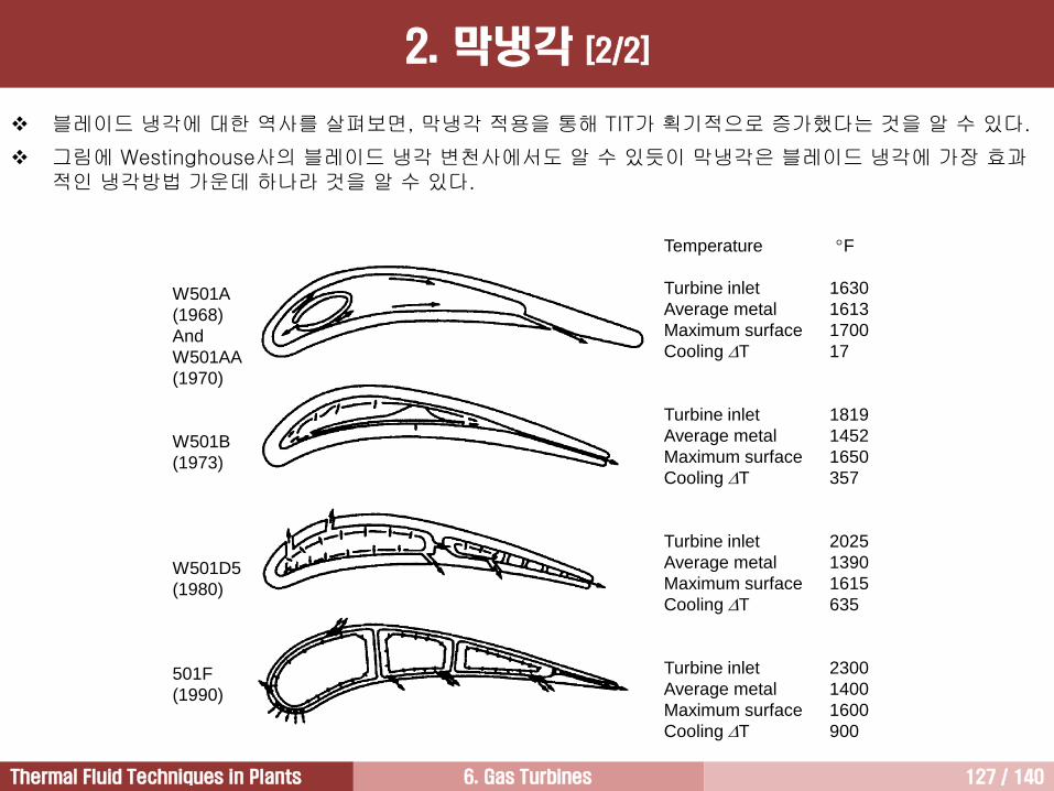
6. Gas Turbines 127 / 140Thermal Fluid Techniques in Plants
Temperature F
Turbine inlet 1630
Average metal 1613
Maximum surface 1700
Cooling T 17
Turbine inlet 1819
Average metal 1452
Maximum surface 1650
Cooling T 357
Turbine inlet 2025
Average metal 1390
Maximum surface 1615
Cooling T 635
Turbine inlet 2300
Average metal 1400
Maximum surface 1600
Cooling T 900
W501A
(1968)
And
W501AA
(1970)
W501B
(1973)
W501D5
(1980)
501F
(1990)
블레이드 냉각에 대한 역사를 살펴보면, 막냉각 적용을 통해 TIT가 획기적으로 증가했다는 것을 알 수 있다.
그림에 Westinghouse사의 블레이드 냉각 변천사에서도 알 수 있듯이 막냉각은 블레이드 냉각에 가장 효과적인 냉각방법 가운데 하나라 것을 알 수 있다.
2. 막냉각 [2/2]
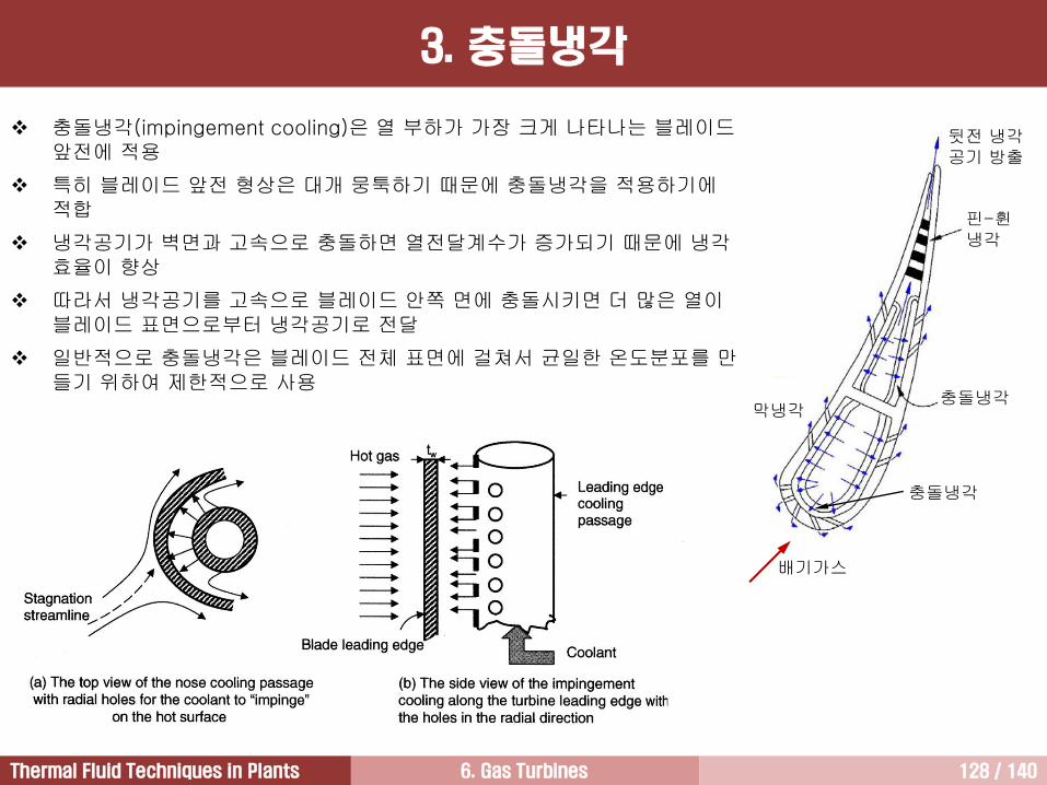
6. Gas Turbines 128 / 140Thermal Fluid Techniques in Plants
3. 충돌냉각
충돌냉각(impingement cooling)은 열 부하가 가장 크게 나타나는 블레이드앞전에 적용
특히 블레이드 앞전 형상은 대개 뭉툭하기 때문에 충돌냉각을 적용하기에적합
냉각공기가 벽면과 고속으로 충돌하면 열전달계수가 증가되기 때문에 냉각효율이 향상
따라서 냉각공기를 고속으로 블레이드 안쪽 면에 충돌시키면 더 많은 열이블레이드 표면으로부터 냉각공기로 전달
일반적으로 충돌냉각은 블레이드 전체 표면에 걸쳐서 균일한 온도분포를 만들기 위하여 제한적으로 사용
배기가스
충돌냉각
뒷전 냉각공기 방출
핀-휜냉각
충돌냉각막냉각
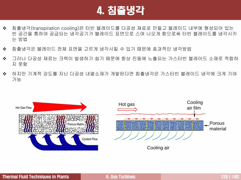
6. Gas Turbines 129 / 140Thermal Fluid Techniques in Plants
4. 침출냉각
침출냉각(transpiration cooling)은 터빈 블레이드를 다공성 재료로 만들고 블레이드 내부에 형성되어 있는빈 공간을 통하여 공급되는 냉각공기가 블레이드 표면으로 스며 나오게 함으로써 터빈 블레이드를 냉각시키는 방법
침출냉각은 블레이드 전체 표면을 고르게 냉각시킬 수 있기 때문에 효과적인 냉각방법
그러나 다공성 재료는 크랙이 발생하기 쉽기 때문에 항상 진동에 노출되는 가스터빈 블레이드 소재로 적합하지 못함
하지만 기계적 강도를 지닌 다공성 내열소재가 개발된다면 침출냉각은 가스터빈 블레이드 냉각에 크게 기여가능
Cooling
air film
Cooling air
Hot gas
Porous
material
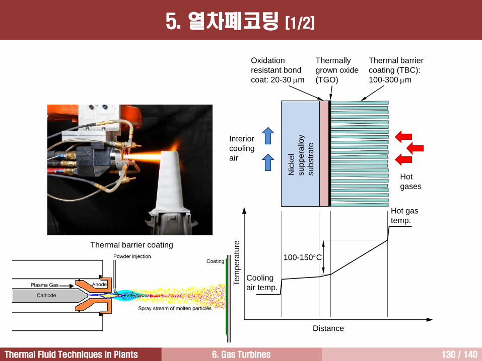
6. Gas Turbines 130 / 140Thermal Fluid Techniques in Plants
Thermal barrier
coating (TBC):
100-300 m
Oxidation
resistant bond
coat: 20-30 m
Thermally
grown oxide
(TGO)
Hot
gases
Interior
cooling
air
Nic
ke
l
su
pp
era
lloy
su
bstr
ate
Te
mp
era
tureThermal barrier coating
100-150C
Cooling
air temp.
Hot gas
temp.
Distance
5. 열차폐코팅 [1/2]
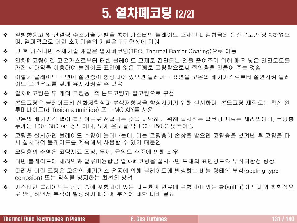
6. Gas Turbines 131 / 140Thermal Fluid Techniques in Plants
일방향응고 및 단결정 주조기술 개발을 통해 가스터빈 블레이드 소재인 니켈합금의 운전온도가 상승하였으며, 결과적으로 이런 소재기술의 개발은 TIT 향상에 기여
그 후 가스터빈 소재기술 개발은 열차폐코팅(TBC; Thermal Barrier Coating)으로 이동
열차폐코팅이란 고온가스로부터 터빈 블레이드 모재로 전달되는 열을 줄여주기 위해 매우 낮은 열전도도를가진 세라믹을 이용하여 블레이드 표면에 얇은 두께로 코팅함으로써 절연층을 만들어 주는 것임
이렇게 블레이드 표면에 절연층이 형성되어 있으면 블레이드 표면을 고온의 배기가스로부터 절연시켜 블레이드 표면온도를 낮게 유지시켜줄 수 있음
열차폐코팅은 두 개의 코팅층, 즉 본드코팅과 탑코팅으로 구성
본드코팅은 블레이드의 산화저항성과 부식저항성을 향상시키기 위해 실시하며, 본드코팅 재질로는 확산 알루미나이드(diffusion aluminide) 또는 MCrAlY를 사용
고온의 배기가스 열이 블레이드로 전달되는 것을 차단하기 위해 실시하는 탑코팅 재료는 세라믹이며, 코팅층두께는 100~300 μm 정도이며, 모재 온도를 약 100~150°C 낮추어줌
코팅을 실시하면 블레이드 수명이 늘어나는데, 이는 코팅층이 손상을 받으면 코팅층을 벗겨낸 후 코팅을 다시 실시하여 블레이드를 계속해서 사용할 수 있기 때문임
코팅층의 수명은 코팅재료 조성, 두께, 균일도 수준에 의해 좌우
터빈 블레이드에 세라믹과 알루미늄합금 열차폐코팅을 실시하면 모재의 표면강도와 부식저항성 향상
따라서 이런 코팅은 고온의 배기가스 유동에 의해 블레이드에 발생하는 비늘 형태의 부식(scaling type corrosion) 또는 침식을 방지하는 최선의 방법
가스터빈 블레이드는 공기 중에 포함되어 있는 나트륨과 연료에 포함되어 있는 황(sulfur)이 모재와 화학적으로 반응하면서 부식이 발생하기 때문에 부식에 대한 대비 필요
5. 열차폐코팅 [2/2]
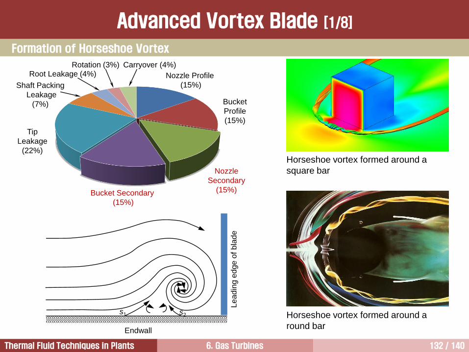
6. Gas Turbines 132 / 140Thermal Fluid Techniques in Plants
Endwall
Le
ad
ing e
dge
of
bla
de
s1 s2
Advanced Vortex Blade [1/8]
Horseshoe vortex formed around a
square bar
Horseshoe vortex formed around a
round bar
Nozzle Profile
(15%)
Bucket
Profile
(15%)
Nozzle
Secondary
(15%)Bucket Secondary
(15%)
Tip
Leakage
(22%)
Shaft Packing
Leakage
(7%)
Root Leakage (4%)Rotation (3%) Carryover (4%)
Formation of Horseshoe Vortex
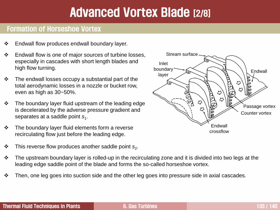
6. Gas Turbines 133 / 140Thermal Fluid Techniques in Plants
Endwall flow produces endwall boundary layer.
Endwall flow is one of major sources of turbine losses,
especially in cascades with short length blades and
high flow turning.
The endwall losses occupy a substantial part of the
total aerodynamic losses in a nozzle or bucket row,
even as high as 30~50%.
The boundary layer fluid upstream of the leading edge
is decelerated by the adverse pressure gradient and
separates at a saddle point s1.
The boundary layer fluid elements form a reverse
recirculating flow just before the leading edge.
Stream surface
Inlet
boundary
layer
Endwall
crossflow
Endwall
Counter vortex
Passage vortex
This reverse flow produces another saddle point s2.
The upstream boundary layer is rolled-up in the recirculating zone and it is divided into two legs at the
leading edge saddle point of the blade and forms the so-called horseshoe vortex.
Then, one leg goes into suction side and the other leg goes into pressure side in axial cascades.
Formation of Horseshoe Vortex
Advanced Vortex Blade [2/8]
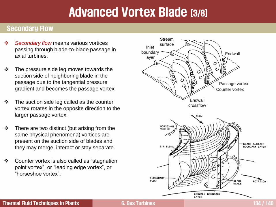
6. Gas Turbines 134 / 140Thermal Fluid Techniques in Plants
Secondary flow means various vortices
passing through blade-to-blade passage in
axial turbines.
The pressure side leg moves towards the
suction side of neighboring blade in the
passage due to the tangential pressure
gradient and becomes the passage vortex.
The suction side leg called as the counter
vortex rotates in the opposite direction to the
larger passage vortex.
There are two distinct (but arising from the
same physical phenomena) vortices are
present on the suction side of blades and
they may merge, interact or stay separate.
Counter vortex is also called as “stagnation
point vortex”, or “leading edge vortex”, or
“horseshoe vortex”.
Stream
surfaceInlet
boundary
layer
Endwall
crossflow
Endwall
Counter vortex
Passage vortex
Secondary Flow
Advanced Vortex Blade [3/8]
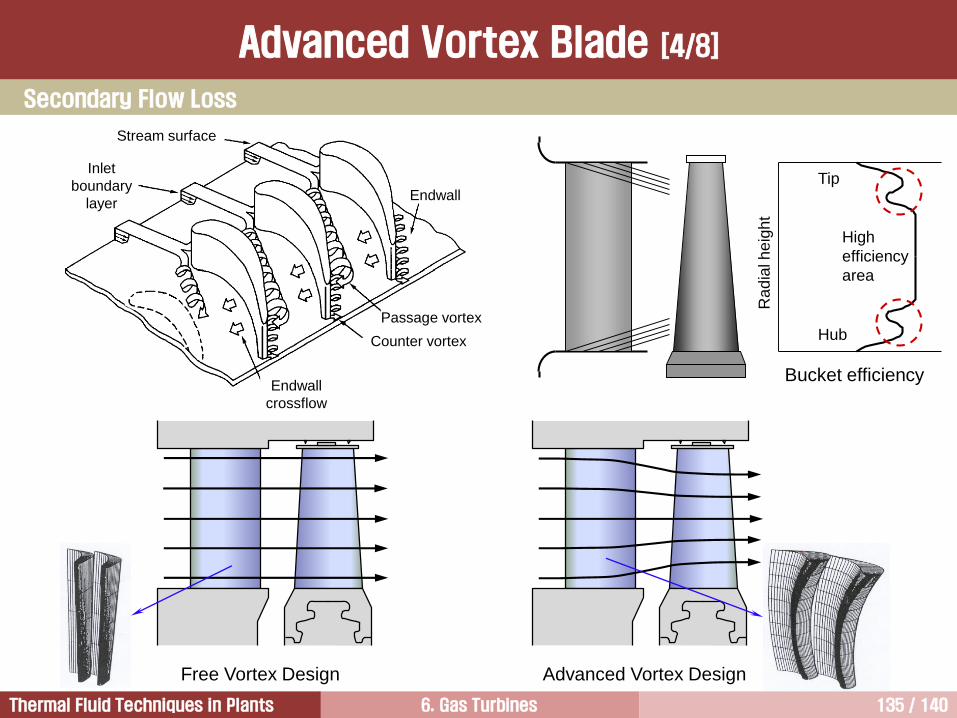
6. Gas Turbines 135 / 140Thermal Fluid Techniques in Plants
Free Vortex Design Advanced Vortex Design
Hub
Tip
High
efficiency
area
Ra
dia
l h
eig
ht
Bucket efficiency
Stream surface
Inlet
boundary
layer
Endwall
crossflow
Endwall
Counter vortex
Passage vortex
Secondary Flow Loss
Advanced Vortex Blade [4/8]
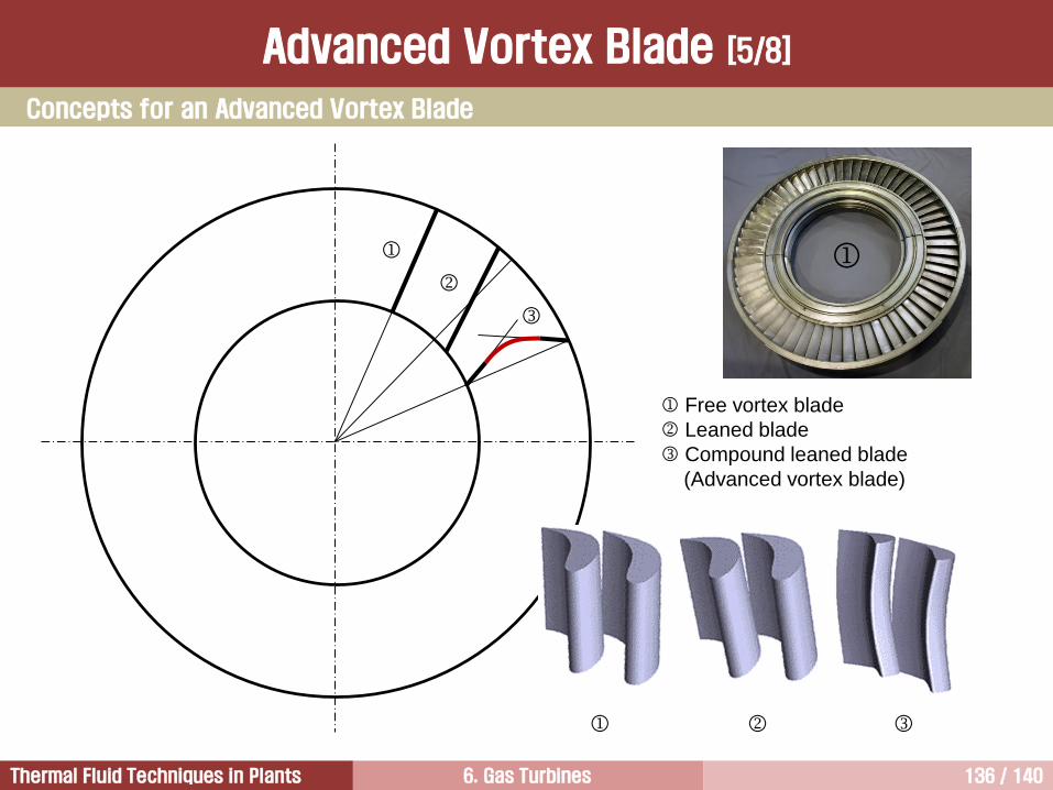
6. Gas Turbines 136 / 140Thermal Fluid Techniques in Plants
Free vortex blade
Leaned blade
Compound leaned blade
(Advanced vortex blade)
Concepts for an Advanced Vortex Blade
Advanced Vortex Blade [5/8]
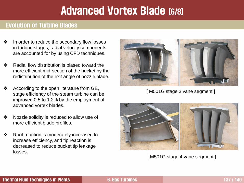
6. Gas Turbines 137 / 140Thermal Fluid Techniques in Plants
[ M501G stage 3 vane segment ]
[ M501G stage 4 vane segment ]
In order to reduce the secondary flow losses
in turbine stages, radial velocity components
are accounted for by using CFD techniques.
Radial flow distribution is biased toward the
more efficient mid-section of the bucket by the
redistribution of the exit angle of nozzle blade.
According to the open literature from GE,
stage efficiency of the steam turbine can be
improved 0.5 to 1.2% by the employment of
advanced vortex blades.
Nozzle solidity is reduced to allow use of
more efficient blade profiles.
Root reaction is moderately increased to
increase efficiency, and tip reaction is
decreased to reduce bucket tip leakage
losses.
Evolution of Turbine Blades
Advanced Vortex Blade [6/8]
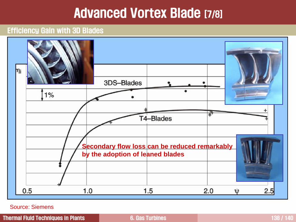
6. Gas Turbines 138 / 140Thermal Fluid Techniques in Plants
Source: Siemens
Secondary flow loss can be reduced remarkably
by the adoption of leaned blades
Efficiency Gain with 3D Blades
Advanced Vortex Blade [7/8]
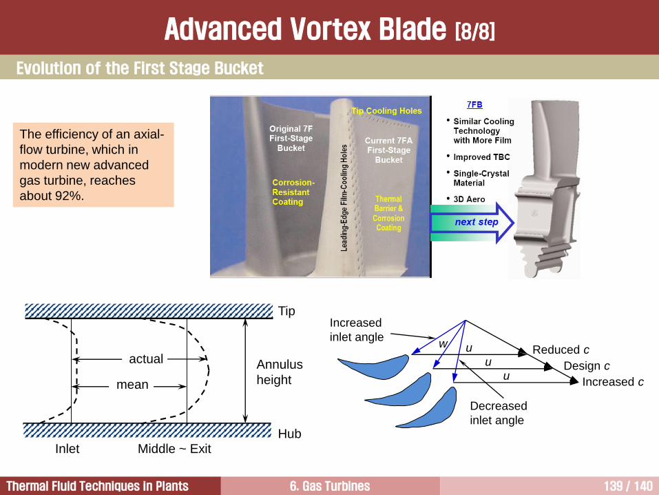
6. Gas Turbines 139 / 140Thermal Fluid Techniques in Plants
The efficiency of an axial-
flow turbine, which in
modern new advanced
gas turbine, reaches
about 92%.
Design c
Increased c
Reduced cu
u
u
w
Increased
inlet angle
Decreased
inlet angleHub
Tip
Annulus
heightmean
actual
Inlet Middle ~ Exit
Evolution of the First Stage Bucket
Advanced Vortex Blade [8/8]

6. Gas Turbines 140 / 140Thermal Fluid Techniques in Plants
질의 및 응답
작성자: 이 병 은 (공학박사)작성일: 2016.02.15 (Ver.1)연락처: [email protected]
Mobile: 010-3122-2262저서: 실무 발전설비 열역학/증기터빈 열유체기술