Embed Size (px)
Citation preview

6 February 2004 1
LAN-50/500 Ethernet Communication

6 February 2004 2
This Presentation Will . . .
• Cover how to configure the LAN-50/500 for use with Doors
• Cover the Pros and Cons to using Doors in a network environment

6 February 2004 3
For Successful Configuration
• You must have a technical knowledge of networking:– Setting IP addresses– Creating shared folders– Creating shortcuts to these shared folders

6 February 2004 4
Networking Caveats
• LAN-50/500 devices are recommended for use over a LAN: Local Area Network. They can be used over the Internet or over an external network segment, but there is a security concern:– Having the LAN device on the Internet or on an
external network segment makes that device available to anyone who knows the device’s MAC/Internet address.

6 February 2004 5
Networking Caveats
• If a device is installed for operation over the Internet or over an external network segment, auto detect and configure software cannot be used. Configuration must be done manually, using Telnet commands. This process is beyond what can be covered in this seminar. – The process is described in Keri document: LAN-
50-LAN-500_Application_Note.pdf, found on the Keri web site or the Keri CD.

6 February 2004 6
Differences Between LAN-50 and -500
• LAN-50– Standalone in-line
module– Use with any PXL
controller (but typically the PXL-250)
• LAN-500– Plug-in module– Use with PXL-500/510
controllers ONLY

6 February 2004 7
LAN-50
• The LAN-50 is used with the PXL-250
• LAN unit plugs into the controller’s RS-232 port
• The LAN-50 can be used with the PXL-500/510 as well

6 February 2004 8
LAN-500
• The LAN-500 is used with the PXL-500
• LAN module plugs directly into TB-13 on the controller

6 February 2004 9
Which Doors Revision
• LAN-50 support begins with Doors v3.61
• LAN-500 support begins with Doors v4.10

6 February 2004 10
Host/Client PC Configuration
• A configuration summary is provided in the next few slides
• For detailed information, refer to the LAN-50/500 Ethernet Communication Application Note– This document can be found on the Doors CD or
on the Keri Systems web site (www.kerisys.com)

6 February 2004 11
Host Workstation Configuration
• Doors software must be installed on the host workstation
• Share the Doors folder on the host workstation
• Doors is not a Client/Server software package

6 February 2004 12
Client Workstation Configuration
• On each client workstation, create a shortcut to the Doors software executable on the shared folder on the host workstation
6 February 2004 13
How Doors Handles its Databases
• Whenever a database is opened, a copy is made
• All work is done to the database copy
• When completed work is saved, the copy overwrites the original

6 February 2004 14
Why Do It This Way?
• This protects the original database should changes be cancelled

6 February 2004 15
Database Caution
• Doors cannot tell if more than one user has opened a database
• If two people edit a database at the same time, the last database saved becomes the active database

6 February 2004 16
Database Caution
• Keri recommends that only one user open a database at a time
• This helps prevent the loss of data by minimizing the possibility of database overwriting

6 February 2004 17
Workstation to Network Communication
• Only ONE workstation can communicate with the access control network at a time– Downloading, Uploading, Monitoring, Manual Operation

6 February 2004 18
Releasing Communication Control
• To allow another user to communicate with the network you must:
– Operate > Net Disconnect
OR
– Close Doors, either OR

6 February 2004 19
LAN-50 Hardware Connection
• Power supply connection• LAN hub connection
– Use a standard patch cable
• PXL controller RS-232 port connection– Use a Keri KDP-336 cable

6 February 2004 20
LAN-500 Hardware Connections
• Remove jumpers JP-6 and JP-7 (upper-right corner of the controller PCB)

6 February 2004 21
LAN-500 Hardware Connections
• Plug the LAN-500 module into TB-13 on the PXL-500 controller
• Connect the LAN hub cable
6 February 2004 22
Assign a LAN Unit an IP Address
• Four things are needed:1. The Lantronix “DeviceInstaller” software must
be installed on the host workstation– The software is found on the Keri CD-ROM
2. Locate the unit’s Ethernet/MAC address– Found on the unit’s label
3. The unit must be powered ON
4. Have a unique, static IP address for the unit– Assigned by your site’s LAN administrator
6 February 2004 23
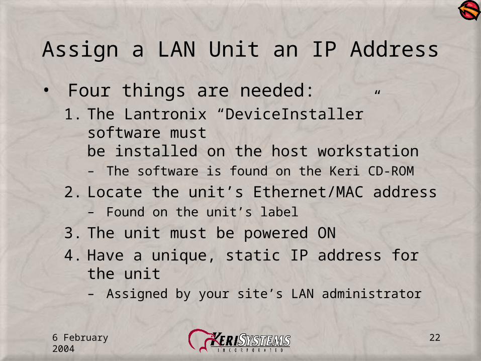
Locating the DeviceInstaller Program
• Locate and run the Lantronix “DeviceInstaller.exe” program in the Lantronix folder of the Keri CD-ROM

6 February 2004 24
Installing the DeviceInstaller Program
• “DeviceInstaller.exe” opens a standard InstallShield wizard
– Follow the wizard’s instructions and install the program
– A program shortcut icon appears on the host workstation’s desktop following installation

6 February 2004 25
LAN-50 Ethernet Address
• Locate the LAN-50 Ethernet/MAC address on the unit’s label– It is displayed in this
format:
xx-xx-xx-xx-xx-xx

6 February 2004 26
LAN-500 Ethernet Address
• Locate the LAN-500 Ethernet/MAC address on the unit’s label– It is displayed in this format: xx-xx-xx-xx-xx-xx

6 February 2004 27
Starting the DeviceInstaller
• With unit power ON and the unit’s IP address and Ethernet/MAC address in hand. . .
• Double-click the shortcut to start the DeviceInstaller program

6 February 2004 28
Checking Existing IP Addresses
• Click the button
• This opens the IP address list window

6 February 2004 29
List the Existing IP Addresses
• Click the button to display a list of already assigned IP addresses in the LAN network– Helps you prevent IP
address duplication– Click the x-box to close
the window after reviewing the list

6 February 2004 30
Assigning the IP Address
• Click the button to open the IP Assignment window

6 February 2004 31
Enter Addressing Information
• Enter the Ethernet/MAC address
• Enter the assigned IP Address

6 February 2004 32
Assign the IP Address
• Once the information is entered, click the button

6 February 2004 33
Successful Assignment
• After a brief delay, an assignment successful window appears
• Click the OK button
• Click the X-box to exit the program

6 February 2004 34
Verify Doors Software Settings
• Click on the button on the Doors toolbar or navigate to the Doors Setup > System > Network Config pull-down menu
• Then click on the tab to open the Network Configuration window

6 February 2004 35
Setting Network Configuration Values
• Verify/Set the following values:– Port = TCP/IP– Server’s Ethernet Port Number = 10021 (default value)– Remote Site TCP/IP Address = IP address of the LAN unit– Remote Site Port Number = 10001
(default is 0, this value must be changed)
• Restart Doors so the program recognizes the new values

6 February 2004 36
Verify Doors/LAN Communication
• Verify communication between Doors and the LAN – Open the Controllers Tab– Perform an Auto-Config
• A successful Auto-Config will display a list of all recognized controllers in the network
6 February 2004 37
If there is No LAN Communication
• Verify cabling and power (for LAN-50) connections
• Verify/Set LAN configuration parameters via the following steps

6 February 2004 38
Configure a LAN Unit
• The LAN unit must have certain operating parameters to ensure proper operation
• This is done through the LAN unit’s Web Manager program
• Use your web browser to enter and verify these parameters

6 February 2004 39
Start the Web Manager Program
• Open your browser program• Enter the LAN unit’s IP address• Press <ENTER>

6 February 2004 40
Connect to the LAN Unit
• After a short delay, the Web Manager program opens
• Click the button to connect to the unit and enable all program menu options

6 February 2004 41
Retrieve Unit Configuration
• Click the button to display the LAN unit’s configuration parameters

6 February 2004 42
Retrieve Server Properties
• Click the button to display the unit’s server properties

6 February 2004 43
Verify Unit IP Address
• Verify the IP address listed matches the IP address of the unit– If it does not, click the button and change it

6 February 2004 44
Retrieve the Port Properties
• Click the button to display the LAN unit’s port properties

6 February 2004 45
Port Property Categories
• Parameters in four of the seven major categories must be verified
1
2
3
5
4
6
7

6 February 2004 46
Verify Serial Port Settings
• Verify the following parameters:– Serial Protocol = RS-232 – Parity = None
– Speed = 9600 – Stop Bit = 1
– Character Size = 8 – Flow Control = None
• If any on-screen value does not match this list, click the button and change it

6 February 2004 47
Verify Connect Mode Settings
• Verify the following parameters:– Incoming Connection = Accept Unconditional– Response = Nothing (Quiet)– Startup = No Active Startup
• If any on-screen value does not match this list, click the button and change it

6 February 2004 48
Verify Dedicated Connection Settings
• Verify the following parameter:– Local Port = 10001
• If any on-screen value does not match this list, click the button and change it

6 February 2004 49
Verify Additional Settings
• Verify the following parameter:– Disconnect Mode = Ignore DTR
• If any on-screen value does not match this list, click the button and change it
6 February 2004 50
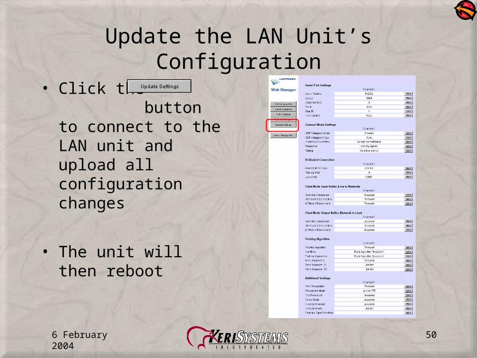
Update the LAN Unit’s Configuration
• Click the button to connect to the LAN unit and upload all configuration changes
• The unit will then reboot

6 February 2004 51
Ready for Operation
• When the Server Properties window appears, the unit is ready for use
• Close the browser window

6 February 2004 52
Verify Doors Software Settings
• Click on the button on the Doors toolbar or navigate to the Doors Setup > System > Network Config pull-down menu
• Then click on the tab to open the Network Configuration window
6 February 2004 53
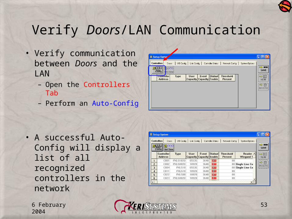
Verify Doors/LAN Communication
• Verify communication between Doors and the LAN – Open the Controllers Tab– Perform an Auto-Config
• A successful Auto-Config will display a list of all recognized controllers in the network

6 February 2004 54
Rebooting Units
• Rebooting restarts the unit should the unit become hung-up
• Press the reset button to reboot a LAN-500 unit
• Cycle unit power to reboot a LAN-50 unit

6 February 2004 55
Resetting Units
• Resetting the unit restores all factory default port parameters– Performing a reset means you will have to
reconfigure the unit
• Resetting the unit must be done via a Telnet connection
6 February 2004 56
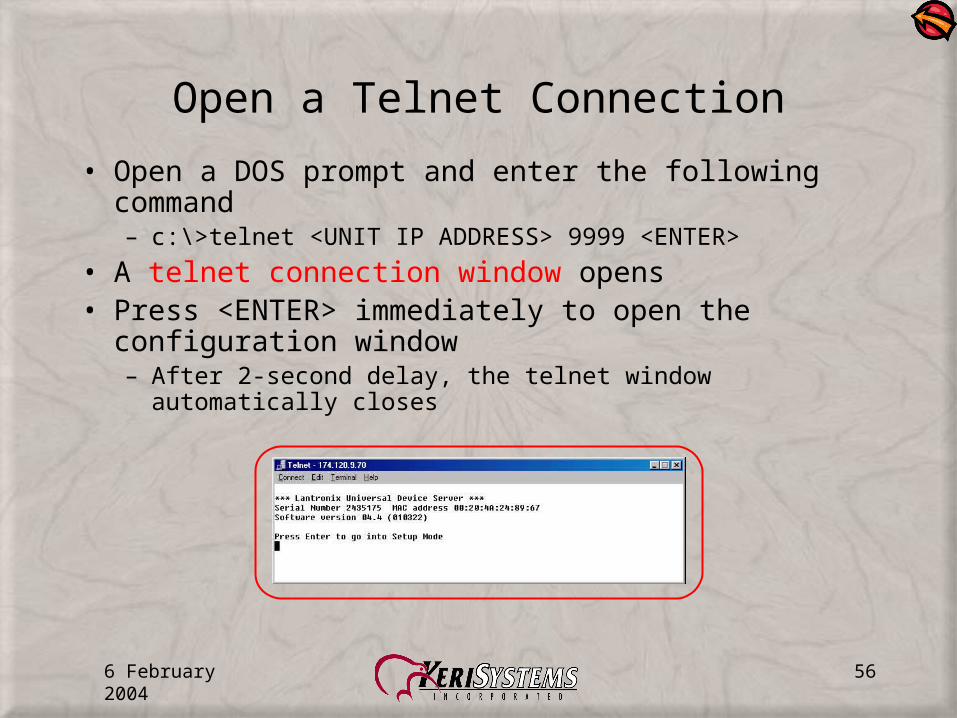
Open a Telnet Connection
• Open a DOS prompt and enter the following command– c:\>telnet <UNIT IP ADDRESS> 9999 <ENTER>
• A telnet connection window opens• Press <ENTER> immediately to open the
configuration window– After 2-second delay, the telnet window automatically closes

6 February 2004 57
Restore Factory Defaults
• All current configuration parameters are displayed• Press 7 <ENTER> to restore factory default values• Press 9 <ENTER> to save these values and exit
Telnet


![Cisco Industrial Ethernet 2000 Series Switches Data · PDF fileCisco Industrial Ethernet 2000 Series Switches ... [TCAM] template) Bidirectional, 128 NAT ... LAN Base to Enhanced LAN](https://img.pdfslide.us/doc/110x75/5a92513c7f8b9af27f8e8993/cisco-industrial-ethernet-2000-series-switches-data-industrial-ethernet-2000-series.jpg)