Embed Size (px)
Citation preview

Design of Steel Structures Prof. S.R.Satish Kumar and Prof. A.R.Santha Kumar
Indian Institute of Technology Madras
6. BEAMS
6.1 Introduction
One of the frequently used structural members is a beam whose main function is
to transfer load principally by means of flexural or bending action. In a structural
framework, it forms the main horizontal member spanning between adjacent columns or
as a secondary member transmitting floor loading to the main beams. Normally only
bending effects are predominant in a beam except in special cases such as crane
girders, where effects of torsion in addition to bending have to be specifically
considered.
The type of responses of a beam subjected to simple uniaxial bending are shown
in Table 6.1. The response in a particular case depends upon the proportions of the
beam, the form of the applied loading and the type of support provided. In addition to
satisfying various strength limits as given in the Table, the beam should also not deflect
too much under the working loads i.e. it has to satisfy the serviceability limit state also.
Recently, IS: 800, the structural steel code has been revised and the limit state
method of design has been adopted in tune with other international codes of practice
such as BS, EURO, and AISC. This chapter attempts to throw light on the provisions for
bending members in this code.

6.2 Limit state design of beams
In the working stress or allowable stress method of design, the emphasis is on
limiting a particular stress in a component to a fraction of the specified strength of the
material of the component. The magnitude of the factor for a structural action depends
upon the degree of safety required. Further, elastic behaviour of the material is
assumed. The main objection to the permissible stress method is that the stress safety
factor relating the permissible stress to the strength of the material is not usually the
same as the ratio of the strength to the design load. Thus it does not give the degree of
safety based on collapse load.
In the limit state method, both collapse condition and serviceability condition are
considered. In this method, the structure has to be designed to withstand safely all
loads and deformations likely to occur on it throughout its life. Designs should ensure
that the structure does not become unfit for the use for which it is required. The state at
which the unfitness occurs is called a limit state. Special features of limit state design
method are:
• It is possible to take into account a number of limit states depending upon the
particular instance
• This method is more general in comparison to the working stress method. In
this method, different safety factors can be applied to different limit states, which is
more rational than applying one common factor (load factor) as in the plastic design
method.
• This concept of design is appropriate for the design of structures since any
new knowledge of the structural behaviour, loading and materials can be readily
incorporated.

The limit state design method is essentially based on the concept of probability.
Its basic feature is to consider the possibility and probability of the collapse load. In this
respect, it is necessary to consider the possibility of reduced strength and increased
load.
Table 6.1 Main failure modes of hot-rolled beams
Category Mode Comments 1 Excessive
bending triggering collapse
This is the basic failure mode provided (1) the beam is prevented from buckling laterally,(2) the component elements are at least compact, so that they do not buckle locally. Such “stocky” beams will collapse by plastic hinge formation.
2 Lateral torsional buckling of long beams which are not suitably braced in the lateral direction.(i.e. “un restrained” beams)
Failure occurs by a combination of lateral deflection and twist. The proportions of the beam, support conditions and the way the load is applied are all factors, which affect failure by lateral torsional buckling.
3 Failure by local buckling of a flange in compression or web due to shear or web under compression due to concentrated loads
Unlikely for hot rolled sections, which are generally stocky. Fabricated box sections may require flange stiffening to prevent premature collapse.
Web stiffening may be required for plate girders to prevent shear buckling.
Load bearing stiffeners are sometimes needed under point loads to resist web buckling.

The object of design is to keep an acceptable level the probability of any limit
state not being exceeded. This is achieved by taking account of the variation in strength
and properties of materials to be used and the variations in the loads to be supported by
the structure, by using the characteristic values of the strength of materials as well as
the loads to be applied. The deviations from the characteristic values in the actual
structures are allowed by using their design values. The characteristic values should be
based on statistical evidence where necessary data are available; where such data are
not available they should be based on an appraisal of experience. The design values
are derived from the characteristic values through the use of partial safety factors, one
for material strengths and the other for loads and load effects.
4 Local failure by
(1) shear yield of web (2) local crushing of web (3) buckling of thin flanges.
Shear yield can only occur in very short spans and suitable web stiffeners will have to be designed.
Local crushing is possible when concentrated loads act on unstiffened thin webs. Suitable stiffeners can be designed.
This is a problem only when very wide flanges are employed. Welding of additional flange plates will reduce the plate b / t ratio and thus flange buckling failure can be avoided.

Design of Steel Structures Prof. S.R.Satish Kumar and Prof. A.R.Santha Kumar
Indian Institute of Technology Madras
6.3 Behaviour of steel beams
Laterally stable steel beams can fail only by (a) Flexure (b) Shear or (c) Bearing,
assuming the local buckling of slender components does not occur. These three
conditions are the criteria for limit state design of steel beams. Steel beams would also
become unserviceable due to excessive deflection and this is classified as a limit state
of serviceability.
The factored design moment, M at any section, in a beam due to external actions
shall satisfy
dM M≤
Where Md = design bending strength of the section
6.3.1 Design strength in bending (Flexure)
The behaviour of members subjected to bending demonstrated in Fig 6.1
Fig 6.1 Beam buckling behaviour
This behaviour can be classified under two parts:

Design of Steel Structures Prof. S.R.Satish Kumar and Prof. A.R.Santha Kumar
Indian Institute of Technology Madras
• When the beam is adequately supported against lateral buckling, the beam
failure occurs by yielding of the material at the point of maximum moment. The beam is
thus capable of reaching its plastic moment capacity under the applied loads. Thus the
design strength is governed by yield stress and the beam is classified as laterally
supported beam.
• Beams have much greater strength and stiffness while bending about the
major axis. Unless they are braced against lateral deflection and twisting, they are
vulnerable to failure by lateral torsional buckling prior to the attainment of their full in-
plane plastic moment capacity. Such beams are classified as laterally supported beam.
Beams which fail by flexual yielding
Type1: Those which are laterally supported
The design bending strength of beams, adequately supported against buckling
(laterally supported beams) is governed by yielding. The bending strength of a laterally
braced compact section is the plastic moment Mp. If the shape has a large shape factor
(ratio of plastic moment to the moment corresponding to the onset of yielding at the
extreme fiber), significant inelastic deformation may occur at service load, if the section
is permitted to reach Mp at factored load. The limit of 1.5My at factored load will control
the amount of inelastic deformation for sections with shape factors greater than 1.5.
This provision is not intended to limit the plastic moment of a hybrid section with a web
yield stress lower than the flange yield stress. Yielding in the web does not result in
significant inelastic deformations.
Type2: Those which are laterally shift
Lateral-torsional buckling cannot occur, if the moment of inertia about the
bending axis is equal to or less than the moment of inertia out of plane. Thus, for
shapes bent about the minor axis and shapes with Iz = Iy such as square or circular

Design of Steel Structures Prof. S.R.Satish Kumar and Prof. A.R.Santha Kumar
Indian Institute of Technology Madras
shapes, the limit state of lateral-torsional buckling is not applicable and yielding controls
provided the section is compact.
6.3.1.1 Laterally supported beam
When the lateral support to the compression flange is adequate, the lateral
buckling of the beam is prevented and the section flexual strength of the beam can be
developed. The strength of I-sections depends upon the width to thickness ratio of the
compression flange. When the width to thickness ratio is sufficiently small, the beam
can be fully plastified and reach the plastic moment, such section are classified as
compact sections. Howeverprovided the section can also sustain the moment during the
additional plastic hinge rotation till the failure mechanism is formed. Such sections are
referred to as plastic sections. When the compression flange width to thickness ratio is
larger, the compression flange may buckle locally before the complete plastification of
the section occurs and the plastic moment is reached. Such sections are referred to as
non-compact sections. When the width to thickness ratio of the compression flange is
sufficiently large, local buckling of compression flange may occur even before extreme
fibre yields. Such sections are referred to as slender sections.
The flexural behaviour of such beams is presented in Fig. 6.2. The section
classified as slender cannot attain the first yield moment, because of a premature local
buckling of the web or flange. The next curve represents the beam classified as 'semi-
compact' in which, extreme fibre stress in the beam attains yield stress but the beam
may fail by local buckling before further plastic redistribution of stress can take place
towards the neutral axis of the beam. The factored design moment is calculated as per
Section 8.2 of the code.
The curve shown as 'compact beam' in which the entire section, both
compression and tension portion of the beam, attains yield stress. Because of this
plastic redistribution of stress, the member o attains its plastic moment capacity (Mp) but
fails by local buckling before developing plastic mechanism by sufficient plastic hinge

Design of Steel Structures Prof. S.R.Satish Kumar and Prof. A.R.Santha Kumar
Indian Institute of Technology Madras
rotation. The moment capacity of such a section can be calculated by provisions given
in Section 8.2.1.2. This provision is for the moment capacity with low shear load.
Fig 6.2 Flexual member performance using section classification
Low shear load is referred to the factored design shear force that does not
exceed 0.6Vd, where Vd is the design shear strength of cross section as explained in
8.2.1.2 of the code.
Fig.6.3 Interaction of high shear and bending moment

Design of Steel Structures Prof. S.R.Satish Kumar and Prof. A.R.Santha Kumar
Indian Institute of Technology Madras
6.3.1.1.1 Holes in the tension zone
The fastener holes in the tension flange need not be allowed for provided that for
the tension flange the condition as given in 8.2.1.4 of the code is satisfied. The
presence of holes in the tension flange of a beam due to connections may lead to
reduction in the bending capacity of the beam.
6.3.1.1.2 Shear lag effects
The simple theory of bending is based on the assumption that plane sections
remain plane after bending. But, the presence of shear strains causes the section to
warp. Its effect in the flanges is to modify the bending stresses obtained by the simple
theory, producing higher stresses near the junction of a web and lower stresses at
points away from it (Fig. 6.4). This effect is called ‘shear lag’. This effect is minimal in
rolled sections, which have narrow and thick flanges and more pronounced in plate
girders or box sections having wide thin flanges when they are subjected to high shear
forces, especially in the vicinity of concentrated loads. The provision with regard to
shear lag effects is given in 8.2.1.5.
Fig.6.4 Shear Lag effects
6.3.2 Laterally unsupported beams
Under increasing transverse loads, a beam should attain its full plastic moment
capacity. This type of behaviour in a laterally supported beam has been covered in

Design of Steel Structures Prof. S.R.Satish Kumar and Prof. A.R.Santha Kumar
Indian Institute of Technology Madras
Section 8.2.1. Two important assumptions have been made therein to achieve the ideal
beam behaviour.
They are:
• The compression flange of the beam is restrained from moving laterally;
and
• Any form of local buckling is prevented
A beam experiencing bending about major axis and its compression flange not
restrained against buckling may not attain its material capacity. If the laterally
unrestrained length of the compression flange of the beam is relatively long then a
phenomenon known as lateral buckling or lateral torsional buckling of the beam may
take place and the beam would fail well before it can attain its full moment capacity.
This phenomenon has close similarity with the Euler buckling of columns triggering
collapse before attaining its squash load (full compressive yield load).
6.3.2.1 Lateral-torsional buckling of beams
Lateral-torsional buckling is a limit-state of structural usefulness where the
deformation of a beam changes from predominantly in-plane deflection to a combination
of lateral deflection and twisting while the load capacity remains first constant, before
dropping off due to large deflections. The analytical aspects of determining the lateral-
torsional buckling strength are quite complex, and close form solutions exist only for the
simplest cases.
The various factors affecting the lateral-torsional buckling strength are:
• Distance between lateral supports to the compression flange.
• Restraints at the ends and at intermediate support locations (boundary
conditions).
• Type and position of the loads.
• Moment gradient along the length.
• Type of cross-section.

Design of Steel Structures Prof. S.R.Satish Kumar and Prof. A.R.Santha Kumar
Indian Institute of Technology Madras
• Non-prismatic nature of the member.
• Material properties.
• Magnitude and distribution of residual stresses.
• Initial imperfections of geometry and loading.
They are discussed here briefly:
The distance between lateral braces has considerable influence on the lateral
torsional buckling of the beams.
The restraints such as warping restraint, twisting restraint, and lateral deflection
restraint tend to increase the load carrying capacity.
If concentrated loads are present in between lateral restraints, they affect the
load carrying capacity. If this concentrated load applications point is above shear centre
of the cross-section, then it has a destabilizing effect. On the other hand, if it is below
shear centre, then it has stabilizing effect.
For a beam with a particular maximum moment-if the variation of this moment is
non-uniform along the length (Fig. 6.5) the load carrying capacity is more than the beam
with same maximum moment uniform along its length.
If the section is symmetric only about the weak axis (bending plane), its load
carrying capacity is less than doubly symmetric sections. For doubly symmetric
sections, the torque-component due to compressive stresses exactly balances that due
to the tensile stresses. However, in a mono-symmetric beam there is an imbalance and
the resistant torque causes a change in the effective torsional stiffeners, because the
shear centre and centroid are not in one horizontal plane. This is known as "Wagner
Effect".

Design of Steel Structures Prof. S.R.Satish Kumar and Prof. A.R.Santha Kumar
Indian Institute of Technology Madras
If the beam is non-prismatic within the lateral supports and has reduced width of
flange at lesser moment section the lateral buckling strength decreases.
The effect of residual stresses is to reduce the lateral buckling capacity. If the
compression flange is wider than tension flange lateral buckling strength increases and
if the tension flange is wider than compression flange, lateral buckling strength
decreases. The residual stresses and hence its effect is more in welded beams as
compared to that of rolled beams.
The initial imperfections in geometry tend to reduce the load carrying capacity.
Fig 6.5 Beam subjected to Non-uniform moment
The design buckling (Bending) resistance moment of laterally unsupported
beams are calculated as per Section 8.2.2 of the code.
If the non-dimensional slenderness λLT ≤ 0.4, no allowance for lateral-torsional buckling
is necessary. Appendix F of the code gives the method of calculating Mcr,, the elastic
lateral torsional buckling moment for difficult beam sections, considering loading and a
support condition as well as for non-prismatic members.
6.3.3 Effective length of compression flanges
The lateral restraints provided by the simply supported condition assumption in
the basic case, is the lowest and therefore the Mcr is also the lowest. It is possible, by
other restraint conditions, to obtain higher values of Mcr, for the same structural section,
which would result in better utilisation of the section and thus, saving in weight of

Design of Steel Structures Prof. S.R.Satish Kumar and Prof. A.R.Santha Kumar
Indian Institute of Technology Madras
material. As lateral buckling involves three kinds of deformation, namely, lateral
bending, twisting and warping, it is feasible to think of various types of end conditions.
But the supports should either completely prevent or offer no resistance to each type of
deformation. Solutions for partial restraint conditions are complicated. The effect of
various types of support conditions is taken into account by way of a parameter called
effective length.
For the beam with simply supported end conditions and no intermediate lateral
restraint the effective length is equal to the actual length between the supports, when a
greater amount of lateral and torsional restraints is provided at support. When the
effective length is less than the actual length and alternatively the length becomes more
when there is less restraint. The effective length factor would indirectly account for the
increased lateral and torsional rigidities by the restraints.
6.3.4 Shear
Let us take the case of an ‘I’ beam subjected to the maximum shear force (at the
support of a simply supported beam). The external shear ‘V’ varies along the
longitudinal axis ‘x’ of the beam with bending moment as V=dM/dx . While the beam is
in the elastic stage, the internal shear stresses τ , which resist the external shear, V, can
be written as,
VQlt
τ =
where
V = shear force at the section
I = moment of inertia of the entire cross section about the neutral axis
Q = moment about neutral axis of the area that is beyond the fibre at which τ is
calculated and ‘t’ is the thickness of the portion at which τ is calculated.

Design of Steel Structures Prof. S.R.Satish Kumar and Prof. A.R.Santha Kumar
Indian Institute of Technology Madras
The above Equation is plotted in Fig. 6.6, which represents shear stresses in the
elastic range. It is seen from the figure that the web carries a significant proportion of
shear force and the shear stress distribution over the web area is nearly uniform.
Hence, for the purpose of design, we can assume without much error that the average
shear stress as
avw w
Vt d
τ =
where
tw = thickness of the web
dw = depth of the web
The nominal shear yielding strength of webs is based on the Von Mises yield
criterion, which states that for an un-reinforced web of a beam, whose width to
thickness ratio is comparatively small (so that web-buckling failure is avoided), the
shear strength may be taken as
yy y
f0.58f
3τ = =
where
fy = yield stress.
The shear capacity of rolled beams Vc can be calculated as
c y w wV 0.6f t d≈
Fig 6.6 Elastic shear stresses

Design of Steel Structures Prof. S.R.Satish Kumar and Prof. A.R.Santha Kumar
Indian Institute of Technology Madras
When the shear capacity of the beam is exceeded, the ‘shear failure’ occurs by
excessive shear yielding of the gross area of the webs as shown in Fig 6.7. Shear
yielding is very rare in rolled steel beams.
Fig 6.7 Shear yielding near support
The factored design shear force V in the beam should be less than the design
shear strength of web. The shear area of different sections and different axes of
bending are given in Section 8.4.1.1
6.3.4.1 Resistance to shear buckling
Fig 6.8 Buckling of a girder web in shear

Design of Steel Structures Prof. S.R.Satish Kumar and Prof. A.R.Santha Kumar
Indian Institute of Technology Madras
Fig 6.9 A typical plate girder
The girder webs will normally be subjected to some combination of shear and
bending stresses. The most severe condition in terms of web buckling is normally the
pure shear case. It follows that it is those regions adjacent to supports or the vicinity of
point loads, which generally control the design. Shear buckling occurs largely as a result
of the compressive stresses acting diagonally within the web, as shown in Fig.6. 8 with
the number of waves tending to increase with an increase in the panel aspect ratio c / d.
When d /tw≤ 67ε where ε = (250 / fy)0.5 the web plate will not buckle because the
shear stress τ is less than critical buckling stress ‘τcr’. The design in such cases is
similar to the rolled beams here. Consider plate girders having thin webs with d/tw > 67ε.
In the design of these webs, shear buckling should be considered. In a general way, we
may have an un-stiffened web, a web stiffened by transverse stiffeners (Fig. 6.9) and a
web stiffened by both transverse and longitudinal stiffeners (Fig. 6.10)
Fig 6.10 End panel strengthened by longitudinal stiffener

Design of Steel Structures Prof. S.R.Satish Kumar and Prof. A.R.Santha Kumar
Indian Institute of Technology Madras
6.3.4.2 Shear buckling design methods
The webs, designed either with or without stiffeners and governed by buckling
may be evaluated by using two methods
1. Simple Post Critical Method
2. Tension Field Method
6.3.4.2.1 Simple post critical method
It is a simplified version of a method for calculating the post-buckled member
stress. The web possesses considerable post-buckling strength reserve and is shown in
Fig. 6.11.
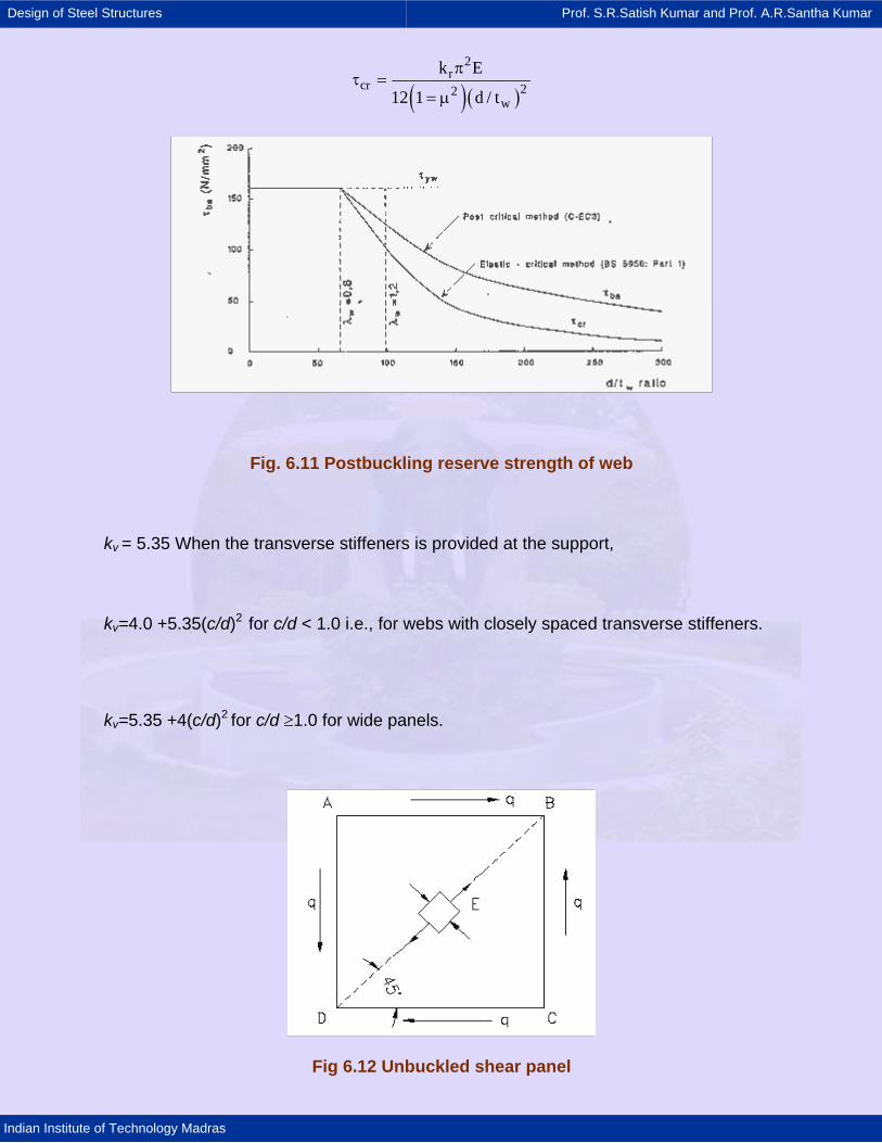
When a web plate is subjected to shear, we can visualize the structural
behaviour by considering the effect of complementary shear stresses generating
diagonal tension and diagonal compression. Consider an element E in equilibrium
inside a square web plate with shear stress q. The requirements of equilibrium result in
the generation of complementary shear stresses as shown in Fig.6.12. This result in the
element being subjected to principal compression along the direction AC and tension
along the direction BD. As the applied loading is incrementally enhanced, with
corresponding increases in q, very soon, the plate will buckle along the direction of
compression diagonal AC.
The plate will lose its capacity to any further increase in compressive stress. The
corresponding shear stress in the plate is the "critical shear stress" τcr. The value of τcr
can be determined from classical stability theory, if the boundary conditions of the plate
are known. As the true boundary conditions of the plate girder web are difficult to
establish due to restraints offered by flanges and stiffeners we may conservatively
assume them to be simply supported. The critical shear stress in such a case is given
by
Design of Steel Structures Prof. S.R.Satish Kumar and Prof. A.R.Santha Kumar
Indian Institute of Technology Madras
( )( )
2r
cr 22w
k E
12 1 d / t
πτ =
= µ
Fig. 6.11 Postbuckling reserve strength of web
kv = 5.35 When the transverse stiffeners is provided at the support,
kv=4.0 +5.35(c/d)2 for c/d < 1.0 i.e., for webs with closely spaced transverse stiffeners.
kv=5.35 +4(c/d)2 for c/d ≥1.0 for wide panels.
Fig 6.12 Unbuckled shear panel

Design of Steel Structures Prof. S.R.Satish Kumar and Prof. A.R.Santha Kumar
Indian Institute of Technology Madras
When the value of (d/t) is sufficiently low (d/t < 85) τcr increases above the value
of yield shear stress, and the web will yield under shear before buckling.
Based on this theory, the code gives the following values for τcr for webs, which are not
too slender (Section 8.4.2.2a). The values depend on the slenderness parameter λw as
defined in the code.
6.3.4.2.2. Tension field methods
Design of plate girders with intermediate stiffeners, as indicated in Fig. 6.10, can
be done by limiting their shear capacity to shear buckling strength. However, this
approach is uneconomical, as it does not account for the mobilisation of the additional
shear capacity as indicated earlier. The shear resistance is improved in the following
ways:
i. Increasing in buckling resistance due to reduced c/d ratio;
ii. The web develops tension field action and this resists considerably larger
stress than the elastic critical strength of web in shear
Figure 6.13 shows the diagonal tension fields anchored between top and bottom
flanges and against transverse stiffeners on either side of the panel with the stiffeners
acting as struts and the tension field acting as ties. The plate girder behaves similar to
an N-truss Fig.6.14.
The nominal shear strength for webs with intermediate stiffeners can be
calculated by this method according to the design provision given in code.
Fig 6.13 Tension field in individual sub-panel

Design of Steel Structures Prof. S.R.Satish Kumar and Prof. A.R.Santha Kumar
Indian Institute of Technology Madras
Fig 6.14 Tension field action and the equivalent N-truss
6.3.5 Stiffened web panels
For tension field action to develop in the end panels, adequate anchorage should be
provided all around the end panel. The anchor force Hq required to anchor the tension
field force is
1/ 2cr
q dpdp
VH 1.5V 1
V⎛ ⎞
= −⎜ ⎟⎜ ⎟⎝ ⎠
The end panel, when designed for tension field will impose additional loads on
end post; hence, it will become stout (Fig 8.2 of the code). For a simple design, it may
be assumed that the capacity of the end panel is restricted to Vcr, so that no tension
field develops in it (Fig 8.1 of the code). In this case, end panel acts as a beam
spanning between the flanges to resist shear and moment caused by Hq and produced
by tension field of penultimate panel.
This approach is conservative, as it does not utilise the post-buckling strength of
end panel especially where the shear is maximum. This will result in c/d value of the
end panel spacing to be less than of other panels. The end stiffeners should be
designed for compressive forces due to bearing and the moment Mtf, due to tension field
in the penultimate panel in order to be economical the end panel also may be designed
using tension field action. In this case, the bearing stiffeners and end post are designed

Design of Steel Structures Prof. S.R.Satish Kumar and Prof. A.R.Santha Kumar
Indian Institute of Technology Madras
for a combination due to bearing and a moment equal to 2/3 caused due to tension in
the flange Mtf, instead of one stout stiffener we can use a double stiffener as shown in
Fig. 8.3 of the code. Here, the end post is designed for horizontal shear and moment
Mtf.
6.3.6 Design of beams and plate girders with solid webs.
The high bending moment and shear forces caused by carrying heavy loads over
long spans may exceed the capacity of rolled beam sections. Plate girders can be used
in such cases and their proportions can be designed to achieve high strength/weight
ratio. In a plate girder, it can be assumed that the flanges resist the bending moment
and the web provides resistance to the shear force. For economic design, low flange
size and deep webs are provided. This results in webs for which shear failure mode is a
consequence of buckling rather than yielding.
Minimum web thickness − In general, we may have unstiffened web, a web
stiffened by transverse stiffeners, (Fig 6.9) or web stiffened by both transverse and
longitudinal stiffeners (Fig 6.10).
By choosing a minimum web thickness tw, the self-weight is reduced. However,
the webs are vulnerable to buckling and hence, stiffened if necessary. The web
thickness based on serviceability requirement is recommended in Section 8.6.1.1 of the
code.
6.3.6.1 Compression flange buckling requirement
Generally, the thickness of flange plate is not varied along the span of plate
girders. For non-composite plate girder the width of flange plates is chosen to be about
0.3 times the depth of the section as a thumb rule. It is also necessary to choose the
breadth to thickness ratio of the flange such that the section classification is generally
limited to plastic or compact section only. This is to avoid local buckling before reaching

Design of Steel Structures Prof. S.R.Satish Kumar and Prof. A.R.Santha Kumar
Indian Institute of Technology Madras
the yield stress. In order to avoid buckling of the compression flange into the web, the
web thickness shall be based on recommendation given in Section 8.6.1.2 of the code.
6.3.6.2 Flanges
For a plate girder subjected to external loading the minimum bending moment
occurs at one section usually, e.g. when the plate girder is simply supported at the ends
and subjected to the uniformly distributed load, then, maximum bending moment occurs
at the centre. Since the values of bending moment decreases towards the end, the
flange area designed to resist the maximum bending moment is not required to other
sections. Therefore the flange plate may be curtailed at a distance from the centre of
span greater than the distance where the plate is no longer required as the bending
moment decreases towards the ends.
Usually, two flange angles at the top and two flange angles at the bottom are
provided. These angles extend from one end to the other end of the girder. For a good
proportioning, the flange angles must provide an area at least one-third of the total
flange area.
Generally, horizontal flange plates are provided to and connected to the
outstanding legs of the flange angles. The flange plates provide an additional width to
the flange and thus, reduced the tendency of the compression flange to buckle. These
plates also contribute considerable moment of inertia for the section of the girder it gives
economy as regards the material and cost. At least one flange plate should be run for
the entire length of the girder
6.3.6.3 Flange splices
A joint in the flange element provided to increase the length of flange plates is
known as flange splice. The flange plate should be avoided as far as possible.
Generally, the flange plates can be obtained for full length of the plate girder. In spite of

Design of Steel Structures Prof. S.R.Satish Kumar and Prof. A.R.Santha Kumar
Indian Institute of Technology Madras
the availability of full length of flange plates, sometimes, it becomes necessary to make
flange splices. Flange joints should not be located at the points of main bending
moment. The design provisions for flange splices are given in detail in Section 8.6.3.2 of
the code.
6.3.6.3.1 Connection of flange to web
Rivets/bolts or weld connecting the flanges angles and the web will be subjected
to horizontal shear and sometimes vertical loads which may be applied directly to the
flanges for the different cases such as depending upon the directly applied load to the
either web or flange and with or without consideration of resistance of the web.
6.3.6.3.2 Splices in the web
A joint in the web plate provided to increase its length is known as web splices.
The plates are manufactured upto a limited length. When the maximum manufactured
length of the plate is insufficient for full length of the plate girder web splice becomes
essential, when the length of plate girder is too long to handle conveniently during
transportation and erection. Generally, web splices are not used in buildings; they are
mainly used in bridges.
Splices in the web of the plate girder are designed to resist the shear and
moment at the spliced section. The splice plates are provided on each side of the web.
Groove-welded splice in plate girders develop the full strength of the smaller spliced
section. Other types of splices in cross section of plate girders shall develop the
strength required by the forces at the point of the splice.

Design of Steel Structures Prof. S.R.Satish Kumar and Prof. A.R.Santha Kumar
Indian Institute of Technology Madras
6.3.7 Stiffener design
6.3.7.1 General
These are members provided to protect the web against buckling. The thin but
deep web plate is liable to vertical as well as diagonal buckling. The web may be
stiffened with vertical as well as longitudinal stiffeners
Stiffeners may be classified as
a) Intermediate transverse web stiffeners
b) Load carrying stiffeners
c) Bearing stiffeners
d) Torsion stiffeners
e) Diagonal stiffeners and
f) Tension stiffeners
The functions of the different types of stiffeners are explained in the Section 8.7.1.1 of
the code.
6.3.7.2 Stiff bearing length
The application of heavy concentrated loads to a girder will produce a region of
very high stresses in the part of the web directly under the load. One possible effect of
this is to cause outwards buckling of this region as if it were a vertical strut with its ends
restrained by the beam's flanges. This situation also exists at the supports where the
'load' is now the reaction and the problem is effectively turned upside down. It is usual
to interpose a plate between the point load and the beam flange, whereas in the case of
reactions acting through a flange, this normally implies the presence of a seating cleat.

Design of Steel Structures Prof. S.R.Satish Kumar and Prof. A.R.Santha Kumar
Indian Institute of Technology Madras
Fig 6.15 Dispersion of concentrated loads and reactions
In both cases, therefore, the load is actually spread out over a finite area by the
time it passes into the web as shown in Fig.6.15. It is controlled largely by the
dimensions of the plate used to transfer the load, which is itself termed "the stiff length
of bearing"
Outstand of web stiffeners and eccentricity of the stiffeners is explained as per
Section 8.7.1.2 to 8.7.1.5 of the code.
6.3.7.3 Design of Intermediate transverse web stiffeners
Intermediate transverse stiffeners are provided to prevent out of plane buckling of
web at the location of the stiffeners due to the combined effect of bending moment and
shear force.
Intermediate transverse stiffeners must be proportioned so as to satisfy two
conditions
1) They must be sufficiently stiff not to deform appreciably as the web tends to
buckle.
2) They must be sufficiently strong to withstand the shear transmitted by the
web.

Design of Steel Structures Prof. S.R.Satish Kumar and Prof. A.R.Santha Kumar
Indian Institute of Technology Madras
Since it is quite common to use the same stiffeners for more than one task (for
example, the stiffeners provided to increase shear buckling capacity can also be
carrying heavy point loads), the above conditions must also, in such cases, include the
effect of additional direct loading.
The condition (1) is covered by Section 8.7.2.4 of the code.
The strength requirement is checked by ensuring that the stiffeners acting as a
strut is capable of withstanding Fq. The buckling resistance Fq of the stiffeners acting as
strut (with a cruciform section as described earlier) should not be less than the
difference between the shear actually present adjacent to the stiffeners V, and the shear
capacity of the (unstiffened) web Vcr together with any coexisting reaction or moment.
Since the portion of the web immediately adjacent to the stiffeners tends to act with it,
this "strut" is assumed to consist also of a length of web of 20 t on either side of the
stiffeners centre line giving an effective section in the shape of a cruciform. Full details
of this strength check are given in Section 8.7.2.5 of the code. If tension field action is
being utilized, then the stiffeners bounding the end panel must also be capable of
accepting the additional forces associated with anchoring the tension field.
6.3.7.4 Load carrying stiffeners
Fig.6.16 Cruciform section of the load carrying stiffener

Design of Steel Structures Prof. S.R.Satish Kumar and Prof. A.R.Santha Kumar
Indian Institute of Technology Madras
Whenever there is a risk of the buckling resistance of the web being exceeded,
especially owing to concentrated loads, load-carrying stiffeners are provided. The
design of load-carrying stiffeners is essentially the same as the design of vertical
stiffeners. The load is again assumed to be resisted by strut comprising of the actual
stiffeners plus a length of web of 20t on either side, giving an effective cruciform section.
Providing the loaded flange is laterally restrained, the effective length of the 'strut' may
be taken as 0.7L. Although no separate stiffener check is necessary, a load-bearing
stiffener must be of sufficient size that if the full load were to be applied to them acting
independently, i.e., on a cross-section consisting of just the stiffeners, as per Fig 6.16.
Then the stress induced should not exceed the design strength by more than 25%. The
bearing stress in the stiffeners is checked using the area of that portion of the stiffeners
in contact with the flange through which compressive force is transmitted.
6.3.7.5 Bearing stiffeners
Bearing stiffeners are required whenever concentrated loads, which could cause
vertical buckling of web of the girder, are applied to either flange. Such situations occur
on the bottom flange at the reactions and on the top flange at the point of concentrated
loads. Figure 6.17 shows bearing stiffeners consisting of plates welded to the web. They
must fit tightly against the loaded flange. There must be sufficient area of contact
between the stiffeners and the flange to deliver; the load without exceeding the
permissible bearing on either the flange material or the stiffeners must be adequate
against buckling and the connection to the web must be sufficient to transmit the load as
per Section 8.7.4 of the code.
Fig. 6.17 Bearing stiffeners

Design of Steel Structures Prof. S.R.Satish Kumar and Prof. A.R.Santha Kumar
Indian Institute of Technology Madras
The bearing stress on the contact area between stiffeners and flanges is
analogous to the compressive stress at the junction of web and flange of rolled beams
subjected to concentrated load.
Since buckling of bearing stiffeners is analogous to buckling of web at point of
concentrated load, the required moment of inertia is not easy to evaluate. The buckled
stiffeners may take any forms depending on the manner in which the flanges are
restrained. In most cases, the compression flange of the girder will be supported
laterally at points of concentrated load by bracing or by beams framing into it, so
buckling will approximate the form of an end-fixed column. Even if the flanges are free
to rotate, the stiffeners need not be considered as end-hinged columns, because the
load concentrated on one end of the stiffeners is resisted by forces distributed along its
connection to the web instead of by a force concentrated at the opposite end as in
columns.
The connection to the web is merely a matter of providing sufficient welding to
transmit the calculated load on the stiffeners as per the Section 8.7.6 of the code.
Design of different types of stiffeners is given in the code from Sections 8.7.4 to
8.7.9.
6.3.7.6 Connection of web of load carrying and bearing
The web connection of load carrying stiffeners to resist the external load and
reactions through flange shall be designed as per the design criteria given in the code.
6.3.7.7 Horizontal stiffeners
Horizontal stiffeners are generally not provided individually. They are used in
addition to vertical stiffeners, which are provided close to the support to increase the
bearing resistance and to improve the shear capacity.

Design of Steel Structures Prof. S.R.Satish Kumar and Prof. A.R.Santha Kumar
Indian Institute of Technology Madras
The location and placing of horizontal stiffeners on the web are based on the
location of neutral axis of the girder. Thickness of the web tw and second moment of
area of the stiffeners Is are as per the conditions and design provisions given in Section
8.7.13 of the code.
6.3.8 Box girders
The design and detailing of box girders shall be such as to give full advantage of
its higher load carrying capacity.
Diaphragm shall be used where external vertical as well as transverse forces are
to be transmitted from one member to another. The diaphragms and their fastenings
shall be proportioned to distribute other force applied to them and in addition, to resist
the design transverse force and the resulting shear forces. The design transverse force
shall be taken as shared equally between the diaphragms.
When concentrated loads are carried from one beam to the other or distributed
between the beams, diaphragms having sufficient stiffeners to distribute the load shall
be bolted or welded between the beams. The design of members shall provide for
torsion resulting from any unequal distribution of loads.
6.3.9 Purlin and sheeting rails
Purlins attached to the compression flange of a main member would normally be
acceptable as providing full torsional restraint; where purlins are attached to tension
flange, they should be capable of providing positional restraint to that flange but are
unlikely (due to the rather light purlin/rafter connections normally employed) to be
capable of preventing twist and bending moment based on the lateral instability of the
compression flange.

Design of Steel Structures Prof. S.R.Satish Kumar and Prof. A.R.Santha Kumar
Indian Institute of Technology Madras
6.3.10 Bending in a non-principal plane
When deflections are constrained to a non-principal plane by the presence of
lateral restraints, the principal axes bending moments are calculated due to the restraint
forces as well as the applied forcs by any rational method. The combined effect is
verified using the provisions in Section 9. Similarly, when the deflections are
unconstrained due to loads acting in a non-principal plane, the principal axes bending
moments are arrived by any rational method. The combined effects have to satisfy the
requirements of Section 9.

Design of Steel Structures Prof. S.R.Satish Kumar and Prof. A.R.Santha Kumar
Indian Institute of Technology Madras
6.4 Summary
Rolled beams and plate girders are important structural members. In this
presentation, the limit state method of design of beams as per the IS: 800
revisions have been explained. Laterally supported and unsupported beams
have been considered. The phenomenon of lateral torsional buckling has been
explained. Shear yielding and shear buckling have been treated. Design of
various types of stiffeners for plate girders is explained.

Design of Steel Structures Prof. S.R.Satish Kumar and Prof. A.R.Santha Kumar
Indian Institute of Technology Madras
6.5 References
1. David A. Nethercot (2001), Limit states design of structural steelwork,
Spon Press, London
2. IS: 800-(2003): Draft Structural Steel Code
3. Teaching Resource for Structural Steel design (2001), INSDAG
Publication.
4. Narayanan R., Lawless V, Naji F.J. and Taylor J.C., (1993), Introduction to
Concise Eurocde3 (C-EC3)-with worked examples, The Steel
Construction Institute.

Design of Steel Structures Prof. S.R.Satish Kumar and Prof. A.R.Santha Kumar
Indian Institute of Technology Madras
Problem 1
Design a hand operated overhead crane, which is provided in a shed, whose
details are:
Capacity of crane = 50 kN
Longitudinal spacing of column = 6m
Center to center distance of gantry girder = 12m
Wheel spacing = 3m
Edge distance = 1m
Weight of crane girder = 40 kN
Weight of trolley car = 10 kN
Design by allowable stress method as per IS: 800 - 1984
To find wheel load (refer fig.1):

Design of Steel Structures Prof. S.R.Satish Kumar and Prof. A.R.Santha Kumar
Indian Institute of Technology Madras
RA = 20 + 60 (11 / 12) = 75 kN
Wheel load = RA / 2 = 37.5 kN
To find maximum BM in gantry girder (refer fig.2):
RA = 46.88 kN
RB = 28.12 kN
Max. BM = 28.12 x 2.25 = 63.27 kN-m
Adding 10% for impact,
M1 = 1.1 x 63.27 = 69.60 kN-m
Max. BM due to self - weight of girder and rail taking total weight as 1.2 kN/m
Therefore Total BM, M = 75 kN-m
To find maximum shear force (refer fig.3):
SF = RA = 59.85 kN.
To find lateral loads:
This is given by 2.5% of (lateral load / number of wheel = 0.025 x 60 / 2 kN = 0.75 kN
Therefore Max BM due to lateral load by proportion is given by, ML = (63.27 / 37.5) x 0.75 = 1.27 kN-m
Design of section
Approximate section modulus Zc required, (M / σ bc) = 75 x 106 / 119 = 636 x 103mm3 [for λ = 120, D / T = 25].
Since, the beam is subjected to lateral loads also, higher section is selected.
For, ISMB 450 @ 710.2 N/m,
Zx = 1350.7 cm3 , T = 17.3 mm,

Design of Steel Structures Prof. S.R.Satish Kumar and Prof. A.R.Santha Kumar
Indian Institute of Technology Madras
t = 9.4mm, Iyy = 111.2cm3
ry = 30.1mm,
bf = 150mm
To find allowable stresses,
T/t = 17.4 / 9.4 = 1.85 < 2
D/T = 450 / 17.4 = 25.86 ~ 26
L/ry = 6000 / 30.1 = 199.3 ~ 200
Therefore allowable bending compression about major axis is, sbc' x = 77.6
N/mm2
Actual stress in compression side, sb' x = M / Z = 55.5 N / mm2.
The bending moment about Y-axis is transmitted only to the top of flange
and the flange is treated as rectangular section. The allowable stress is sbc. y =
165 MPa (i.e. 0.66 fy).
Zy of the flange = 111.2 / 2 = 55.6 cm3
Therefore sby = My / Zy = 1.27 x 10⁶ / 55.6 x 103
= 22.84 MPa
The admissible design criteria is = (sbx / sbcx) + ( sby / sbcy) = (55.5 / 77.6) +
(22.84 / 165) = 0.715 + 0.138 = 0.854 < 1. Hence , the design is safe. So, ISMB
450 is suitable
Check for shear:
Design shear stress, τx V / (Dt) = 59.85 x 10³ / 450 x 9.4 = 14.15 MPa. This is
less than τa (0.4fy). Hence, the design is o.k.
Check for deflection and longitudinal bending can be done as usual.

Design of Steel Structures Prof. S.R.Satish Kumar and Prof. A.R.Santha Kumar
Indian Institute of Technology Madras
Design by limit state method as per IS: 800 draft code
For ISMB 450, properties are given below:
T = 17.4mm, t = 9.4mm, b = 150mm, ry = 30.1mm, Zp = 1533.33 cm3, Zc =
1350.7 cm3, Shape factor = 1.15, Izz = 30390.8 cm4, H1 = d = 379.2mm
Section classification:
Flange criteria: b / T = 75 / 17.4 = 4.31 < 9.4
No local buckling. Therefore OK
Web criteria: d / tw = 379.2 / 9.4
= 40.34 < 83.9
No local buckling. Therefore OK
Section plastic.
Shear capacity:
Fv / Fvd = (59.85 x 1.5) / 555 = 0.1634 < 0.6
Check for torsional buckling (CI.8.2.2):
tf / tw <= 17.4 / 9.4 = 1.85 < 2.
Therefore βLT = 1.2 for plastic section
Mcr = Elastic critical moment

Design of Steel Structures Prof. S.R.Satish Kumar and Prof. A.R.Santha Kumar
Indian Institute of Technology Madras
(βb = 1 for plastic section)
Therefore φLT = 0.5 [1 + αLT (λLT - 0.2) + λ2LT
= 0.5 [1 + 0.21 (1.248 - 0.2) + 1.2482]
= 1.389
Therefore Md = βb. zp. fbd
= 1 x 1533.3 x 103 x 113.7
= 1.7434 x 108 = 174.34 kN-m
Factored longitudinal moment, Mf = 75 x 1.5 = 112.5 kN-m
Factored lateral moment, MfL = 1.27 x 1.5 = 1.91 kN-m

Design of Steel Structures Prof. S.R.Satish Kumar and Prof. A.R.Santha Kumar
Indian Institute of Technology Madras
Lateral BM capacity = MdL
= (112.5 / 135.9) + (1.91 / 14.53) = 0.96 < 1
Hence, it is safe
Problem 2:
Design a member (beam - column) of length 5.0M subjected to direct load 6.0T
(DL) and 5.0T (LL) and bending moments of Mzz {3.6TM (DL) + 2.5TM (LL)} and Myy
{0.55TM (DL) + 0.34TM (LL)} at top and Mzz {5.0TM (DL) + 3.4TM (LL)} and Myy
{0.6TM (DL) + 0.36TM (LL)} at bottom.
LSM {Section 9.0 of draft IS: 800 (LSM version)}
Factored Load,
N = 6.0 x 1.50 + 5.0 x 1.5 = 16.5T (Refer Table 5.1 for load factors)
Factored Moments:
At top, Mz = 9.15TM, My = 1.335TM
At bottom, Mz = 12.60TM, My = -1.44TM
Section used = MB500.
For MB500:

Design of Steel Structures Prof. S.R.Satish Kumar and Prof. A.R.Santha Kumar
Indian Institute of Technology Madras
A = 110.7 cm2; ryy = 3.52 cm,
Izz = 48161.0 cm4; Zzz = 1809 cm3
Z yy = 152.2 cm3; Zpz = 2074.7 m3;
Zpy = 302.9 cm3
d = 465.6 mm, tw = 10.29 mm
rzz = 20.21 cm, b = 180 mm;
Iyy = 1369.8 cm3
(i) Sectional Classifications (Refer Fig: 3.1 and Table - 3.1 of draft code):
b / tf = 90 / 17.2 = 5.23 < 8.92, therefore the section is plastic.
d / tw = 465.6 / 10.2 = 45.65 < 47, therefore the section is semi-compact for
direct load and plastic for bending moment.
(ii) Check for resistance of the section against material failure due to the
combined effects of the loading (Clause-9.3.1):
Nd = Axial strength = A. fy /γmo
= 110.7 x 2500 / 1.10 x 10-3 = 251.68T
N = 16.5T
n = N / Nd = 16.5 / 251.68 = 0.066 < 0.2
Therefore Mndz = 1.1Mdz (1-n) < Mdz
Therefore Mndz = 1.1{1.0 * 2074.7 * 2500 / 1.10} (1 - 0.066) * 10-5 < Mdz
Therefore Mndz = 48.44T-m > Mdz (=47.15T-m )
Therefore Mndz = Mdz = 47.15T-m
For, n<= 0.2 Mndy = Mdy
Mndy = (1.0 x 302.9 x 2500) / (1.10 x 100000) = 6.88T-m
(βb = 1.0 for calculation of Mdz and Mdy as per clause 8.2.1.2)

Design of Steel Structures Prof. S.R.Satish Kumar and Prof. A.R.Santha Kumar
Indian Institute of Technology Madras
Therefore (My / Mndy)α1 + (Mz / Mndz)α2 = (1.44 / 6.88)1 + (12.60 / 47.15)2 = 0.281 <= 1.0
{α1 = 5n but >= 1, therefore α1 = 5 x 0.066 = 0.33 = 1
α2 = 2 (As per Table 9.1)}
Alternatively,
(N / Nd ) + (Mz / Mdz) + (My / Mdy) = { (16.5 x 103 x 1.10) / (110.7 x 2500) + (12.60 x 105 x 1.10) / (302.9 x 2500) = 0.54 <= 1.0
(iii) Check for resistance of the member for combined effects of buckling (Clause- 9.3.2):
(a) Determination Pdz, Pdy and Pd (Clause 7.12)
KLy = KLz = 0.85 x 500 = 425mm
( KLz / rz) = 425 / 20.21 = 21.03
( KLy / ry) = 425 / 3.52 = 120.7
Therefore, non- dimensional slenderness ratios, λz = 0.237 and λy = 1.359.
For major axis buckling curve 'a' is applicable (Refer Table 7.2).
From Table 7.4a,
fcdz = 225.4 MPa
Pdz = 225.4 x 10 x 110.7 x 10-3 = 249.65T
For minor axis buckling curve 'b' is applied (Refer Table 7.2)
From Table 7.4b,
fcdy = 90.80 MPa
Pdy = 90.80 x 10 x 110.7 x 10-3 = 100.60T
Therefore, Pd = Pdy = 100.60T
(b) Determination of Mdz (Clause 9.3.2.2 and Clause 8.2.2).

Design of Steel Structures Prof. S.R.Satish Kumar and Prof. A.R.Santha Kumar
Indian Institute of Technology Madras
Elastic critical moment is given by (clause 8.2.21).
Mcr = [(βLT π2EIyh) / {2(KL)2}] [1 + 1/20 {(KL / ry) / (h / tf)}2]0.5
=[(1.20 x π2 x 2 x 105 x 1369.8 x 104 x 500) / (2 x 42502)] [1 + 1/20
{(120.70) / (500 / 17.2)}2]0.5
= 6.129 x 10⁸ N-mm
(c) Determination of Mdy (Clause 9.3.2.2)
Mdy = βb Zpy. fy / γm
= 1.0 x 302.90 x 2500 / 1.1 x 10-5 = 6.88T-m
(d) Determination of Cz (Clause 9.3.2.2) From Table - 9.2,

Design of Steel Structures Prof. S.R.Satish Kumar and Prof. A.R.Santha Kumar
Indian Institute of Technology Madras
= 0.237 (2 x 1.292 - 4) + 0.1469
= -0.188
For torsional buckling,
(e) Determination of Cy (Clause 9.3.2.2)
Therefore, section is safe. Interaction value is less in LSM than WSM.

Design of Steel Structures Prof. S.R.Satish Kumar and Prof. A.R.Santha Kumar
Indian Institute of Technology Madras
Design of typical beam
Example-1
The beam (ISMB 400) in Fig.1 is designed considering it is fully restrained laterally.
1. WSM (clause 6.2 of IS:800 - 1984):
Bending moment, M=18.75Tm For ISMB 450, Z=1350.7 cm3 Therefore
s bc(cal) = 18.75 *105 / 1350.7
= 1388.17 kg /cm2 < 1650 Kg/cm2
Therefore percentage strength attained is 0.8413 or 84.13%s
2. LSM (clause 8.2 of draft IS:800):
Factored load = 1.5 * 2.0 + 1.5 * 4.0 = 9.0T
Factored bending moment = 9.0 * 5.02 / 8
= 28.125Tm
Factored shear force = 22.50T = Fv
Fig.1

Design of Steel Structures Prof. S.R.Satish Kumar and Prof. A.R.Santha Kumar
Indian Institute of Technology Madras
For, ISMB450,
D = 450 mm B = 150 mm
tw = 9.4 mm T=17.4 mm
Ixx = 30390.8 cm4 Iyy = 834.0 cm
ryy = 3.01 cm h1 = 379.2 cm = d
i ) Refering Table 3.1 of the code for section classification, we get :
Flange criterion = ( B / 2 ) / T = ( 150 / 2 ) /17.4
= 4.31 < 9.4.
Web criteria = d / tw = 379.2 / 9.4
= 40.34 < 83.9.
Therefore, section is plastic.
ii ) Shear capacity ( refer clause 8.4 of draft code ) :
Fvd = ( fyw .Av )/ ( gmo ) = ( fyw .htw )/( gmo )
= ( 2500 * 45.0 * 0.94 )/ ( * 1.10 * 1000 )
= 55.50T
Fv / Fvd = 22.50 /55.5 = 0.405 < 0.6.
Therefore , shear force does not govern permissible moment capacity ( refer
clause 8.2.1.2 of the draft code ).
iii ) Since the section is ' plastic' ,
Md = ( Zp .fy ) / gmo
where , Zp = Plastic Modulus = 1533.36 cm3
(refer Appendix-I of draft code).
Therefore , Md = ( 1533.36*2500 ) /1.10 * 105
= 34.85Tm
Percentage strength attained for LSM is (28.125 / 34.85 ) = 0.807 or 80.7 %
which is less than 84.3 % in the case of WSM .

Design of Steel Structures Prof. S.R.Satish Kumar and Prof. A.R.Santha Kumar
Indian Institute of Technology Madras
iv ) Now , let us check for web buckling :
Kv = 5.35 (for transverse stiffeners only at supports as per clause 8.4.2.2 of draft code ).
The elastic critical shear stress of the web is given by :
τcr.e = ( kv .π2 .E ) / { 12 ( 1 - µ2 )( d / tw )2 }
= ( 5.35 π2 E ) / { 12 ( 1 - 0.32 )( 379.2 / 9.4 )2 }
= 594.264 N / mm2 .
Now as per clause 8.4.2.2 of draft code ,
λw = { fyw / ( τcr.e )}0.5
= {250 / ( * 594.264 )}0.5 = 0.4928 < 0.8 .
where , λw is a non-dimensional web slenderness ratio for shear buckling for stress varying from greater than 0.8 to less than 1.25 .
Therefore , τb ( shear stress corresponding to buckling ) is given as :
τb = fyw / = 250 / = 144.34 N / mm2 .
Vd = d.tw. τb / γmo
= 37.92 * 0.94 * 1443.34 * 10-3 / 1.10
= 46.77Ts
As VD > Fv ( = 22.5T ), the section is safe in shear.
For checking of deflection :
s = (5 * 60 * 5004 ) / ( 384 * 2.1 * 106 * 30390.8 )
= 0.76 cm = 7.6 mm = L / 658
Hence O.K.

Design of Steel Structures Prof. S.R.Satish Kumar and Prof. A.R.Santha Kumar
Indian Institute of Technology Madras
Example - 2
The beam ( ISMB 500 ) shown in Fig2 is carrying point load as shown , is to be designed. The beam is considered to be restrained laterally.
1 . In WSM ( clause 6.2 of IS : 800 - 1984 ) :
Bending Moment , M = (5 + 20 ) * 3 / 4
= 26.25Tm
For, ISMB 500 : Z = 1808.7 cm3
Fig .2
So , σbc(cal) = 26.25 * 105 / 1808.7 Kg / cm2
= 1451.318 Kg / m2 .
Therefore , percentage strength attained is 0.88 or 88 %.
2 . In LSM (clause 8.2 of draft IS : 800):
Factored load = 1.5 * 15 + 1.5 * 20 = 52.50T
Therefore,
Factored bending moment = 52.5 * 3.0 / 4
= 39.375Tm
Factored shear force, Fv = 52.50 / 2 = 26.25T
i ) For ,section classification of this ISMB500 , ( refer table 3.1 of the code ) , we get :

Design of Steel Structures Prof. S.R.Satish Kumar and Prof. A.R.Santha Kumar
Indian Institute of Technology Madras
D = 500 mm d = 424.1 mm
r1 = 17mm ry = 3.52 cm
Zp = 20.25.74 cm3 T = 17.2 mm
b = 180 mm tw = 10.2 mm .
Flange criterion , (b / 2) / T = ( 180 / 2 ) / 17.2
= 5.23 < 9.4
Web criterion , d / tw = 424.1 /10.2
= 41.57 < 83.9 ( O.K )
Therefore the section is plastic.
ii ) Shear capacity ( clause 8.4 ):
Fvd = ( fyw .Av )/ ( γmo )
= ( 2500 * 50 * 1.02 )/ ( * 1.10 * 1000 )
= 66.92T
Fv = 26.25T
Since Fv / Fvd < 0.6. shear force does not govern Bending Strength
iii ) For moment check :
Since the section is plastic ,
Md = ( Zp .fy ) / γmo
= ( 2025.74 * 2500 ) /1.10 * 105
= 46.04Tm
Therefore , Percentage strength attained is ( 39.375 / 46.04 ) = 0.855 or 85.5 % which is less than 88 % in case of WSM
iv ) Check for web buckling :

Design of Steel Structures Prof. S.R.Satish Kumar and Prof. A.R.Santha Kumar
Indian Institute of Technology Madras
Kv = 5.35 (for transverse stiffeners only at supports as per clause 8.4.2.2 of draft code ).
τcr.e = ( kv .π2 .E ) / { 12 ( 1 - µ2 )( d / tw )2 }
= ( 5.35 π2 E ) / { 12 ( 1 - 0.32 )( 424.1 / 10.2 )2 }
= 559.40 N / mm2 .
Now as per clause 8.4.2.2 ,
λw = { fyw / ( τcr.e )}0.5
= {250 / ( * 559.40 )}0.5 = 0.508 < 0.8 .
Therefore ,
τb = fyw / = 250 / = 144.34 N / mm2 .
VD = d.tw. τb / γmo
= 42.41 * 1.02 * 1443.4 * 10-3 / 1.10
= 56.76T
Since VD > Fv ( = 26.25T ), the section is safe against shear.
For checking of deflection :
σ = ( 35000 * 3003 ) / ( 48 * 2.1 * 106 * 45218.3 )
= 0.207 cm = 2.07 mm = L / 1446
Hence O.K.

Design of Steel Structures Prof. S.R.Satish Kumar and Prof. A.R.Santha Kumar
Indian Institute of Technology Madras
Example - 3
The beam , ISMB500 as shown in Fig.3 is to be designed considering no restraint along the span against lateral buckling .
i ) In WSM (clause 6.2, 6.2.2, 6.2.3 and 6.2.4 and 6.2.4.1 of IS : 800 - 1984 ) :
Bending moment, M = 2.1 * 62 / 8 = 9.45Tm
For, ISMB500 :
L = 600 cm ry = 3.52 cm
T = 17.2 mm Z = 1808.7 cm3
Fig.3
Therefore,
Y = 26.5 * 105 / ( 600 / 3.52 )2 = 91.2
X = 91.21 [ 1 + ( 1 / 20 ){( 600 * 1.72 ) / (3.52 * 50 )}2]
= 150.40
and fcb = k1 ( X + k2y ) C2 / C1 = X
(since C2 = C1 , k1 = 1 and k2 = 0 )
Now ,
σbc(perm) = (0.66 fcb.fy ) / {fcbn + fyn}1/n
= 746 Kg / cm2.

Design of Steel Structures Prof. S.R.Satish Kumar and Prof. A.R.Santha Kumar
Indian Institute of Technology Madras
and σbc(cal) = 9.45 * 105 / 1808.7
= 522.5 Kg / cm2.
Therefore , percentage strength attained is ( 522.5 / 746 ) = 0.7 or 70 %.
ii ) In LSM (clause 8.2 of draft IS : 800 ) :
For MB 500 :
D = 500 mm T = 17.2 mm
B = 180 mm t = 10.2 mm
Zp = 2025.74 cm3 ryy = 3.52 cm
H1 = d = 424.1 mm
Izz = 45218.3 cm4 , Iyy = 1369.8 cm4
iii) Classification of section ( ref . Table 3.1 of the code ):
b / T = 90 / 17.2 = 5.2 < 9.4 , hence O.K.
d / t = 424.1 / 10.2 = 41.6 < 83.90 ( O.K)
Therefore , the section is Plastic .
iv ) Check for torsional buckling ( clause 8.2.2 ) :
tf / tw for ISMB 500 = 17.2 / 10.2 = 1.69 2.0
Therefore , βLT = 1.20 ,for plastic and compact aestions.
Mcr = Elastic critical moment given as :
Mcr = { ( βLT π2 .EIy ) / (KL)2 }[ 1 + ( 1 / 20 ) {KL / ry ) / ( h / tf ) }2 ]0.5 ( h/ 2 )
( ref . clause 8.2.2.1 )
= (1.20 π2 * 2 * 106 * 1369.8 / 6002 )[ 1 + ( / 20 ){ (600 / 3.52) / (50 /
1.72)}2 ]0.5 (50 / 2)
= 371556.3 Kg-cm .
Now , λLT = ( βb .Zp .fy / Mcr ) = 1.1675
( since βb = 1.0 for plastic and compact sections )
Therefore ,

Design of Steel Structures Prof. S.R.Satish Kumar and Prof. A.R.Santha Kumar
Indian Institute of Technology Madras
φLT = 0.5 [ 1 + αLT ( λLT - 0.2 ) + λLT2 ]
= 0.5 [ 1 + 0.2 ( 1.1675 - 0.2 ) + 1.16752 ]
= 1.283 ( αLT = 0.21 for rolled section ).
Therefore XLT = 1 / [ φLT + { φLT2 - λLT
2 }0.5 ]
= 1 / [ 1.283 + { 1.2832 - 1.16752 }0.5 ]
= 0.55
Md = 1.0 * 0.55 * 2025.74 * 2500 / 1.10 * 10-5
= 25.32Tm
Now actual moment is obtained as follows:
Factored load = 1.0 * 1.5 + 1.1 * 1.5 = 3.15Tm
Factored moment = 14.175Tm < Md
Percentage strength attained is (14.75 / 25.32 ) = 0.56 or 56 % which is less
than 70 % in case of WSM.
Hence , the beam is safe both in LSM and WSM design but percentage
strength attained is comparatively less in LSM for the same section
Problem:
The girder showed in Fig. E1 is fuly restrained against lateral buckling throughtout its sapan. The span is 36 m and carries two concentrated loads as show in Fig. E1. Design a plate girder.
Yield stress of steel, fy = 250 N/mm2
Material factor for steel,γm = 1.15
Dead Load factor,γfd = 1.50
Imposed load factor,γfl = 1.50

Design of Steel Structures Prof. S.R.Satish Kumar and Prof. A.R.Santha Kumar
Indian Institute of Technology Madras
1.0 Loading
Dead load:
Uniformly distributed load, wd = 18 kN/m
Concentrated load, W1d = 180 KN
Concentrated load, W2d = 180 KN
Live load:
Uniformly distributed load, W = 35 kN/m
Concentrated load, W1l = 400 kN
Concentrated load, W2l = 400 kN
Factored Loads
w' = wd * γfd + wl * γfl = 18 * 1.5 + 35 * 1.5 = 79.5 kN/m
W'1 = W1d * γfd + W1l * γfl = 180 * 1.5 + 400 * 1.5 = 870 kN
W'2 = W2d * γfd + W2l * γfl = 180 * 1.5 + 400 * 1.5 = 870 kN

Design of Steel Structures Prof. S.R.Satish Kumar and Prof. A.R.Santha Kumar
Indian Institute of Technology Madras
2.0 Bending moment and shear force
Bending moment (kN-m) Shear force (kN)
UDL effect
Concentrated load effect
w=870
Total 20709 2301
The desigh shear forces and bending moments are shown inf Fig. E2.
3.0 Initial sizing of plate girder
Depth of the plate girder:
The recommended span/depth ratio for simply supported girder varies
between 12 for short span and wo for long span girder. Let us consider depth of
the girder as 2600 mm.
Depth of 2600 mm is acceptable.
(For drawing the bending moment and shear force diagrams, factored
loads are considered)

Design of Steel Structures Prof. S.R.Satish Kumar and Prof. A.R.Santha Kumar
Indian Institute of Technology Madras
Fig.E2 Bending moment and shear force diagrams
Flange:
Py = 250/1.15 = 217.4 N/mm 2
Single flange area,
By thumb rule, the flange width is assumed as 0.3 times the depth of the section.
Try 780 X 50 mm, giving an area = 39000 mm2.

Design of Steel Structures Prof. S.R.Satish Kumar and Prof. A.R.Santha Kumar
Indian Institute of Technology Madras
Web:
Minimum web thickness for plate girder in builidings usually varies between 10
mm to 20 mm. Here, thickness is assumed as 16mm.
Hence, web size is 2600 X 16 mm
4.0 Section classification
Flange:
Hence, Flange is COMPACT SECTION.
Web:
Hence, the web is checked for shear buckling.
5.0 Checks
Check for serviceability:
Web is adequate for serviceability.

Design of Steel Structures Prof. S.R.Satish Kumar and Prof. A.R.Santha Kumar
Indian Institute of Technology Madras
Check for flange buckling in to web:
Assuming stiffener spacing, a > 1.5 d
Since, t (=16 mm) > 8.2 mm, the web is adequate to avoid flange buckling
into the web.
Check for moment carrying capacity of the flanges:
The moment is assumed to be resisted by flanges alone and the web
resists shear only.
Distance between centroid fo flanges, hs = d + T = 2600 + 50 = 2650 mm
Af = B * T = 780 * 50 = 39000 mm2
Mc = Pyf * Af * hs = 217.4 * 39000 * 2650 * 10-6 = 222468.3 kN-m
> 20709 kN-m
Hence, the section in adequate for carrying moment and web is designed
for shear.
6.0 Web design
The stiffeners are spaced as shown in Fig.E5. Three different spacing
values 2500, 3250 and 3600 mm are adopted for trail as shown in fig. E5.
End panel (AB) design:
d=2600 mm
t = 16 mm
Maximum shear stress in the panel is

Design of Steel Structures Prof. S.R.Satish Kumar and Prof. A.R.Santha Kumar
Indian Institute of Technology Madras
Calcualtion of critical stress,
Slenderness parameter,
Hence, Critical shear strength (qcr = qe) = 69.5 N/mm2
Since, fv < qcr (55.3 < 69.5)
Tension field action need not be utilised for design.
Checks for the end panel AB:
End panel AB should also be checked as a beam (Spanning between the
flanges of the girder) capable of resisting a shear force Rtf and a moment Mtfdue
to anochor forces.
(In the following calculations boundary stiffeners are omitted for simplicity)

Design of Steel Structures Prof. S.R.Satish Kumar and Prof. A.R.Santha Kumar
Indian Institute of Technology Madras
Check for shear capacity of the end panel:
Check for moment capacity of end panel AB:
The end panel can carry the bending moment.
Design of panel BC:
Panel BC will be designed using tension field action
d = 2600 mm ; t = 16 mm

Design of Steel Structures Prof. S.R.Satish Kumar and Prof. A.R.Santha Kumar
Indian Institute of Technology Madras
Calculation of basic shear strength, qb:
Panel BC is safe against shear buckling.

Design of Steel Structures Prof. S.R.Satish Kumar and Prof. A.R.Santha Kumar
Indian Institute of Technology Madras
7.0 Design of stiffeners
Load bearing stiffener at A:
Design should be made for compression force due to bearing and moment.
Design force due to bearing, Fb = 2301 kN
Force (Fm) due to moment Mtf, is
Total compression = Fc = Fb + Fm = 2301 + 482 = 2783 kN
Area of Stiffener in contact with the flange, A:
Area (A) should be greater than
Try stiffener of 2 flats of size 270 x 25 mm thick
Allow 15 mm to cope for web/flange weld
A = 255 * 25 * 2 = 12750 mm2 > 10241 mm2
Bearing check is ok.
Check for outstand:
Outstand from face of web should not be greater than

Design of Steel Structures Prof. S.R.Satish Kumar and Prof. A.R.Santha Kumar
Indian Institute of Technology Madras
Hence, outstand criteria is satisfied.
Check stiffener for buckling:
The effective stiffener section is shown in Fig. E3
The buckling resistance due to web is neglected here for the sake of simplicity.
Flange is restrained against rotation in the plane of stiffener, then
Ie = 0.71 = 0.7 * 2600 = 1820

Design of Steel Structures Prof. S.R.Satish Kumar and Prof. A.R.Santha Kumar
Indian Institute of Technology Madras
from table(30 of chapter on axially compressed columns
Buckling resistance of stiffener is
Therefore, stiffener provided is safe against buckling.
Check stiffener A as a bearing stiffener:
Local capacity of the web:
Assume, stiff bearing length b1=0
n2 = 2.5 * 50 * 2 = 250 BS 5950 : Part -1, Clause 4.5.3
Pcrip = (b1 + n2) tPyw
= (0 + 250) * 16 * (250/1.15) * 10-3 = 870 kN
Bearing stiffener is designed for FA
FA = Fx = Pcrip = 2783 - 870 = 1931 kN
Bearning capacity of stiffener alone
PA = Pys * A = (50/1.15) * 13500/1000 = 2935 kN
Since, FA < PA (1931 < 2935)
The designed stiffener is OK in bearing.
Stiffener A - Adopt 2 flats 270 mm X 25 mm thick

Design of Steel Structures Prof. S.R.Satish Kumar and Prof. A.R.Santha Kumar
Indian Institute of Technology Madras
Design of intermediate stiffener at B:
Stiffener at B is the most critical one and will be chosen for the design.
Minimum Stiffness
Conservatively ' t ' is taken as actual web thickness and minimum ' a ' is used.
Try intermediate stiffener of 2 flats 120 mm X 14 mm
Check for outstand:
Outstand = 120 mm (120 < 192)
Hence, outstand criteria is satisfied.
Buckling check:
Stiffener force, Fq = V - Vs
Where V = Total shear force
Vs = Vcr of the web
a / d = 3600 / 2600 = 1.38

Design of Steel Structures Prof. S.R.Satish Kumar and Prof. A.R.Santha Kumar
Indian Institute of Technology Madras
d / t = 2600 / 16 = 162.5
Hence, Critical shear strength = 52.8 N/mm2 (qcr = qe)
Vcr = qcrdt = 52.8 * 2600 * 16 * 10-3 = 2196 kN
Buckling resistance of intermediate stiffener at B:

Design of Steel Structures Prof. S.R.Satish Kumar and Prof. A.R.Santha Kumar
Indian Institute of Technology Madras
From table3 of chapter on axially compressed columns,
Buckling resistance = (213.2/1.15) * 13600 * 10-3 = 2521 kN
Shear force at B, VB = 2301-{(2301 - 1585.5)*(2500/9000)] = 2102 kN
Stiffener force, Fq = [21201 - 2196] < 0
and
Fq < Buckling resistance
Hence, intermediate stiffener is adequate
Intermediate stiffener at B - Adopt 2 flats 120 mm X 14 mm
Intermediate stiffener at E (Stiffener subjected to external load):
Minimum stiffness calculation:
Try intermediate stiffener 2 flats 100 mm X 12 mm thick

Design of Steel Structures Prof. S.R.Satish Kumar and Prof. A.R.Santha Kumar
Indian Institute of Technology Madras
Hence, OK
Buckling Check:
Buckling resistance of load carrying stiffener at D:
(Calculation is similar to stiffener at B)
From table3 of chapter on axially comperssed columns,
Buckling resistance, Px (180/1.15) * 2640 * 10-3 = 1978 kN.
Fx/Px = 870/1978 = 0.44 <1.0

Design of Steel Structures Prof. S.R.Satish Kumar and Prof. A.R.Santha Kumar
Indian Institute of Technology Madras
Hence, Stiffener at D is OK against buckling
Stiffener at D - Adopt flats 100 mm X 12 mm thick
Web check between stiffeners:
fed = w1 / t = 79.5 / 16 = 4.97 N/mm2
When compression flange is restrained against rotation relative to the web
Since,
[4.97 <28.7], the web is OK for all panels.

Design of Steel Structures Prof. S.R.Satish Kumar and Prof. A.R.Santha Kumar
Indian Institute of Technology Madras
8.0 FINAL GIRDER
(All dimensions are in mm)