Embed Size (px)
Citation preview

6-1
Chapter 6
Thyristor Converters
• Controlled conversion of ac into dc
6-2
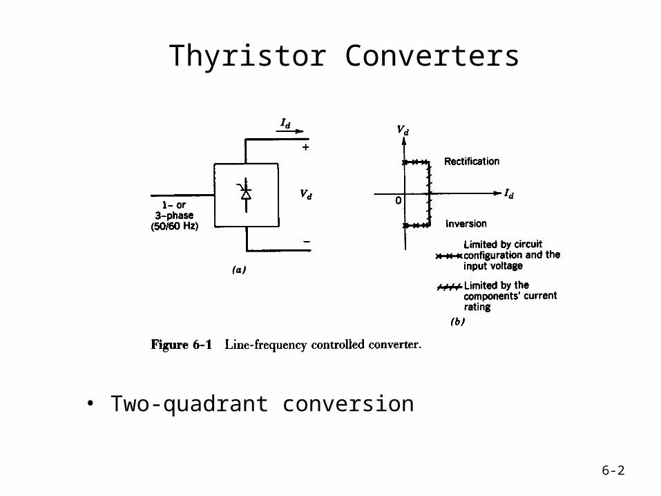
Thyristor Converters
• Two-quadrant conversion

6-3
Primitive circuits with thyristors

6-4
Thyristor Triggering
• ICs available

6-5
Full-Bridge Thyristor Converters
• Single-phase and three-phase

6-6
Single-Phase Thyristor Converters
• Two groups with two thyristor each

6-7
1-Phase Thyristor Converter Waveforms
• Assuming zero ac-side inductance

6-8
Average DC Output Voltage
• Assuming zero ac-side inductance

6-9
Input Line-Current Waveforms
• Harmonics, power and reactive power

6-10
1-Phase Thyristor Converter
• Finite ac-side inductance; constant dc output current

6-11
Thyristor Converter Waveforms
• Finite ac-side inductance

6-12
Thyristor Converter: Discontinuous Mode
• This mode can occur in a dc-drive at light loads

6-13
Thyristor Converter Waveforms
• PSpice-based simulation

6-14
Thyristor Converter Waveforms: Discontinuous Conduction Mode
• PSpice-based simulation

6-15
DC Voltage versus Load Current
• Various values of delay angle
6-16
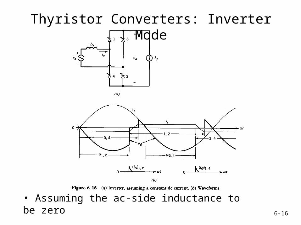
Thyristor Converters: Inverter Mode
• Assuming the ac-side inductance to be zero

6-17
Thyristor Converters: Inverter Mode
• Family of curves at various values of delay angle
6-18
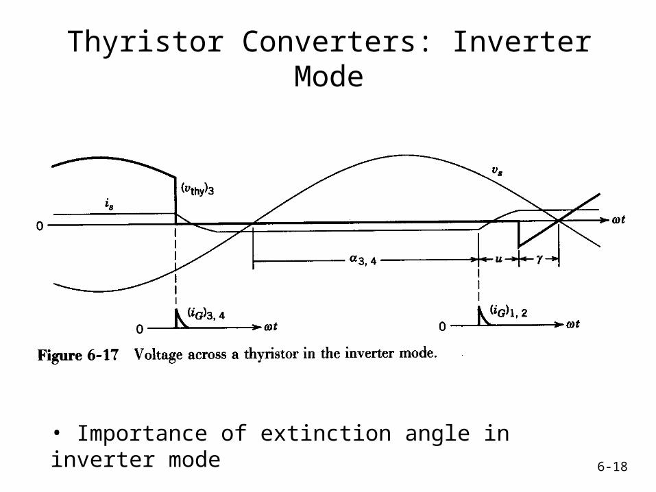
Thyristor Converters: Inverter Mode
• Importance of extinction angle in inverter mode

6-19
Thyristor Converters: Inverter Mode
• Waveforms at start-up
6-20
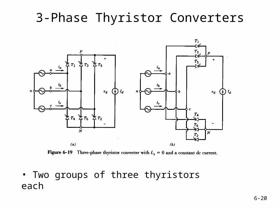
3-Phase Thyristor Converters
• Two groups of three thyristors each

6-21
3-Phase Thyristor Converter Waveforms
• Zero ac-side inductance; purely dc current

6-22
DC-side voltage waveforms assuming zero ac-side inductance
6-23
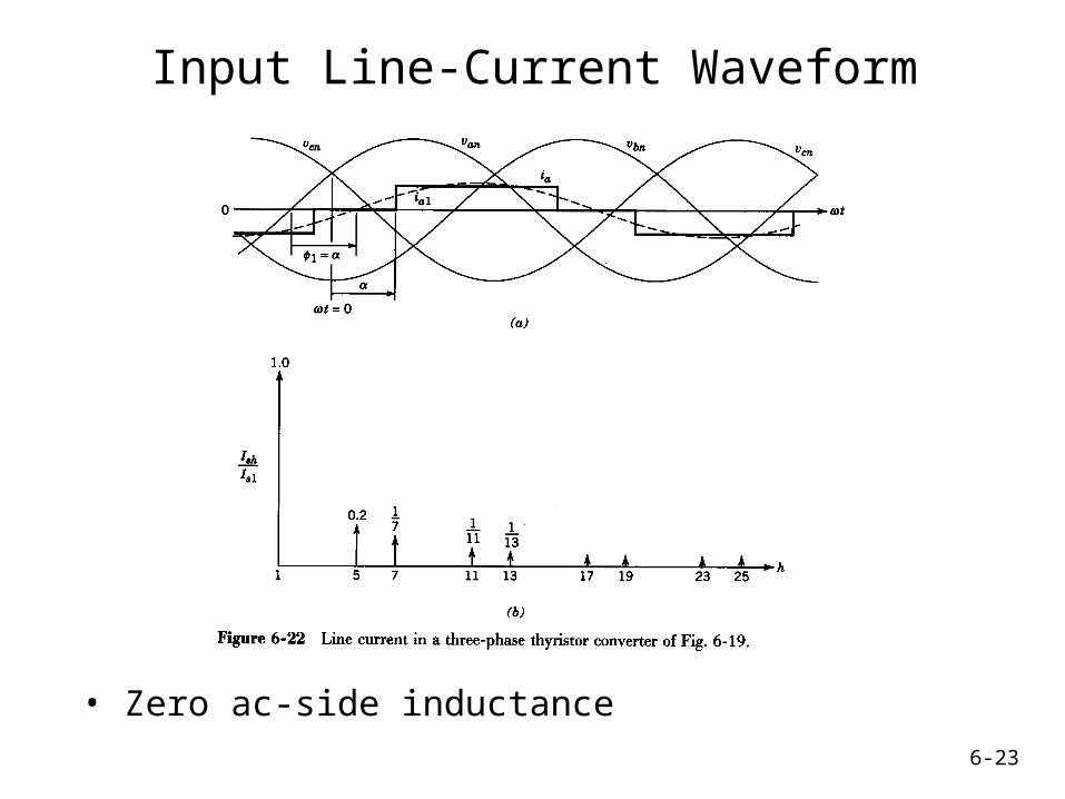
Input Line-Current Waveform
• Zero ac-side inductance

6-24
Input line-current waveforms assuming zero ac-side inductance

6-25
Three-Phase Thyristor Converter
• AC-side inductance is included
6-26
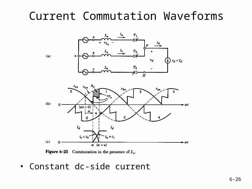
Current Commutation Waveforms
• Constant dc-side current

6-27
Input Line-Current Waveform
• Finite ac-side inductance
6-28
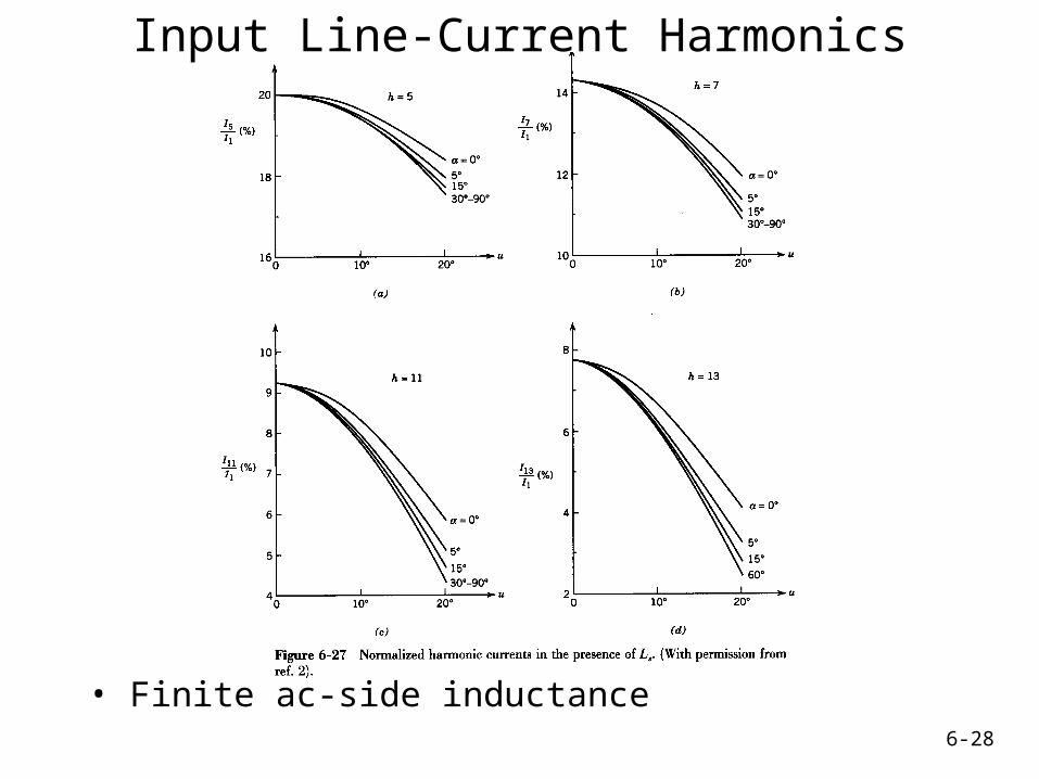
Input Line-Current Harmonics
• Finite ac-side inductance

6-29
Input Line-Current Harmonics
• Typical and idealized

6-30
Three-Phase Thyristor Converter
• Realistic load

6-31
Thyristor Converter Waveforms
• Realistic load; continuous-conduction mode

6-32
Thyristor Converter Waveforms
• Realistic load; discontinuous-conduction mode

6-33
Thyristor Inverter
• Constant dc current

6-34
Thyristor Inverter Waveforms
• Finite ac-side inductance

6-35
Thyristor Inverter
• Family of curves at various values of delay angle

6-36
Thyristor Inverter Operation
• Importance of extinction angle
6-37
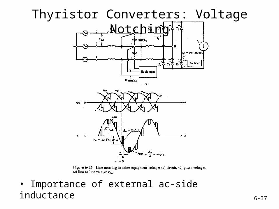
Thyristor Converters: Voltage Notching
• Importance of external ac-side inductance

6-38
Limits on Notching and Distortion
• Guidelines
6-39
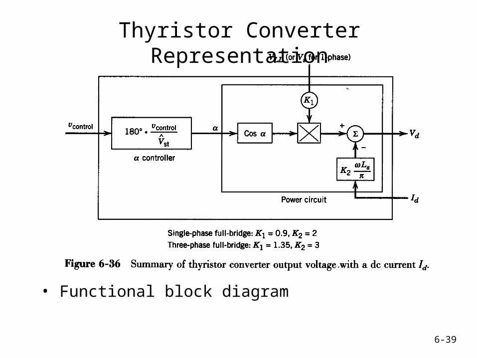
Thyristor Converter Representation
• Functional block diagram