Embed Size (px)
Citation preview
5V-Crimp
Table of Contents
Important InformationInstallation InformationTechnical InformationTrims and Flashings IllustrationRoofing Installation Details Fascia Cover (FC-5/FC-7/FC-9) Eave Drip (ED-1) Eave Flashing (EF-3) Preformed Valley (PV-1/PV-2) End Wall Flashing (EW-1) Side Wall Flashing (SW-1) Transition Flashing (TF-1) Gambrel Flashing (GF-1) Gable Rake (GR-2) Gable Rake (GR-4) High Side Eave (HS-2) Hip Cap (RC-2) Ridge Cap (RC-3) Ridge Cap (RC-8) Vented Ridge with Venturi Vent Vented Ridge with Miami Dade Profile Vent Pipe BootFastener GuideSealants and AccessoriesHelpful FormulasFlashing Angle Specifier Chart
2456
8910111213141516171819202122232425262728

5V-C
rim
p
Important Information
2
Finishes40-year warranted SemCoat Plus is a fluoroceram premium coating manufactured by BASF/Morton International Inc. It contains 70% Kynar 500 or Hylar 5000 PVDF resin over Galvalume ASTM-A792 structural steel grade 50.
35-year warranted SemCoat SP is a siliconized poly-ester premium coating applied to a galvanized steel substrate coated with zinc (G90). This finish consists of a primer coat top and bottom and the primary color applied to the top of the panel.
Panels are also available in 25-year warranted Acrylic coated Galvalume ASTM-A792 structural steel grade 50 and non-warranted hot dipped G-90 galvanized mill finish. Please note, acrylic coated Galvalume panels may not weather uniformly after installation. This is not a defect in the product or a cause for rejection. If non-uniform weathering is a concern, Southeastern Metals recommends selection of a color-coated panel.
ColorsFor panel color selection, please refer to the Southeastern Metals Metal Roofing Color Chart.
Job Estimating and TakeoffsSoutheastern Metals offers this valuable service at no charge. In order to complete estimation requests, it is absolutely necessary that Southeastern Metals be furnished with detailed, accurate information and drawings regarding the project prior to assistance.
Southeastern Metals can assist customers in deter-mining the amount and length of material required for the project, but it is the customer’s responsibil-ity to review and field verify the material required to complete the project. Southeastern Metals will not be held accountable for incorrect lengths and quantities. Prior to ordering and installing materials, all dimensions should be verified by field measurements.
Job Site Delivery AvailableThe job site delivery disclaimer must be completed to use this service.
Miami-Dade County and Local Code ComplianceSoutheastern Metals’ 26 Gauge 5V-Crimp products are Miami-Dade County approved and comply with the most recent testing requirements. Contact our techni-cal department for a copy of our current Miami-Dade County NOA compliance report if one is required for your purposes.
Building codes for metal roofing applications vary by county and project. For information regarding pertinent building code requirements and ordinances, contact your local building code organization.
Southeastern Metals acts only as the seller of roof-ing materials and has no control of the application of materials or the conditions under which they are applied. A registered engineer or architect of record for the project assumes the responsibility of detailing the applications.
WarrantiesAcrylic coated Galvalume panels are warranted not to perforate due to red rust for a period of 25 years provided the project installation meets the limitations detailed in Southeastern Metals’ warranty document. For full warranty coverage, panels must be installed more than one mile from an aggressive environment such as, but not limited to, salt water. Those projects within a 1/2 mile to one mile proximity of an aggres-sive environment are covered by a five-year warranty. Due to the characteristics of the coating, cosmetics cannot be controlled and are not covered by the warranty.
35-year SemCoat SP panels are warranted against paint peel, check, chip, or crack resulting from a manufacturer’s defect for a period of 35 years from the date of invoice provided the project installation meets the limitations detailed in Southeastern Metals’ SemCoat SP warranty document. For full warranty coverage, panels must be installed more than one mile from an aggressive environment such as, but not limited to, salt water. Those projects located within a 1/2 mile to one mile proximity of an aggressive environment are covered by ten year warranty. Excessive, non-uniform chalk and fade are covered for the first 10 years.
5V-Crimp
40-year SemCoat Plus panels are warranted against paint peel, check, chip, or crack resulting from a manufacturer’s defect for a period of 40 years from the date of invoice providing the project installation meets the limitations detailed in Southeastern Met-als’ SemCoat Plus warranty document.
Delivery, Handling and StorageProper care in storing and handling metal panels is essential in providing you with years of service. Panels should be installed immediately to prevent storage oxidation or paint peel. Any panels not im-mediately installed must be kept dry and stored in an indoor area. Extreme caution should be taken in order to prevent moisture penetration of the stack(s) by rain, snowfall or condensation. Condensation is moisture that accumulates naturally from the change in temperature of the material nested in a stack where adequate ventilation has been restrict-ed.
Store the panels off the ground, on wooden blocks with one end slightly elevated. Cut banding to allow the stack to expand and allow a small amount of ventilation. Cover the stack with loose canvas tarp or waterproof paper. Covering should be placed over the stack but never tightly secured to the ground to allow air flow. Do not cover metal with plastic as this can create condensation.
Safety PrecautionsIt is the responsibility of the buyer to ensure the safe installation of these product systems. Metal panels have sharp edges, therefore protective clothing and gloves should be utilized. To prevent eye injury, safety glasses must be worn when drilling or cutting steel panels. Steel panels can become slippery when wet. Use extreme care when walking on any roofing panel. Proper underlayment is necessary to prevent fall-through. Plywood is recommended on all non-structural panel applications. Do not work on steel panels when wet or when weather conditions are not suitable for safe installation.
Southeastern Metals recommends all installers comply with the Florida Fall Protection Act, all OSHA (Occupational Safety & Health Administration) requirements (#3146, dated 1995), and any other applicable safety rules or laws.
CancellationsSoutheastern Metals will honor cancellation prior to manufacturing. Any order which has already been manufactured is the property of the purchaser.
ClaimsAll claims of shortage, damage, etc. must be made within 48 hours of the date of receipt. Claims must be accompanied by a copy of the bill of lading verified by the shipper which must indicate shortages or damages as received. Southeastern Metals can not honor short-age or damage claims on freight carriers unless the carrier’s paperwork is duly noted.
DisclaimerThe information contained in this product manual is subject to change without notice. Southeastern Metals reserves the right to discontinue or modify products and installation methods at any time without notice and incurring no obligation. Contact Southeastern Metals to obtain the latest information.
5V-Crimp metal roofing panels are prone to oil canning, a wavy distortion in the flat or nearly flat area of the panel. Oil canning will not be considered a reason for rejection or claim.
Throughout this product manual each panel series is specified per Southeastern Metals recommended use and application of these products. The use of these products should not vary from these recommendations or should not be applied using another manufacturer’s specifications or guidelines. If you have any questions about any of the products and their appropriate appli-cations, please call Southeastern Metals.
NOTICE: The application details are for illustration purposes only. These details may not be suitable for all building designs or conditions. Projects should be engineered to confirm to building codes, regulations, and industry practices which are applicable. Consult Southeastern Metals for any additional information not outlined in this manual.
3

5V-C
rim
p
PanelThere are three critical measurements involving roof panels: the length required at the eave, the peak end and the amount of panel lap (if required). In each case a certain measurement is required. Check each measurement to ensure panel placement gives you the distance required at the eave, peak and endlap condition (if required). In most cases any variance can be taken out at the eave and peak.
AccessoriesThis publication details the standard line of trims and accessories for 5V-Crimp roofing applications. Additional trims, including custom accessories, are available upon request.
SubstrateIn residential applications, Southeastern Metals’ recommends the use of minimum 15/32 plywood or 7/16 OSB decking. In addition, we specify a 30# felt be installed in accordance with local building code requirements to control condensation. NOTE: Southeastern Metals does not recommend the use of square headed cap nails. If tin tabs are used to secure the 30# felt to the decking material, Southeastern Metals’ recommends a separation sheet of 15# felt or rosin paper be used over the 30# felt, applied in the same direction as the panels. If the building param-eters differ from those stated in the manufacturer’s recommended fastening schedule, specific fastening calculators must be computed by the engineer of record.
Metal Re-Roofing Over ShinglesSoutheastern Metals’ metal roofing panels may be installed over existing asphalt shingles, provided the roof decking integrity has been confirmed to be free of any moisture decay that would prevent un-level-ness or fastener pull out capacity. NOTE: Ordinances regarding roofing applications over existing shingles vary by county and state. Check your local building code organization for more information.
The panels may be applied directly over one layer of existing shingles, provided a separation sheet is installed on top to the shingles. We require a minimum 30# felt installed in the same direction as the panels.
Metal roofing can also be separated from the moisture barrier by optional 1” x 3” battens as furring, spaced a maximum of 16” on center and fastened according to our recommended application details. CAUTION: Direct contact between pressure treated lumber and metal roofing must be avoided to prevent corrosion.
Metal Roofing Fire Resistance RatingsSoutheastern Metals’ metal roofing panels have been ana-lyzed for fire resistance ratings according to test criteria set forth by Underwriters Laboratories “Standard Fire Tests of Building Construction and Materials” (ANSI/UL 263), and ASTM E119 and NFPA 251.
The fire resistance rating is for the total assembly and not just the external metal roofing panels. In general, the test criteria is to evaluate the assemblies ability to continue to support the imposed loads and to resist the passage of flame, high temperature, or hot gasses which will ignite combustible sub-assembly, framing, or decking materials from an exterior source. For detail information on specific assembly ratings see the UL Fire Resistance Directory.
Attaining a class “A” or “B” fire rating requires the installation of one of the following - a minimum ¼” thick Georgia Pacific “Dens Deck”; a minimum 4mm thick Partek Insulation’s, Inc. “Roctex”; a minimum 52 ½# Elks “Versa Shield”; a minimum 5/8” water resistant type X gypsum sheeting with treated core and facer; or any other product with a current product approval - over the combustible deck prior to installing the metal roofing panels.
Trimming and Cutting Steel PanelsWhether cutting with the profile (length-wise) or across the panel (width wise), it is best to use an electric nibbler, shears or hand tin-snips. It is very important to cut panels one at a time with the finish side of the panel facing down on wood blocks. Care should be taken to ensure that the hot metal particles and filings from cutting and securing the panel do not become embedded in the panel.
CAUTION: Filings from screw and panel cuttings must be cleaned off the panel after screws have been applied through the panel to avoid rust marks or “bleeding” on the panels. Failure to comply with the above procedures relieves Southeastern Metals, and its parent company, Gibraltar Industries, of responsibility for any resulting damage to, or deterioration of the finish and voids any paint or finish warranty.
Installation Information
4
5V-Crimp
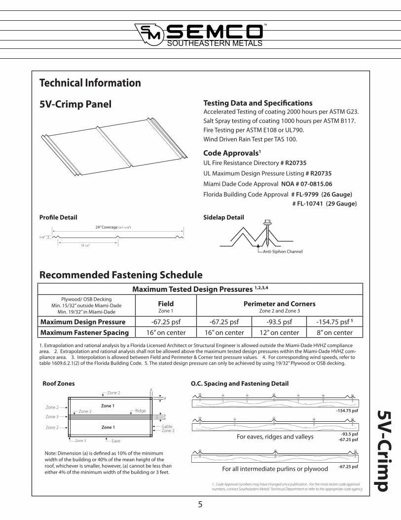
Technical Information
Accelerated Testing of coating 2000 hours per ASTM G23. Salt Spray testing of coating 1000 hours per ASTM B117. Fire Testing per ASTM E108 or UL790. Wind Driven Rain Test per TAS 100.
Testing Data and Specifications
UL Fire Resistance Directory # R20735
UL Maximum Design Pressure Listing # R20735
Miami Dade Code Approval NOA # 07-0815.06
Florida Building Code Approval # FL-9799 (26 Gauge) # FL-10741 (29 Gauge)
Code Approvals1
5V-Crimp Panel
1. Extrapolation and rational analysis by a Florida Licensed Architect or Structural Engineer is allowed outside the Miami-Dade HVHZ compliance area. 2. Extrapolation and rational analysis shall not be allowed above the maximum tested design pressures within the Miami-Dade HVHZ com-pliance area. 3. Interpolation is allowed between Field and Perimeter & Corner test pressure values. 4. For corresponding wind speeds, refer to table 1609.6.2.1(2) of the Florida Building Code. 5. The stated design pressure can only be achieved by using 19/32” Plywood or OSB decking.
Recommended Fastening Schedule
Note: Dimension (a) is defined as 10% of the minimum width of the building or 40% of the mean height of the roof, whichever is smaller, however, (a) cannot be less than either 4% of the minimum width of the building or 3 feet.
Sidelap Detail
For eaves, ridges and valleys
-67.25 psfFor all intermediate purlins or plywood
-154.75 psf
-93.5 psf-67.25 psf
O.C. Spacing and Fastening Detail
Anti-Siphon Channel
24” Coverage (+/- 1/16”)
11 1/2”
7/16”
5
Profile Detail
Roof Zones
Maximum Tested Design Pressures 1,2,3,4
Plywood/ OSB DeckingMin. 15/32” outside Miami-Dade
Min. 19/32” in Miami-DadeFieldZone 1
Perimeter and CornersZone 2 and Zone 3
Maximum Design Pressure -67.25 psf -67.25 psf -93.5 psf -154.75 psf 5
Maximum Fastener Spacing 16” on center 16” on center 12” on center 8” on center
Zone 1
Zone 2
aa
a
aZone 2
Eave
Zone 3
Zone 2
Zone 2Zone 2
Gable
Ridge
Zone 3
Zone 1
1. Code Approval numbers may have changed since publication. For the most recent code approval numbers, contact Southeastern Metals’ Techincal Department or refer to the appropriate code agency.
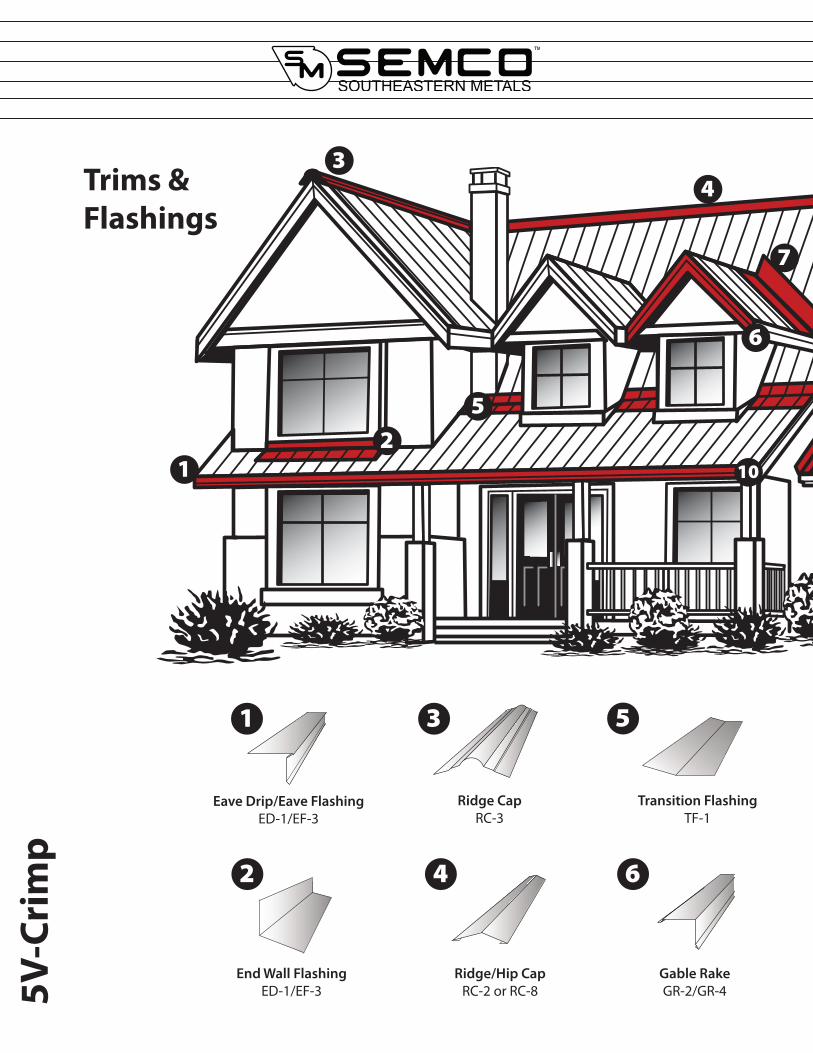
Trims & Flashings
5V-C
rim
p
7
6
5
4
21
Ridge CapRC-3
Transition FlashingTF-1
Ridge/Hip CapRC-2 or RC-8
Eave Drip/Eave FlashingED-1/EF-3
End Wall FlashingED-1/EF-3
Gable RakeGR-2/GR-4
3
5
62 4
31
10
11
8
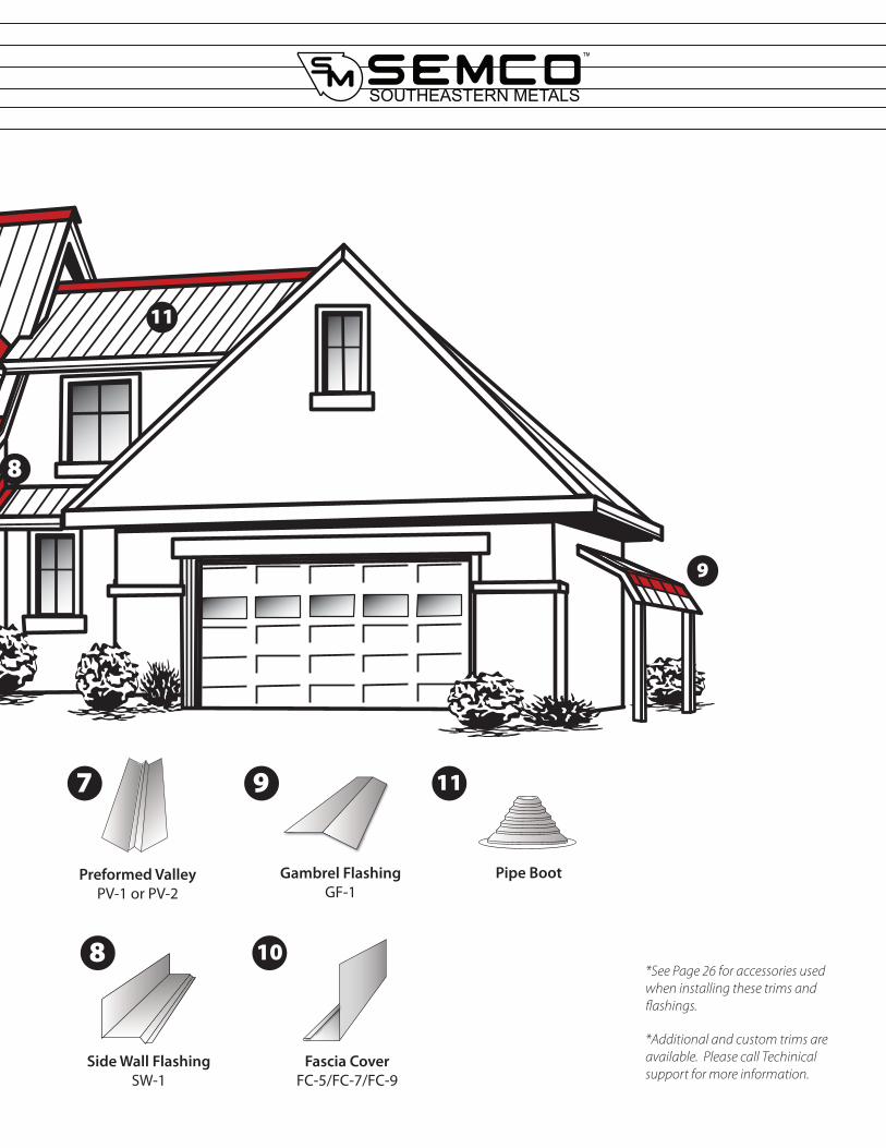
Gambrel FlashingGF-1
Preformed ValleyPV-1 or PV-2
Side Wall FlashingSW-1
Fascia CoverFC-5/FC-7/FC-9
Pipe Boot
*Additional and custom trims are available. Please call Techinical support for more information.
*See Page 26 for accessories used when installing these trims and flashings.
11
8 10
97
9

5V-C
rim
p
Fascia Cover FC-5/FC-7/FC-9 (10’ Lengths)
Component Details
8
Item Fascia Size “A”FC-5 2” x 6” 5”
FC-7 2” x 8” 7”
FC-9 2” x 10” 9”
Open Hem
1/2”
“A”
2 1/2”
FC-5FC-7FC-9
1 1/2”
1/2”
1/2”
1/2”
Cleat CL-4
Eave Drip or Eave Flashing
FC-5/FC-7/FC-9
CL-4
Decking
Fastenerby others
Fastenerby others
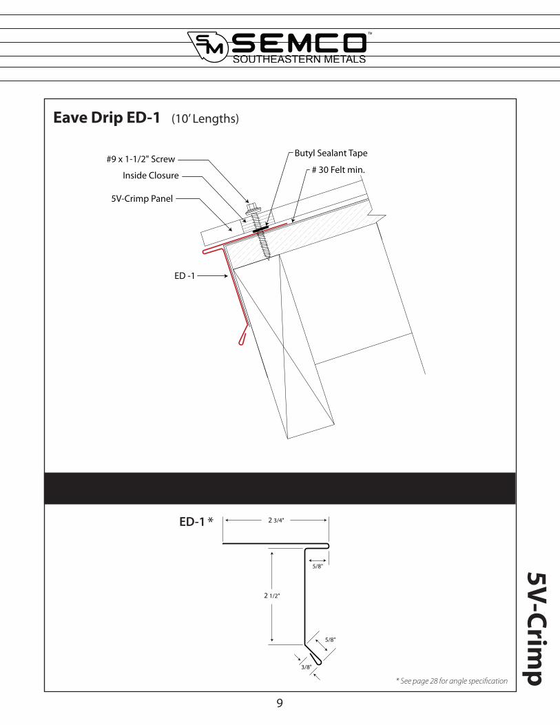
Eave Drip ED-1 (10’ Lengths)
ED -1
#9 x 1-1/2" Screw# 30 Felt min.
5V-Crimp Panel
Butyl Sealant Tape
Inside Closure
Component Details
2 3/4"
5/8"
2 1/2"
5/8"
3/8"
ED-1
9
5V-Crimp
* See page 28 for angle specification
*
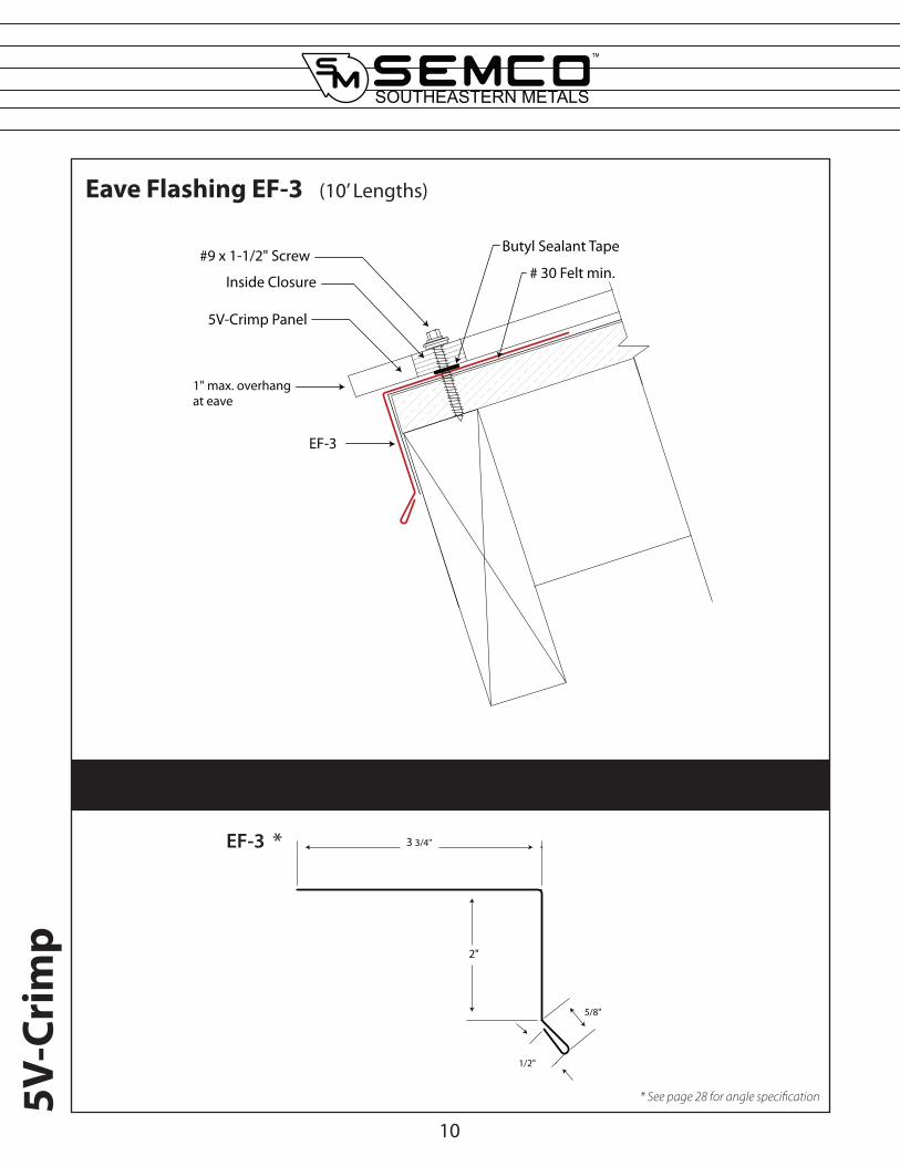
Eave Flashing EF-3 (10’ Lengths)
EF-3
1" max. overhang at eave
#9 x 1-1/2" Screw# 30 Felt min.
5V-Crimp Panel
Butyl Sealant Tape
Inside Closure
Component Details
3 3/4"
5/8"
1/2"
2"
EF-3
10
5V-C
rim
p
* See page 28 for angle specification
*

Preformed Valley PV-1/PV-2 (10’ Lengths)
Component Details
PV -1/PV -2
6"min.
# 30 Felt min.
Decking
#9 x 1-1/2" Screw5V-Crimp Panel
Butyl Sealant
Inside ClosureInside Closure
12 3/4"
1"
60°
80°
100°
80°
60°
1"
12 1/4"
100°
1/2"
PV-1 - Unhemmed PV-2 - Hemmed
11
5V-Crimp
* See page 28 for angle specification
* *
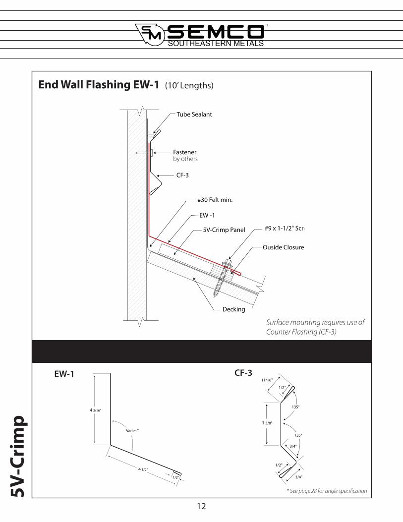
End Wall Flashing EW-1 (10’ Lengths)
Component Details
EW -1
Ouside Closure
#9 x 1-1/2" Screw
#30 Felt min.
Decking
5V-Crimp Panel
CF-3
Fastenerby others
Tube Sealant
Varies
4 3/16"
1/2"
4 1/2"
EW-1
12
5V-C
rim
p
Surface mounting requires use of Counter Flashing (CF-3)
CF-31/2"
11/16"
1 3/8"
3/4"
3/4"
1/2"
135°
135°
* See page 28 for angle specification
*
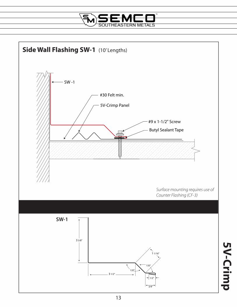
Side Wall Flashing SW-1 (10’ Lengths)
Component Details
SW -1
5V-Crimp Panel
#30 Felt min.
#9 x 1-1/2" Screw
Butyl Sealant Tape
3 3/8"
3 1/2"
1 1/16"
3/4"
1/2"
135°
135°
SW-1
13
5V-Crimp
Surface mounting requires use of Counter Flashing (CF-3)
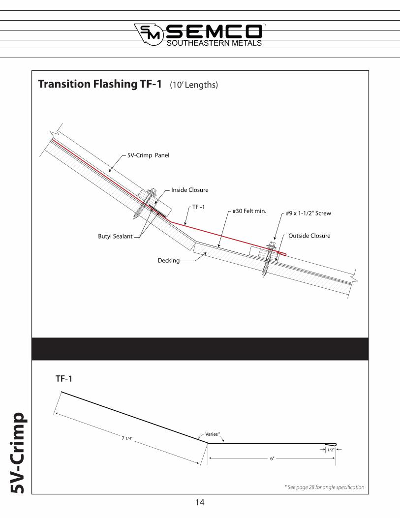
Transition Flashing TF-1 (10’ Lengths)
Component Details
TF -1
5V-Crimp Panel
Outside Closure
Inside Closure
Decking
#9 x 1-1/2" Screw#30 Felt min.
Butyl Sealant
7 1/4"
1/2"
6"
Varies
TF-1
14
5V-C
rim
p
* See page 28 for angle specification
*

Gambrel Flashing GF-1 (10’ Lengths)
Component Details
GF -1
5V-Crimp Panel
Outside Closure
Inside Closure
#9 x 1-1/2" Screw
#30 Felt min.
Decking
5V-Crimp Panel
Butyl Sealant
Varies
7 1/4"
6"
1/2"
GF-1
15
5V-Crimp
* See page 28 for angle specification
*
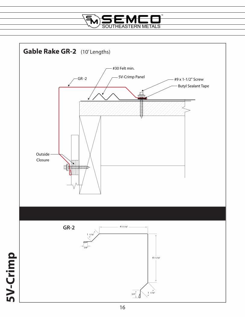
Gable Rake GR-2 (10’ Lengths)
Component Details
GR -2
#30 Felt min.
Butyl Sealant Tape
5V-Crimp Panel
Outside Closure
#9 x 1-1/2" Screw
3/4"
3/8"
1 1/16"
4 11/16"
4 11/16"
1 1/16"
GR-2
16
5V-C
rim
p
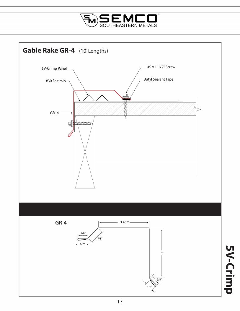
Gable Rake GR-4 (10’ Lengths)
Component Details
GR -4
#9 x 1-1/2" Screw
#30 Felt min.
5V-Crimp Panel
Butyl Sealant Tape
1/2"
5/8"
7/8"
3 1/16"
3"
5/8"
1/2"
GR-4
17
5V-Crimp

High Side Eave HS-2 (10’ Lengths)
Component Details
18
HS -2
#9 x 1-1/2" Screw
# 30 Felt min.
Decking
5V-Crimp Panel
Outside Closure
3/8"
3 7/8"
5/8"
1/2"
3 7/8"
HS-2
5V-C
rim
p
* See page 28 for angle specification
*

Hip Cap RC-2 (10’ Lengths)
Component Details
19
1/2"
7/8"
4 1/8"
1 3/8"
136°
135°
RC-2
RC -2
Max.1 1/2"
Universal Closure
#30 Felt min.
#9 x 2-1/2" Screw
5V-Crimp Panel
DeckingButyl Sealant
5V-Crimp
RC -2
Max.1 1/2"
#30 Felt min.
6" Seal Tape
#9 x 2-1/2" Screw
5V-Crimp Panel
Decking
Option 2
Option 1
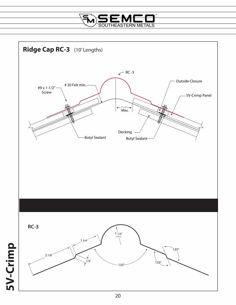
Ridge Cap RC-3 (10’ Lengths)
Component Details
1 1/2"
Max.
#9 x 1-1/2" Screw
Outside Closure
5V-Crimp Panel
# 30 Felt min.
Decking
RC -3
Butyl SealantButyl Sealant
1 1/4" radius
135°135°
135°
1 3/4"
1/4"
2 7/8"
RC-3
20
5V-C
rim
p
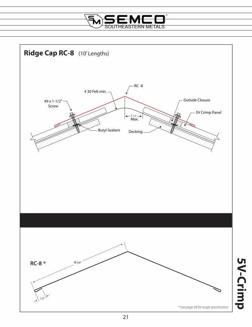
Ridge Cap RC-8 (10’ Lengths)
Component Details
1 1/2"
Max.
RC -8
#9 x 1-1/2" Screw
Outside Closure
5V Crimp Panel
# 30 Felt min.
DeckingButyl Sealant
1/2"
6 3/8"RC-8
21
5V-Crimp
* See page 28 for angle specification
*
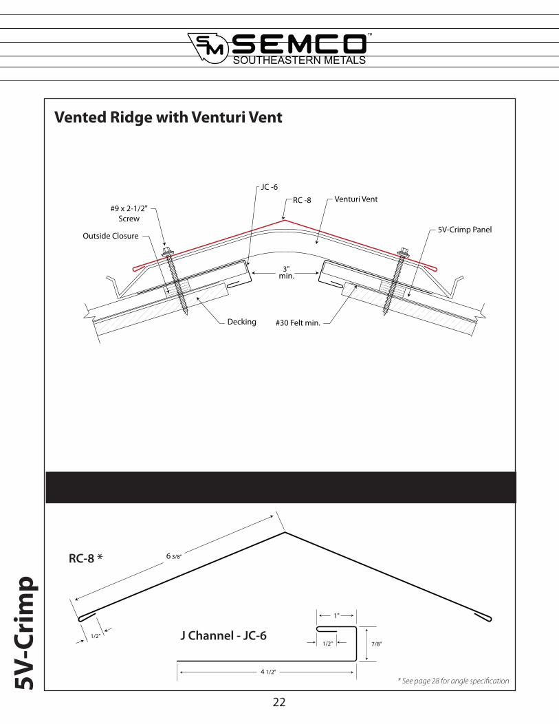
Vented Ridge with Venturi Vent
Component Details
Venturi Vent#9 x 2-1/2"
Screw
RC -8
Decking
Outside Closure
3"min.
#30 Felt min.
JC -6
5V-Crimp Panel
1/2"
6 3/8"RC-8
4 1/2"
7/8"
1"
1/2"J Channel - JC-6
22
5V-C
rim
p
* See page 28 for angle specification
*
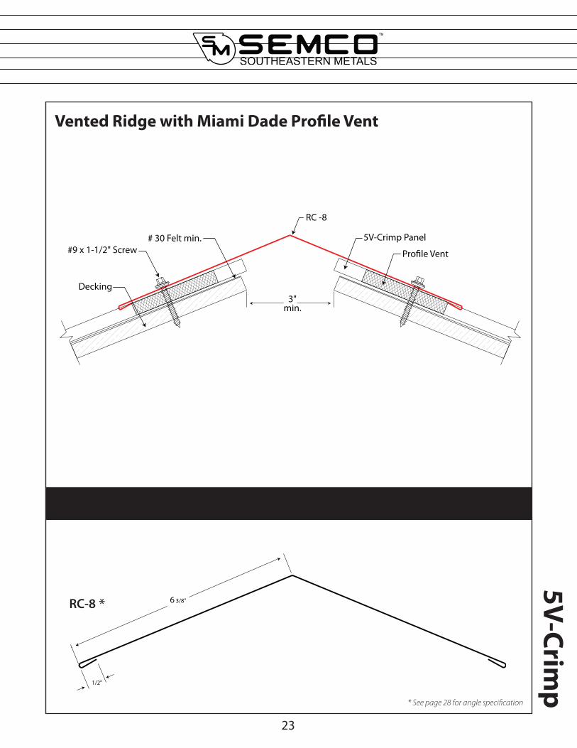
Vented Ridge with Miami Dade Profile Vent
Component Details
RC-8
23
1/2"
6 3/8"
3"min.
RC -8
#9 x 1-1/2" Screw Pro�le Vent
5V-Crimp Panel# 30 Felt min.
Decking
5V-Crimp
* See page 28 for angle specification
*
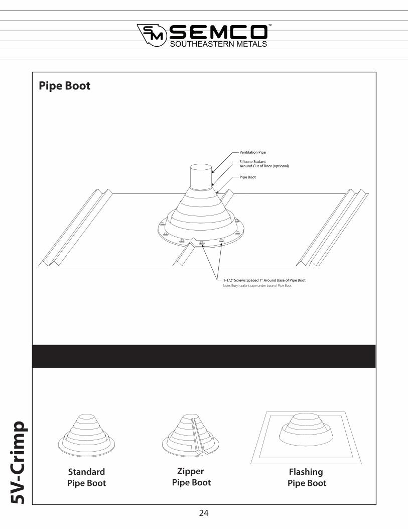
Pipe Boot
Component Details
1-1/2" Screws Spaced 1" Around Base of Pipe BootNote: Butyl sealant tape under base of Pipe Boot
Pipe Boot
Silicone SealantAround Cut of Boot (optional)
Ventilation Pipe
24
5V-C
rim
p
Standard Pipe Boot
Zipper Pipe Boot
Flashing Pipe Boot
25
5V-Crimp
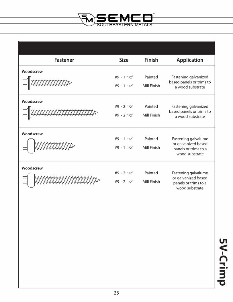
Fastener Guide
Fastener Size Finish Application
#9 - 1 1/2” Painted Fastening galvanized based panels or trims to
a wood substrate#9 - 1 1/2” Mill Finish
Woodscrew
Woodscrew
Fastening galvalume or galvanized based panels or trims to a
wood substrate
Woodscrew
Woodscrew
#9 - 2 1/2” Painted
#9 - 2 1/2” Mill Finish
Fastening galvanized based panels or trims to
a wood substrate
#9 - 1 1/2” Painted
#9 - 1 1/2” Mill Finish
#9 - 2 1/2” Painted
#9 - 2 1/2” Mill Finish
Fastening galvalume or galvanized based panels or trims to a
wood substrate

26
5V-C
rim
p
Inside Closure Strip
Outside Closure Strip
UniversalClosure Strip
Sealants and Accessories
Touch Up PaintVenturi Vent Profile Vent
PAINT
Hip Sealant Tape Butyl Sealant Tape Tube Sealant
5V-Crimp
27
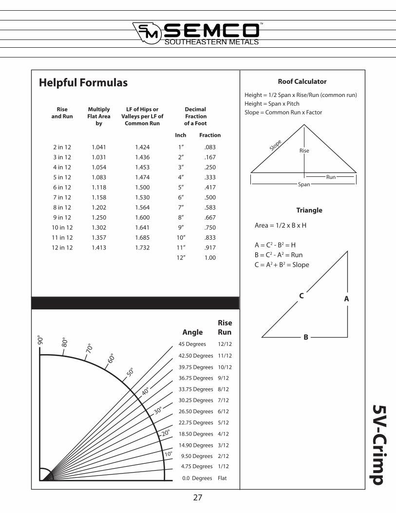
Helpful Formulas
Roof Slope Conversion Table with Roof Pitch Multiplier
Rise and Run
Multiply Flat Area
by
LF of Hips or Valleys per LF of
Common Run
Decimal Fraction of a Foot
Inch Fraction
2 in 12 1.041 1.424 1” .083
3 in 12 1.031 1.436 2” .167
4 in 12 1.054 1.453 3” .250
5 in 12 1.083 1.474 4” .333
6 in 12 1.118 1.500 5” .417
7 in 12 1.158 1.530 6” .500
8 in 12 1.202 1.564 7” .583
9 in 12 1.250 1.600 8” .667
10 in 12 1.302 1.641 9” .750
11 in 12 1.357 1.685 10” .833
12 in 12 1.413 1.732 11” .917
12” 1.00
Triangle
Area = 1/2 x B x H
A = C2 - B2 = HB = C2 - A2 = RunC = A2 + B2 = Slope
C A
B
Roof Calculator
Height = 1/2 Span x Rise/Run (common run)Height = Span x PitchSlope = Common Run x Factor
RiseSlope
SpanRun
90°
80°
70°
60°
50°
40°
30°
20°
10°
45 Degrees
42.50 Degrees
39.75 Degrees
36.75 Degrees
33.75 Degrees
30.25 Degrees
26.50 Degrees
22.75 Degrees
18.50 Degrees
14.90 Degrees
9.50 Degrees
4.75 Degrees
0.0 Degrees
12/12
11/12
10/12
9/12
8/12
7/12
6/12
5/12
4/12
3/12
2/12
1/12
Flat
AngleRiseRun
28
5V-C
rim
p
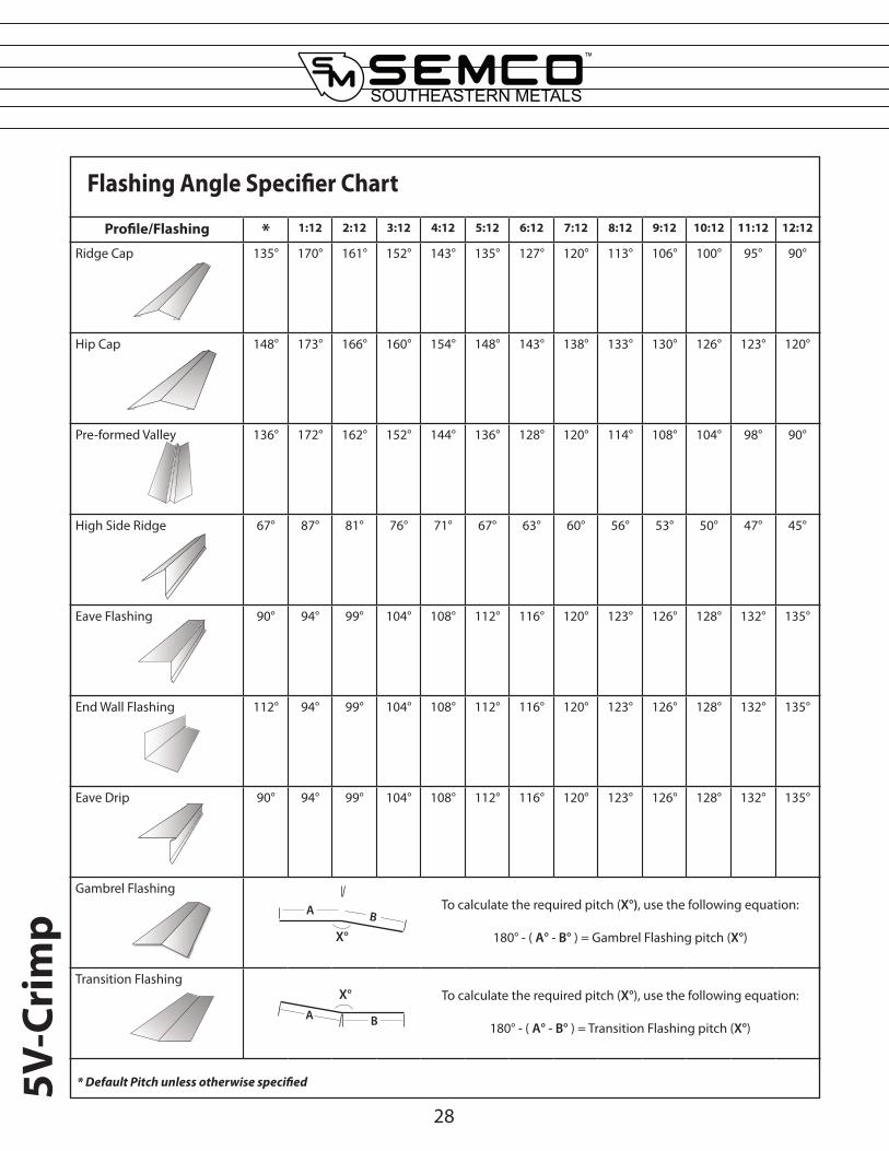
Profile/Flashing * 1:12 2:12 3:12 4:12 5:12 6:12 7:12 8:12 9:12 10:12 11:12 12:12
Ridge Cap 135° 170° 161° 152° 143° 135° 127° 120° 113° 106° 100° 95° 90°
Hip Cap 148° 173° 166° 160° 154° 148° 143° 138° 133° 130° 126° 123° 120°
Pre-formed Valley 136° 172° 162° 152° 144° 136° 128° 120° 114° 108° 104° 98° 90°
High Side Ridge 67° 87° 81° 76° 71° 67° 63° 60° 56° 53° 50° 47° 45°
Eave Flashing 90° 94° 99° 104° 108° 112° 116° 120° 123° 126° 128° 132° 135°
End Wall Flashing 112° 94° 99° 104° 108° 112° 116° 120° 123° 126° 128° 132° 135°
Eave Drip 90° 94° 99° 104° 108° 112° 116° 120° 123° 126° 128° 132° 135°
Gambrel FlashingTo calculate the required pitch (X°), use the following equation:
180° - ( A° - B° ) = Gambrel Flashing pitch (X°)
Transition FlashingTo calculate the required pitch (X°), use the following equation:
180° - ( A° - B° ) = Transition Flashing pitch (X°)A B
X°
A B
X°
Flashing Angle Specifier Chart
* Default Pitch unless otherwise specified