Embed Size (px)
Citation preview

5TROTK�.KRV
5TROTK�.KRV
/TZXUJ[IZOUT
)XKGZOTM�G�6KTM[OT
3UJKROTM
6GOTZOTM
3KT[Y
-RUYYGX_
/TJK^
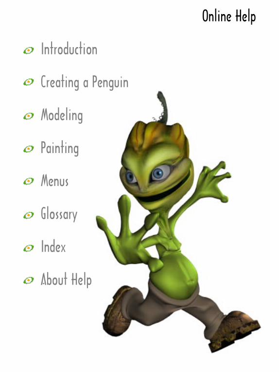
'HU[Z�.KRV

/TZXUJ[IZOUTNendo is an integrated Modeling and Painting tool for creating 3D objects. There are two modes in Nendo, Model and Paint.
3UJKRIn Model, you create and modify objects. You can start with one of the primitives supplied with Nendo or import objects in a variety of file formats. Once you’ve loaded an object, you manipulate points, edges, or faces to add detail where you need it. As you model, you can change how the object is displayed, for example, choosing be-tween shaded and wireframe mode. Plus, you can view your object from any angle by rotating the camera.
6GOTZAfter you create an object, simply click on the Paint button and you are ready to paint directly onto the surface of your object in 3D. Once in Paint, a toolbox containing a wide variety of configurable, easy-to-use brushes and tools appears. You use these tools to color and paint your objects. You can paint on the object with imported im-ages or colors created in the Color Mixer. As in Model, you can ro-tate the camera to view your object from any angle.

)XKGZOTM�G�6KTM[OTThis tutorial shows you how to model and paint a character. It also introduces you to many of Nendo’s Model commands and Paint tools while explaining the buttons, menus, and toolbars.
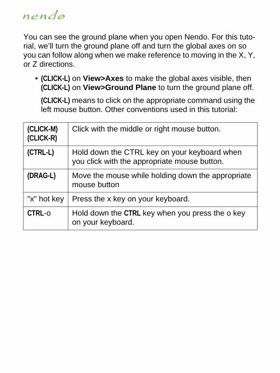
You can see the ground plane when you open Nendo. For this tuto-rial, we’ll turn the ground plane off and turn the global axes on so you can follow along when we make reference to moving in the X, Y, or Z directions.
• (CLICK-L) on View>Axes to make the global axes visible, then (CLICK-L) on View>Ground Plane to turn the ground plane off.
(CLICK-L) means to click on the appropriate command using the left mouse button. Other conventions used in this tutorial:
(CLICK-M)(CLICK-R)
Click with the middle or right mouse button.
(CTRL-L) Hold down the CTRL key on your keyboard when you click with the appropriate mouse button.
(DRAG-L) Move the mouse while holding down the appropriate mouse button
"x" hot key Press the x key on your keyboard.
CTRL-o Hold down the CTRL key when you press the o key on your keyboard.

■ To create a penguin:
1. Create a cube.
(CLICK-L) on File>Add>Cube.
NOTE...
You can also create a cube if you (CLICK-R) in the Model window and then (CLICK-L) on Cube in the list that appears.
2. (CLICK-L) on the Faces button, shown below.
The buttons let you pick what kind of element you want to work with. The buttons are, from left to right, as follows:
Free Lets you select any element type. Once you have begun a collection of one type of element, you can collect only that element type.
Vertices Lets you select vertices.
Edges Lets you select edges.
Faces Lets you select faces.
Objects Lets you select one or more objects.
Faces button

As you pass the mouse cursor over any of the buttons, the Sta-tus Bar at the bottom of the Nendo window shows the selected element type. This is true for all of the screen elements, com-mands, and tools in Nendo.
3. Select the cube’s top and bottom faces.
To select the top face:
• Highlight the face (it turns green) and then click on it (the face turns yellow).
• When you move the mouse away from the face, the face turns red. It is still selected, but it is no longer highlighted.
In order to select the bottom face, you have to move the cam-era. The camera is what you use to look at the window. To move the camera:
• (CLICK-M) (or use (CTRL-R) if you have a two-button mouse) on the window to start the camera
• After you start the camera, moving the mouse moves the camera.
• If you need to zoom the camera in or out, (CLICK-R) and drag or (DRAG-M).
• To spin the camera around an object, (DRAG-M) or (CLICK-R) and drag the mouse left or right after starting the camera, then release the mouse button while still moving the mouse.
• When you can see the bottom face, (CLICK-L) in the window to stop the camera. Then, select the bottom face.

4. After you’ve selected both faces, (CLICK-R) in the Model window to bring up the Faces Operations menu.
The Faces Operations menu lists all of the operations that can be performed on faces. Whenever an element is highlighted in the Model window, you can (CLICK-R) in the Model window, to see the Operations menu for that element type.

5. (CLICK-L) on Extrude>Normal.
Extrude the faces until you have three cubes stacked on top of each other. In order to see the cube with the new extrusions, you may need to move the camera back a bit.
6. Deselect the faces using the one of the following:
• Press the space bar to deselect any elements
• (CLICK-L) on Select>Clear Selection
• (CLICK-L) on each of the faces that you have selected
• (CLICK-L) on one of the buttons
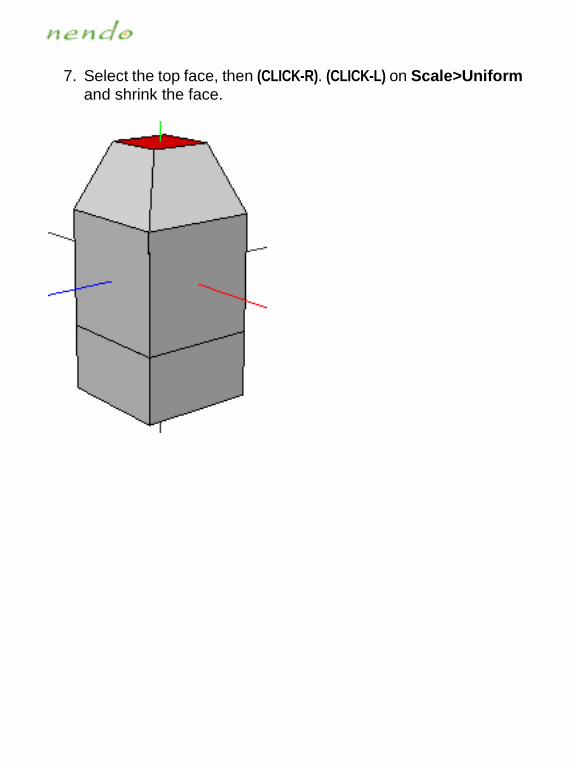
7. Select the top face, then (CLICK-R). (CLICK-L) on Scale>Uniform and shrink the face.
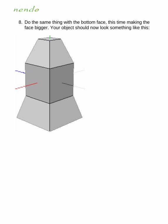
8. Do the same thing with the bottom face, this time making the face bigger. Your object should now look something like this:

9. With the bottom face still selected, (CLICK-L) on Extrude>Normal and pull the face down.

10. Use Scale>Uniform to shrink the bottom face.
11. (CLICK-L) on the Edges button and select the horizontal edges that form the bottom of the original cube.

12. (CLICK-R) in the Model window to bring up the Edges Opera-tions menu, then (CLICK-L) on Scale>Uniform. Scale the edges out until your model is pear shaped.
13. With the Edges button still selected, select all of the horizontal edges on your character, then (CLICK-L) on Connect.

14. Select all of the new vertical edges on your character (shown below). Then, (CLICK-L) on Select>Select Adjacent>Vertices to select all of the vertices adjacent to these edges.
NOTE...
You can also use the "v" hot key to select the vertices of the currently selected elements.
15. In the Vertices Operations menu, (CLICK-L) on Scale>X and pull those sides out slightly.
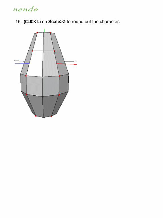
16. (CLICK-L) on Scale>Z to round out the character.
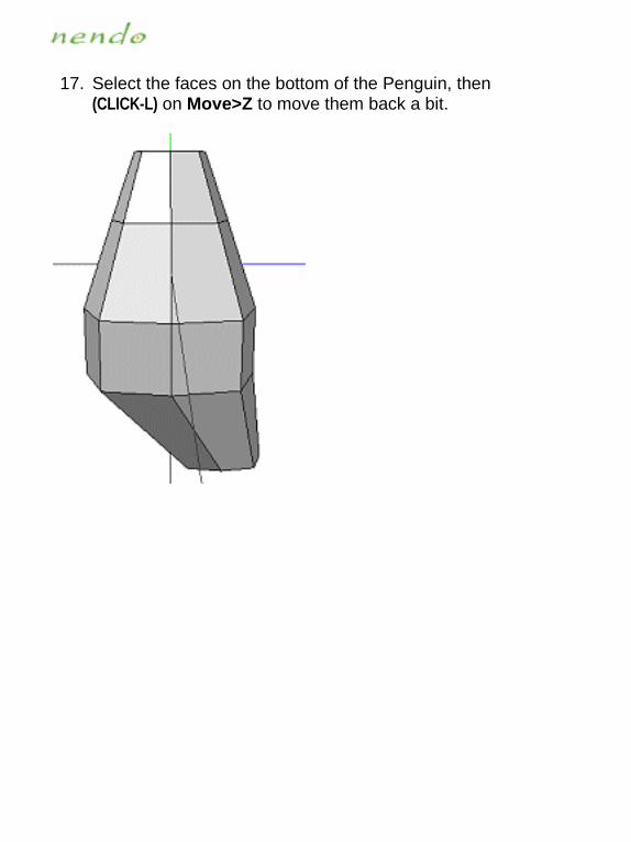
17. Select the faces on the bottom of the Penguin, then (CLICK-L) on Move>Z to move them back a bit.
([ORJOTM�ZNK�6KTM[OT«Y�=OTMY18. Press the "x" hot key to align the camera with the X axis.
NOTE...
You can use the SHIFT key with the "x", "y", or "z" hot key to align the camera with the -X, -Y, or -Z axes.
19. Press the space bar hot key to deselect the faces on the bottom of the penguin.
20. Next select the face shown below and the corresponding face on the other side of the penguin. These will become the pen-guin’s wings.
21. Once the faces are selected, press the "z" hot key to align the camera with the Z axis.
Select this face

22. In the Faces Operations menu, (CLICK-L) on Extrude>Normal and pull the wings out from the body.
23. With the faces still selected, (CLICK-L) on Move>Y in the Faces Operations menu to move the wings down.
24. Press the "v" hot key to select the vertices of the selected faces, then (CLICK-L) on Scale>Uniform to bring the wings towards the body as you scale the vertices around the midpoint of the collection.
25. Select the bottom edges of the wings and (CLICK-L) on Scale>Uniform to taper the wings.
26. (CLICK-L) on Extrude>Normal and pull the edges down.

27. (CLICK-L) on Move>Z to move the edges of the wing back.

)XKGZOTM�ZNK�:GOR28. Press the "z" hot key to aim the camera at the penguin’s back.
29. Select the two edges shown below to start the tail.

30. (CLICK-L) on Extrude>Normal and pull the edges out.
31. With the edges still selected, (CLICK-L) on Extrude>Normal and pull the edges out again to add a second section to the tail.
32. Press the "v" hot key to select the vertices of the selected to the edges, then (CLICK-L) on Scale>Uniform to shape the tail’s edge.
33. Press the "x" hot key to align the camera with the X axis.
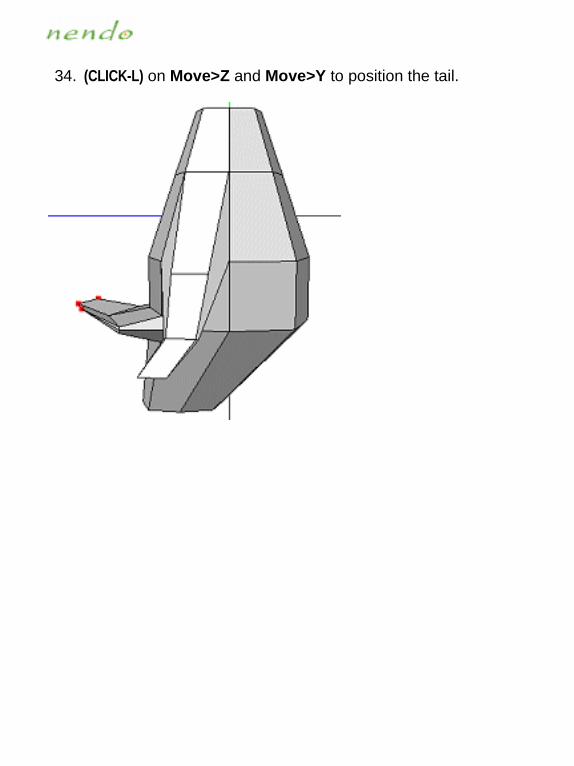
34. (CLICK-L) on Move>Z and Move>Y to position the tail.

([ORJOTM�ZNK�.KGJ35. Rotate the camera so that you can see the top of the model.

36. Select the edges that form a diamond on the top of the model, then (CLICK-L) on Dissolve to remove them.
37. Select the top face and use Extrude>Normal to pull it up.

38. (CLICK-L) on Rotate>X and tilt the face towards the front.

39. Repeat steps 37 and 38 so that the penguin looks like this:
40. With the face still highlighted, (CLICK-L) on Extrude>Z and pull the face out again.
41. Then, (CLICK-L) on Flatten>Z to flatten the face.

42. (CLICK-L) on Extrude>Normal and pull the flattened face out a tiny bit.
43. Rotate the camera so that you can see the front of the penguin.
44. Next, (CLICK-L) on Scale>Uniform to shrink the face.
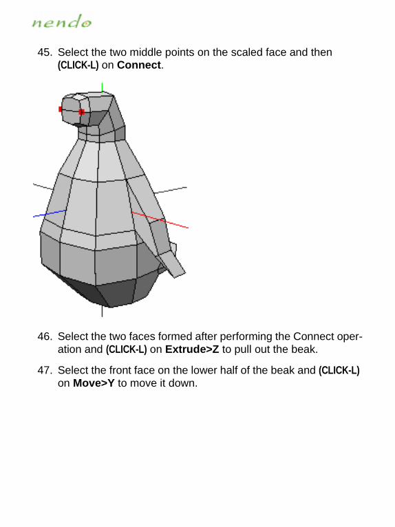
45. Select the two middle points on the scaled face and then (CLICK-L) on Connect.
46. Select the two faces formed after performing the Connect oper-ation and (CLICK-L) on Extrude>Z to pull out the beak.
47. Select the front face on the lower half of the beak and (CLICK-L) on Move>Y to move it down.

48. Select the front faces on the upper and lower half of the beak, then (CLICK-L) on Extrude>Z to pull them out a bit more.
49. Press the "space bar" hot key to clear your selection.
50. Select the front face on the bottom half of the beak and (CLICK-L) on Move>Z to move it back a bit.
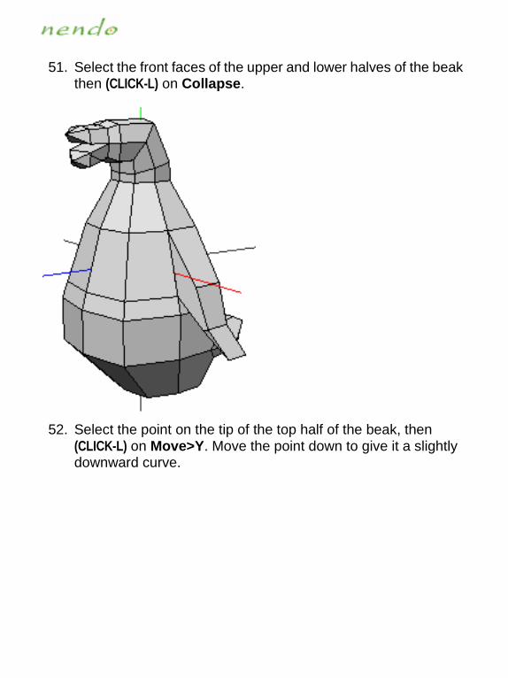
51. Select the front faces of the upper and lower halves of the beak then (CLICK-L) on Collapse.
52. Select the point on the tip of the top half of the beak, then (CLICK-L) on Move>Y. Move the point down to give it a slightly downward curve.

53. Now, select the point on the tip of the bottom half of the beak then (CLICK-L) on Move>Y to give it a slight upward curve.

54. Select the first loop of edges on both halves of the beak, then (CLICK-L) on Scale>X to shrink them.
NOTE...
Don’t forget to select the edges on the inside of the beak!
55. Move the camera so that you can see the top of the top beak.
56. Select the middle vertex on the top beak and (CLICK-L) on Move>Y to give the beak a bump.

57. Select the middle edge on the top of the head and (CLICK-L) on Move>Normal to round out his head.

)XKGZOTM�ZNK�2KMY�GTJ�,KKZ58. Rotate the camera so that you can see the bottom of the pen-
guin.

59. Select the edges that form the diamond, then (CLICK-L) on Dis-solve.
60. Select the two vertices shown below, then (CLICK-L) on Con-nect.
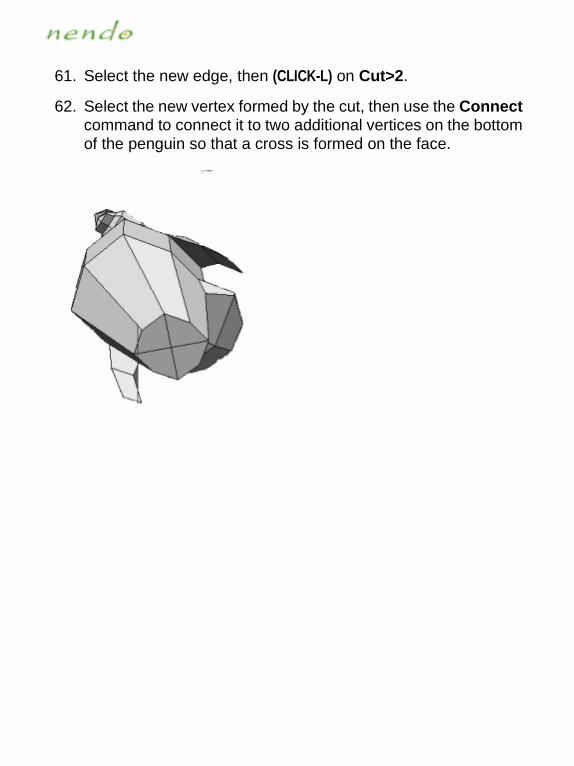
61. Select the new edge, then (CLICK-L) on Cut>2.
62. Select the new vertex formed by the cut, then use the Connect command to connect it to two additional vertices on the bottom of the penguin so that a cross is formed on the face.

63. Select the two faces that are closest to the rear of the penguin then (CLICK-L) on Move>Normal to round out the bottom of the penguin.

64. With these faces still selected, (CLICK-L) on Inset to inset faces that are slightly smaller than the currently selected ones. You control how far the faces are inset by moving the mouse left and right. When they are inset the correct amount, (CLICK-L) in the Model window.
65. The inset faces are now highlighted. (CLICK-L) on Move>Normal and pull the faces down to form the penguin’s legs.

66. (CLICK-L) on Extrude>Normal and pull the faces down again. These extrusions will form the feet.
67. Select all four edges across the front of the penguin’s feet and then (CLICK-L) on Cut>3.

68. Press the space bar to clear your selection.
69. Select the new vertices on the penguin’s feet formed by the Cut operation (shown below) and then (CLICK-L) on Connect to create edges between the vertical pairs of vertices.
When you have multiple vertices selected, Connect creates edges between the closest pairs of vertices.

70. Pick the faces formed by the Connect operation on the front of the feet and (CLICK-L) on Extrude>Z to pull the faces out to make the toes.
71. With the faces still selected, (CLICK-L) on Scale>Uniform to shrink the toes.

72. (CLICK-L) on View>Aim to aim the camera at the selected ele-ments.
NOTE...
You can also use the "a" hot key to aim the camera.
73. Select the outside toe on the left foot and (CLICK-L) on Move>Free to move it away from the other toes. Repeat this operation on the inside toe on the left foot and the corre-sponding toes on the right foot.
74. Select the front face on each toe, then (CLICK-L) on Extrude>Z and extrude the faces out a small amount.

75. (CLICK-L) on Move>Y to curl the toes up.
76. With the faces still highlighted, (CLICK-L) on Extrude>Z again.

77. (CLICK-L) on Collapse to collapse the faces.
78. (CLICK-L) on File>Save to save the penguin. In the dialog box that appears, navigate to the directory in which you want to save your penguin. Then, enter a name for the penguin (for example, Penguin) and (CLICK-L) on Save.
Your penguin model is now complete! In the next sections, we’ll show you how to add color to your penguin and create a higher-resolution version.

)URUXOTM�ZNK�6KTM[OTYou can color your penguin by painting or using the Apply Color command. In this section, we will use the Apply Color command to color the penguin. Apply Color assigns colors to vertices, edges, faces, and objects.
79. (CLICK-L) on Window>Show Object Info.
You use the Object Info window, to set the display options for individual objects. You can set any of the following options:
• Visibility
• Sensitivity
• Name
80. Make sure that Colors are toggled on. If they aren’t, then (CLICK-L) on View>Colors.
81. Select a dark gray with which to color the penguin. You do this with the Color Bar or with the Color Mixer:

■ To use the Color Bar:
• (CLICK-L) on a dark gray spot on the Color Bar. That color appears in the Current Color box next to the Color Bar.
■ To use the Color Mixer:
• (CLICK-L) on Window>Show Color Mixer, then (DRAG-L) the Color Picker Tool and the Brightness slider until the correct color appears in the Color/Solid Box in the Color Mixer window.
Color Picker Tool
Brightness Color Bar
• When the correct color is shown in the Current Color Box, (CLICK-L) on Add to Custom Colors to add the color. The new color will appear in the Custom Color Box.
• (CLICK-L) on OK. The color appears in the Current Color Box next to the Color Bar.
NOTE...
If you (DOUBLE-CLICK) on the Color Bar, the Color Mixer window opens.
82. Now that dark gray is the current color, select the penguin object and (CLICK-L) on Apply Color.

83. Press the space bar to clear your selection. The penguin is now dark gray.
84. Move the camera so that you have a good view of the beak.

85. Select the vertex on the end of both halves of the beak and then use the "f" hot key twice to select all of the faces on the beak.
86. With the faces selected, select an orange shade for the beak.
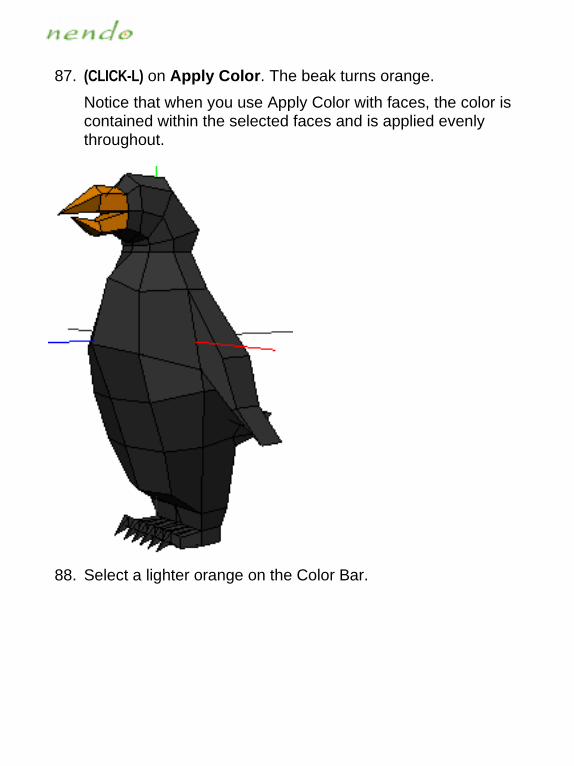
87. (CLICK-L) on Apply Color. The beak turns orange.
Notice that when you use Apply Color with faces, the color is contained within the selected faces and is applied evenly throughout.
88. Select a lighter orange on the Color Bar.

89. Select a few edges on the top and bottom halves of the beak and then (CLICK-L) on Apply Color to apply the lighter orange. This creates highlights on the beaks.
Color applied to edges, or edge color, is concentrated at the selected edges and fades out as you move away from that edge. The color is actually applied to the vertices on each end of the selected segments but only in the faces adjacent to the selected edges.
90. Select a red for the mouth’s interior.

91. Select all of the faces on the inside of the mouth, then (CLICK-L) on Apply Color to apply the red.

92. Move the camera so that you can easily select the faces on the penguin’s chest shown below.
93. Make white the current color and then (CLICK-L) on Apply Color to apply it to the penguin’s chest.
To make the color look a bit more natural, we can use the Ap-ply Color command on the vertices at the edge of the faces to blend the color into the rest of the body. Since the color is as-signed to vertices, this is known as vertex color. When you use vertex color, the color is applied to the vertices and the sur-
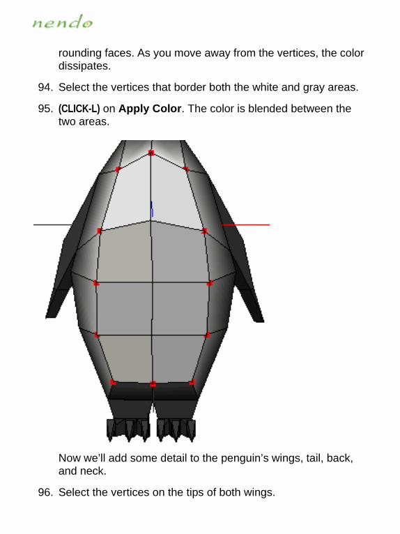
rounding faces. As you move away from the vertices, the color dissipates.
94. Select the vertices that border both the white and gray areas.
95. (CLICK-L) on Apply Color. The color is blended between the two areas.
Now we’ll add some detail to the penguin’s wings, tail, back, and neck.
96. Select the vertices on the tips of both wings.

97. (CLICK-L) on Select>Grow Selection to select the adjacent ver-tices.
NOTE...
You can also use the "+" hot key to select adjacent elements of the same type.
98. Select black from the Color Bar for the wings.
99. (CLICK-L) on Apply Color.
100. Push the space bar to clear your selection.

101. Use the same technique to make the tip of the tail black.
102. Select the edges down the middle of the penguin’s back.

103. (CLICK-L) on Apply Color. A black stripe appears down the penguin’s back.
104. Select a single row of edges around the penguin’s neck to form a ring.

105. (CLICK-L) on Apply Color. A black stripe appears around the penguin’s neck.
106. Select the vertices at the end of each of the penguin’s toes.
107. Use the "a" hot key to aim the camera at its toes.

108. Now, grow your selection using the "f" hot key until you have selected all of the faces on the feet.
109. Select an orange about the same as the orange on the beak and then (CLICK-L) on Apply Color. The feet are now colored orange.
110. Reselect the vertices on the ends of the penguin’s toes.
111. Select a black color.
112. (CLICK-L) on Apply Color to make the tips of the penguin’s toes black.
113. Now, your penguin has its basic color scheme.
114. Select the entire penguin and then (CLICK-L) on Smooth.
Smoothing creates a subdivided surface, giving the entire body a smoother appearance. Because smoothing is done by creat-ing subdivided surfaces, the colors assigned to the penguin’s edges and vertices are transferred to the new faces.

NOTE...
You can’t perform topological modeling operations, like smoothing, on a painted object.
115. Save your penguin.
NOTE...
You can also use the "CTRL-s" hot key to save your penguin.
f

6GOTZOTM�ZNK�6KTM[OTWhen you paint in Nendo, you apply colors and images onto your object using the Paint tools. Unlike the Apply Color command, which applies colors to points, edges, and faces, paint tools let you add de-tail wherever you want.
116. To enter Paint, (CLICK-L) on the Paint button.
When you open Paint, several changes occur in Nendo:
• Objects become flat shaded
• Outlining is turned off
• Neither the global axes or the ground plane are displayed
• Colors applied using the Apply Color command are copied into paint that is automatically applied to the object
• The Paint Toolbox appears:

Paintbrush ToolPencil Tool
Eraser ToolAirbrush Tool
Knife Tool
Lighten Brush Tool
Fill Tool
Smear Tool
Ellipse Tool
Bomb Tool
Line Tool
Pattern Tool
Hand Tool
Undo
Mask Tool
Shadow Brush Tool
Stamp Tool
Blur Tool
Color Picker Tool
Clone Tool
Rectangle Tool
Polygon Tool
Face Selection Tool
Reveal Tool
Inverse Mask Tool
Redo
Swatch

When using any of the tools in the toolbox, the angle at which you are painting and how close the camera is to your object af-fect how the paint is applied. It’s like working with a spray can, when you move close to or further from the object, or change the angle at which the paint hits.
117. (CLICK-L) on the Blur Tool in the Paint Toolbox.
We are going to blur the colors where the beak meets the pen-guin’s face and where its feet meet its legs.
118. (CLICK-R) in the Paint window to bring up the Brush Options menu.
You modify the size, softness, and opacity of brushes and tools in the Paint Toolbox with these options.
119. (CLICK-L) on Size>Small to modify the size of the Blur Tool.
120. Move the camera so that you have a good view of the area on the penguin where the beak meets the rest of the face.

121. (DRAG-L) the Blur Tool where the beak meets the face to brush out the line between the orange beak and black head.
122. Move the camera so that you can see the area where the pen-guin’s feet and legs meet.
123. (DRAG-L) the Blur Tool across the edges where the feet and legs meet.
124. (CLICK-L) on the Paintbrush Tool in the Paint Toolbox.

125. (CLICK-R) in the Paint window to bring up the Brush Options menu.
126. Then, (CLICK-L) on Size>Small to modify the size of the Paint-brush Tool.
127. Select a gray that is lighter than the gray used to color the pen-guin’s body. The color will appear in the Swatch in the Paint Toolbox.
128. On the white area of the penguin’s chest, paint small gray lines.
129. (CLICK-L) on the Smear Tool in the Paint Toolbox.

130. Use the Smear Tool to blend the gray lines with the white chest.
131. Move the camera so that you can see the side of the penguin’s head. We are going to paint eyes onto the penguin’s head.
132. (CLICK-L) on the Ellipse Tool in the Paint Toolbox.
133. Make white the current color.
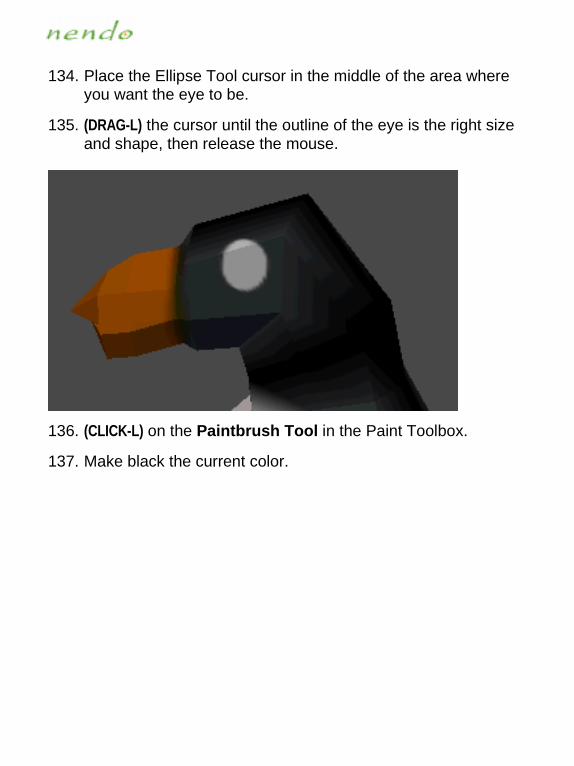
134. Place the Ellipse Tool cursor in the middle of the area where you want the eye to be.
135. (DRAG-L) the cursor until the outline of the eye is the right size and shape, then release the mouse.
136. (CLICK-L) on the Paintbrush Tool in the Paint Toolbox.
137. Make black the current color.

138. (CLICK-L) inside the white oval to place the penguin’s pupil.
139. (CLICK-L) on the Lighten Brush Tool in the Paint Toolbox.

140. (CLICK-L) in the middle of the pupil.
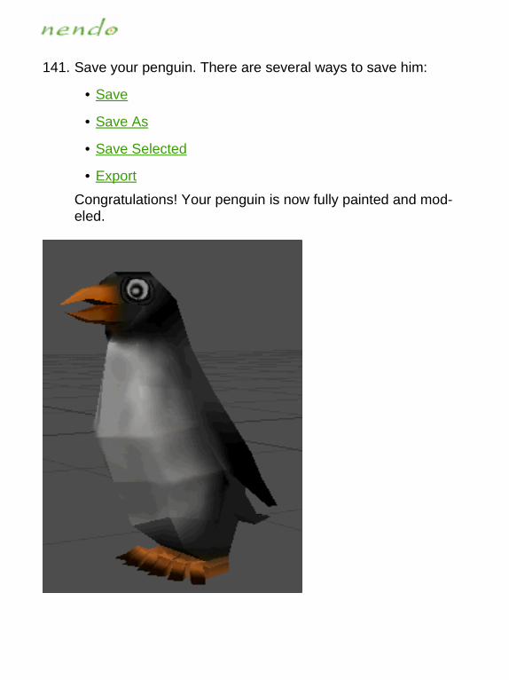
141. Save your penguin. There are several ways to save him:
• Save
• Save As
• Save Selected
• Export
Congratulations! Your penguin is now fully painted and mod-eled.

3KT[YThis section describes the commands in the menus located on the menubar:
Most of the commands on these menus also have keyboard short-cuts called hot keys. A summary of all hot keys is in:
Hot Keys
The File Menu
The Edit Menu
The View Menu
The Select Menu
The Window Menu
The Help Menu

:NK�,ORK�3KT[The File menu commands let you:
• Create new primitives
• Open previously saved objects
• Save objects to disk
• Take a snapshot of the current workspace
• Reload the object in its previously saved state
• Export objects to a different external file format
• Exit Nendo
Each of the options on the File menu are discussed in the following sections:
New Save Revert
Add Save As Import
Open Save Selected Export
Screen Capture Quit

4K]Removes all objects from your workspace and starts a new file. Use New if you want to clear your workspace and start a new project.
■ To remove all objects from your workspace:
• (CLICK-L) on File>New.

'JJAdds a new primitive or a previously saved object to your work-space. Primitives are standard geometric shapes from which you can build more complex objects.
■ To add a primitive:
• (CLICK-L) on File>Add, then select a primitive from the menu
NOTE...
You can also add a primitive if you (CLICK-R) in the Model window, then select a primitive from the menu that appears.
■ To load a previously saved object into the Model window:
• (CLICK-L) on File>Add>From File, then navigate to the file you wish to open. (CLICK-L) on OK to add the file.

5VKTRemoves all objects currently in your workspace and loads the se-lected files.
■ To open a file:
• (CLICK-L) on File>Open

9G\KSaves all of the objects in your workspace as a single file in Nendo’s native NDO format.
■ To save all objects in your workspace:
• (CLICK-L) on File>Save
NOTE...
The following characters cannot be used in filenames: ~ ‘ ! & * ( ) { } [ ] \ | ; : ’ " ? < > @ # $ % ^
9G\K�'YSaves all of the objects in your workspace as a single file with a new name and location in Nendo’s native NDO format.
■ To save objects with a new name and location:
• (CLICK-L) on File>Save As
NOTE...
The following characters cannot be used in filenames: ~ ‘ ! & * ( ) { } [ ] \ | ; : ’ " ? < > @ # $ % ^

9G\K�9KRKIZKJSaves the selected object or objects with a new name and location.
■ To save the selected objects with a new name and location:
• (CLICK-L) on File>Save selected
NOTE...
The following characters cannot be used in filenames: ~ ‘ ! & * ( ) { } [ ] \ | ; : ’ " ? < > @ # $ % ^

9IXKKT�)GVZ[XKTakes a snapshot of the current workspace and saves it as an im-age file.
■ To take a snapshot of the workspace:
1. (CLICK-L) on File>Screen Capture
2. In the file dialog that appears, navigate to the location in which you would like to save the screen capture, enter a file name and format, then (CLICK-L) on Save.

8K\KXZReloads the previously saved version of the file.
■ To revert an object to its last saved state:
• (CLICK-L) on File>Revert
NOTE...
You cannot undo the Revert command.
/SVUXZAdds objects in the following file formats to the current workspace:
• VRML 2.0 (.wrl)
• 3D Studio (.3ds)
• Wavefront (.obj)
• DirectX (.x)
• Game Exchange (.gof)
■ To import an object:
1. (CLICK-L) on File>Import
2. In the window that opens, navigate to the file you want to import.
3. Select the file and then (CLICK-L) on Open.
NOTE...
When importing files, Nendo first parses the file and then fixes the topology of the object. Depending upon the file, this process may be lengthy.

+^VUXZSaves objects in one of the following formats:
• VRML 2.0 (.wrl)
• Wavefront (.obj)
• 3D Studio (.3ds)
• DirectX (.x)
• Game Exchange (.gof)
• Monzoom 4.3 (.mon)
■ To export all objects as a single file:
1. (CLICK-L) on File>Export>All
2. In the window that opens, navigate to where you want to save the file, enter a file name and format, then (CLICK-L) on Save.
■ To export selected objects as a single file:
1. Select the objects you want to save
2. (CLICK-L) on File>Export>Selected
3. In the window that opens, navigate to where you want to save the file, enter a file name and format, then (CLICK-L) on Save.
NOTE...
Not all formats support all of the functionality of Nendo. For example, if your object has colors assigned to vertices and you export to 3D Studio (.3ds), Wavefront (.obj), or DirectX (.x), the vertex color information will not be exported.

<832�������]XR�/SVUXZImports the following data from VRML 2.0 (.wrl) files:
• Vertex coordinates
• Vertex color
• Object material
• Object name
• Textures
• UV coordinates
+^VUXZExports the following data to VRML 2.0 (.wrl) files:
• Vertex coordinates
• Vertex color
• Object material
• Object name
• Textures
• UV coordinates
�*�9Z[JOU����JY�/SVUXZImports the following data from 3D Studio (.3ds) files:
• Vertex coordinates
• Textures
• Base object color
• Object name
• UV coordinates
+^VUXZWhen you export to 3D Studio (.3ds), your objects will be triangulat-ed. Nendo exports the following data to 3D Studio (.3ds) files:
• Vertex coordinates
• Textures
• Base object color
• Object name
• UV coordinates

=G\KLXUTZ���UHP�/SVUXZImports the following data from Wavefront (.obj) files:
• Vertex coordinates
• Object color
• Object name
• Textures
• UV coordinates
+^VUXZExports the following data to Wavefront (.obj) files:
• Vertex coordinates
• Object color
• Object name
• Textures
• UV coordinates
-GSK�+^INGTMK���MUL�/SVUXZImports the following data from Nichimen Graphics’ Game Ex-change (.gof) files:
• Vertex coordinates
• Vertex color
• Object material
• Object name
• Textures
• UV coordinates
+^VUXZExports the following data to Nichimen Graphics’ Game Exchange (.gof) files:
• Vertex coordinates
• Vertex color
• Object material
• Object name
• Textures
• UV coordinates

*OXKIZ>���^�/SVUXZImports the following data from DirectX (.x) files:
• Vertex color
• Object material
• Object name
• Textures
• UV coordinates in ASCII format for Sun and PC; in Binary format for PC
+^VUXZExports the following data to DirectX (.x) files:
• Vertex color
• Vertex coordinates
• Object material
• Object name
• Textures
• UV coordinates in ASCII

3UT`UUS�������SUT�+^VUXZExports the following data to Monzoom 4.3 (.mon) files:
• Vertex coordinates
• Object color
• Object name

7[OZExits Nendo.
■ To quit Nendo:
• (CLICK-L) on File>Quit

:NK�+JOZ�3KT[The Edit menu commands let you:
• Undo the last action
• Delete objects
• Paint the object the current color
Each of the options on the Edit menu are discussed in the following sections:
Undo
Delete
Delete All
Paint All
;TJUReverses the last action performed in Nendo. In Model, if the last action was an undo, then Undo reverses the undo. In Paint, you can undo back to the last camera move.
■ To undo the last action:
• (CLICK-L) on Edit>Undo

*KRKZKDeletes the selected object or objects from your workspace.
■ To delete an object:
• Select the object you want to delete, then (CLICK-L) on Edit>Delete.
NOTE...
You can only delete objects when in Model, not in Paint.
*KRKZK�'RRDeletes all objects from your workspace.
■ To delete all of the objects from your workspace:
• (CLICK-L) on Edit>Delete All.
NOTE...
You can only delete objects when in Model, not in Paint.

6GOTZ�'RRIn Paint, paints the object the current color.
■ To paint the object the current color:
• (CLICK-L) on Edit>Paint All

:NK�<OK]�3KT[The View menu commands let you:
• Aim the camera at selected elements
• Reset the camera to its initial position
• Toggle display of the global axes or the ground plane in the Model window
• Turn smooth shading on and off
• Turn outline mode on and off
Each of the options on the View menu are discussed in the following sections:
Aim Wireframe All
Reset View Shade Selected
Ortho Camera Shade All
Ground Plane Workmode
Axes Colors
Wireframe Selected Textures
Hot Keys

'OSAims the camera at the selected element (or elements) in the Model window. If multiple elements are selected, the camera is aimed at the center of the collection.
■ To aim the camera:
• Select an element, then (CLICK-L) on View>Aim.

8KYKZ�<OK]Resets the camera to the initial camera view.
■ To reset the camera:
• (CLICK-L) on View>Reset View

5XZNU�)GSKXGToggles the camera between perspective and orthographic modes. In orthographic mode, all perspective is removed from the camera, so you can see the “true” geometry of an object. This is particularly useful when viewing an object along one of the major axes.
■ To toggle the camera between perspective and orthographic modes:
• (CLICK-L) on View>Ortho Camera

-XU[TJ�6RGTKDisplays a ground plane in the Model window. The ground plane in-tersects the Y axis where Y=0. It is a useful reference point when modeling.
■ To toggle display of the ground plane:
• (CLICK-L) on View>Ground Plane

'^KYDisplays the global axes. In order to make it easier for you to tell "which way is up," Nendo uses a Cartesian coordinate system rep-resented by a set of global axes. Positive Y (the green axis) repre-sents "up," positive X (the red axis) is "right," and positive Z (the blue axis) is "forward."
■ To display the global axes:
• (CLICK-L) on View>Axes

=OXKLXGSK�9KRKIZKJShows the selected objects in wireframe mode. In wireframe mode, only the object’s edges are visible (faces are not shaded).
■ To show the selected object in wireframe mode:
• (CLICK-L) on View>Wireframe Selected
NOTE...
When an object is displayed in wireframe mode, shading, colors, and paint assigned to the object are invisible.

=OXKLXGSK�'RRShows all of the objects in the workspace in wireframe mode. In wireframe mode, only the object’s edges are visible (faces are not shaded).
■ To show all of the objects in wireframe:
• (CLICK-L) on View>Wireframe All
NOTE...
When an object is displayed in wireframe mode, shading, colors, and paint assigned to the object are invisible.

9NGJK�9KRKIZKJShows the selected object in shaded mode.
■ To show the selected object in shaded mode:
• (CLICK-L) on View>Shade Selected

9NGJK�'RRShows all objects in the workspace in shaded mode.
■ To show all objects in shaded mode:
• (CLICK-L) on View>Shade All

=UXQSUJKWhen Workmode is toggled on, all objects in the workspace are dis-played using Gouraud shading, which creates smooth lighting tran-sitions between neighboring faces.
■ To show objects in workmode:
• (CLICK-L) on View>Workmode

)URUXYWhen Colors is toggled on, the colors and paint assigned to an ob-ject are visible.
■ To toggle the display of color:
• (CLICK-L) on View>Colors
NOTE...
Once an object is brought into Paint, colors assigned to the object using the Apply Color command are con-verted into paint.

:K^Z[XKYWhen Textures is toggled on, the images assigned to an object are visible.
■ To toggle the display of textures:
• (CLICK-L) on View>Textures
NOTE...
Once an object is brought into Paint, colors assigned to the object using the Apply Color command are con-verted into paint.
.UZ�1K_YLists all of the hot keys. A hot key is a key command that performs an action.
■ To show a list of the hot keys:
• (CLICK-L) on View>Hot Keys
For more information on hot keys, see Hot Keys.
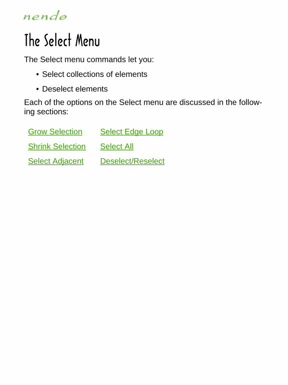
:NK�9KRKIZ�3KT[The Select menu commands let you:
• Select collections of elements
• Deselect elements
Each of the options on the Select menu are discussed in the follow-ing sections:
Grow Selection Select Edge Loop
Shrink Selection Select All
Select Adjacent Deselect/Reselect

-XU]�9KRKIZOUTFor the currently selected elements, selects neighboring elements of the same type.
■ To select adjacent elements of the same element type:
• Select an element, then (CLICK-L) on Select>Grow Selection.
Each of the adjacent elements of the same type is selected.
NOTE...
You can also use the "+" hot key to grow a selection.

9NXOTQ�9KRKIZOUTDeselects the outermost elements in a collection.
■ To deselect elements:
• (CLICK-L) on Select>Shrink Selection
The outermost elements in the collection are deselected.
NOTE...
You can also use the "-" hot key to shrink a selection.

9KRKIZ�'JPGIKTZSelects the vertices, edges, or faces adjacent to the selected ele-ments. The selected and adjacent elements do not have to be the same element type.
■ To select adjacent elements of a certain type:
• Select an element, then (CLICK-L) on one of the following:
Select>Select Adjacent>Vertices
Select>Select Adjacent>Edges
Select>Select Adjacent>Faces
All of the vertices, edges, or faces adjacent to the selected ele-ment are now selected. The originally selected element is de-selected.

9KRKIZ�+JMK�2UUVStarting with the selected edge, selects a "loop" of edges in either direction until a "Y" is encountered. It may be helpful to think of an edge loop as a contour line.
■ To select an edge loop:
1. Select an edge.
2. (CLICK-L) on Select>Select Edge Loop.

9KRKIZ�'RRSelects all of the vertices, edges, or faces on an object or all of the objects in the Model window.
■ To select all of an element type on an object:
• Select a vertex, edge, face, or object, then (CLICK-L) on one of the following:
Select>Select All>Vertices
Select>Select All>Edges
Select>Select All>Faces
Select>Select All>Objects

*KYKRKIZ�8KYKRKIZDeselects any selected elements.If no elements are selected, then the last selected elements are reselected.
■ To deselect or reselect elements:
• (CLICK-L) on Select>Deselect/Reselect
NOTE...
You can also press the space bar to deselect selected elements.

:NK�=OTJU]�3KT[The Window menu commands bring up palettes that let you:
• Set and view display parameters for individual objects
• Choose the color for paint and the Apply Color command
Each of the options on the Window menu are discussed in the fol-lowing sections:
Show Object Info
Show Color Mixer

9NU]�5HPKIZ�/TLUIn the Object Info window, you set the following parameters:
• Visibility
• Sensitivity
• Name
• Texture Size
-More-
Visibility
Sensitivity Name Texture Size

■ To change an object’s parameters:
1. (CLICK-L) on Window>Show Object Info .
2. (CLICK-L) on the icon of the parameter you want to change.
For example, to change the visibility of an object, (CLICK-L) on the Visibility Icon.
If you want to change the object’s name, (DOUBLE-CLICK) in the field and then enter a new name for the object.

<OYOHOROZ_Toggles an object’s visibility.
■ To toggle an object’s visibility:
• (CLICK-L) on Window>Show Object Info, then (CLICK-L) on the Visibility icon.
NOTE...
Invisible objects can’t be selected.

9KTYOZO\OZ_Insensitive objects are visible, but cannot be modified. This com-mand is useful if you have several objects close to each other, and want to modify one, but not another.
■ To toggle an object’s sensitivity:
• (CLICK-L) on Window>Show Object Info, then (CLICK-L) on the Sensitivity icon.

4GSKChanges the name of an object.
■ To change an object’s name:
• (CLICK-L) on Window>Show Object Info, then (DOUBLE-CLICK) in the Name field and enter the object’s new name
NOTE...
Changing the object’s name does not change the name of the file.
See also:
Combine

:K^Z[XK�9O`KSets the size of the texture used when you paint on the object. The bigger the texture map you use, the more detail you’ll be able to paint onto the surface of your object.
■ To set the size of the texture:
• (CLICK-L) on Window>Show Object Info, then select a texture size from the Texture size pop-up menu.
NOTE...
Larger textures have better resolution, but increase the object’s file size. In addition, some graphics cards do not support the display of larger texture maps, and may subsample the display.

9NU]�)URUX�3O^KXIn the Color Mixer window, you choose colors for the Apply Color command or with which to paint. The color can be either a basic or custom color.
■ To select a basic color:
1. (CLICK-L) on Window>Show Color Mixer.
2. (CLICK-L) on one of the Basic Colors. The color appears in the Color/Solid Box.
3. (CLICK-L) on Add to custom colors. The color appears in a Custom Colors Box. (CLICK-L) on OK to return to Nendo.
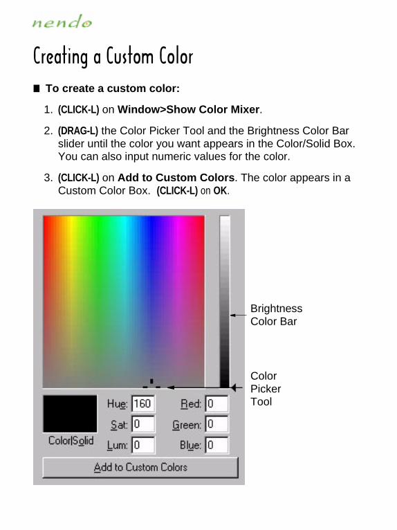
)XKGZOTM�G�)[YZUS�)URUX■ To create a custom color:
1. (CLICK-L) on Window>Show Color Mixer.
2. (DRAG-L) the Color Picker Tool and the Brightness Color Bar slider until the color you want appears in the Color/Solid Box. You can also input numeric values for the color.
3. (CLICK-L) on Add to Custom Colors. The color appears in a Custom Color Box. (CLICK-L) on OK.
Brightness Color Bar
Color Picker Tool

:NK�.KRV�3KT[The Help menu commands let you:
• Bring up the online help system
• Open the tutorial viewer
• Show the about screen
Each of the options on the Help menu are discussed in the following sections:
Help
How to
About

.KRVOpens Nendo’s online help system.
■ To open the help system:
• (CLICK-L) on Help>Help...
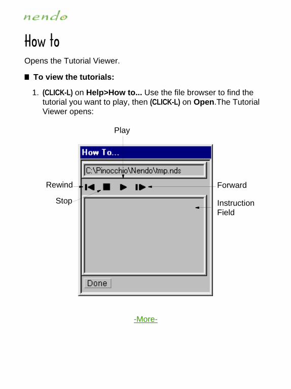
.U]�ZUOpens the Tutorial Viewer.
■ To view the tutorials:
1. (CLICK-L) on Help>How to... Use the file browser to find the tutorial you want to play, then (CLICK-L) on Open.The Tutorial Viewer opens:
-More-
Rewind
Stop
Play
Forward
Instruction Field

2. Push the Play button to start the tutorial.
The object you selected is built in the Model window. A descrip-tion of each step in the modeling process appears in the In-struction Field, if available.
While the tutorial is playing, you can also:
• (CLICK-L) on the Stop button to stop the tutorial.
• (CLICK-L) on the Rewind button to rewind the tutorial to the beginning
• (CLICK-L) on the Forward button to advance the tutorial to the next step
3. When you’re done, (CLICK-L) on the Done button to exit the Tutorial Viewer.

'HU[ZBrings up Nendo’s About window, which contains Nendo’s copyright information.
■ To open Nendo’s about window:
• (CLICK-L) on Help>About...
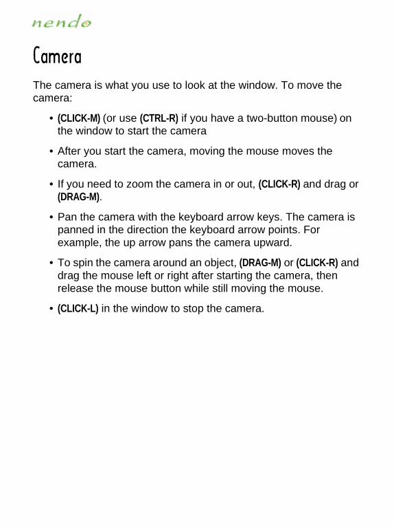
)GSKXGThe camera is what you use to look at the window. To move the camera:
• (CLICK-M) (or use (CTRL-R) if you have a two-button mouse) on the window to start the camera
• After you start the camera, moving the mouse moves the camera.
• If you need to zoom the camera in or out, (CLICK-R) and drag or (DRAG-M).
• Pan the camera with the keyboard arrow keys. The camera is panned in the direction the keyboard arrow points. For example, the up arrow pans the camera upward.
• To spin the camera around an object, (DRAG-M) or (CLICK-R) and drag the mouse left or right after starting the camera, then release the mouse button while still moving the mouse.
• (CLICK-L) in the window to stop the camera.

3UJKROTMModeling commands enable you to modify objects in Nendo. For more information on a particular command, (CLICK-L) on a link below:
Apply Color Delete Mirror
Bevel Dissolve Move
Bridge Extrude Clear Paint
Chipoff Region Extrude Region Plane Cut
Collapse Flatten Rotate
Combine Flip Scale
Connect Hardness Separate
Copy Inset Set Crease Angle
Cut Invert Smooth
Tighten

'VVR_�)URUXVertices, edges, faces, objects, and collections of these elements
Assigns color to the selected element.
■ To assign a color:
1. Select a color.
2. Select one or more elements, then (CLICK-R).
3. (CLICK-L) on Apply Color.
The current color is applied to the selected element.
NOTE...
For color to be visible, objects must be shaded and Color toggled on.

(K\KRVertices, edges, faces, and collections of these elements
Beveling an edge or vertex removes that element and replaces it with a face perpendicular to the normal of that element, "rounding" the corner. Beveling a face bevels each of its edges.
■ To bevel an element:
1. Select an element, then (CLICK-R).
2. (CLICK-L) on Bevel.
3. Move the mouse left and right to bevel the element interac-tively. (CLICK-L) when the element is beveled correctly.

(XOJMKCollection of two faces
Creates a tunnel or a bridge between two non-contiguous faces with the same number of vertices.
■ To bridge between two faces on the same object:
1. Select two faces with the same number of vertices, then (CLICK-R).
2. (CLICK-L) on Bridge. Either a tunnel or a bridge is created.
■ To bridge between two faces on different objects:
1. Select two faces whose normals are less than 180 degrees apart and that have the same number of vertices, then (CLICK-R).
2. (CLICK-L) on Bridge. A bridge is created.
Bridging between the two inside faces of the wheels
NOTE...
Once you bridge between two objects, the objects become a single object and cannot be separated.

)NOVULL�8KMOUTFaces or a collection of faces
Creates a duplicate, discrete copy of a selected face or collection of faces which can then be moved in the selected direction.
• Normal chips off the faces and moves them along its normal
• Free chips off the faces and moves them freely in any direction
• X,Y, Z chips off the faces and moves them along the selected axis
■ To chipoff faces:
1. Select a face or a collection of faces, then (CLICK-R).
2. (CLICK-L) on Chipoff Region, then select a direction to move the faces.
3. Move the mouse to move the faces. (CLICK-L) when done.

)RKGX�6GOTZObjects and collections of objects
Removes paint from an object so that you can perform topological modeling operations.
• Delete Paint Layer removes all paint from the object
• Paint Layer to Color converts all of the paint on the object into color and assigns it to the object’s vertices, edges, and faces.
■ To remove paint from an object:
1. Select an object, then (CLICK-R).
2. (CLICK-L) on Paint and select a method.
NOTE...
Color applied to an object using the Apply Color com-mand is converted into paint and applied to the object when you enter Paint. This paint must be converted back into color or removed from the object before you can perform any topological operations.

)URRGVYKVertices, edges, faces, and collections of these elements
Deletes the selected element while maintaining the closed surface of the object. Faces and edges collapse to a point; points collapse to a face.
■ To collapse an element:
1. Select an element, then (CLICK-R).
2. (CLICK-L) on Collapse.

)USHOTKCollections of objects
Combines multiple separate objects into a single object. Once com-bined, that object can then be manipulated as any other object.
■ To combine multiple objects:
1. Select the objects, then (CLICK-R).
2. (CLICK-L) on Combine.
The objects are combined into a single object.
NOTE...
Combined objects assume the name of the last object added to Nendo.

)UTTKIZCollection of vertices or edges
Creates a new edge that connects two vertices or the midpoints of two edges. If you have multiple vertices or edges selected, Connect creates edges between the closest pairs of vertices or edges.
■ To connect two elements:
1. Select a collection of vertices or edges, then (CLICK-R).
2. (CLICK-L) on Connect.
The vertices or the midpoint of the edges are connected by a new edge.

)UV_Objects and collections of objects
Duplicates the selected object.
■ To copy an object:
1. Select an object, then (CLICK-R).
2. (CLICK-L) on Copy.
3. Use the mouse to position the new object, then (CLICK-L) to place the object.

)[ZEdges and collections of edges
Cuts edges into a specified number of segments of equal length.
• 2, 3, 4, and 5 specify the number of segments
■ To cut one or more edges:
1. Select one or more edges, then (CLICK-R).
2. (CLICK-L) on Cut and then select the number of segments into which to cut the edges.

*KRKZKObjects and collections of objects
Deletes the selected object.
■ To delete an objects:
1. Select the objects, then (CLICK-R).
2. (CLICK-L) on Delete.
The objects are deleted.
NOTE...
You can only delete objects from Model, you cannot delete objects from Paint.

*OYYUR\KEdges and collections of edges
Eliminates the selected edge and turns the adjoining faces into one face.
■ To dissolve an edge:
1. Select an edge, then (CLICK-R).
2. (CLICK-L) on Dissolve.

+^ZX[JKVertices, faces, edges, and collections of these elements
Moves the element in the selected direction. Vertices and edges are beveled before moving.
• Normal extrudes the element and moves it along its normal
• Free extrudes the element and moves it freely in any direction
• X, Y, and Z extrude the element and move it along the speci-fied axis
■ To extrude an element:
1. Select an element, then (CLICK-R).
2. (CLICK-L) on Extrude and select a direction to extrude.
3. Move the mouse to extrude the element. (CLICK-L) when done.
See also: Extrude Region

+^ZX[JK�8KMOUTCollections of faces
Extrudes the selected faces as a region in the selected direction:
• Normal extrudes the faces as a region and moves them along the group’s normals
• Free extrudes the faces as a region and moves them freely
• X, Y, and Z extrude the selected faces as a region and moves them along the specified axis
NOTE...
Extrude Region behaves like Extrude on non-contig-uous faces in the collection.
■ To extrude a collection of faces as a region:
1. Select a group of contiguous faces, then (CLICK-R).
2. (CLICK-L) on Extrude Region and select a direction.
3. Move the mouse to extrude the region. (CLICK-L) when done.
See also: Extrude
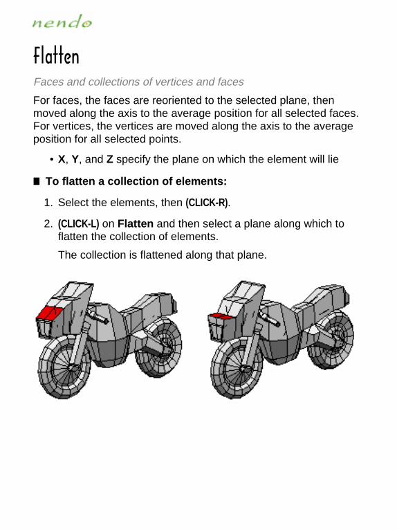
,RGZZKTFaces and collections of vertices and faces
For faces, the faces are reoriented to the selected plane, then moved along the axis to the average position for all selected faces. For vertices, the vertices are moved along the axis to the average position for all selected points.
• X, Y, and Z specify the plane on which the element will lie
■ To flatten a collection of elements:
1. Select the elements, then (CLICK-R).
2. (CLICK-L) on Flatten and then select a plane along which to flatten the collection of elements.
The collection is flattened along that plane.
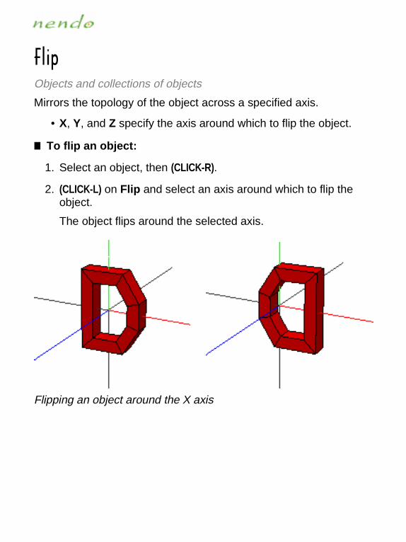
,ROVObjects and collections of objects
Mirrors the topology of the object across a specified axis.
• X, Y, and Z specify the axis around which to flip the object.
■ To flip an object:
1. Select an object, then (CLICK-R).
2. (CLICK-L) on Flip and select an axis around which to flip the object.
The object flips around the selected axis.
Flipping an object around the X axis

.GXJTKYYEdges and collections of edges
Sets the relative hardness of an edge. Hard edges retain their “shape” when you smooth an object.
• Soft is the default setting for an edge.
• Hard edges are thicker than soft edges and are unaffected by the smooth operation.
■ To set the hardness of an edge:
1. Select the edges, then (CLICK-R).
2. (CLICK-L) on Hardness, then select the hardness for the edges.
Smoothing an object with hard edges
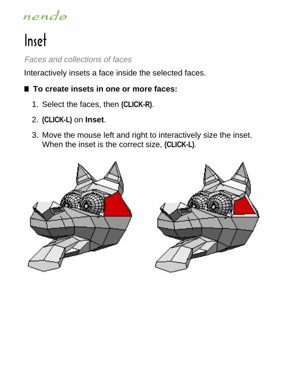
/TYKZFaces and collections of faces
Interactively insets a face inside the selected faces.
■ To create insets in one or more faces:
1. Select the faces, then (CLICK-R).
2. (CLICK-L) on Inset.
3. Move the mouse left and right to interactively size the inset. When the inset is the correct size, (CLICK-L).

/T\KXZObjects and collections of objects
Turns an object inside out, flipping its normals.
■ To invert an object:
1. Select an object, then (CLICK-R).
2. (CLICK-L) on Invert.
The object turns inside out.
NOTE...
This is useful when importing objects in other formats whose normals are flipped.
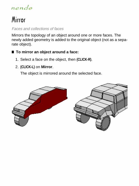
3OXXUXFaces and collections of faces
Mirrors the topology of an object around one or more faces. The newly added geometry is added to the original object (not as a sepa-rate object).
■ To mirror an object around a face:
1. Select a face on the object, then (CLICK-R).
2. (CLICK-L) on Mirror.
The object is mirrored around the selected face.

3U\KVertices, edges, faces, objects, and collections of these elements
Moves the selected elements in the selected direction:
• Normal moves the element along its individual normals
• Free moves the element freely
• X, Y, and Z move the selected elements along the specified axis
■ To move one or more elements:
1. Select the elements, then (CLICK-R).
2. (CLICK-L) on Move and select a direction.
3. Use the mouse to move the elements, then (CLICK-L).

6RGTK�)[ZObjects and collections of objects
Makes a cut through the object where it intersects the selected plane. If the object does not intersect the selected plane, then it will not be cut.
• X, Y, and Z specify the plane by which the object is cut
■ To chop an object:
1. Select an object, then (CLICK-R).
2. (CLICK-L) on Chop and select a plane to cut the object.
The faces that lie on the selected plane are cut..

8UZGZKVertices, edges, faces, objects, and collections of these elements
Rotates the element around a selected axis:
• Normal rotates the element around its individual normal
• Free rotates the element freely
• X, Y, and Z rotate the element around the specified axis; the center of collections rotate around the specified axis
■ To rotate one or more elements:
1. Select an element, then (CLICK-R).
2. (CLICK-L) on Rotate and select an axis of rotation.
3. Move the mouse to rotate the element, then (CLICK-L).
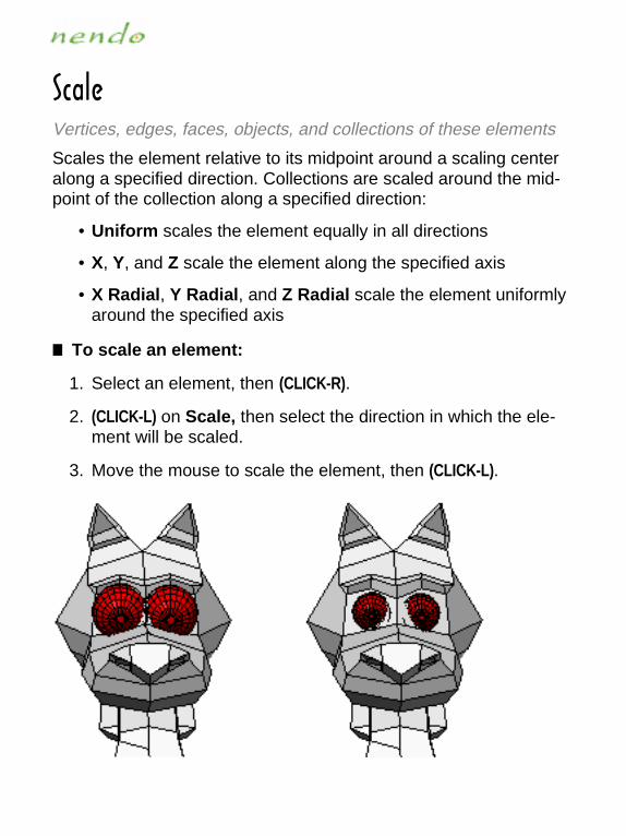
9IGRKVertices, edges, faces, objects, and collections of these elements
Scales the element relative to its midpoint around a scaling center along a specified direction. Collections are scaled around the mid-point of the collection along a specified direction:
• Uniform scales the element equally in all directions
• X, Y, and Z scale the element along the specified axis
• X Radial, Y Radial, and Z Radial scale the element uniformly around the specified axis
■ To scale an element:
1. Select an element, then (CLICK-R).
2. (CLICK-L) on Scale, then select the direction in which the ele-ment will be scaled.
3. Move the mouse to scale the element, then (CLICK-L).

9KVGXGZKObjects and collections of objects
Separates a combined object into its original components.
■ To separate a combined object:
1. Select a combined object, then (CLICK-R).
2. (CLICK-L) on Separate.
The combined object becomes separate objects.
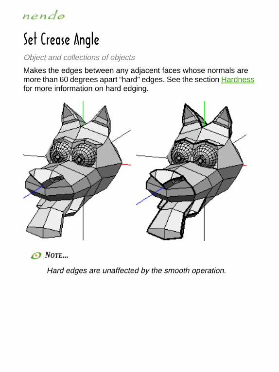
9KZ�)XKGYK�'TMRKObject and collections of objects
Makes the edges between any adjacent faces whose normals are more than 60 degrees apart “hard” edges. See the section Hardness for more information on hard edging.
NOTE...
Hard edges are unaffected by the smooth operation.

9SUUZNObjects and collections of objects
Gives an object a smoother appearance by cutting each face into many faces. The faces are subdivided by creating new vertices at the midpoints of each edge and at the geometric center of the face.
■ To smooth an object:
1. Select an object, then (CLICK-R).
2. (CLICK-L) on Smooth.
NOTE...
You cannot smooth objects that have been painted or hard edges.

:OMNZKTVertices, objects, and collections of these elements
Moves the selected elements to a point midway between its neigh-bors. The effect is to "pull in" points that stick out from the contour of the body. Once the element is at the midpoint of all its neighbors, no more tightening can occur. It may be helpful to think of this as a "smooth" of sorts which does not affect the topology of your object.
■ To tighten a set of vertices:
1. Select one or more vertices, then (CLICK-R).
2. (CLICK-L) on Tighten.
3. Move the mouse to tighten (or loosen) the vertices, then (CLICK-L).

6GOTZOTM
Paintbrush ToolPencil Tool
Eraser ToolAirbrush Tool
Lighten Brush Tool
Fill Tool
Smear Tool
Ellipse Tool
Bomb Tool
Line Tool
Pattern Tool
Hand Tool
Undo
Mask Tool
Shadow Brush Tool
Stamp Tool
Blur Tool
Color Picker Tool
Clone Tool
Rectangle Tool
Polygon Tool
Face Selection Tool
Reveal Tool
Inverse Mask Tool
Redo
Swatch
Knife Tool

'OXHX[YN�:UUR
Applies paint to the object using an Airbrush Tool.
■ To use the Airbrush Tool:
1. Select the color with which to paint.
2. (CLICK-L) on the Airbrush Tool icon, then (DRAG-L) to paint on the object.
Right, using the Airbrush Tool to add highlights to the Snake’s back
See also: Brush Options

(R[X�:UUR
Blurs the paint on the object.
■ To use Blur Tool:
1. (CLICK-L) on the Blur Tool icon.
2. (DRAG-L) the mouse over the area you want to blur.
Right, using the Blur Tool to blur the paint around the perimeter of the eye
See also: Brush Options

(USH�:UUR
The Bomb Tool fills the entire object with a selected color. The de-fault color is white.
■ To use the Bomb Tool:
1. (CLICK-L) on the Bomb Tool icon.
2. Select the Bomb color.
3. (CLICK-L) on the object you want to fill.
Using the Bomb Tool to color an entire object
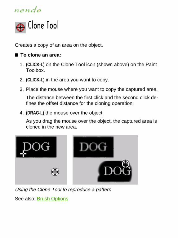
)RUTK�:UUR
Creates a copy of an area on the object.
■ To clone an area:
1. (CLICK-L) on the Clone Tool icon (shown above) on the Paint Toolbox.
2. (CLICK-L) in the area you want to copy.
3. Place the mouse where you want to copy the captured area.
The distance between the first click and the second click de-fines the offset distance for the cloning operation.
4. (DRAG-L) the mouse over the object.
As you drag the mouse over the object, the captured area is cloned in the new area.
Using the Clone Tool to reproduce a pattern
See also: Brush Options
)URUX�6OIQKX�:UUR
Selects the current color from the workspace.
■ To use the Color Picker Tool:
1. (CLICK-L) on the Color Picker Tool icon.
2. (CLICK-L) on a part of the object that has the color you want to use. That color becomes the current color and appears in the Swatch.

+RROVYK�:UUR
Draws a filled oval on the object.
■ To use the Ellipse Tool:
1. Select the color with which to draw and fill the oval.
2. (CLICK-L) on the Ellipse Tool icon.
3. (DRAG-L) the mouse until the oval is the right size, then release the mouse.
Using the Ellipse Tool to draw the pupil and the iris

+XGYKX�:UUR
Removes all paint from an area and paints it a selected color. The default color is white.
■ To use the Eraser Tool:
1. (CLICK-L) on the Eraser Tool icon.
2. Select the Eraser color.
3. (DRAG-L) the mouse over the area of the object you want to erase.
Using the Eraser Tool to remove paint
See also: Brush Options

,GIK�9KRKIZOUT�:UUR
Selects faces on objects.
■ To use the Face Selection Tool:
1. (CLICK-L) on the Face Selection Tool icon.
2. (CLICK-L) on a face to select it.
You can then use the Mask Tool to mask the faces you select-ed or the Inverse Mask Tool to mask the faces you didn’t.

,ORR�:UUR
The Fill Tool colors neighboring pixels that have the same color val-ue as the area you click. Note that only the visible area of an object is filled; an area of the same color that is facing away from the cam-era is not filled.
■ To use the Fill Tool:
1. Select the fill color.
2. (CLICK-L) on the Fill Tool icon.
3. (CLICK-L) in the area you want to fill.
Using the Fill Tool to fill a wheel
.GTJ�:UUR
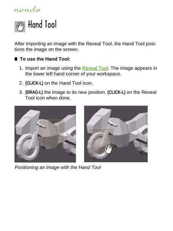
After importing an image with the Reveal Tool, the Hand Tool posi-tions the image on the screen.
■ To use the Hand Tool:
1. Import an image using the Reveal Tool. The image appears in the lower left hand corner of your workspace.
2. (CLICK-L) on the Hand Tool icon.
3. (DRAG-L) the image to its new position. (CLICK-L) on the Reveal Tool icon when done.
Positioning an image with the Hand Tool

/T\KXYK�3GYQ�:UUR
Creates a mask over non-selected areas of the object. A mask pre-vents painting in those areas.
■ To use the Inverse Mask Tool:
1. (CLICK-L) on the Face Selection Tool icon.
2. (CLICK-L) on each face on which you want to paint.
3. (CLICK-L) on the Mask Tool icon.
A mask is created over the faces you selected. You cannot paint on these faces.
4. (CLICK-L) on the Inverse Mask Tool icon (shown above) on the Paint Toolbar.
A mask is created over the faces you did not select. You can now paint on the faces you selected.
5. When you are done with the mask, (CLICK-L) on the Inverse Mask Tool icon to toggle it off.
Using the Inverse Mask Tool to prevent painting on non-selected areas of the motorcycle
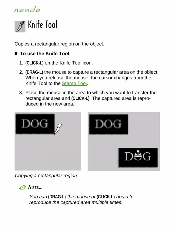
1TOLK�:UUR
Copies a rectangular region on the object.
■ To use the Knife Tool:
1. (CLICK-L) on the Knife Tool icon.
2. (DRAG-L) the mouse to capture a rectangular area on the object. When you release the mouse, the cursor changes from the Knife Tool to the Stamp Tool.
3. Place the mouse in the area to which you want to transfer the rectangular area and (CLICK-L). The captured area is repro-duced in the new area.
Copying a rectangular region
NOTE...
You can (DRAG-L) the mouse or (CLICK-L) again to reproduce the captured area multiple times.
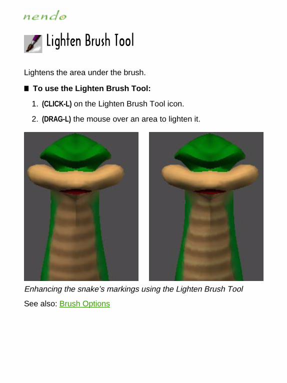
2OMNZKT�(X[YN�:UUR
Lightens the area under the brush.
■ To use the Lighten Brush Tool:
1. (CLICK-L) on the Lighten Brush Tool icon.
2. (DRAG-L) the mouse over an area to lighten it.
Enhancing the snake’s markings using the Lighten Brush Tool
See also: Brush Options

2OTK�:UUR
Draws a line on the object.
■ To use the Line Tool:
1. Select the color with which to draw.
2. (CLICK-L) on the Line Tool icon.
3. (DRAG-L) the mouse to draw the line.
Using the Line Tool to draw racing stripes
See also: Brush Options
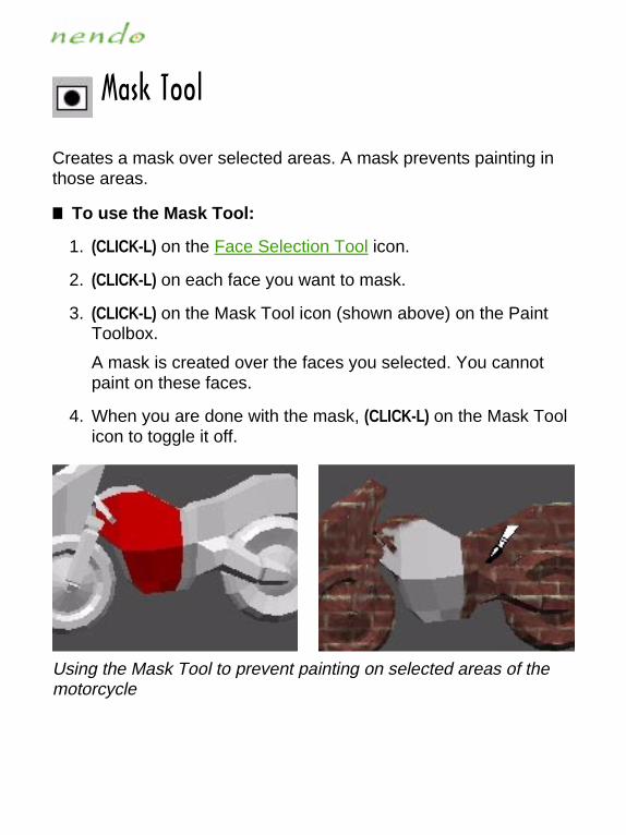
3GYQ�:UUR
Creates a mask over selected areas. A mask prevents painting in those areas.
■ To use the Mask Tool:
1. (CLICK-L) on the Face Selection Tool icon.
2. (CLICK-L) on each face you want to mask.
3. (CLICK-L) on the Mask Tool icon (shown above) on the Paint Toolbox.
A mask is created over the faces you selected. You cannot paint on these faces.
4. When you are done with the mask, (CLICK-L) on the Mask Tool icon to toggle it off.
Using the Mask Tool to prevent painting on selected areas of the motorcycle

6GOTZHX[YN�:UUR
Paints with brush strokes. This is the default brush in the toolbox.
■ To use the Paintbrush Tool:
1. Select a color with which to paint.
2. (CLICK-L) on the Paintbrush Tool icon.
3. (DRAG-L) the mouse over the area of the object you want to paint.
Using the Paintbrush Tool to paint the snake
See also: Brush Options

6GZZKXT�:UURImports images in one of the following formats: TIFF (.tif), PNG (.png), JPEG (.jpg or .jpeg), or PPM (.ppm). You can then paint with the imported image. The image will repeat endlessly, so images with seams (see below, right) appear tiled.
■ To use the Pattern Tool:
1. (CLICK-L) on the Pattern Tool icon.
2. Use the file browser to find the image you want to import, then (CLICK-L) on Open. The image appears in the Swatch.
3. (DRAG-L) the Paintbrush Tool, Pencil Tool, Airbrush Tool, or Stamp Tool to paint the imported image.
Left, painting with a seamless image; right, painting with a non-seamless image
NOTE...
In order to use the other Paint tools, you have to toggle the Pattern Tool off.

6KTIOR�:UUR
Draws a thin, hard-edged line on the object.
■ To use the Pencil Tool:
1. Select the color with which to draw.
2. (CLICK-L) on the Pencil Tool icon.
3. (DRAG-L) the mouse over the area of the object you want to paint.
Using the Pencil Tool
See also: Brush Options

6UR_MUT�:UUR
Draws a filled polygon on the object.
■ To use the Polygon Tool:
1. Select the color with which to draw and fill the polygon.
2. (CLICK-L) on the Polygon Tool icon.
3. (CLICK-L) on successive points to form the perimeter of the polygon. Click on the same point twice to close the polygon.
Using the Polygon Tool to create camouflage

8KIZGTMRK�:UUR
Draws a filled rectangle on the object.
■ To use the Rectangle Tool:
1. Select the color with which to draw and fill the rectangle.
2. (CLICK-L) on the Rectangle Tool icon.
3. (DRAG-L) the mouse until the rectangle is the right size, then release the mouse.
Using the Rectangle Tool

8KJU
In Paint, Redo undoes the last undo. You can use the Redo icon re-peatedly to reverse multiple undos. For example, if you undo the last five paint operations in Nendo, then you can redo all five or just the last three.
■ To undo the last undo:
• (CLICK-L) on the Redo icon
See also:
Undo
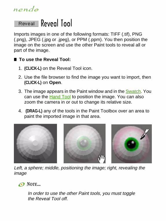
8K\KGR�:UURImports images in one of the following formats: TIFF (.tif), PNG (.png), JPEG (.jpg or .jpeg), or PPM (.ppm). You then position the image on the screen and use the other Paint tools to reveal all or part of the image.
■ To use the Reveal Tool:
1. (CLICK-L) on the Reveal Tool icon.
2. Use the file browser to find the image you want to import, then (CLICK-L) on Open.
3. The image appears in the Paint window and in the Swatch. You can use the Hand Tool to position the image. You can also zoom the camera in or out to change its relative size.
4. (DRAG-L) any of the tools in the Paint Toolbox over an area to paint the imported image in that area.
Left, a sphere; middle, positioning the image; right, revealing the image
NOTE...
In order to use the other Paint tools, you must toggle the Reveal Tool off.

9NGJU]�(X[YN�:UUR
Adds a nearly transparent black layer to the object. Use it to draw shadows on the object.
■ To use the Shadow Brush Tool:
1. (CLICK-L) on the Shadow Brush Tool icon, then (DRAG-L) to paint on the object.
Adding a shadow to the dog’s ear
See also: Brush Options

9SKGX�:UUR
Smears paint on the object, much as if you were fingerpainting.
■ To use the Smear Tool:
1. (CLICK-L) on the Smear Tool icon.
2. (DRAG-L) on the areas you want to smear.
Using the Smear Tool to blend
See also: Brush Options

9ZGSV�:UUR
Stamps an image onto the object.
■ To stamp an image:
1. (CLICK-L) on the Stamp Tool icon.
2. If an image is already loaded, it will appear in the Swatch. (CLICK-L) on the object where you want to stamp the image.
If an image isn’t loaded, use the file browser to find the image you want to open, then (CLICK-L) on Open. An outline appears around the Stamp Tool icon.
3. (CLICK-L) on the object where you want to stamp the image.
The image is stamped onto the object. You can also (DRAG-L) the mouse to stamp the image multiple times.
Left, original sphere; middle, positioning the Stamp Tool; right, after using the Stamp Tool
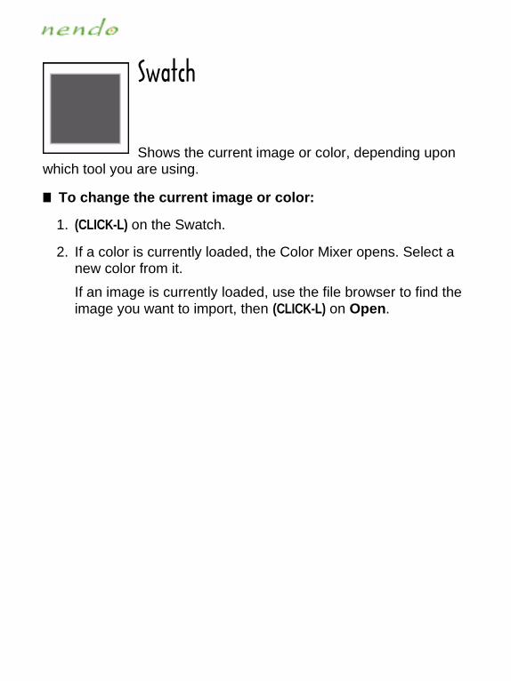
9]GZIN
Shows the current image or color, depending upon which tool you are using.
■ To change the current image or color:
1. (CLICK-L) on the Swatch.
2. If a color is currently loaded, the Color Mixer opens. Select a new color from it.
If an image is currently loaded, use the file browser to find the image you want to import, then (CLICK-L) on Open.

;TJU
Undo reverses the last Paint operation in Nendo.You can use the Undo icon repeatedly to reverse multiple actions.
■ To undo the last action:
• (CLICK-L) on the Undo icon.
NOTE...
Once you move the camera, you cannot undo any painting that was done prior to the camera move.

(X[YN�5VZOUTYYou can modify the parameters of the following tools and brushes:
■ To modify the tools and brushes in Paint:
• Select a tool, then (CLICK-R) and select the parameter you would like to modify:
Size
Softness
Opacity
NOTE...
Nendo remembers the settings that you make for each tool.
Airbrush Tool Line Tool
Blur Tool Paintbrush Tool
Bomb Tool Pencil Tool
Clone Tool Polygon Tool
Ellipse Tool Rectangle Tool
Eraser Tool Shadow Brush Tool
Lighten Brush Tool Smear Tool

5VGIOZ_Specifies the relative opacity (Most Transparent, Transparent, Medium, Opaque, or Most Opaque) of paint applied to the object.
■ To change the paint’s opacity:
1. Select a tool, then (CLICK-R).
2. (CLICK-L) on Opacity and select a setting.
From left: Most Transparent, Transparent, Medium, Opaque, and Most Opaque

9O`KSpecifies the relative thickness of the tool (Tiny, Small, Medium, Large or Huge).
■ To change tool size:
1. Select a tool, then (CLICK-R).
2. (CLICK-L) on Size and select a setting.
From left: Tiny, Small, Medium, Large, and Huge

9ULZTKYYSets the relative hardness or softness of the tool’s edge (Soft, Me-dium, or Hard).
■ To change a tool’s softness:
1. Select a tool, then (CLICK-R).
2. (CLICK-L) on Softness and select a setting.
From left: Soft, Medium, and Hard

:OVYThe following links contain information which you may find useful:
• Painting Objects with Lots of Faces
• Aiming the Camera When Painting

6GOTZOTM�5HPKIZY�]OZN�2UZY�UL�,GIKYIf you’re painting an object with a high number of faces, you may see spots or smearing when you paint. This is because all of the painting changes you make on an object are saved in one image.
If you know you are working on a complex model, try one of the fol-lowing:
• Increase the size of the texture map applied to the object.
NOTE...
Increasing the size of the texture map increases its resolution, but also increases the object’s file size. In addition, larger texture maps are not supported by all graphics cards.
• Break the object into smaller, separate objects (if possible) before you begin painting.
NOTE...
Breaking an object into separate objects uses more memory.

'OSOTM�ZNK�)GSKXG�=NKT�6GOTZOTMWhen painting, try to aim the camera directly at the faces you’re painting on. If the camera is not aimed directly at a face, the paint, which looks good from one angle, may, in fact, have streaked along other faces, as shown below.

-RUYYGX_The glossary defines terms in Nendo with which you may not be fa-miliar. (CLICK-L) on a letter to jump to that section of the glossary.
Numerics A C D E F G I N O S T V W X

Term Definition
Numerics
.3DS file 3D Studio file format. Nendo imports and exports .3DS files.
A
Axis A straight line defining some direction in 3D space. See Axes.

C
Camera The viewport through which you look at objects in Nendo.
Cartesian Coordinate System
A system of defining 3D space using a set of three global axes wherein X represents "right and left," Y represents "up and down," and Z represents "for-ward and backward." The orientation and position of any element can be expressed in relationship to the global center, where these three axes meet.
Cone A cone is a geometric primitive with a circular base that tapers to a vertex.
Contiguous Touching or connected in an unbroken sequence.
Term Definition
+Y
-Y
+Z
-Z
+X
-X

Cube A cube is a six-sided geometric primitive.
Cylinder A cylinder is a geometric primitive formed by rotat-ing a parallel line around a fixed line.
D
Dodecahe-dron
A dodecahedron is a twelve-sided polyhedron.
E
Edge An edge is one side of a face. Each edge is bound by two vertices.
Element There are four kinds of elements in Nendo: vertices, edges, faces and objects. You specify which type of element you want to modify by selecting the corre-sponding element button.
Term Definition

F
Face A face is one side of a polygonal object. Every face is bound by three or more edges.
G
Global Axes The three axes formed by the intersection of the X, Y, and Z planes.
.GOF files Nichimen Graphics file format. Nendo imports and exports .GOF files.
Grid A grid is a primitive formed by a network of uni-formly spaced horizontal and perpendicular lines.
Ground Plane
The ground plane, which intersects the Y axis where Y=0 is represented by a grid. It can be turned on and off using the Ground Plane com-mand under the View menu.
Term Definition

I
Icosahedron A geometric primitive with twenty sides.
Image Imported two dimensional image in TIFF, PNG, JPEG, or PPM format.
M
Mask A mask prevents painting in an area.
N
NDO files Nendo’s native file format.
Normals Vectors which describe the orientation of the selected element.
Term Definition

O
.OBJ files Wavefront file format. Nendo imports and exports .OBJ files.
Object Each model in Nendo is an object. An object is the smallest unit that can be saved from Nendo.
Octahedron An octahedron is an eight-sided polyhedron.
S
Sphere A sphere is a geometric primitive where every point on the surface is equidistant from the center.
Status Bar The Status Bar describes the screen element cur-rently under the mouse. For example, if you move the mouse over a command, you can see what the command does.
Term Definition
T
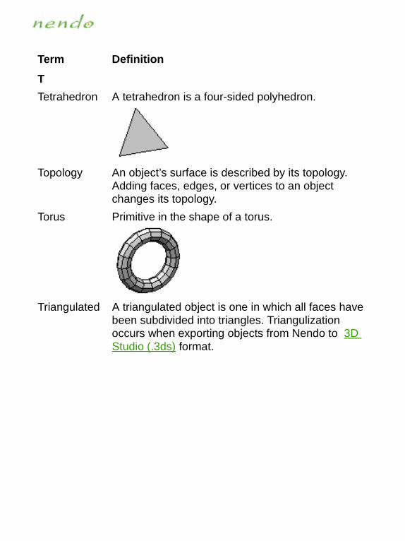
Tetrahedron A tetrahedron is a four-sided polyhedron.
Topology An object’s surface is described by its topology. Adding faces, edges, or vertices to an object changes its topology.
Torus Primitive in the shape of a torus.
Triangulated A triangulated object is one in which all faces have been subdivided into triangles. Triangulization occurs when exporting objects from Nendo to 3D Studio (.3ds) format.
Term Definition

V
Vertex or Vertices
A point where two or more edges intersect.
W
.WRL file VRML file format. Nendo imports and exports .WRL files.
X
.X file DirectX file format. Nendo exports .X files.
Term Definition

.UZ�1K_YA hot key is a key command that performs an action.
Command Hot Key Description
Grow Selection + Selects adjacent elements of the same element type.
Shrink Selection - Deselects the outermost ele-ments in a collection.
Display element count
? Displays the number of verti-ces, edges, and faces on the selected object(s) in a pop-up dialog.
Record a script { Start recording a tutorial.
Stop recording a script
} Stop recording a tutorial.
Workmode TAB key Toggle in to and out of work-mode.
Deselect/Reselect Spacebar Deselects all elements. If all elements are deselected, reselects the last selection.
Pan camera up Up arrow Moves the camera up while keeping it in the same plane.
Pan camera down Down arrow Moves the camera down while keeping it in the same plane.
Pan camera left Left arrow Moves the camera to the left while keeping it in the same plane.

Pan camera right Right arrow Moves the camera to the right while keeping it in the same plane.
Aim a Aims the camera at the selected element.
Makes objectssensitive
b Selects the Objects button.
Colors c Toggles the display of colors.
Repeats the last operation
d Repeats the last modeling operation performed
Select Adjacent e Selects all edges adjacent to the selected element. If no elements are selected, "e" selects the Edges button.
Select Adjacent f Selects all faces adjacent to the selected element. If no elements are selected, "f" selects the Faces button.
Show hot keys h Displays a list of hot keys.
Ortho Camera o Toggles orthographic mode on and off.
Open CTRL-o Loads a file after deleting other objects in Nendo.
Quit CTRL-q Exits Nendo.
Reset View r Resets the camera to the ini-tial camera view.
Command Hot Key Description

Shade Selected s Displays selected objects in shaded mode.
Shade All S Displays all objects in shaded mode.
Save CTRL-s Saves all of the currently loaded objects together in one file, using the .NDO format.
Textures t Toggles the display of tex-tures.
Select Adjacent v Selects all vertices adjacent to the selected element. If no elements are selected, "v" selects the Vertices button.
Wireframe Selected w Displays selected objects in wireframe mode.
Wireframe All W Displays all objects in wire-frame mode.
Align Camera +X x Aligns the camera with the X axis.
Align Camera -X SHIFT+x Aligns the camera with the -X axis.
Align Camera +Y y Aligns the camera with the Y axis.
Align Camera -Y SHIFT+y Aligns the camera with the -Y axis.
Align Camera Z z Aligns the camera with the Z axis.
Command Hot Key Description

Align Camera -Z SHIFT+z Aligns the camera with the -Z axis.
Undo CTRL-z Undoes the last action.
Command Hot Key Description

8KIUXJOTM�G�9IXOVZYou can record a script showing how to build an object using the "{" and "}" hot keys. Once recorded, the script can be played in the Nendo workspace using the How to command.
■ To record a script:
1. Press the "{" hot key.
2. In the Record Tutorial dialog box that appears, navigate to the location where you want to save the recorded script and enter a script name, then (CLICK-L) on Ok. This enters record mode.
NOTE...
All objects in the workspace are deleted when you enter record mode. Make sure to save your work before you start recording a script.
3. Build the object.
NOTE...
While Nendo is in record mode, all actions in the work-space are recorded.
4. When the object is complete, press the "}" hot key to stop recording.
To play the script you just recorded, see How to.

'HU[Z�.KRVNendo’s online help system is delivered in PDF format. This section gives details on how to access information in the online help system. (CLICK-L) on a link below for more information:
Navigating Nendo’s Help
Printing Out Help

4G\OMGZOTM�4KTJU«Y�.KRVNendo’s online help is delivered in PDF format. You can navigate through it using:
• Links
• Bookmarks
• Toolbar buttons
. For example:
• (CLICK-L) on a green link or a bookmark topic to jump to that location.
• (CLICK-L) on the Previous View button to return to the previous page.
• (CLICK-L) on the First Page button or on Home in the book-marks to return to the home page.
You can also (CLICK-R) on the help screen to display a handy naviga-tion menu.
For more information on using Acrobat Reader:
• (CLICK-L) on Help>Reader Online Guide inside the Help window.
Previous View
First Page

6XOTZOTM�5[Z�.KRVIf you want to print out any part of Nendo’s help:
1. (CLICK-L) on File>Print.
A dialog box appears.
2. Choose to print all the pages, or only a certain range of pages, then (CLICK-L) on Print.
The selected pages print.

/TJK^4[SKXOIY3D Studio (.3ds)
exporting 87importing 87
3DS filesexporting 86importing 87
'About command 132Add command 77Aim command 99
hot key 208Airbrush Tool 164Apply Color command 135Axes
displaying 103
(Bevel command 136Blur Tool 165Bridge command 137button
Paint 64buttons
Edges 6Faces 6Free 6Objects 6Vertices 6
)camera

aiming 99moving 7resetting to initial view 100spinning 7, 133stopping movement 7, 133zooming 7, 133
Chip Off command 140Chop command 140Clear Selection command 118
hot key 207Clone Tool 167Collapse command 140color
Apply Color command 135choosing 126creating a custom color 127
Color Picker Tool 168Colors 109Combine command 141Cone 200Connect command 142Copy command 143Cube 201Cut command 144Cylinder 201
*Delete All command 96Delete command 95, 145DirectX (.x)
exporting 90Dissolve command 146Dodecahedron 201

+edge color 54Edge Loop 116Edit Menu 93elements
deselectinglist of ways to 9, 118using Clear Selection command 118using Shrink Selection command 114
selectingadjacent elements of any type 115adjacent elements of same type 113all of an element type on an object 117
Ellipse Tool 169Erase Texture command 97Eraser Tool 170Export command 85exporting
3D Studio (.3ds) 87DirectX (.x) 90Game Exchange (.gof) 89VRML 2.0 (.wrl) 86Wavefront (.obj) 88
Extrude command 147Extrude Region command 148
,face color 53Face Selection Tool 171File Menu 75filenames
disallowed characters 79Fill Tool 172Flatten command 149
Flip command 150
-Game Exchange (.gof)
exporting 89importing 89
GOF filesimporting and exporting 89
Grid 202Grow Selection command 113
hot key 207
.Hand Tool 173Help Menu 128Help System 129Help system
accessing 129navigating 213printing 214
highlighting 7Hot Key 111, 207Hot Keys 207
Aim command 208Camera 209Grow Selection command 207Objects button 208Open command 208Outlines 208Quit command 208Save command 209Select Adjacent command 208, 209Shrink Selection command 207Smooth Shaded command 209Undo 210

How to command 130
/Icosahedron 203Import command 84importing
3D Studio (.3ds) 87Game Exchange (.gof) 89VRML 2.0 (.wrl) 86Wavefront (.obj) 88
Inset command 152Inverse Mask Tool 174Invert command 152
1Knife Tool 175
2Lighten Brush Tool 176Line Tool 177
3Mask Tool 178Menu commands 74Mirror command 154Modeling commands 134Move command 155
4New command 76
5OBJ files
exporting 88importing 88
objectschanging parameters 121

colors and textures 109, 110sensitivity 123visibility 122
Octahedron 204Opacity 192Open command 78Outlines
displaying objects with 104, 105hot key 208
6Paint Tools 163
Airbrush Tool 164Blur Tool 165Clone Tool 167Color Picker Tool 168Ellipse Tool 169Eraser Tool 170Face Selection Tool 171Fill Tool 172Hand Tool 173Inverse Mask Tool 174Knife Tool 175Lighten Brush Tool 176Line Tool 177Mask Tool 178Paintbrush Tool 179parameters
opacity 192size 193softness 194
Pattern Tool 180Pencil Tool 181Polygon Tool 182Rectangle Tool 183

Redo 184Reveal Tool 185Shadow Brush Tool 186Smear Tool 187Stamp Tool 188Swatch 189Undo 190
Paintbrush Tool 179Pattern Tool 180Pencil Tool 181Plane Cut command 156Polygon Tool 182primitives
adding 77
7Quit command 92
hot key 208
8Redo 184Reset View command 100Reveal Tool 185Revert command 83Rotate command 157
9Save As command 80Save command 79
hot key 209Save Selected command 81Scale command 158Script 211Select Adjacent command 115
hot key 208Select All command 117

Select Menu 112selecting
elements 7adjacent elements of any type 115adjacent elements of same type 113all of an element type on an object 117
Sensitivitytoggling 123
Separate command 159Shadow Brush Tool 186Show Object Info command 120Shrink Selection command 114
hot key 207Size 193Smear Tool 187Smooth command 161Smooth Shaded command
hot key 209Smooth Shading
displaying objects with 104Softness 194Sphere 204Stamp Tool 188Status Bar 7Swatch 189
:Tetrahedron 205Texture 110Tighten command 162Tips 195Toolbox 163Torus 205tutorials
viewing 130

;Undo
hot key 210in Model 94in Paint 190
<vertex color 56View Menu 98Visibility
toggling 122VRML 2.0 (.wrl)
exporting 86importing 86
=Wavefront (.obj)
exporting 88importing 88
Window Menu 119Wireframe
hot key 209Workmode 108WRL files
exporting 86importing 86
>X files
exporting 90