Embed Size (px)
Citation preview

5G IoT-based Geohazard Monitoring and EarlyWarning System and its ApplicationZhaohua Li
Yango UniversityDawei Liu ( [email protected] )
Beihang UniversityXiaokun Sun
China University of Mining and Technology - Beijing CampusWang Peng
National Defense University
Research
Keywords: geological disasters, 5G communication, IoT, monitoring and early warning, GNSS
Posted Date: April 28th, 2021
DOI: https://doi.org/10.21203/rs.3.rs-432202/v1
License: This work is licensed under a Creative Commons Attribution 4.0 International License. Read Full License
Version of Record: A version of this preprint was published at EURASIP Journal on WirelessCommunications and Networking on July 28th, 2021. See the published version athttps://doi.org/10.1186/s13638-021-02033-y.

5G IoT-based Geohazard Monitoring and Early Warning Sys- 1
tem and its Application 2
LI Zhaohua1,3, LIU Dawei2, 3*, SUN Xiaokun4,Peng Wang5 3
1 Yango University, School of Civil Engineering, Fuzhou, 350015 4 2 Beihang University, School of Electronic Information Engineering, Beijing, 100191 5
3 Yunnan Innovation Institute·BUAA, Kunming , 650233 6 4 China University of Mining and Technology (Beijing), School of Mechanics and Construction Engineering, Beijing, 100083 7
5 National Defense University of PLA ,Joint War College, Beijing, 100091 8 * Correspondence: [email protected] 9
Abstract: With the expansion of human production activities, geological disasters caused by slope instability are occuring more 10
frequently. Hence, the research on effective monitoring and forecasting of the geotechnical stability of slopes is of great significance 11
for the prevention and mitigation of slope geological disasters. In this study, a landslide monitoring and early warning system based 12
on 5G Internet of Things (IoT) technology is introduced. The system monitors important indicators such as three-dimensional 13
surface displacement, rainfall, and ground cracks using Global Navigation Satellite System (GNSS) equipment and various IoT 14
sensors deployed on site. The key monitoring data are transmitted and displayed by 5G communication and advanced data 15
visualization technologies. An early warning guideline is established by combining the surface deformation rate-time curve 16
according to a four-level early warning method as well as embedded vector maps such as the topographic and geomorphological 17
remote sensing map of the monitoring area, the geological section map, and the monitoring point distribution map. The system has 18
the functions of accurate acquisition, rapid transmission, automatic search, and comprehensive analysis, and is applied to the study 19
of creep slopes of the Lianhe terraces in Youxi County, Fujian Province, with remarkable results. 20
Keywords: geological disasters; 5G communication; IoT; monitoring and early warning; GNSS 21
22
1. Introduction 23
24
Landslides and other geological disasters are increasingly becoming a key issue worldwide [1-5], and China is one 25
of the countries in the world that are more seriously affected by geological disasters. Geological disasters involve 26
complex geological conditions, the geographical environment, large spatiotemporal differences in climate, and many 27
hidden and widely distributed geological hazards, which are destructive and occur suddenly. As a result of both nat- 28
ural events and human activities, especially the rapid development of society, the economy, and cities in recent years, 29
destructive geological disasters are occurring more frequently. This causes significant impact and damage to the social 30
and economic development and the safety of people’s lives and properties, directly threatening the ecological envi- 31
ronment on which human beings depend. According to relevant statistics, at least 400 cities, counties, districts, towns, 32
and more than 10,000 villages in China are threatened by various types of geological disasters, encompassing a total 33
area of 1,735,200 square kilometers and accounting for 18.10% of the total land area of China. Examples include the six 34
satiated loess landslides induced by continuous rainfall on August 21, 1981 [6], loess mudflow landslides caused by 35
agricultural irrigation in Hefangtai [7], high-speed loess landslides induced by irrigation in Huaxian County, Shaanxi 36
in 2006 [8], Donghekou landslides induced by the Wenchuan earthquake in 2008 [10], high-speed remote landslides 37
that killed 46 people in Zhenxiong, Yunnan in 2013 [9,11, 12], and the runoff landslide in 2015 at the sludge receiving 38
site in Guangming New District, Shenzhen [13-15]. With the rapid economic development in recent years and the high 39
population density in China, each occurrence of a geological disaster may result in great loss of life and property to the 40
disaster-affected area. Therefore, it is of high practical application and educational value to carry out monitoring, early 41
warning, and risk assessment of geological disasters on a continuous basis and to establish an integrated 42
all-year-round monitoring, early warning, and risk assessment system. 43
Owing to equipment limitations in the early days, monitoring of geological disasters such as landslides was 44
mainly based on the manual observation of surface change characteristics and anomalies in groundwater and the 45

surrounding flora and fauna to determine the likelihood of an occurrence by inference [16, 17]. Later, with the devel- 46
opment of technological, conventional instruments of surface displacement monitoring, including total station, theod- 47
olite, level gauge, GPS monitoring, the newly developed GPS mobile phone monitoring, and Interferometric Synthetic 48
Aperture Radar (InSAR) technology, new instruments have gradually been utilized [18-22]. Currently, Global Naviga- 49
tion Satellite System (GNSS) monitoring methods based on point data acquisition and the space-borne and discontin- 50
uous ground-based inSAR techniques based on surface data acquisition are widely used to monitor large-scale land- 51
slides, and have also resulted in great progress in landslide monitoring and prediction [23-25]. Recently, along with the 52
rapid development of 5G communication technology, a novel monitoring and prediction system based on 5G-IoT was 53
developed and applied in a slope with long-term creep located in a terrace field. 54
This paper describes in detail this landslide monitoring and early warning system based on 5G-IoT technology. 55
The system monitors important indicators such as three-dimensional surface displacement, rainfall, and ground cracks 56
through GNSS equipment and various IoT sensors deployed on site, transmitting key monitoring data with 5G 57
communication technology, which are displayed with advanced data visualization technology. An early warning 58
guideline is established in accordance with a four-level early warning method by combining the surface deformation 59
rate-time curve as well as embedded vector maps such as topographic and geomorphological remote sensing maps of 60
the monitoring area, the geological section map, and the monitoring point distribution map. The system has the 61
functions of accurate acquisition, rapid transmission, automatic search, and comprehensive analysis. This paper is 62
divided into four sections. The second section gives a detailed introduction of the geo-meteorological and 63
hydrogeological conditions at the pilot site as well as the current situation of the slow creeping terrace slope. The third 64
section introduces the new monitoring and early warning system of geological disasters and its application in this 65
slope. The fourth section presents a brief summary of the study. 66
67
2. Methods/Experimental 68
2.1 Background of the Youxi Terraces Landslide Area 69
Youxi County is located south of the 26th parallel north and about 100 km east of the East China Sea, with a humid 70
mid-subtropical monsoon climate. Its summer is warm/hot, winter is cool/chilly, spring and summer are rainy, with 71
abundant precipitation. The average annual precipitation is between 1500 mm and 1750 mm, with extremely uneven 72
rainfall throughout the year, including many typhoons and rainstorms from May to August, which is the main flood 73
season. 74
Lianhe Township of Youxi County is surrounded by mountains, with an elevation of 260–1137.6m, and a 75
medium-low hilly landform. The relative elevation difference is 877.6m, and the slope has a gradient of 25-45°. The 76
mountainous terrain is high with steep topography and sharp gully cutting. According to the regional 1/50,000-scale 77
geological survey report (G50E010017), the fold structures developed in the area of Lianhe Township, Youxi County, 78
are mainly located in the Nanping-Yuxi compound syncline, with the axis located in the area of Xiqin, pointing in the 79
20-30° northeast direction. The area is composed mainly of presinian strata, with a gentle dip of about 30° in the axis of 80
the rock layer, while the flank can reach 50-60°. The secondary fold structures are developed in the axial part of the 81
compound syncline, and are parallelly arranged in the northeast direction. The fault structures in the area include 82
mainly two groups, the north-northeast fault structure of Baizhangji in Wencheng County and the north-west fault 83
structure of Dingdi in the highlands, with the former being the main fault structure. These two groups of fault 84
structures are large in scale, generally extending up to tens of kilometers, cutting deep into different tectonic layers. In 85
the fault structures, extrusion, rushing zones, and conglomerate are normally distributed, while silicification, 86
chloritization, and other alterations are generally observed with the development of small fractures. The Youxi Lianhe 87
terraces are located at the intersection of these two fault structures, with fragmented and unstable rock layers. 88
89
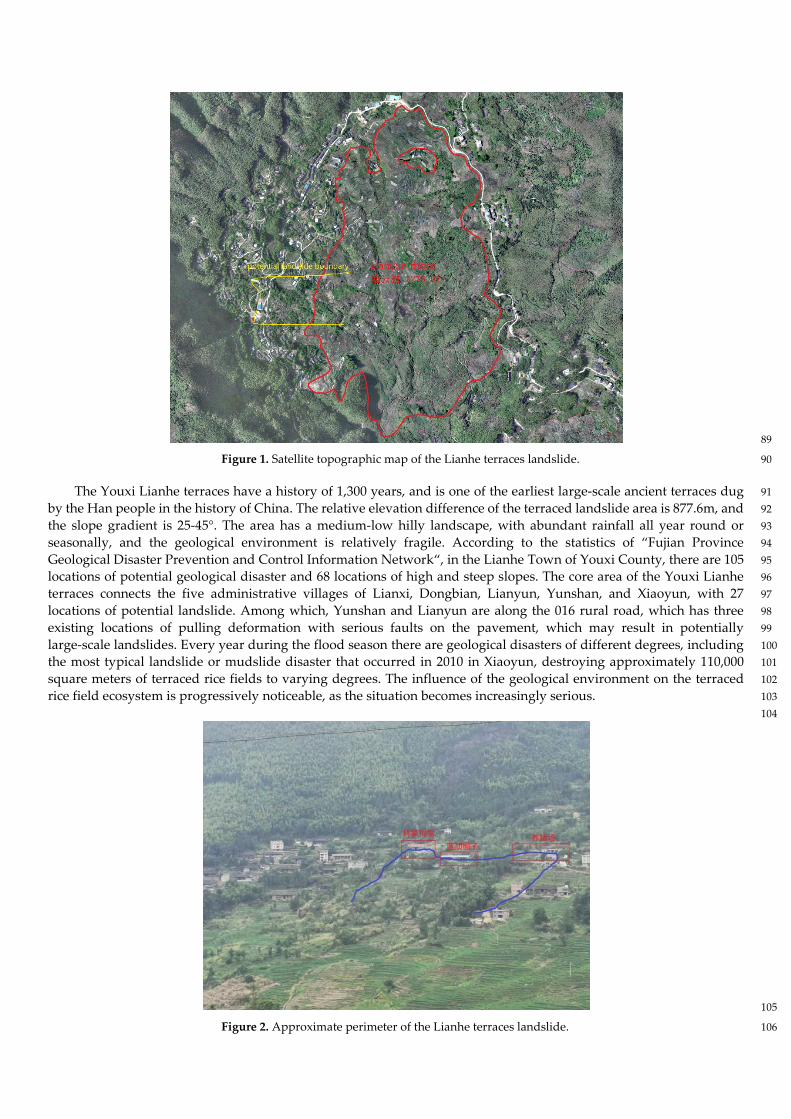
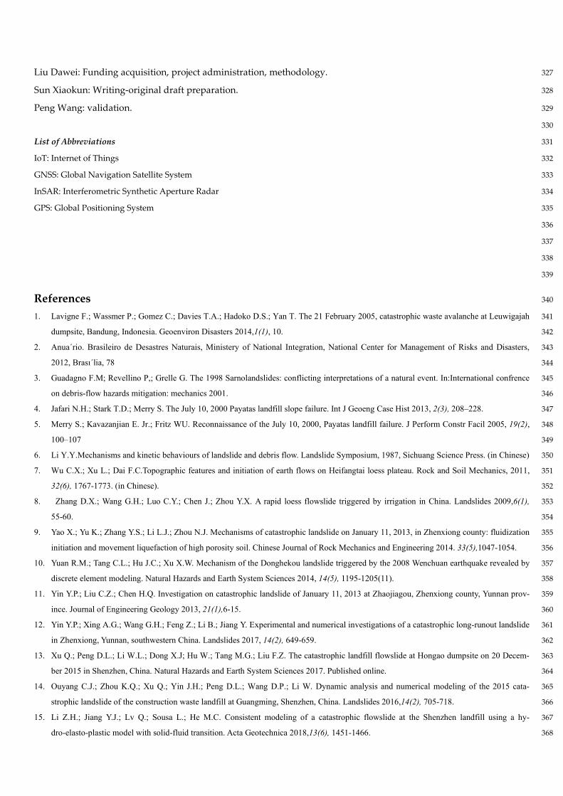
Figure 1. Satellite topographic map of the Lianhe terraces landslide. 90
The Youxi Lianhe terraces have a history of 1,300 years, and is one of the earliest large-scale ancient terraces dug 91
by the Han people in the history of China. The relative elevation difference of the terraced landslide area is 877.6m, and 92
the slope gradient is 25-45°. The area has a medium-low hilly landscape, with abundant rainfall all year round or 93
seasonally, and the geological environment is relatively fragile. According to the statistics of “Fujian Province 94
Geological Disaster Prevention and Control Information Network“, in the Lianhe Town of Youxi County, there are 105 95
locations of potential geological disaster and 68 locations of high and steep slopes. The core area of the Youxi Lianhe 96
terraces connects the five administrative villages of Lianxi, Dongbian, Lianyun, Yunshan, and Xiaoyun, with 27 97
locations of potential landslide. Among which, Yunshan and Lianyun are along the 016 rural road, which has three 98
existing locations of pulling deformation with serious faults on the pavement, which may result in potentially 99
large-scale landslides. Every year during the flood season there are geological disasters of different degrees, including 100
the most typical landslide or mudslide disaster that occurred in 2010 in Xiaoyun, destroying approximately 110,000 101
square meters of terraced rice fields to varying degrees. The influence of the geological environment on the terraced 102
rice field ecosystem is progressively noticeable, as the situation becomes increasingly serious. 103
104
105
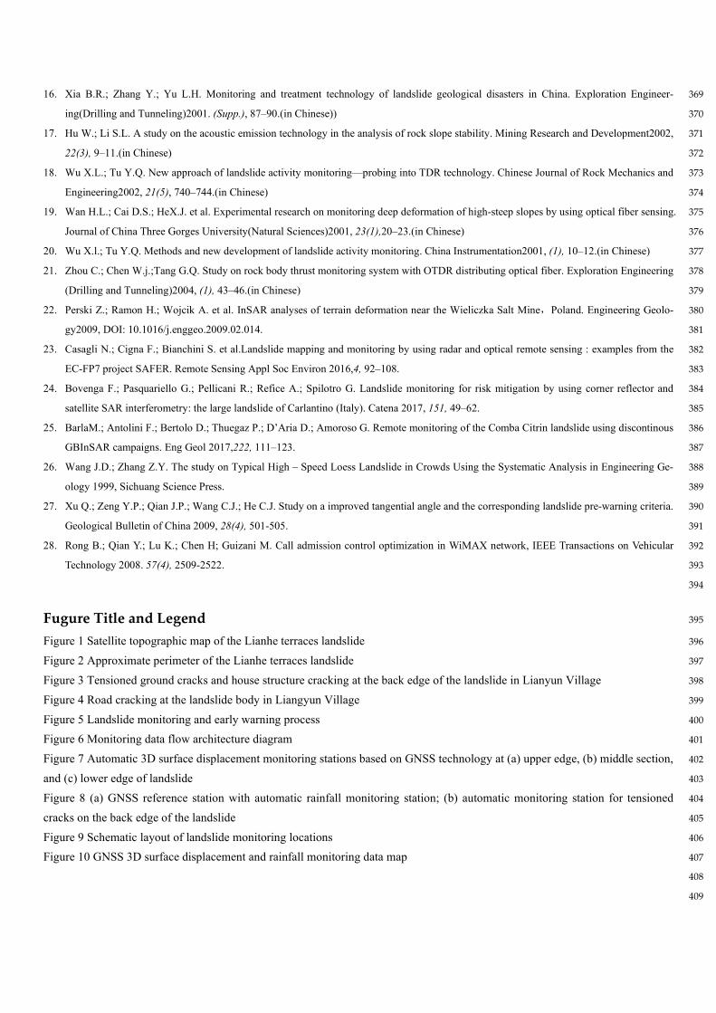
Figure 2. Approximate perimeter of the Lianhe terraces landslide. 106
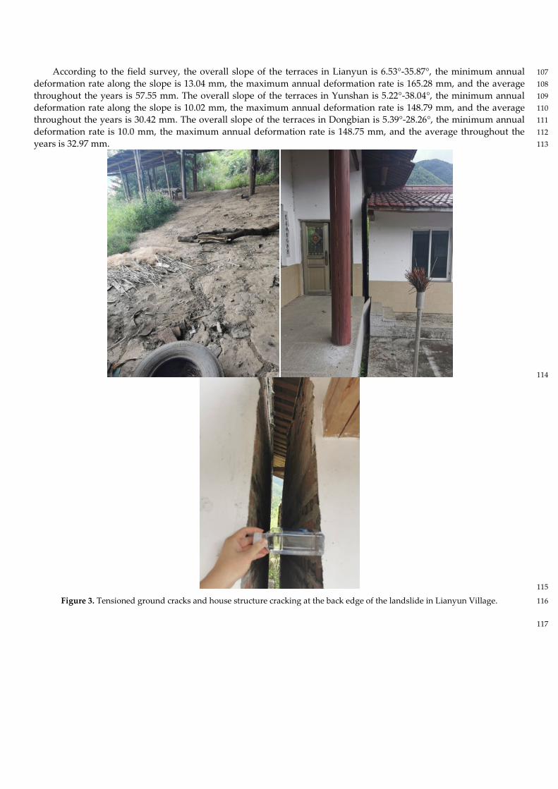
According to the field survey, the overall slope of the terraces in Lianyun is 6.53°-35.87°, the minimum annual 107
deformation rate along the slope is 13.04 mm, the maximum annual deformation rate is 165.28 mm, and the average 108
throughout the years is 57.55 mm. The overall slope of the terraces in Yunshan is 5.22°-38.04°, the minimum annual 109
deformation rate along the slope is 10.02 mm, the maximum annual deformation rate is 148.79 mm, and the average 110
throughout the years is 30.42 mm. The overall slope of the terraces in Dongbian is 5.39°-28.26°, the minimum annual 111
deformation rate is 10.0 mm, the maximum annual deformation rate is 148.75 mm, and the average throughout the 112
years is 32.97 mm. 113
114
115
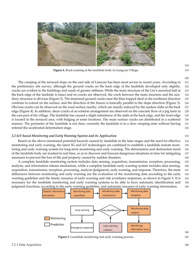
Figure 3. Tensioned ground cracks and house structure cracking at the back edge of the landslide in Lianyun Village. 116
117
118
Figure 4. Road cracking at the landslide body in Liangyun Village. 119
120
The creeping of the terraced slope on the east side of Lianyun has been most severe in recent years. According to 121
the preliminary site survey, although the ground cracks on the back edge of the landslide developed only slightly, 122
cracks are evident in the buildings and roads of greater stiffness. While the main structure of the Lin’s ancestral hall at 123
the back edge of the landside is intact and no cracks are observed, the crack between the main structure and the aux- 124
iliary structure is obvious (Figure 3). The tensioned ground cracks near the blue-topped shed in the northeast direction 125
continue to extend on the surface, and the direction of the fissure is basically parallel to the slope direction (Figure 3). 126
Obvious cracks can be observed on the road surface nearby, which are mainly induced by the sunken slabs at the back 127
edge (Figure 4). In addition, shear cracks of an echelon arrangement are observed on the concrete floor of a pig farm in 128
the east part of the village. The landslide has caused a slight subsidence of the slabs at the back edge, and the front edge 129
is located in the terraced area, with bulging at some locations. The main surface cracks are distributed in a scattered 130
manner. The perimeter of the landslide is not clear, currently the landslide is in a slow creeping state without having 131
entered the accelerated deformation stage. 132
2.2 IoT-based Monitoring and Early Warning System and its Application 133
Based on the above-mentioned potential hazards caused by landslide in the later stages and the need for effective 134
monitoring and early warning, the latest 5G and IoT technologies are combined to establish a landslide remote moni- 135
toring and early warning system for long-term monitoring and early warning. The deformation and destruction trend 136
of the landslide body are tracked in real time, so as to discover and forecast dangerous situations in time for mitigating 137
measures to prevent the loss of life and property caused by sudden disasters. 138
A complete landslide monitoring system includes data sensing, acquisition, transmission, reception, processing, 139
analysis, and information release mechanism, while a complete landslide early warning system includes data sensing, 140
acquisition, transmission, reception, processing, analysis (judgment), early warning, and response. Therefore, the main 141
differences between monitoring and early warning are the evaluation of the monitoring data according to the early 142
warning guideline and the timely issuance of early warning and risk avoidance responses, as shown in Figure 5. It is 143
necessary for the landslide monitoring and early warning systems to be able to have automatic identification and 144
judgment functions, according to the early warning guideline, and automatic issuance of early warning information. 145
146
Figure 5. Landslide monitoring and early warning process. 147
2.2.1 Data Acquisition 148

The data of the system comes from the regular data acquisition with the equipment. At present, the system sup- 149
ports automatic monitoring equipment for GNSS-based 3D surface displacement, rainfall, cracks, groundwater level, 150
second-order power, etc. The equipment communicates directly with the equipment-side server, and the collected data 151
is regularly transmitted to the equipment-side server through the network. 152
To facilitate data exchange with the application-side server, the equipment-side server uses a cache database and 153
periodically transmits data to the application-side server according to the data request specification of the applica- 154
tion-side server. After the application-side server receives the data transmitted from the equipment-side server, the 155
data is pre-processed before entering into the storage center database (see Figure 6 for the data flow architecture). 156
157
Figure 6. Monitoring data flow architecture diagram. 158
159
The user side can request to query the data of the application-side server through the HTTP protocol. Both query 160
by time range and query by specified equipment type are supported. The application-side server will automatically 161
aggregate the data according to the time range of the query. For equipment-specific data that calculates relative values 162
(such as data of GNSS equipment and crack detection equipment), the system automatically calculates the relative data 163
values based on the reference time of the location of the monitoring equipment. 164
165
2.2.2 Data transmission 166
As the latest breakthrough in communication field, 5G communication has present many advantages such as 167
high speed, large capacity and low latency. In the IoT, high-quality and real-time monitored data transmission is often 168
necessary. In particular, many IoT terminal devices will play an important role in the 5G communication system, such 169
as autonomous driving or a surveillance system with a high-definition camera. In 5G networks, a multi-layer structure 170
will be considered, owing to the heterogeneity of equipment and services. Regarding to the IoT, it is a potential tech- 171
nology to realize the interconnection of all things. The popularity of small and inexpensive computing devices with 172
sensing and communication functions is paving the way for the widespread application of IoT [28]. In the monitoring 173
and prediction project of Youxi landslide, the corresponding IoT terminals are used to monitor rainfall, ground fissure 174
and surface deformations in real time, and then 5G communication channels are chosen to transmit data 175
An automatic data acquisition equipment was developed based on the data output interface and communication 176
protocol of a high-precision mechanics sensor. The equipment includes a data acquisition module, a data storage 177
module, a data transmission module, and a solar power supply equipment. The data acquisition equipment is con- 178
nected to the sensors and the solar power supply system through shielded cables to form a complete data acquisition 179
system. 180
In order to improve the stability and reliability of data transmission, each monitoring location in the monitoring 181
area is connected with wireless sensor network technology, and the data are transmitted centrally from the field to the 182
indoor monitoring center using the dual communication mode of BeiDou satellite and GPRS (referred to as BD/GPRS 183
mode) after data acquisition. 184
There are two modes of aggregating data from monitoring locations within the monitoring area, with the mesh 185
networking mode and the linear networking mode. 186
(1) Mesh networking mode: monitoring locations (nodes) can be networked for data transmission at will within 187
the effective range. When one of the monitoring locations fails, other adjacent monitoring locations can be selected for 188
data transmission until the data is finally transmitted to the sink node. The advantage of this transmission mode is 189
that the data transmission is secure, and the data transmission within the whole monitoring area will not be paralyzed 190
due to the failure at one monitoring location (see Figure 6). 191
(2) Linear networking mode: monitoring location Ni and its effective proximity location Ni-1 form a network, Ni-1 192
and Ni-2 form a network, and so on until communication between themonitoring location N1 and the convergence 193
point is obtained, such that data of the N locations on the same line are all converged to the convergence point. The 194
advantage of this transmission mode is the long effective transmission distance, suitable for strip-shaped monitoring 195
area. The disadvantage is that the data transmission stability is not guaranteed, when one of the nodes is damaged, 196
the data transmission of the whole system is paralyzed. 197
Therefore, this system uses two transmission modes in a complementary form, which improves both the effective 198
distance of data transmission as well as the security and stability of data transmission. 199
200
3 Results and discussion 201
3.1 Monitoring network at the Lianhe terraces landslide site in Youxi County 202
203
204
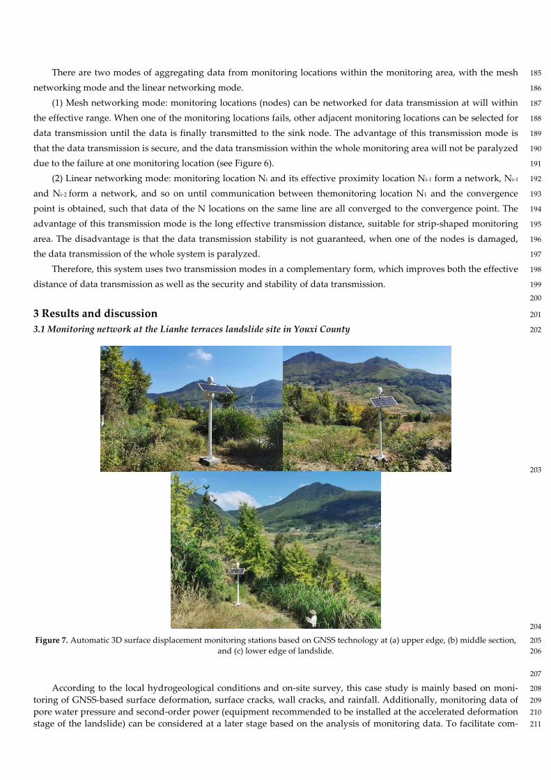
Figure 7. Automatic 3D surface displacement monitoring stations based on GNSS technology at (a) upper edge, (b) middle section, 205 and (c) lower edge of landslide. 206
207
According to the local hydrogeological conditions and on-site survey, this case study is mainly based on moni- 208
toring of GNSS-based surface deformation, surface cracks, wall cracks, and rainfall. Additionally, monitoring data of 209
pore water pressure and second-order power (equipment recommended to be installed at the accelerated deformation 210
stage of the landslide) can be considered at a later stage based on the analysis of monitoring data. To facilitate com- 211
prehensive monitoring of the overall displacement due to the landslide, a GNSS monitoring station was installed along 212
each of the front, middle, and back edges of the landslide in a straight line (see Figure 7), and a reference station was set 213
at a stabilized rock body within 2 km of the landslide body. Since most landslides in this area are induced by rainfall 214
during the rainy season, a rainfall monitoring station was set at the location of the GNSS reference station, as shown in 215
Figure 8a. 216
Taking GPS positioning using in this study for example,relative positioning is most commonly used in static po- 217
sitioning of GPS measurement. Inrelative positioning, the vector of baseline will be calculated, that is, the position of 218
one point in GPS control network relative to another can be obtained. This method is often used in GPS measurement 219
with short baseline. In GPS relative positioning, the second difference of carrier phase observation is generally used as 220
virtual observation. The adjustment calculation is carried out according to the principle of least square adjustment, 221
therefore, this observation model can eliminate clock error. In addition, it can be known that the orbit error after double 222
difference, ionosphere and the influence on the delay of current layer are very small and can even be ignored, thus, the 223
observation model can be simplified. The positioning accuracy of this method is relatively high, which can be applied 224
to engineering measurement. 225
In GPS relative positioning, the second difference observation of carrier phase observation is often used as the 226
virtual observation value in baseline measurement. According to the least square principle, for epoch t, the observation 227
equation of second difference from station i and j for satellite p and q is 228
p
i
p
j
q
i
q
j
p
ij
q
ij
pq
ij Φ−Φ−Φ−Φ=Φ∇−Φ∇=Φ∇∆ (1) 229
Suppose that at epoch t, stations i and j synchronously observe four satellites whose numbers are 1, 2, 3 and 4 in 230
the sky, and set satellite 1 as the reference star. The matrix of the observation equation of quadratic difference can be 231
expressed as: 232
Φ=Φ∇∆ B (2) 233
where 234
Φ∇∆
Φ∇∆
Φ∇∆
=Φ∇∆14
13
12
ij
ij
ij
,
−−−−
−−=
11000011
00110011
00001111
B
, 235
][ T
jijijiji
44332211 ΦΦΦΦΦΦΦΦ=Φ 236
In GPS baseline measurement, it is usually assumed that one end of the baseline is a known point. In epoch t, the 237
error equation of quadratic difference obtained by synchronous observation of satellites p and q by stations i and j is 238
ijp
j
p
j
q
j
q
jpq
ij XXXXX
c
fV δ
ρρ)
)()((
0
0
0
0 −−
−= ijp
j
p
j
q
j
q
jY
YYYY
c
f δρρ
))()(
(0
0
0
0 −−
−+
239
ijp
j
p
j
q
j
q
jZ
ZZZZ
c
f δρρ
))()(
(0
0
0
0 −−
−+
pq
ij
pq
ij lN −− (3) 240
where the remaining terms in the error are expressed as pq
ijl . In Equation (3), it is assumed that the ionosphere, 241
troposphere and other errors can be eliminated. 242
Furthermore, the observation equation of the quadratic difference at epoch t can be obtained 243
LAXV += (4) 244
where 245
][ T
ijijij VVVV 141312=,
][ T
ijijij lllL 141312=, 246
][ T
ijijijijijij NNNZYXX 141312δδδ=, 247
−−
−−−
−−−
−
−−
−−−
−−−
−
−−
−−−
−−−
−
=
100)(1
)(1
)(1
010)(1
)(1
)(1
001)(1
)(1
)(1
)(
1
1
4
4
1
1
4
4
1
1
4
4
1
1
3
3
1
1
3
3
1
1
3
3
1
1
2
2
1
1
2
2
1
1
2
2
j
j
j
j
j
j
j
j
j
j
j
j
j
j
j
j
j
j
j
j
j
j
j
j
j
j
j
j
j
j
j
j
j
j
j
j
ZZZZYYYYXXXX
ZZZZYYYYXXXX
ZZZZYYYYXXXX
tA
ρρλρρλρρλ
ρρλρρλρρλ
ρρλρρλρρλ
248 For mth observation epoch, the coefficient matrix of observation equation of quadratic difference can be expressed 249
as 250
[ ] T
mtAtAtAA )()()( 21 ⋅⋅⋅= (5) 251
Using the least square method 252
min=PVV T
(6) 253
By substituting Equation (4) into Equation (6), the correction term V is obtained, and the average value of the ob- 254
served value is obtained 255
VXX += δδ ˆ 256
VXY += δδ ˆ (7) 257
VXZ += δδ ˆ 258
Using this method, when the location( 000 ,, ZYX ) of the reference station is known, the coordinate of mobile 259
station can be obtained. 260
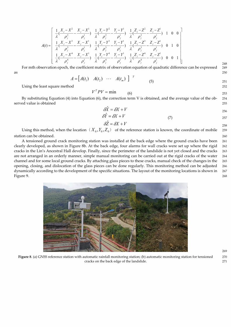
A tensioned ground crack monitoring station was installed at the back edge where the ground cracks have been 261
clearly developed, as shown in Figure 8b. At the back edge, four alarms for wall cracks were set up where the rigid 262
cracks in the Lin’s Ancestral Hall develop. Finally, since the perimeter of the landslide is not yet closed and the cracks 263
are not arranged in an orderly manner, simple manual monitoring can be carried out at the rigid cracks of the water 264
channel and for some local ground cracks. By attaching glass pieces to these cracks, manual check of the changes in the 265
opening, closing, and dislocation of the glass pieces can be done regularly. This monitoring method can be adjusted 266
dynamically according to the development of the specific situations. The layout of the monitoring locations is shown in 267
Figure 9. 268
269
Figure 8. (a) GNSS reference station with automatic rainfall monitoring station; (b) automatic monitoring station for tensioned 270 cracks on the back edge of the landslide. 271
272
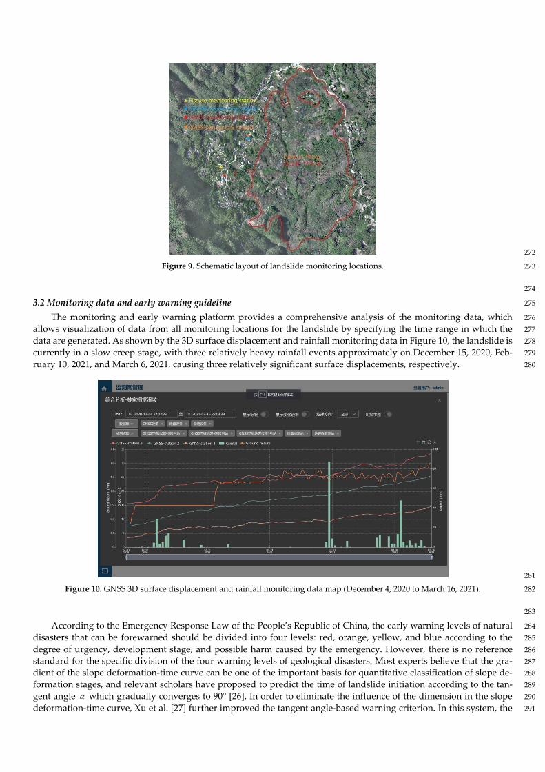
Figure 9. Schematic layout of landslide monitoring locations. 273
274
3.2 Monitoring data and early warning guideline 275
The monitoring and early warning platform provides a comprehensive analysis of the monitoring data, which 276
allows visualization of data from all monitoring locations for the landslide by specifying the time range in which the 277
data are generated. As shown by the 3D surface displacement and rainfall monitoring data in Figure 10, the landslide is 278
currently in a slow creep stage, with three relatively heavy rainfall events approximately on December 15, 2020, Feb- 279
ruary 10, 2021, and March 6, 2021, causing three relatively significant surface displacements, respectively. 280
281
Figure 10. GNSS 3D surface displacement and rainfall monitoring data map (December 4, 2020 to March 16, 2021). 282
283
According to the Emergency Response Law of the People’s Republic of China, the early warning levels of natural 284
disasters that can be forewarned should be divided into four levels: red, orange, yellow, and blue according to the 285
degree of urgency, development stage, and possible harm caused by the emergency. However, there is no reference 286
standard for the specific division of the four warning levels of geological disasters. Most experts believe that the gra- 287
dient of the slope deformation-time curve can be one of the important basis for quantitative classification of slope de- 288
formation stages, and relevant scholars have proposed to predict the time of landslide initiation according to the tan- 289
gent angle 𝛼𝛼 which gradually converges to 90° [26]. In order to eliminate the influence of the dimension in the slope 290
deformation-time curve, Xu et al. [27] further improved the tangent angle-based warning criterion. In this system, the 291
improved tangent angle-based warning criterion is introduced to analyze and warn about slope stability and land- 292
slides based on real-time monitoring data, and the early warning criteria are shown in Table 1. 293
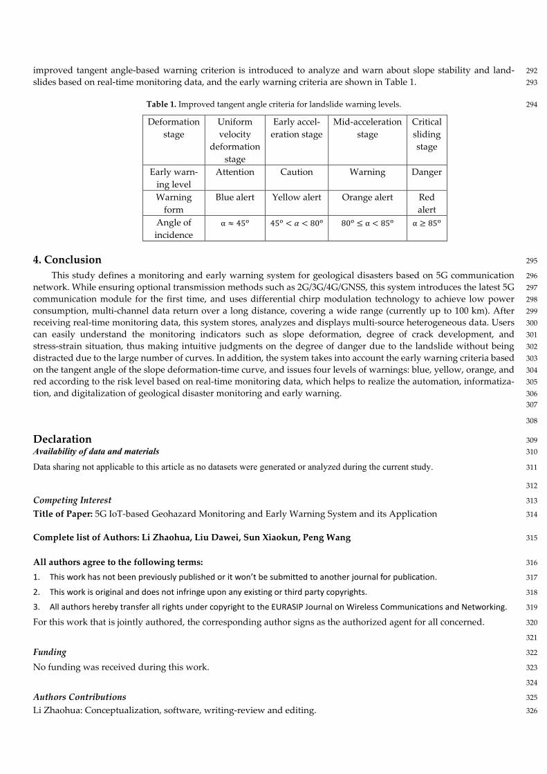
Table 1. Improved tangent angle criteria for landslide warning levels. 294
Deformation
stage
Uniform
velocity
deformation
stage
Early accel-
eration stage
Mid-acceleration
stage
Critical
sliding
stage
Early warn-
ing level
Attention Caution Warning Danger
Warning
form
Blue alert Yellow alert Orange alert Red
alert
Angle of
incidence
α ≈ 45o 45
o< 𝛼𝛼 < 80
o 80o ≤ α < 85
o α ≥ 85o
4. Conclusion 295
This study defines a monitoring and early warning system for geological disasters based on 5G communication 296
network. While ensuring optional transmission methods such as 2G/3G/4G/GNSS, this system introduces the latest 5G 297
communication module for the first time, and uses differential chirp modulation technology to achieve low power 298
consumption, multi-channel data return over a long distance, covering a wide range (currently up to 100 km). After 299
receiving real-time monitoring data, this system stores, analyzes and displays multi-source heterogeneous data. Users 300
can easily understand the monitoring indicators such as slope deformation, degree of crack development, and 301
stress-strain situation, thus making intuitive judgments on the degree of danger due to the landslide without being 302
distracted due to the large number of curves. In addition, the system takes into account the early warning criteria based 303
on the tangent angle of the slope deformation-time curve, and issues four levels of warnings: blue, yellow, orange, and 304
red according to the risk level based on real-time monitoring data, which helps to realize the automation, informatiza- 305
tion, and digitalization of geological disaster monitoring and early warning. 306 307
308
Declaration 309 Availability of data and materials 310
Data sharing not applicable to this article as no datasets were generated or analyzed during the current study. 311
312
Competing Interest 313
Title of Paper: 5G IoT-based Geohazard Monitoring and Early Warning System and its Application 314
Complete list of Authors: Li Zhaohua, Liu Dawei, Sun Xiaokun, Peng Wang 315
All authors agree to the following terms: 316
1. This work has not been previously published or it won’t be submitted to another journal for publication. 317
2. This work is original and does not infringe upon any existing or third party copyrights. 318
3. All authors hereby transfer all rights under copyright to the EURASIP Journal on Wireless Communications and Networking. 319
For this work that is jointly authored, the corresponding author signs as the authorized agent for all concerned. 320
321
Funding 322
No funding was received during this work. 323
324
Authors Contributions 325
Li Zhaohua: Conceptualization, software, writing-review and editing. 326
Liu Dawei: Funding acquisition, project administration, methodology. 327
Sun Xiaokun: Writing-original draft preparation. 328
Peng Wang: validation. 329
330
List of Abbreviations 331
IoT: Internet of Things 332
GNSS: Global Navigation Satellite System 333
InSAR: Interferometric Synthetic Aperture Radar 334
GPS: Global Positioning System 335
336
337
338
339
References 340
1. Lavigne F.; Wassmer P.; Gomez C.; Davies T.A.; Hadoko D.S.; Yan T. The 21 February 2005, catastrophic waste avalanche at Leuwigajah 341
dumpsite, Bandung, Indonesia. Geoenviron Disasters 2014,1(1), 10. 342
2. Anua´rio. Brasileiro de Desastres Naturais, Ministery of National Integration, National Center for Management of Risks and Disasters, 343
2012, Brası´lia, 78 344
3. Guadagno F.M; Revellino P,; Grelle G. The 1998 Sarnolandslides: conflicting interpretations of a natural event. In:International confrence 345
on debris-flow hazards mitigation: mechanics 2001. 346
4. Jafari N.H.; Stark T.D.; Merry S. The July 10, 2000 Payatas landfill slope failure. Int J Geoeng Case Hist 2013, 2(3), 208–228. 347
5. Merry S.; Kavazanjian E. Jr.; Fritz WU. Reconnaissance of the July 10, 2000, Payatas landfill failure. J Perform Constr Facil 2005, 19(2), 348
100–107 349
6. Li Y.Y.Mechanisms and kinetic behaviours of landslide and debris flow. Landslide Symposium, 1987, Sichuang Science Press. (in Chinese) 350
7. Wu C.X.; Xu L.; Dai F.C.Topographic features and initiation of earth flows on Heifangtai loess plateau. Rock and Soil Mechanics, 2011, 351
32(6), 1767-1773. (in Chinese). 352
8. Zhang D.X.; Wang G.H.; Luo C.Y.; Chen J.; Zhou Y.X. A rapid loess flowslide triggered by irrigation in China. Landslides 2009,6(1), 353
55-60. 354
9. Yao X.; Yu K.; Zhang Y.S.; Li L.J.; Zhou N.J. Mechanisms of catastrophic landslide on January 11, 2013, in Zhenxiong county: fluidization 355
initiation and movement liquefaction of high porosity soil. Chinese Journal of Rock Mechanics and Engineering 2014. 33(5),1047-1054. 356
10. Yuan R.M.; Tang C.L.; Hu J.C.; Xu X.W. Mechanism of the Donghekou landslide triggered by the 2008 Wenchuan earthquake revealed by 357
discrete element modeling. Natural Hazards and Earth System Sciences 2014, 14(5), 1195-1205(11). 358
11. Yin Y.P.; Liu C.Z.; Chen H.Q. Investigation on catastrophic landslide of January 11, 2013 at Zhaojiagou, Zhenxiong county, Yunnan prov- 359
ince. Journal of Engineering Geology 2013, 21(1),6-15. 360
12. Yin Y.P.; Xing A.G.; Wang G.H.; Feng Z.; Li B.; Jiang Y. Experimental and numerical investigations of a catastrophic long-runout landslide 361
in Zhenxiong, Yunnan, southwestern China. Landslides 2017, 14(2), 649-659. 362
13. Xu Q.; Peng D.L.; Li W.L.; Dong X.J; Hu W.; Tang M.G.; Liu F.Z. The catastrophic landfill flowslide at Hongao dumpsite on 20 Decem- 363
ber 2015 in Shenzhen, China. Natural Hazards and Earth System Sciences 2017. Published online. 364
14. Ouyang C.J.; Zhou K.Q.; Xu Q.; Yin J.H.; Peng D.L.; Wang D.P.; Li W. Dynamic analysis and numerical modeling of the 2015 cata- 365
strophic landslide of the construction waste landfill at Guangming, Shenzhen, China. Landslides 2016,14(2), 705-718. 366
15. Li Z.H.; Jiang Y.J.; Lv Q.; Sousa L.; He M.C. Consistent modeling of a catastrophic flowslide at the Shenzhen landfill using a hy- 367
dro-elasto-plastic model with solid-fluid transition. Acta Geotechnica 2018,13(6), 1451-1466. 368
16. Xia B.R.; Zhang Y.; Yu L.H. Monitoring and treatment technology of landslide geological disasters in China. Exploration Engineer- 369
ing(Drilling and Tunneling)2001. (Supp.), 87–90.(in Chinese)) 370
17. Hu W.; Li S.L. A study on the acoustic emission technology in the analysis of rock slope stability. Mining Research and Development2002, 371
22(3), 9–11.(in Chinese) 372
18. Wu X.L.; Tu Y.Q. New approach of landslide activity monitoring—probing into TDR technology. Chinese Journal of Rock Mechanics and 373
Engineering2002, 21(5), 740–744.(in Chinese) 374
19. Wan H.L.; Cai D.S.; HeX.J. et al. Experimental research on monitoring deep deformation of high-steep slopes by using optical fiber sensing. 375
Journal of China Three Gorges University(Natural Sciences)2001, 23(1),20–23.(in Chinese) 376
20. Wu X.l.; Tu Y.Q. Methods and new development of landslide activity monitoring. China Instrumentation2001, (1), 10–12.(in Chinese) 377
21. Zhou C.; Chen W.j.;Tang G.Q. Study on rock body thrust monitoring system with OTDR distributing optical fiber. Exploration Engineering 378
(Drilling and Tunneling)2004, (1), 43–46.(in Chinese) 379
22. Perski Z.; Ramon H.; Wojcik A. et al. InSAR analyses of terrain deformation near the Wieliczka Salt Mine,Poland. Engineering Geolo- 380
gy2009, DOI: 10.1016/j.enggeo.2009.02.014. 381
23. Casagli N.; Cigna F.; Bianchini S. et al.Landslide mapping and monitoring by using radar and optical remote sensing : examples from the 382
EC-FP7 project SAFER. Remote Sensing Appl Soc Environ 2016,4, 92–108. 383
24. Bovenga F.; Pasquariello G.; Pellicani R.; Refice A.; Spilotro G. Landslide monitoring for risk mitigation by using corner reflector and 384
satellite SAR interferometry: the large landslide of Carlantino (Italy). Catena 2017, 151, 49–62. 385
25. BarlaM.; Antolini F.; Bertolo D.; Thuegaz P.; D’Aria D.; Amoroso G. Remote monitoring of the Comba Citrin landslide using discontinous 386
GBInSAR campaigns. Eng Geol 2017,222, 111–123. 387
26. Wang J.D.; Zhang Z.Y. The study on Typical High – Speed Loess Landslide in Crowds Using the Systematic Analysis in Engineering Ge- 388
ology 1999, Sichuang Science Press. 389
27. Xu Q.; Zeng Y.P.; Qian J.P.; Wang C.J.; He C.J. Study on a improved tangential angle and the corresponding landslide pre-warning criteria. 390
Geological Bulletin of China 2009, 28(4), 501-505. 391
28. Rong B.; Qian Y.; Lu K.; Chen H; Guizani M. Call admission control optimization in WiMAX network, IEEE Transactions on Vehicular 392
Technology 2008. 57(4), 2509-2522. 393
394
Fugure Title and Legend 395
Figure 1 Satellite topographic map of the Lianhe terraces landslide 396
Figure 2 Approximate perimeter of the Lianhe terraces landslide 397
Figure 3 Tensioned ground cracks and house structure cracking at the back edge of the landslide in Lianyun Village 398
Figure 4 Road cracking at the landslide body in Liangyun Village 399
Figure 5 Landslide monitoring and early warning process 400
Figure 6 Monitoring data flow architecture diagram 401
Figure 7 Automatic 3D surface displacement monitoring stations based on GNSS technology at (a) upper edge, (b) middle section, 402
and (c) lower edge of landslide 403
Figure 8 (a) GNSS reference station with automatic rainfall monitoring station; (b) automatic monitoring station for tensioned 404
cracks on the back edge of the landslide 405
Figure 9 Schematic layout of landslide monitoring locations 406
Figure 10 GNSS 3D surface displacement and rainfall monitoring data map 407
408
409
Figures
Figure 1
Satellite topographic map of the Lianhe terraces landslide.
Figure 2
Approximate perimeter of the Lianhe terraces landslide.
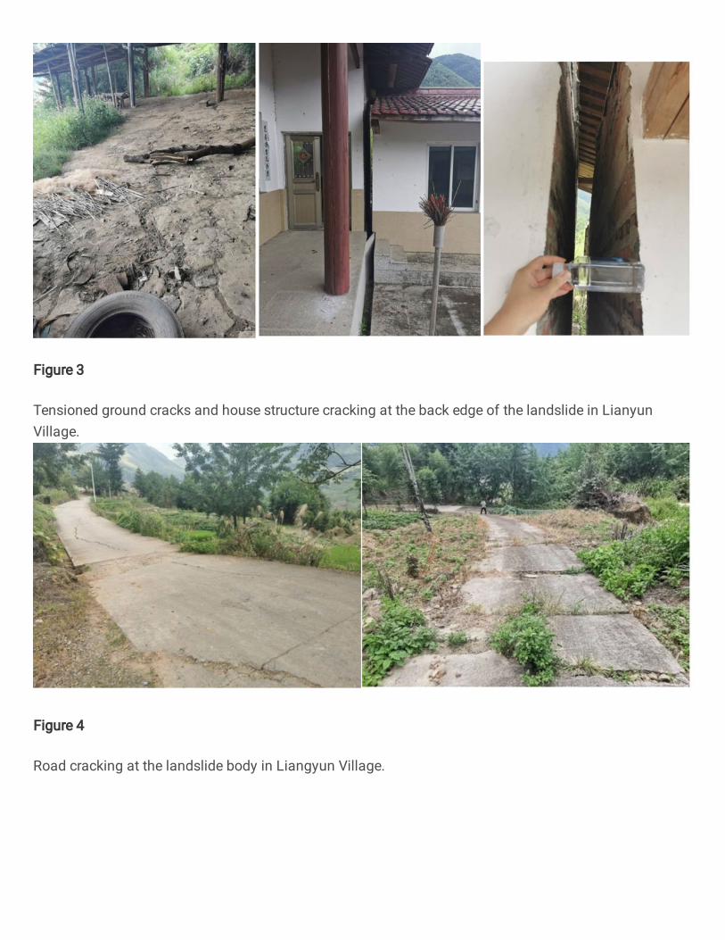
Figure 3
Tensioned ground cracks and house structure cracking at the back edge of the landslide in LianyunVillage.
Figure 4
Road cracking at the landslide body in Liangyun Village.
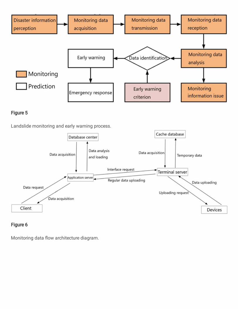
Figure 5
Landslide monitoring and early warning process.
Figure 6
Monitoring data �ow architecture diagram.
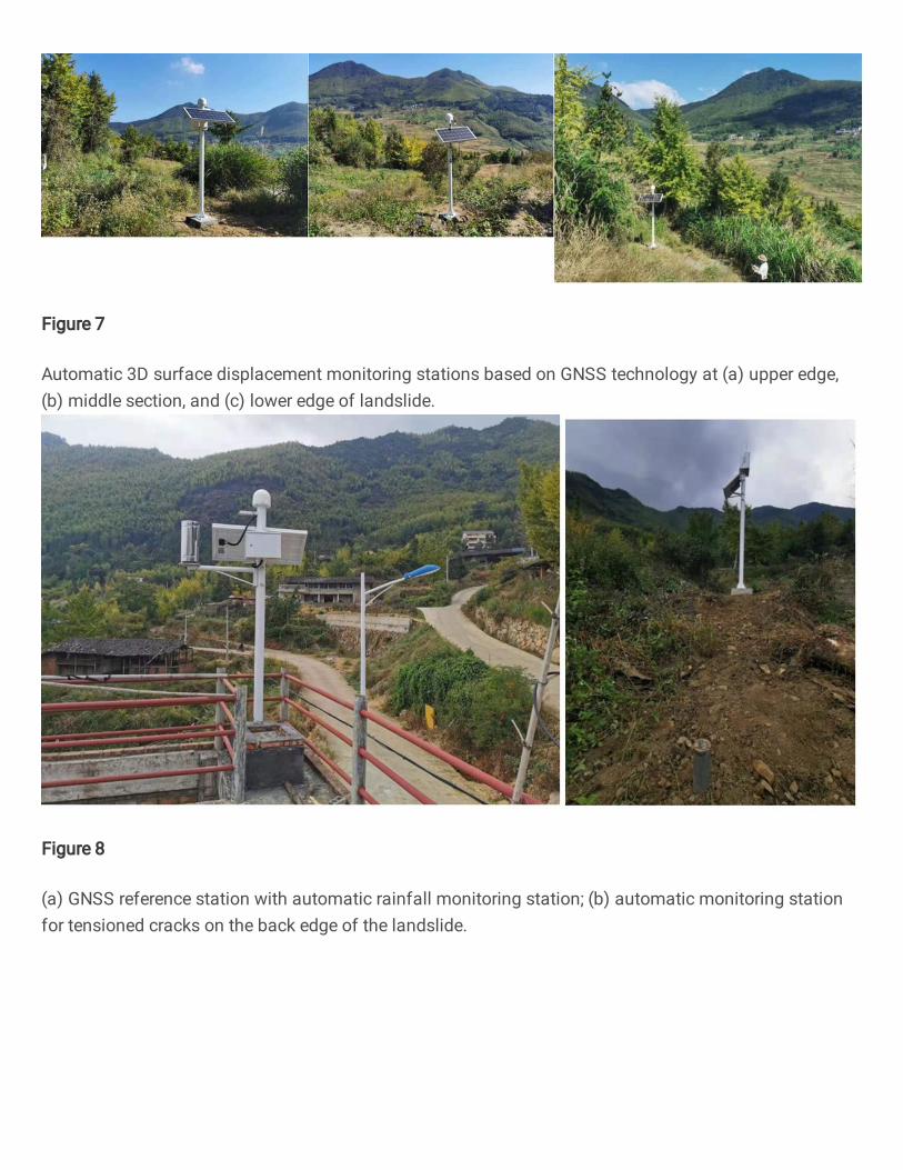
Figure 7
Automatic 3D surface displacement monitoring stations based on GNSS technology at (a) upper edge,(b) middle section, and (c) lower edge of landslide.
Figure 8
(a) GNSS reference station with automatic rainfall monitoring station; (b) automatic monitoring stationfor tensioned cracks on the back edge of the landslide.
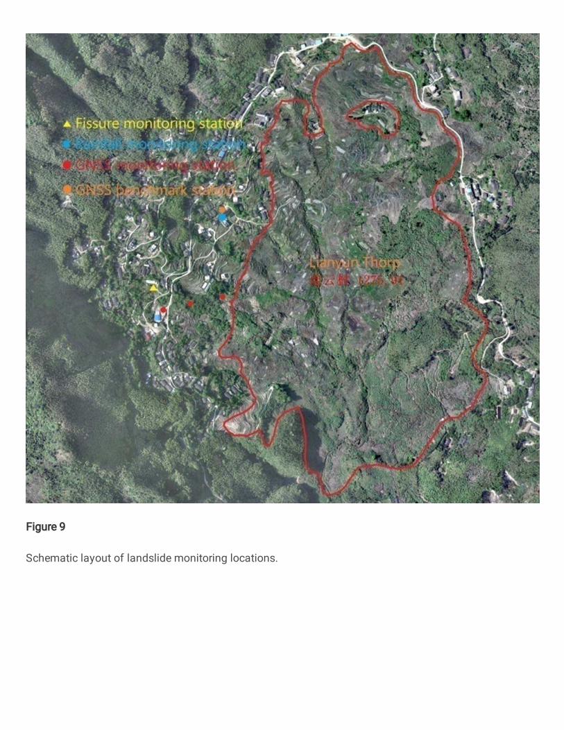
Figure 9
Schematic layout of landslide monitoring locations.
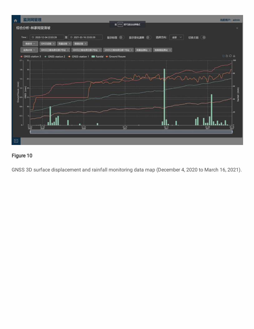
Figure 10
GNSS 3D surface displacement and rainfall monitoring data map (December 4, 2020 to March 16, 2021).