Embed Size (px)
Citation preview
PLEA 2008 – 25th Conference on Passive and Low Energy Architecture, Dublin, 22nd to 24th October 2008
597: ARCHITECTURAL DESIGN AND ENERGY ANALYSIS OF A COMPLEX OF RESIDENTIAL BUILDINGS IN PARIS
F. Leccese, G. Salvadori, G. Tuoni, P.L. D’Acunto
Department of Energy “L. Poggi”, Faculty of Engineering, University of Pisa, Pisa (Italy) [email protected], [email protected], [email protected]
Abstract In this paper the energy performance of a residential building in Paris, designed within the International Architectural Competition HABITER PARIS (as concerns the suburban quarter of Porte des Lilas) are analyzed. According to EN 12831 and EN 832 the building winter energy demand has been evaluated to prove the low-energy-consumption behaviour of the building. Keywords: energy conscious design, building energy labelling, low energy consumption building, multi-layered light walls.
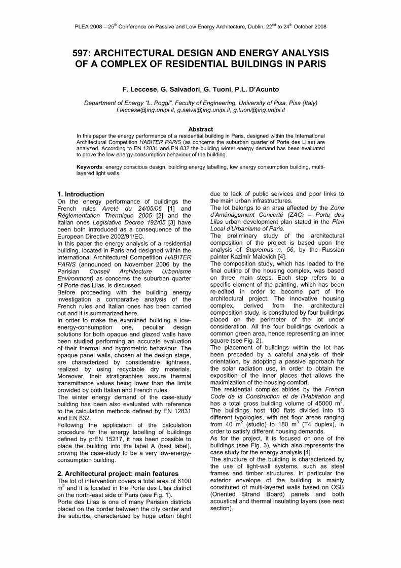
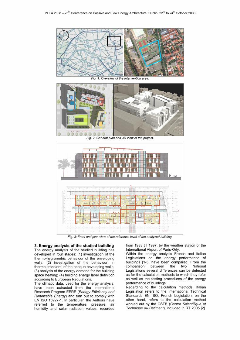
1. Introduction On the energy performance of buildings the French rules Arreté du 24/05/06 [1] and Réglementation Thermique 2005 [2] and the Italian ones Legislative Decree 192/05 [3] have been both introduced as a consequence of the European Directive 2002/91/EC. In this paper the energy analysis of a residential building, located in Paris and designed within the International Architectural Competition HABITER PARIS (announced on November 2006 by the Parisian Conseil Architecture Urbanisme Environment) as concerns the suburban quarter of Porte des Lilas, is discussed. Before proceeding with the building energy investigation a comparative analysis of the French rules and Italian ones has been carried out and it is summarized here. In order to make the examined building a low-energy-consumption one, peculiar design solutions for both opaque and glazed walls have been studied performing an accurate evaluation of their thermal and hygrometric behaviour. The opaque panel walls, chosen at the design stage, are characterized by considerable lightness, realized by using recyclable dry materials. Moreover, their stratigraphies assure thermal transmittance values being lower than the limits provided by both Italian and French rules. The winter energy demand of the case-study building has been also evaluated with reference to the calculation methods defined by EN 12831 and EN 832. Following the application of the calculation procedure for the energy labelling of buildings defined by prEN 15217, it has been possible to place the building into the label A (best label), proving the case-study to be a very low-energy-consumption building. 2. Architectural project: main features The lot of intervention covers a total area of 6100 m2 and it is located in the Porte des Lilas district on the north-east side of Paris (see Fig. 1). Porte des Lilas is one of many Parisian districts placed on the border between the city center and the suburbs, characterized by huge urban blight
due to lack of public services and poor links to the main urban infrastructures. The lot belongs to an area affected by the Zone d’Aménagement Concerté (ZAC) – Porte des Lilas urban development plan stated in the Plan Local d’Urbanisme of Paris. The preliminary study of the architectural composition of the project is based upon the analysis of Supremus n. 56, by the Russian painter Kazimir Malevich [4]. The composition study, which has leaded to the final outline of the housing complex, was based on three main steps. Each step refers to a specific element of the painting, which has been re-edited in order to become part of the architectural project. The innovative housing complex, derived from the architectural composition study, is constituted by four buildings placed on the perimeter of the lot under consideration. All the four buildings overlook a common green area, hence representing an inner square (see Fig. 2). The placement of buildings within the lot has been preceded by a careful analysis of their orientation, by adopting a passive approach for the solar radiation use, in order to obtain the exposition of the inner places that allows the maximization of the housing comfort. The residential complex abides by the French Code de la Construction et de l’Habitation and has a total gross building volume of 45000 m3. The buildings host 100 flats divided into 13 different typologies, with net floor areas ranging from 40 m2 (studio) to 180 m3 (T4 duplex), in order to satisfy different housing demands. As for the project, it is focused on one of the buildings (see Fig. 3), which also represents the case study for the energy analysis [4]. The structure of the building is characterized by the use of light-wall systems, such as steel frames and timber structures. In particular the exterior envelope of the building is mainly constituted of multi-layered walls based on OSB (Oriented Strand Board) panels and both acoustical and thermal insulating layers (see next section).
PLEA 2008 – 25th Conference on Passive and Low Energy Architecture, Dublin, 22nd to 24th October 2008
Fig. 1: Overview of the intervention area.
Fig. 2: General plan and 3D view of the project.
Fig. 3: Front and plan view of the reference level of the analyzed building.
3. Energy analysis of the studied building The energy analysis of the studied building has developed in four stages: (1) investigation of the thermo-hygrometric behaviour of the enveloping walls; (2) investigation of the behaviour, in thermal transient, of the opaque enveloping walls; (3) analysis of the energy demand for the building space heating; (4) building energy label definition according to European Regulations. The climatic data, used for the energy analysis, have been extracted from the International Research Program EERE (Energy Efficiency and Renewable Energy) and turn out to comply with EN ISO 15927-1. In particular, the Authors have referred to the temperature, pressure, air humidity and solar radiation values, recorded
from 1983 till 1997, by the weather station of the International Airport of Paris-Orly. Within the energy analysis French and Italian Legislations on the energy performance of buildings [1-3] have been compared. From the comparison between the two National Legislations several differences can be detected as for the calculation methods to which they refer as well as the testing procedures of the energy performance of buildings. Regarding to the calculation methods, Italian Legislation refers to the International Technical Standards EN ISO, French Legislation, on the other hand, refers to the calculation method worked out by the CSTB (Centre Scientifique et Technique du Bâtiment), included in RT 2005 [2].
PLEA 2008 – 25th Conference on Passive and Low Energy Architecture, Dublin, 22nd to 24th October 2008
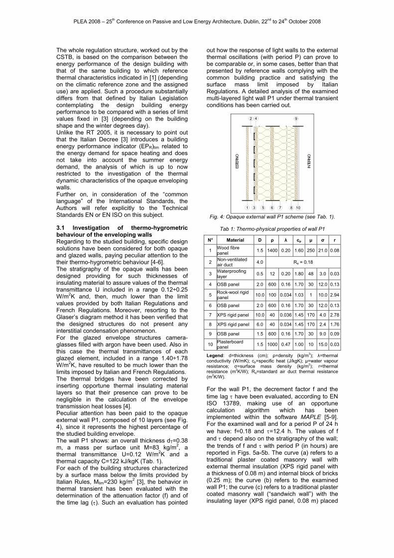
The whole regulation structure, worked out by the CSTB, is based on the comparison between the energy performance of the design building with that of the same building to which reference thermal characteristics indicated in [1] (depending on the climatic reference zone and the assigned use) are applied. Such a procedure substantially differs from that defined by Italian Legislation contemplating the design building energy performance to be compared with a series of limit values fixed in [3] (depending on the building shape and the winter degrees day). Unlike the RT 2005, it is necessary to point out that the Italian Decree [3] introduces a building energy performance indicator (EPR)lim related to the energy demand for space heating and does not take into account the summer energy demand, the analysis of which is up to now restricted to the investigation of the thermal dynamic characteristics of the opaque enveloping walls. Further on, in consideration of the “common language” of the International Standards, the Authors will refer explicitly to the Technical Standards EN or EN ISO on this subject. 3.1 Investigation of thermo-hygrometric behaviour of the enveloping walls Regarding to the studied building, specific design solutions have been considered for both opaque and glazed walls, paying peculiar attention to the their thermo-hygrometric behaviour [4-6]. The stratigraphy of the opaque walls has been designed providing for such thicknesses of insulating material to assure values of the thermal transmittance U included in a range 0.12÷0.25 W/m2K and, then, much lower than the limit values provided by both Italian Regulations and French Regulations. Moreover, resorting to the Glaser’s diagram method it has been verified that the designed structures do not present any interstitial condensation phenomenon. For the glazed envelope structures camera-glasses filled with argon have been used. Also in this case the thermal transmittances of each glazed element, included in a range 1.40÷1.78 W/m2K, have resulted to be much lower than the limits imposed by Italian and French Regulations. The thermal bridges have been corrected by inserting opportune thermal insulating material layers so that their presence can prove to be negligible in the calculation of the envelope transmission heat losses [4]. Peculiar attention has been paid to the opaque external wall P1, composed of 10 layers (see Fig. 4), since it represents the highest percentage of the studied building envelope. The wall P1 shows: an overall thickness dT=0.38 m, a mass per surface unit M=83 kg/m2, a thermal transmittance U=0.12 W/m2K and a thermal capacity C=122 kJ/kgK (Tab. 1). For each of the building structures characterized by a surface mass below the limits provided by Italian Rules, Mlim=230 kg/m2 [3], the behavior in thermal transient has been evaluated with the determination of the attenuation factor (f) and of the time lag (τ). Such an evaluation has pointed
out how the response of light walls to the external thermal oscillations (with period P) can prove to be comparable or, in some cases, better than that presented by reference walls complying with the common building practice and satisfying the surface mass limit imposed by Italian Regulations. A detailed analysis of the examined multi-layered light wall P1 under thermal transient conditions has been carried out.
1
2
3
4
5 6 7 8
9
10
ESTE
RNO
INTE
RNO
Fig. 4: Opaque external wall P1 scheme (see Tab. 1).
Tab 1: Thermo-physical properties of wall P1
N° Material D ρ λ cp μ σ r
1 Wood fibre panel 1.5 1400 0.20 1.60 250 21.0 0.08
2 Non-ventilated air duct 4.0 Ra = 0.18
3 Waterproofing layer 0.5 12 0.20 1.80 48 3.0 0.03
4 OSB panel 2.0 600 0.16 1.70 30 12.0 0.13
5 Rock-wool rigid panel 10.0 100 0.034 1.03 1 10.0 2.94
6 OSB panel 2.0 600 0.16 1.70 30 12.0 0.13
7 XPS rigid panel 10.0 40 0.036 1.45 170 4.0 2.78
8 XPS rigid panel 6.0 40 0.034 1.45 170 2.4 1.76
9 OSB panel 1.5 600 0.16 1.70 30 9.0 0.09
10 Plasterboard panel 1.5 1000 0.47 1.00 10 15.0 0.03
Legend: d=thickness (cm); ρ=density (kg/m3); λ=thermal conductivity (W/mK); cp=specific heat (J/kgK); μ=water vapour resistance; σ=surface mass density (kg/m2); r=thermal resistance (m2K/W); Ra=standard air duct thermal resistance (m2K/W). For the wall P1, the decrement factor f and the time lag τ have been evaluated, according to EN ISO 13789, making use of an opportune calculation algorithm which has been implemented within the software MAPLE [5-9]. For the examined wall and for a period P of 24 h we have: f=0.18 and τ=12.4 h. The values of f and τ depend also on the stratigraphy of the wall; the trends of f and τ with period P (in hours) are reported in Figs. 5a-5b. The curve (a) refers to a traditional plaster coated masonry wall with external thermal insulation (XPS rigid panel with a thickness of 0.08 m) and internal block of bricks (0.25 m); the curve (b) refers to the examined wall P1; the curve (c) refers to a traditional plaster coated masonry wall (“sandwich wall”) with the insulating layer (XPS rigid panel, 0.08 m) placed
PLEA 2008 – 25th Conference on Passive and Low Energy Architecture, Dublin, 22nd to 24th October 2008
between two layers made of brick (each one 0.12 m). Obviously, the two traditional masonry walls show the same overall thickness (dT=0.35 m), the same thermal resistance (U=0.35 m2K/W), the same thermal capacity (C=360 kJ/kgK) and the same mass per surface unit (M=400 kg/m2>Mlim). The graphs of Figs. 5a-5b show the behaviour of the light multi-layered wall P1 in comparison with each of the two traditional walls: the wall P1 has a thermal transient behaviour better than the other walls (for P<50 h, see Fig. 5b) with regard to time lag and better than the “sandwich wall” with regard to decrement factor for all P (see Fig. 5a).
Fig. 5a: Trend of the decrement factor f with P.
Fig. 5b:Trend of the time lag τ with P.
3.2 Analysis of the building winter energy consumption The energy analysis of the examined building has been carried out according to the calculation methods provided by EN 12831 (integrated with [9]), for the evaluation of the design thermal load, and by EN 832, for the evaluation of the space heating energy demand. For the winter energy demand of the building being studied, the heated volume has been subdivided into four parts, each bordering the outside or the non-heated volume (stairs and corridors). The gross heated volume is V=6380 m3. The surface delimiting the heated volume V outwards, or rather towards rooms not provided with heating plant, is S=4900 m2, while the useful area is Su=2320 m2. The conventional heating period, for the examined location, has been considered to occur from the 15th of October till the 15th of April (182 days).
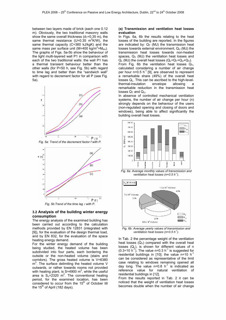
(a) Transmission and ventilation heat losses evaluation In Figs. 6a, 6b the results relating to the heat losses of the building are reported. In the figures are indicated by: QT (MJ) the transmission heat losses towards external environment, QU (MJ) the transmission heat losses towards non-heated spaces, QV (MJ) the ventilation heat losses and QL (MJ) the overall heat losses (QL=QT+QU+QV). From Fig. 6b the ventilation heat losses QV, calculated considering a number of air change per hour n=0.5 h-1 [9], are observed to represent a remarkable share (49%) of the overall heat losses QL. This can be ascribed to the high-level-thermal-insulation envelope allowing a remarkable reduction in the transmission heat losses QT and QU. In absence of controlled mechanical ventilation systems, the number of air change per hour (n) strongly depends on the behaviour of the users (non-regulated opening and closing of doors and windows), being able to affect significantly the building overall heat losses.
Fig. 6a: Average monthly values of transmission and
ventilation heat losses (n=0.5 h-1).
Fig. 6b: Average yearly values of transmission and
ventilation heat losses (n=0.5 h-1). In Tab. 2 the percentage weight of the ventilation heat losses (QV) compared with the overall heat losses (QL), is shown for different values of n (0.3÷10 h-1). The value n=0.3 h-1 is suggested for residential buildings in [10]; the value n=10 h-1 can be considered as representative of the limit case relating to windows remaining opened all day long. The value n=0.8 h-1 is indicated as reference value for natural ventilation of residential buildings in [12]. From the results reported in Tab. 2 it can be noticed that the weight of ventilation heat losses becomes double when the number of air change
PLEA 2008 – 25th Conference on Passive and Low Energy Architecture, Dublin, 22nd to 24th October 2008
per hour (n) is increased from 0.3 h-1 (QV/QL=36.6%) to 1.0 h-1 (QV/QL=65.8%). A significant restriction of the ventilation heat losses can be achieved by using opportune controlled mechanic ventilation plant provided with heat recovery system.
Tab 2: Ventilation and overall heat losses.
n (h-1)
QV (MJ/year)
QL (MJ/year)
QV/QL (%)
0.3 102·103 279·103 36.6 0.5 170·103 347·103 49.0 0.8 272·103 449·103 60.6 1.0 340·103 517·103 65.8
10.0 3400·103 3575·103 95.1
0.0 0.1 0.2 0.3 0.4 0.5 0.6 0.7 0.8 0.9 1.00
20
40
60
80
100
ε
ε
ε=0
=0.50
=0.75
=0.25ε
QV /
QL [
%]
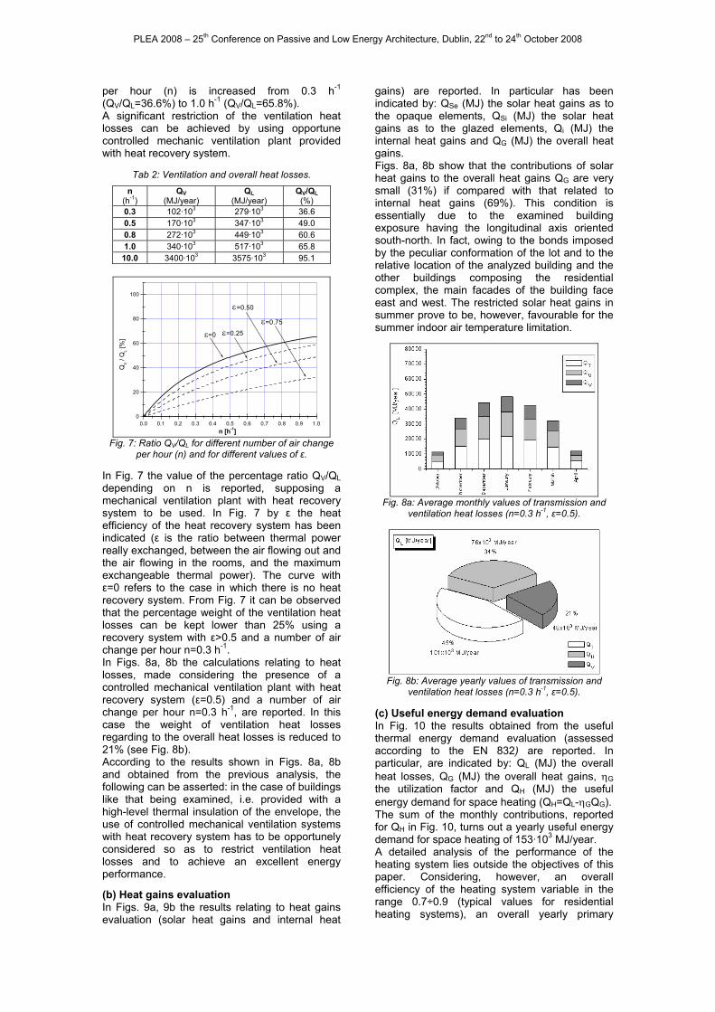
n [h-1] Fig. 7: Ratio QV/QL for different number of air change
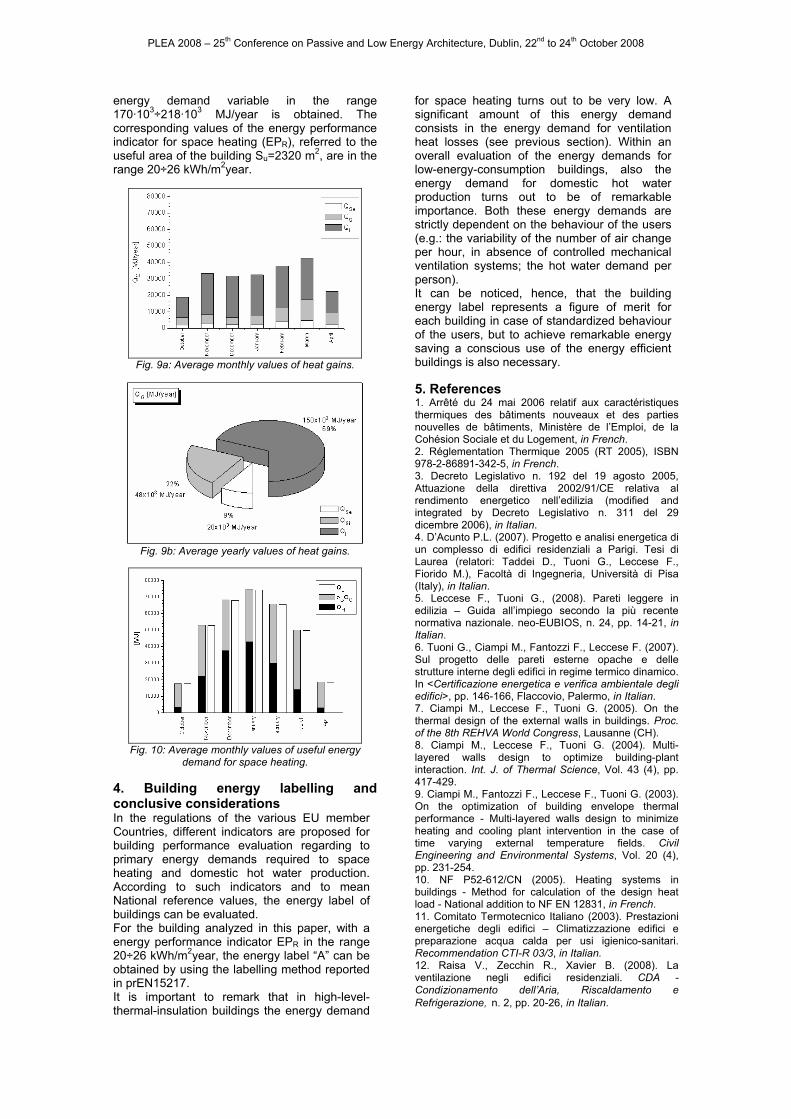
per hour (n) and for different values of ε. In Fig. 7 the value of the percentage ratio QV/QL depending on n is reported, supposing a mechanical ventilation plant with heat recovery system to be used. In Fig. 7 by ε the heat efficiency of the heat recovery system has been indicated (ε is the ratio between thermal power really exchanged, between the air flowing out and the air flowing in the rooms, and the maximum exchangeable thermal power). The curve with ε=0 refers to the case in which there is no heat recovery system. From Fig. 7 it can be observed that the percentage weight of the ventilation heat losses can be kept lower than 25% using a recovery system with ε>0.5 and a number of air change per hour n=0.3 h-1. In Figs. 8a, 8b the calculations relating to heat losses, made considering the presence of a controlled mechanical ventilation plant with heat recovery system (ε=0.5) and a number of air change per hour n=0.3 h-1, are reported. In this case the weight of ventilation heat losses regarding to the overall heat losses is reduced to 21% (see Fig. 8b). According to the results shown in Figs. 8a, 8b and obtained from the previous analysis, the following can be asserted: in the case of buildings like that being examined, i.e. provided with a high-level thermal insulation of the envelope, the use of controlled mechanical ventilation systems with heat recovery system has to be opportunely considered so as to restrict ventilation heat losses and to achieve an excellent energy performance. (b) Heat gains evaluation In Figs. 9a, 9b the results relating to heat gains evaluation (solar heat gains and internal heat
gains) are reported. In particular has been indicated by: QSe (MJ) the solar heat gains as to the opaque elements, QSi (MJ) the solar heat gains as to the glazed elements, Qi (MJ) the internal heat gains and QG (MJ) the overall heat gains. Figs. 8a, 8b show that the contributions of solar heat gains to the overall heat gains QG are very small (31%) if compared with that related to internal heat gains (69%). This condition is essentially due to the examined building exposure having the longitudinal axis oriented south-north. In fact, owing to the bonds imposed by the peculiar conformation of the lot and to the relative location of the analyzed building and the other buildings composing the residential complex, the main facades of the building face east and west. The restricted solar heat gains in summer prove to be, however, favourable for the summer indoor air temperature limitation.
Fig. 8a: Average monthly values of transmission and
ventilation heat losses (n=0.3 h-1, ε=0.5).
Fig. 8b: Average yearly values of transmission and
ventilation heat losses (n=0.3 h-1, ε=0.5). (c) Useful energy demand evaluation In Fig. 10 the results obtained from the useful thermal energy demand evaluation (assessed according to the EN 832) are reported. In particular, are indicated by: QL (MJ) the overall heat losses, QG (MJ) the overall heat gains, ηG the utilization factor and QH (MJ) the useful energy demand for space heating (QH=QL-ηGQG). The sum of the monthly contributions, reported for QH in Fig. 10, turns out a yearly useful energy demand for space heating of 153·103 MJ/year. A detailed analysis of the performance of the heating system lies outside the objectives of this paper. Considering, however, an overall efficiency of the heating system variable in the range 0.7÷0.9 (typical values for residential heating systems), an overall yearly primary
PLEA 2008 – 25th Conference on Passive and Low Energy Architecture, Dublin, 22nd to 24th October 2008
energy demand variable in the range 170·103÷218·103 MJ/year is obtained. The corresponding values of the energy performance indicator for space heating (EPR), referred to the useful area of the building Su=2320 m2, are in the range 20÷26 kWh/m2year.
Fig. 9a: Average monthly values of heat gains.
Fig. 9b: Average yearly values of heat gains.
Fig. 10: Average monthly values of useful energy
demand for space heating. 4. Building energy labelling and conclusive considerations In the regulations of the various EU member Countries, different indicators are proposed for building performance evaluation regarding to primary energy demands required to space heating and domestic hot water production. According to such indicators and to mean National reference values, the energy label of buildings can be evaluated. For the building analyzed in this paper, with a energy performance indicator EPR in the range 20÷26 kWh/m2year, the energy label “A” can be obtained by using the labelling method reported in prEN15217. It is important to remark that in high-level-thermal-insulation buildings the energy demand
for space heating turns out to be very low. A significant amount of this energy demand consists in the energy demand for ventilation heat losses (see previous section). Within an overall evaluation of the energy demands for low-energy-consumption buildings, also the energy demand for domestic hot water production turns out to be of remarkable importance. Both these energy demands are strictly dependent on the behaviour of the users (e.g.: the variability of the number of air change per hour, in absence of controlled mechanical ventilation systems; the hot water demand per person). It can be noticed, hence, that the building energy label represents a figure of merit for each building in case of standardized behaviour of the users, but to achieve remarkable energy saving a conscious use of the energy efficient buildings is also necessary. 5. References 1. Arrêté du 24 mai 2006 relatif aux caractéristiques thermiques des bâtiments nouveaux et des parties nouvelles de bâtiments, Ministère de l’Emploi, de la Cohésion Sociale et du Logement, in French. 2. Réglementation Thermique 2005 (RT 2005), ISBN 978-2-86891-342-5, in French. 3. Decreto Legislativo n. 192 del 19 agosto 2005, Attuazione della direttiva 2002/91/CE relativa al rendimento energetico nell’edilizia (modified and integrated by Decreto Legislativo n. 311 del 29 dicembre 2006), in Italian. 4. D’Acunto P.L. (2007). Progetto e analisi energetica di un complesso di edifici residenziali a Parigi. Tesi di Laurea (relatori: Taddei D., Tuoni G., Leccese F., Fiorido M.), Facoltà di Ingegneria, Università di Pisa (Italy), in Italian. 5. Leccese F., Tuoni G., (2008). Pareti leggere in edilizia – Guida all’impiego secondo la più recente normativa nazionale. neo-EUBIOS, n. 24, pp. 14-21, in Italian. 6. Tuoni G., Ciampi M., Fantozzi F., Leccese F. (2007). Sul progetto delle pareti esterne opache e delle strutture interne degli edifici in regime termico dinamico. In <Certificazione energetica e verifica ambientale degli edifici>, pp. 146-166, Flaccovio, Palermo, in Italian. 7. Ciampi M., Leccese F., Tuoni G. (2005). On the thermal design of the external walls in buildings. Proc. of the 8th REHVA World Congress, Lausanne (CH). 8. Ciampi M., Leccese F., Tuoni G. (2004). Multi-layered walls design to optimize building-plant interaction. Int. J. of Thermal Science, Vol. 43 (4), pp. 417-429. 9. Ciampi M., Fantozzi F., Leccese F., Tuoni G. (2003). On the optimization of building envelope thermal performance - Multi-layered walls design to minimize heating and cooling plant intervention in the case of time varying external temperature fields. Civil Engineering and Environmental Systems, Vol. 20 (4), pp. 231-254. 10. NF P52-612/CN (2005). Heating systems in buildings - Method for calculation of the design heat load - National addition to NF EN 12831, in French. 11. Comitato Termotecnico Italiano (2003). Prestazioni energetiche degli edifici – Climatizzazione edifici e preparazione acqua calda per usi igienico-sanitari. Recommendation CTI-R 03/3, in Italian. 12. Raisa V., Zecchin R., Xavier B. (2008). La ventilazione negli edifici residenziali. CDA - Condizionamento dell’Aria, Riscaldamento e Refrigerazione, n. 2, pp. 20-26, in Italian.