Embed Size (px)
Citation preview
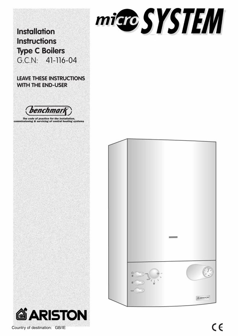
InstallationInstructionsType C BoilersG.C.N: 41-116-04
LEAVE THESE INSTRUCTIONSWITH THE END-USER
Country of destination: GB/IE
This manual is an integral and essential part of the product. It should be kept with theappliance so that it can be consulted by the user and our authorised personnel.
Please carefully read the instructionsand notices about the unit contained inthis manual, as they provide importantinformation regarding the safeinstallation, use and maintenance of theproduct.
For operating instructions pleaseconsult the separate User’s Manual.
1. GENERAL INFORMATION
User’sManual
2
TABLE OF CONTENTS 1. GENERAL INFORMATION
1.1 GENERAL INSTRUCTIONS
1.2 OVERALL VIEW
2. INSTALLATION
2.1 DELIVERY
2.2 REFERENCE STANDARDS
2.3 SITING THE APPLIANCE
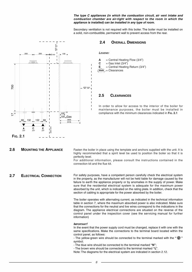
2.4 OVERALL DIMENSIONS
2.5 CLEARANCES
2.6 MOUNTING THE APPLIANCE
2.7 ELECTRICAL CONNECTION
2.8 GAS CONNECTION
2.9 WATER CONNECTIONS
2.10 FLUE CONNECTION
2.11 ROOM THERMOSTAT CONNECTION
2.12 ELECTRICAL DIAGRAMS
2.13 GAS AND WATER CIRCUITS
3. D.H.W. STORAGE CYLINDER
3.1 2 PORT AND 3 PORT VALVE INSTALLATIONS
3.2 DOMESTIC HOT WATER PRIORITY KIT
4. COMMISSIONING
4.1 INITIAL PREPARATION
4.2 CONTROL PANEL
4.3 REMOVING THE FRONT PANEL
4.4 INITIAL START UP
4.5 OPERATIONAL ADJUSTMENTS
4.6 COMBUSTION ANALYSIS
4.7 FUME DISCHARGE MONITORING
4.8 DRAINING THE SYSTEM
5. GAS ADJUSTMENTS
GAS ADJUSTMENT TABLE
5.1 CHANGING THE TYPE OF GAS
6. MAINTENANCE
7. TECHNICAL INFORMATION
3
1.1 GENERAL INSTRUCTIONS Read the instructions and recommendations in these Installation Instructionscarefully to ensure proper installation, use and maintenance of the appliance.
Keep this manual in a safe place. You may need it for your own reference while ourServicing Centre technicians or your installer may need to consult it in the future.
This is an appliance for the production of central heating (C.H.).
This appliance must be used only for the purpose for which it is designed.The manufacturer declines all liability for damage caused by improper or negligentuse.
No asbestos or other hazardous materials have been used in the fabrication of thisproduct.
Before connecting the appliance, check that the information shown on the dataplate and the table in section 7 comply with the electric, water and gas mains of theproperty.You will find the data plate on the reverse of the control panel.The gas with which this appliance operates is also shown on the label at the bottomof the boiler.
Do not install this appliance in a damp environment or close to equipment whichspray water or other liquids.Do not place objects on the appliance.Do not allow children or inexperienced persons to use the appliance withoutsupervision.
If you smell gas in the room, do not turn on light switches, use the telephone or anyother object which might cause sparks.Open doors and windows immediately to ventilate the room.Shut the gas mains tap (at or adjacent to the gas meter) or the valve of the gascylinder and call your Gas Supplier immediately.If you are going away for a long period of time, remember to shut the mains gas tapor the gas cylinder valve.
Always disconnect the appliance either by unplugging it from the mains or turningoff the mains switch before cleaning the appliance or carrying out maintenance.
In the case of faults or failure, switch off the appliance and turn off the gas tap. Donot tamper with the appliance.For repairs, call your local Authorised Servicing Centre and request the use oforiginal spare parts. For in-guarantee repairs contact MTS.
Check the following at least once a year:1 - Check the seals for the water connections; replace any faulty seals.2 - Check the gas seals; replace any faulty gas seals.3 - Visual check of the entire unit.4 - Visual check of the combustion process or analysis of combustion by-products
(see section 4.5) and cleaning of the burner if needed.5 - If called for by point. 3, dismantling and cleaning of the combustion
chamber.6 - If called for by point. 4, dismantling and cleaning of the burner jets.7 - Visual check of the primary heat exchanger:
- check for overheating in the blade assembly;- clean the exhaust fan if needed.
8 - Adjustment of the flow rate of the gas: flow rate for lighting, partial load and fullload.
9 - Check of the heating safety systems:- safety device for maximum temperature (overheat thermostat);- safety device for maximum pressure (safety valve).
10- Check of the gas safety systems:- safety device for lack of gas or flame ionisation (detection electrode);- safety device for gas cock.
11- Check of the electrical connection (make sure it complies with the instructionsin the manual).
12- General check of the combustion by-products of the discharge/ventilationsystem.
13- Check of the general performance of the unit.
4
The technical information and instructions provided herein below are intended for theinstaller / Servicing Technician so that the unit may be installed and servicedcorrectly and safely.
There will be two items:1 - The fully assembled boiler2 - A separately boxed connection ki
WATER REGULATIONSIn GB it is necessary to comply with the Water Supply (Water Fittings) Regulations 1999,for Scotland, The Water Bylaws 2000, Scotland. The Genus 30 Plus is an approvedproduct under the Water Regulations.
To comply with the Water Regulations, you attention is drawn to The Water Regulationsguide published by the Water Regulations Advisory Scheme (WRAS) gives full details ofthe requirements.
In IE, the requirements given in the current edition of I.S.813 and the current BuildingRegulations must be followed.
The installation of this appliance must be in accordance with the relevantrequirements of the Local Building Regulations, the current I.E.E. Wiring Regulations,the bylaws of the local water authority, in Scotland, in accordance with the BuildingStandards (Scotland) Regulation and Health and Safety document No. 635“Electricity at work regulations 1989” and in the Republic of Ireland with the currentedition of I.S. 813, the Local Building Regulations (IE).
C.O.S.H.H.Materials used in the manufacture of this appliance are non-hazardous and nospecial precautions are required when servicing.Installation should also comply with the following British Standard Codes of Practice:
2. INSTALLATION
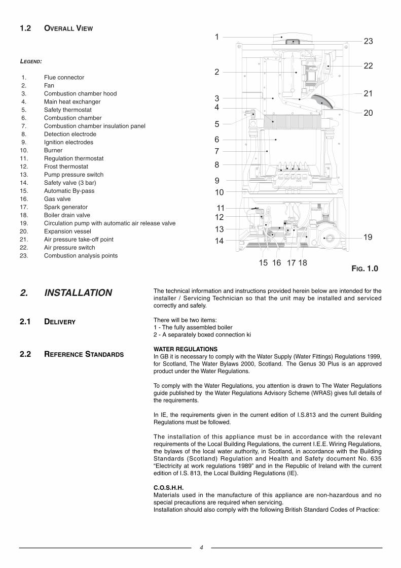
1.2 OVERALL VIEW
FIG. 1.0
LEGEND:
1. Flue connector2. Fan3. Combustion chamber hood4. Main heat exchanger5. Safety thermostat6. Combustion chamber7. Combustion chamber insulation panel8. Detection electrode9. Ignition electrodes10. Burner 11. Regulation thermostat12. Frost thermostat13. Pump pressure switch14. Safety valve (3 bar)15. Automatic By-pass16. Gas valve17. Spark generator18. Boiler drain valve19. Circulation pump with automatic air release valve20. Expansion vessel21. Air pressure take-off point22. Air pressure switch23. Combustion analysis points
2.2 REFERENCE STANDARDS
2.1 DELIVERY
5
and in the Republic of Ireland in accordance with the following Codes of Practice:
WARNING!!The addition of anything that may interfere with the normal operation of the appliancewithout express written permission of the manufacturer or his agent could invalidatethe warranty. In GB this could also infringe the GAS SAFETY(Installation and Use)REGULATIONS.
In the Republic of Ireland the installation and initial start up of the appliance must becarried out by a Competent Person in accordance with the current edition of I.S.813“Domestic Gas Installations”, the current Building Regulations, reference should alsobe made to the current ETCI rules for electrical installation.
The appliance may be installed in any room or indoor area, although particularattention is drawn to the requirements of the current I.E.E. Wiring Regulations, inScotland, the electrical provisions of the Building Regulations applicable in Scotland,and in the Republic of Ireland, the current edition of I.S.813, with respect to theinstallation of the combined appliance in a room containing a bath or shower. Thelocation of the boiler in a room containing a bath or shower should only beconsidered if there is no alternative.
Where a room-sealed appliance is installed in a room containing a bath orshower reference should be made to the relevant requirements.
In GB this is the current I.E.E. WIRING REGULATIONS and BUILDINGREGULATIONS. In IE reference should be made to the current edition of I.S.813and the current ETCI rules.
If the boiler is to be sited into a timber framed building, reference must be made tothe current edition of the Institution of Gas Engineers Publication IGE/UP/7 (GasInstallations in Timber Framed Housing).
The location must permit adequate space for servicing and air circulation around theappliance as indicated in Section 2.5.The location must permit the provision of an adequate flue and termination.For unusual locations special procedures may be necessary.BS 6798-1987 gives detailed guidance on this aspect.A compartment used to enclose the appliance must be designed specifically for thispurpose. No specific ventilation requirements are needed for the installation within acupboard.
This appliance is not suitable for outdoor installation.
BS 7593 Treatment of water in domestic hot water central heatingsystems
BS 5546 Installation of hot water supplies for domestic purposesBS 5440-1 FluesBS 5440-2 Air supplyBS 5449 Forced circulation hot water systemsBS 6798 Installation of gas fired hot water boilers of rated input not
exceeding 60kWBS 6891 Installation of low pressure gas pipe up to 28mmBS 7671 IEE wiring regulationsBS 7074 Specification for expansion vesselsBS 5482 Installation of L.P.G.
I.S. 813 Domestic Gas Installations
The following BS Standards give valuable information;
BS 5546 Installation of hot water supplies for domestic purposesBS 5449 Forced circulation hot water systemsBS 7074 Specification for expansion vesselsBS 7593 Treatment of water in domestic hot water central heating
systems
2.3 SITING THE APPLIANCE
For safety purposes, have a competent person carefully check the electrical systemin the property, as the manufacturer will not be held liable for damage caused by thefailure to earth the appliance properly or by anomalies in the supply of power. Makesure that the residential electrical system is adequate for the maximum powerabsorbed by the unit, which is indicated on the rating plate. In addition, check that thesection of cabling is appropriate for the power absorbed by the boiler.
The boiler operates with alternating current, as indicated in the technical informationtable in section 7, where the maximum absorbed power is also indicated. Make surethat the connections for the neutral and live wires correspond to the indications in thediagram. The appliance electrical connections are situated on the reverse of thecontrol panel under the inspection cover (see the servicing manual for furtherinformation)
IMPORTANT!In the event that the power supply cord must be changed, replace it with one with thesame specifications. Make the connections to the terminal board located within thecontrol panel, as follows:- The yellow-green wire should be connected to the terminal marked with the “ ”symbol;- The blue wire should be connected to the terminal marked “N”;- The brown wire should be connected to the terminal marked “L”.Note: The diagrams for the electrical system are indicated in section 2.12.
Fasten the boiler in place using the template and anchors supplied with the unit. It ishighly recommended that a spirit level be used to position the boiler so that it isperfectly level.For additional information, please consult the instructions contained in theconnection kit and the flue kit.
2.7 ELECTRICAL CONNECTION
2.6 MOUNTING THE APPLIANCE
132 132
C E
400
mm
300
mm
60 mm
450 mm
LEGEND:
A = Central Heating Flow (3/4”)C = Gas Inlet (3/4”)E = Central Heating Return (3/4”)mm = Clearances
2.4 OVERALL DIMENSIONS
In order to allow for access to the interior of the boiler formaintenance purposes, the boiler must be installed incompliance with the minimum clearances indicated in FIG. 2.1
2.5 CLEARANCES
FIG. 2.1
6
The type C appliances (in which the combustion circuit, air vent intake andcombustion chamber are air-tight with respect to the room in which theappliance is installed) can be installed in any type of room.
Secondary ventilation is not required with this boiler. The boiler must be installed ona solid, non-combustible, permanent wall to prevent access from the rear.
7
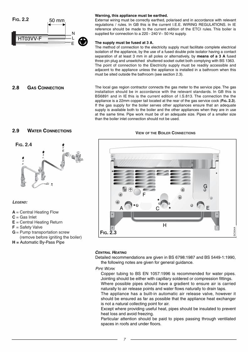
Warning, this appliance must be earthed.External wiring must be correctly earthed, polarised and in accordance with relevantregulations / rules. In GB this is the current I.E.E. WIRING REGULATIONS. In IEreference should be made to the current edition of the ETCI rules. This boiler issupplied for connection to a 220 - 240 V~ 50 Hz supply.
The supply must be fused at 3 A.The method of connection to the electricity supply must facilitate complete electricalisolation of the appliance, by the use of a fused double pole isolator having a contactseparation of at least 3 mm in all poles or alternatively, by means of a 3 A fusedthree pin plug and unswitched shuttered socket outlet both complying with BS 1363.The point of connection to the Electricity supply must be readily accessible andadjacent to the appliance unless the appliance is installed in a bathroom when thismust be sited outside the bathroom (see section 2.3).
ELN
FIG. 2.2
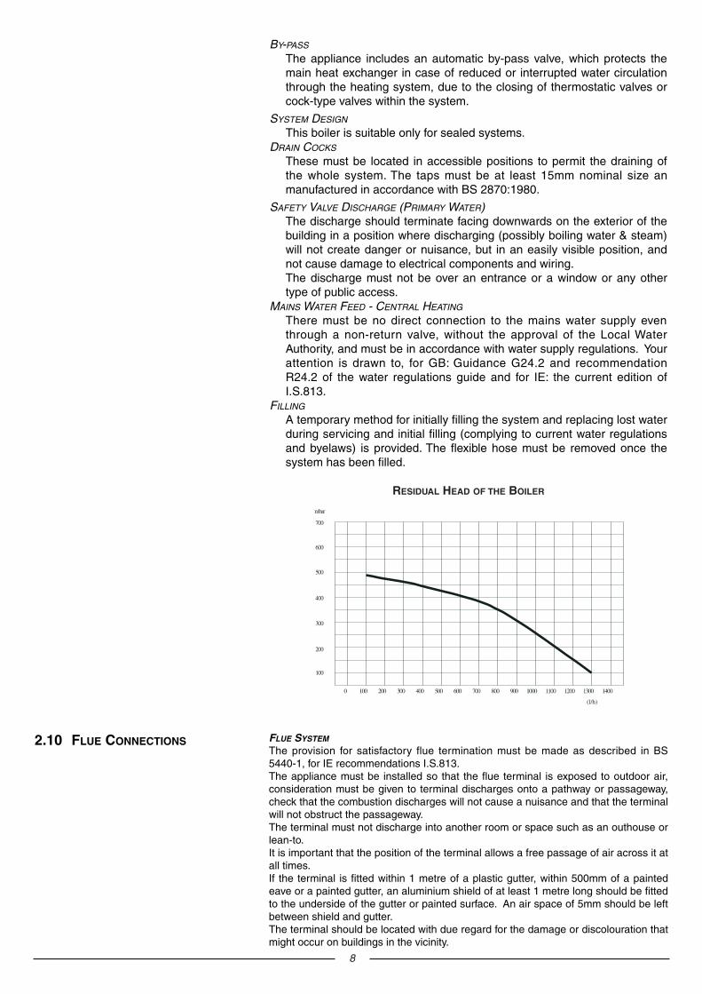
2.9 WATER CONNECTIONS
FIG. 2.4
VIEW OF THE BOILER CONNECTIONS
FIG. 2.3
A
G
LEGEND:
A = Central Heating FlowC = Gas InletE = Central Heating ReturnF = Safety ValveG = Pump transportation screw
(remove before igniting the boiler)H = Automatic By-Pass Pipe
F
H
C E
SC
004A
2.8 GAS CONNECTION The local gas region contractor connects the gas meter to the service pipe. The gasinstallation should be in accordance with the relevant standards. In GB this isBS6891 and in IE this is the current edition of I.S.813. The connection the theappliance is a 22mm copper tail located at the rear of the gas service cock (FIG. 2.3).If the gas supply for the boiler serves other appliances ensure that an adequatesupply is available both to the boiler and the other appliances when they are in useat the same time. Pipe work must be of an adequate size. Pipes of a smaller sizethan the boiler inlet connection should not be used.
CENTRAL HEATING
Detailed recommendations are given in BS 6798:1987 and BS 5449-1:1990,the following notes are given for general guidance.
PIPE WORK
Copper tubing to BS EN 1057:1996 is recommended for water pipes.Jointing should be either with capillary soldered or compression fittings.Where possible pipes should have a gradient to ensure air is carriednaturally to air release points and water flows naturally to drain taps.The appliance has a built-in automatic air release valve, however itshould be ensured as far as possible that the appliance heat exchangeris not a natural collecting point for air.Except where providing useful heat, pipes should be insulated to preventheat loss and avoid freezing.Particular attention should be paid to pipes passing through ventilatedspaces in roofs and under floors.
8
BY-PASS
The appliance includes an automatic by-pass valve, which protects themain heat exchanger in case of reduced or interrupted water circulationthrough the heating system, due to the closing of thermostatic valves orcock-type valves within the system.
SYSTEM DESIGN
This boiler is suitable only for sealed systems.DRAIN COCKS
These must be located in accessible positions to permit the draining ofthe whole system. The taps must be at least 15mm nominal size anmanufactured in accordance with BS 2870:1980.
SAFETY VALVE DISCHARGE (PRIMARY WATER)The discharge should terminate facing downwards on the exterior of thebuilding in a position where discharging (possibly boiling water & steam)will not create danger or nuisance, but in an easily visible position, andnot cause damage to electrical components and wiring.The discharge must not be over an entrance or a window or any othertype of public access.
MAINS WATER FEED - CENTRAL HEATING
There must be no direct connection to the mains water supply eventhrough a non-return valve, without the approval of the Local WaterAuthority, and must be in accordance with water supply regulations. Yourattention is drawn to, for GB: Guidance G24.2 and recommendationR24.2 of the water regulations guide and for IE: the current edition ofI.S.813.
FILLING
A temporary method for initially filling the system and replacing lost waterduring servicing and initial filling (complying to current water regulationsand byelaws) is provided. The flexible hose must be removed once thesystem has been filled.
RESIDUAL HEAD OF THE BOILER
2.10 FLUE CONNECTIONS FLUE SYSTEM
The provision for satisfactory flue termination must be made as described in BS5440-1, for IE recommendations I.S.813.The appliance must be installed so that the flue terminal is exposed to outdoor air,consideration must be given to terminal discharges onto a pathway or passageway,check that the combustion discharges will not cause a nuisance and that the terminalwill not obstruct the passageway.The terminal must not discharge into another room or space such as an outhouse orlean-to.It is important that the position of the terminal allows a free passage of air across it atall times.If the terminal is fitted within 1 metre of a plastic gutter, within 500mm of a paintedeave or a painted gutter, an aluminium shield of at least 1 metre long should be fittedto the underside of the gutter or painted surface. An air space of 5mm should be leftbetween shield and gutter.The terminal should be located with due regard for the damage or discolouration thatmight occur on buildings in the vicinity.

9
IMPORTANT!
For all flue systems, a restrictor mustalways be inserted into the boiler’sflue connector; the restrictor must beØ 44 in diameter depending on thelength of piping indicated in TABLE
2.1.
FIG 2.9 and FIG 2.10 illustrate some ofthe various designs for coaxial or twinpipe flue systems.For fur ther information ondischarge/ventilation accessories, seethe FLUE PIPE ACCESSORIES MANUAL.
COAXIAL SYSTEMS
FIG. 2.9
In cold or humid weather water vapour may condense on leaving the flue terminal.The effect of such “steaming” must be considered.If the terminal is less than 2 metres above a balcony, above ground or above a flatroof to which people have access, then a suitable terminal guard must be fitted.When ordering a terminal guard, quote the appliance model number.
A suitable terminal guard is available from:TOWER FLUE COMPONENTSMorley RoadTonbridgeKent TN9 1RAThe minimum acceptable spacing from the terminal to obstructions and ventilationopenings are specified in FIG. 2.5.
Ø 60/100 mm
FIG. 2.6
The boiler is designed to be connected to a coaxial flue discharge system.
TERMINAL POSITION mmA - Directly above or below an openable window
or other opening 300B - Below gutters, solid pipes or drain pipes 75C - Below eaves 200D - Below balconies or car-port roof 200E - From vertical drain pipes and soil pipes 150F - From internal or external corners 300G - Above ground or balcony level 300H - From a surface facing a terminal 600I - From a terminal facing a terminal 1200J - From an opening in the car port
(e.g. door, window) into dwelling 1200K - Vertically from a terminal in the same wall 1500L - Horizontally from a terminal in the same wall 300M - Horizontally from an opening window 300N - Fixed by vertical flue terminal
FIG. 2.5
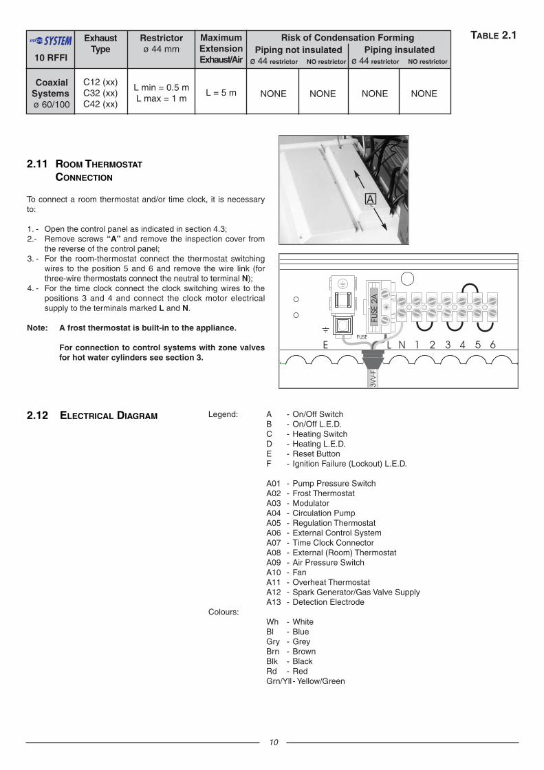
ExhaustType
C12 (xx)C32 (xx)C42 (xx)
Restrictorø 44 mm
L min = 0.5 mL max = 1 m
MaximumExtensionExhaust/Air
L = 5 m
Risk of Condensation Forming
CoaxialSystemsø 60/100
Piping not insulatedø 44 restrictor NO restrictor
NONE NONE
Piping insulatedø 44 restrictor NO restrictor
NONE NONE
TABLE 2.1
10 RFFI
To connect a room thermostat and/or time clock, it is necessaryto:
1. - Open the control panel as indicated in section 4.3;2.- Remove screws “A” and remove the inspection cover from
the reverse of the control panel;3. - For the room-thermostat connect the thermostat switching
wires to the position 5 and 6 and remove the wire link (forthree-wire thermostats connect the neutral to terminal N);
4. - For the time clock connect the clock switching wires to thepositions 3 and 4 and connect the clock motor electricalsupply to the terminals marked L and N.
Note: A frost thermostat is built-in to the appliance.
For connection to control systems with zone valvesfor hot water cylinders see section 3.
2.11 ROOM THERMOSTAT
CONNECTION
A
10
2.12 ELECTRICAL DIAGRAM Legend: A - On/Off SwitchB - On/Off L.E.D.C - Heating SwitchD - Heating L.E.D.E - Reset ButtonF - Ignition Failure (Lockout) L.E.D.
A01 - Pump Pressure SwitchA02 - Frost ThermostatA03 - ModulatorA04 - Circulation PumpA05 - Regulation ThermostatA06 - External Control SystemA07 - Time Clock ConnectorA08 - External (Room) ThermostatA09 - Air Pressure SwitchA10 - FanA11 - Overheat ThermostatA12 - Spark Generator/Gas Valve SupplyA13 - Detection Electrode
Colours:Wh - WhiteBl - BlueGry - GreyBrn - BrownBlk - BlackRd - RedGrn/Yll - Yellow/Green
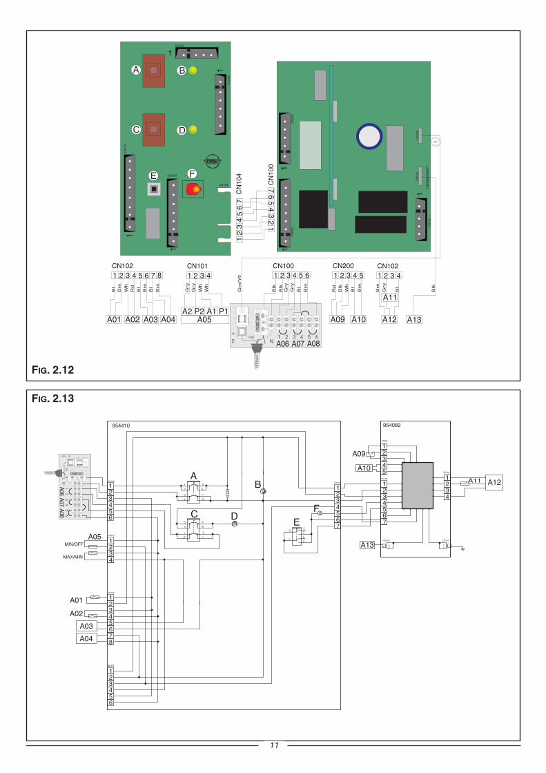
FIG. 2.13
11
FIG. 2.12
12
12
3
4
567
89
10
11 12
1314
15
16
17
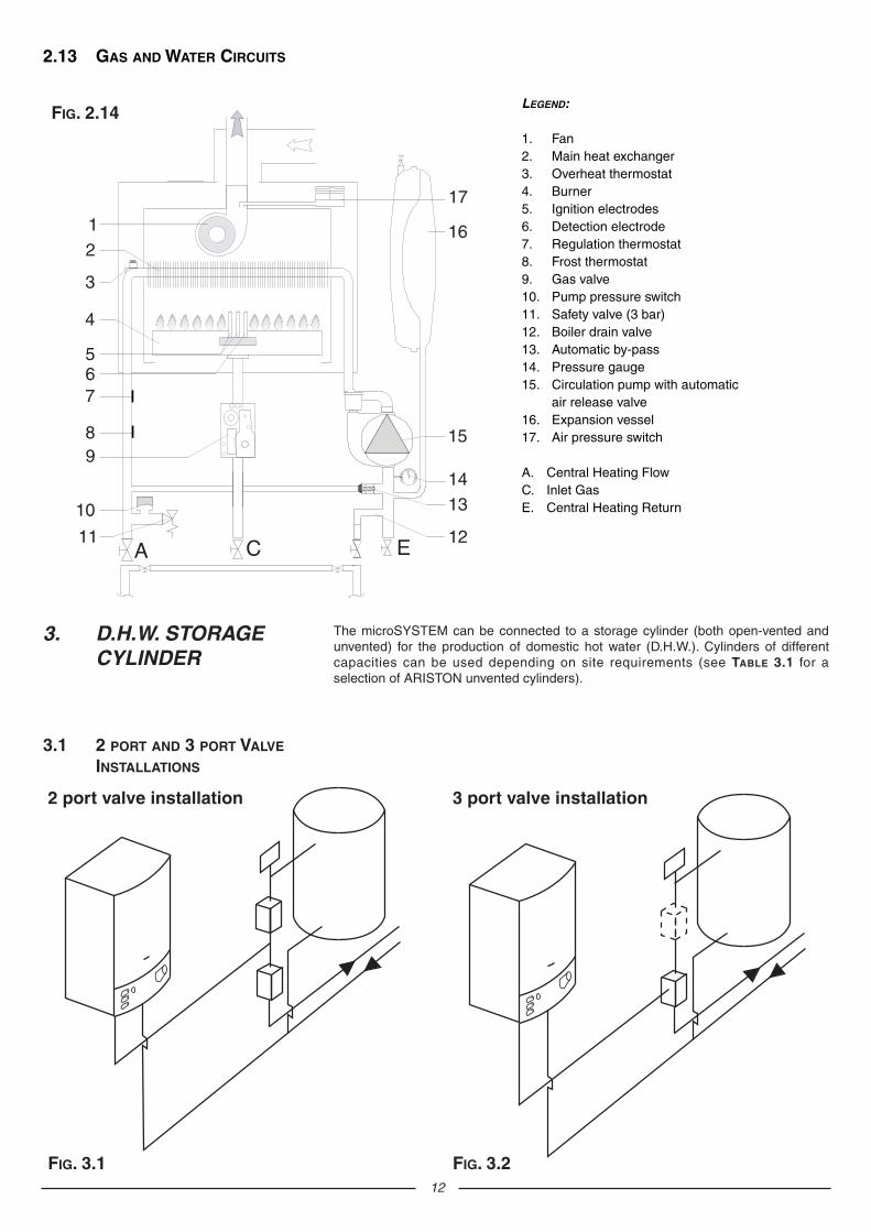
LEGEND:
1. Fan2. Main heat exchanger3. Overheat thermostat 4. Burner 5. Ignition electrodes6. Detection electrode7. Regulation thermostat 8. Frost thermostat9. Gas valve10. Pump pressure switch11. Safety valve (3 bar)12. Boiler drain valve13. Automatic by-pass 14. Pressure gauge15. Circulation pump with automatic
air release valve16. Expansion vessel17. Air pressure switch
A. Central Heating FlowC. Inlet GasE. Central Heating Return
2.13 GAS AND WATER CIRCUITS
FIG. 2.14
3. D.H.W. STORAGECYLINDER
The microSYSTEM can be connected to a storage cylinder (both open-vented andunvented) for the production of domestic hot water (D.H.W.). Cylinders of differentcapacities can be used depending on site requirements (see TABLE 3.1 for aselection of ARISTON unvented cylinders).
FIG. 3.2
3 port valve installation
FIG. 3.1
2 port valve installation
3.1 2 PORT AND 3 PORT VALVE
INSTALLATIONS
13
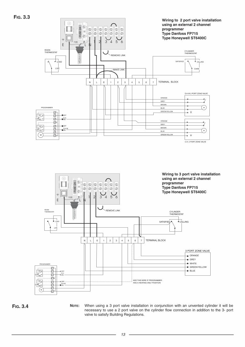
Wiring to 3 port valve installation using an external 2 channelprogrammer Type Danfoss FP715 Type Honeywell ST6400C
FIG. 3.4 NOTE: When using a 3 port valve installation in conjunction with an unvented cylinder it will benecessary to use a 2 port valve on the cylinder flow connection in addition to the 3- portvalve to satisfy Building Regulations.
Wiring to 2 port valve installation using an external 2 channelprogrammer Type Danfoss FP715 Type Honeywell ST6400C
FIG. 3.3
14
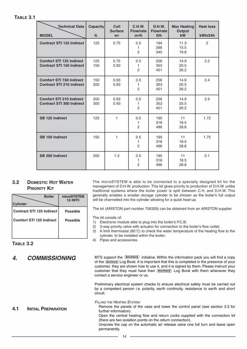
Technical Data Capacity Coil C.H.W. D.H.W. Max Heating Heat IossSurface Flow/rate Flow/rate Output
MODEL It. m2 m3/h It/h kW kWh/24h
Contract STI 125 Indirect 125 0.75 0.5 194 11.3 21 266 15.52 340 19.8
Comfort STI 125 Indirect 125 0.75 0.5 256 14.9 2.2Contract STI 150 Indirect 150 0.93 1 353 20.5
2 451 26.2
Comfort STI 150 Indirect 150 0.93 0.5 256 14.9 2.4Contract STI 210 indirect 200 0.93 1 353 20.5
2 451 26.2
Comfort STI 210 Indirect 200 0.93 0.5 256 14.9 2.9Contract STI 300 Indirect 300 0.93 1 353 20.5
2 451 26.2
SB 125 Indirect 125 1 0.5 190 11 1.721 318 18.52 496 28.8
SB 150 Indirect 150 1 0.5 190 11 1.751 318 18.52 496 28.8
SB 200 Indirect 200 1.3 0.5 190 11 2.11 318 18.52 496 28.8
TABLE 3.1
Boiler microSYSTEM10 RFFI
Cylinder
Possible
Possible
The microSYSTEM is able to be connected to a specially designed kit for themanagement of D.H.W. production. This kit gives priority to production of D.H.W. unliketraditional systems where the boiler power is split between C.H. and D.H.W. Thisgenerally enables a smaller storage cylinder to be chosen as the boiler’s full outputwill be channelled into the cylinder allowing for a quick heat-up.
The kit (ARISTON part number 706329) can be obtained from an ARISTON supplier.
The kit consits of:1) Electronic module able to plug into the boiler’s P.C.B;2) 3-way priority valve with actuator for connection to the boiler’s flow outlet;3) A limit thermostat (80˚C) to check the water temperature of the heating flow to the
cylinder, to be installed within the boiler;4) Pipes and accessories.
Contract STI 125 Indirect
Comfort STI 125 Indirect
TABLE 3.2
3.2 DOMESTIC HOT WATER
PRIORITY KIT
MTS support the initiative. Within the information pack you will find a copyof the Log Book. It is important that this is completed in the presence of yourcustomer, they are shown how to use it, and it is signed by them. Please instruct yourcustomer that they must have their Log Book with them whenever theycontact a service engineer or us.
Preliminary electrical system checks to ensure electrical safety must be carried outby a competent person i.e. polarity, earth continuity, resistance to earth and shortcircuit.
FILLING THE HEATING SYSTEM:Remove the panels of the case and lower the control panel (see section 3.3 forfurther information).Open the central heating flow and return cocks supplied with the connection kit(there are two isolation points on the return connection).Unscrew the cap on the automatic air release valve one full turn and leave openpermanently.
4. COMMISSIONING
4.1 INITIAL PREPARATION
A
BCDEF
I LG HLEGEND:
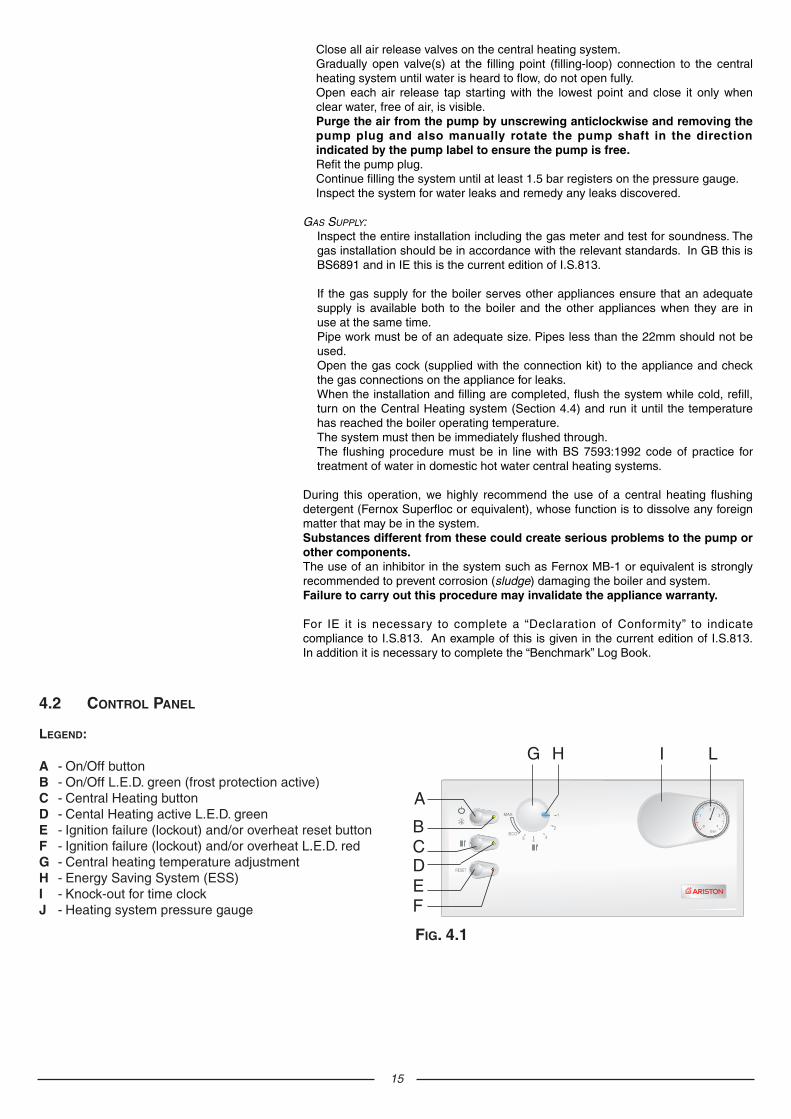
A - On/Off buttonB - On/Off L.E.D. green (frost protection active)C - Central Heating buttonD - Cental Heating active L.E.D. green E - Ignition failure (lockout) and/or overheat reset buttonF - Ignition failure (lockout) and/or overheat L.E.D. redG - Central heating temperature adjustmentH - Energy Saving System (ESS)I - Knock-out for time clock J - Heating system pressure gauge
4.2 CONTROL PANEL
FIG. 4.1
15
Close all air release valves on the central heating system.Gradually open valve(s) at the filling point (filling-loop) connection to the centralheating system until water is heard to flow, do not open fully.Open each air release tap starting with the lowest point and close it only whenclear water, free of air, is visible.Purge the air from the pump by unscrewing anticlockwise and removing thepump plug and also manually rotate the pump shaft in the directionindicated by the pump label to ensure the pump is free.Refit the pump plug.Continue filling the system until at least 1.5 bar registers on the pressure gauge.Inspect the system for water leaks and remedy any leaks discovered.
GAS SUPPLY:Inspect the entire installation including the gas meter and test for soundness. Thegas installation should be in accordance with the relevant standards. In GB this isBS6891 and in IE this is the current edition of I.S.813.
If the gas supply for the boiler serves other appliances ensure that an adequatesupply is available both to the boiler and the other appliances when they are inuse at the same time.Pipe work must be of an adequate size. Pipes less than the 22mm should not beused.Open the gas cock (supplied with the connection kit) to the appliance and checkthe gas connections on the appliance for leaks.When the installation and filling are completed, flush the system while cold, refill,turn on the Central Heating system (Section 4.4) and run it until the temperaturehas reached the boiler operating temperature.The system must then be immediately flushed through.The flushing procedure must be in line with BS 7593:1992 code of practice fortreatment of water in domestic hot water central heating systems.
During this operation, we highly recommend the use of a central heating flushingdetergent (Fernox Superfloc or equivalent), whose function is to dissolve any foreignmatter that may be in the system.Substances different from these could create serious problems to the pump orother components.The use of an inhibitor in the system such as Fernox MB-1 or equivalent is stronglyrecommended to prevent corrosion (sludge) damaging the boiler and system.Failure to carry out this procedure may invalidate the appliance warranty.
For IE it is necessary to complete a “Declaration of Conformity” to indicatecompliance to I.S.813. An example of this is given in the current edition of I.S.813.In addition it is necessary to complete the “Benchmark” Log Book.
B
4
5
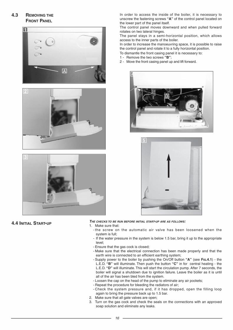
In order to access the inside of the boiler, it is necessary tounscrew the fastening screws “A” of the control panel located onthe lower part of the panel itself.The control panel moves downward and when pulled forwardrotates on two lateral hinges.The panel stays in a semi-horizontal position, which allowsaccess to the inner parts of the boiler.In order to increase the manoeuvring space, it is possible to raisethe control panel and rotate it to a fully horizontal position.
16
4.3 REMOVING THE
FRONT PANEL
1
2
3
A
To dismantle the front casing panel it is necessary to:1 - Remove the two screws “B”;2 - Move the front casing panel up and lift forward.
4.4 INITIAL START-UPTHE CHECKS TO BE RUN BEFORE INITIAL START-UP ARE AS FOLLOWS:1. Make sure that:
- the screw on the automatic air valve has been loosened when thesystem is full;
- If the water pressure in the system is below 1.5 bar, bring it up to the appropriatelevel;
- Ensure that the gas cock is closed;- Make sure that the electrical connection has been made properly and that the
earth wire is connected to an efficient earthing system;- Supply power to the boiler by pushing the On/Off button “A” (see FIG.4.1) - the
L.E.D. “B” will illuminate. Then push the button “C” in for central heating - theL.E.D. “D” will illuminate. This will start the circulation pump. After 7 seconds, theboiler will signal a shutdown due to ignition failure. Leave the boiler as it is untilall of the air has been bled from the system.
- Loosen the cap on the head of the pump to eliminate any air pockets;- Repeat the procedure for bleeding the radiators of air;- Check the system pressure and, if it has dropped, open the filling loop
again to bring the pressure back up to 1.5 bar.2. Make sure that all gate valves are open;3. Turn on the gas cock and check the seals on the connections with an approved
soap solution and eliminate any leaks.
17
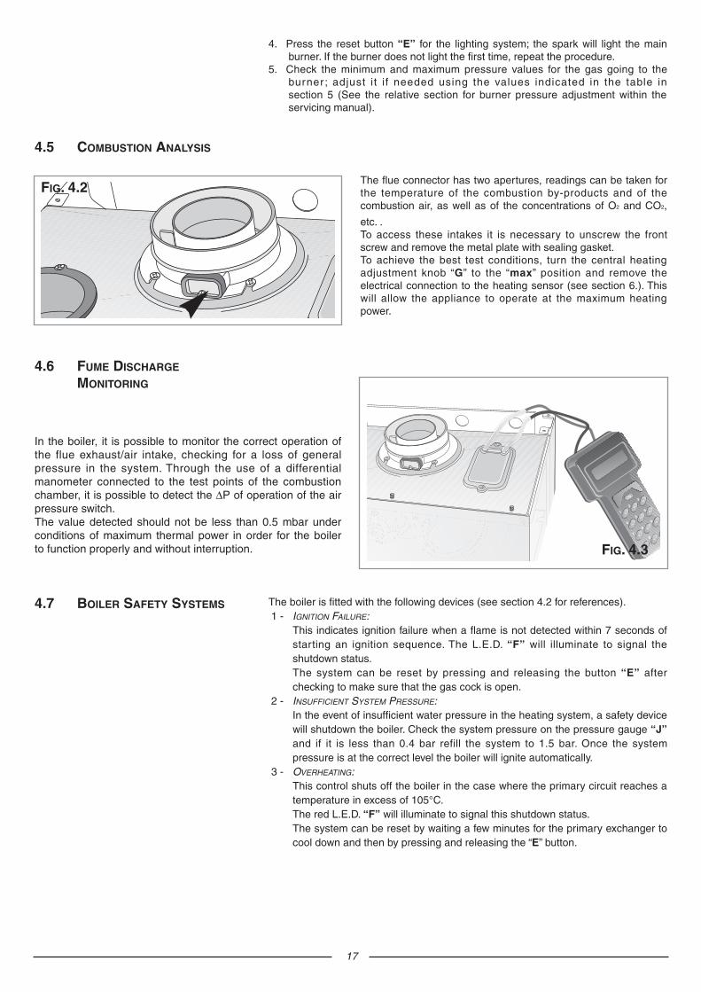
The flue connector has two apertures, readings can be taken forthe temperature of the combustion by-products and of thecombustion air, as well as of the concentrations of O2 and CO2,
etc. .To access these intakes it is necessary to unscrew the frontscrew and remove the metal plate with sealing gasket.To achieve the best test conditions, turn the central heatingadjustment knob “G” to the “max” position and remove theelectrical connection to the heating sensor (see section 6.). Thiswill allow the appliance to operate at the maximum heatingpower.
4.5 COMBUSTION ANALYSIS
FIG. 4.2
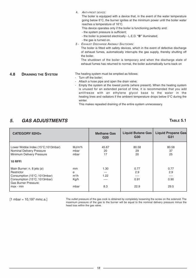
In the boiler, it is possible to monitor the correct operation ofthe flue exhaust/air intake, checking for a loss of generalpressure in the system. Through the use of a differentialmanometer connected to the test points of the combustionchamber, it is possible to detect the ∆P of operation of the airpressure switch.The value detected should not be less than 0.5 mbar underconditions of maximum thermal power in order for the boilerto function properly and without interruption.
4.6 FUME DISCHARGE
MONITORING
FIG. 4.3
4. Press the reset button “E” for the lighting system; the spark will light the mainburner. If the burner does not light the first time, repeat the procedure.
5. Check the minimum and maximum pressure values for the gas going to theburner ; adjust i t i f needed using the values indicated in the table insection 5 (See the relative section for burner pressure adjustment within theservicing manual).
The boiler is fitted with the following devices (see section 4.2 for references).1 - IGNITION FAILURE:
This indicates ignition failure when a flame is not detected within 7 seconds ofstarting an ignition sequence. The L.E.D. “F” will illuminate to signal theshutdown status.The system can be reset by pressing and releasing the button “E” afterchecking to make sure that the gas cock is open.
2 - INSUFFICIENT SYSTEM PRESSURE:In the event of insufficient water pressure in the heating system, a safety devicewill shutdown the boiler. Check the system pressure on the pressure gauge “J”and if it is less than 0.4 bar refill the system to 1.5 bar. Once the systempressure is at the correct level the boiler will ignite automatically.
3 - OVERHEATING:This control shuts off the boiler in the case where the primary circuit reaches atemperature in excess of 105°C.The red L.E.D. “F” will illuminate to signal this shutdown status.The system can be reset by waiting a few minutes for the primary exchanger tocool down and then by pressing and releasing the “E” button.
4.7 BOILER SAFETY SYSTEMS
18
The heating system must be emptied as follows:- Turn off the boiler;- Attach a hose pipe and open the drain valve;- Empty the system at the lowest points (where present). When the heating system
is unused for an extended period of time, it is recommended that you addantifreeze with an ethylene glycol base to the water in theheating lines and radiators if the ambient temperature drops below 0°C during thewinter.This makes repeated draining of the entire system unnecessary.
4.8 DRAINING THE SYSTEM
The outlet pressure of the gas cock is obtained by completely loosening the screw on the solenoid. Themaximum pressure of the gas to the burner will be equal to the nominal delivery pressure minus thehead loss within the gas valve.
[1 mbar = 10,197 mmc.a.]
5. GAS ADJUSTMENTS
CATEGORY II2H3+ Methane GasG20
Liquid Butane GasG30
Liquid Propane GasG31
45.67 2017
1.30---
1.22----
8.3
80.58 2920
0.772.9----
0.91
22.9
80.58 3725
0.772.9----
0.90
29.5
TABLE 5.1
Lower Wobbe Index (15°C;1013mbar) MJ/m3hNominal Delivery Pressure mbarMinimum Delivery Pressure mbar
10 RFFI
Main Burner: n. 8 jets (ø) mmRestrictor ø Consumption (15°C; 1013mbar) m3/hConsumption (15°C; 1013mbar) Kg/hGas Burner Pressure:max - min mbar
4. ANTI-FROST DEVICE:The boiler is equipped with a device that, in the event of the water temperaturegoing below 6°C, the burner ignites at the minimum power until the boiler waterreaches a temperature of 16°C.This device operates only if the boiler is functioning perfectly and:- the system pressure is sufficient;- the boiler is powered electrically - L.E.D. “B” illuminated;- the gas is turned on.
5 - EXHAUST DISCHARGE ANOMALY SHUTDOWN:The boiler is fitted with safety devices, which in the event of defective dischargeof exhaust fumes, automatically interrupts the gas supply, thereby shutting offthe boiler.The shutdown of the boiler is temporary and when the discharge state ofexhaust fumes has returned to normal, the boiler automatically turns back on

19
It is recommended that the following inspections be carried out on the boiler atleast once a year:1 - Check the seals for the water connections; replace any faulty seals.2 - Check the gas seals; replace any faulty gas seals.3 - Visual check of the entire unit.4 - Visual check of the combustion process or analysis of combustion by-products
(see section 4.5) and cleaning of the burner if needed.5 - If called for by point. 3, dismantling and cleaning of the combustion chamber.6 - If called for by point. 4, dismantling and cleaning of the burner jets.7 - Visual check of the primary heat exchanger:
- check for overheating in the blade assembly;- clean the exhaust fan if needed.
8 - Adjustment of the flow rate of the gas: flow rate for lighting, partial load and full load.9 - Check of the heating safety systems:
- safety device for maximum temperature (overheat thermostat);- safety device for maximum pressure (safety valve).
10- Check of the gas safety systems:- safety device for lack of gas or flame ionisation (detection electrode);- safety device for gas cock.
11- Check of the electrical connection (make sure it complies with the instructionsin the manual).
12- General check of the combustion by-products of the discharge/ventilation system.13- Check of the general performance of the unit.
6. MAINTENANCE
The boiler can be converted to use either methane (natural) gas (G20)or LPG (G30 - G31) by an Authorised Service Centre.The operations that must be performed are the following:1. Replace the jets on the main burner (see table in section 5);2. Pay attention to put the gas restrictor if convert the boiler from NG to
GPL and to take it out when pass from LPG to NG;2. Adjust the maximum and minimum thermal capacity values for the boiler
(see table in section 5);3. Replace the gas rating plate;4. Adjust the maximum thermal power setting;5. Adjust the soft-light feature (open the cover of the regulation screw on the
gas valve (see FIG. 5.1). Rotate clockwise from min. to max. as perinstallation requirements).
5.1 CHANGING THE
TYPE OF GAS
VG
002A
b
FIG. 5.1
23 9
9 84
158
1 00
0 -
Sta
mp
a: b
ieffe
REC
AN
ATI
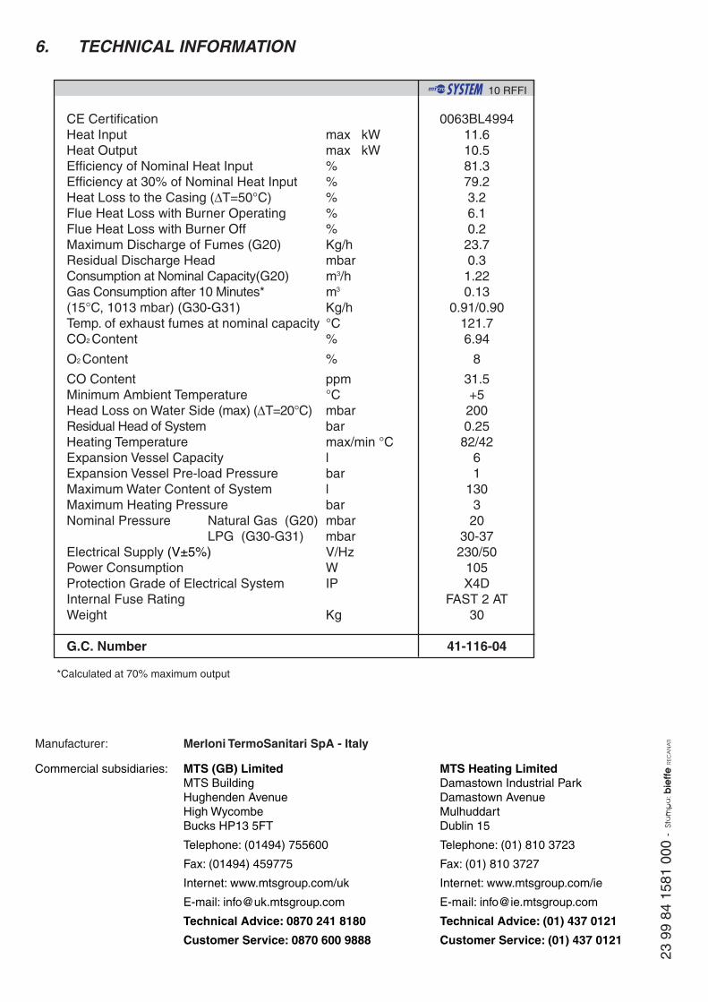
CE CertificationHeat Input max kWHeat Output max kWEfficiency of Nominal Heat Input %Efficiency at 30% of Nominal Heat Input %Heat Loss to the Casing (∆T=50°C) %Flue Heat Loss with Burner Operating %Flue Heat Loss with Burner Off %Maximum Discharge of Fumes (G20) Kg/hResidual Discharge Head mbarConsumption at Nominal Capacity(G20) m3/hGas Consumption after 10 Minutes* m3
(15°C, 1013 mbar) (G30-G31) Kg/hTemp. of exhaust fumes at nominal capacity °CCO2 Content %
O2 Content %
CO Content ppmMinimum Ambient Temperature °CHead Loss on Water Side (max) (∆T=20°C) mbarResidual Head of System barHeating Temperature max/min °CExpansion Vessel Capacity lExpansion Vessel Pre-load Pressure barMaximum Water Content of System lMaximum Heating Pressure barNominal Pressure Natural Gas (G20) mbar
LPG (G30-G31) mbarElectrical Supply (V±5%) V/HzPower Consumption WProtection Grade of Electrical System IPInternal Fuse RatingWeight Kg
G.C. Number
6. TECHNICAL INFORMATION
0063BL499411.610.581.379.23.26.10.223.70.31.220.13
0.91/0.90121.76.94
8
31.5+52000.2582/42
61
130320
30-37230/50
105X4D
FAST 2 AT30
41-116-04
10 RFFI
*Calculated at 70% maximum output
Commercial subsidiaries: MTS (GB) Limited MTS Heating LimitedMTS Building Damastown Industrial ParkHughenden Avenue Damastown AvenueHigh Wycombe MulhuddartBucks HP13 5FT Dublin 15
Telephone: (01494) 755600 Telephone: (01) 810 3723
Fax: (01494) 459775 Fax: (01) 810 3727
Internet: www.mtsgroup.com/uk Internet: www.mtsgroup.com/ie
E-mail: [email protected] E-mail: [email protected]
Technical Advice: 0870 241 8180 Technical Advice: (01) 437 0121
Customer Service: 0870 600 9888 Customer Service: (01) 437 0121
Manufacturer: Merloni TermoSanitari SpA - Italy