Embed Size (px)
Citation preview

580 SeriesFieldbus Electronics
Table of Contents
Features and Benefits 16
DeviceNet™ 17
Ethernet 18
Profibus DP 19
PROFINET 20
EtherCAT® 21
EtherNet/IP™ DLR 22
Dimensional Drawing - 580 Fieldbus Communication Assembly 23
How to Order - 580 Assembly Kit & 580 Electronics 24
How to Order Complete 580 Manifold Assemblies 25
Cables and Connectors 26-31

Information subject to change without notice. For ordering information or regarding your local sales office visit www.numatics.com.18
580SERIES
580 Fieldbus Communications ElectronicsWhy use Numatics Fieldbus communication electronics?
Modular Reality...
• No internal wiring simplifies assembly
• Power connector allows output power to be removed while inputs and communication are left active.
• IP65 protection
• 32 valve solenoids per manifold
580 Fieldbus - Electronics Made Easy!
Innovative Graphic Display is used for easy commissioning, visual status & diagnostics.
Graphic Display forconfiguration & diagnostics
Commissioning Capabilities
• Set network address (including IP & Subnet mask for Ethernet)
• Set baud rate• Set brightness• Set factory defaults
Visual Diagnostics
• Shorted and open load detection
• Shorted sensor/cable detection• Low & missing power detection• Self-test activation• Log of network errors
Supported Protocols
• DeviceNet™
• Ethernet/IP
• PROFIBUS DP
• PROFINET
• EtherCAT®
• EtherNet/IP™ DLR
DeviceNetTM is a trademark of ODVA.ControlNet is a trademark of ControlNet International, Ltd.PROFIBUS and PROFINET are registered trademarks of Profibus International.EtherCAT is a registered trademark of Beckhoff Automation GmbH.

Information subject to change without notice. For ordering information or regarding your local sales office visit www.numatics.com.19
580SERIES
DeviceNet™DeviceNet™ is an open bus fieldbus communication system developed by Allen-Bradley based on Controller Area Network (CAN) technology. The governing body for DeviceNet™ is the Open DeviceNet™ Vendors Association (ODVA). The ODVA controls the DeviceNet™ specification and oversees product conformance testing.
Numatics’ 580 nodes for DeviceNet™ have an integrated graphic display.
They have been tested and approved for conformance by the ODVA.
More information about DeviceNet™ and the ODVA can be obtained from the following website: www.odva.org
Technical DataElectrical Data Voltage Current
Node Power 24 VDC +/- 10% 0.050 Amps
BUS Power 11-25 VDC 0.050 Amps
Valves 24 VDC +/- 10% 4 Amps Maximum
Power Connector A-Coded 4 Pin M12 (Male)
Communication Connector A-Coded 5 Pin M12 (Male)
LEDs Module Status and Network Status
Operating Data
Temperature Range (ambient) -10º to 115º F (-23º to +46ºC)
Humidity 95% relative humidity, non-condensing
Vibration / Shock IEC 60068-2-27, IEC60068-2-6
Moisture Protection IP65 Certified
Description Replacement Part Number
DeviceNet™ communications module (node)
P580AEDN1010A00
Configuration Data
Graphic Display Display used for setting Node Address, Baud Rate, Fault / Idle Actions, and all other system settings.
Maximum Valve-Solenoid Outputs 32
Network Data
Supported Baud Rates 125K Baud, 250K Baud, 500K Baud, with Auto-Baud detection
Supported Connection Type Polled, Cyclic, Change of State (COS) and combination Message Capability
Bus Connector A-Coded 5 pin M12 (male)
Diagnostics Power, short, open load conditions are monitored
Special Features Supports Auto-Device Replacement (ADR) and fail-safe device settings
Weight
DeviceNet™ Communication Module 336g/10.8 oz.

Information subject to change without notice. For ordering information or regarding your local sales office visit www.numatics.com.20
580SERIES
Ethernet/IP™Ethernet used throughout the world to network millions of PCs has now evolved into a viable industrial network. Ethernet is an open architecture high-level communication network that meets the demands of today’s industrial applications requiring high-speed (10/100 Mbit/s), high-throughput and flexibility. Additionally, Ethernet technology can integrate an on-board web server, which can make the node readily accessible to any standard web browser for configuration, testing and even retrieval of technical documentation.
Numatics’ 580 nodes for Ethernet have an integrated graphic display.
The 580 Ethernet/IP nodes have been tested and approved for conformance by the ODVA.
More information about Ethernet/IP™ and the ODVA can be obtained from the following website: www.odva.org.
Technical DataElectrical Data Voltage Current
Node Power 24 VDC +/- 10% 0.070 Amps
Valves 24 VDC +/- 10% 4 Amps maximum
Power Connector A-Coded 4 pin M12 (male)
Communication Connector D-coded 4 pin M12 (female)
LEDs Module Status, Network Status and Activity/Link
Operating Data
Temperature Range (ambient) -10º to 115º F (-23º to +46ºC)
Humidity 95% relative humidity, non-condensing
Vibration / Shock IEC 60068-2-27, IEC60068-2-6
Moisture Protection IP65 Certified
Description Replacement Part Number
Ethernet/IP™communications module (node)
P580AEEP1010A00
Configuration Data
Graphic DisplayDisplay used for setting IP Address, Subnet mask, Fault / Idle Actions, DHCP / BootP and all other system settings.
Maximum Valve-Solenoid Outputs 32
Network Data
Supported Baud Rates 10 Mbit / 100 Mbit
Bus Connector D-coded 4 pin M12 (female)
Diagnostics Power, short, open load conditions
Special Features Integrated web server, fail-safe device settings, HTTP, FTP, and UNICAST (for EtherNet/IP)
Weight
Ethernet Communication Module 336 g/10.8 oz.

Information subject to change without notice. For ordering information or regarding your local sales office visit www.numatics.com.21
580SERIES
PROFIBUS DPPROFIBUS DP is a vendor-independent, open fieldbus protocol designed for communication between automation control systems and distributed I/O at the device level.
Numatics’ 580 nodes for PROFIBUS DP have an integrated graphic display.
The 580 nodes for PROFIBUS DP have been designed and tested to conform to the PROFIBUS standard EN50170. Certification has been done by the PROFIBUS Interface Center (PIC) according to the guidelines determined by the PROFIBUS Trade Organization (PTO). The certification process ensures interoperability for all PROFIBUS devices.
More information regarding PROFIBUS can be obtained from the following website: www.profibus.com.
Technical DataElectrical Data Voltage Current
Node Power 24 VDC +/- 10% 0.080 Amps
Valves 24 VDC +/- 10% 4 Amps Maximum
Power Connector A-Coded 5 pin M12 (male)
Communication Connector Single reverse key (B-Coded) 5 pin M12 (1 male and 1 female)
LEDs Module Status and Network Status
Operating Data
Temperature Range (ambient) -10º to 115º F (-23º to +46ºC)
Humidity 95% relative humidity, non-condensing
Vibration / Shock IEC 60068-2-27, IEC60068-2-6
Moisture Protection IP65 Certified
Description Replacement Part Number
PROFIBUS DPcommunications module (node)
P580AEPT1010A00
Configuration Data
Graphic Display Display used for setting Node Address, Fault / Idle Actions, and all other system settings.
Maximum Valve-Solenoid Outputs 32
Network Data
Supported Baud Rates Auto-Baud (From 9.6k to 12M Baud)
Bus Connector Single reverse key (B-coded) 5 pin M12 (1 male and 1 female)
Diagnostics Power, short, open load conditions and module health are monitored
Weight
PROFIBUS DP Communication Module 342 g/11.0 oz.

Information subject to change without notice. For ordering information or regarding your local sales office visit www.numatics.com.22
580SERIES
PROFINETPROFINET is the innovative open standard for Industrial Ethernet, developed by Siemens and the Profibus User Organization (PNO). PROFINET complies to IEC 61158 and IEC 61784 standards. PROFINET products are certified by the PNO user organization, guaranteeing worldwide compatibility.
Numatics’ 580 nodes for PROFINET IO (PROFINET RT) have an integrated graphic display.
PROFINET is based on Ethernet and uses TCP/IP and IT standards and complements them with specific protocols and mechanisms to achieve Real Time performance.
More information regarding PROFINET can be obtained from the following website: www.profibus.com.
Technical DataElectrical Data Voltage Current
Node Power 24 VDC +/- 10% 0.110 Amps
Valves 24 VDC +/- 10% 4 Amps Maximum
Power Connector A-Coded 5 pin M12 (male)
Communication Connector Two D-coded 4 pin M12 (female)
LEDs System Fault, Bus Fault, and Activity/Link
Operating Data
Temperature Range (ambient) -10º to 115º F (-23º to +46º C)
Humidity 95% relative humidity, non-condensing
Vibration / Shock IEC 60068-2-27, IEC60068-2-6
Moisture Protection IP65 Certified
Description Replacement Part Number
PROFINETcommunications module (node)
P580AEPN1010A00
Configuration Data
Graphic Display Display used for setting IP Address, Subnet Mask, Fault / Idle Actions, and all other system settings.
Maximum Valve-Solenoid Outputs
32
Network Data
Supported Baud Rates 10 Mbit / 100 Mbit
Bus Connector Two D-coded 4 pin M12 (Female)
Diagnostics Power, short, open load conditions and module health and configuration are monitored
Special Features Integrated web server, Integrated 2 port switch, fail-safe device settings
Weight
PROFINET Communication Module 342 g/11.0 oz.
Information subject to change without notice. For ordering information or regarding your local sales office visit www.numatics.com.23
580SERIES
EtherCAT®
EtherCAT® is an open ethernet based fieldbus protocol developed by Beckhoff. EtherCAT® sets new standards for real-time performance and topology flexibility with short data update/cycle times and low communication jitter.
Numatics’ 580 EtherCAT® node has an integrated graphic display for simplified commissioning and diagnostics.
The 580 nodes for EtherCAT® have been designed and tested to conform with EtherCAT® specifications set forth by the ETG.
More information regarding EtherCAT® can be obtained from the following website: www.ethercat.org.
Technical Data
Electrical Data Voltage Current
Node Power 24 VDC +/- 10% 0.110 Amps
Valves 24 VDC +/- 10% 4 Amps Maximum
Power Connector A-Coded 5 pin M12 (male)
Communication Connector Two D-coded 4 pin M12 (female)
LEDs Error, Run
Operating Data
Temperature Range -10º to 115º F (-23º to +46º C)
Humidity 95% relative humidity, non-condensing
Vibration / Shock IEC 60068-2-27, IEC 60068-2-6
Moisture IP65 Certified
Description Replacement Part Number
EtherCAT® communications module
P580AEEC1010A00
Configuration Data
Graphic Display Display used for Subnet Mask, Fault / Idle Actions, and all other system settings.
Maximum Valve Solenoid Outputs 32
Network Data
Supported Baud Rates 10 Mbit / 100 Mbit
Bus Connector Two D-coded 4 pin M12 (female)
Diagnostics Power, short, open load conditions and module health and configuration are monitored
Special Features Integrated web server, fail-safe device settings.
Weight
EtherCAT® communications module 342 g/11.0 oz.

Information subject to change without notice. For ordering information or regarding your local sales office visit www.numatics.com.24
580SERIES
EtherNet/IP™ DLR EtherNet/IP™ DLR used throughout the world to network millions of PCs has now evolved into a viable industry network. EtherNet/IP™ is an open architecture high-level communication network that meets the demands of today’s industrial applications requiring high-speed (10/100 Mbit/s), high-throughput and flexibility. Additionally, EtherNet/IP™ technology can integrate an on-board web server, which can make the node readily accessible to any standard web browser for configuration, testing and even retrieval of technical documentation.
Numatics’ 580 EtherNet/IP™ DLR (Device Level Ring) node with integrated display, has an embedded switch which allows the unit to be used in simplified networks with linear topology configurations (daisy chain). This technology alleviates the need for an external Ethernet switch device in a single subnet configuration. Additionally, the DLR compatibility allows the node to be used in a fault tolerant “ring” network, when using appropriate EtherNet/IP™ DLR scanners. DLR configuration allows communication recovery from a single point failure on the network ring (e.g. failed network connection or cable).
The 580 EtherNet/IP™ nodes have been tested and approved for conformance by the ODVA. More information about EtherNet™ and the ODVA can be obtained from the following website: Open Device Vendors Association (ODVA) www.odva.org.
Technical DataElectrical Data Voltage Current
Node Power 24 VDC +/- 10% 0.110 Amps
Valves 24 VDC +/- 10% 4 Amps Maximum
Power Connector A-Coded 4 pin M12 (male)
Communication Connector Two D-coded 4 pin M12 (female)
LEDs Module Status, Network Status and Activity / Link
Operating Data
Temperature Range -10˚ to 115˚ F (-23˚ to +46 C)
Humidity 95% relative humidity, non-condensing
Vibration / Shock IEC 60068-2-27, IEC 60068-2-6
Moisture IP65 Certified
Description Replacement Part Number
EtherNet™/IP DLR communications module (node)
P580AEED1010A00
Configuration Data
Graphic Display Display used for setting IP address, Subnet Mask, Fault / Idle Actions, and all other system settings.
Maximum Valve Solenoid Outputs 32
Network Data
Supported Baud Rates 10 Mbit / 100 Mbit
Bus Connector Two D-coded 4 pin M12 (female)
Diagnostics Power, short, open load conditions and module health and configuration are monitored
Special FeaturesEmbedded two port switch, Device Level Ring (DLR) compatibility, Linear network topology, fail-safe device settings, integrated web server, HTTP, TFTP, UNICAST
Weight
EtherCAT® communications module 342 g/11.0 oz.

Information subject to change without notice. For ordering information or regarding your local sales office visit www.numatics.com.25
580SERIES
Dimensional Drawing - 580 Fieldbus Manifold Assembly
503 Series Valve Manifold Assembly with 580 Electronics
A B C D E F G H J K L M N P Q R
77(3.032)
7.5(0.295)
38(1.5)
147.1(5.79)
180(7.087)
39.1(1.539)
75.8(2.984)
7.5(0.295)
113(4.449)
101(3.976)
194(7.638)
49.4(1.945)
68.1(2.681)
53(2.087)
54(2.13)
55.1(2.169)
E
JK
L
M
N
P RQ
H6.3 Wide Slot(2) Places
A
BC
D
FG
Dimensions: mm (Inches)
* - For valve manifold dimensions refer to Valve Series product catalogs.

Information subject to change without notice. For ordering information or regarding your local sales office visit www.numatics.com.26
580SERIES
*NOTE: 501 Valve Series Available with 4, 8, 12, 16, 20, 24, 28 and 32 Stations Only
Manifold Assembly How to Order
B503 A 3
Port Type8 = NPTF1
Product Series
503 = 26 mm Valve
G = ISO228/1-G1
K = Push-In Fittings
RevisionA = Initial Release
Product Type
Electronics
V = Valve Manifold Assembly
3 = G3 Fieldbus Electronics
Number of Valve StationsB = 2D = 4F = 6
J = 10L = 12
H
1 Port Type ‘8’ + ‘G’ only available in Port Size 3/82 Horizontal end plates only available with Electroincs option ‘O’ - No Electronics
= 8
N = 14P = 16R = 18
V = 22X = 24
T = 20
Z = 263 = 285 = 307 = 32
OptionsA00 = Standard (No Options)MUF
DWM
= Muffler in End PlatesDRM = DIN Rail Mount
14X= DIN Rail with MUF
D12= External Pilot Supply from Port # 14
F06
= (14X) External Pilot Supply from Port # 14 and (DRM) DIN Rail Mount
D14
= (14X) External Pilot Supply from Port # 14 and (MUF) Muffler in End Plates
= (14X) External Pilot Supply from Port # 14, (MUF) Muffler in End Plates, and (DRM) DIN Rail Mount
End Plate StyleV = Vertical
3 = 3/8
K = 10 mmH = 8 mm (5/16)
M = 12 mm
End Plate Port Size
4 = 1/2
1 = 1/82 = 1/4
V 2 V A000 08
501 = 11 mm Valve
A00
Product Series580 = Fieldbus Electronics
RevisionA = Initial ReleaseProduct TypeE = Electronics Protocol
P 580
OptionsA00 = No OptionsDRM = DIN Rail Mount
Connector Type1 = M12 Connector
DN1 = DeviceNet™EC1 = EtherCAT®ED1 = EtherNet/IP™ DLREP1 = EtherNet/IP™PN1 = PROFINETPT1 = PROFIBUS DP
10 0DN1A E
How To Order
580 Electronics

Information subject to change without notice. For ordering information or regarding your local sales office visit www.numatics.com.27
580SERIES
Shaded components are described by the manifold assembly number (see page 10). The communication module is described by the Electronic Interface model number designation (see page 10).
Each valve station is listed in sequential order from left to right when facing the port side of the manifold as shown.
NOTE:
1. A total of 32 solenoid outputs are available. Either 32 single solenoid valves or 16 double solenoid valves or any combination of singles and doubles not to exceed 32 outputs can be specified.
Example Order - 503 Shown
Assembly Kit 8503AV8H100VMUFValve Station #1 R503A2B40MA00F1Valve Station #2 R503A2B40MA00F1Mounting # 1 8503AMM22MA0010Valve Station #3 R503A2B40MA00F1Valve Station #4 R503A2B40MA00F1Mounting # 2 8503AMM22MA0010Valve Station #5 R503A2B40MA00F1Valve Station #6 R503A2B40MA00F1Mounting #3 8503AMM22MA0010Valve Station #7 R503A2B40MA00F1Valve Station #8 R503A2B40MA00F1Mounting #4 8503AMM22MA0010Electronics P580AEDN1010A00Assembled
For valve series
Ordering Valve Manifold Assemblies with 580 Electronics
Information subject to change without notice. For ordering information or regarding your local sales office visit www.numatics.com.28
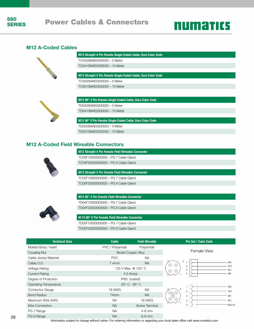
580SERIES Power Cables & Connectors
5
1
4
2
3
1
2
3
4
BN
WH
BU
BK
BN
WH
BK
BU
GN/YE
1
2
4
3
5
12
43
Female View
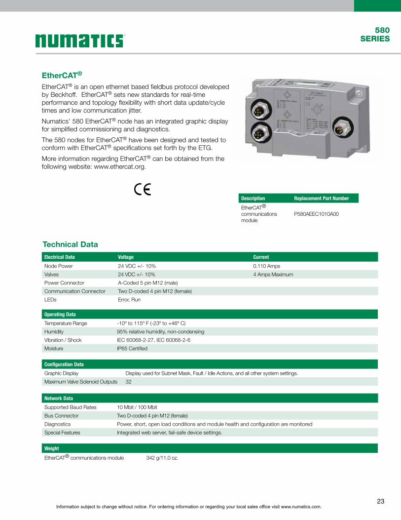
Technical Data Cable Field Wireable Pin Out / Color Code
Molded Body / Insert PVC / Polyamide Polyamide
Coupling Nut Nickel Copper Alloy
Cable Jacket Material PVC NA
Cable O.D. 7.4mm NA
Voltage Rating 125 V Max. @ 105° C
Current Rating 4.0 Amps
Degree of Protection IP65 (mated)
Operating Temperature -25° C - 85° C
Conductor Gauge 18 AWG NA
Bend Radius 74mm NA
Maximum Wire AWG NA 18 AWG
Wire Connection NA Screw Terminal
PG 7 Range NA 4-6 mm
PG 9 Range NA 6-8 mm
M12 A-Coded Field Wireable Connectors
M 12 90° 5 Pin Female Field Wireable Connector
TD05F10000000000 – PG 7 Cable Gland
TD05F20000000000 – PG 9 Cable Gland
M12 Straight 5 Pin Female Field Wireable Connector
TC05F10000000000 – PG 7 Cable Gland
TC05F20000000000 – PG 9 Cable Gland
M12 90° 4 Pin Female Field Wireable Connector
TD04F10000000000 – PG 7 Cable Gland
TD04F20000000000 – PG 9 Cable Gland
M12 Straight 4 Pin Female Field Wireable Connector
TC04F10000000000 – PG 7 Cable Gland
TC04F20000000000 – PG 9 Cable Gland
M12 90° 5 Pin Female Single Ended Cable, Euro Color Code
TD0505MAE0000000 – 5 Meter
TD0510MAE0000000 – 10 Meter
M12 90° 4 Pin Female Single Ended Cable, Euro Color Code
TD0405MAE0000000 – 5 Meter
TD0410MAE0000000 – 10 Meter
M12 Straight 5 Pin Female Single Ended Cable, Euro Color Code
TC0505MAE0000000 – 5 Meter
TC0510MAE0000000 – 10 Meter
M12 A-Coded CablesM12 Straight 4 Pin Female Single Ended Cable, Euro Color Code
TC0405MAE0000000 – 5 Meter
TC0410MAE0000000 – 10 Meter

Information subject to change without notice. For ordering information or regarding your local sales office visit www.numatics.com.29
580SERIES
DeviceNet™ Communication Cables & Connectors
1
2
3
4
Pin 1=ShieldPin 2= V+Pin 3= V-Pin 4= CAN_HPin 5= CAN_L
35
4
2 1
Technical Data Cable M12 Field Wireable "T" Pin Out / Color Code
Molded Body / Insert PVC / PolyamideNickel Plated Zinc /
TPUTPU / TPU GF
Coupling Nut Nickel Plated Brass Nickel Plated Brass Nickel Plated Zinc
Cable Jacket Material PVC NA NA
Cable O.D. 7 mm 4.0 to 8 mm NA
Voltage Rating 300 Volts 60 Volts 60 Volts
Current Rating 4.0 Amps 4.0 Amps 4.0 Amps
Degree of Protection IP65 (mated) IP 65 (mated) IP 65 (mated)
Operating Tempera-ture
-40° C - 80° C -40° C - 85° C -25° C - 90° C
Conductor Gauge 24 AWG (power & data) 26-20 AWG NA
Minimum Bend Radius
74 mm NA NA
Wire Connection NA Spring Cage NA
Female View
M12 A-Coded Field Wireable Connectors
M12 A-Coded Cables
M12 Straight 5 Pin Male & Female Field Wireable Connector – Spring Cage
TA05F2000000071V – PG 9 Cable Gland – Spring Cage Male
TC05F2000000071V – PG 9 Cable Gland – Spring Cage Female
M12 90° 5 Pin Male & Female Single Ended Cable - Shielded
TB0505MGD0000000 – 5 Meter – MALE
TB0510MGD0000000 – 10 Meter – MALE
TD0505MGD0000000 – 5 Meter - FEMALE
TD0510MGD0000000 – 10 Meter - FEMALE
3 Way M12 “T”
TC0500000TT05000 – 12mm
Terminating Resistor - Male
TA05TR0000000000 – 12mm
M12 90° 5 Pin Male & Female Field Wireable Connector – Spring Cage
TB05F2000000071V – PG 9 Cable Gland – Spring Cage Male
TD05F2000000071V – PG 9 Cable Gland – Spring Cage Female
M12 Straight 5 Pin Female Single Ended Cable - Shielded
TA0505MGD0000000 – 5 Meter – MALE
TA0510MGD0000000 – 10 Meter – MALE
TC0505MGD0000000 – 5 Meter - FEMALE
TC0510MGD0000000 – 10 Meter - FEMALE

Information subject to change without notice. For ordering information or regarding your local sales office visit www.numatics.com.30
580SERIES
EtherNet/IP™ CommunicationCables & Connectors
1
2
3
4
WH/OG
OG
WH/GN
GN
34
21
M12 Straight 4 Pin Male D-Coded to RJ45 Female Socket Convertor
QA04D2MK0VC04000 – 0.2 Meter
Male View
M12 D-Coded Field Wireable Connectors
M12 D-Coded Cables
Technical Data Cable M12 Field Wireable Pin Out / Color Code
Molded Body / Insert PUR / Polyamide Nickel Plated Zinc / PA 66
Coupling Nut Nickel Plated Brass Nickel Plated Brass
Cable Jacket Material PUR NA
Cable O.D. 5.6 mm 4.0 to 8 mm
Voltage Rating (Nominal) 300 Volts 60 Volts
Current Rating 2.0 Amps 1.75 Amps
Degree of Protection IP65 (mated) IP 65 (mated)
Operating Temperature -40° C - 75° C -40° C - 85° C
Conductor Gauge 24 AWG IDC 26-22 AWG
Bend Radius 61mm NA
Wire Connection NA IDC
M12 Straight 4 Pin Male D-Coded Field Wireable Connector w/IDC
QA04F2000000071N – PG 9 Cable Gland – IDC
M12 90° 4 Pin Male D-Coded Field Wireable Connector w/IDC
QB04F2000000071N – PG 9 Cable Gland – IDC
M12 Straight 4 Pin Male D-Coded to Male RJ45 Cable
QA0405MK0VA04000 – 5 Meter
QA0410MK0VA04000 – 10 Meter
M12 90° 4 Pin Male D-Coded Single Ended Cable
QB0405MK00000000 – 5 Meter
QB0410MK00000000 – 10 Meter
M12 Straight 4 Pin Male D-Coded Double Ended Cable
QA0405MK0QA04000 – 5 Meter
QA0410MK0QA04000 – 10 Meter
M12 Straight 4 Pin Male D-Coded Single Ended Cable
QA0405MK00000000 – 5 Meter
QA0410MK00000000 – 10 Meter

Information subject to change without notice. For ordering information or regarding your local sales office visit www.numatics.com.31
580SERIES
PROFINET Communication Cables & Connectors
1
2
3
4
YE
WH
OG
BU
34
21
Male View
M12 D-Coded Field Wireable Connectors
M12 D-Coded Cables
Technical Data Cable M12 Field Wireable Pin Out / Color Code
Molded Body / Insert PUR / PUR or PE Nickel Plated Zinc / PA 66
Coupling NutNickel Plated Zinc
and BrassNickel Plated Brass
Cable Jacket Material PVC NA
Cable O.D. 6.5mm / 7.4mm 4.0 to 8.0 mm
Voltage Rating (Nominal) 42 Volts 60 Volts
Current Rating 1.5 Amps 1.75 Amps
Degree of Protection IP65 (mated) IP 65 (mated)
Operating Temperature -25° C - 60° -40° C - 85° C
Conductor Gauge 24 & 22 AWG 26-22 AWG
Bend Radius 19.5 mm NA
Wire Connection NA IDC
M12 Straight 4 Pin Male D-Coded to RJ45 Female Socket Convertor
QA04D2MK0VC04000 – 0.2 Meter
M12 Straight 4 Pin Male D-Coded to Male RJ45 Cable
QA0405MR0VA04000 – 5 Meter
QA0410MR0VA04000 – 10 Meter
M12 Straight 4 Pin Male D-Coded Field Wireable Connector w/IDC
QA04F200R000071N – PG 9 Cable Gland – IDC
M12 90° 4 Pin Male D-Coded Single Ended Cable
QB0405MR00000000 – 5 Meter
QB0410MR00000000 – 10 Meter
M12 Straight 4 Pin Male D-Coded Double Ended Cable
QA0405MR0QA04000 – 5 Meter
QA0410MR0QA04000 – 10 Meter
M12 90° 4 Pin Male D-Coded Field Wireable Connector w/IDC
QB04F200R000071N – PG 9 Cable Gland – IDC
M12 Straight 4 Pin Male D-Coded Single Ended Cable
QA0405MR00000000 – 5 Meter
QA0410MR00000000 – 10 Meter

Information subject to change without notice. For ordering information or regarding your local sales office visit www.numatics.com.32
580SERIES
PROFIBUS DP Communication Cables & Connectors
1
2
3
4
5
GN
RD
34
5
21
M12 Bus “T”
RA050000PRT05000
M12 Straight 5 Pin Terminating Resistor
RA05TR0000000000 – MALE
M12 90° 5 Pin Male & Female Single Ended Cable
RB0505MHP0000000 – 5 Meter – MALE
RB0510MHP0000000 – 10 Meter – MALE
RD0505MHP0000000 – 5 Meter – FEMALE
RD0510MHP0000000 – 10 Meter – FEMALE
M12 Straight 5 Pin Male – to – Female Double Ended Cables
RC0505MHPRA05000 – 5 Meter
RC0510MHPRA05000 – 10 Meter
Male View
M12 B-Coded (Reverse Key) Field Wireable Connectors
M12 B-Coded (Reverse Key) Cables
Technical Data Cable Field Wireable "T" Pin Out / Color Code
Molded Body PUR Nickel Plated Zinc / Brass Aluminum
Insert Polyamide TPU/PVC Nylon
Coupling NutNickel Plated
BrassNickel Plated Brass / Stainless Steel
Nickel Plated Brass
Cable Jacket Material PVC NA NA
Cable O.D. 8.5 mm 4.0 to 8.0 mm / 3.0 to 6.5 mm NA
Voltage Rating 300 Volts 60 Volts 250 Volts
Current Rating 4.0 Amps 4.0 Amps 4.0 Amps
Degree of Protection IP65 (mated) IP 65 (mated) IP 65 (mated)
Operating Tempera-ture
-40° C - 80° C -40° C - 85° C -40° C - 80° C
Conductor Gauge 22 AWG 26-20 AWG / 24-18 AWG NA
Minimum Bend Radius
74 mm NA NA
Wire Connection NA IDC / Screw Terminal NA
M12 Straight 5 Pin Male & Female Field Wireable Connectors
RA05F200P0000000 – PG7 Cable Gland – MALE
RC05F200P0000000 – PG7 Cable Gland – FEMALE
M12 90° 5 Pin Male & Female Field Wireable Connectors, w/IDC
RB05F200P000071V – PG9 Cable Gland – IDC MALE
RD05F200P000071V – PG9 Cable Gland – IDC FEMALE
M12 Straight 5 Pin Male & Female Single Ended Cables
RA0505MHP0000000 – 5 Meter – MALE
RA0510MHP0000000 – 10 Meter – MALE
RC0505MHP0000000 – 5 Meter – FEMALE
RC0510MHP0000000 – 10 Meter – FEMALE

Information subject to change without notice. For ordering information or regarding your local sales office visit www.numatics.com.33
580SERIES
EtherCAT® Communication Cables & Connectors
1
2
3
4
YE
WH
OG
BU
34
21
M12 Straight 4 Pin Male D-Coded to RJ45 Female Socket Convertor
QA04D2MK0VC04000 – 0.2 Meter
Male View
M12 D-Coded Field Wireable Connectors
M12 D-Coded Cables
Technical Data Cable M12 Field Wireable Pin Out / Color Code
Molded Body / Insert PVC / PE Nickel Plated Zinc / PA 66
Coupling Nut Nickel Plated Zinc Nickel Plated Brass
Cable Jacket Material PUR NA
Cable O.D. 6.5 mm 4.0 to 8.0 mm
Voltage Rating (Nominal) 300 Volts 60 Volts
Current Rating 2.0 Amps 1.75 Amps
Degree of Protection IP65 (mated) IP 65 (mated)
Operating Temperature -5° C - 50° C -40° C - 85° C
Conductor Gauge 22 AWG 26-22 AWG
Bend Radius 46 mm NA
Wire Connection NA IDC
M12 Straight 4 Pin Male D-Coded to Male RJ45 Cable
QA0405MT0VA04000 – 5 Meter
QA0410MT0VA04000 – 10 Meter
M12 Straight 4 Pin Male D-Coded Field Wireable Connector w/IDC
QA04F200R000071N – PG 9 Cable Gland – IDC
M12 90° 4 Pin Male D-Coded Single Ended Cable
QB0405MT00000000 – 5 Meter
QB0410MT00000000 – 10 Meter
M12 Straight 4 Pin Male D-Coded Double Ended Cable
QA0405MT0QA04000 – 5 Meter
QA0410MT0QA04000 – 10 Meter
M12 90° 4 Pin Male D-Coded Field Wireable Connector w/IDC
QB04F200R000071N – PG 9 Cable Gland – IDC
M12 Straight 4 Pin Male D-Coded Single Ended Cable
QA0405MT00000000 – 5 Meter
QA0410MT00000000 – 10 Meter