Embed Size (px)
Citation preview

Wollondilly Shire Council C/- NSW Public Works
Geotechnical investigation and concept design
Broughton Pass Flood Damage Wilton Road, Appin, NSW
31 August 2016
DRAFT REPORT FOR R
EVIEW
This report has been produced by Coffey Geotechnics Pty Ltd for Wollondilly Shire Council;any person or organisation reading this report cannot reproduce, rely on or use any information in the report without written
approval from Coffey Geotechnics and a signed reliance deed poll. Any questions about this report are to be directed toWollondilly Shire Council

Quality information
Revision history
Revision Description Date Author Reviewer Signatory
Rev0 Original 31/08/2016 Michael Biabani, Peter Hitchcock
Jon Thompson Jon Thompson
Distribution
Report Status No. of copies Format Distributed to Date
Final 1 PDF Nicole Bailey- NSW Public Works 31/08/2016
DRAFT REPORT FOR R
EVIEW
This report has been produced by Coffey Geotechnics Pty Ltd for Wollondilly Shire Council; any person or organisation reading this report cannot reproduce, rely on or use any information in the report without written
approval from Coffey Geotechnics and a signed reliance deed poll. Any questions about this report are to be directed to Wollondilly Shire Council

Table of contents
1. Introduction .................................................................................................................................. 1
2. Background ................................................................................................................................. 1
3. Objective ...................................................................................................................................... 3
4. Scope of work and methodology ................................................................................................. 3
5. Results of investigation ............................................................................................................... 4
5.1. Planning, management, site safety and fieldwork procedures ......................................... 4
5.2. Site geology....................................................................................................................... 6
5.3. Site surface observations .................................................................................................. 6
5.4. Subsurface conditions ..................................................................................................... 11
5.5. Laboratory test results ..................................................................................................... 12
5.6. Geophysical assessment ................................................................................................ 13
6. Structural remediation options- concept design ........................................................................ 15
6.1. Option 1: Permanent Approach Bridge ........................................................................... 16
6.2. Option 2: Repair damaged embankment and construct new retaining wall ................... 17
6.3. Option 3: Full replacement of approach embankment to western bridge abutment ....... 17
6.4. Preferred Option .............................................................................................................. 18
7. Geotechnical recommendations ................................................................................................ 18
7.1. Earthworks ...................................................................................................................... 18
7.1.1. Bridge extension footings ................................................................................... 19
8. Limitations ................................................................................................................................. 20
Important information about your Coffey Report
Tables
Table 1: Summary of subsurface conditions- Boreholes CBH01 and CBH02
Table 2: Summary of general subsurface conditions, boreholes CBH01 and CBH02
Table 3: Bored pile design parameters DRAFT R
EPORT FOR REVIE
W
This report has been produced by Coffey Geotechnics Pty Ltd for Wollondilly Shire Council; any person or organisation reading this report cannot reproduce, rely on or use any information in the report without written
approval from Coffey Geotechnics and a signed reliance deed poll. Any questions about this report are to be directed to Wollondilly Shire Council

Figures
Figure 1: Site locality
Figure 2: Approximate borehole locations
Figure 3: Geophysics site plan
Figure 4: Subs profiles - Line 1 & line 4
Figure 5: Subs profiles - Line 2 & line 3
Appendices
Appendix A - Borehole Logs, Photos and Explanatory Notes
DRAFT REPORT FOR R
EVIEW
This report has been produced by Coffey Geotechnics Pty Ltd for Wollondilly Shire Council;any person or organisation reading this report cannot reproduce, rely on or use any information in the report without written
approval from Coffey Geotechnics and a signed reliance deed poll. Any questions about this report are to be directed toWollondilly Shire Council

1. Introduction
This report presents the findings and recommendations of a geotechnical investigation and concept design carried out by Coffey Geotechnics Pty Ltd (Coffey) for NSW Public Works, on behalf of the Principal - Wollondilly Shire Council (WSC), in relation to the rectification of a failed section of Wilton Road at the western approach to Broughton Pass Bridge over the Cataract River between Wilton and Appin, NSW.
The failure of the road occurred where a high stone block retaining wall at the approach to the western abutment of the bridge collapsed during the intense rainfall events and flooding that occurred between 3 and 5 June 2016. The road formation collapsed within the west bound lane and exposed part of the western abutment of the bridge. The east bound lane is supported by a similar stone block wall and remained largely intact following the failure. However access to the bridge was prevented due to the risk of further collapse and encroachment of the failure into this lane.
Preliminary recommendations were implemented to reduce the likelihood of further movement occurring which included closure of the bridge to traffic, diversion of surface water away from the failure and covering the exposed surface of the failed slope with a heavy gauge plastic sheet to limit further ingress of water. Coffey has also provided advice on a temporary single lane bridge to span the failed section of road.
This report provides an assessment of the subsurface conditions at the site, concept structural design for proposed remedial options and recommendations on geotechnical parameters for pile design.
2. Background
Based on provided document by WSC, Broughton Pass Bridge was originally constructed over a century ago as a two span timber structure with stone abutments and central pier. It was replaced by a two span concrete girder structure constructed about 70 years ago with the stone abutments and piers remaining. The abutments are constructed near the toe of steeply sloping terrain adjacent to the banks of the Cataract River. The steep slopes form the sideslopes of Broughton Pass and are underlain by sandstone which outcrops as cliffs on some parts of the slopes.
Coffey has previously carried out a preliminary geotechnical assessment of the southern stone block retaining wall adjacent to the western bridge abutment to assess the condition and stability of the retaining wall, as documented in our report GEOTWOLL03302AA-AB, dated 27/11/2011. A significant bulge in the stone wall on the southern side of the road at the approach to the western bridge abutment was observed at the time of our 2011inspection. . The bulge was in the south wall was estimated to be about 200-250 mm out of inferred original alignment. Photos 1 and 2 show view of the western abutment before failure (September 2011). Some settlement on the road at the western approach to the bridge was observed and reported during our 2011 inspection.
DRAFT REPORT FOR R
EVIEW
This report has been produced by Coffey Geotechnics Pty Ltd for Wollondilly Shire Council; any person or organisation reading this report cannot reproduce, rely on or use any information in the report without written
approval from Coffey Geotechnics and a signed reliance deed poll. Any questions about this report are to be directed toWollondilly Shire Council

Photo 1: View of the western bridge abutment and dry packed stone wall supporting the road formation on the southern side of the road approach to the bridge. Note bulging of the retaining wall (September 2011).
Photo 2: View looking east down slope to the river showing bulge in stone retaining supporting fill at the approach to the western bridge abutment. Note bulge in wall (September 2011).
DRAFT REPORT FOR R
EVIEW
This report has been produced by Coffey Geotechnics Pty Ltd for Wollondilly Shire Council; any person or organisation reading this report cannot reproduce, rely on or use any information in the report without written
approval from Coffey Geotechnics and a signed reliance deed poll. Any questions about this report are to be directed to Wollondilly Shire Council

3. Objective
The objectives of this current geotechnical investigation as outlined in the brief were to provide advice on the following:
A general description of the site geology;
Subsurface conditions likely to underlie the existing ground and determine changes to thebedrock level;
Field assessment of the slopes affecting the abutment as well as any existing drainagestructures;
Earthworks including ease of excavation, engineered placement of fill;
A geotechnical works for the site to enable detailed design and construction of the works;
Providing options for the reconstruction of the abutment to allow the road to be reopened tothe public;
Concept design to retaining wall options and/or possible suspended road over the failedsection; and
All solutions (involving remedial earthworks) shall include the installation of subsurfacedrainage for the backfill against the existing 1938 abutment, and shall be suitable to allowinstallation of W beam barriers and terminals.
4. Scope of work and methodology
To address the above objectives, the following scope of work was completed:
Desk study comprising review of previous available reports and geological, soil landscape maps;
Site reconnaissance and observations of relevant geotechnical/geological site features around thefailed wall and road;
Site observations and initial site meeting with WSC engineers to confirm test locations
Subsurface investigation, comprising: Drilling of two (2) boreholes, CBH01 and CBH02 to maximum depths of 17.5m and 23.3m
respectively within or adjacent to the road on the western approach to the bridge abutment.Boreholes were drilled using a track mounted drilling rig. Boreholes were commenced initiallyusing auger with tungsten carbide (TC) drilling bit, then the boreholes were extended to thetarget depth by diamond coring methods;
PVC casing was installed in Borehole CBH01 to support the walls of the borehole wherepassing through fill, natural soils or weak rock. A pvc casing was installed in Borehole CBH02for the full depth of the borehole to allow the geophysics to be carried out;
A geotechnical engineer was onsite full time during fieldwork to direct the drilling operator,collect soil/rock samples, log the subsurface conditions, and reinstate boreholes;
Geophysical assessment comprising surface to borehole seismic (SUBS) tomography;
Laboratory testing of rock samples representative of the subsurface conditions encountered at thesample depth including; Point Load Index testing,15 tests;
Meeting with WSC engineers to discuss site history and available drawings for the bridge androad formation/retaining walls. Also discussion of possible options for the rectification of the road;and
Preparation of a report on the results of the investigation and provision of concept design forremediation options.
DRAFT REPORT FOR R
EVIEW
This report has been produced by Coffey Geotechnics Pty Ltd for Wollondilly Shire Council; any person or organisation reading this report cannot reproduce, rely on or use any information in the report without written
approval from Coffey Geotechnics and a signed reliance deed poll. Any questions about this report are to be directed to Wollondilly Shire Council

5. Results of investigation
5.1. Planning, management, site safety and fieldwork procedures
Safety is our priority: we believe the safe delivery of a project is a measure of quality. Coffey is committed to providing a safe and healthy working environment for all our employees and subcontractors. Accordingly a site specific safety plan was prepared to assess the potential safety risks associated with carrying out the fieldwork. This plan included (but was not limited to) an emergency contact list, an assessment of the risks associated with the fieldwork prior to going to site, re-assessment at the site, personal protective equipment requirements, emergency response, Environmental Safe Work Method Statements (ESWMS), etc. The key risks our staff and subcontractors were exposed to during the works were buried services such as power. Fieldwork included:
Initial site observations by a principal geotechnical engineer and site meeting with WSC andPublic Works engineers;
Checking of test locations for underground services by a Telstra approved service locator;
Two boreholes within the alignment of the proposed road and retaining wall in vicinity of thebridge abutment using a track mounted. In view of the presence of coarse rock backfill materialexposed behind the failed retaining wall, specialist drilling techniques were employed comprisinga combination of rotary auger drilling and ‘SIM-CAS’ drilling methods. The SIM-CAS method is acasing advancer system, which provided casing of the walls of the borehole as the hole wasadvanced, preventing collapse while air hammering through the rocky fill;
Once the weathered rock surface was encountered beneath the fill and natural soils, theboreholes were continued by diamond coring to maximum depths of 17.5m and 23.3m inboreholes CBH01 and CBH02 respectively;
Surface to borehole seismic (SUBS) tomography, a non-destructive geophysical technique, toassist in characterisation of subsurface materials;
The site locality plan and borehole locations are shown in Figures 1 and 2 respectively. CBH01 was plugged through the upper 1m. CBH02 was cased and grouted and is outside of the carriageway. As the road had been closed there was no traffic passing the site during the drilling and geophysics work.
All borehole drilling works were undertaken in the full time presence of a Coffey geotechnical engineer, who was responsible for the management of site safety/contractors, locating / logging / sampling of all boreholes and site reinstatement on completion. In view of the rocky fill conditions encountered in Borehole CBH01, no Standard Penetration Tests (SPTs) were carried out. Photo 3 shows borehole CBH01, positioned within the road close to the western edge of the failure.
To undertake surface-to-borehole seismic tomography, a 60mm diameter pvc casing with end cap was installed in CBH02 to support the walls of the borehole where passing through fill, natural soils or weak rock, and also to allow the hole to be filled with water for the geophysical testing The borehole was grouted around the annulus of the pvc pipe to a depth of 23.2m below ground level to allow the temporary vertical installation of the hydrophone array. Photo 4 shows Borehole CBH02 with pvc casing installed and grouted.
DRAFT REPORT FOR R
EVIEW
This report has been produced by Coffey Geotechnics Pty Ltd for Wollondilly Shire Council; any person or organisation reading this report cannot reproduce, rely on or use any information in the report without written
approval from Coffey Geotechnics and a signed reliance deed poll. Any questions about this report are to be directed to Wollondilly Shire Council

Photo 3: Location of borehole CBH01 near the western edge of the failure. Note safety barriers and sandbags were placed along the top of the failed section of road to secure the work area and control runoff into the failure zone. The barriers were also used to secure the plastic sheeting that was spread over the surface of the failure
areas to limit water ingress.
Photo 4: PVC casing installed in CBH02 with grouting of annulus in progress. CBH02 was positioned behind the guard rail adjacent to the rock cutting.
DRAFT REPORT FOR R
EVIEW
This report has been produced by Coffey Geotechnics Pty Ltd for Wollondilly Shire Council;any person or organisation reading this report cannot reproduce, rely on or use any information in the report without written
approval from Coffey Geotechnics and a signed reliance deed poll. Any questions about this report are to be directed toWollondilly Shire Council

Although drilling locations were located near the failure zone and close to steep slopes or cliffs and in close proximity to the Cataract River, the drilling work was performed with no safety or environmental issues occurring during the fieldwork.
Easting and northing co-ordinates and surface levels of the borehole locations were recorded by survey carried out by WSC. The engineering logs of the boreholes core photographs with explanatory notes are provided in Appendix A.
5.2. Site geology
Reference to the Wollongong 1:250,000 Geological Series Sheet SI 56.9, published by the Department of Mines 1966 second edition, indicates that the site is located within the Hawkesbury Sandstone group, which consists of the quartz sandstone, with some shale.
Bedrock outcrops in the vicinity of the investigation indicate distinctly bedded slightly weathered sandstone with some thin extremely to highly weathered interbedded layers.
5.3. Site surface observations
Broughton Pass is located on Wilton Road between Wilton and Appin, NSW. Where the bridge at Broughton Pass crosses the Cataract River, a section of the road on the approach to the western abutment collapsed where a stone block retaining wall failed during the storms and severe rainfall and during the period 3 to 5 June, 2016. River levels also rose during this period and during our site visit of 6 June, significant flows and turbulence was noted in the vicinity of the bridge.
On the upstream and downstream sides of the existing abutment, cobbles and boulders of varying size ranging mainly from about 200 to 500mm maximum dimension were observed in the exposed fill. The slide debris comprising rocky fill continued down the slope past the bridge abutment and into the river.
Photos 5 to 7 show the failure of the retaining wall and fill collapse below the road at the western abutment of the Broughton Pass Bridge observed on 6 and 13 June 2016.
There were some signs of detached rock on the steep slopes above the site (Photo 8). There is some risk of landslide activity occurring over the sandstone cliffs and steep slopes above the site.
DRAFT REPORT FOR R
EVIEW
This report has been produced by Coffey Geotechnics Pty Ltd for Wollondilly Shire Council; any person or organisation reading this report cannot reproduce, rely on or use any information in the report without written
approval from Coffey Geotechnics and a signed reliance deed poll. Any questions about this report are to be directed toWollondilly Shire Council
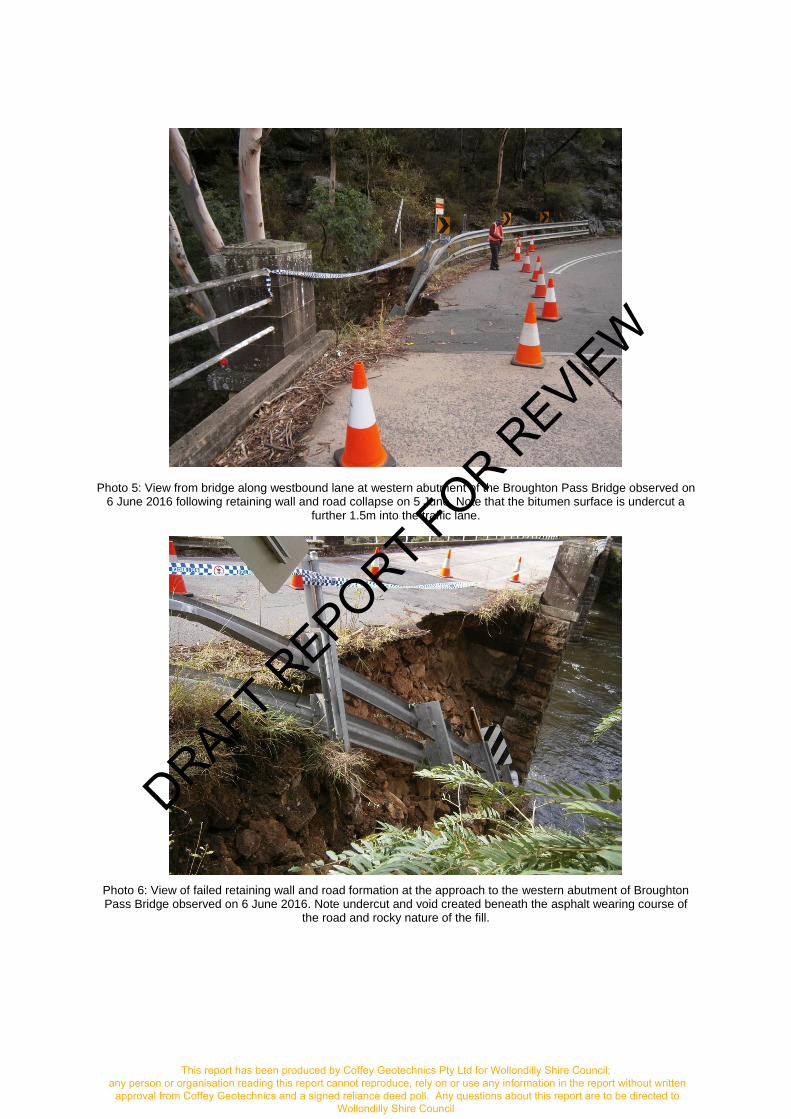
Photo 5: View from bridge along westbound lane at western abutment of the Broughton Pass Bridge observed on 6 June 2016 following retaining wall and road collapse on 5 June. Note that the bitumen surface is undercut a
further 1.5m into the traffic lane.
Photo 6: View of failed retaining wall and road formation at the approach to the western abutment of Broughton Pass Bridge observed on 6 June 2016. Note undercut and void created beneath the asphalt wearing course of
the road and rocky nature of the fill.
DRAFT REPORT FOR R
EVIEW
This report has been produced by Coffey Geotechnics Pty Ltd for Wollondilly Shire Council;any person or organisation reading this report cannot reproduce, rely on or use any information in the report without written
approval from Coffey Geotechnics and a signed reliance deed poll. Any questions about this report are to be directed toWollondilly Shire Council

Photo 7: View of western approach to Broughton Pass Bridge over Cataract River (13 July 2016) and position of failure zone relative to the bridge as indicated by water filled barriers.
Photo 8: Close up view of open joints in rock near borehole CBH02. Note large rock mass partly detached from rock face and tree root on top of sandstone adjacent to the drainage path. This type of rock structure may be
expected in the upper few metres of the rock profile indicating a deep socket for piles may be required to ensure penetration of this zone.
DRAFT REPORT FOR R
EVIEW
This report has been produced by Coffey Geotechnics Pty Ltd for Wollondilly Shire Council;any person or organisation reading this report cannot reproduce, rely on or use any information in the report without written
approval from Coffey Geotechnics and a signed reliance deed poll. Any questions about this report are to be directed toWollondilly Shire Council

Photo 9: High near vertical sandstone rock cutting on high side of road near the western bridge abutment andCBH02) adjacent to the drainage path on the high side edge of the road. Note very weak thin layers of
extremely to highly weathered sandstone were observed to be interbedded with stronger rock.
The stone block wall on the northern side of the road opposite the failure is of similar height to the southern side. Some displacement of blocks in the upper part of the wall has occurred with opening of gaps between blocks also occurring, however no significant bulging was observed in this wall. (Photo 10).The opening or displacement of blocks may be attributed to some root action from the vegetation in this area and some movement of the wall due to traffic loading and vibration.
The remaining road pavement between the failure and the northern stone block wall is shown in Photo 11. The high rock cutting above the road is shown in Photos 9 and 12 with seepages evident over the rock face.
DRAFT REPORT FOR R
EVIEW
This report has been produced by Coffey Geotechnics Pty Ltd for Wollondilly Shire Council; any person or organisation reading this report cannot reproduce, rely on or use any information in the report without written
approval from Coffey Geotechnics and a signed reliance deed poll. Any questions about this report are to be directed to Wollondilly Shire Council

Photo 10: View (west to east) of northern stone block retaining wall adjacent to western abutment of bridge at Broughton Pass. Note gaps between blocks and some blocks displaced laterally in upper part of wall
Photo 11: View (east to west) of western abutment of the western approach to Broughton Pass Bridge. Note some minor settlement of the road and opening of cracks in surface (27 July 2016) compared to initial failure (5
June 2016). Geophysics lines area shown in green on pavement adjacent to bridge abutment.
DRAFT REPORT FOR R
EVIEW
This report has been produced by Coffey Geotechnics Pty Ltd for Wollondilly Shire Council;any person or organisation reading this report cannot reproduce, rely on or use any information in the report without written
approval from Coffey Geotechnics and a signed reliance deed poll. Any questions about this report are to be directed toWollondilly Shire Council

Photo 12: View of Wilton road near western approach to abutment of Broughton Pass Bridge. Note surface water drains down the uphill edge of the road via kerb and gutter directing runoff to a discharge point at the base of the cliff directly upslope of the failed section of road. Note that small amounts of debris can block the surface drains and divert runoff back onto the road. The runoff can subsequently flow to other discharge points along the edges
of the road closer to the bridge.
5.4. Subsurface conditions
The general subsurface conditions encountered in boreholes CBH01 to CBH02 are summarised in Table 1. Engineering logs are presented in Appendix A. The following observations were made when reviewing the engineering logs:
In Borehole CBH01, fill material comprising cobbles and boulders and some voids occurred to adepth of about 0.8m to1.0m below ground surface;
The weathered rock consisted of sandstone, initially highly or moderately weathered near thesurface, then moderately to slightly weathered with some highly weathered zones. Core loss wasrecorded in boreholes CBH01 (6.83 to 7.09m) and CBH02 (15.68 to 16.0 m) which is likely to beassociated with a layer of extremely weathered material or clay seam;
Groundwater inflows may be expected through weak or fractured zones within the rock and belowriver level.
Table 1: Summary of subsurface conditions- Boreholes CBH01 and CBH02
Unit Unit Description Approximate depth range to top of unit in boreholes (m)
Thickness range of unit (m)
Pavement/Roadbase Gravelly SAND, fine to coarse sand, pale brown, sub-medium to coarse sub-angular gravel, fine to coarse cemented gravel
Surface 0.0 to 0.5(borehole CBH01 only)
DRAFT REPORT FOR R
EVIEW
This report has been produced by Coffey Geotechnics Pty Ltd for Wollondilly Shire Council; any person or organisation reading this report cannot reproduce, rely on or use any information in the report without written
approval from Coffey Geotechnics and a signed reliance deed poll. Any questions about this report are to be directed to Wollondilly Shire Council

Unit Unit Description Approximate depth range to top of unit in boreholes (m)
Thickness range of unit (m)
Fill Sandstone cobbles and boulders: medium to coarse grained sandstone fragments, brown orange brown, some gravel, sand and silt as infill between larger rocks, approximate 200mm to 500mm in size, occasional voids. Concrete occurred at the surface in Borehole CBH02 as part of drainage path.
0.1 to 0.5 0.6(CBH02) to 6.0(CBH01)
Extremely to highly weathered Sandstone
Gravelly SAND: fine to coarse grained, brown, fine to coarse angular to sub-angular gravel, trace of organics, trace of low plasticity clay.
0.6 to 0.8 (CBH02) 0.30 to 0.40
Highly weathered Sandstone
SANDSTONE: fine to coarse grained, brown orange mottled, covered as Gravelly SAND.
0.9 to 1.0 (CBH02) 0.1 to 0.2
Moderately to slightly weathered Sandstone
SANDSTONE: fine to coarse grained, pale grey mottled, pale brown, trace of fine to medium gravel inclusions. Some highly weathered zones. Mainly medium and high strength with some low strength.
6.0 (CBH01) and 1.15 (CBH02)
Unconfirmed – extends to at least 17.5m (CBH01) and 23.32m (CBH02) depth.
The depth ranges at which these materials were encountered are detailed in Table 2:
Table 2: Summary of general subsurface conditions, boreholes CBH01 and CBH02
Test site Depth range of material (m)
Pavement/Road base or concrete
Fill EW to HW sandstone
HW sandstone
MW/SW Sandstone
CBH01 0.0-0.5 0.5-6.0 - - 6.0-17.5*
CBH02 0.0-0.7 - 0.7-1.0 1.0-1.15 1.15-23.32*
Notes to Table 1: * = End of Borehole
5.5. Laboratory test results
Laboratory test reports on the rock core testing are presented in Appendix A. The point load index test results ranged from about 0.19 to 1.6 MPa on rock core samples retrieved from the boreholes. The point load index test provides an index of strength and not a direct strength value. Correlations between Point Load Index and unconfined compressive strength (UCS) are derived per rock type statistically using a number of test results. Sandstone rocks typically have a UCS to point load ratio in the range 10 to 20 for rocks with point load index greater than 1.0MPa.
The visual assessment of the rock strength during the borehole drilling indicates rock with greater than 70% RQD (Rock Quality Designation). This would suggest that using a ratio of around 15 for estimate of UCS from point load index would be appropriate, resulting in an estimated range of UCS from 2.9MPa to 24MPa. This would indicate the rock core samples tested are typically medium to high
DRAFT REPORT FOR R
EVIEW
This report has been produced by Coffey Geotechnics Pty Ltd for Wollondilly Shire Council; any person or organisation reading this report cannot reproduce, rely on or use any information in the report without written
approval from Coffey Geotechnics and a signed reliance deed poll. Any questions about this report are to be directed to Wollondilly Shire Council

strength, with some low strength seams evident. Some higher strength rock may occur in the lower part of CBH02.
5.6. Geophysical assessment
Geophysical testing using Surface to borehole seismic (SUBS) tomography, a seismic P-wave / compressional wave method, was completed in accordance with industry practice and Coffey’s Quality System (ISO 9001 accredited) and Operational Health and Safety Plans.
The seismic testing collected compressional (P) wave velocity information at CBH2 which was cased with PVC and grouted to the surrounding material. Forty eight (48) seismic hydrophone receivers, spaced by 0.5m, were deployed down CBH2 and seismic coupling was achieved by filling the PVC casing with water. The first receiver was positioned at 22.5m depth below the ground surface.
Seismic energy was generated at the ground surface by summed impacts of a sledge hammer against a metal plate and was repeated at 3m intervals along the survey lines. The survey was completed along Lines 1 to 3 which extended from CBH2 towards to the bridge abutment and Line 4 which extended along the northern road alignment away from the bridge location. CBH2 was selected to be Ch.0m along each survey line.
The deployment of the seismic receivers is shown in Photo 12 and the generation of the seismic signal is shown in Photo 13. The SUBS line locations and Coffey borehole locations are shown in the site plan provided in Figure 3.
Photo 13: View of PVC casing installed in CBH02, with seismic hydrophone receivers placed in borehole
DRAFT REPORT FOR R
EVIEW
This report has been produced by Coffey Geotechnics Pty Ltd for Wollondilly Shire Council; any person or organisation reading this report cannot reproduce, rely on or use any information in the report without written
approval from Coffey Geotechnics and a signed reliance deed poll. Any questions about this report are to be directed to Wollondilly Shire Council
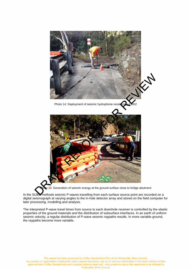
Photo 14: Deployment of seismic hydrophone receivers in CBH2
Photo 15: Generation of seismic energy at the ground surface close to bridge abutment
In the SUBS methods seismic P-waves travelling from each surface source point are recorded on a digital seismograph at varying angles to the in-hole detector array and stored on the field computer for later processing, modelling and analysis.
The interpreted P-wave travel times from source to each downhole receiver is controlled by the elastic properties of the ground materials and the distribution of subsurface interfaces. In an earth of uniform seismic velocity, a regular distribution of P-wave seismic raypaths results. In more variable ground, the raypaths become more variable.
DRAFT REPORT FOR R
EVIEW
This report has been produced by Coffey Geotechnics Pty Ltd for Wollondilly Shire Council; any person or organisation reading this report cannot reproduce, rely on or use any information in the report without written
approval from Coffey Geotechnics and a signed reliance deed poll. Any questions about this report are to be directed to Wollondilly Shire Council

Should the subsurface conditions or elastic properties vary laterally around the borehole within the zone of investigation, for example as a result of weaker voided ground or highly fractured rock, then the travel times to each receiver will vary. Similarly, any condition which weakens rock will normally lead to a scattering of the seismic wave and a delay in the travel time that will additionally modify the subsurface seismic velocity distribution.
The P-wave information was picked interactively using Rayfract © and inverted using a combination of Rayfract and GEOTOMCG software to produce a subsurface P-wave velocity distribution, or seismic tomographic image, beneath each survey line. The tomographic images show the areas covered by the raypaths generated at the surface, which generally lie in a path between the source and receiver position. Tomographic imaging to the base of the bridge abutment was partially covered by raypaths achieved from the source positions completed onsite. The SUBS profiles along Lines 1 to 4 are presented in Figures 4 and 5 with simplified borehole logs for CBH1 and CBH2.
SUBS Lines 1 to 4 present velocities that vary with depth and laterally from CBH2 with a range from 600 to 3000m/s. Lower velocities are observed along Line 1 to 3, which is consistent with the looser, weaker material as a result of the failed retaining structure and fractured rock. P-wave velocity information along SUBS Line 1 to 3 are presented in Figures 4 and 5 and represent velocities adjacent to the failed retaining wall up to 9m from the borehole at the ground surface and are truncated to the depth of the hole and represent the limits of the seismic raypaths recorded onsite. Subsequent to the failure of the southern retaining wall, the elastic properties of the fill and rock have been reduced, which in turn reduce the P-wave seismic velocities. Additionally, closeness of the source location to the borehole increases the steepness of the rays and the likelihood that the seismic velocities will be lowered as a result of passing through the shallow fill material behind the bridge abutment.
Borehole CBH2 encountered rock at approximately 1m depth, however a lower velocity zone is observed adjacent to CBH2 that extends to approximately 15 m depth alongside of the hole. This effect is often observed where the drilling process has had a weakening effect on the ground material around the hole. Along SUBS Line 1 the P-wave velocity structure is greater than 1000m/s and generally closer to 1600m/s. The velocity structure is generally uniform and at velocities greater than 1600 m/s which represents rock strength material.
The correlation of the borehole logs and the seismic information along SUBS Lines 1 and 4, presented in Figure 4, shows the1000m/s level correspond to the level of rock presented in CBH1 and 2. Figure 4 shows the interpreted rock level which has been extended to CBH1, beyond the limit ofthe SUBS investigation. While the velocities in this area may be artificially lowered by the shallow fills, lower rock velocities represent weaker rock material with decreased fracture spacing.
The velocities near 1000m/s on SUBS Line 2 to 3 present poor correlation with this velocity level on SUBS Line 1 and with the rock levels provided in CBH1 and CBH2. Velocities less than 1000m/s are observed on SUBS 2 and 3 due to the reduction in modulus of material as a result of the failed retaining wall.
6. Structural remediation options- concept design
DRAFT REPORT FOR R
EVIEW
This report has been produced by Coffey Geotechnics Pty Ltd for Wollondilly Shire Council; any person or organisation reading this report cannot reproduce, rely on or use any information in the report without written
approval from Coffey Geotechnics and a signed reliance deed poll. Any questions about this report are to be directed to Wollondilly Shire Council

8. Limitations
The findings of this report are the result of specific methodologies used in accordance with normal practices and standards. To the best of our knowledge, they represent a reasonable interpretation of the general condition of the site at the time of the assessment. Should any ground conditions become evident during construction that vary from those described in this report, Coffey should be contacted to seek further advice.
DRAFT REPORT FOR R
EVIEW
This report has been produced by Coffey Geotechnics Pty Ltd for Wollondilly Shire Council;any person or organisation reading this report cannot reproduce, rely on or use any information in the report without written
approval from Coffey Geotechnics and a signed reliance deed poll. Any questions about this report are to be directed toWollondilly Shire Council

Important information about your Coffey Report As a client of Coffey you should know that site subsurface conditions cause more construction problems than any other factor. These notes have been prepared by Coffey to help you interpret and understand the limitations of your report.
Coffey Geotechnics Pty Ltd ABN 93 056 929 483 Page 1 of 2 Issued: 11 August 2016
Your report is based on project specific criteria
Your report has been developed on the basis of your unique project specific requirements as understood by Coffey and applies only to the site investigated. Project criteria typically include the general nature of the project; its size and configuration; the location of any structures on the site; other site improvements; the presence of underground utilities; and the additional risk imposed by scope-of-service limitations imposed by the client. Your report should not be used if there are any changes to the project without first asking Coffey to assess how factors that changed subsequent to the date of the report affect the report's recommendations. Coffey cannot accept responsibility for problems that may occur due to changed factors if they are not consulted.
Subsurface conditions can change
Subsurface conditions are created by natural processes and the activity of man. For example, water levels can vary with time, fill may be placed on a site and pollutants may migrate with time. Because a report is based on conditions which existed at the time of subsurface exploration, decisions should not be based on a report whose adequacy may have been affected by time. Consult Coffey to be advised how time may have impacted on the project.
Interpretation of factual data
Site assessment identifies actual subsurface conditions only at those points where samples are taken and when they are taken. Data derived from literature and external data source review, sampling and subsequent laboratory testing are interpreted by geologists, engineers or scientists to provide an opinion about overall site conditions, their likely impact on the proposed development and recommended actions. Actual conditions may differ from those inferred to exist, because no professional, no matter how qualified, can reveal what is hidden by earth, rock and time. The actual interface between materials may be far more gradual or abrupt than assumed based on the facts obtained. Nothing can be done to change the actual site conditions which exist, but steps can be taken to reduce the impact of unexpected conditions. For this reason, owners should retain the services of Coffey through the development stage, to identify variances, conduct additional tests if required, and recommend solutions to problems encountered on site.
Your report will only give preliminary recommendations
Your report is based on the assumption that the site conditions as revealed through selective point sampling are indicative of actual conditions throughout an area. This assumption cannot be substantiated until project implementation has commenced and therefore your report recommendations can only be regarded as preliminary. Only Coffey, who prepared the report, is fully familiar with the background information needed to assess whether or not the report's recommendations are valid and whether or not changes should be considered as the project develops. If another party undertakes the implementation of the recommendations of this report there is a risk that the report will be misinterpreted and Coffey cannot be held responsible for such misinterpretation.
Your report is prepared for specific purposes and persons
To avoid misuse of the information contained in your report it is recommended that you confer with Coffey before passing your report on to another party who may not be familiar with the background and the purpose of the report. Your report should not be applied to any project other than that originally specified at the time the report was issued.
Interpretation by other design professionals
Costly problems can occur when other design professionals develop their plans based on misinterpretations of a report. To help avoid misinterpretations, retain Coffey to work with other project design professionals who are affected by the report. Have Coffey explain the report implications to design professionals affected by them and then review plans and specifications produced to see how they incorporate the report findings.
DRAFT REPORT FOR R
EVIEW
This report has been produced by Coffey Geotechnics Pty Ltd for Wollondilly Shire Council; any person or organisation reading this report cannot reproduce, rely on or use any information in the report without written
approval from Coffey Geotechnics and a signed reliance deed poll. Any questions about this report are to be directed to Wollondilly Shire Council

Coffey Geotechnics Pty Ltd ABN 93 056 929 483 Page 2 of 2 Issued: 11 August 2016
Data should not be separated from the report*
The report as a whole presents the findings of the site assessment and the report should not be copied in part or altered in any way. Logs, figures, drawings, etc. are customarily included in our reports and are developed by scientists, engineers or geologists based on their interpretation of field logs (assembled by field personnel) and laboratory evaluation of field samples. These logs etc. should not under any circumstances be redrawn for inclusion in other documents or separated from the report in any way.
Geoenvironmental concerns are not at issue
Your report is not likely to relate any findings, conclusions, or recommendations about the potential for hazardous materials existing at the site unless specifically required to do so by the client. Specialist equipment, techniques, and personnel are used to perform a geoenvironmental assessment. Contamination can create major health, safety and environmental risks. If you have no information about the potential for your site to be contaminated or create an environmental hazard, you are advised to contact Coffey for information relating to geoenvironmental issues.
Rely on Coffey for additional assistance
Coffey is familiar with a variety of techniques and approaches that can be used to help reduce risks for all parties to a project, from design to construction. It is common that not all approaches will be necessarily dealt with in your site assessment report due to concepts proposed at that time. As the project progresses through design towards construction, speak with Coffey to develop alternative approaches to problems that may be of genuine benefit both in time and cost.
Responsibility
Reporting relies on interpretation of factual information based on judgement and opinion and has a level of uncertainty attached to it, which is far less exact than the design disciplines. This has often resulted in claims being lodged against consultants, which are unfounded. To help prevent this problem, a number of clauses have been developed for use in contracts, reports and other documents. Responsibility clauses do not transfer appropriate liabilities from Coffey to other parties but are included to identify where Coffey's responsibilities begin and end. Their use is intended to help all parties involved to recognise their individual responsibilities. Read all documents from Coffey closely and do not hesitate to ask any questions you may have.
* For further information on this aspect reference should be
made to "Guidelines for the Provision of Geotechnical information in Construction Contracts" published by the Institution of Engineers Australia, National headquarters, Canberra, 1987.
DRAFT REPORT FOR R
EVIEW
This report has been produced by Coffey Geotechnics Pty Ltd for Wollondilly Shire Council; any person or organisation reading this report cannot reproduce, rely on or use any information in the report without written
approval from Coffey Geotechnics and a signed reliance deed poll. Any questions about this report are to be directed to Wollondilly Shire Council

Figures
DRAFT REPORT FOR R
EVIEW
This report has been produced by Coffey Geotechnics Pty Ltd for Wollondilly Shire Council; any person or organisation reading this report cannot reproduce, rely on or use any information in the report without written
approval from Coffey Geotechnics and a signed reliance deed poll. Any questions about this report are to be directed to Wollondilly Shire Council

drawn MB
client: Wollondilly Shire Council C/- NSW Public Works
approved JPT project:
Broughton Pass Flood Damage Wilton Road, Appin, NSW
date 15/08/2016
scale N.T.S. title: Site locality (Ref: Google Earth Pro, Map Data: © 2015
DigitalGlobe)
original size
A4 project no: GEOTWOLL03302AC-AA figure no: 1
DRAFT REPORT FOR R
EVIEW
This report has been produced by Coffey Geotechnics Pty Ltd for Wollondilly Shire Council; any person or organisation reading this report cannot reproduce, rely on or use any information in the report without written
approval from Coffey Geotechnics and a signed reliance deed poll. Any questions about this report are to be directed to Wollondilly Shire Council

drawn MB
client: Wollondilly Shire Council C/- NSW Public Works
approved JPT project:
Broughton Pass Flood Damage Wilton Road, Appin, NSW
date 15/08/2016
scale N.T.S. title: Borehole locations. (Ref: Google Earth Pro, Map Data: ©
2015 DigitalGlobe)
original size
A4 project no: GEOTWOLL03302AC-AA figure no: 2
CBH01
CBH02
DRAFT REPORT FOR R
EVIEW
This report has been produced by Coffey Geotechnics Pty Ltd for Wollondilly Shire Council; any person or organisation reading this report cannot reproduce, rely on or use any information in the report without written
approval from Coffey Geotechnics and a signed reliance deed poll. Any questions about this report are to be directed to Wollondilly Shire Council
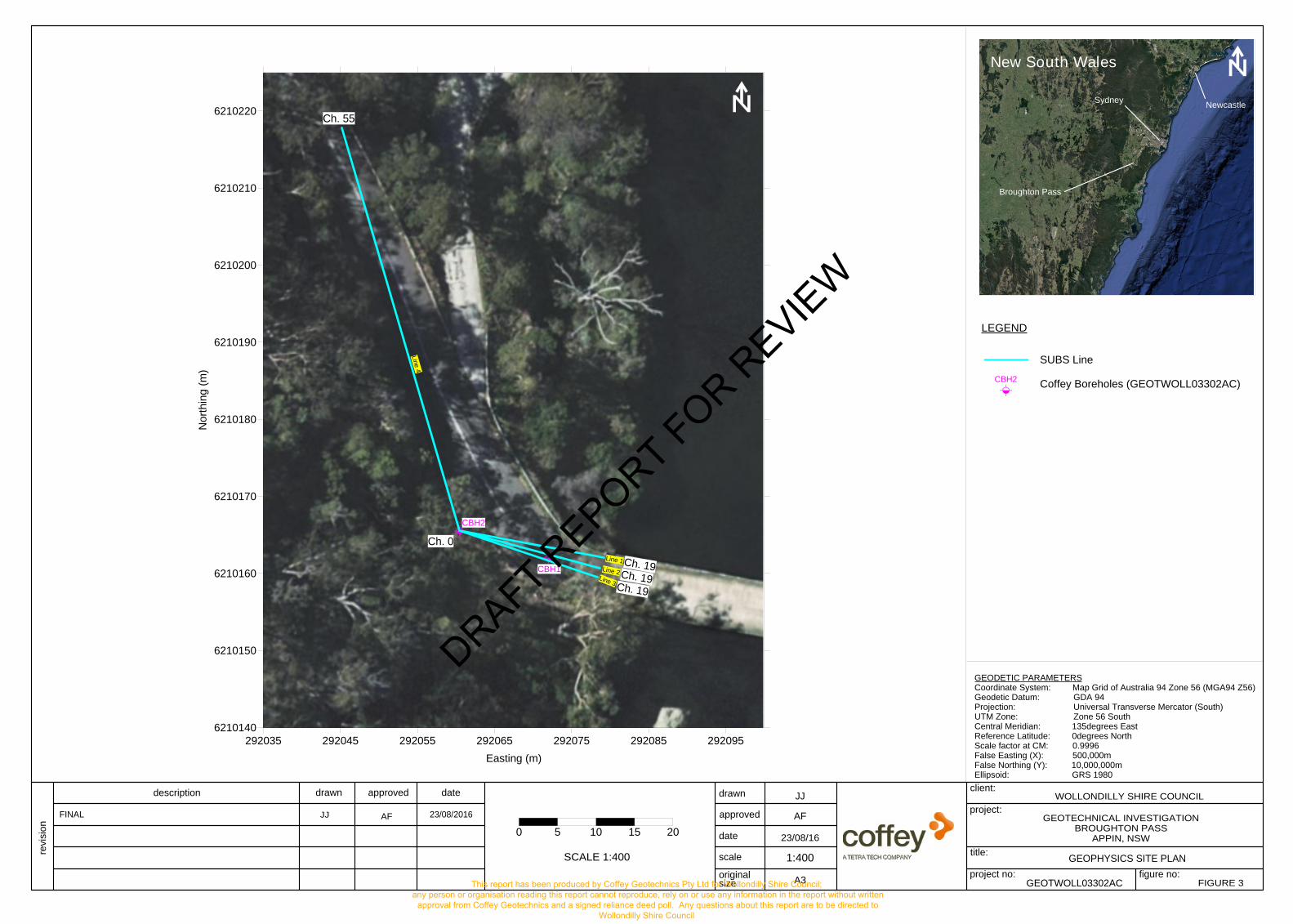
figure no:project no:
drawn
approved
date
scale
Scale (metres)
revi
sion
description drawn approved date
project:
title:
client:
originalsize
Scale (metres)
WOLLONDILLY SHIRE COUNCIL
GEOPHYSICS SITE PLAN
GEOTWOLL03302AC
JJ
23/08/16
A3 FIGURE 3
FINAL JJ 23/08/2016 AF
LEGEND
GEODETIC PARAMETERSCoordinate System: Map Grid of Australia 94 Zone 56 (MGA94 Z56)Geodetic Datum: GDA 94Projection: Universal Transverse Mercator (South)UTM Zone: Zone 56 SouthCentral Meridian: 135degrees EastReference Latitude: 0degrees NorthScale factor at CM: 0.9996False Easting (X): 500,000mFalse Northing (Y): 10,000,000mEllipsoid: GRS 1980
SUBS Line
Coffey Boreholes (GEOTWOLL03302AC)
GEOTECHNICAL INVESTIGATIONBROUGHTON PASS
APPIN, NSW
SCALE 1:400 1:400
CBH2
CBH1
292035 292045 292055 292065 292075 292085 292095Easting (m)
6210140
6210150
6210160
6210170
6210180
6210190
6210200
6210210
6210220
Nor
thin
g (m
)
New South Wales
Broughton Pass
Sydney Newcastle
Ch. 55
Ch. 0
Line 2
Line 4
0 5 10 15 20
Line 3
Line 1
CBH2
Ch. 19Ch. 19
Ch. 19
AF
DRAFT REPORT FOR R
EVIEW
This report has been produced by Coffey Geotechnics Pty Ltd for Wollondilly Shire Council; any person or organisation reading this report cannot reproduce, rely on or use any information in the report without written
approval from Coffey Geotechnics and a signed reliance deed poll. Any questions about this report are to be directed to Wollondilly Shire Council

figure no:project no:
drawn
approved
date
scale
Scale (metres)
revi
sion
description drawn approved date
project:
title:
client:
originalsize
Scale (metres)
WOLLONDILLY SHIRE COUNCIL
SUBS PROFILES - LINE 1 & LINE 4
GEOTWOLL03302AC
TW
23/08/16
A3 FIGURE 4
TW 23/08/2016 AF
LEGEND
SUBS Line
Coffey Boreholes (GEOTWOLL03302AC)
Interpreted Rock Level
GEOTECHNICAL INVESTIGATIONBROUGHTON PASS
APPIN, NSW
SCALE 1:200 1:200
CBH2
CBH1
Ch. 55
Ch. 0
Ch. 19
Line 1
Line 4
ASPHALT
CALCRETE
GRAVELLYSAND
SAND
SANDSTONE
SILTSTONE
NO CORE
GRAVELLYSAND
COFFEY BOREHOLE LEGEND
FINAL
800
800
800
800
1000
1000
1000
1000
1200
1200 1400
1600
1600
1600
1800
1800
1800
1800
1800
1800
1800
2000
2000
2000
2000
2000
2000
22002400
26002800
-15 -10 -5 0 5 10 15 20 25 30 35CHAINAGE (m)
-20
-15
-10
-5
0
LEV
EL
(m)
0 2.5 5 7.5 10
CBH2
600 800 1000 1200 1400 1600 1800 2000 2200 2400 2600 2800 3000
P-Wave Velocity (m/s)
LINE4LINE1
VD
D to VD
HW
MWXWMW
MW
HW
MW
EL VL L M H VH EH
-0.03
-0.1
-0.3
-1 -3 -10
(0 m)
VDVDD to VDH
MW
HW
HW
SW
MW
SW - FR
EL VL L M H VH EH
-0.03
-0.1
-0.3
-1 -3 -10
(0 m)
CBH1 CBH2
AF
DRAFT REPORT FOR R
EVIEW
This report has been produced by Coffey Geotechnics Pty Ltd for Wollondilly Shire Council; any person or organisation reading this report cannot reproduce, rely on or use any information in the report without written
approval from Coffey Geotechnics and a signed reliance deed poll. Any questions about this report are to be directed to Wollondilly Shire Council

figure no:project no:
drawn
approved
date
scale
Scale (metres)
revi
sion
description drawn approved date
project:
title:
client:
originalsize
Scale (metres)
WOLLONDILLY SHIRE COUNCIL
SUBS PROFILES - LINE 2 & 3
GEOTWOLL03302AC
TW
23/08/16
A3 FIGURE 5
FINAL TW 23/08/2016 AF GEOTECHNICAL INVESTIGATIONBROUGHTON PASS
APPIN, NSW
SCALE 1:200 1:250
800
02.557.51012.515CHAINAGE (m)
SUBS Line 1
-20
-15
-10
-5
0
DE
PTH
(m)
0 2.5 5 7.5 10
800800
1000
1000
1000
1000
1200
1200 1400
-15 -10 -5 0CHAINAGE (m)
SUBS Line 2
-20
-15
-10
-5
0
LEV
EL
(m)
-10 -5 0
-20
-15
-10
-5
0
VD
D to VD
HW
MWXWMW
MW
HW
MW
EL VL L M H VH EH
-0.03
-0.1
-0.3
-1 -3 -10
(0 m)
VDVDD to VDH
MW
HW
HW
SW
MW
SW - FR
EL VL L M H VH EH
-0.03
-0.1
-0.3
-1 -3 -10
(0 m)
800
800
1000
1000
1200
1400
1800
-15 -10 -5 0CHAINAGE (m)
SUBS Line 3
-20
-15
-10
-5
0
LEVE
L (m
)
LEGENDSUBS Presented
SUBS Line
Coffey Boreholes (GEOTWOLL03302AC)
ASPHALT
CALCRETE
GRAVELLYSAND
SAND
SANDSTONE
SILTSTONE
NO CORE
GRAVELLYSAND
COFFEY BOREHOLE LEGEND
CBH2
CBH2
CBH1
Ch. 55
Ch. 0
Ch. 19Line 1
Line 4
Line 2Line 3Ch. 19Ch. 19
VD
D to VD
HW
MWXWMW
MW
HW
MW
EL VL L M H VH EH
-0.03
-0.1
-0.3
-1 -3 -10
(0 m)
VDVDD to VDH
MW
HW
HW
SW
MW
SW - FR
EL VL L M H VH EH
-0.03
-0.1
-0.3
-1 -3 -10
(0 m)
600 1000 1400 1800 2200 2600 3000
P-Wave Velocity (m/s)
CBH1 CBH2 CBH1 CBH2
AF
DRAFT REPORT FOR R
EVIEW
This report has been produced by Coffey Geotechnics Pty Ltd for Wollondilly Shire Council; any person or organisation reading this report cannot reproduce, rely on or use any information in the report without written
approval from Coffey Geotechnics and a signed reliance deed poll. Any questions about this report are to be directed to Wollondilly Shire Council

Appendix A - Borehole Logs, Photos and Explanatory Notes
DRAFT REPORT FOR R
EVIEW
This report has been produced by Coffey Geotechnics Pty Ltd for Wollondilly Shire Council; any person or organisation reading this report cannot reproduce, rely on or use any information in the report without written
approval from Coffey Geotechnics and a signed reliance deed poll. Any questions about this report are to be directed to Wollondilly Shire Council

Soil Description Explanation Sheet; Issue Date: 15/08/16; UNCONTROLLED WHEN PRINTED Page 1 of 2
Soil Description Explanation Sheet (1 of 2)
DEFINITION: In engineering terms soil includes every type of uncemented or partially cemented inorganic or organic material found in the ground. In practice, if the material can be remoulded or disintegrated by hand in its field condition or in water it is described as a soil. Other materials are described using rock description terms.
CLASSIFICATION SYMBOL & SOIL NAME
Soils are described in accordance with the Unified Soil Classification (UCS) as shown in the table on Sheet 2.
PARTICLE SIZE DESCRIPTIVE TERMS
NAME SUBDIVISION SIZE
Boulders
Cobbles
>200 mm
63 mm to 200 mm
Gravel coarse
medium
fine
20 mm to 63 mm
6 mm to 20 mm
2.36 mm to 6 mm
Sand coarse
medium
fine
600 μm to 2.36 mm
200 μm to 600 μm
75 μm to 200 μm
MOISTURE CONDITION
Dry Looks and feels dry. Cohesive and cemented soils are hard, friable or powdery. Uncemented granular soils run freely through hands.
Moist Soil feels cool and darkened in colour. Cohesive soils can be moulded. Granular soils tend to cohere.
Wet As for moist but with free water forming on hands when handled.
CONSISTENCY OF COHESIVE SOILS
TERM UNDRAINED STRENGTH
su (kPa) FIELD GUIDE
Very Soft <12 A finger can be pushed well into the soil with little effort.
Soft 12 – 25 A finger can be pushed into the soil to about 25mm depth.
Firm 25 – 50 The soil can be indented about 5mm with the thumb, but not penetrated.
Stiff 50 – 100 The surface of the soil can be indented with the thumb, but not penetrated.
Very Stiff 100 – 200 The surface of the soil can be marked, but not indented with thumb pressure.
Hard >200 The surface of the soil can be marked only with the thumbnail.
Friable – Crumbles or powders when scraped by thumbnail.
DENSITY OF GRANULAR SOILS
TERM DENSITY INDEX (%)
Very loose Less than 15
Loose 15 – 35
Medium Dense 35 – 65
Dense 65 – 85
Very Dense Greater than 85
MINOR COMPONENTS
TERM ASSESSMENT GUIDE PROPORTION OF MINOR
COMPONENT IN:
Trace of Presence just detectable by feel or eye, but soil properties little or no different to general properties of primary component.
Coarse grained soils: <5%
Fine grained soils: <15%
With some
Presence easily detected by feel or eye, soil properties little different to general properties of primary component.
Coarse grained soils: 5 - 12%
Fine grained soils: 15 - 30%
SOIL STRUCTURE
ZONING CEMENTING
Layers Continuous across exposure or sample.
Weakly cemented
Easily broken up by hand in air or water.
Lenses Discontinuous shape.
Moderately cemented
Effort is required to break up the soil by hand in air or water.
Pockets Irregular inclusions of different material.
GEOLOGICAL ORIGIN WEATHERED IN PLACE SOILS
Extremely weathered material
Structure and fabric of parent rock visible.
Residual soil Structure and fabric of parent rock not visible.
TRANSPORTED SOILS
Aeolian soil Deposited by wind.
Alluvial soil Deposited by streams and rivers.
Colluvial soil Deposited on slopes (transported downslope by gravity).
Fill Man-made deposit. Fill may be significantly more variable between tested locations than naturally occurring soils.
Lacustrine soil Deposited by lakes.
Marine soil Deposited in ocean basins, bays, beaches and estuaries.
DRAFT REPORT FOR R
EVIEW
This report has been produced by Coffey Geotechnics Pty Ltd for Wollondilly Shire Council; any person or organisation reading this report cannot reproduce, rely on or use any information in the report without written
approval from Coffey Geotechnics and a signed reliance deed poll. Any questions about this report are to be directed to Wollondilly Shire Council

Soil Description Explanation Sheet; Issue Date: 15/08/16; UNCONTROLLED WHEN PRINTED Page 2 of 2
Soil Description Explanation Sheet (2 of 2)
SOIL CLASSIFICATION INCLUDING IDENTIFICATION AND DESCRIPTION
FIELD IDENTIFICATION PROCEDURES USC (Excluding particles larger than 60 mm and basing fractions on estimated mass) USC
PRIMARY NAME
CO
AR
SE
GR
AII
NE
D S
OIL
S M
ore
than
50%
of
mat
eria
ls
less
than
63
mm
is la
rger
than
0.0
75 m
m
(A 0
.075
mm
par
ticle
is a
bout
the
sm
alle
st p
artic
le v
isib
le t
o th
e na
ked
eye)
GR
AV
ELS
M
ore
than
hal
f of
coa
rse
frac
tion
is la
rger
tha
n 2.
36
mm
CLE
AN
G
RA
VE
LS
(Litt
le o
r no
fin
es)
Wide range in grain size and substantial amounts of all intermediate particle sizes
GW GRAVEL
Predominantly one size or a range of sizes with more intermediate sizes missing.
GP GRAVEL
GR
AV
ELS
W
ITH
F
INE
S
App
reci
able
am
ount
of
fines
) Non-plastic fines (for identification procedures see ML below) GM SILTY GRAVEL
Plastic fines (for identification procedures see CL below) GC CLAYEY GRAVEL
SA
ND
S
Mor
e th
an h
alf
of c
oars
e fr
actio
n is
sm
alle
r th
an 2
.36
mm
CLE
AN
S
AN
DS
(L
ittle
or
no
fines
)
Wide range in grain sizes and substantial amounts of all intermediate sizes
SW SAND
Predominantly one size or a range of sizes with some intermediate sizes missing.
SP SAND
SA
ND
S
WIT
H
FIN
ES
(A
ppre
ciab
le
amou
nt o
f fin
es)
Non-plastic fines (for identification procedures see ML below). SM SILTY SAND
Plastic fines (for identification procedures see CL below). SC CLAYEY SAND
FIN
E G
RA
INE
D S
OIL
S M
ore
than
50
% o
f m
ater
ial l
ess
than
63
mm
is
smal
ler
than
0.0
75 m
m
IDENTIFICATION PROCEDURES ON FRACTIONS <0.2 mm
SIL
TS
&
CLA
YS
Li
quid
lim
it le
ss th
an 5
0
DRY STRENGTH DILATANCY TOUGHNESS
None to Low Quick to slow None ML SILT
Medium to High None Medium CL CLAY
Low to medium Slow to very slow Low CL ORGANIC SILT
SIL
TS
&
CLA
YS
Li
quid
lim
it gr
eate
r th
an 5
0
Low to medium Slow to very slow Low to medium MH SILT
High None High CH CLAY
Medium to High None Low to medium OH ORGANIC
CLAY
HIGHLY ORGANIC SOILS Readily identified by colour, odour, spongy feel and frequently by fibrous texture. PT PEAT
Low plasticity – Liquid Limit wL less than 35%. Medium plasticity – wL between 35% and 50%. High plasticity – wL greater than 50%.
COMMON DEFECTS IN SOIL
TERM DEFINITION DIAGRAM TERM DEFINITION DIAGRAM
PARTING A surface or crack across which the soil has little or no tensile strength. Parallel or sub parallel to layering (eg bedding). May be open or closed.
SOFTENED ZONE
A zone in clayey soil, usually adjacent to a defect in which the soil has a higher moisture content than elsewhere.
JOINT A surface or crack across which the soil has little or no tensile strength but which is not parallel or sub parallel to layering. May be open or closed. The term 'fissure' may be used for irregular joints <0.2 m in length
TUBE Tubular cavity. May occur singly or as one of a large number of separate or inter-connected tubes. Walls often coated with clay or strengthened by denser packing of grains. May contain organic matter.
SHEARED ZONE
Zone in clayey soil with roughly parallel near planar, curved or undulating boundaries containing closely spaced, smooth or slickensided, curved intersecting joints which divide the mass into lenticular or wedge shaped blocks.
TUBE CAST Roughly cylindrical elongated body of soil different from the soil mass in which it occurs. In some cases the soil which makes up the tube cast is cemented.
SHEARED SURFACE
A near planar curved or undulating, smooth,polished or slickensided surface in clayeysoil. The polished or slickensided surfaceindicates that movement (in many cases very little) has occurred along the defect.
INFILLED SEAM
Sheet or wall like body of soil substance or mass with roughly planar to irregular near parallel boundaries which cuts through a soil mass. Formed by infilling of open joints.
DRAFT REPORT FOR R
EVIEW
This report has been produced by Coffey Geotechnics Pty Ltd for Wollondilly Shire Council; any person or organisation reading this report cannot reproduce, rely on or use any information in the report without written
approval from Coffey Geotechnics and a signed reliance deed poll. Any questions about this report are to be directed to Wollondilly Shire Council

Rock Description Explanation Sheet - Australia; Issue Date: 15/08/16; UNCONTROLLED WHEN PRINTED Page 1 of 2
Rock Description Explanation Sheet (1 of 2)
The descriptive terms used by Coffey are given below. They are broadly consistent with Australian Standard AS1726-1993. DEFINITIONS: Rock substance, defect and mass are defined as follows:
Rock Substance In engineering terms rock substance is any naturally occurring aggregate of minerals and organic material which cannot be disintegrated or remoulded by hand in air or water. Other material is described using soil descriptive terms. Effectively homogenous material, may be isotropic or anisotropic.
Defect Discontinuity or break in the continuity of a substance or substances. Mass Any body of material which is not effectively homogeneous. It can consist of two or more substances without defects, or one
or more substances with one or more defects.
SUBSTANCE DESCRIPTIVE TERMS:
ROCK NAME Simple rock names are used rather than precise geological classification.
PARTICLE SIZE Grain size terms for sandstone are:
Coarse grained Mainly 0.6mm to 2mm
Medium grained Mainly 0.2mm to 0.6mm
Fine grained Mainly 0.06mm (just visible) to 0.2mm
FABRIC Terms for layering of penetrative fabric (eg. bedding, cleavage etc. ) are:
Massive No layering or penetrative fabric.
Indistinct Layering or fabric just visible. Little effect on properties.
Distinct Layering or fabric is easily visible. Rock breaks more easily parallel to layering of fabric.
CLASSIFICATION OF WEATHERING PRODUCTS
Term Abbreviation Definition
Residual Soil
RS Soil derived from the weathering of rock; the mass structure and substance fabric are no longer evident; there is a large change in volume but the soil has not been significantly transported.
Extremely Weathered Material
XW Material is weathered to such an extent that it has soilproperties, ie, it either disintegrates or can be remoulded in water. Original rock fabric still visible.
Highly Weathered Rock
HW Rock strength is changed by weathering. The whole of the rock substance is discoloured, usually by iron staining or bleaching to the extent that the colour of the original rock is not recognisable. Some minerals are decomposed to clay minerals. Porosity may be increased by leaching or may be decreased due to the deposition of minerals in pores.
Moderately Weathered Rock
MW The whole of the rock substance is discoloured, usually by iron staining or bleaching , to the extent that the colour of the fresh rock is no longer recognisable.
Slightly Weathered Rock
SW Rock substance affected by weathering to the extent that partial staining or partial discolouration of the rock substance (usually by limonite) has taken place. The colour and texture of the fresh rock is recognisable; strength properties are essentially those of the fresh rock substance.
Fresh Rock FR Rock substance unaffected by weathering.
Notes on Weathering: AS1726 suggests the term "Distinctly Weathered" (DW) to cover the range of substance weathering conditions between XW and SW. For projects where it is not practical to delineate between HW and MW or it is judged that there is no advantage in making such a distinction. DW may be used with the definition given in AS1726. Where physical and chemical changes were caused by hot gasses and liquids associated with igneous rocks, the term "altered" may be substituted for "weathering" to give the abbreviations XA, HA, MA, SA and DA.
ROCK SUBSTANCE STRENGTH TERMS
Term Abbre-viation
Point Load Index, Is(50)
(MPa)
Field Guide
Very Low VL Less than 0.1 Material crumbles under firm blows with sharp end of pick; can be peeled with a knife; pieces up to 30mm thick can be broken by finger pressure.
Low L 0.1 to 0.3 Easily scored with a knife; indentations 1mm to 3mm show with firm bows of a pick point; has a dull sound under hammer. Pieces of core 150mm long by 50mm diameter may be broken by hand. Sharp edges of core may be friable and break during handling.
Medium M 0.3 to 1.0 Readily scored with a knife; a piece of core 150mm long by 50mm diameter can be broken by hand with difficulty.
High H 1 to 3 A piece of core 150mm long by 50mm can not be broken by hand but can be broken by a pick with a single firm blow; rock rings under hammer.
Very High VH 3 to 10 Hand specimen breaks after more than one blow of a pick; rock rings under hammer.
Extremely High
EH More than 10 Specimen requires many blows with geological pick to break; rock rings under hammer.
Notes on Rock Substance Strength: In anisotropic rocks the field guide to strength applies to the strength perpendicular to the anisotropy. High strength anisotropic rocks may break readily parallel to the planar anisotropy. The term "extremely low" is not used as a rock substance strength term. While the term is used in AS1726-1993, the field guide therein makes it clear that materials in that strength range are soils in engineering terms. The unconfined compressive strength for isotropic rocks (and anisotropic rocks which fall across the planar anisotropy) is typically 10 to 25 times the point load index Is(50). The ratio may vary for different rock types. Lower strength rocks often have lower ratios than higher strength rocks.
DRAFT REPORT FOR R
EVIEW
This report has been produced by Coffey Geotechnics Pty Ltd for Wollondilly Shire Council; any person or organisation reading this report cannot reproduce, rely on or use any information in the report without written
approval from Coffey Geotechnics and a signed reliance deed poll. Any questions about this report are to be directed to Wollondilly Shire Council

Rock Description Explanation Sheet - Australia; Issue Date: 15/08/16; UNCONTROLLED WHEN PRINTED Page 2 of 2
Rock Description Explanation Sheet (2 of 2)
COMMON DEFECTS IN ROCK MASSES DEFECT SHAPE TERMS
Planar The defect does not vary in orientation
Curved The defect has a gradual change in orientation
Undulating The defect has a wavy surface
Stepped The defect has one or more well defined steps
Irregular The defect has many sharp changes of orientation
Note: The assessment of defect shape is partly influenced by the scale of the observation. ROUGHNESS TERMS
Slickensided Grooved or striated surface, usually polished
Polished Shiny smooth surface
Smooth Smooth to touch. Few or no surface irregularities
Rough Many small surface irregularities (amplitude generally less than 1mm). Feels like fine to coarse sand paper.
Very Rough Many large surface irregularities (amplitude generally more than 1mm). Feels like, or coarser than very coarse sand paper.
COATING TERMS
Clean No visible coating
Stained No visible coating but surfaces are discoloured
Veneer A visible coating of soil or mineral, too thin to measure; may be patchy
Veneer A visible coating up to 1mm thick. Thicker soil material is usually described using appropriate defect terms (eg, infilled seam). Thicker rock strength material is usually described as a vein.
BLOCK SHAPE TERMS
Blocky Approximately equidimensional
Tabular Thickness much less than length or width
Columnar Height much greater than cross section
Term Definition Diagram Map Symbol
Graphic Log(Note 1)
Parting A surface or crack across which the rock has little or no tensile strength. but which is not parallel or sub parallel to layering or planar anisotropy in the rock substance. May be open or closed.
Joint A surface or crack across which the rock has little or no tensile strength. but which is not parallel or sub parallel to layering or planar anisotropy in the rock substance. May be open or closed.
Sheared Zone (Note 3)
Zone of rock substance with roughly parallel near planar, curved or undulating boundaries cut by closely spaced joints, sheared surfaces or other defects. Some of the defects are usually curved and intersect to divide the mass into lenticular or wedge shaped blocks.
Sheared Surface (Note 3)
A near planar, curved or undulating surface which is usually smooth, polished or slickensided.
Crushed Seam (Note 3)
Seam with roughly parallel almost planar boundaries, composed of disoriented, usually angular fragments of the host rock substance which may be more weathered than the host rock. The seam has soil properties
Infilled Seam
Seam of soil substance usually with distinct roughly parallel boundaries formed by the migration of soil into an open cavity or joint, infilled seams less than 1mm thick may be described as veneer or coating on joint surface.
Extremely Weathered Seam
Seam of soil substance, often with gradational boundaries. Formad by weathering of the rock substance in place.
Notes on Defects:
1. Usually borehole logs show the true dip of defects and face sketches and sections the apparent dip.
2. Partings and joints are not usually shown on the graphic log unless considered significant.
3. Sheared zones, sheared surfaces and crushed seams are faults in geological terms.
72
71
0 /
07
-06
DRAFT REPORT FOR R
EVIEW
This report has been produced by Coffey Geotechnics Pty Ltd for Wollondilly Shire Council; any person or organisation reading this report cannot reproduce, rely on or use any information in the report without written
approval from Coffey Geotechnics and a signed reliance deed poll. Any questions about this report are to be directed to Wollondilly Shire Council

AD
/TA
H
CA
SIN
G
ASPHALT.
Gravelly SAND: fine to coarse grained, palebrown, medium to coarse sub-angular gravel.
SANDSTONE COBBLES AND BOULDERS:medium to coarse grained, brown/orange brown,trace of silt and sand.
approximate 100mm to 500mm in size, some voids
Borehole CBH1 continued as cored hole
WEARING COURSE
ROADBASE
FILL
VD
D toVD
D
RL
(m)
138
137
136
135
134
133
drilling information material substance
CBH1
GEOTWOLL03302AC
13 Jul 2016
13 Jul 2016
MB
JPT
Borehole ID.
sheet:
project no.
date started:
date completed:
logged by:
checked by:
client:
principal:
location:
Wollondilly Shire Council C/-NSW Public Works
Wilton Road, Appin, NSW
project: Broughton Pass Flood Damage - Retaining wall failure
Engineering Log - Borehole1 of 3
grap
hic
log
clas
sific
atio
nsy
mbo
l
samples &field tests
wat
er
samples & field tests consistency / relative densitysupportM mudC casing
N nil
classification symbol &soil descriptionbased on Unified
Classification System
water
water outflow
water inflow
penetration
no resistanceranging torefusal
10-Oct-12 waterlevel on date shown
method
1 2 3AH air hammer
ADASHAW
auger drilling*auger screwing*hand augerwashbore
*e.g.BTV
bit shown by suffixAD/Tblank bitTC bitV bit
BDESSU##HPNN*NcVSRHB
bulk disturbed sampledisturbed sampleenvironmental samplesplit spoon sampleundisturbed sample ##mm diameterhand penetrometer (kPa)standard penetration test (SPT)SPT - sample recoveredSPT with solid conevane shear; peak/remouded (kPa)refusalhammer bouncing
VSSFStVStHFbVLLMDDVD
very softsoftfirmstiffvery stiffhardfriablevery looseloosemedium densedensevery dense
met
hod
&su
ppor
t SOIL TYPE: plasticity or particle characteristic,colour, secondary and minor components
material description structure andadditional observations
1 2 3pe
netr
atio
n
dept
h (m
)
1.0
2.0
3.0
4.0
5.0
position: E: 292072; N: 6210162 (Datum Not Specified)
drill model: 3.5T Excavator, Track mounted
angle from horizontal: 90°
casing diameter : HQ
surface elevation: 138.80 m (AHD)
drilling fluid:
cons
iste
ncy
/re
lativ
e de
nsi
ty
moi
stur
eco
nditi
on
CD
F_0
_9_0
6_L
IBR
AR
Y.G
LB r
ev:A
M L
og C
OF
BO
RE
HO
LE: N
ON
CO
RE
D G
EO
TW
OLL
0330
2AC
.GP
J <
<D
raw
ingF
ile>
> 3
1/08
/201
6 13
:11
moistureDMWWpWl
drymoistwetplastic limitliquid limit
(kPa)
100
200
300
400
handpenetro-
meter
DRAFT REPORT FOR R
EVIEW
This report has been produced by Coffey Geotechnics Pty Ltd for Wollondilly Shire Council; any person or organisation reading this report cannot reproduce, rely on or use any information in the report without written
approval from Coffey Geotechnics and a signed reliance deed poll. Any questions about this report are to be directed to Wollondilly Shire Council

NM
LC
MW
HW -MW
MW
XWMW
HW -MW
XW
MW -SW
SANDSTONE: fine to coarse grained, pale greymottled, pale brown, trace of fine to mediumsubangular to angular gravel inclusions. distinctlybedded @ 20 to 30 degrees.
possibly detached from rock mass
NO CORE: 0.26 m
SANDSTONE: fine to coarse grained, pale greymottled, pale brown, trace of fine to mediumsubangular to angular gravel inclusions. distinctlybedded @ 0 to 10 degrees.
colour change to brown mottled brown/ darkbrown/pale grey
start coring at 6.00m
76%
76%
78%
93%
PT, 30°, PL, RO, VN
Drilling Break
PT, 30°, PL, RO, VN
PT, 10°, PL, RO, CO - Sand, x5, 50mm spacing
PT, 10°, PL, RO, CO - Sand
SM, 5°, PL, Sandy clay, 30 mm
SM, 20°, PL, Clay, 30 mm
PT, 20°, PL, RO, VN
JT, 60°, PL, RO, CO - Sand
JT, 45°, PL, RO, VN
PT, 15°, PL, RO, VN, 40 mm
PT, 10°, PL, RO, VN
JT, 15°, PL, RO, CO - Sand, x2, 40mm spacing
SM, 10°, IR, Clayey sand, 30 mm
a=0.70d=0.72
d=0.73a=1.29
d=0.68a=0.67
d=0.19a=0.80
d=0.80a=1.05
RL
(m)
132
131
130
129
128
127
drilling information material substance rock mass defects
(graphic symbols indicate material)
10/10/12, waterlevel on date shown
core run & RQD
barrel withdrawn
25uL
method & support graphic log / core recovery
partial drilling fluid loss
water inflow
water pressure test result(lugeons) for depthinterval shown
RQD = Rock Quality Designation (%)
ASADCBWNMLCNQHQPQSPT
auger screwingauger drillingclaw or blade bitwashboreNMLC core (51.9 mm)wireline core (47.6mm)wireline core (63.5mm)wireline core (85.0mm)standard penetrationtest
AH air hammer
water
complete drilling fluid loss no core recovered
core recovered
grap
hic
log
defectspacing(mm)
30 100
300
1000
3000
met
hod
&su
ppor
t
wea
ther
ing
&al
tera
tionROCK TYPE: grain characterisics,
colour, structure, minor components
material description
core
run
& R
QD
CBH1
GEOTWOLL03302AC
13 Jul 2016
13 Jul 2016
MB
JPT
Borehole ID.
sheet:
project no.
date started:
date completed:
logged by:
checked by:
client:
principal:
location:
Wollondilly Shire Council C/-NSW Public Works
Wilton Road, Appin, NSW
project: Broughton Pass Flood Damage - Retaining wall failure
Engineering Log - Cored Borehole2 of 3
particular general
additional observations anddefect descriptions
(type, inclination, planarity, roughness, coating,thickness, other)
& Is50 = axial;
= diametral
VL
L M H VH
EH
estimatedstrength
dept
h (m
)
6.0
7.0
8.0
9.0
10.0
11.0
position: E: 292072; N: 6210162 (Datum Not Specified)
drill model: 3.5T Excavator, Track mounted vane id.:
angle from horizontal: 90°
casing diameter : HQ
surface elevation: 138.80 m (AHD)
drilling fluid:
SLPOLSOROVR
slickensidedpolishedsmoothroughvery rough
roughness coatingCNSNVNCO
cleanstainveneercoating
planarityPLCUUNSTIR
planarcurvedundulatingsteppedIrregular
weathering & alteration*RSXWHWDWMWSWFR
residual soilextremely weatheredhighly weathereddistinctly weatheredmoderately weatheredslightly weatheredfresh
*W replaced with A for alteration
defect typePTJTSZSSCOCSSM
partingjointshear zoneshear surfacecontactcrushed seamseam
CD
F_0
_9_0
6_L
IBR
AR
Y.G
LB r
ev:A
M L
og C
OF
BO
RE
HO
LE: C
OR
ED
GE
OT
WO
LL03
302
AC
.GP
J <
<D
raw
ingF
ile>
> 3
1/08
/201
6 13
:06
a = axial;d = diametral
samples,field tests& Is(50)(MPa)
strengthVLLMHVHEH
very lowlowmediumhighvery highextremely high
wat
er
DRAFT REPORT FOR R
EVIEW
This report has been produced by Coffey Geotechnics Pty Ltd for Wollondilly Shire Council; any person or organisation reading this report cannot reproduce, rely on or use any information in the report without written
approval from Coffey Geotechnics and a signed reliance deed poll. Any questions about this report are to be directed to Wollondilly Shire Council

NM
LC
MW -SW
MW
MW -SW
SANDSTONE: fine to coarse grained, pale greymottled, pale brown, trace of fine to mediumsubangular to angular gravel inclusions. distinctlybedded @ 0 to 10 degrees. (continued)
thin mudstone LENSE, 20 mm thick
thin mudstone LENSE, 20 mm thick
thin mudstone LENSE, 30 mm thick
Borehole CBH1 terminated at 17.50 mTarget depth
93%
81%
PT, 10°, PL, RO, VN
PT, 15°, PL, RO, SN
PT 0, 10°, PL, RO, VN, x2, 110 mmspacing
SM, 20°, PL, Clayey sand, 20 mm
PT, 10°, PL, RO, VN, x2, 40 mmspacing JT, 10°, PL, RO, VN PT, 10°, PL, RO, VN, 80 mm spacing
PT, 10°, PL, RO, VN, x2, 20 mmspacing JT, 80°, PL, RO, CO - Sandy clay SM, Sandy clay, 20 mm JT, 40°, PL, RO, VN JT, 10°, IR, RO, CO - VN PT, 10°, PL, RO, VN CS 0, 10°, PL, RO, CO - Sand, 5-20mm spacing JT, 15°, IR, RO, CO - Sand JT, 50°, PL, RO, VN, x2, 20 mmspacing PT, 0°, PL, RO, VN, 30 mm
SM, 10°, UN, RO, CO - Sand, 20 mm
JT, 10°, UN, RO, CO - Sand
d=0.34a=0.73
a=0.86d=0.92
RL
(m)
126
125
124
123
122
121
drilling information material substance rock mass defects
(graphic symbols indicate material)
10/10/12, waterlevel on date shown
core run & RQD
barrel withdrawn
25uL
method & support graphic log / core recovery
partial drilling fluid loss
water inflow
water pressure test result(lugeons) for depthinterval shown
RQD = Rock Quality Designation (%)
ASADCBWNMLCNQHQPQSPT
auger screwingauger drillingclaw or blade bitwashboreNMLC core (51.9 mm)wireline core (47.6mm)wireline core (63.5mm)wireline core (85.0mm)standard penetrationtest
AH air hammer
water
complete drilling fluid loss no core recovered
core recovered
grap
hic
log
defectspacing(mm)
30 100
300
1000
3000
met
hod
&su
ppor
t
wea
ther
ing
&al
tera
tionROCK TYPE: grain characterisics,
colour, structure, minor components
material description
core
run
& R
QD
CBH1
GEOTWOLL03302AC
13 Jul 2016
13 Jul 2016
MB
JPT
Borehole ID.
sheet:
project no.
date started:
date completed:
logged by:
checked by:
client:
principal:
location:
Wollondilly Shire Council C/-NSW Public Works
Wilton Road, Appin, NSW
project: Broughton Pass Flood Damage - Retaining wall failure
Engineering Log - Cored Borehole3 of 3
particular general
additional observations anddefect descriptions
(type, inclination, planarity, roughness, coating,thickness, other)
& Is50 = axial;
= diametral
VL
L M H VH
EH
estimatedstrength
dept
h (m
)
12.0
13.0
14.0
15.0
16.0
17.0
position: E: 292072; N: 6210162 (Datum Not Specified)
drill model: 3.5T Excavator, Track mounted vane id.:
angle from horizontal: 90°
casing diameter : HQ
surface elevation: 138.80 m (AHD)
drilling fluid:
SLPOLSOROVR
slickensidedpolishedsmoothroughvery rough
roughness coatingCNSNVNCO
cleanstainveneercoating
planarityPLCUUNSTIR
planarcurvedundulatingsteppedIrregular
weathering & alteration*RSXWHWDWMWSWFR
residual soilextremely weatheredhighly weathereddistinctly weatheredmoderately weatheredslightly weatheredfresh
*W replaced with A for alteration
defect typePTJTSZSSCOCSSM
partingjointshear zoneshear surfacecontactcrushed seamseam
CD
F_0
_9_0
6_L
IBR
AR
Y.G
LB r
ev:A
M L
og C
OF
BO
RE
HO
LE: C
OR
ED
GE
OT
WO
LL03
302
AC
.GP
J <
<D
raw
ingF
ile>
> 3
1/08
/201
6 13
:06
a = axial;d = diametral
samples,field tests& Is(50)(MPa)
strengthVLLMHVHEH
very lowlowmediumhighvery highextremely high
wat
er
DRAFT REPORT FOR R
EVIEW
This report has been produced by Coffey Geotechnics Pty Ltd for Wollondilly Shire Council; any person or organisation reading this report cannot reproduce, rely on or use any information in the report without written
approval from Coffey Geotechnics and a signed reliance deed poll. Any questions about this report are to be directed to Wollondilly Shire Council

drawn MB client:
Wollondilly Shire Council C/-NSW Public Works
approved JPT project:
Broughton Pass Flood Damage Wilton Road, Appin, NSW date 4/8/2016
scale N.T.S. title:
Core photograph BH01
original size A4 project no: GEOTWOLL03302AC
CBH01 GEOTWOLL03302AC depth: 6.0m-10.0m
6.0m
7.0m
9.0m
No core
8.0m
Broughton Pass Flood Damage Wilton Road, Appin,
GEOTWOLL03302AC
CBH01
6.0m to 10.0m 13/07/2016
No core
DRAFT REPORT FOR R
EVIEW
This report has been produced by Coffey Geotechnics Pty Ltd for Wollondilly Shire Council; any person or organisation reading this report cannot reproduce, rely on or use any information in the report without written
approval from Coffey Geotechnics and a signed reliance deed poll. Any questions about this report are to be directed to Wollondilly Shire Council

drawn MB client:
Wollondilly Shire Council C/-NSW Public Works
approved JPT project:
Broughton Pass Flood Damage Wilton Road, Appin, NSW date 4/8/2016
scale N.T.S. title:
Core photograph BH01
original size A4 project no: GEOTWOLL03302AC
11.0m
12.0m
14.0m
13.0m
Broughton Pass Flood Damage Wilton Road, Appin,
GEOTWOLL03302AC
CBH01
10.0m to 15.0m 13/07/2016
10.0m
DRAFT REPORT FOR R
EVIEW
This report has been produced by Coffey Geotechnics Pty Ltd for Wollondilly Shire Council; any person or organisation reading this report cannot reproduce, rely on or use any information in the report without written
approval from Coffey Geotechnics and a signed reliance deed poll. Any questions about this report are to be directed to Wollondilly Shire Council

drawn MB client:
Wollondilly Shire Council C/-NSW Public Works
approved JPT project:
Broughton Pass Flood Damage Wilton Road, Appin, NSW date 4/8/2016
scale N.T.S. title:
Core photograph BH01
original size A4 project no: GEOTWOLL03302AC
16.0m
17.0m EOH at 17.50m
Broughton Pass Flood Damage Wilton Road, Appin,
GEOTWOLL03302AC
CBH01
15.0m to 17.5m 13/07/2016
15.0m
DRAFT REPORT FOR R
EVIEW
This report has been produced by Coffey Geotechnics Pty Ltd for Wollondilly Shire Council; any person or organisation reading this report cannot reproduce, rely on or use any information in the report without written
approval from Coffey Geotechnics and a signed reliance deed poll. Any questions about this report are to be directed to Wollondilly Shire Council

AD
/T
CA
SIN
G
ASPHALT.
Gravelly SAND: fine to coarse grained, grey, fineto coarse cemented gravel.
Gravelly SAND: fine to coarse grained, brown,fine to coarse angular to sub-angular gravel, traceof organics, trace of low plasticity clay.
SANDSTONE: fine to coarse grained, brownorange mottled, covered as Gravelly SAND.
Borehole CBH2 continued as cored hole
WEARING COURSE
CONCRETE/CEMENTEDROADBASE
EXTREMELY TO HIGHLYWEATHERED SANDSTONE
HIGHLY WEATHEREDSANDSTONE
VD
D toVD
D
RL
(m)
139
138
137
136
135
134
drilling information material substance
CBH2
GEOTWOLL03302AC
14 Jul 2016
15 Jul 2016
MB
JPT
Borehole ID.
sheet:
project no.
date started:
date completed:
logged by:
checked by:
client:
principal:
location:
Wollondilly Shire Council C/-NSW Public Works
Wilton Road, Appin, NSW
project: Broughton Pass Flood Damage - Retaining wall failure
Engineering Log - Borehole1 of 5
grap
hic
log
clas
sific
atio
nsy
mbo
l
samples &field tests
wat
er
samples & field tests consistency / relative densitysupportM mudC casing
N nil
classification symbol &soil descriptionbased on Unified
Classification System
water
water outflow
water inflow
penetration
no resistanceranging torefusal
10-Oct-12 waterlevel on date shown
method
1 2 3AH air hammer
ADASHAW
auger drilling*auger screwing*hand augerwashbore
*e.g.BTV
bit shown by suffixAD/Tblank bitTC bitV bit
BDESSU##HPNN*NcVSRHB
bulk disturbed sampledisturbed sampleenvironmental samplesplit spoon sampleundisturbed sample ##mm diameterhand penetrometer (kPa)standard penetration test (SPT)SPT - sample recoveredSPT with solid conevane shear; peak/remouded (kPa)refusalhammer bouncing
VSSFStVStHFbVLLMDDVD
very softsoftfirmstiffvery stiffhardfriablevery looseloosemedium densedensevery dense
met
hod
&su
ppor
t SOIL TYPE: plasticity or particle characteristic,colour, secondary and minor components
material description structure andadditional observations
1 2 3pe
netr
atio
n
dept
h (m
)
1.0
2.0
3.0
4.0
5.0
position: E: 292060; N: 6210166 (Datum Not Specified)
drill model: 3.5T Excavator, Track mounted
angle from horizontal: 90°
casing diameter : HQ
surface elevation: 139.42 m (AHD)
drilling fluid:
cons
iste
ncy
/re
lativ
e de
nsi
ty
moi
stur
eco
nditi
on
CD
F_0
_9_0
6_L
IBR
AR
Y.G
LB r
ev:A
M L
og C
OF
BO
RE
HO
LE: N
ON
CO
RE
D G
EO
TW
OLL
0330
2AC
.GP
J <
<D
raw
ingF
ile>
> 3
1/08
/201
6 13
:11
moistureDMWWpWl
drymoistwetplastic limitliquid limit
(kPa)
100
200
300
400
handpenetro-
meter
DRAFT REPORT FOR R
EVIEW
This report has been produced by Coffey Geotechnics Pty Ltd for Wollondilly Shire Council; any person or organisation reading this report cannot reproduce, rely on or use any information in the report without written
approval from Coffey Geotechnics and a signed reliance deed poll. Any questions about this report are to be directed to Wollondilly Shire Council

NM
LC
MW
MW -HW
MW
MW
MW
SANDSTONE: brown white orange mottled,trace of sub-angular gravel.distinctly bedded
colour change to brown white mottled red mottled
colour change to red browncolour change to brown white red mottled
colour change to brown, brown mottled
SILTSTONE: dark grey, brown mottled orangemottled.
SANDSTONE: brown, brown mottled, trace offine to medium subangular to angular gravelinclusions. distinctly bedded @ 0 to 15 degrees.
start coring at 1.15m
72%
79%
88%
PT, 20°, PL, CO - Clay, 1 mm JT, 50°, PL, RO, CO - Clay, 1 mm PT, 0°, PL, RO, VN PT, 10°, PL, RO, VN
JT, 40°, PL, RO, VN
PT, 0°, PL, RO, VN PT, 20°, PL, RO, VN
PT, 20°, PL, RO, SN
PT, 10°, PL, RO, CO - Clayey sand,40 mm, x2, 40 mm spacing PT, 0°, PL, RO, SN PT, 0°, PL, RO, CN PT, 0°, PL, RO, VN PT, 10°, PL, RO, SN
SM, 10°, PL, Sandy clay, 20 mm SM, 10°, PL, Sandy clay, 70 mmSteady drilling progress throughweathered rock PT, 0°, ST, RO, CO - Clay JT, 70°, PL, RO, VN
PT, 0°, PL, RO, CO - Clay PT, 0°, PL, RO, VN SM, 10°, PL, Sandy clay, 10 mm SM, 20°, PL, Sandy clay, 20 mm PT, 20°, PL, RO, VN
PT, 10°, PL, RO, VN
PT, 10°, PL, RO, VN, x3, 40 mmspacing
PT 0, 10°, UN, RO, CO - Sandy clay
SM, 10°, PL, Clay, 30 mm PT, 10°, PL, RO, VN
PT, 10°, PL, RO, VN
SM, 10°, PL, Clay, 40 mm
PT, 15°, PL, RO, VN
d=0.34a=0.56
a=0.64d=0.61
a=0.63d=0.54
a=0.21d=0.16
RL
(m)
138
137
136
135
134
133
drilling information material substance rock mass defects
(graphic symbols indicate material)
10/10/12, waterlevel on date shown
core run & RQD
barrel withdrawn
25uL
method & support graphic log / core recovery
partial drilling fluid loss
water inflow
water pressure test result(lugeons) for depthinterval shown
RQD = Rock Quality Designation (%)
ASADCBWNMLCNQHQPQSPT
auger screwingauger drillingclaw or blade bitwashboreNMLC core (51.9 mm)wireline core (47.6mm)wireline core (63.5mm)wireline core (85.0mm)standard penetrationtest
AH air hammer
water
complete drilling fluid loss no core recovered
core recovered
grap
hic
log
defectspacing(mm)
30 100
300
1000
3000
met
hod
&su
ppor
t
wea
ther
ing
&al
tera
tionROCK TYPE: grain characterisics,
colour, structure, minor components
material description
core
run
& R
QD
CBH2
GEOTWOLL03302AC
14 Jul 2016
15 Jul 2016
MB
JPT
Borehole ID.
sheet:
project no.
date started:
date completed:
logged by:
checked by:
client:
principal:
location:
Wollondilly Shire Council C/-NSW Public Works
Wilton Road, Appin, NSW
project: Broughton Pass Flood Damage - Retaining wall failure
Engineering Log - Cored Borehole2 of 5
particular general
additional observations anddefect descriptions
(type, inclination, planarity, roughness, coating,thickness, other)
& Is50 = axial;
= diametral
VL
L M H VH
EH
estimatedstrength
dept
h (m
)
2.0
3.0
4.0
5.0
6.0
position: E: 292060; N: 6210166 (Datum Not Specified)
drill model: 3.5T Excavator, Track mounted vane id.:
angle from horizontal: 90°
casing diameter : HQ
surface elevation: 139.42 m (AHD)
drilling fluid:
SLPOLSOROVR
slickensidedpolishedsmoothroughvery rough
roughness coatingCNSNVNCO
cleanstainveneercoating
planarityPLCUUNSTIR
planarcurvedundulatingsteppedIrregular
weathering & alteration*RSXWHWDWMWSWFR
residual soilextremely weatheredhighly weathereddistinctly weatheredmoderately weatheredslightly weatheredfresh
*W replaced with A for alteration
defect typePTJTSZSSCOCSSM
partingjointshear zoneshear surfacecontactcrushed seamseam
CD
F_0
_9_0
6_L
IBR
AR
Y.G
LB r
ev:A
M L
og C
OF
BO
RE
HO
LE: C
OR
ED
GE
OT
WO
LL03
302
AC
.GP
J <
<D
raw
ingF
ile>
> 3
1/08
/201
6 13
:06
a = axial;d = diametral
samples,field tests& Is(50)(MPa)
strengthVLLMHVHEH
very lowlowmediumhighvery highextremely high
wat
er
DRAFT REPORT FOR R
EVIEW
This report has been produced by Coffey Geotechnics Pty Ltd for Wollondilly Shire Council; any person or organisation reading this report cannot reproduce, rely on or use any information in the report without written
approval from Coffey Geotechnics and a signed reliance deed poll. Any questions about this report are to be directed to Wollondilly Shire Council

NM
LC
MW
MW -SW
HW -MW
SANDSTONE: brown, brown mottled, trace offine to medium subangular to angular gravelinclusions. distinctly bedded @ 0 to 15 degrees.(continued)
colour change to grey brown mottled
colour change to brown orange mottled
colour change to grey brown mottled
colour change to brown orange mottled
88%
84%
88%
PT, 15°, PL, RO, VN PT, 0°, PL, RO, CO - Clay, 1 mm
SM, 10°, PL, Clay, 10 mm PT, 15°, PL, RO, SN
PT, 15°, PL, RO, VN
PT, 10°, PL, RO, VN
JT, 15°, PL, RO, CO - Clay, x2, 70 mmspacing JT, 10°, IR, RO, CO - Sand PT, 20°, PL, RO, SN
PT, 20°, PL, RO, CO - Sand, <=80 mm
PT, 20°, PL, RO, VN, x2, 70 mmspacing SM, 10°, PL, RO, CO - Sand, 10 mm JT, 60°, PL, RO, CO - Sandy clay,3 mm PT, 10°, PL, RO, VN SM 0, 20°, PL, Sand Clay, 10-20mm
PT, 15°, PL, RO, VN
PT, 10°, UN, RO, VN PT, 10°, PL, RO, VN
PT, 10°, IR, RO, VN
a=1.35d=1.57
d=0.74a=1.04
d=0.48a=0.47
RL
(m)
132
131
130
129
128
127
drilling information material substance rock mass defects
(graphic symbols indicate material)
10/10/12, waterlevel on date shown
core run & RQD
barrel withdrawn
25uL
method & support graphic log / core recovery
partial drilling fluid loss
water inflow
water pressure test result(lugeons) for depthinterval shown
RQD = Rock Quality Designation (%)
ASADCBWNMLCNQHQPQSPT
auger screwingauger drillingclaw or blade bitwashboreNMLC core (51.9 mm)wireline core (47.6mm)wireline core (63.5mm)wireline core (85.0mm)standard penetrationtest
AH air hammer
water
complete drilling fluid loss no core recovered
core recovered
grap
hic
log
defectspacing(mm)
30 100
300
1000
3000
met
hod
&su
ppor
t
wea
ther
ing
&al
tera
tionROCK TYPE: grain characterisics,
colour, structure, minor components
material description
core
run
& R
QD
CBH2
GEOTWOLL03302AC
14 Jul 2016
15 Jul 2016
MB
JPT
Borehole ID.
sheet:
project no.
date started:
date completed:
logged by:
checked by:
client:
principal:
location:
Wollondilly Shire Council C/-NSW Public Works
Wilton Road, Appin, NSW
project: Broughton Pass Flood Damage - Retaining wall failure
Engineering Log - Cored Borehole3 of 5
particular general
additional observations anddefect descriptions
(type, inclination, planarity, roughness, coating,thickness, other)
& Is50 = axial;
= diametral
VL
L M H VH
EH
estimatedstrength
dept
h (m
)
8.0
9.0
10.0
11.0
12.0
position: E: 292060; N: 6210166 (Datum Not Specified)
drill model: 3.5T Excavator, Track mounted vane id.:
angle from horizontal: 90°
casing diameter : HQ
surface elevation: 139.42 m (AHD)
drilling fluid:
SLPOLSOROVR
slickensidedpolishedsmoothroughvery rough
roughness coatingCNSNVNCO
cleanstainveneercoating
planarityPLCUUNSTIR
planarcurvedundulatingsteppedIrregular
weathering & alteration*RSXWHWDWMWSWFR
residual soilextremely weatheredhighly weathereddistinctly weatheredmoderately weatheredslightly weatheredfresh
*W replaced with A for alteration
defect typePTJTSZSSCOCSSM
partingjointshear zoneshear surfacecontactcrushed seamseam
CD
F_0
_9_0
6_L
IBR
AR
Y.G
LB r
ev:A
M L
og C
OF
BO
RE
HO
LE: C
OR
ED
GE
OT
WO
LL03
302
AC
.GP
J <
<D
raw
ingF
ile>
> 3
1/08
/201
6 13
:06
a = axial;d = diametral
samples,field tests& Is(50)(MPa)
strengthVLLMHVHEH
very lowlowmediumhighvery highextremely high
wat
er
DRAFT REPORT FOR R
EVIEW
This report has been produced by Coffey Geotechnics Pty Ltd for Wollondilly Shire Council; any person or organisation reading this report cannot reproduce, rely on or use any information in the report without written
approval from Coffey Geotechnics and a signed reliance deed poll. Any questions about this report are to be directed to Wollondilly Shire Council

NM
LC
MW
XW
HW
XW
HW
SW
MW
XW -HW
HW -MW
MW -SW
SANDSTONE: brown, brown mottled, trace offine to medium subangular to angular gravelinclusions. distinctly bedded @ 0 to 15 degrees.(continued)
colour change to grey motteld brown mottled
NO CORE: 0.32 m NO CORE.
SANDSTONE: brown, brown mottled, trace offine to medium subangular to angular gravelinclusions. distinctly bedded @ 0 to 10 degrees.
SILTSTONE: dark grey, brown mottled orangemottled, trace of fine to medium subangular toangular gravel inclusions. distinctly bedded @ 0to 15 degrees.
SANDSTONE: brown, brown mottled greymottled, trace of fine to medium subangular toangular gravel inclusions. distinctly bedded @ 0to 15 degrees.
88%
34%
96%
84%
PT, 20°, PL, RO, CO - Sand, 3 mm JT, 30°, PL, RO, VN PT, 10°, PL, RO, VN JT 60, 70°, PL, RO, CO - Sand,1-10mm
PT, 20°, PL, RO, VN, x2 60mmspacing SM, 10°, PL, Sand, 10 mm PT, 20°, PL, RO, CO - Clay PT, 10°, PL, RO, VN JT, 40°, PL, RO, CO - Sand, 1 mm
PT, 10°, PL, RO, CN, x2 20mmspacing PT, 10°, PL, RO, VN JT, 80°, PL, RO, VN JT, 40°, PL, RO, VN PT, 0°, PL, RO, CN
SM, Sand, 130mm JT, 30°, PL, RO, VN SM, Sandy clay, 30 mm SM, Sandy clay, 80 mm
JT 80, 90°, UN, RO, VN JT, 70°, PL, RO, CO - Sandy clay PT 0, 10°, PL, RO, CO - Sandy clay,3 mm SM, Sandy clay, 100 mm
SM, 10°, PL, Clay PT, 5°, PL, RO, SN
SM, 5°, PL, Clay
PT, 5°, PL, RO, CO - Clay, x2 1mmspacing
JT, 20°, PL, RO, VN
JT, 0°, PL, RO, CO - Clay, 1 mm PT, 0°, PL, RO, CO - Clay, 1 mm SM, 0°, PL, Clay, 40 mm
PT, 5°, PL, RO, CO - Clay, 5 mm SM, 5°, PL, RO, CO - Clay
PT, 0°, PL, RO, CO - Clay
PT 10, 20°, PL, RO, VN, x2 50mmspacing
d=0.71a=0.92
RL
(m)
126
125
124
123
122
121
drilling information material substance rock mass defects
(graphic symbols indicate material)
10/10/12, waterlevel on date shown
core run & RQD
barrel withdrawn
25uL
method & support graphic log / core recovery
partial drilling fluid loss
water inflow
water pressure test result(lugeons) for depthinterval shown
RQD = Rock Quality Designation (%)
ASADCBWNMLCNQHQPQSPT
auger screwingauger drillingclaw or blade bitwashboreNMLC core (51.9 mm)wireline core (47.6mm)wireline core (63.5mm)wireline core (85.0mm)standard penetrationtest
AH air hammer
water
complete drilling fluid loss no core recovered
core recovered
grap
hic
log
defectspacing(mm)
30 100
300
1000
3000
met
hod
&su
ppor
t
wea
ther
ing
&al
tera
tionROCK TYPE: grain characterisics,
colour, structure, minor components
material description
core
run
& R
QD
CBH2
GEOTWOLL03302AC
14 Jul 2016
15 Jul 2016
MB
JPT
Borehole ID.
sheet:
project no.
date started:
date completed:
logged by:
checked by:
client:
principal:
location:
Wollondilly Shire Council C/-NSW Public Works
Wilton Road, Appin, NSW
project: Broughton Pass Flood Damage - Retaining wall failure
Engineering Log - Cored Borehole4 of 5
particular general
additional observations anddefect descriptions
(type, inclination, planarity, roughness, coating,thickness, other)
& Is50 = axial;
= diametral
VL
L M H VH
EH
estimatedstrength
dept
h (m
)
14.0
15.0
16.0
17.0
18.0
position: E: 292060; N: 6210166 (Datum Not Specified)
drill model: 3.5T Excavator, Track mounted vane id.:
angle from horizontal: 90°
casing diameter : HQ
surface elevation: 139.42 m (AHD)
drilling fluid:
SLPOLSOROVR
slickensidedpolishedsmoothroughvery rough
roughness coatingCNSNVNCO
cleanstainveneercoating
planarityPLCUUNSTIR
planarcurvedundulatingsteppedIrregular
weathering & alteration*RSXWHWDWMWSWFR
residual soilextremely weatheredhighly weathereddistinctly weatheredmoderately weatheredslightly weatheredfresh
*W replaced with A for alteration
defect typePTJTSZSSCOCSSM
partingjointshear zoneshear surfacecontactcrushed seamseam
CD
F_0
_9_0
6_L
IBR
AR
Y.G
LB r
ev:A
M L
og C
OF
BO
RE
HO
LE: C
OR
ED
GE
OT
WO
LL03
302
AC
.GP
J <
<D
raw
ingF
ile>
> 3
1/08
/201
6 13
:06
a = axial;d = diametral
samples,field tests& Is(50)(MPa)
strengthVLLMHVHEH
very lowlowmediumhighvery highextremely high
wat
er
DRAFT REPORT FOR R
EVIEW
This report has been produced by Coffey Geotechnics Pty Ltd for Wollondilly Shire Council; any person or organisation reading this report cannot reproduce, rely on or use any information in the report without written
approval from Coffey Geotechnics and a signed reliance deed poll. Any questions about this report are to be directed to Wollondilly Shire Council

NM
LC
MW -SW
SILTSTONE: dark brown, brown mottled greymottled. (continued)
SANDSTONE: brown, brown mottled greymottled, orange mottled.
colour change to grey brown mottled
Borehole CBH2 terminated at 23.32 mTarget depth
87%
95%
PT, 10°, PL, RO, VN
PT, 0°, PL, RO, VN PT 10, 20°, IR, RO, CO - Sandy clay
PT, 0°, PL, RO, VN, x2 10 mmspacing
PT, 0°, PL, RO, CO - Clayey sand,multiple PT's 5-10mm spacing
RL
(m)
120
119
118
117
116
115
drilling information material substance rock mass defects
(graphic symbols indicate material)
10/10/12, waterlevel on date shown
core run & RQD
barrel withdrawn
25uL
method & support graphic log / core recovery
partial drilling fluid loss
water inflow
water pressure test result(lugeons) for depthinterval shown
RQD = Rock Quality Designation (%)
ASADCBWNMLCNQHQPQSPT
auger screwingauger drillingclaw or blade bitwashboreNMLC core (51.9 mm)wireline core (47.6mm)wireline core (63.5mm)wireline core (85.0mm)standard penetrationtest
AH air hammer
water
complete drilling fluid loss no core recovered
core recovered
grap
hic
log
defectspacing(mm)
30 100
300
1000
3000
met
hod
&su
ppor
t
wea
ther
ing
&al
tera
tionROCK TYPE: grain characterisics,
colour, structure, minor components
material description
core
run
& R
QD
CBH2
GEOTWOLL03302AC
14 Jul 2016
15 Jul 2016
MB
JPT
Borehole ID.
sheet:
project no.
date started:
date completed:
logged by:
checked by:
client:
principal:
location:
Wollondilly Shire Council C/-NSW Public Works
Wilton Road, Appin, NSW
project: Broughton Pass Flood Damage - Retaining wall failure
Engineering Log - Cored Borehole5 of 5
particular general
additional observations anddefect descriptions
(type, inclination, planarity, roughness, coating,thickness, other)
& Is50 = axial;
= diametral
VL
L M H VH
EH
estimatedstrength
dept
h (m
)
20.0
21.0
22.0
23.0
24.0
position: E: 292060; N: 6210166 (Datum Not Specified)
drill model: 3.5T Excavator, Track mounted vane id.:
angle from horizontal: 90°
casing diameter : HQ
surface elevation: 139.42 m (AHD)
drilling fluid:
SLPOLSOROVR
slickensidedpolishedsmoothroughvery rough
roughness coatingCNSNVNCO
cleanstainveneercoating
planarityPLCUUNSTIR
planarcurvedundulatingsteppedIrregular
weathering & alteration*RSXWHWDWMWSWFR
residual soilextremely weatheredhighly weathereddistinctly weatheredmoderately weatheredslightly weatheredfresh
*W replaced with A for alteration
defect typePTJTSZSSCOCSSM
partingjointshear zoneshear surfacecontactcrushed seamseam
CD
F_0
_9_0
6_L
IBR
AR
Y.G
LB r
ev:A
M L
og C
OF
BO
RE
HO
LE: C
OR
ED
GE
OT
WO
LL03
302
AC
.GP
J <
<D
raw
ingF
ile>
> 3
1/08
/201
6 13
:06
a = axial;d = diametral
samples,field tests& Is(50)(MPa)
strengthVLLMHVHEH
very lowlowmediumhighvery highextremely high
wat
er
DRAFT REPORT FOR R
EVIEW
This report has been produced by Coffey Geotechnics Pty Ltd for Wollondilly Shire Council; any person or organisation reading this report cannot reproduce, rely on or use any information in the report without written
approval from Coffey Geotechnics and a signed reliance deed poll. Any questions about this report are to be directed to Wollondilly Shire Council

drawn MB client:
Wollondilly Shire Council C/-NSW Public Works
approved JPT project:
Broughton Pass Flood Damage Wilton Road, Appin, NSW date 4/8/2016
scale N.T.S. title:
Core photograph BH02
original size A4 project no: GEOTWOLL03302AC
CBH02 GEOTWOLL03302AC depth: 1.0m-5.0m
1.0m
2.0m
4.0m
Started coring at
1.15m
3.0m
Broughton Pass Flood Damage Wilton Road, Appin, NSW
GEOTWOLL03302AC
CBH02
1.15m to 5.0m 14/07/2016
DRAFT REPORT FOR R
EVIEW
This report has been produced by Coffey Geotechnics Pty Ltd for Wollondilly Shire Council; any person or organisation reading this report cannot reproduce, rely on or use any information in the report without written
approval from Coffey Geotechnics and a signed reliance deed poll. Any questions about this report are to be directed to Wollondilly Shire Council

drawn MB client:
Wollondilly Shire Council C/-NSW Public Works
approved JPT project:
Broughton Pass Flood Damage Wilton Road, Appin, NSW date 4/8/2016
scale N.T.S. title:
Core photograph BH02
original size A4 project no: GEOTWOLL03302AC
5.0m
6.0m
8.0m
7.0m
Broughton Pass Flood Damage Wilton Road, Appin, NSW
GEOTWOLL03302AC
CBH02
5.0m to 10.0m 15/07/2016
9.0m
DRAFT REPORT FOR R
EVIEW
This report has been produced by Coffey Geotechnics Pty Ltd for Wollondilly Shire Council; any person or organisation reading this report cannot reproduce, rely on or use any information in the report without written
approval from Coffey Geotechnics and a signed reliance deed poll. Any questions about this report are to be directed to Wollondilly Shire Council

drawn MB client:
Wollondilly Shire Council C/-NSW Public Works
approved JPT project:
Broughton Pass Flood Damage Wilton Road, Appin, NSW date 4/8/2016
scale N.T.S. title:
Core photograph BH02
original size A4 project no: GEOTWOLL03302AC
10.0m
11.0m
13.0m
12.0m
Broughton Pass Flood Damage Wilton Road, Appin, NSW
GEOTWOLL03302AC
CBH02
10.0m to 15.0m 15/07/2016
14.0m
DRAFT REPORT FOR R
EVIEW
This report has been produced by Coffey Geotechnics Pty Ltd for Wollondilly Shire Council; any person or organisation reading this report cannot reproduce, rely on or use any information in the report without written
approval from Coffey Geotechnics and a signed reliance deed poll. Any questions about this report are to be directed to Wollondilly Shire Council

drawn MB client:
Wollondilly Shire Council C/-NSW Public Works
approved JPT project:
Broughton Pass Flood Damage Wilton Road, Appin, NSW date 4/8/2016
scale N.T.S. title:
Core photograph BH02
original size A4 project no: GEOTWOLL03302AC
15.0m
16.0m
18.0m
17.0m
Broughton Pass Flood Damage Wilton Road, Appin, NSW
GEOTWOLL03302AC
CBH02
15.0m to 20.0m 15/07/2016
19.0m
No core
DRAFT REPORT FOR R
EVIEW
This report has been produced by Coffey Geotechnics Pty Ltd for Wollondilly Shire Council; any person or organisation reading this report cannot reproduce, rely on or use any information in the report without written
approval from Coffey Geotechnics and a signed reliance deed poll. Any questions about this report are to be directed to Wollondilly Shire Council

drawn MB client:
Wollondilly Shire Council C/-NSW Public Works
approved JPT project:
Broughton Pass Flood Damage Wilton Road, Appin, NSW date 4/8/2016
scale N.T.S. title:
Core photograph BH02
original size A4 project no: GEOTWOLL03302AC
20.0m
21.0m
23.0m
22.0m
Broughton Pass Flood Damage Wilton Road, Appin, NSW
GEOTWOLL03302AC
CBH02
20.0m to 23.3m 15/07/2016
EOH at 23.3
DRAFT REPORT FOR R
EVIEW
This report has been produced by Coffey Geotechnics Pty Ltd for Wollondilly Shire Council; any person or organisation reading this report cannot reproduce, rely on or use any information in the report without written
approval from Coffey Geotechnics and a signed reliance deed poll. Any questions about this report are to be directed to Wollondilly Shire Council