Embed Size (px)
Citation preview
570
49 CFR Ch. V (10–1–11 Edition) § 571.115
device must be covered by an opaque surface which, when installed:
(i) Prevents sight of and use of the device, and
(ii) Can be removed only by using a screwdriver or other tool.
S5.2.5 When tested in accordance with S6.2.2, each vehicle must not move more than 150 mm on a 10 percent grade when the gear selection control is locked in ‘‘park.’’
S5.3 Brake transmission shift inter-lock. Each motor vehicle manufactured on or after September 1, 2010 with a GVWR of 4,536 kilograms (10,000 pounds) or less with an automatic transmission that includes a ‘‘park’’ position shall be equipped with a sys-tem that requires the service brake to be depressed before the transmission can be shifted out of ‘‘park.’’ This sys-tem shall function in any starting sys-tem key position in which the trans-mission can be shifted out of ‘‘park.’’ This section does not apply to trailers or motorcycles.
S6. Compliance test procedure for ve-hicles with transmissions with a ‘‘park’’ position.
S6.1 Test conditions. S6.1.1 The vehicle shall be tested at
curb weight plus 91 kg (including the driver).
S6.1.2 Except where specified other-wise, the test surface shall be level.
S6.2 Test procedure. S6.2.1 (a) Activate the starting system
using the key. (b) Move the gear selection control to
any gear selection position or any other position where it will remain without assistance, including a posi-tion between any detent positions, ex-cept for the ‘‘park’’ position.
(c) Attempt to remove the key in each gear selection position.
S6.2.2 (a) Drive the vehicle forward up a 10
percent grade and stop it with the serv-ice brakes.
(b) Apply the parking brake (if present).
(c) Move the gear selection control to ‘‘park.’’
(d) Note the vehicle position. (e) Release the parking brake. Re-
lease the service brakes. (f) Remove the key.
(g) Verify that the gear selection control or transmission is locked in ‘‘park.’’
(h) Verify that the vehicle, at rest, has moved no more than 150 mm from the position noted prior to release of the brakes.
S6.2.3 (a) Drive the vehicle forward down a
10 percent grade and stop it with the service brakes.
(b) Apply the parking brake (if present).
(c) Move the gear selection control to ‘‘park.’’
(d) Note the vehicle position. (e) Release the parking brake. Re-
lease the service brakes. (f) Remove the key. (g) Verify that the gear selection
control or transmission is locked in ‘‘park.’’
(h) Verify that the vehicle, at rest, has moved no more than 150 mm from the position noted prior to release of the brakes.
[71 FR 17755, Apr. 7, 2006, as amended at 75 FR 15624, Mar. 30, 2010]
§ 571.115 [Reserved]
§ 571.116 Standard No. 116; Motor ve-hicle brake fluids.
S1. Scope. This standard specifies re-quirements for fluids for use in hydrau-lic brake systems of motor vehicles, containers for these fluids, and labeling of the containers.
S2. Purpose. The purpose of this standard is to reduce failures in the hy-draulic braking systems of motor vehi-cles which may occur because of the manufacture or use of improper or con-taminated fluid.
S3. Application. This standard applies to all fluid for use in hydraulic brake systems of motor vehicles. In addition, S5.3 applies to passenger cars, multi-purpose passenger vehicles, trucks, buses, trailers, and motorcycles.
S4. Definitions. Blister means a cavity or sac on the
surface of a brake cup. Brake fluid means a liquid designed
for use in a motor vehicle hydraulic brake system in which it will contact elastomeric components made of sty-rene and butadiene rubber (SBR), ethylene and propylene rubber (EPR),
VerDate Mar<15>2010 18:42 Dec 22, 2011 Jkt 223219 PO 00000 Frm 00580 Fmt 8010 Sfmt 8010 Q:\49\X49\223219.XXX ofr150 PsN: PC150
571
Nat’l Highway Traffic Safety Admin., DOT § 571.116
polychloroprene (CR) brake hose inner tube stock or natural rubber (NR).
Chipping means a condition in which small pieces are missing from the outer surface of a brake cup.
Duplicate samples means two samples of brake fluid taken from a single packaged lot and tested simulta-neously.
Hydraulic system mineral oil means a mineral-oil-based fluid designed for use in motor vehicle hydraulic brake sys-tems in which the fluid is not in con-tact with components made of SBR, EPR or NR.
Packager means any person who fills containers with brake fluid that are subsequently distributed for retail sale.
Packaged lot is that quantity of brake fluid shipped by the manufacturer to the packager in a single container, or that quantity of brake fluid manufac-tured by a single plant run of 24 hours or less, through the same processing equipment and with no change in in-gredients.
Scuffing means a visible erosion of a portion of the outer surface of a brake cup.
A silicone base brake fluid (SBBF) is a brake fluid which consists of not less than 70 percent by weight of a diorgano polysiloxane.
Sloughing means degradation of a brake cup as evidenced by the presence of carbon black loosely held on the brake cup surface, such that a visible black streak is produced when the cup, with a 500 ±10 gram deadweight on it, is drawn base down over a sheet of white bond paper placed on a firm flat sur-face.
Stickiness means a condition on the surface of a brake cup such that fibers will be pulled from a wad of U.S.P. ab-sorbent cotton when it is drawn across the surface.
S5. Requirements. This section speci-fies performance requirements for DOT 3, DOT 4 and DOT 5 brake fluids; re-quirements for brake fluid certifi-cation; and requirements for container sealing, labeling and color coding for brake fluids and hydraulic system min-eral oils. Where a range of tolerances is specified, the brake fluid shall meet the requirements at all points within the range.
S5.1 Brake fluid. When tested in ac-cordance with S6, brake fluids shall meet the following requirements:
S5.1.1 Equilibrium reflux boiling point (ERBP). When brake fluid is tested ac-cording to S6.1, the ERBP shall not be less than the following value for the grade indicated:
(a) DOT 3: 205 °C. (401 °F.). (b) DOT 4: 230 °C. (446 °F.). (c) DOT 5: 260 °C. (500 °F.). S5.1.2 Wet ERBP. When brake fluid
is tested according to S6.2, the wet ERBP shall not be less than the fol-lowing value for the grade indicated:
(a) DOT 3: 140 °C. (284 °F.). (b) DOT 4: 155 °C. (311 °F.). (c) DOT 5: 1 180 °C. (356 °F.). S5.1.3. Kinematic viscosities. When
brake fluid is tested according to S6.3, the kinematic viscosities in square millimeters per second at stated tem-peratures shall be neither less than 1.5 mm2/s at 100 °C. (212 °F.) nor more than the following maximum value for the grade indicated:
(a) DOT 3: 1,500 mm2/s at minus 40 °C. (minus 40 °F.).
(b) DOT 4: 1,800 mm2/s at minus 40 °C. (minus 40 °F.).
(c) DOT 5: 900 mm2/s at minus 40 °C. (minus 40 °F.).
S5.1.4 pH value. When brake fluid, except DOT 5 SBBF, is tested according to S6.4, the pH value shall not be less than 7.0 nor more than 11.5.
S5.1.5 Brake fluid stability. S5.1.5.1 High-temperature stability.
When brake fluid is tested according to S6.5.3 the ERBP shall not change by more than 3 °C. (5.4 °F.) plus 0.05° for each degree that the ERBP of the fluid exceeds 225 °C. (437 °F.).
S5.1.5.2 Chemical stability. When brake fluid, except DOT 5 SBBF, is tested according to S6.5.4, the change in temperature of the refluxing fluid mixture shall not exceed 3.0 °C (5.4 °F.) plus 0.05° for each degree that the ERBP of the fluid exceeds 225 °C (437 °F.).
S5.1.6 Corrosion. When brake fluid is tested according to S6.6—
(a) The metal test strips shall not show weight changes exceeding the limits stated in Table I.
VerDate Mar<15>2010 18:42 Dec 22, 2011 Jkt 223219 PO 00000 Frm 00581 Fmt 8010 Sfmt 8010 Q:\49\X49\223219.XXX ofr150 PsN: PC150
572
49 CFR Ch. V (10–1–11 Edition) § 571.116
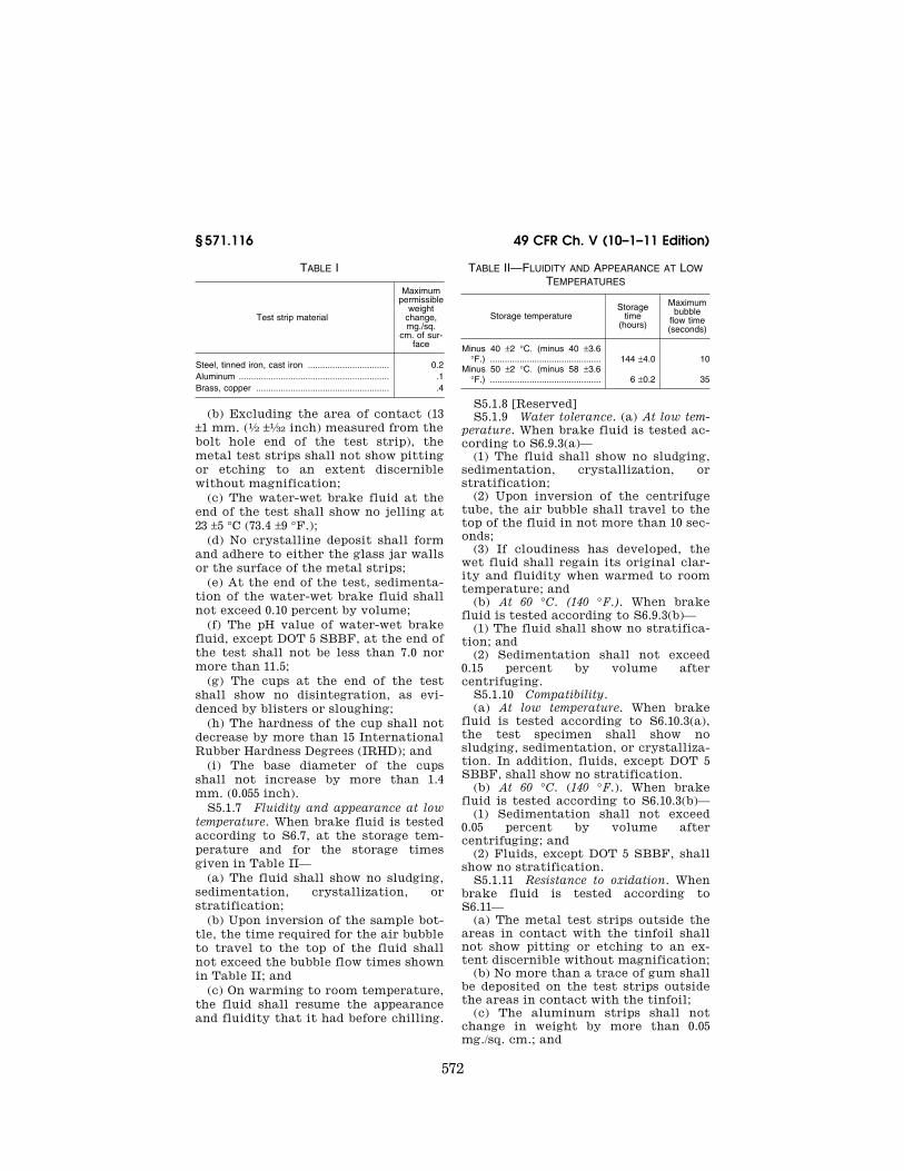
TABLE I
Test strip material
Maximum permissible
weight change, mg./sq.
cm. of sur-face
Steel, tinned iron, cast iron ................................. 0.2 Aluminum ............................................................. .1 Brass, copper ...................................................... .4
(b) Excluding the area of contact (13 ±1 mm. (1⁄2 ±1⁄32 inch) measured from the bolt hole end of the test strip), the metal test strips shall not show pitting or etching to an extent discernible without magnification;
(c) The water-wet brake fluid at the end of the test shall show no jelling at 23 ±5 °C (73.4 ±9 °F.);
(d) No crystalline deposit shall form and adhere to either the glass jar walls or the surface of the metal strips;
(e) At the end of the test, sedimenta-tion of the water-wet brake fluid shall not exceed 0.10 percent by volume;
(f) The pH value of water-wet brake fluid, except DOT 5 SBBF, at the end of the test shall not be less than 7.0 nor more than 11.5;
(g) The cups at the end of the test shall show no disintegration, as evi-denced by blisters or sloughing;
(h) The hardness of the cup shall not decrease by more than 15 International Rubber Hardness Degrees (IRHD); and
(i) The base diameter of the cups shall not increase by more than 1.4 mm. (0.055 inch).
S5.1.7 Fluidity and appearance at low temperature. When brake fluid is tested according to S6.7, at the storage tem-perature and for the storage times given in Table II—
(a) The fluid shall show no sludging, sedimentation, crystallization, or stratification;
(b) Upon inversion of the sample bot-tle, the time required for the air bubble to travel to the top of the fluid shall not exceed the bubble flow times shown in Table II; and
(c) On warming to room temperature, the fluid shall resume the appearance and fluidity that it had before chilling.
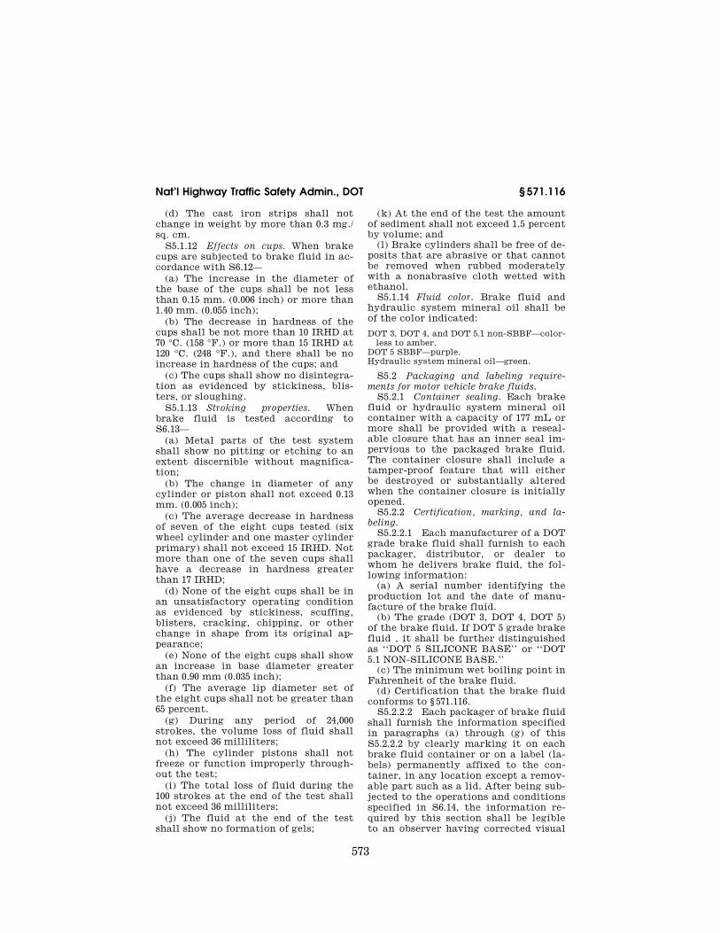
TABLE II—FLUIDITY AND APPEARANCE AT LOW TEMPERATURES
Storage temperature Storage
time (hours)
Maximum bubble
flow time (seconds)
Minus 40 ±2 °C. (minus 40 ±3.6 °F.) ............................................. 144 ±4.0 10
Minus 50 ±2 °C. (minus 58 ±3.6 °F.) ............................................. 6 ±0.2 35
S5.1.8 [Reserved] S5.1.9 Water tolerance. (a) At low tem-
perature. When brake fluid is tested ac-cording to S6.9.3(a)—
(1) The fluid shall show no sludging, sedimentation, crystallization, or stratification;
(2) Upon inversion of the centrifuge tube, the air bubble shall travel to the top of the fluid in not more than 10 sec-onds;
(3) If cloudiness has developed, the wet fluid shall regain its original clar-ity and fluidity when warmed to room temperature; and
(b) At 60 °C. (140 °F.). When brake fluid is tested according to S6.9.3(b)—
(1) The fluid shall show no stratifica-tion; and
(2) Sedimentation shall not exceed 0.15 percent by volume after centrifuging.
S5.1.10 Compatibility. (a) At low temperature. When brake
fluid is tested according to S6.10.3(a), the test specimen shall show no sludging, sedimentation, or crystalliza-tion. In addition, fluids, except DOT 5 SBBF, shall show no stratification.
(b) At 60 °C. (140 °F.). When brake fluid is tested according to S6.10.3(b)—
(1) Sedimentation shall not exceed 0.05 percent by volume after centrifuging; and
(2) Fluids, except DOT 5 SBBF, shall show no stratification.
S5.1.11 Resistance to oxidation. When brake fluid is tested according to S6.11—
(a) The metal test strips outside the areas in contact with the tinfoil shall not show pitting or etching to an ex-tent discernible without magnification;
(b) No more than a trace of gum shall be deposited on the test strips outside the areas in contact with the tinfoil;
(c) The aluminum strips shall not change in weight by more than 0.05 mg./sq. cm.; and
VerDate Mar<15>2010 18:42 Dec 22, 2011 Jkt 223219 PO 00000 Frm 00582 Fmt 8010 Sfmt 8010 Q:\49\X49\223219.XXX ofr150 PsN: PC150
573
Nat’l Highway Traffic Safety Admin., DOT § 571.116
(d) The cast iron strips shall not change in weight by more than 0.3 mg./ sq. cm.
S5.1.12 Effects on cups. When brake cups are subjected to brake fluid in ac-cordance with S6.12—
(a) The increase in the diameter of the base of the cups shall be not less than 0.15 mm. (0.006 inch) or more than 1.40 mm. (0.055 inch);
(b) The decrease in hardness of the cups shall be not more than 10 IRHD at 70 °C. (158 °F.) or more than 15 IRHD at 120 °C. (248 °F.), and there shall be no increase in hardness of the cups; and
(c) The cups shall show no disintegra-tion as evidenced by stickiness, blis-ters, or sloughing.
S5.1.13 Stroking properties. When brake fluid is tested according to S6.13—
(a) Metal parts of the test system shall show no pitting or etching to an extent discernible without magnifica-tion;
(b) The change in diameter of any cylinder or piston shall not exceed 0.13 mm. (0.005 inch);
(c) The average decrease in hardness of seven of the eight cups tested (six wheel cylinder and one master cylinder primary) shall not exceed 15 IRHD. Not more than one of the seven cups shall have a decrease in hardness greater than 17 IRHD;
(d) None of the eight cups shall be in an unsatisfactory operating condition as evidenced by stickiness, scuffing, blisters, cracking, chipping, or other change in shape from its original ap-pearance;
(e) None of the eight cups shall show an increase in base diameter greater than 0.90 mm (0.035 inch);
(f) The average lip diameter set of the eight cups shall not be greater than 65 percent.
(g) During any period of 24,000 strokes, the volume loss of fluid shall not exceed 36 milliliters;
(h) The cylinder pistons shall not freeze or function improperly through-out the test;
(i) The total loss of fluid during the 100 strokes at the end of the test shall not exceed 36 milliliters;
(j) The fluid at the end of the test shall show no formation of gels;
(k) At the end of the test the amount of sediment shall not exceed 1.5 percent by volume; and
(l) Brake cylinders shall be free of de-posits that are abrasive or that cannot be removed when rubbed moderately with a nonabrasive cloth wetted with ethanol.
S5.1.14 Fluid color. Brake fluid and hydraulic system mineral oil shall be of the color indicated:
DOT 3, DOT 4, and DOT 5.1 non-SBBF—color-less to amber.
DOT 5 SBBF—purple. Hydraulic system mineral oil—green.
S5.2 Packaging and labeling require-ments for motor vehicle brake fluids.
S5.2.1 Container sealing. Each brake fluid or hydraulic system mineral oil container with a capacity of 177 mL or more shall be provided with a reseal-able closure that has an inner seal im-pervious to the packaged brake fluid. The container closure shall include a tamper-proof feature that will either be destroyed or substantially altered when the container closure is initially opened.
S5.2.2 Certification, marking, and la-beling.
S5.2.2.1 Each manufacturer of a DOT grade brake fluid shall furnish to each packager, distributor, or dealer to whom he delivers brake fluid, the fol-lowing information:
(a) A serial number identifying the production lot and the date of manu-facture of the brake fluid.
(b) The grade (DOT 3, DOT 4, DOT 5) of the brake fluid. If DOT 5 grade brake fluid , it shall be further distinguished as ‘‘DOT 5 SILICONE BASE’’ or ‘‘DOT 5.1 NON-SILICONE BASE.’’
(c) The minimum wet boiling point in Fahrenheit of the brake fluid.
(d) Certification that the brake fluid conforms to § 571.116.
S5.2.2.2 Each packager of brake fluid shall furnish the information specified in paragraphs (a) through (g) of this S5.2.2.2 by clearly marking it on each brake fluid container or on a label (la-bels) permanently affixed to the con-tainer, in any location except a remov-able part such as a lid. After being sub-jected to the operations and conditions specified in S6.14, the information re-quired by this section shall be legible to an observer having corrected visual
VerDate Mar<15>2010 18:42 Dec 22, 2011 Jkt 223219 PO 00000 Frm 00583 Fmt 8010 Sfmt 8010 Q:\49\X49\223219.XXX ofr150 PsN: PC150
574
49 CFR Ch. V (10–1–11 Edition) § 571.116
acuity of 20/40 (Snellen ratio) at a dis-tance of 305 mm, and any label affixed to the container in compliance with this section shall not be removable without its being destroyed or defaced.
(a) Certification that the brake fluid conforms to § 571.116.
(b) The name of the packager of the brake fluid, which may be in code form.
(c) The name and complete mailing address of the distributor.
(d) A serial number identifying the packaged lot and date of packaging.
(e) Designation of the contents as ‘‘DOT—MOTOR VEHICLE BRAKE FLUID’’ (Fill in DOT 3, DOT 4, DOT 5 SILICONE BASE, or DOT 5.1 NON-SIL-ICONE BASE as applicable).
(f) The minimum wet boiling point in Fahrenheit of the DOT brake fluid in the container.
(g) The following safety warnings in capital and lower case letters as indi-cated:
(1) FOLLOW VEHICLE MANUFAC-TURER’S RECOMMENDATIONS WHEN ADDING BRAKE FLUID.
(2) KEEP BRAKE FLUID CLEAN AND DRY. Contamination with dirt, water, petroleum products or other ma-terials may result in brake failure or costly repairs.
(3) STORE BRAKE FLUID ONLY IN ITS ORIGINAL CONTAINER. KEEP CONTAINER CLEAN AND TIGHTLY CLOSED TO PREVENT ABSORPTION OF MOISTURE.
(4) CAUTION: DO NOT REFILL CON-TAINER, AND DO NOT USE FOR OTHER LIQUIDS. (Not required for containers with a capacity in excess of 19 L.)
S5.2.2.3 Each packager of hydraulic system mineral oil shall furnish the in-formation specified in paragraphs (a) through (e) of this S5.2.2.3 by clearly marking it on each brake fluid con-tainer or on a label (labels) perma-nently affixed to the container, in any location except a removable part such as a lid. After being subjected to the operations and conditions specified in S6.14, the information required by this section shall be legible to an observer having corrected visual acuity of 20/40 (Snellen ratio) at a distance of 305 mm and any label affixed to the container in compliance with this section shall
not be removable without its being de-stroyed or defaced.
(a) The name of the packager of the hydraulic system mineral oil, which may be in code form.
(b) The name and complete mailing address of the distributor.
(c) A serial number identifying the packaged lot and date of packaging.
(d) Designation of the contents as ‘‘HYDRAULIC SYSTEM MINERAL OIL’’ in capital letters at least 3 mm high.
(e) The following safety warnings in capital and lower case letters as indi-cated:
(1) FOLLOW VEHICLE MANUFAC-TURER’S RECOMMENDATIONS WHEN ADDING HYDRAULIC SYSTEM MINERAL OIL.
(2) Hydraulic System Mineral Oil is NOT COMPATIBLE with the rubber components of brake systems designed for use with DOT brake fluids.
(3) KEEP HYDRAULIC SYSTEM MINERAL OIL CLEAN. Contamination with dust or other materials may re-sult in brake failure or costly repair.
(4) CAUTION: STORE HYDRAULIC SYSTEM MINERAL OIL ONLY IN ITS ORIGINAL CONTAINER. KEEP CON-TAINER CLEAN AND TIGHTLY CLOSED. DO NOT REFILL CON-TAINER OR USE OTHER LIQUIDS. (The last sentence is not required for containers with a capacity in excess of 19 L.)
S5.2.2.4 If a container for brake fluid or hydraulic system mineral oil is not normally visible but designed to be protected by an outer container or car-ton during use, the outer container or carton rather than the inner container shall meet the labeling requirements of S5.2.2.2 or S5.2.2.3, as appropriate.
S5.3 Motor vehicle requirement. Each passenger car, multipurpose passenger vehicle, truck, bus, trailer, and motor-cycle that has a hydraulic brake sys-tem shall be equipped with fluid that has been manufactured and packaged in conformity with the requirements of this standard.
S6. Test procedures. S6.1 Equilibrium reflux boiling point.
Determine the ERBP of a brake fluid by running duplicate samples accord-ing to the following procedure and averaging the results.
VerDate Mar<15>2010 18:42 Dec 22, 2011 Jkt 223219 PO 00000 Frm 00584 Fmt 8010 Sfmt 8010 Q:\49\X49\223219.XXX ofr150 PsN: PC150
575
Nat’l Highway Traffic Safety Admin., DOT § 571.116
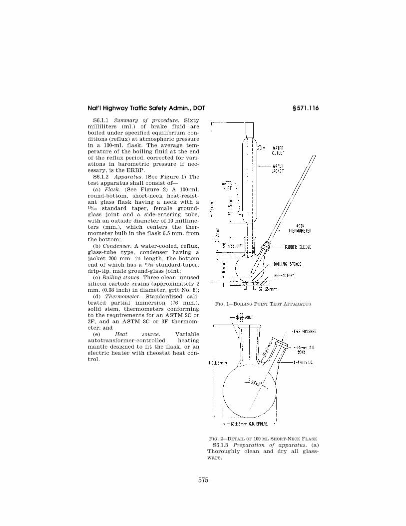
S6.1.1 Summary of procedure. Sixty milliliters (ml.) of brake fluid are boiled under specified equilibrium con-ditions (reflux) at atmospheric pressure in a 100-ml. flask. The average tem-perature of the boiling fluid at the end of the reflux period, corrected for vari-ations in barometric pressure if nec-essary, is the ERBP.
S6.1.2 Apparatus. (See Figure 1) The test apparatus shall consist of—
(a) Flask. (See Figure 2) A 100-ml. round-bottom, short-neck heat-resist-ant glass flask having a neck with a 19⁄38 standard taper, female ground- glass joint and a side-entering tube, with an outside diameter of 10 millime-ters (mm.), which centers the ther-mometer bulb in the flask 6.5 mm. from the bottom;
(b) Condenser. A water-cooled, reflux, glass-tube type, condenser having a jacket 200 mm. in length, the bottom end of which has a 19⁄38 standard-taper, drip-tip, male ground-glass joint;
(c) Boiling stones. Three clean, unused silicon carbide grains (approximately 2 mm. (0.08 inch) in diameter, grit No. 8);
(d) Thermometer. Standardized cali-brated partial immersion (76 mm.), solid stem, thermometers conforming to the requirements for an ASTM 2C or 2F, and an ASTM 3C or 3F thermom-eter; and
(e) Heat source. Variable autotransformer-controlled heating mantle designed to fit the flask, or an electric heater with rheostat heat con-trol.
FIG. 1—BOILING POINT TEST APPARATUS
FIG. 2—DETAIL OF 100 ML SHORT-NECK FLASK S6.1.3 Preparation of apparatus. (a)
Thoroughly clean and dry all glass-ware.
VerDate Mar<15>2010 18:42 Dec 22, 2011 Jkt 223219 PO 00000 Frm 00585 Fmt 8010 Sfmt 8010 Q:\49\X49\223219.XXX ofr150 PsN: PC150 EC
01A
U91
.043
EC
01A
U91
.044
576
49 CFR Ch. V (10–1–11 Edition) § 571.116
(b) Insert thermometer through the side tube until the tip of the bulb is 6.5 mm. (1⁄4 inch) from the bottom center of the flask. Seal with a short piece of natural rubber, EPDM, SBR, or butyl tubing.
(c) Place 60 ±1 ml. of brake fluid and the silicon carbide grains into the flask.
(d) Attach the flask to the condenser. When using a heating mantle, place the mantle under the flask and support it with a ring-clamp and laboratory-type stand, holding the entire assembly in place by a clamp. When using a rheo-stat-controlled heater, center a stand-ard porcelain or hard asbestos refrac-tory, having a diameter opening 32 to 38 mm., over the heating element and mount the flask so that direct heat is applied only through the opening in the refractory. Place the assembly in an area free from drafts or other types of sudden temperature changes. Con-nect the cooling water inlet and outlet tubes to the condenser. Turn on the cooling water. The water supply tem-perature shall not exceed 28 °C. (82.4 °F.) and the temperature rise through the condenser shall not exceed 2 °C. (3.6 °F.).
S6.1.4 Procedure. Apply heat to the flask so that within 10 ±2 minutes the fluid is refluxing in excess of 1 drop per second. The reflux rate shall not exceed 5 drops per second at any time. Imme-diately adjust the heating rate to ob-tain an equilibrium reflux rate of 1 to 2 drops per second over the next 5 ±2 minutes. Maintain this rate for an ad-ditional 2 minutes, taking four tem-perature readings at 30–second inter-vals. Record the average of these as the observed ERBP. If no reflux is evident when the fluid temperature reaches 260 °C (500 °F), discontinue heating and re-port ERBP as in excess of 260 °C (500 °F).
S6.1.5 Calculation. (a) Thermometer inaccuracy. Correct the observed ERBP by applying any correction factor ob-tained in standardizing the thermom-eter.
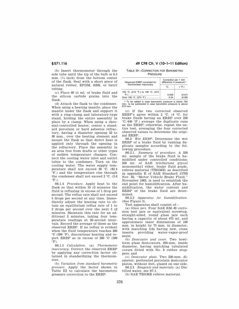
(b) Variation from standard barometric pressure. Apply the factor shown in Table III to calculate the barometric pressure correction to the ERBP.
TABLE III—CORRECTION FOR BAROMETRIC PRESSURE
Observed ERBP corrected for thermometer inaccuracy
Correction per 1 mm difference in pressure a
°C. ( °F.)
100 °C. (212 °F.) to 190 °C. (374 °F.) ............................................. 0.039 (0.07)
Over 190 °C. (374 °F.) .................. 0.04 (0.08)
a To be added in case barometric pressure is below 760 mm.; to be subtracted in case barometric pressure is above 670 mm.
(c) If the two corrected observed ERBP’s agree within 2 °C. (4 °C. for brake fluids having an ERBP over 230 °C./446 °F.) average the duplicate runs as the ERBP; otherwise, repeat the en-tire test, averaging the four corrected observed values to determine the origi-nal ERBP.
S6.2 Wet ERBP. Determine the wet ERBP of a brake fluid by running du-plicate samples according to the fol-lowing procedure.
S6.2.1. Summary of procedure. A 350 ml. sample of the brake fluid is hu-midified under controlled conditions; 350 ml. of SAE triethylene glycol monomethyl ether, brake fluid grade, referee material (TEGME) as described in appendix E of SAE Standard J1703 Nov. 83, ‘‘Motor Vehicle Brake Fluid,’’ November 1983, is used to establish the end point for humidification. After hu-midification, the water content and ERBP of the brake fluid are deter-mined.
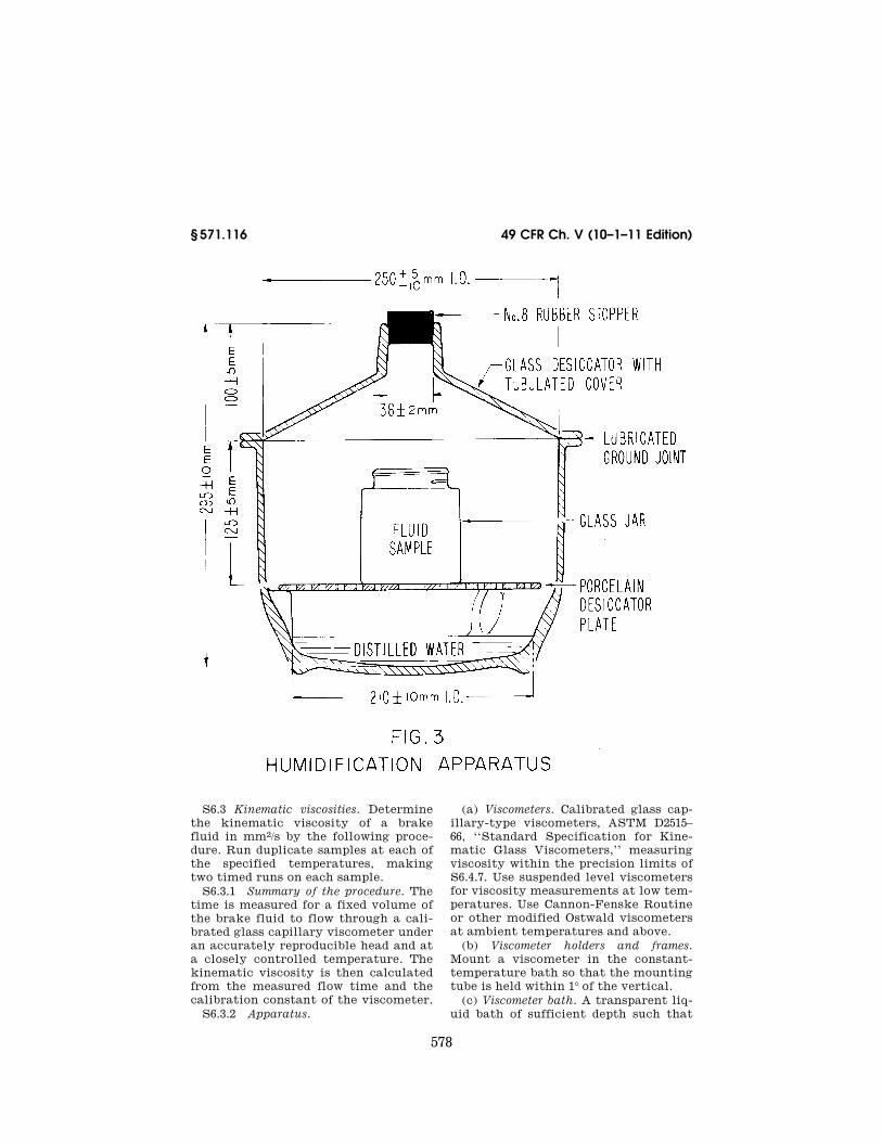
S6.2.2 Apparatus for humidification. (See Figure 3).
Test apparatus shall consist of— (a) Glass jars. Four SAE RM–49 corro-
sion test jars or equivalent screwtop, straight-sided, round glass jars each having a capacity of about 475 ml. and approximate inner dimensions of 100 mm. in height by 75 mm. in diameter, with matching lids having new, clean inserts providing water-vapor-proof seals;
(b) Desiccator and cover. Two bowl- form glass desiccators, 250-mm. inside diameter, having matching tubulated covers fitted with No. 8 rubber stop-pers; and
(c) Desiccator plate. Two 230-mm. di-ameter, perforated porcelain desiccator plates, without feet, glazed on one side.
S6.2.3 Reagents and materials. (a) Dis-tilled water, see S7.1.
(b) SAE TEGME referee material.
VerDate Mar<15>2010 18:42 Dec 22, 2011 Jkt 223219 PO 00000 Frm 00586 Fmt 8010 Sfmt 8010 Q:\49\X49\223219.XXX ofr150 PsN: PC150
577
Nat’l Highway Traffic Safety Admin., DOT § 571.116
S6.2.4 Preparation of apparatus. Lu-bricate the ground-glass joint of the desiccator. Pour 450 ±10 ml. of distilled water into each desiccator and insert perforated porcelain desiccator plates. Place the desiccators in an oven with temperature controlled at 50 ±1 °C. (122 ±1.8 °F.) throughout the humidification procedure.
S6.2.5 Procedure. Pour 350 ±5 ml. of brake fluid into an open corrosion test jar. Prepare in the same manner a du-plicate test fluid sample and two dupli-cate specimens of the SAE TEGME ref-eree material (350 ±5 ml. of TEGME in each jar). The water content of the SAE TEGME fluid is adjusted to 0.50 ±0.05 percent by weight at the start of the test in accordance with S7.2. Place one sample each of the test brake fluid and the prepared TEGME sample into the same desiccator. Repeat for the second sample of test brake fluid and TEGME in a second desiccator. Place the desiccators in the 50 °C. (122 °F.) controlled oven and replace desiccator
covers. At intervals, during oven hu-midification, remove the rubber stop-pers in the tops of desiccators. Using a long needled hypodermic syringe, take a sample of not more than 2 ml. from each TEGME sample and determine its water content. Remove no more than 10 ml. of fluid from each SAE TEGME sample during the humidification pro-cedure. When the water content of the SAE fluid reaches 3.70 ±0.05 percent by weight (average of the duplicates). re-move the two test fluid specimens from their desiccators and promptly cap each jar tightly. Allow the sealed jars to cool for 60 to 90 minutes at 23° ±5 °C. (73.4° ±9 °F.). Measure the water con-tents of the test fluid specimens in ac-cordance with S7.2 and determine their ERBP’s in accordance with S6.1. If the two ERBPs agree within 4 °C. (8 °F.), average them to determine the wet ERBP; otherwise repeat and average the four individual ERBPs as the wet ERBP of the brake fluid.
VerDate Mar<15>2010 18:42 Dec 22, 2011 Jkt 223219 PO 00000 Frm 00587 Fmt 8010 Sfmt 8010 Q:\49\X49\223219.XXX ofr150 PsN: PC150
578
49 CFR Ch. V (10–1–11 Edition) § 571.116
S6.3 Kinematic viscosities. Determine the kinematic viscosity of a brake fluid in mm2/s by the following proce-dure. Run duplicate samples at each of the specified temperatures, making two timed runs on each sample.
S6.3.1 Summary of the procedure. The time is measured for a fixed volume of the brake fluid to flow through a cali-brated glass capillary viscometer under an accurately reproducible head and at a closely controlled temperature. The kinematic viscosity is then calculated from the measured flow time and the calibration constant of the viscometer.
S6.3.2 Apparatus.
(a) Viscometers. Calibrated glass cap-illary-type viscometers, ASTM D2515– 66, ‘‘Standard Specification for Kine-matic Glass Viscometers,’’ measuring viscosity within the precision limits of S6.4.7. Use suspended level viscometers for viscosity measurements at low tem-peratures. Use Cannon-Fenske Routine or other modified Ostwald viscometers at ambient temperatures and above.
(b) Viscometer holders and frames. Mount a viscometer in the constant- temperature bath so that the mounting tube is held within 1° of the vertical.
(c) Viscometer bath. A transparent liq-uid bath of sufficient depth such that
VerDate Mar<15>2010 18:42 Dec 22, 2011 Jkt 223219 PO 00000 Frm 00588 Fmt 8010 Sfmt 8010 Q:\49\X49\223219.XXX ofr150 PsN: PC150 EC
01A
U91
.045
</G
PH
>
579
Nat’l Highway Traffic Safety Admin., DOT § 571.116
at no time during the measurement will any portion of the sample in the viscometer be less than 2 cm. below the surface or less than 2 cm. above the bottom. The bath shall be cylindrical in shape, with turbulent agitation suf-ficient to meet the temperature con-trol requirements. For measurements within 15° to 100 °C. (60° to 212 °F.) the temperature of the bath medium shall not vary by more than 0.01 °C. (0.02 °F.) over the length of the viscometers, or between the positions of the viscometers, or at the locations of the
thermometers. Outside this range, the variation shall not exceed 0.03 °C. (0.05 °F.).
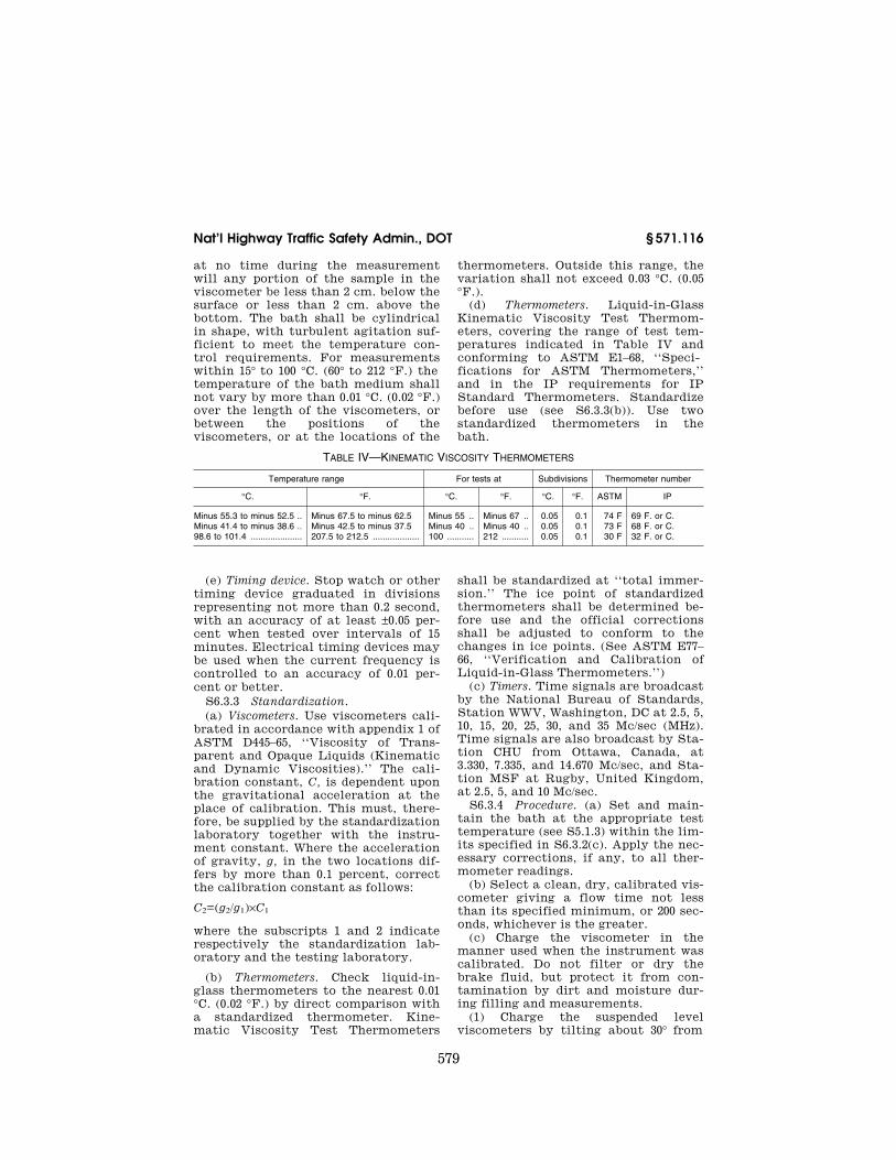
(d) Thermometers. Liquid-in-Glass Kinematic Viscosity Test Thermom-eters, covering the range of test tem-peratures indicated in Table IV and conforming to ASTM E1–68, ‘‘Speci-fications for ASTM Thermometers,’’ and in the IP requirements for IP Standard Thermometers. Standardize before use (see S6.3.3(b)). Use two standardized thermometers in the bath.
TABLE IV—KINEMATIC VISCOSITY THERMOMETERS
Temperature range For tests at Subdivisions Thermometer number
°C. °F. °C. °F. °C. °F. ASTM IP
Minus 55.3 to minus 52.5 .. Minus 67.5 to minus 62.5 Minus 55 .. Minus 67 .. 0.05 0.1 74 F 69 F. or C. Minus 41.4 to minus 38.6 .. Minus 42.5 to minus 37.5 Minus 40 .. Minus 40 .. 0.05 0.1 73 F 68 F. or C. 98.6 to 101.4 ..................... 207.5 to 212.5 ................... 100 ........... 212 ........... 0.05 0.1 30 F 32 F. or C.
(e) Timing device. Stop watch or other timing device graduated in divisions representing not more than 0.2 second, with an accuracy of at least ±0.05 per-cent when tested over intervals of 15 minutes. Electrical timing devices may be used when the current frequency is controlled to an accuracy of 0.01 per-cent or better.
S6.3.3 Standardization. (a) Viscometers. Use viscometers cali-
brated in accordance with appendix 1 of ASTM D445–65, ‘‘Viscosity of Trans-parent and Opaque Liquids (Kinematic and Dynamic Viscosities).’’ The cali-bration constant, C, is dependent upon the gravitational acceleration at the place of calibration. This must, there-fore, be supplied by the standardization laboratory together with the instru-ment constant. Where the acceleration of gravity, g, in the two locations dif-fers by more than 0.1 percent, correct the calibration constant as follows:
C2=(g2/g1)×C1
where the subscripts 1 and 2 indicate respectively the standardization lab-oratory and the testing laboratory.
(b) Thermometers. Check liquid-in- glass thermometers to the nearest 0.01 °C. (0.02 °F.) by direct comparison with a standardized thermometer. Kine-matic Viscosity Test Thermometers
shall be standardized at ‘‘total immer-sion.’’ The ice point of standardized thermometers shall be determined be-fore use and the official corrections shall be adjusted to conform to the changes in ice points. (See ASTM E77– 66, ‘‘Verification and Calibration of Liquid-in-Glass Thermometers.’’)
(c) Timers. Time signals are broadcast by the National Bureau of Standards, Station WWV, Washington, DC at 2.5, 5, 10, 15, 20, 25, 30, and 35 Mc/sec (MHz). Time signals are also broadcast by Sta-tion CHU from Ottawa, Canada, at 3.330, 7.335, and 14.670 Mc/sec, and Sta-tion MSF at Rugby, United Kingdom, at 2.5, 5, and 10 Mc/sec.
S6.3.4 Procedure. (a) Set and main-tain the bath at the appropriate test temperature (see S5.1.3) within the lim-its specified in S6.3.2(c). Apply the nec-essary corrections, if any, to all ther-mometer readings.
(b) Select a clean, dry, calibrated vis-cometer giving a flow time not less than its specified minimum, or 200 sec-onds, whichever is the greater.
(c) Charge the viscometer in the manner used when the instrument was calibrated. Do not filter or dry the brake fluid, but protect it from con-tamination by dirt and moisture dur-ing filling and measurements.
(1) Charge the suspended level viscometers by tilting about 30° from
VerDate Mar<15>2010 18:42 Dec 22, 2011 Jkt 223219 PO 00000 Frm 00589 Fmt 8010 Sfmt 8010 Q:\49\X49\223219.XXX ofr150 PsN: PC150
580
49 CFR Ch. V (10–1–11 Edition) § 571.116
the vertical and pouring sufficient brake fluid through the fill tube into the lower reservoir so that when the viscometer is returned to vertical posi-tion the meniscus is between the fill marks. For measurements below 0 °C. (32 °F.), before placing the filled vis-cometer into the constant temperature bath, draw the sample into the working capillary and timing bulb and insert small rubber stoppers to suspend the fluid in this position, to prevent accu-mulation of water condensate on the walls of the critical portions of the vis-cometer. Alternatively, fit loosely packed drying tubes into the open ends of the viscometer to prevent water con-densation, but do not restrict the flow of the sample under test by the pres-sures created in the instrument.
(2) If a Cannon-Fenske Routine vis-cometer is used, charge by inverting and immersing the smaller arm into the brake fluid and applying vacuum to the larger arm. Fill the tube to the upper timing mark, and return the vis-cometer to an upright position.
(d) Mount the viscometer in the bath in a true vertical position (see S6.3.2(b)).
(e) The viscometer shall remain in the bath until it reaches the test tem-perature.
(f) At temperatures below 0 °C. (32 °F.) conduct an untimed preliminary run by allowing the brake fluid to drain through the capillary into the lower reservoir after the test tempera-ture has been established.
(g) Adjust the head level of the brake fluid to a position in the capillary arm about 5 mm. above the first timing mark.
(h) With brake fluid flowing freely measure to within 0.2 second the time required for the meniscus to pass from the first timing mark to the second. If this flow time is less than the min-imum specified for the viscometer, or 200 seconds, whichever is greater, re-peat using a viscometer with a cap-illary of smaller diameter.
(i) Repeat S6.3.4 (g) and (h). If the two timed runs do not agree within 0.2 percent, reject and repeat using a fresh sample of brake fluid.
S6.3.5 Cleaning the viscometers. (a) Periodically clean the instrument with chromic acid to remove organic depos-
its. Rinse thoroughly with distilled water and acetone, and dry with clean dry air.
(b) Between successive samples rinse the viscometer with ethanol (isopropanol when testing DOT 5 fluids) followed by an acetone or ether rinse. Pass a slow stream of filtered dry air through the viscometer until the last trace of solvent is removed.
S6.3.6 Calculation. (a) The following viscometers have a fixed volume charged at ambient temperature, and as a consequence C varies with test temperature: Cannon-Fenske Routine, Pinkevitch, Cannon-Manning Semi- Micro, and Cannon Fenske Opaque. To calculate C at test temperatures other than the calibration temperature for these viscometers, see ASTM D2515–66, ‘‘Kinematic Glass Viscometers’’ or fol-low instructions given on the manufac-turer’s certificate of calibration.
(b) Average the four timed runs on the duplicate samples to determine the kinematic viscosities.
S6.3.7 Precision (at 95 percent con-fidence level).
(a) Repeatability. If results on dupli-cate samples by the same operator dif-fer by more than 1 percent of their mean, repeat the tests.
S6.4 pH value. Determine the pH value of a brake fluid by running one sample according to the following pro-cedure.
S6.4.1 Summary of the procedure. Brake fluid is diluted with an equal volume of an ethanol-water solution. The pH of the resultant mixture is measured with a prescribed pH meter assembly at 23 °C. (73.4 °F.).
S6.4.2 Apparatus. The pH assembly consists of the pH meter, glass elec-trode, and calomel electrode, as speci-fied in Appendices A1.1, A1.2, and A1.3 of ASTM D 1121–67, ‘‘Standard Method of Test for Reserve Alkalinity of En-gine Antifreezes and Antirusts.’’ The glass electrode is a full range type (pH 0–14), with low sodium error.
S6.4.3 Reagents. Reagent grade chemicals conforming to the specifica-tions of the Committee on Analytical Reagents of the American Chemical Society.
VerDate Mar<15>2010 18:42 Dec 22, 2011 Jkt 223219 PO 00000 Frm 00590 Fmt 8010 Sfmt 8010 Q:\49\X49\223219.XXX ofr150 PsN: PC150
581
Nat’l Highway Traffic Safety Admin., DOT § 571.116
(a) Distilled water. Distilled water (S7.1) shall be boiled for about 15 min-utes to remove carbon dioxide, and pro-tected with a soda-lime tube or its equivalent while cooling and in stor-age. (Take precautions to prevent con-tamination by the materials used for protection against carbon dioxide.) The pH of the boiled distilled water shall be between 6.2 and 7.2 at 25 °C. (77 °F.).
(b) Standard buffer solutions. Prepare buffer solutions for calibrating the pH meter and electrode pair from salts sold specifically for use, either singly or in combination, as pH standards. Dry salts for 1 hour at 110 °C. (230 °F.) before use except for borax which shall be used as the decahydrate. Store solu-tions with pH less than 9.5 in bottles of chemically resistant glass or poly-ethylene. Store the alkaline phosphate solution in a glass bottle coated inside with paraffin. Do not use a standard with an age exceeding three months.
(1) Potassium hydrogen phthalate buffer solution (0.05 M, pH=4.01 at 25 °C. (77 °F.)). Dissolve 10.21 g. of potassium hydrogen phthalate (KHC8 H4 O4) in dis-tilled water. Dilute to 1 liter.
(2) Neutral phosphate buffer solution (0.025 M with respect to each phosphate salt, pH=6.86 at 25 °C. (77 °F.)). Dissolve 3.40 g. of potassium dihydrogen phos-phate (KH2 PO4) and 3.55 g. of anhy-drous disodium hydrogen phosphate (Na2 HPO4) in distilled water.
(3) Borax buffer solution (0.01 M, pH=9.18 at 25 °C. (77 °F.)). Dissolve 3.81 g. of disodium tetraborate decahydrate (Na2 B4 O7°10H2O) in distilled water, and dilute to 1 liter. Stopper the bottle except when actually in use.
(4) Alkaline phosphate buffer solu-tion (0.01 M trisodium phosphate, pH=11.72 at 25 °C. (77 °F.)). Dissolve 1.42 g. of anhydrous disodium hydrogen phosphate (Na2 HPO4) in 100 ml. of a 0.1 M carbonate-free solution of sodium hydroxide. Dilute to 1 liter with dis-tilled water.
(5) Potassium chloride electrolyte. Prepare a saturated solution of potas-sium chloride (KCl) in distilled water.
(c) Ethanol-water mixture. To 80 parts by volume of ethanol (S7.3) add 20 parts by volume of distilled water. Adjust the pH of the mixture to 7 ±0.1 using 0.1 N sodium hydroxide (NaOH) solution. If more than 4 ml. of NaOH solution per
liter of mixture is required for neutral-ization, discard the mixture.
S6.4.4 Preparation of electrode system. (a) Maintenance of electrodes. Clean
the glass electrode before using by im-mersing in cold chromic-acid cleaning solution. Drain the calomel electrode and fill with KCl electrolyte, keeping level above that of the mixture at all times. When not in use, immerse the lower halves of the electrodes in dis-tilled water, and do not immerse in the mixture for any appreciable period of time between determinations.
(b) Preparation of electrodes. Condition new glass electrodes and those that have been stored dry as recommended by the manufacturer. Before and after using, wipe the glass electrode thor-oughly with a clean cloth, or a soft ab-sorbent tissue, and rinse with distilled water. Before each pH determination, soak the prepared electrode in distilled water for at least 2 minutes. Imme-diately before use, remove any excess water from the tips of the electrode.
S6.4.5 Standardization of the pH as-sembly and testing of the electrodes. (a) Immediately before use, standardize the pH assembly with a standard buffer solution. Then use a second standard buffer solution to check the linearity of the response of the electrodes at dif-ferent pH values, and to detect a faulty glass electrode or incorrect tempera-ture compensation. The two buffer so-lutions bracket the anticipated pH value of the test brake fluid.
(b) Allow instrument to warm up, and adjust according to the manufac-turer’s instructions. Immerse the tips of the electrodes in a standard buffer solution and allow the temperature of the buffer solution and the electrodes to equalize. Set the temperature knob at the temperature of the buffer solu-tion. Adjust the standardization or asymmetry potential control until the meter registers a scale reading, in pH units, equal to the known pH of the standardizing buffer solution.
(c) Rinse the electrodes with distilled water and remove excess water from the tips. Immerse the electrodes in a second standard buffer solution. The reading of the meter shall agree with the known pH of the second standard
VerDate Mar<15>2010 18:42 Dec 22, 2011 Jkt 223219 PO 00000 Frm 00591 Fmt 8010 Sfmt 8010 Q:\49\X49\223219.XXX ofr150 PsN: PC150
582
49 CFR Ch. V (10–1–11 Edition) § 571.116
buffer solution within ±0.05 unit with-out changing the setting of the stand-ardization of asymmetry potential con-trol.
(d) A faulty electrode is indicated by failure to obtain a correct value for the pH of the second standard buffer solu-tion after the meter has been standard-ized with the first.
S6.4.6 Procedure. To 50 ±1 ml. of the test brake fluid add 50 ±1 ml. of the ethanol-water (S6.4.3(c)) and mix thor-oughly. Immerse the electrodes in the mixture. Allow the system to come to equilibrium, readjust the temperature compensation if necessary, and take the pH reading.
S6.5 Fluid stability. Evaluate the heat and chemical stability of a brake fluid by the following procedure, run-ning duplicate samples for each test and averaging the results.
S6.5.1 Summary of the procedure. The degradation of the brake fluid at ele-vated temperature, alone or in a mix-ture with a reference fluid, is evaluated by determining the change in boiling point after a period of heating under reflux conditions.
S6.5.2 Apparatus. Use the apparatus and preparation specified in S6.1.2 and S6.1.3.
S6.5.3 High temperature stability. S6.5.3.1 Procedure. (a) Heat a new 60
±1 ml. sample of the brake fluid to 185° ±2 °C. (365° ±3.6 °F.). Hold at this tem-perature for 120 ±5 minutes. Bring to a reflux rate in excess of 1 drop per sec-ond within 5 minutes. The reflux rate should not exceed 5 drops per second at any time. Over the next 5 ±2 minutes adjust the heating rate to obtain an equilibrium reflux rate of 1 to 2 drops per second. Maintain this rate for an additional 2 minutes, taking four tem-perature readings at 30–second inter-vals. Average these as the observed ERBP. If no reflux is evident when the fluid temperature reaches 260 °C. (500 °F), discontinue heating and report ERBP as in excess of 260 °C. (500 °F.).
S6.5.3.2 Calculation. Correct the ob-served ERBP for thermometer and bar-ometric pressure factors according to S6.1.5 (a) and (b). Average the corrected ERBP’s of the duplicate samples. The difference between this average and the original ERBP obtained in S6.1 is the change in ERBP of the fluid.
S6.5.4 Chemical stability. S6.5.4.1 Materials. SAE RM–66–04
Compatibility Fluid as described in ap-pendix B of SAE Standard J1703 JAN 1995, ‘‘Motor Vehicle Brake Fluid.’’ (SAE RM–66–03 Compatibility Fluid as described in appendix A of SAE Stand-ard J1703 Nov83, ‘‘Motor Vehicle Brake Fluid,’’ November 1983, may be used in place of SAE RM–66–04 until January 1, 1995.)
S6.5.4.2 Procedure. (a) Mix 30 ±1 ml. of the brake fluid with 30 ±1 ml. of SAE RM–66–04 Compatibility Fluid in a boil-ing point flask (S6.1.2(a)). Determine the initial ERBP of the mixture by ap-plying heat to the flask so that the fluid is refluxing in 10 ±2 minutes at a rate in excess of 1 drop per second, but not more than 5 drops per second. Note the maximum fluid temperature ob-served during the first minute after the fluid begins refluxing at a rate in ex-cess of 1 drop per second. Over the next 15 ±1 minutes, adjust and maintain the reflux rate at 1 to 2 drops per second. Maintain this rate for an additional 2 minutes, recording the average value of four temperature readings taken at 30 second intervals as the final ERBP.
(b) Thermometer and barometric cor-rections are not required.
S6.5.4.3 Calculation. The difference between the initial ERBP and the final average temperature is the change in temperature of the refluxing mixture. Average the results of the duplicates to the nearest 0.5 °C (1.0 °F).
S6.6 Corrosion. Evaluate the corro-siveness of a brake fluid by running du-plicate samples according to the fol-lowing procedure.
S6.6.1 Summary of the procedure. Six specified metal corrosion test strips are polished, cleaned, and weighed, then assembled as described. Assembly is placed on a standard wheel cylinder cup in a corrosion test jar, immersed in the water-wet brake fluid, capped and placed in an oven at 100 °C. (212 °F.) for 120 hours. Upon removal and cooling, the strips, fluid, and cups are examined and tested.
S6.6.2 Equipment. (a) Balance. An an-alytical balance having a minimum ca-pacity of 50 grams and capable of weighing to the nearest 0.1 mg.
VerDate Mar<15>2010 18:42 Dec 22, 2011 Jkt 223219 PO 00000 Frm 00592 Fmt 8010 Sfmt 8010 Q:\49\X49\223219.XXX ofr150 PsN: PC150
583
Nat’l Highway Traffic Safety Admin., DOT § 571.116
(b) Desiccators. Desiccators con-taining silica gel or other suitable des-iccant.
(c) Oven. Gravity convection oven ca-pable of maintaining the desired set point within 2 °C. (3.6 °F.).
(d) Micrometer. A machinist’s mi-crometer 25 to 50 mm. (1 to 2 inches) capacity, or an optical comparator, ca-pable of measuring the diameter of the SBR wheel cylinder (WC) cups to the nearest 0.02 mm. (0.001 inch).
S6.6.3 Materials. (a) Corrosion test strips. Two sets of strips from each of the metals listed in appendix C of SAE Standard J1703b. Each strip shall be ap-proximately 8 cm. long, 1.3 cm. wide, not more than 0.6 cm. thick, and have a surface area of 25 ±5 sq. cm. and a hole 4 to 5 mm. (0.16 to 0.20 inch) in di-ameter on the centerline about 6 mm. from one end. The hole shall be clean and free from burrs. Tinned iron strips shall be unused. Other strips, if used, shall not be employed if they cannot be polished to a high finish.
(b) SBR cups. Two unused standard SAE SBR wheel cylinder (WC) cups, as specified in S7.6.
(c) Corrosion test jars and lids. Two screw-top straight-sided round glass jars, each having a capacity of approxi-mately 475 ml. and inner dimensions of approximately 100 mm. in height and 75 mm. in diameter, and a tinned steel lid (no insert or organic coating) vented with a hole 0.8 ±0.1 mm. (0.031 ±0.004 inch) in diameter (No. 68 drill).
(d) Machine screws and nuts. Clean, rust and oil-free, uncoated mild steel round or fillister head machine screws, size 6 or 8–32 UNC-Class 2A, five- eighths or three-fourths inch long (or equivalent metric sizes), and matching uncoated nuts.
(e) Supplies for polishing strips. Water-proof silicon carbide paper, grit No. 320A and grit 1200; lint-free polishing cloth.
(f) Distilled water as specified in S7.1. (g) Ethanol as specified in S7.3. (h) Isopropanol as specified in S7.7. S6.6.4 Preparation. (a) Corrosion test strips. Except for the
tinned iron strips, abrade corrosion test strips on all surface areas with 320A silicon carbide paper wet with ethanol (isopropanol when testing DOT 5 SBBF fluids) until all surface
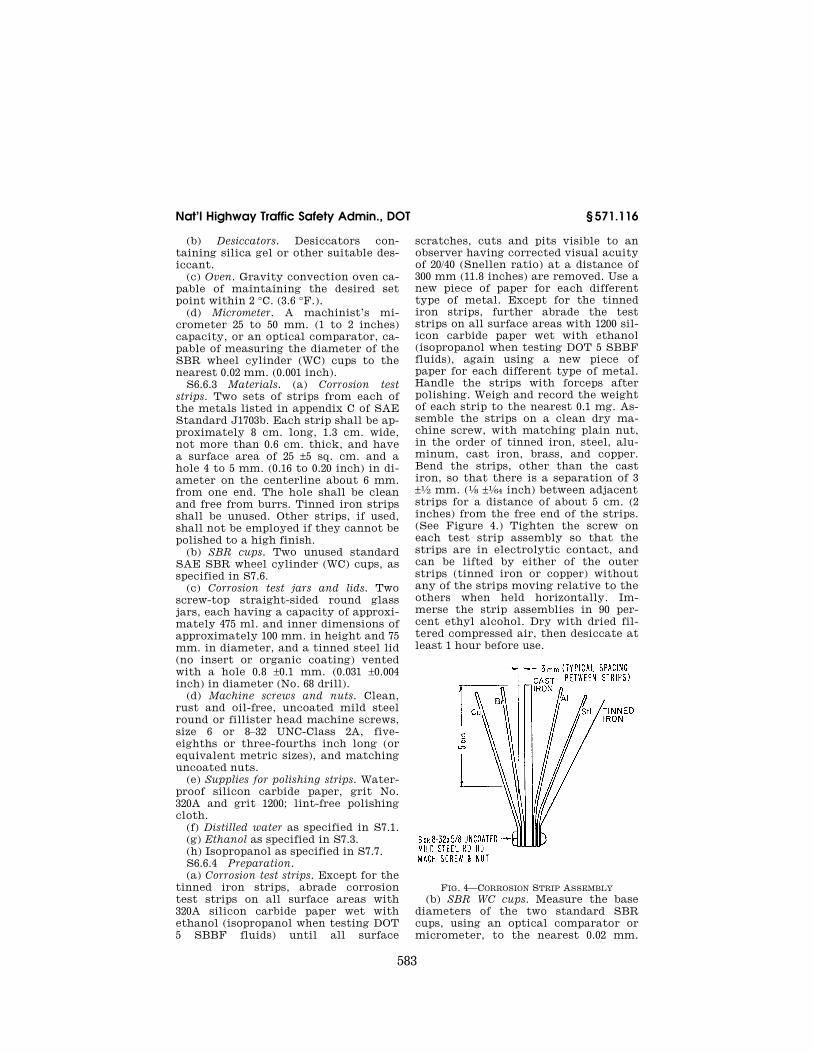
scratches, cuts and pits visible to an observer having corrected visual acuity of 20/40 (Snellen ratio) at a distance of 300 mm (11.8 inches) are removed. Use a new piece of paper for each different type of metal. Except for the tinned iron strips, further abrade the test strips on all surface areas with 1200 sil-icon carbide paper wet with ethanol (isopropanol when testing DOT 5 SBBF fluids), again using a new piece of paper for each different type of metal. Handle the strips with forceps after polishing. Weigh and record the weight of each strip to the nearest 0.1 mg. As-semble the strips on a clean dry ma-chine screw, with matching plain nut, in the order of tinned iron, steel, alu-minum, cast iron, brass, and copper. Bend the strips, other than the cast iron, so that there is a separation of 3 ±1⁄2 mm. (1⁄8 ±1⁄64 inch) between adjacent strips for a distance of about 5 cm. (2 inches) from the free end of the strips. (See Figure 4.) Tighten the screw on each test strip assembly so that the strips are in electrolytic contact, and can be lifted by either of the outer strips (tinned iron or copper) without any of the strips moving relative to the others when held horizontally. Im-merse the strip assemblies in 90 per-cent ethyl alcohol. Dry with dried fil-tered compressed air, then desiccate at least 1 hour before use.
FIG. 4—CORROSION STRIP ASSEMBLY (b) SBR WC cups. Measure the base
diameters of the two standard SBR cups, using an optical comparator or micrometer, to the nearest 0.02 mm.
VerDate Mar<15>2010 18:42 Dec 22, 2011 Jkt 223219 PO 00000 Frm 00593 Fmt 8010 Sfmt 8010 Q:\49\X49\223219.XXX ofr150 PsN: PC150 EC
01A
U91
.046
584
49 CFR Ch. V (10–1–11 Edition) § 571.116
(0.001 inch) along the centerline of the SAE and rubber-type identifications and at right angles to this centerline. Take the measurements at least 0.4 mm. (0.015 inch) above the bottom edge and parallel to the base of the cup. Dis-card any cup if the two measured diam-eters differ by more than 0.08 mm. (0.003 inch). Average the two readings on each cup. Determine the hardness of the cups according to S7.4.
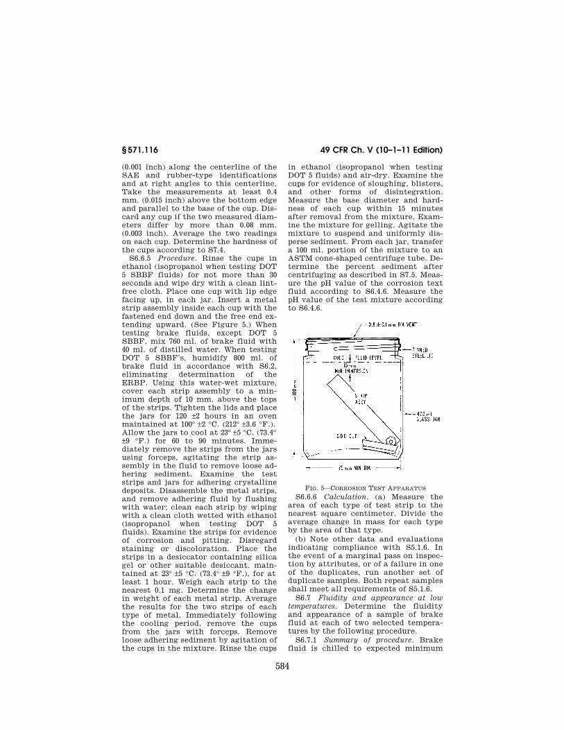
S6.6.5 Procedure. Rinse the cups in ethanol (isopropanol when testing DOT 5 SBBF fluids) for not more than 30 seconds and wipe dry with a clean lint- free cloth. Place one cup with lip edge facing up, in each jar. Insert a metal strip assembly inside each cup with the fastened end down and the free end ex-tending upward. (See Figure 5.) When testing brake fluids, except DOT 5 SBBF, mix 760 ml. of brake fluid with 40 ml. of distilled water. When testing DOT 5 SBBF’s, humidify 800 ml. of brake fluid in accordance with S6.2, eliminating determination of the ERBP. Using this water-wet mixture, cover each strip assembly to a min-imum depth of 10 mm. above the tops of the strips. Tighten the lids and place the jars for 120 ±2 hours in an oven maintained at 100° ±2 °C. (212° ±3.6 °F.). Allow the jars to cool at 23° ±5 °C. (73.4° ±9 °F.) for 60 to 90 minutes. Imme-diately remove the strips from the jars using forceps, agitating the strip as-sembly in the fluid to remove loose ad-hering sediment. Examine the test strips and jars for adhering crystalline deposits. Disassemble the metal strips, and remove adhering fluid by flushing with water; clean each strip by wiping with a clean cloth wetted with ethanol (isopropanol when testing DOT 5 fluids). Examine the strips for evidence of corrosion and pitting. Disregard staining or discoloration. Place the strips in a desiccator containing silica gel or other suitable desiccant, main-tained at 23° ±5 °C. (73.4° ±9 °F.), for at least 1 hour. Weigh each strip to the nearest 0.1 mg. Determine the change in weight of each metal strip. Average the results for the two strips of each type of metal. Immediately following the cooling period, remove the cups from the jars with forceps. Remove loose adhering sediment by agitation of the cups in the mixture. Rinse the cups
in ethanol (isopropanol when testing DOT 5 fluids) and air-dry. Examine the cups for evidence of sloughing, blisters, and other forms of disintegration. Measure the base diameter and hard-ness of each cup within 15 minutes after removal from the mixture. Exam-ine the mixture for gelling. Agitate the mixture to suspend and uniformly dis-perse sediment. From each jar, transfer a 100 ml. portion of the mixture to an ASTM cone-shaped centrifuge tube. De-termine the percent sediment after centrifuging as described in S7.5. Meas-ure the pH value of the corrosion text fluid according to S6.4.6. Measure the pH value of the test mixture according to S6.4.6.
FIG. 5—CORROSION TEST APPARATUS S6.6.6 Calculation. (a) Measure the
area of each type of test strip to the nearest square centimeter. Divide the average change in mass for each type by the area of that type.
(b) Note other data and evaluations indicating compliance with S5.1.6. In the event of a marginal pass on inspec-tion by attributes, or of a failure in one of the duplicates, run another set of duplicate samples. Both repeat samples shall meet all requirements of S5.1.6.
S6.7 Fluidity and appearance at low temperatures. Determine the fluidity and appearance of a sample of brake fluid at each of two selected tempera-tures by the following procedure.
S6.7.1 Summary of procedure. Brake fluid is chilled to expected minimum
VerDate Mar<15>2010 18:42 Dec 22, 2011 Jkt 223219 PO 00000 Frm 00594 Fmt 8010 Sfmt 8010 Q:\49\X49\223219.XXX ofr150 PsN: PC150 EC
01A
U91
.047
585
Nat’l Highway Traffic Safety Admin., DOT § 571.116
exposure temperatures and observed for clarity, gellation, sediment, separa-tion of components, excessive viscosity or thixotropy.
S6.7.2 Apparatus. (a) Oil sample bot-tle. Two clear flint glass 4–ounce bot-tles made especially for sampling oil and other liquids, with a capacity of approximately 125 ml., an outside di-ameter of 37 ±0.05 mm. and an overall height of 165 ±2.5 mm.
(b) Cold chamber. An air bath cold chamber capable of maintaining stor-age temperatures down to minus 55 °C. (minus 67 °F.) with an accuracy of ±2 °C. (3.6 °F.).
(c) Timing device. A timing device in accordance with S6.3.2(e).
S6.7.3 Procedure. (a) Place 100 ±1 ml. of brake fluid at room temperature in an oil sample bottle. Stopper the bottle with an unused cork and place in the cold chamber at the higher storage temperature specified in Table II (S5.1.7(c)). After 144 ±4 hours remove the bottle from the chamber, quickly wipe it with a clean, lint-free cloth, saturated with ethanol (isopropanol when testing DOT 5 fluids) or acetone. Examine the fluid for evidence of sludging, sedimentation, crystalliza-tion, or stratification. Invert the bottle and determine the number of seconds required for the air bubble to travel to the top of the fluid. Let sample warm to room temperature and examine.
(b) Repeat S6.7.3(a), substituting the lower cold chamber temperature speci-fied in Table II, and a storage period of 6 hours ±12 minutes.
NOTE: Test specimens from either storage temperature may be used for the other only after warming up to room temperature.
S6.8 [Reserved] S6.9 Water tolerance. Evaluate the
water tolerance characteristics of a brake fluid by running one test speci-men according to the following proce-dure.
S6.9.1 Summary of the procedure. Brake fluid, except DOT 5 SBBF, is
diluted with 3.5 percent water (DOT 5 SBBF is humidified), then stored at minus 40 °C. (minus 40 °F.) for 120 hours. The cold, water-wet fluid is first examined for clarity, stratification, and sedimentation, then placed in an oven at 60 °C. (140 °F.) for 24 hours. On removal, it is again examined for strat-
ification, and the volume percent of sediment determined by centrifuging.
S6.9.2 Apparatus. (a) Centrifuge tube. See S7.5.1(a). (b) Centrifuge. See S7.5.1(b). (c) Cold chamber. See S6.7.2(b). (d) Oven. Gravity or forced convec-
tion oven. (e) Timing device. See S6.3.2(e). S6.9.3 Procedure. (a) At low temperature. Humidify 100
±1 ml. of DOT 5 SBBF brake fluid in ac-cordance with S6.2 eliminating deter-mination of the ERBP. When testing brake fluids except DOT 5 SBBF, mix 3.5 ±0.1 ml. of distilled water with 100 ±1 ml. of the brake fluid; pour into a cen-trifuge tube. Stopper the tube with a clean cork and place in the cold cham-ber maintained at minus 40 ±2 °C. (minus 40 ±3.6 °F.). After 120 hours ±2 hours remove the tube, quickly wipe with clean lint-free cloth saturated with ethanol or acetone and examine the fluid for evidence of sludging, sedi-mentation, crystallization, or strati-fication. Invert the tube and determine the number of seconds required for the air bubble to travel to the top of the fluid. (The air bubble is considered to have reached the top of the fluid when the top of the bubble reaches the 2 ml. graduation of the centrifuge tube.) If the wet fluid has become cloudy, warm to 23 ±5 °C. (73.4 ±9 °F.) and note appear-ance and fluidity.
(b) At 60 °C. (140 °F.). Place tube and brake fluid from S6.9.3(a) in an oven maintained at 60° ±2 °C. (140° ±3.6 °F.) for 24 ±2 hours. Remove the tube and immediately examine the contents for evidence of stratification. Determine the percent sediment by centrifuging as described in S7.5.
S6.10 Compatibility. The compat-ibility of a brake fluid with other brake fluids shall be evaluated by run-ning one test sample according to the following procedure.
S6.10.1 Summary of the procedure. Brake fluid is mixed with an equal
volume of SAE RM–66–04 Compatibility Fluid, then tested in the same way as for water tolerance (S6.9) except that the bubble flow time is not measured. This test is an indication of the com-patibility of the test fluid with other motor vehicle brake fluids at both high and low temperatures.
VerDate Mar<15>2010 18:42 Dec 22, 2011 Jkt 223219 PO 00000 Frm 00595 Fmt 8010 Sfmt 8010 Q:\49\X49\223219.XXX ofr150 PsN: PC150
586
49 CFR Ch. V (10–1–11 Edition) § 571.116
S6.10.2 Apparatus and materials. (a) Centrifuge tube. See S7.5.1(a). (b) Centrifuge. See S7.5.1(b). (c) Cold Chamber. See S6.7.2(b) (d) Oven. See S6.9.2(d) (e) SAE RM–66–04 Compatibility Fluid.
As described in appendix B of SAE Standard J1703 JAN 1995 ‘‘Motor Vehi-cle Brake Fluid.’’ (SAE RM–66–03 Com-patibility Fluid as described in appen-dix A of SAE Standard J1703 NOV83, ‘‘Motor Vehicle Brake Fluid,’’ Novem-ber 1983, may be used in place of SAE RM–66–04 until January 1, 1995.)
S6.10.3 Procedure. (a) At low temperature. Mix 50 ±0.5 mL of brake fluid with 50
±0.5 mL of SAE RM–66–04 Compatibility Fluid. Pour this mixture into a cen-trifuge tube and stopper with a clean dry cork. Place tube in the cold cham-ber maintained at minus 40° ±2 °C. (minus 40° ±4 °F). After 24 ±2 hours, re-move tube, quickly wipe with a clean lint-free cloth saturated with ethanol (isopropanol when testing DOT 5 fluids) or acetone. Examine the test specimen for evidence of slugging, sedimenta-tion, or crystallization. Test fluids, ex-cept DOT 5 SBBF, shall be examined for stratification.
S6.11 Resistance to oxidation. The stability of a brake fluid under oxidative conditions shall be evaluated by running duplicate samples accord-ing to the following procedure.
S6.11.1 Summary of procedure. Brake fluids, except DOT 5 SBBF, are
activated with a mixture of approxi-mately 0.2 percent benzoyl peroxide and 5 percent water. DOT 5 SBBF is hu-midified in accordance with S6.2 elimi-nating determination of the ERBP, and then approximately 0.2 percent benzoyl peroxide is added. A corrosion test strip assembly consisting of cast iron and an aluminum strip separated by tinfoil squares at each end is then rest-ed on a piece of SBR WC cup positioned so that the test strip is half immersed in the fluid and oven aged at 70 °C. (158 °F.) for 168 hours. At the end of this pe-riod, the metal strips are examined for pitting, etching, and loss of mass.
S6.11.2 Equipment. (a) Balance. See S6.6.2(a). (b) Desiccators. See S6.6.2(b). (c) Oven. See S6.6.2(c).
(d) Three glass test tubes approxi-mately 22 mm. outside diameter by 175 mm. in length.
S6.11.3 Reagents and materials. (a) Benzoyl peroxide, reagent grade, 96
percent. (Benzoyl peroxide that is brownish, or dusty, or has less than 90 percent purity, must be discarded.) Re-agent strength may be evaluated by ASTM E298–68, ‘‘Standard Methods for Assay of Organic Peroxides.’’
(b) Corrosion test strips. Two sets of cast iron and aluminum metal test strips as described in appendix C of SAE Standard J1703b.
(c) Tinfoil. Four unused pieces of tin-foil approximately 12 mm. (1⁄2 inch) square and between 0.02 and 0.06 mm. (0.0008 and 0.0024 inch) in thickness. The foil shall be at least 99.9 percent tin and contain not more than 0.025 percent lead.
(d) SBR cups. Two unused, approxi-mately one-eighth sections of a stand-ard SAE SBR WC cup (as described in S7.6).
(e) Machine screw and nut. Two clean oil-free, No. 6 or 8–32×3⁄8¥ or 1⁄2–inch long (or equivalent metric size), round or fillister head, uncoated mild steel machine screws, with matching plain nuts.
S6.11.4 Preparation. (a) Corrosion test strips. Prepare two
sets of aluminum and cast iron test strips according to S6.6.4(a) except for assembly. Weigh each strip to the near-est 0.1 mg. and assemble a strip of each metal on a machine screw, separating the strips at each end with a piece of tinfoil. Tighten the nut enough to hold both pieces of foil firmly in place.
(b) Test mixture.Place 30 ±1 ml. of the brake fluid under test in a 22 by 175 mm. test tube. For all fluids except DOT 5 SBBF, add 0.060 ±.002 grams of benzoyl peroxide, and 1.50 ±0.05 ml. of distilled water. For DOT 5 SBBF, use test fluid humidified in accordance with S6.2, and add only the benzoyl peroxide. Stopper the tube loosely with a clean dry cork, shake, and place in an oven for 2 hours at 70° ±2 °C. (158° ±3.6 °F.). Shake every 15 minutes to effect solution of the peroxide, but do not wet cork. Remove the tube from the oven and allow to cool to 23° ±5 °C. (73.4° ±9
VerDate Mar<15>2010 18:42 Dec 22, 2011 Jkt 223219 PO 00000 Frm 00596 Fmt 8010 Sfmt 8010 Q:\49\X49\223219.XXX ofr150 PsN: PC150
587
Nat’l Highway Traffic Safety Admin., DOT § 571.116
°F.) Begin testing according to para-graph S6.11.5 not later than 24 hours after removal of tube from oven.
S6.11.5 Procedure. Place a one-eighth SBR cup section in the bottom of each tube. Add 10 ml. of prepared test mix-ture to each test tube. Place a metal- strip assembly in each, the end of the strip without the screw resting on the rubber, and the solution covering about one-half the length of the strips. Stop-per the tubes with clean dry corks and store upright for 70 ±2 hours at 23° ±5 °C. (73.4° ±9 °F.). Loosen the corks and place the tubes for 168 ±2 hours in an oven maintained at 70° ±2 °C. (158° ±3.6 °F.). Afterwards remove and dis-assemble strips. Examine the strips and note any gum deposits. Wipe the strips with a clean cloth wet with eth-anol (isopropanol when testing DOT 5 fluids) and note any pitting, etching or roughening of surface disregarding stain or discoloration. Place the strips in a desiccator over silica gel or other suitable desiccant, at 23° ±5 °C. (73.4° ±9 °F.) for at least 1 hour. Again weigh each strip to the nearest 0.1 mg.
S6.11.6 Calculation. Determine corro-sion loss by dividing the change in mass of each metal strip by the total surface area of each strip measured in square millimeters (mm2), to the near-est square millimeter (mm2). Average the results for the two strips of each type of metal, rounding to the nearest 0.05 mg. per 100 square millimeter (mm2). If only one of the duplicates fails for any reason, run a second set of duplicate samples. Both repeat samples shall meet all requirements of S5.1.11.
S6.12 Effect on SBR cups. The effects of a brake fluid in swelling, softening, and otherwise affecting standard SBR WC cups shall be evaluated by the fol-lowing procedure.
S6.12.1 Summary of the procedure. Four standard SAE SBR WC cups are measured and their hardnesses deter-mined. The cups, two to a jar, are im-mersed in the test brake fluid. One jar is heated for 70 hours at 70 °C. (158 °F), and the other for 70 hours at 120 °C (248 °F). Afterwards, the cups are washed, examined for disintegration, remeas-ured and their hardnesses redeter-mined.
S6.12.2 Equipment and supplies. (a) Oven. See S6.6.2(c).
(b) Glass jars and lids. Two screw-top, straight-sided round glass jars, each having a capacity of approximately 250 ml. and inner dimensions of approxi-mately 125 mm. in height and 50 mm. in diameter, and a tinned steel lid (no insert or organic coating).
(c) SBR cups. See S7.6. S6.12.3 Preparation. Measure the
base diameters of the SBR cups as de-scribed in S6.6.4(b), and the hardness of each as described in S7.4.
S6.12.4 Procedure. Wash the cups in 90 percent ethanol (isopropanol when testing DOT 5 fluids) (see S7.3), for not longer than 30 seconds and quickly dry with a clean, lint-free cloth. Using for-ceps, place two cups into each of the two jars; add 75 ml. of brake fluid to each jar and cap tightly. Place one jar in an oven held at 70° ±2 °C. (158 ±3.6 °F.) for 70 ±2 hours. Place the other jar in an oven held at 120° ±2 °C. (248° ±3.6 °F.) for 70 ±2 hours. Allow each jar to cool for 60 to 90 minutes at 23° ±5 °C. (73.4° ±9 °F.). Remove cups, wash with ethanol (isopropanol when testing DOT 5 fluids) for not longer than 30 seconds, and quickly dry. Examine the cups for disintegration as evidenced by sticki-ness, blisters, or sloughing. Measure the base diameter and hardness of each cup within 15 minutes after removal from the fluid.
S6.12.5 Calculation. (a) Calculate the change in base diameter for each cup. If the two values, at each temperature, do not differ by more than 0.10 mm. (0.004 inch) average them to the nearest 0.02 mm. (0.001 inch). If the two values differ by more than 0.10 mm., repeat the test at the appropriate tempera-ture and average the four values as the change in base diameter.
(b) Calculate the change in hardness for each cup. The average of the two values for each pair is the change in hardness.
(c) Note disintegration as evidenced by stickiness, blisters, or sloughing.
S6.13 Stroking properties. Evaluate the lubricating properties, component compatibility, resistance to leakage, and related qualities of a brake fluid by running one sample according to the following procedures.
S6.13.1 Summary of the procedure. Brake fluid is stroked under controlled conditions at an elevated temperature
VerDate Mar<15>2010 18:42 Dec 22, 2011 Jkt 223219 PO 00000 Frm 00597 Fmt 8010 Sfmt 8010 Q:\49\X49\223219.XXX ofr150 PsN: PC150
588
49 CFR Ch. V (10–1–11 Edition) § 571.116
in a simulated motor vehicle hydraulic braking system consisting of three slave wheel cylinders and an actuating master cylinder connected by steel tub-ing. Referee standard parts are used. All parts are carefully cleaned, exam-ined, and certain measurements made immediately prior to assembly for test. During the test, temperature, rate of pressure rise, maximum pressure, and rate of stroking are specified and con-trolled. The system is examined peri-odically during stroking to assure that excessive leakage of fluid is not occur-ring. Afterwards, the system is torn down. Metal parts and SBR cups are examined and remeasured. The brake fluid and any resultant sludge and de-bris are collected, examined, and test-ed.
S6.13.2 Apparatus and equipment. Either the drum and shoe type of
stroking apparatus (see Figure 1 of SAE Standard J1703b) except using only three sets of drum and shoe as-semblies, or the stroking fixture type apparatus as shown in Figure 2 of SAE J1703Nov83, with the components ar-ranged as shown in Figure 1 of SAE J1703Nov83. The following components are required.
(a) Brake assemblies. With the drum and shoe apparatus: three drum and shoe assembly units (SAE RM–29a) con-sisting of three forward brake shoes and three reverse brake shoes with lin-ings and three front wheel brake drum assemblies with assembly component parts. With stroking fixture type appa-ratus: three fixture units including ap-propriate adapter mounting plates to hold brake wheel cylinder assemblies.
(b) Braking pressure actuation mecha-nism. An actuating mechanism for ap-plying a force to the master cylinder pushrod without side thrust. The amount of force applied by the actu-ating mechanism shall be adjustable and capable of applying sufficient thrust to the master cylinder to create a pressure of at least 6895 kPa (1,000 p.s.i.) in the simulated brake system. A hydraulic gage or pressure recorder, having a range of at least 0 to 6895 kPa (0 to 1,000 p.s.i), shall be installed be-tween the master cylinder and the brake assemblies and shall be provided with a shutoff valve and with a bleed-ing valve for removing air from the
connecting tubing. The actuating mechanism shall be designed to permit adjustable stroking rates of approxi-mately 1,000 strokes per hour. Use a mechanical or electrical counter to record the total number of strokes.
(c) Heated air bath cabinet. An insu-lated cabinet or oven having sufficient capacity to house the three mounted brake assemblies or stroking fixture assemblies, master cylinder, and nec-essary connections. A thermostatically controlled heating system is required to maintain a temperature of 70° ±5 °C (158° ±9 °F) or 120° ±5 °C (248° ±9 °F). Heaters shall be shielded to prevent di-rect radiation to wheel or master cyl-inder.
(d) Master cylinder (MC) assembly (SAE RM–15a). One cast iron housing hydrau-lic brake system cylinder having a di-ameter of approximately 28 mm. (11⁄8 inch) and fitted for a filler cap and standpipe (see S6.13.2(e)). The MC pis-ton shall be made from SAE CA360 copperbase alloy (half hard). A new MC assembly is required for each test.
(e) Filler cap and standpipe. MC filler cap provided with a glass or uncoated steel standpipe. Standpipe must pro-vide adequate volume for thermal ex-pansion, yet permit measurement and adjustment of the fluid level in the sys-tem to ±3 ml. Cap and standpipe may be cleaned and reused.
(f) Wheel cylinder (WC) assemblies (SAE RM–14a). Three unused cast iron hous-ing straight bore hydraulic brake WC assemblies having diameters of ap-proximately 28 mm (11⁄8 inch) for each test. Pistons shall be made from unanodized SAE AA 2024 aluminum alloy.
(g) Micrometer. Same as S6.6.2(d). S6.13.3 Materials. (a) Standard SBR brake cups. Six
standard SAE SBR wheel cylinder test cups, one primary MC test cup, and one secondary MC test cup, all as described in S7.6, for each test.
(b) Steel tubing. Double wall steel tub-ing meeting SAE specification J527. A complete replacement of tubing is es-sential when visual inspection indi-cates any corrosion or deposits on inner surface of tubing. Tubing from master cylinder to one wheel cylinder
VerDate Mar<15>2010 18:42 Dec 22, 2011 Jkt 223219 PO 00000 Frm 00598 Fmt 8010 Sfmt 8010 Q:\49\X49\223219.XXX ofr150 PsN: PC150
589
Nat’l Highway Traffic Safety Admin., DOT § 571.116
shall be replaced for each test (min-imum length .9 m.) Uniformity in tub-ing size is required between master cyl-inder and wheel cylinder. The standard master cylinder has two outlets for tubing, both of which must be used.
S6.13.4 Preparation of test apparatus. (a) Wheel cylinder assemblies. Use un-
used wheel cylinder assemblies. Dis-assemble cylinders and discard cups. Clean all metal parts with ethanol (isopropanol when testing DOT 5 fluids). Inspect the working surfaces of all metal parts for scoring, galling, or pitting and cylinder bore roughness, and discard all defective parts. Remove any stains on cylinder walls with cro-cus cloth and ethanol (isopropanol when testing DOT 5 fluids). If stains cannot be removed, discard the cyl-inder. Measure the internal diameter of each cylinder at a location approxi-mately 19 mm. (0.75 inch) from each end of the cylinder bore, taking meas-urements in line with the hydraulic inlet opening and at right angles to this centerline. Discard the cylinder if any of these four readings exceeds the maximum or minimum limits of 28.66 to 28.60 mm. (1.128 to 1.126 inch). Meas-ure the outside diameter of each piston at two points approximately 90° apart. Discard any piston if either reading ex-ceeds the maximum or minimum limits of 28.55 to 28.52 mm. (1.124 to 1.123 inch). Select parts to insure that the clear-ance between each piston and mating cylinder is within 0.08 to 0.13 mm. (0.003 to 0.005 inch). Use unused SBR cups. To remove dirt and debris, rinse the cups in 90 percent ethyl alcohol for not more than 30 seconds and wipe dry with a clean lint-free cloth. Discard any cups showing defects such as cuts, molding flaws, or blisters. Measure the lip and base diameters of all cups with an opti-cal comparator or micrometer to the nearest 0.02 mm. (0.001 inch) along the centerline of the SAE and rubber-type identifications and at right angles to this centerline. Determine base diame-ter measurements at least 0.4 mm. (0.015 inch) above the bottom edge and parallel to the base of the cup. Discard any cup if the two measured lip or base diameters differ by more than 0.08 mm. (0.003 inch). Average the lip and base diameters of each cup. Determine the hardness of all cups according to S7.4.
Dip the rubber and metal parts of wheel cylinders, except housing and rubber boots, in the fluid to be tested and install them in accordance with the manufacturer’s instructions. Manu-ally stroke the cylinders to insure that they operate easily. Install cylinders in the simulated brake system.
(b) Master cylinder assembly. Use an unused master cylinder and unused standard SBR primary and secondary MC cups which have been inspected, measured and cleaned in the manner specified in S6.13.4(a), omitting hard-ness of the secondary MC cup. How-ever, prior to determining the lip and base diameters of the secondary cup, dip the cup in test brake fluid, assem-ble on the MC piston, and maintain the assembly in a vertical position at 23° ±5 °C. (73.4° ±9 °F.) for at least 12 hours. Inspect the relief and supply ports of the master cylinder; discard the cyl-inder if ports have burrs or wire edges. Measure the internal diameter of the cylinder at two locations (approxi-mately midway between the relief and supply ports and approximately 19 mm. (0.75 inch) beyond the relief port to-ward the bottom or discharge end of the bore), taking measurements at each location on the vertical and hori-zontal centerline of the bore. Discard the cylinder if any reading exceeds the maximum or minimum limits of 28.65 to 28.57 mm. (1.128 to 1.125 inch). Meas-ure the outside diameter of each end of the master cylinder piston at two points approximately 90° apart. Discard the piston if any of these four readings exceed the maximum or minimum lim-its of 28.55 to 28.52 mm. (1.124 to 1.123 inch). Dip the rubber and metal parts of the master cylinder, except the housing and push rod-boot assembly, in the brake fluid and install in accord-ance with manufacturer’s instructions. Manually stroke the master cylinder to insure that it operates easily. Install the master cylinder in the simulated brake system.
(c) Assembly and adjustment of test ap-paratus.
(1) When using a shoe and drum type apparatus, adjust the brake shoe toe clearances to 1.0 ±0.1 mm (0.040 ±0.004 inch). Fill the system with brake fluid, bleeding all wheel cylinders and the pressure gage to remove entrapped air.
VerDate Mar<15>2010 18:42 Dec 22, 2011 Jkt 223219 PO 00000 Frm 00599 Fmt 8010 Sfmt 8010 Q:\49\X49\223219.XXX ofr150 PsN: PC150
590
49 CFR Ch. V (10–1–11 Edition) § 571.116
Operate the actuator manually to apply a pressure greater than the re-quired operating pressure and inspect the system for leaks. Adjust the actu-ator and/or pressure relief valve to ob-tain a pressure of 6895 kPa ±345 kPa (1,000 ±50 p.s.i.). A smooth pressure stroke pattern is required when using a shoe and drum type apparatus. The pressure is relatively low during the first part of the stroke and then builds up smoothly to the maximum stroking pressure at the end of the stroke, to permit the primary cup to pass the compensating hole at a relatively low pressure. Using stroking fixtures, ad-just the actuator and/or pressure relief valve to obtain a pressure of 6895 kPa ±345 kPa (1,000 ±50 p.s.i.).
(2) Adjust the stroking rate to 1,000 ±100 strokes per hour. Record the fluid level in the master cylinder standpipe.
S6.13.5 Procedure. Operate the sys-tem for 16,000 ±1,000 cycles at 23° ±5 °C. (73.4° ±9 °F.). Repair any leakage, read-just the brake shoe clearances, and add fluid to the master cylinder standpipe to bring to the level originally re-corded, if necessary. Start the test again and raise the temperature of the cabinet within 6 ±2 hours to 120° ±5 °C. (248° ±9 °F.). During the test observe op-eration of wheel cylinders for improper functioning and record the amount of fluid required to replenish any loss, at intervals of 24,000 strokes. Stop the test at the end of 85,000 total recorded strokes. These totals shall include the number of strokes during operation at 23° ±5 °C. (73.4° ±9 °F.) and the number of strokes required to bring the system to the operating temperature. Allow equipment to cool to room tempera-ture. Examine the wheel cylinders for leakage. Stroke the assembly an addi-tional 100 strokes, examine wheel cyl-inders for leakage and record volume loss of fluid. Within 16 hours after stop-ping the test, remove the master and wheel cylinders from the system, re-taining the fluid in the cylinders by immediately capping or plugging the ports. Disassemble the cylinders, col-lecting the fluid from the master cyl-inder and wheel cylinders in a glass jar. When collecting the stroked fluid, re-move all residue which has deposited on rubber and metal internal parts by rinsing and agitating such parts in the
stroked fluid and using a soft brush to assure that all loose adhering sediment is collected. Clean SBR cups in ethanol (isopropanol when testing DOT 5 fluids) and dry. Inspect the cups for sticki-ness, scuffing, blistering, cracking, chipping, and change in shape from original appearance. Within 1 hour after disassembly, measure the lip and base diameters of each cylinder cup by the procedures specified in S6.13.4 (a) and (b) with the exception that lip or base diameters of cups may now differ by more than 0.08 mm. (0.003 inch). De-termine the hardness of each cup ac-cording to S7.4. Note any sludge or gel present in the test fluid. Within 1 hour after draining the cylinders, agitate the fluid in a glass jar to suspend and uniformly disperse sediment and trans-fer a 100 ml. portion of this fluid to a centrifuge tube and determine percent sediment as described in S7.5. Allow the tube and fluid to stand for 24 hours, recentrifuge and record any additional sediment recovered. Inspect cylinder parts, note any gumming or any pit-ting on pistons and cylinder walls. Dis-regard staining or discoloration. Rub any deposits adhering to cylinder walls with a clean soft cloth wetted with eth-anol (isopropanol when testing DOT 5 fluids) to determine abrasiveness and removability. Clean cylinder parts in ethanol (isopropanol when testing DOT 5 fluids) and dry. Measure and record diameters of pistons and cylinders ac-cording to S6.13.4(a) and (b). Repeat the test if mechanical failure occurs that may affect the evaluation of the brake fluid.
S6.13.6 Calculation. (a) Calculate the changes in diameters of cylinders and pistons (see S5.1.13(b)).
(b) Calculate the average decrease in hardness of the seven cups tested, as well as the individual values (see S5.1.13(c)).
(c) Calculate the increases in base di-ameters of the eight cups (see S5.1.13(e)).
(d) Calculate the lip diameter inter-ference set for each of the eight cups by the following formula and average the eight values (see S5.1.13(f)).
[(D1¥D2)/(D1¥D3)]×100=percentage Lip Diameter Interference Set
where:
VerDate Mar<15>2010 18:42 Dec 22, 2011 Jkt 223219 PO 00000 Frm 00600 Fmt 8010 Sfmt 8003 Q:\49\X49\223219.XXX ofr150 PsN: PC150
591
Nat’l Highway Traffic Safety Admin., DOT § 571.116
D1=Original lip diameter. D2=Final lip diameter. D3=Original cylinder bore diameter.
S6.14 Container information. Each con-tainer with information marked di-rectly on the container surface or on a label (labels) affixed to the container pursuant to S5.2.2.2 or S5.2.2.3 is sub-jected to the following procedure:
(a) If the container has a label affixed to it, make a single vertical cut all the way through the label with the con-tainer in the vertical position.
(b) Immerse the container in the same brake fluid or hydraulic system mineral oil contained therein for 15 minutes at room temperature (23 ±5 °C; 73.4 ±9 °F).
(c) Within 5 minutes after removing the container from the fluid or oil, re-move excess liquid from the surface of the container by wiping with a clean dry cloth.
S7. Auxiliary test methods and reagent standards.
S7.1 Distilled water. Nonreferee rea-gent water as specified in ASTM D1193– 70, ‘‘Standard Specifications for Rea-gent Water,’’ or water of equal purity.
S7.2 Water content of motor vehicle brake fluids. Use analytical methods based on ASTM D1123–59, ‘‘Standard Method of Test for Water in Con-centrated Engine Antifreezes by the Io-dine Reagent Method,’’ for determining the water content of brake fluids, or other methods of analysis yielding comparable results. To be acceptable for use, such other method must meas-ure the weight of water added to sam-ples of the SAE RM–66–04 and TEGME Compatibility Fluids within ±15 per-cent of the water added for additions up to 0.8 percent by weight, and within ±5 percent of the water added for addi-tions greater than 0.8 percent by weight. The SAE RM–66–04 Compat-ibility Fluid used to prepare the sam-ples must have an original ERBP of not less than 205 °C (401 °F) when tested in accordance with S6.1. The SAE TEGME fluid used to prepare the samples must have an original ERBP of not less than 240 °C (464 °F) when tested in accord-ance with S6.1.
S7.3 Ethanol. 95 percent (190 proof) ethyl alcohol, USP or ACS, or Formula 3–A Specially Denatured Alcohol of the same concentration (as specified at 27
CFR 21.35). For pretest washings of equipment, use approximately 90 per-cent ethyl alcohol, obtained by adding 5 parts of distilled water to 95 parts of ethanol.
S7.4 Measuring the hardness of SBR brake cups. Hardness measurements on SBR wheel cylinder cups and master cylinder primary cups shall be made by using the following apparatus and the following procedure.
S7.4.1 Apparatus. (a) Anvil. A rubber anvil having a flat
circular top 20 ±1 mm. (13⁄16 ±1⁄16 inch) in diameter, a thickness of at least 9 mm. (3⁄8 inch) and a hardness within 5 IRHDs of the SBR test cup.
(b) Hardness tester. A hardness tester meeting the requirements for the standard instrument as described in ASTM D1415–68, ‘‘Standard Method of Test for International Hardness of Vul-canized Natural and Synthetic Rub-bers,’’ and graduated directly in IRHD units.
S7.4.2 Procedure. Make hardness measurements at 23° ±2 °C. (73.4° ±4 °F.). Equilibrate the tester and anvils at this temperature prior to use. Center brake cups lip side down on an anvil of appropriate hardness. Following the manufacturer’s operating instructions for the hardness tester, make one measurement at each of four points 6 mm from the center of the cup and spaced 90° apart. Average the four val-ues, and round off to the nearest IRHD.
S7.5 Sediment by centrifuging. The amount of sediment in the test fluid shall be determined by the following procedure.
S7.5.1 Apparatus. (a) Centrifuge tube. Cone-shaped cen-
trifuge tubes conforming to the dimen-sions given in Figure 6, and made of thoroughly annealed glass. The gradua-tions shall be numbered as shown in Figure 6, and shall be clear and dis-tinct. Scale-error tolerances and small-est graduations between various cali-bration marks are given in Table V and apply to calibrations made with air- free water at 20 °C. (68 °F.).
VerDate Mar<15>2010 18:42 Dec 22, 2011 Jkt 223219 PO 00000 Frm 00601 Fmt 8010 Sfmt 8010 Q:\49\X49\223219.XXX ofr150 PsN: PC150
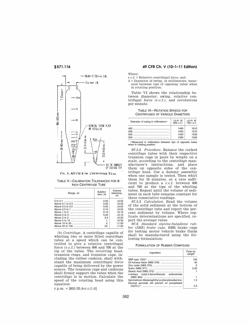
592
49 CFR Ch. V (10–1–11 Edition) § 571.116
TABLE V—CALIBRATION TOLERANCES FOR 8- INCH CENTRIFUGE TUBE
Range, ml Subdivi-sion, ml
Volume tolerance,
ml
0 to 0.1 .......................................... 0.05 ±0.02 Above 0.1 to 0.3 ............................ 0.05 ±0.03 Above 0.3 to 0.5 ............................ 0.05 ±0.05 Above 0.5 to 1 ............................... 0.10 ±0.05 Above 1 to 2 .................................. 0.10 ±0.10 Above 2 to 3 .................................. 0.20 ±0.10 Above 3 to 5 .................................. 0.5 ±0.20 Above 5 to 10 ................................ 1. ±0.50 Above 10 to 25 .............................. 5. ±1.00 Above 25 to 100 ............................ 25. ±1.00
(b) Centrifuge. A centrifuge capable of whirling two or more filled centrifuge tubes at a speed which can be con-trolled to give a relative centrifugal force (r.c.f.) between 600 and 700 at the tip of the tubes. The revolving head, trunnion rings, and trunnion cups, in-cluding the rubber cushion, shall with-stand the maximum centrifugal force capable of being delivered by the power source. The trunnion cups and cushions shall firmly support the tubes when the centrifuge is in motion. Calculate the speed of the rotating head using this equation: r.p.m. = 265[√25.4×r.c.f./d]
Where: r.c.f. = Relative centrifugal force, and d = Diameter of swing, in millimeters, meas-
ured between tips of opposing tubes when in rotating position.
Table VI shows the relationship be-tween diameter, swing, relative cen-trifugal force (r.c.f.), and revolutions per minute.
TABLE VI—ROTATION SPEEDS FOR CENTRIFUGES OF VARIOUS DIAMETERS
Diameter of swing in millimeters a r.p.m. at 600 r.c.f
r.p.m. at 700 r.c.f.
483 ..................................................... 1490 1610 508 ..................................................... 1450 1570 533 ..................................................... 1420 1530 559 ..................................................... 1390 1500
a Measured in millimeters between tips of opposite tubes when in rotating position.
S7.5.2 Procedure. Balance the corked centrifuge tubes with their respective trunnion cups in pairs by weight on a scale, according to the centrifuge man-ufacturer’s instructions, and place them on opposite sides of the cen-trifuge head. Use a dummy assembly when one sample is tested. Then whirl them for 10 minutes, at a rate suffi-cient to produce a r.c.f. between 600 and 700 at the tips of the whirling tubes. Repeat until the volume of sedi-ment in each tube remains constant for three consecutive readings.
S7.5.3 Calculation. Read the volume of the solid sediment at the bottom of the centrifuge tube and report the per-cent sediment by volume. Where rep-licate determinations are specified, re-port the average value.
S7.6 Standard styrene-butadiene rub-ber (SBR) brake cups. SBR brake cups for testing motor vehicle brake fluids shall be manufactured using the fol-lowing formulation:
FORMULATION OF RUBBER COMPOUND
Ingredient Parts by weight
SBR type 1503 a .................................................. 100 Oil furnace black (NBS 378) ............................... 40 Zinc oxide (NBS 370) .......................................... 5 Sulfur (NBS 371) ................................................. 0.25 Stearic Acid (NBS 372) ....................................... 1 n-tertiary butyl-2-benzothiazole sulfenamide
(NBS 384) ........................................................ 1 Symmetrical dibetanaphthyl-p-phenylenediamine 1.5 Dicumyl peroxide (40 percent on precipitated
CaCO3) b .......................................................... 4.5
VerDate Mar<15>2010 18:42 Dec 22, 2011 Jkt 223219 PO 00000 Frm 00602 Fmt 8010 Sfmt 8010 Q:\49\X49\223219.XXX ofr150 PsN: PC150 EC
01A
U91
.048
593
Nat’l Highway Traffic Safety Admin., DOT § 571.117
FORMULATION OF RUBBER COMPOUND— Continued
Ingredient Parts by weight
Total .......................................................... 153.25
a Philprene 1503 has been found suitable. b Use only within 90 days of manufacture and store at tem-
perature below 27 °C. (80 °F.). NOTE: The ingredients labeled (NBS) must have properties
identical with those supplied by the National Bureau of Standards.
Compounding, vulcanization, physical properties, size of the finished cups, and other details shall be as specified in appendix B of SAE J1703b. The cups shall be used in testing brake fluids ei-ther within 6 months from date of man-ufacture when stored at room tempera-ture below 30 °C. (86 °F.) or within 36 months from date of manufacture when stored at temperatures below minus 15 °C. (+5 °F.). After removal of cups from refrigeration they shall be conditioned base down on a flat surface for at least 12 hours at room temperature in order to allow cups to reach their true con-figuration before measurement.
S7.7 Isopropanol. ACS or reagent grade.
[36 FR 22902, Dec. 2, 1971]
EDITORIAL NOTE: For FEDERAL REGISTER ci-tations affecting § 571.116, see the List of CFR Sections Affected, which appears in the Finding Aids section of the printed volume and on GPO Access.
§ 571.117 Standard No. 117; Retreaded pneumatic tires.
S1. Scope. This standard specifies per-formance, labeling, and certification requirements for retreaded pneumatic passenger car tires.
S2. Purpose. The purpose of this standard is to require retreaded pneu-matic passenger car tires to meet safe-ty criteria similar to those for new pneumatic passenger car tires.
S3. Application. This standard applies to retreaded pneumatic tires for use on passenger cars manufactured after 1948.
S4. Definitions. S4.1 Casing means a used tire to
which additional tread may be at-tached for the purpose of retreading.
Retreaded means manufactured by a process in which a tread is attached to a casing.
S4.2 All terms defined in §§ 571.109 and 571.110 are used as defined therein.
S5. Requirements. S5.1 Retreaded tires. S5.1.1 Except as specified in S5.1.3,
each retreaded tire, when mounted on a test rim of the width specified for the tire’s size designation in appendix A of § 571.109 shall comply with the fol-lowing requirements of § 571.109:
(a) S4.1 (Size and construction). (b) S4.2.1 (General). (c) S4.2.2.3 (Tubeless tire resistance
to bead unseating). (d) S4.2.2.4 (Tire strength). S5.1.2 Except as specified in S5.1.3,
each retreaded tire, when mounted on a test rim of the width specified for the tire’s size designation in appendix A of § 571.109, shall comply with the require-ments of S4.2.2.2 of § 571.109, except that the tire’s section width shall not be more than 110 percent of the section width specified, and the tire’s size fac-tor shall be at least 97 percent of the size factor specified, in appendix A of § 571.109 for the tire’s size designation.
S5.1.3 Each retreaded tire shall be capable of meeting the requirements of S5.1.1 and S5.1.2 when mounted on any rim in accordance with those sections.
S5.1.4 No retreaded tire shall have a size designation, recommended max-imum load rating, or maximum per-missible inflation pressure that is greater than that originally specified on the casing pursuant to S4.3 of § 571.109, or specified for the casing in Table I.
S5.2 Casings. S5.2.1 No retreaded tire shall be
manufactured with a casing— (a) On which bead wire or cord fabric
is exposed before processing. (b) On which any cord fabric is ex-
posed during processing, except that cord fabric that is located at a splice, i.e., where two or more segments of the same ply overlap, or cord fabric that is part of the belt material, may be ex-posed but shall not be penetrated or re-moved to any extent whatsoever.
S5.2.2 No retreaded tire shall be manufactured with a casing—
(a) From which a belt or ply, or part thereof, is removed during processing; or
(b) On which a belt or ply, or part thereof, is added or replaced during processing.
VerDate Mar<15>2010 18:42 Dec 22, 2011 Jkt 223219 PO 00000 Frm 00603 Fmt 8010 Sfmt 8010 Q:\49\X49\223219.XXX ofr150 PsN: PC150