Embed Size (px)
Citation preview
FVersion 1.00
Revision ASeptember 2002
5700/5800 GPS ReceiverUser Guide
Corporate Office
Trimble Navigation LimitedEngineering and Construction Division5475 Kellenburger RoadDayton, Ohio 45424-1099U.S.A.
Copyright and Trademarks
© 2001-2002, Trimble Navigation Limited. All rights reserved.
The Globe & Triangle logo, Trimble, Configuration Toolbox, eRTK, Micro-Centred, QuickPlan, SiteNet, Trimble Geomatics Office, Trimble Survey Controller, Trimble Survey Pro, TRIMMARK, TRIMTALK, TSC1, TSCe, and Zephyr are trademarks of Trimble Navigation Limited.
Bluetooth is a trademark owned by Bluetooth SIG,
Inc. and is used by Trimble Navigation under license.
GPS Total Station is a trademark of Trimble Navigation Limited, registered in the United States Patent and Trademark Office.
All other trademarks are the property of their respective owners.
Release Notice
This is the September 2002 release (Revision A) of the 5700/5800 GPS Receiver User Guide.
The following limited warranties give you specific legal rights. You may have others, which vary from state/jurisdiction to state/jurisdiction.
Hardware Limited Warranty
Trimble warrants that this Trimble hardware product (the “Product”) shall be free from defects in materials and workmanship and will substantially conform to Trimble’s applicable published specifications for the Product for a period of one (1) year, starting from the date of delivery. The warranty set forth in this paragraph shall not apply to software/firmware products.
Software and Firmware License, Limited Warranty
This Trimble software and/or firmware product (the “Software”) is licensed and not sold. Its use is governed by the provisions of the applicable End User License Agreement (“EULA”), if any, included with the Software. In the absence of a separate EULA included with the Software providing different limited warranty terms, exclusions, and limitations, the following terms and conditions shall apply. Trimble warrants that this Trimble Software product will substantially conform to Trimble’s applicable published specifications for the Software for a period of ninety (90) days, starting from the date of delivery.
Warranty Remedies
Trimble's sole liability and your exclusive remedy under the warranties set forth above shall be, at Trimble’s option, to repair or replace any Product or Software that fails to conform to such warranty (“Nonconforming Product”), or refund the purchase price paid by you for any such Nonconforming Product, upon your return of any Nonconforming Product to Trimble in accordance with Trimble’s standard return material authorization procedures.
Warranty Exclusions and Disclaimer
These warranties shall be applied only in the event and to the extent that: (i) the Products and Software are properly and correctly installed, configured, interfaced, maintained, stored, and operated in accordance with Trimble’s relevant operator's manual and specifications, and; (ii) the Products and Software are not modified or misused. The preceding warranties shall not apply to, and Trimble shall not be responsible for defects or performance problems resulting from (i) the combination or utilization of the Product or Software with products, information, data, systems or devices not made, supplied or specified by Trimble; (ii) the operation of the Product or Software under any specification other than, or in addition to, Trimble's standard specifications for its products; (iii) the unauthorized modification or use of the Product or Software; (iv) damage caused by accident, lightning or other electrical discharge, fresh or salt water immersion or spray; or (v) normal wear and tear on consumable parts (e.g., batteries).
THE WARRANTIES ABOVE STATE TRIMBLE'S ENTIRE LIABILITY, AND YOUR EXCLUSIVE REMEDIES, RELATING TO PERFORMANCE OF THE PRODUCTS AND SOFTWARE. EXCEPT AS OTHERWISE EXPRESSLY PROVIDED HEREIN, THE PRODUCTS, SOFTWARE, AND ACCOMPANYING DOCUMENTATION AND MATERIALS ARE PROVIDED “AS-IS” AND WITHOUT EXPRESS OR IMPLIED WARRANTY OF ANY KIND BY EITHER TRIMBLE NAVIGATION LIMITED OR ANYONE WHO HAS BEEN INVOLVED IN ITS CREATION, PRODUCTION, INSTALLATION, OR DISTRIBUTION, INCLUDING, BUT NOT LIMITED TO, THE IMPLIED WARRANTIES OF MERCHANTABILITY AND FITNESS FOR A PARTICULAR PURPOSE, TITLE, AND NONINFRINGEMENT. THE STATED EXPRESS WARRANTIES ARE IN LIEU OF ALL OBLIGATIONS OR LIABILITIES ON THE PART OF TRIMBLE ARISING OUT OF, OR IN CONNECTION WITH, ANY PRODUCTS OR SOFTWARE. SOME STATES AND JURISDICTIONS DO NOT ALLOW LIMITATIONS ON DURATION OR THE EXCLUSION OF AN IMPLIED WARRANTY, SO THE ABOVE LIMITATION MAY NOT APPLY TO YOU.
TRIMBLE NAVIGATION LIMITED IS NOT RESPONSIBLE FOR THE OPERATION OR FAILURE OF OPERATION OF GPS SATELLITES OR THE AVAILABILITY OF GPS SATELLITE SIGNALS.
Limitation of Liability
TRIMBLE’S ENTIRE LIABILITY UNDER ANY PROVISION HEREIN SHALL BE LIMITED TO THE GREATER OF THE AMOUNT PAID BY YOU FOR THE PRODUCT OR SOFTWARE LICENSE OR U.S.$25.00. TO THE MAXIMUM EXTENT PERMITTED BY APPLICABLE LAW, IN NO EVENT SHALL TRIMBLE OR ITS SUPPLIERS BE LIABLE FOR ANY INDIRECT, SPECIAL, INCIDENTAL, OR CONSEQUENTIAL DAMAGES WHATSOEVER UNDER ANY CIRCUMSTANCE OR LEGAL THEORY RELATING IN ANY WAY TO THE PRODUCTS, SOFTWARE, AND ACCOMPANYING DOCUMENTATION AND MATERIALS, (INCLUDING, WITHOUT LIMITATION, DAMAGES FOR LOSS OF BUSINESS PROFITS, BUSINESS INTERRUPTION, LOSS OF BUSINESS INFORMATION, OR ANY OTHER PECUNIARY LOSS), REGARDLESS OF WHETHER TRIMBLE HAS BEEN ADVISED OF THE POSSIBILITY OF ANY SUCH LOSS AND REGARDLESS OF THE COURSE OF DEALING WHICH DEVELOPS OR HAS DEVELOPED BETWEEN YOU AND TRIMBLE. BECAUSE SOME STATES AND JURISDICTIONS DO NOT ALLOW THE EXCLUSION OR LIMITATION OF LIABILITY FOR CONSEQUENTIAL OR INCIDENTAL DAMAGES, THE ABOVE LIMITATION MAY NOT APPLY TO YOU.
Regulations and Safety
The Bluetooth module inside your 5800 is a radio-modem transmitter and receiver.
Regulations regarding the use of the radio-modems vary greatly from country to country. In some countries, the unit can be used without obtaining an end-user license. Other countries require end-user licensing. Consult your local communications governing agency for licensing information.
Before operating a 5800, determine if authorization or a license to operate the unit is required in your country. It is the responsibility of the end user to obtain an operator’s permit or license for the 5800 radio-modem for the location or country of use.
STATEMENT ACCORDING FCC PART 15.19
This device complies with Part 15 of the FCC Rules. Operation is subject to the following two conditions: (1) this device may not cause harmful interference, and (2) this device must accept any interference received, including interference that may cause undesired operation.
STATEMENT ACCORDING FCC PART 15.21
Modifications not expressly approved by Trimble could void the user's authority to operate the equipment.
STATEMENT ACCORDING FCC PART 15.105
This equipment has been tested and found to comply with the limits for a Class B digital device, pursuant to Part 15 of the FCC Rules. These limits are designed to provide reasonable protection against harmful interference in a residential installation. This equipment generates, uses and can radiate radio frequency energy and, if not installed and used in accordance with the instructions, may cause harmful interference to radio communications. However, there is no guarantee that interference will not occur in a particular installation. If this equipment does cause harmful interference to radio or television reception, which can be determined by turning the equipment off and on, the user is encouraged to try to correct the interference by one or more of the following measures:
– Reorient or relocate the receiving antenna.
– Increase the separation between the equipment and receiver.
– Connect the equipment into an outlet on a circuit different from that to which the receiver is connected.
-- Consult the dealer or an experienced radio/TV technician for help.
Type Approval
Type approval, or acceptance, covers technical parameters of the equipment related to emissions that can cause interference. Type approval is granted to the manufacturer of the transmission equipment, independent from the operation or licensing of the units. Some countries have unique technical requirements for operation in particular radio-modem frequency bands. To comply with those requirements, Trimble may have modified your equipment to be granted Type approval. Unauthorized modification of the units voids the Type approval, the warranty, and the operational license of the equipment.
Safety
EXPOSURE TO RADIO FREQUENCY RADIATION
The radiated output power of the internal Bluetooth wireless radio is far below the FCC radio frequency exposure limits. Nevertheless, the wireless radio shall be used in such a manner that the 5800 is 2.0cm or further from the human body. The internal wireless radio operates within guidelines found in radio frequency safety standards and recommendations, which reflect the consensus of the scientific community. Trimble therefore believes the internal wireless radio is safe for use by consumers. The level of energy emitted is far less than the electromagnetic energy emitted by wireless devices such as mobile phones. However, the use of wireless radios may be restricted in some situations or environments, such as aboard airplanes. If you are unsure of restrictions, you are encouraged to ask for authorization before turning on the wireless radio.
ContentsIntroductionRelated Information . . . . . . . . . . . . . . . . . . . . . . . . . . . 10Technical Assistance . . . . . . . . . . . . . . . . . . . . . . . . . . 11Your Comments . . . . . . . . . . . . . . . . . . . . . . . . . . . . . 11
I 5700 GPS RECEIVER
1 OverviewIntroduction . . . . . . . . . . . . . . . . . . . . . . . . . . . . . . . 16Features . . . . . . . . . . . . . . . . . . . . . . . . . . . . . . . . . 17Use and Care . . . . . . . . . . . . . . . . . . . . . . . . . . . . . . 18COCOM Limits . . . . . . . . . . . . . . . . . . . . . . . . . . . . . 18
2 Setting up the ReceiverIntroduction . . . . . . . . . . . . . . . . . . . . . . . . . . . . . . . 20Parts of the Receiver . . . . . . . . . . . . . . . . . . . . . . . . . . 20
Front panel . . . . . . . . . . . . . . . . . . . . . . . . . . . . 21Rear panel . . . . . . . . . . . . . . . . . . . . . . . . . . . . 22Top panel . . . . . . . . . . . . . . . . . . . . . . . . . . . . . 23Bottom panel . . . . . . . . . . . . . . . . . . . . . . . . . . . 25
Setup Guidelines . . . . . . . . . . . . . . . . . . . . . . . . . . . . 26Environmental conditions . . . . . . . . . . . . . . . . . . . . 26Sources of electrical interference . . . . . . . . . . . . . . . . 26General guidelines . . . . . . . . . . . . . . . . . . . . . . . . 27
Postprocessed Setup. . . . . . . . . . . . . . . . . . . . . . . . . . . 28
5700/5800 GPS Receiver User Guide 1
Contents
Pole-Mounted Setup . . . . . . . . . . . . . . . . . . . . . . . . . . 30Backpack Setup . . . . . . . . . . . . . . . . . . . . . . . . . . . . . 36Other System Components . . . . . . . . . . . . . . . . . . . . . . . 38
Radios . . . . . . . . . . . . . . . . . . . . . . . . . . . . . . 38Cellular modems . . . . . . . . . . . . . . . . . . . . . . . . . 41Antennas . . . . . . . . . . . . . . . . . . . . . . . . . . . . . 43CompactFlash cards . . . . . . . . . . . . . . . . . . . . . . . 45
3 General OperationIntroduction . . . . . . . . . . . . . . . . . . . . . . . . . . . . . . . 48Button Functions . . . . . . . . . . . . . . . . . . . . . . . . . . . . 49LED Behavior . . . . . . . . . . . . . . . . . . . . . . . . . . . . . . 50
Logging/Memory LED. . . . . . . . . . . . . . . . . . . . . . 50SV Tracking LED . . . . . . . . . . . . . . . . . . . . . . . . 51Radio LED . . . . . . . . . . . . . . . . . . . . . . . . . . . . 51Battery 1 LED and Battery 2 LED . . . . . . . . . . . . . . . . 52
Starting and Stopping the Receiver . . . . . . . . . . . . . . . . . . . 52Logging Data . . . . . . . . . . . . . . . . . . . . . . . . . . . . . . 53
Logging internally . . . . . . . . . . . . . . . . . . . . . . . . 53Logging to a Trimble controller . . . . . . . . . . . . . . . . . 54
Resetting to Defaults . . . . . . . . . . . . . . . . . . . . . . . . . . 54Formatting a CompactFlash Card . . . . . . . . . . . . . . . . . . . . 55Batteries and Power . . . . . . . . . . . . . . . . . . . . . . . . . . . 55
Battery charging and storage . . . . . . . . . . . . . . . . . . . 57Operation with the TSC1/TSCe controller . . . . . . . . . . . . 58Power output . . . . . . . . . . . . . . . . . . . . . . . . . . . 59Firmware . . . . . . . . . . . . . . . . . . . . . . . . . . . . . 59
4 ConfigurationIntroduction . . . . . . . . . . . . . . . . . . . . . . . . . . . . . . . 62Configuring the Receiver in Real Time . . . . . . . . . . . . . . . . . 62Configuring the Receiver Using Application Files . . . . . . . . . . . 63Application Files . . . . . . . . . . . . . . . . . . . . . . . . . . . . 63
2 5700/5800 GPS Receiver User Guide
Contents
Special application files . . . . . . . . . . . . . . . . . . . . . 64Timed application files . . . . . . . . . . . . . . . . . . . . . . 66Applying application files . . . . . . . . . . . . . . . . . . . . 68Storing application files . . . . . . . . . . . . . . . . . . . . . 68Naming application files . . . . . . . . . . . . . . . . . . . . . 68
5 Transferring DataIntroduction . . . . . . . . . . . . . . . . . . . . . . . . . . . . . . . 70Connecting to the Office Computer. . . . . . . . . . . . . . . . . . . 71Transferring Data . . . . . . . . . . . . . . . . . . . . . . . . . . . . 73Transferring Files Directly from a CompactFlash Card . . . . . . . . 74Deleting Files in the Receiver. . . . . . . . . . . . . . . . . . . . . . 76Supported File Types . . . . . . . . . . . . . . . . . . . . . . . . . . 76
6 Software UtilitiesIntroduction . . . . . . . . . . . . . . . . . . . . . . . . . . . . . . . 78GPS Configurator Software . . . . . . . . . . . . . . . . . . . . . . . 78
Installing GPS Configurator . . . . . . . . . . . . . . . . . . . 78Configuring the 5700 receiver . . . . . . . . . . . . . . . . . . 79
Configuration Toolbox Software . . . . . . . . . . . . . . . . . . . . 80Installing Configuration Toolbox . . . . . . . . . . . . . . . . 80Creating and editing application files . . . . . . . . . . . . . . 80
WinFlash Software . . . . . . . . . . . . . . . . . . . . . . . . . . . 83Installing WinFlash. . . . . . . . . . . . . . . . . . . . . . . . 83Upgrading firmware . . . . . . . . . . . . . . . . . . . . . . . 84Adding frequencies for the 450 MHz internal radio . . . . . . . 85Configuring the internal 900 MHz radio setup. . . . . . . . . . 87
7 SpecificationsIntroduction . . . . . . . . . . . . . . . . . . . . . . . . . . . . . . . 90Physical Specifications . . . . . . . . . . . . . . . . . . . . . . . . . 90Positioning Specifications . . . . . . . . . . . . . . . . . . . . . . . 91Technical Specifications . . . . . . . . . . . . . . . . . . . . . . . . 92
5700/5800 GPS Receiver User Guide 3
Contents
8 Default SettingsIntroduction . . . . . . . . . . . . . . . . . . . . . . . . . . . . . . . 94Default Settings . . . . . . . . . . . . . . . . . . . . . . . . . . . . . 95Resetting to Factory Defaults . . . . . . . . . . . . . . . . . . . . . . 96Examples . . . . . . . . . . . . . . . . . . . . . . . . . . . . . . . . 97
Default behavior . . . . . . . . . . . . . . . . . . . . . . . . . 97Power up settings. . . . . . . . . . . . . . . . . . . . . . . . . 98Logging after power loss . . . . . . . . . . . . . . . . . . . . . 99Disabling logging . . . . . . . . . . . . . . . . . . . . . . . . 99Application files . . . . . . . . . . . . . . . . . . . . . . . . . 100
9 Cables and ConnectorsIntroduction . . . . . . . . . . . . . . . . . . . . . . . . . . . . . . . 102Port 1, 2, and 3 Connectors . . . . . . . . . . . . . . . . . . . . . . . 102Power/serial data cable . . . . . . . . . . . . . . . . . . . . . . . . . 104Event Marker/1PPS Cable . . . . . . . . . . . . . . . . . . . . . . . 105GPS Antennas and Cables . . . . . . . . . . . . . . . . . . . . . . . 107
10 Event Marker Input and 1PPS OutputIntroduction . . . . . . . . . . . . . . . . . . . . . . . . . . . . . . . 110Event Marker Input . . . . . . . . . . . . . . . . . . . . . . . . . . . 110
Enabling and configuring event marker input . . . . . . . . . . 1101PPS Output. . . . . . . . . . . . . . . . . . . . . . . . . . . . . . . 114
1PPS pulse definition . . . . . . . . . . . . . . . . . . . . . . 114ASCII time tag definition . . . . . . . . . . . . . . . . . . . . 115Enabling and configuring 1PPS output . . . . . . . . . . . . . 116
4 5700/5800 GPS Receiver User Guide
Contents
II 5800 GPS RECEIVER
11 OverviewIntroduction . . . . . . . . . . . . . . . . . . . . . . . . . . . . . . . 122Features . . . . . . . . . . . . . . . . . . . . . . . . . . . . . . . . . 122Use and Care . . . . . . . . . . . . . . . . . . . . . . . . . . . . . . 124COCOM Limits . . . . . . . . . . . . . . . . . . . . . . . . . . . . . 124
12 Setting up the ReceiverIntroduction . . . . . . . . . . . . . . . . . . . . . . . . . . . . . . . 126Parts of the Receiver . . . . . . . . . . . . . . . . . . . . . . . . . . 126
Front panel . . . . . . . . . . . . . . . . . . . . . . . . . . . . 126Lower housing . . . . . . . . . . . . . . . . . . . . . . . . . . 127
Setup Guidelines . . . . . . . . . . . . . . . . . . . . . . . . . . . . 129Environmental conditions . . . . . . . . . . . . . . . . . . . . 129Sources of electrical interference . . . . . . . . . . . . . . . . 129General guidelines . . . . . . . . . . . . . . . . . . . . . . . . 130
Pole-Mounted Setup . . . . . . . . . . . . . . . . . . . . . . . . . . 131Other System Components . . . . . . . . . . . . . . . . . . . . . . . 132
Radios . . . . . . . . . . . . . . . . . . . . . . . . . . . . . . 132Cellular modems and external radios . . . . . . . . . . . . . . 133
13 General OperationIntroduction . . . . . . . . . . . . . . . . . . . . . . . . . . . . . . . 136Button Functions . . . . . . . . . . . . . . . . . . . . . . . . . . . . 137LED Behavior . . . . . . . . . . . . . . . . . . . . . . . . . . . . . . 137
LED flash patterns . . . . . . . . . . . . . . . . . . . . . . . . 138Starting and Stopping the Receiver . . . . . . . . . . . . . . . . . . . 138Logging Data . . . . . . . . . . . . . . . . . . . . . . . . . . . . . . 139
Logging to a Trimble controller . . . . . . . . . . . . . . . . . 139Resetting to Defaults . . . . . . . . . . . . . . . . . . . . . . . . . . 139Batteries and Power . . . . . . . . . . . . . . . . . . . . . . . . . . . 139
Battery charging and storage . . . . . . . . . . . . . . . . . . . 140
5700/5800 GPS Receiver User Guide 5
Contents
Power output . . . . . . . . . . . . . . . . . . . . . . . . . . . 141Firmware . . . . . . . . . . . . . . . . . . . . . . . . . . . . . 141
14 ConfigurationIntroduction . . . . . . . . . . . . . . . . . . . . . . . . . . . . . . . 144Configuring the Receiver in Real Time . . . . . . . . . . . . . . . . . 144Configuring the Receiver Using Application Files . . . . . . . . . . . 145Application Files . . . . . . . . . . . . . . . . . . . . . . . . . . . . 145
Special application files . . . . . . . . . . . . . . . . . . . . . 146Applying application files . . . . . . . . . . . . . . . . . . . . 148Storing application files . . . . . . . . . . . . . . . . . . . . . 148Naming application files . . . . . . . . . . . . . . . . . . . . . 149
15 Software UtilitiesIntroduction . . . . . . . . . . . . . . . . . . . . . . . . . . . . . . . 152GPS Configurator Software . . . . . . . . . . . . . . . . . . . . . . . 152
Installing GPS Configurator . . . . . . . . . . . . . . . . . . . 152Configuring the 5800 receiver . . . . . . . . . . . . . . . . . . 153
Configuration Toolbox Software . . . . . . . . . . . . . . . . . . . . 154Installing Configuration Toolbox . . . . . . . . . . . . . . . . 154Creating and editing application files . . . . . . . . . . . . . . 154
WinFlash Software . . . . . . . . . . . . . . . . . . . . . . . . . . . 157Installing WinFlash. . . . . . . . . . . . . . . . . . . . . . . . 157Upgrading firmware . . . . . . . . . . . . . . . . . . . . . . . 158Adding frequencies for the 450 MHz internal radio . . . . . . . 159Configuring the internal 900 MHz radio setup. . . . . . . . . . 161
16 SpecificationsIntroduction . . . . . . . . . . . . . . . . . . . . . . . . . . . . . . . 164Physical Specifications . . . . . . . . . . . . . . . . . . . . . . . . . 164Positioning Specifications . . . . . . . . . . . . . . . . . . . . . . . 165Technical Specifications . . . . . . . . . . . . . . . . . . . . . . . . 166
6 5700/5800 GPS Receiver User Guide
Contents
17 Default SettingsIntroduction . . . . . . . . . . . . . . . . . . . . . . . . . . . . . . . 168Default Settings . . . . . . . . . . . . . . . . . . . . . . . . . . . . . 169Resetting to Factory Defaults . . . . . . . . . . . . . . . . . . . . . . 170
Default behavior . . . . . . . . . . . . . . . . . . . . . . . . . 170Power up settings. . . . . . . . . . . . . . . . . . . . . . . . . 170
18 Cables and ConnectorsIntroduction . . . . . . . . . . . . . . . . . . . . . . . . . . . . . . . 172Port 1 and 2 Connectors. . . . . . . . . . . . . . . . . . . . . . . . . 172Power/Serial Data Cables . . . . . . . . . . . . . . . . . . . . . . . . 174
III 5700 AND 5800 APPENDIXES
A NMEA-0183 OutputIntroduction . . . . . . . . . . . . . . . . . . . . . . . . . . . . . . . 180NMEA-0183 Outputs . . . . . . . . . . . . . . . . . . . . . . . . . . 180Common Message Elements . . . . . . . . . . . . . . . . . . . . . . 182
Message values. . . . . . . . . . . . . . . . . . . . . . . . . . 182NMEA Messages . . . . . . . . . . . . . . . . . . . . . . . . . . . . 183
B Troubleshooting
Index
5700/5800 GPS Receiver User Guide 7

Contents
8 5700/5800 GPS Receiver User Guide
IntroductionWelcome to the 5700/5800 GPS Receiver User Guide. This manual describes how to install, set up, and use the Trimble™ 5700 and 5800 GPS receivers.
Even if you have used other Global Positioning System (GPS) products before, Trimble recommends that you spend some time reading this manual to learn about the special features of this product.
If you are not familiar with GPS, visit our website for an interactive look at Trimble and GPS at:
• www.trimble.com
Trimble assumes that you are familiar with Microsoft Windows and know how to use a mouse, select options from menus and dialogs, make selections from lists, and refer to online help.
5700/5800 GPS Receiver User Guide 9
Introduction
Related InformationAn electronic copy of this manual is available in portable document format (PDF) on the 5700/5800 GPS Receiver CD. Use Adobe Acrobat Reader to view the contents of this file.
Other sources of related information are:
• Release notes – the release notes describe new features of the product, information not included in the manual, and any changes to the manual. They are provided as a PDF on the CD. Use Adobe Acrobat Reader to view the contents of the release notes.
• Registration – register your receiver to automatically receive e-mail notifications of 5700/5800 receiver firmware upgrades and new functionality. To register, do one of the following:
– Run the 5700/5800 GPS Receiver CD.
– Register electronically via the internet by completing the form and submitting.
– Print the registration form that is on the 5700/5800 GPS Receiver CD, fill it in, and fax or mail it to the address shown.
Contact your local Trimble Dealer for more information about the support agreement contracts for software and firmware, and an extended warranty program for hardware.
• Trimble training courses – consider a training course to help you use your GPS system to its fullest potential. For more information, visit the Trimble website at www.trimble.com/training.html
10 5700/5800 GPS Receiver User Guide
Introduction
Technical AssistanceIf you have a problem and cannot find the information you need in the product documentation, contact your local Distributor. Alternatively, request technical support using the Trimble website at:
• www.trimble.com/support.html
Your CommentsYour feedback about the supporting documentation helps us to improve it with each revision. To forward your comments, do one of the following:
• Send an e-mail to [email protected].
• Complete the Reader Comment Form at the back of this manual and mail it according to the instructions at the bottom of the form.
If the Reader Comment Form is not available, send comments and suggestions to Trimble Navigation Limited, 11 Birmingham Drive, Christchurch, New Zealand. Please mark the information Attention: Technical Publications Group.
5700/5800 GPS Receiver User Guide 11

Introduction
12 5700/5800 GPS Receiver User Guide

S E C T I O N
I
I5700 GPS RECEIVER

C H A P T E R
1
1 OverviewIn this chapter:
■ Introduction
■ Features
■ Use and care
■ COCOM limits
1 Overview
5700
Ope
ratio
n
1.1 IntroductionThis chapter introduces the 5700 receiver, which is designed for GPS surveying applications. The receiver features one-touch logging for ease of use, and five LEDs that let you monitor the survey in progress and the available battery capacity.
The 5700 receiver tracks GPS satellites on both the L1 and L2 frequencies to provide precise position data for land survey applications. The receiver records GPS data on an internal CompactFlash card and makes all data available through serial or USB ports.
You can use the 5700 receiver alone, logging data internally, or as part of the GPS Total Station® 5700 system, which logs GPS data from the 5700 receiver to a Trimble controller running the Trimble Survey Controller™ or Trimble Survey Pro™ software.
16 5700/5800 GPS Receiver User Guide
Overview 1
5700
Ope
ratio
n
1.2 FeaturesThe receiver provides the following features:
• Centimeter-accuracy real-time positioning with RTK/OTF data, and up to 10 Hz position updates
• Submeter-accuracy real-time positioning using pseudorange corrections
• Adaptive dual-frequency RTK engine
• WAAS/EGNOS capability
• Automatic OTF (on-the-fly) initialization while moving
• 1PPS (One Pulse Per Second) output
• Dual event-marker input
• USB port for data transfer
• Type I CompactFlash card for data storage
• Internal charging of batteries (no external battery charger required)
• Three RS-232 serial ports for:
– NMEA output
– RTCM SC-104 input and output
– Trimble Format (CMR) input and output
• Two TNC ports for connecting to the GPS and radio antennas
5700/5800 GPS Receiver User Guide 17
1 Overview
5700
Ope
ratio
n
1.3 Use and CareThe 5700 receiver is designed to withstand the rough treatment that typically occurs in the field. However, the receiver is a high-precision electronic instrument and should be treated with reasonable care.
C Warning – Operating or storing the 5700 receiver outside the specified temperature range can damage it. For details, see Physical specifications, page 92.
High-power signals from a nearby radio or radar transmitter can overwhelm the receiver circuits. This does not harm the instrument, but it can prevent the receiver electronics from functioning correctly. Avoid using the receiver within 400 meters of powerful radar, television, or other transmitters. Low-power transmitters such as those used in cellphones and two-way radios normally do not interfere with 5700 receiver operations.
1.4 COCOM LimitsThe U.S. Department of Commerce requires that all exportable GPS products contain performance limitations so that they cannot be used in a manner that could threaten the security of the United States. The following limitations are implemented on the 5700 receiver.
Immediate access to satellite measurements and navigation results is disabled when the receiver’s velocity is computed to be greater than 1000 knots, or its altitude is computed to be above 18,000 meters. The receiver continuously resets until the COCOM situation is cleared.
18 5700/5800 GPS Receiver User Guide
C H A P T E R
2
2 Setting up the ReceiverIn this chapter:
■ Introduction
■ Parts of the receiver
■ Setup guidelines
■ Postprocessed setup
■ Pole-mounted setup
■ Backpack setup
■ Other system components
2 Setting up the Receiver
5700
Ope
ratio
n
2.1 IntroductionThis chapter provides general setup information, connection information, and cabling diagrams for the most common uses of the 5700 receiver.
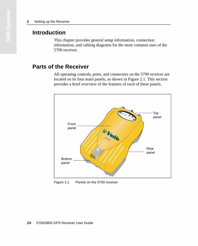
2.2 Parts of the ReceiverAll operating controls, ports, and connectors on the 5700 receiver are located on its four main panels, as shown in Figure 2.1. This section provides a brief overview of the features of each of these panels.
Figure 2.1 Panels on the 5700 receiver
Bottompanel
Toppanel
Frontpanel
Rearpanel
20 5700/5800 GPS Receiver User Guide
Setting up the Receiver 2
5700
Ope
ratio
n
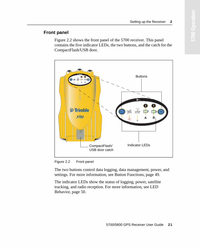
2.2.1 Front panel
Figure 2.2 shows the front panel of the 5700 receiver. This panel contains the five indicator LEDs, the two buttons, and the catch for the CompactFlash/USB door.
Figure 2.2 Front panel
The two buttons control data logging, data management, power, and settings. For more information, see Button Functions, page 49.
The indicator LEDs show the status of logging, power, satellite tracking, and radio reception. For more information, see LED Behavior, page 50.
USB door catch
2 3
t
2 3
t
Buttons
Indicator LEDsCompactFlash/
5700/5800 GPS Receiver User Guide 21
2 Setting up the Receiver
5700
Ope
ratio
n
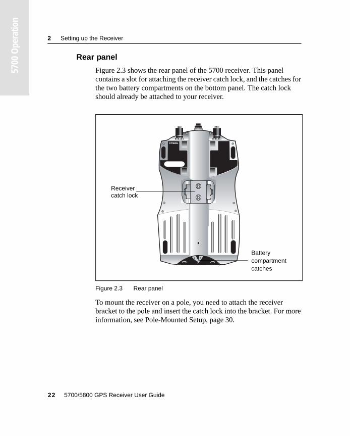
2.2.2 Rear panel
Figure 2.3 shows the rear panel of the 5700 receiver. This panel contains a slot for attaching the receiver catch lock, and the catches for the two battery compartments on the bottom panel. The catch lock should already be attached to your receiver.
Figure 2.3 Rear panel
To mount the receiver on a pole, you need to attach the receiver bracket to the pole and insert the catch lock into the bracket. For more information, see Pole-Mounted Setup, page 30.
compartment
Receiver catch lock
Battery
catches
22 5700/5800 GPS Receiver User Guide
Setting up the Receiver 2
5700
Ope
ratio
n
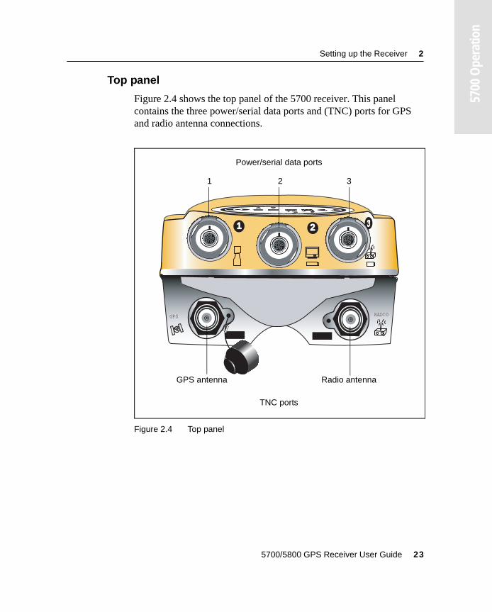
2.2.3 Top panel
Figure 2.4 shows the top panel of the 5700 receiver. This panel contains the three power/serial data ports and (TNC) ports for GPS and radio antenna connections.
Figure 2.4 Top panel
1 2
GPS RADIO
Power/serial data ports
TNC ports
1 2 3
GPS antenna Radio antenna
5700/5800 GPS Receiver User Guide 23
2 Setting up the Receiver
5700
Ope
ratio
n
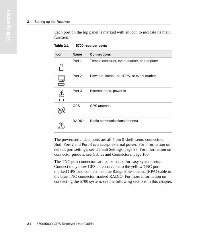
Each port on the top panel is marked with an icon to indicate its main function.
The power/serial data ports are all 7 pin 0-shell Lemo connectors. Both Port 2 and Port 3 can accept external power. For information on default port settings, see Default Settings, page 97. For information on connector pinouts, see Cables and Connectors, page 103.
The TNC port connectors are color-coded for easy system setup. Connect the yellow GPS antenna cable to the yellow TNC port marked GPS, and connect the blue Range Pole antenna (RPA) cable to the blue TNC connector marked RADIO. For more information on connecting the 5700 system, see the following sections in this chapter.
Table 2.1 5700 receiver ports
Icon Name Connections
Port 1 Trimble controller, event marker, or computer
Port 2 Power in, computer, 1PPS, or event marker
Port 3 External radio, power in
GPS GPS antenna
RADIO Radio communications antenna
24 5700/5800 GPS Receiver User Guide
Setting up the Receiver 2
5700
Ope
ratio
n
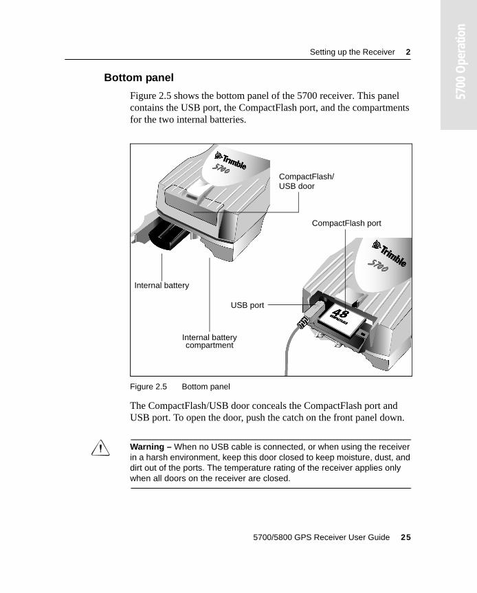
2.2.4 Bottom panel
Figure 2.5 shows the bottom panel of the 5700 receiver. This panel contains the USB port, the CompactFlash port, and the compartments for the two internal batteries.
Figure 2.5 Bottom panel
The CompactFlash/USB door conceals the CompactFlash port and USB port. To open the door, push the catch on the front panel down.
C Warning – When no USB cable is connected, or when using the receiver in a harsh environment, keep this door closed to keep moisture, dust, and dirt out of the ports. The temperature rating of the receiver applies only when all doors on the receiver are closed.
CompactFlash port
USB port
Internal battery
compartmentInternal battery
CompactFlash/ USB door
5700/5800 GPS Receiver User Guide 25
2 Setting up the Receiver
5700
Ope
ratio
n
2.3 Setup Guidelines
Consider the following guidelines when setting up the 5700 receiver.
2.3.1 Environmental conditions
Although the 5700 receiver has a waterproof housing, reasonable care should be taken to keep the unit dry. Avoid exposure to extreme environmental conditions, including:
• Water
• Heat greater than 65° C (149° F)
• Cold less than –40° C (–40° F)
• Corrosive fluids and gases
Avoiding these conditions improves the 5700 receiver’s performance and long-term reliability.
2.3.2 Sources of electrical interference
Avoid the following sources of electrical and magnetic noise:
• Gasoline engines (spark plugs)
• Televisions and PC monitors
• Alternators and generators
• Electric motors
• Equipment with DC-to-AC converters
• Fluorescent lights
• Switching power supplies
26 5700/5800 GPS Receiver User Guide
Setting up the Receiver 2
5700
Ope
ratio
n
2.3.3 General guidelines
The following guidelines apply whenever you set up your receiver for operation:
• When plugging in a Lemo cable, make sure that the red dots on the receiver port and the cable connector line up. Never use force to plug cables in, as this may damage the connector pins.
• When disconnecting a Lemo cable, grasp the cable by the sliding collar or lanyard and pull the cable connector straight out of the port. Do not twist the connector or pull on the cable itself.
• To securely connect a TNC cable, align the cable connector with the receiver receptacle and thread the cable connector onto the receptacle until snug.
• Insert the internal batteries with the battery contacts facing the CompactFlash/USB door. The undersides of the batteries have a center groove for alignment when being inserted into the receiver.
5700/5800 GPS Receiver User Guide 27
2 Setting up the Receiver
5700
Ope
ratio
n
2.4 Postprocessed SetupFor a postprocessed survey, you only need:
• the 5700 receiver
• a Zephyr™ or Zephyr Geodetic antenna
• a GPS antenna cable
Other equipment, as described below, is optional.
To set up the 5700 receiver for a postprocessed survey:
1. Set up the tripod with the tribrach and antenna adapter over the survey mark.
Instead of a tripod, you can use a range pole with a bipod. However, Trimble recommends that you use a tripod for greater stability.
2. Mount the antenna on the tribrach adapter.
3. Use the tripod clip to hang the 5700 receiver on the tripod.
4. Connect the yellow GPS antenna cable to the Zephyr antenna.
5. Connect the other end of the GPS antenna cable to the yellow TNC port on the 5700 receiver.
6. If external power is required, connect a battery with a 0-shell Lemo connection to Port 2 or Port 3 on the receiver.
28 5700/5800 GPS Receiver User Guide
Setting up the Receiver 2
5700
Ope
ratio
n
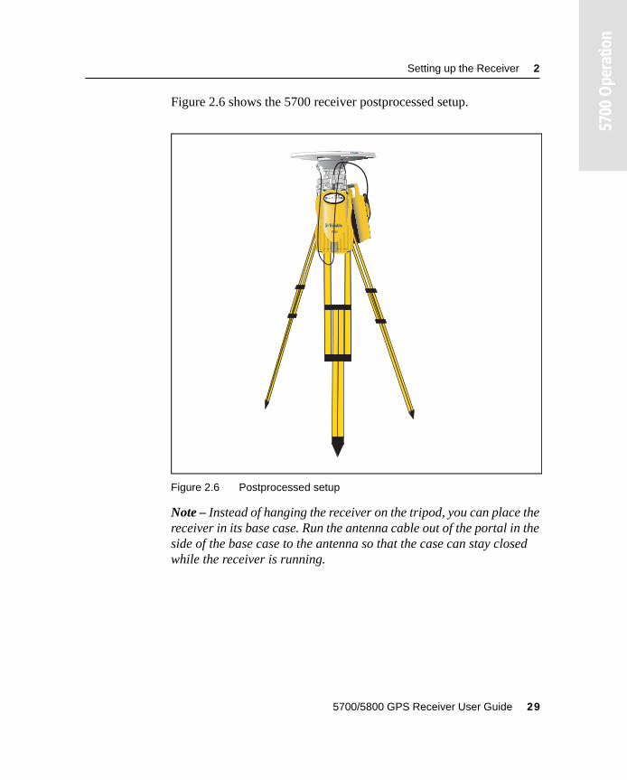
Figure 2.6 shows the 5700 receiver postprocessed setup.
Figure 2.6 Postprocessed setup
Note – Instead of hanging the receiver on the tripod, you can place the receiver in its base case. Run the antenna cable out of the portal in the side of the base case to the antenna so that the case can stay closed while the receiver is running.
2 3
t
5700/5800 GPS Receiver User Guide 29
2 Setting up the Receiver
5700
Ope
ratio
n
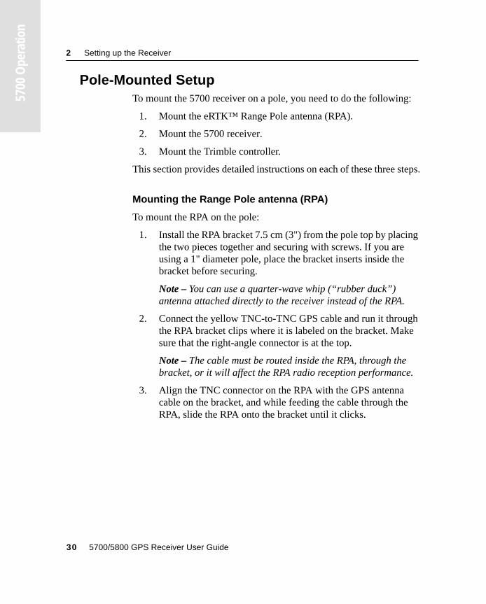
2.5 Pole-Mounted SetupTo mount the 5700 receiver on a pole, you need to do the following:
1. Mount the eRTK™ Range Pole antenna (RPA).
2. Mount the 5700 receiver.
3. Mount the Trimble controller.
This section provides detailed instructions on each of these three steps.
Mounting the Range Pole antenna (RPA)
To mount the RPA on the pole:
1. Install the RPA bracket 7.5 cm (3") from the pole top by placing the two pieces together and securing with screws. If you are using a 1" diameter pole, place the bracket inserts inside the bracket before securing.
Note – You can use a quarter-wave whip (“rubber duck”) antenna attached directly to the receiver instead of the RPA.
2. Connect the yellow TNC-to-TNC GPS cable and run it through the RPA bracket clips where it is labeled on the bracket. Make sure that the right-angle connector is at the top.
Note – The cable must be routed inside the RPA, through the bracket, or it will affect the RPA radio reception performance.
3. Align the TNC connector on the RPA with the GPS antenna cable on the bracket, and while feeding the cable through the RPA, slide the RPA onto the bracket until it clicks.
30 5700/5800 GPS Receiver User Guide
Setting up the Receiver 2
5700
Ope
ratio
n
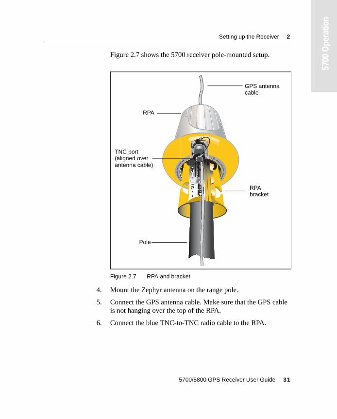
Figure 2.7 shows the 5700 receiver pole-mounted setup.
Figure 2.7 RPA and bracket
4. Mount the Zephyr antenna on the range pole.
5. Connect the GPS antenna cable. Make sure that the GPS cable is not hanging over the top of the RPA.
6. Connect the blue TNC-to-TNC radio cable to the RPA.
DON
O
TRO
UTE
CA
BL
EO
NO
UTS
I
B
LE
RE
CE
IVE
RS
ON
LY
SE
EM
ANU
RPA
GPS antenna cable
Pole
RPAbracket
TNC port (aligned over antenna cable)
5700/5800 GPS Receiver User Guide 31
2 Setting up the Receiver
5700
Ope
ratio
n
Mounting the 5700 receiver
To mount the 5700 receiver on the pole:
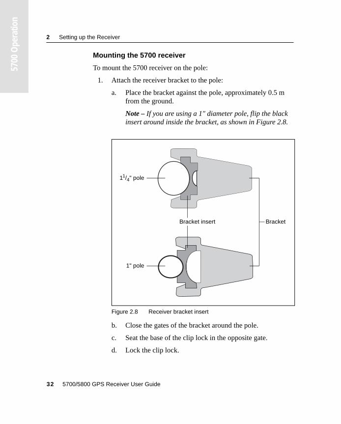
1. Attach the receiver bracket to the pole:
a. Place the bracket against the pole, approximately 0.5 m from the ground.
Note – If you are using a 1" diameter pole, flip the black insert around inside the bracket, as shown in Figure 2.8.
Figure 2.8 Receiver bracket insert
b. Close the gates of the bracket around the pole.
c. Seat the base of the clip lock in the opposite gate.
d. Lock the clip lock.
Bracket insert Bracket
11/4" pole
1" pole
32 5700/5800 GPS Receiver User Guide
Setting up the Receiver 2
5700
Ope
ratio
n
If the clip lock is too tight to be locked, turn it one or two turns counterclockwise and try again. If it is too loose, turn it one or two turns clockwise and try to lock it again.
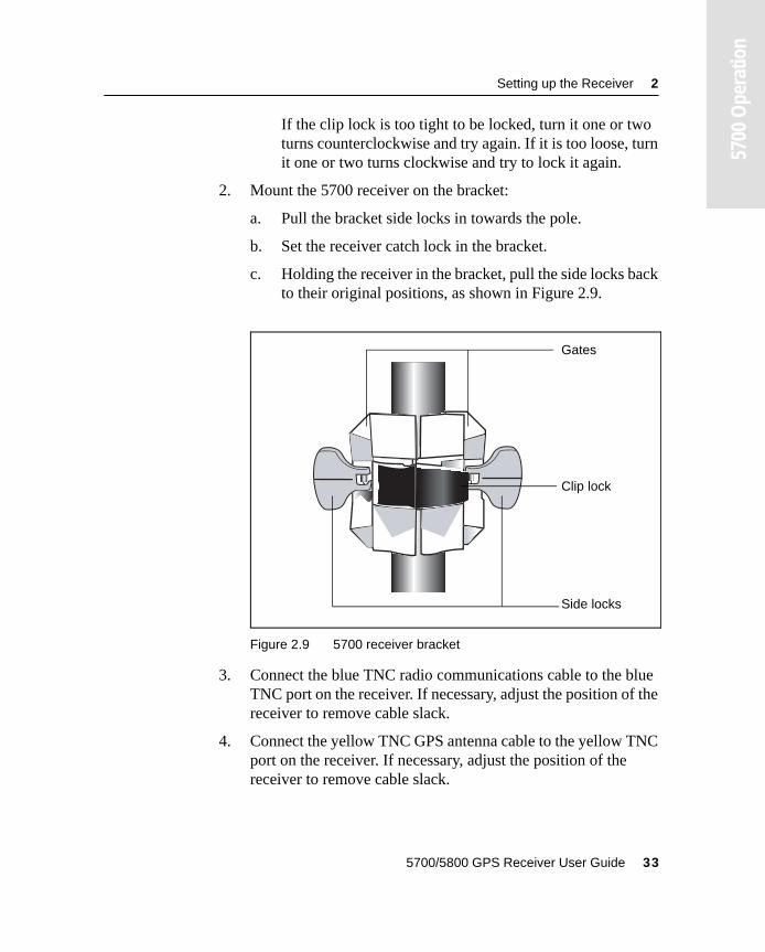
2. Mount the 5700 receiver on the bracket:
a. Pull the bracket side locks in towards the pole.
b. Set the receiver catch lock in the bracket.
c. Holding the receiver in the bracket, pull the side locks back to their original positions, as shown in Figure 2.9.
Figure 2.9 5700 receiver bracket
3. Connect the blue TNC radio communications cable to the blue TNC port on the receiver. If necessary, adjust the position of the receiver to remove cable slack.
4. Connect the yellow TNC GPS antenna cable to the yellow TNC port on the receiver. If necessary, adjust the position of the receiver to remove cable slack.
Clip lock
Gates
Side locks
5700/5800 GPS Receiver User Guide 33
2 Setting up the Receiver
5700
Ope
ratio
n
Mounting the TSC1/TSCe controller
To mount the TSC1/TSCe controller on the pole:
1. Mount the controller bracket on the pole:
a. Place the bracket against the pole at a comfortable height.
b. Rotate the clamping screw on the bracket pole until tight.
c. Place the controller into the cradle assembly and tighten the clamping mechanism.
d. Any cables running down the pole should be run through the machined groove on the inside of the controller bracket.
e. Position the controller in the preferred position for operation by pressing the spring-loaded release button on the cradle, pulling the assembly outward, and rotating the cradle assembly to the desired angle. Reseat the cradle in the proper position by lining up the alignment pins and pushing inward until the release button locks.
2. Connect one end of the 2 ft 0-shell to 0-shell Lemo cable to the TSC1/TSCe controller.
3. Connect the other end of the Lemo cable to Port 1 on the 5700 receiver.
4. Place the hand grip below the controller bracket (or above it, depending on the position of the bracket), with the cables running through the grip.
5. Secure any loose cables, using the velcro cable ties.
34 5700/5800 GPS Receiver User Guide
Setting up the Receiver 2
5700
Ope
ratio
n
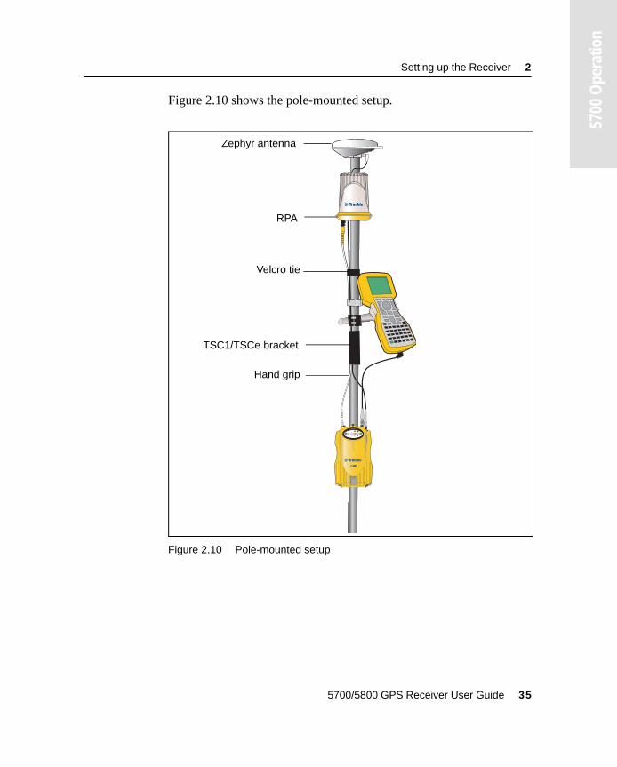
Figure 2.10 shows the pole-mounted setup.
Figure 2.10 Pole-mounted setup
2 3
t
Hand grip
TSC1/TSCe bracket
RPA
Zephyr antenna
Velcro tie
5700/5800 GPS Receiver User Guide 35
2 Setting up the Receiver
5700
Ope
ratio
n
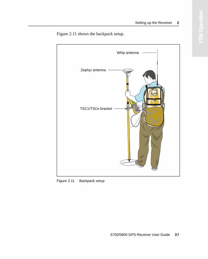
2.6 Backpack SetupBoth the whip and RPA antennae are suitable for use in a backpack. The RPA is installed in the same manner as for the pole-mounted setup (see Pole-Mounted Setup, page 30).
C Warning – The RPA is tuned for operation with the GPS antenna cable running through it. Operating it from a backpack may reduce its operating range. Trimble recommends using the whip antenna.
To set up the 5700 receiver for use in a backpack:
1. Insert the 5700 receiver into the backpack with the ports on the top panel facing upwards and the front panel facing outwards. Secure the receiver around the middle with the velcro strap.
2. Attach the Zephyr antenna to a range pole.
3. Attach the whip antenna mount to one of the fittings on the top of the backpack.
4. The backpack has a feedthrough on both sides at the top and on both sides near the bottom to allow cables to be positioned out of the way of the main zipper. Run the radio communications cable through at the top, and connect it to the blue TNC port on the 5700.
5. Connect the straight end of the yellow GPS cable to the yellow TNC port on the receiver.
6. Run the right-angle connector on the yellow GPS cable through the top or side slot on the backpack, and connect it to the Zephyr antenna.
7. Connect one end of the 6 ft 0-shell to 0-shell cable to Port 1 on the 5700 receiver.
8. Run the 0-shell cable through the side slot of the backpack and connect it to the TSC1/TSCe controller.
36 5700/5800 GPS Receiver User Guide
Setting up the Receiver 2
5700
Ope
ratio
n
Figure 2.11 shows the backpack setup.
Figure 2.11 Backpack setup
2 3
t
Whip antenna
Zephyr antenna
TSC1/TSCe bracket
5700/5800 GPS Receiver User Guide 37
2 Setting up the Receiver
5700
Ope
ratio
n
2.7 Other System ComponentsThis section describes optional components that you can use with the 5700 receiver.
2.7.1 Radios
Radios are the most common data link for Real-Time Kinematic (RTK) surveying. The 5700 receiver is available with an optional internal radio in either the 450 or 900 MHz UHF bands. You can also connect an external radio to Port 3, whether the internal radio is installed or not.
The 5700 receiver supports the following Trimble base radios when using the internal receiver radio:
• TRIMMARK™ 3
• TRIMMARK IIe
• TRIMTALK™ 450S
• SiteNet™ 450
• Sitenet 900
38 5700/5800 GPS Receiver User Guide
Setting up the Receiver 2
5700
Ope
ratio
n
Internal Radio Setup
You can configure the 5700 receiver’s optional internal radio using any of the following:
• the GPS Configurator software
• the WinFlash software
• the Trimble Survey Controller software
For more information, refer to the GPS Configurator Help, the WinFlash Help, or the Trimble Survey Controller User Guide.
By default, the internal UHF radio has only a few frequencies installed. Use WinFlash to configure additional frequencies. For more information, see Adding frequencies for the 450 MHz internal radio, page 87.
External Radio Setup
To use an external radio with the 5700 receiver, you need an external power source for the radio.
To set up a 5700 receiver using an external radio:
1. Connect one end of the yellow GPS antenna cable to the yellow TNC port on the 5700 receiver.
2. Connect the other end of the GPS antenna cable to a Zephyr or Zephyr Geodetic antenna.
3. Connect the external radio to Port 3 on the receiver.
4. Connect a radio antenna to the external radio.
5700/5800 GPS Receiver User Guide 39
2 Setting up the Receiver
5700
Ope
ratio
n
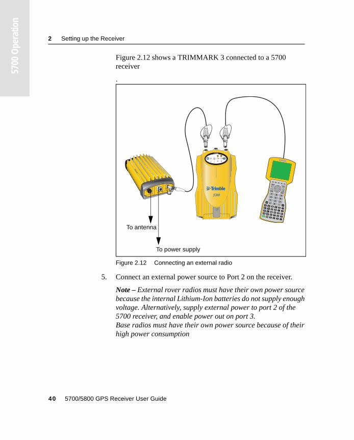
Figure 2.12 shows a TRIMMARK 3 connected to a 5700 receiver
.
Figure 2.12 Connecting an external radio
5. Connect an external power source to Port 2 on the receiver.
Note – External rover radios must have their own power source because the internal Lithium-Ion batteries do not supply enough voltage. Alternatively, supply external power to port 2 of the 5700 receiver, and enable power out on port 3. Base radios must have their own power source because of their high power consumption
2 3
t
To antenna
To power supply
40 5700/5800 GPS Receiver User Guide
Setting up the Receiver 2
5700
Ope
ratio
n
Alternatively, you can apply external power directly to the radio, if it supports it.
You can use a 10 Ah battery, a 6 Ah battery, or camcorder batteries. The choice of power supply depends on the application, and whether you are using the radio as a reference or rover radio. For more information about the power capabilities of the 5700 receiver, see Batteries and Power, page 55.
6. Configure the external radio using Trimble Survey Controller. Alternatively, you can configure a TRIMMARK 3 radio using WinFlash or the configuration software supplied with the radio.
For more information, refer to the Trimble Survey Controller User Guide or the appropriate Help.
7. Set up any other equipment as required, depending on whether you are using the radio as a reference or a rover radio.
2.7.2 Cellular modems
You can use a cellular modem instead of a radio as your data communications link. Cellular modems and other radio links can be used to extend the limits of your surveys.
To connect a cellular modem to a 5700 receiver you need the following:
• 5700 receiver
• A custom-designed cellular modem, or a cellphone that can transmit and receive data
• Serial (cellphone to DB9) cable (supplied with the cellular modem or phone)
• Trimble DB9 to 0-shell Lemo cable
5700/5800 GPS Receiver User Guide 41
2 Setting up the Receiver
5700
Ope
ratio
n
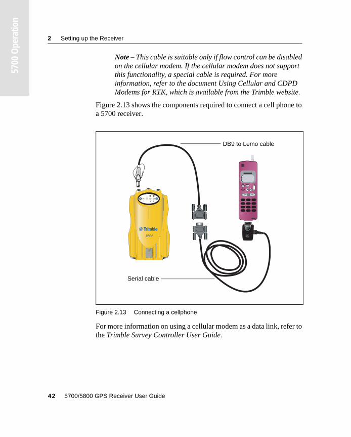
Note – This cable is suitable only if flow control can be disabled on the cellular modem. If the cellular modem does not support this functionality, a special cable is required. For more information, refer to the document Using Cellular and CDPD Modems for RTK, which is available from the Trimble website.
Figure 2.13 shows the components required to connect a cell phone to a 5700 receiver.
Figure 2.13 Connecting a cellphone
For more information on using a cellular modem as a data link, refer to the Trimble Survey Controller User Guide.
PUSHPUSH
c R
2 3
t
Serial cable
DB9 to Lemo cable
42 5700/5800 GPS Receiver User Guide
Setting up the Receiver 2
5700
Ope
ratio
n
2.7.3 Antennas
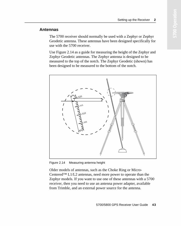
The 5700 receiver should normally be used with a Zephyr or Zephyr Geodetic antenna. These antennas have been designed specifically for use with the 5700 receiver.
Use Figure 2.14 as a guide for measuring the height of the Zephyr and Zephyr Geodetic antennas. The Zephyr antenna is designed to be measured to the top of the notch. The Zephyr Geodetic (shown) has been designed to be measured to the bottom of the notch.
Figure 2.14 Measuring antenna height
Older models of antennas, such as the Choke Ring or Micro-Centered™ L1/L2 antennas, need more power to operate than the Zephyr models. If you want to use one of these antennas with a 5700 receiver, then you need to use an antenna power adapter, available from Trimble, and an external power source for the antenna.
1.520
1.510
1.515
1.505
5700/5800 GPS Receiver User Guide 43
2 Setting up the Receiver
5700
Ope
ratio
n
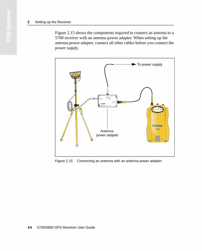
Figure 2.15 shows the components required to connect an antenna to a 5700 receiver with an antenna power adapter. When setting up the antenna power adapter, connect all other cables before you connect the power supply.
Figure 2.15 Connecting an antenna with an antenna power adapter
2 3
t
To power supply
Antenna power adapter
44 5700/5800 GPS Receiver User Guide
Setting up the Receiver 2
5700
Ope
ratio
n
2.7.4 CompactFlash cards
The 5700 receiver logs data internally on CompactFlash cards. However, it only supports Type I CompactFlash cards. Trimble recommends that you use industrial-rated CompactFlash cards, as commercial cards have a limited operating temperature range.
Before logging data to a CompactFlash card, format the card to ensure the integrity of the file system. To format the card, insert it in the 5700 receiver and then hold down p for 30 seconds.
Note – Make sure that you format your CompactFlash card in the receiver. This prevents data on the card from being corrupted if the card is removed while data is being logged. Formatting the card in your PC may cause data corruption, or loss of data.
When inserting the card, make sure that it slides into the card slot properly.
C Warnings: – The 5700 allows for a maximum of 512 files on the CompactFlash card, regardless of the card’s capacity. The file names must be in 8.3 format, otherwise files copied to the CompactFlash card may cause data corruption or loss of data when logging.– If the card does not seat into the pins correctly, do not use force or you may damage the pins. Remove the card and reinsert it carefully.
5700/5800 GPS Receiver User Guide 45

2 Setting up the Receiver
5700
Ope
ratio
n
46 5700/5800 GPS Receiver User Guide
C H A P T E R
3
3 General OperationIn this chapter:
■ Introduction
■ Button functions
■ LED behavior
■ Starting and stopping the receiver
■ Logging data
■ Resetting to defaults
■ Formatting a CompactFlash card
■ Batteries and power
3 General Operation
5700
Ope
ratio
n
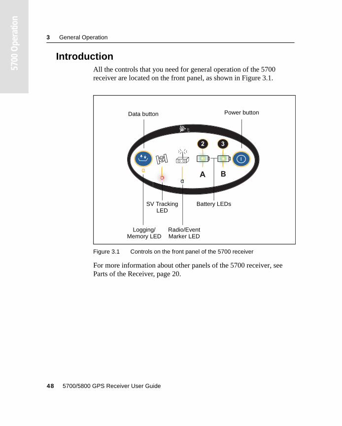
3.1 IntroductionAll the controls that you need for general operation of the 5700 receiver are located on the front panel, as shown in Figure 3.1.
Figure 3.1 Controls on the front panel of the 5700 receiver
For more information about other panels of the 5700 receiver, see Parts of the Receiver, page 20.
2 3
t
Logging/Memory LED
Data button Power button
Battery LEDsSV Tracking
Radio/Event
LED
Marker LED
48 5700/5800 GPS Receiver User Guide
General Operation 3
5700
Ope
ratio
n
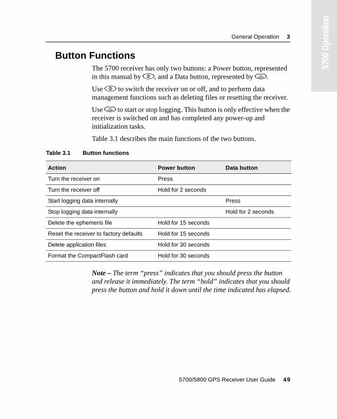
3.2 Button FunctionsThe 5700 receiver has only two buttons: a Power button, represented in this manual by p, and a Data button, represented by d.
Use p to switch the receiver on or off, and to perform data management functions such as deleting files or resetting the receiver.
Use d to start or stop logging. This button is only effective when the receiver is switched on and has completed any power-up and initialization tasks.
Table 3.1 describes the main functions of the two buttons.
Note – The term “press” indicates that you should press the button and release it immediately. The term “hold” indicates that you should press the button and hold it down until the time indicated has elapsed.
Table 3.1 Button functions
Action Power button Data button
Turn the receiver on Press
Turn the receiver off Hold for 2 seconds
Start logging data internally Press
Stop logging data internally Hold for 2 seconds
Delete the ephemeris file Hold for 15 seconds
Reset the receiver to factory defaults Hold for 15 seconds
Delete application files Hold for 30 seconds
Format the CompactFlash card Hold for 30 seconds
5700/5800 GPS Receiver User Guide 49
3 General Operation
5700
Ope
ratio
n
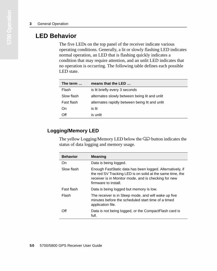
3.3 LED BehaviorThe five LEDs on the top panel of the receiver indicate various operating conditions. Generally, a lit or slowly flashing LED indicates normal operation, an LED that is flashing quickly indicates a condition that may require attention, and an unlit LED indicates that no operation is occurring. The following table defines each possible LED state.
3.3.1 Logging/Memory LED
The yellow Logging/Memory LED below the d button indicates the status of data logging and memory usage.
The term … means that the LED …
Flash is lit briefly every 3 seconds
Slow flash alternates slowly between being lit and unlit
Fast flash alternates rapidly between being lit and unlit
On is lit
Off is unlit
Behavior Meaning
On Data is being logged.
Slow flash Enough FastStatic data has been logged. Alternatively, if the red SV Tracking LED is on solid at the same time, the receiver is in Monitor mode, and is checking for new firmware to install.
Fast flash Data is being logged but memory is low.
Flash The receiver is in Sleep mode, and will wake up five minutes before the scheduled start time of a timed application file.
Off Data is not being logged, or the CompactFlash card is full.
50 5700/5800 GPS Receiver User Guide
General Operation 3
5700
Ope
ratio
n
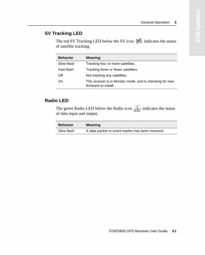
3.3.2 SV Tracking LED
The red SV Tracking LED below the SV icon indicates the status of satellite tracking.
3.3.3 Radio LED
The green Radio LED below the Radio icon indicates the status of data input and output.
Behavior Meaning
Slow flash Tracking four or more satellites.
Fast flash Tracking three or fewer satellites.
Off Not tracking any satellites.
On The receiver is in Monitor mode, and is checking for new firmware to install.
Behavior Meaning
Slow flash A data packet or event marker has been received.
5700/5800 GPS Receiver User Guide 51
3 General Operation
5700
Ope
ratio
n
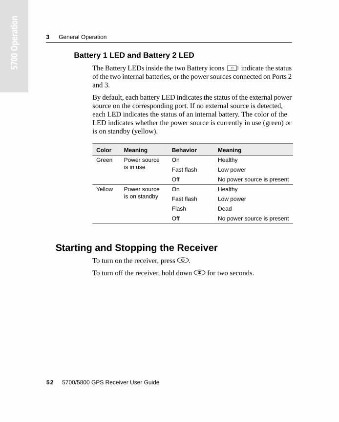
3.3.4 Battery 1 LED and Battery 2 LED
The Battery LEDs inside the two Battery icons indicate the status of the two internal batteries, or the power sources connected on Ports 2 and 3.
By default, each battery LED indicates the status of the external power source on the corresponding port. If no external source is detected, each LED indicates the status of an internal battery. The color of the LED indicates whether the power source is currently in use (green) or is on standby (yellow).
3.4 Starting and Stopping the ReceiverTo turn on the receiver, press p.
To turn off the receiver, hold down p for two seconds.
Color Meaning Behavior Meaning
Green Power source is in use
On Healthy
Fast flash Low power
Off No power source is present
Yellow Power source is on standby
On Healthy
Fast flash Low power
Flash Dead
Off No power source is present
52 5700/5800 GPS Receiver User Guide
General Operation 3
5700
Ope
ratio
n
3.5 Logging DataYou can log data to the CompactFlash card in the 5700 receiver, or alternatively to the survey device.
3.5.1 Logging internally
The 5700 receiver logs GPS data internally on a CompactFlash card. You can then use the Trimble Data Transfer utility to transfer logged data files to your office computer. The transferred files are in Trimble DAT (.dat) format.
C Warning – The 5700 allows for a maximum of 512 files on the CompactFlash card, regardless of the card’s capacity. The file names must be in 8.3 format, otherwise files copied to the CompactFlash card may cause data corruption or loss of data when logging.
Data is logged using the current logging settings configured in the receiver. Data files logged internally are named automatically.
To begin internal logging, press d. The Logging/Memory LED lights up.
To stop logging, hold down d for at least two seconds. The Logging/Memory LED turns off.
Note – When the CompactFlash card is full, the receiver stops logging data, and the Logging/Memory LED switches off. Existing data files are not overwritten.
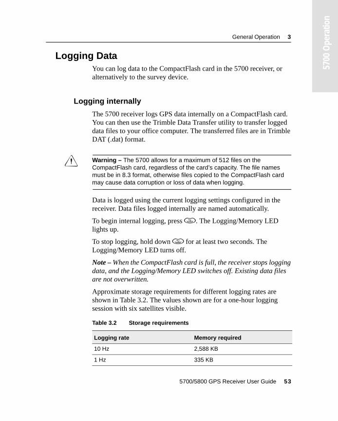
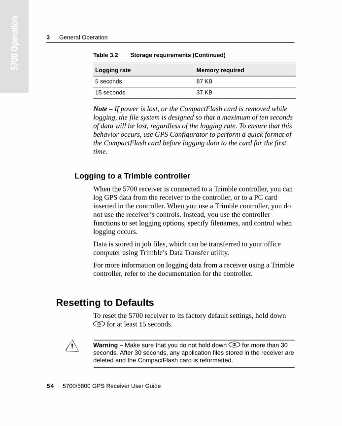
Approximate storage requirements for different logging rates are shown in Table 3.2. The values shown are for a one-hour logging session with six satellites visible.
Table 3.2 Storage requirements
Logging rate Memory required
10 Hz 2,588 KB
1 Hz 335 KB
5700/5800 GPS Receiver User Guide 53
3 General Operation
5700
Ope
ratio
n
Note – If power is lost, or the CompactFlash card is removed while logging, the file system is designed so that a maximum of ten seconds of data will be lost, regardless of the logging rate. To ensure that this behavior occurs, use GPS Configurator to perform a quick format of the CompactFlash card before logging data to the card for the first time.
3.5.2 Logging to a Trimble controller
When the 5700 receiver is connected to a Trimble controller, you can log GPS data from the receiver to the controller, or to a PC card inserted in the controller. When you use a Trimble controller, you do not use the receiver’s controls. Instead, you use the controller functions to set logging options, specify filenames, and control when logging occurs.
Data is stored in job files, which can be transferred to your office computer using Trimble’s Data Transfer utility.
For more information on logging data from a receiver using a Trimble controller, refer to the documentation for the controller.
3.6 Resetting to DefaultsTo reset the 5700 receiver to its factory default settings, hold down p for at least 15 seconds.
C Warning – Make sure that you do not hold down p for more than 30 seconds. After 30 seconds, any application files stored in the receiver are deleted and the CompactFlash card is reformatted.
5 seconds 87 KB
15 seconds 37 KB
Table 3.2 Storage requirements (Continued)
Logging rate Memory required
54 5700/5800 GPS Receiver User Guide
General Operation 3
5700
Ope
ratio
n
Resetting the receiver to its factory defaults also deletes any ephemeris file in the receiver.
For more information, see Chapter 8, Default Settings.
3.7 Formatting a CompactFlash CardTo format a CompactFlash card for use in a 5700 receiver, insert the card in the CompactFlash port, then hold down p for at least 30 seconds. After 15 seconds, the receiver is reset to its factory defaults, and any ephemeris file is deleted. After 30 seconds, any files stored on the card are deleted and the CompactFlash card is reformatted.
C Warning – Formatting a CompactFlash card while it is in the receiver deletes all the data files on the card and all the application files in the receiver.
Note – When you use p to format the CompactFlash card, a quick format is performed. A quick format reformats the card for use with the 5700 receiver and deletes all data on the card. A full format checks the card for errors or bad sectors, and is only necessary if the card is corrupted. To perform a full format, use GPS Configurator. For more information, see GPS Configurator Software, page 80.
3.8 Batteries and PowerThe 5700 receiver can be powered either by its two internal batteries or by an external power source connected to Port 2 or Port 3. The charge provided by the internal batteries depends on the type of survey and operating conditions. Typically, one battery provides about 3.5 hours of power during an RTK survey using the internal radio, and about 5 hours during a survey without the internal radio.
5700/5800 GPS Receiver User Guide 55
3 General Operation
5700
Ope
ratio
n
The external power source is always used in preference to the internal batteries. When there is no external power source connected, or if the external power supply fails, the internal batteries are used. The internal batteries are drained in turn, and the receiver automatically switches to the full battery when the first battery is drained.
If no external power is supplied and both internal batteries are drained, none of the data that you have logged is lost. When internal or external power is restored, the receiver restarts in the same state as when power was lost. For example, if the receiver was logging data, the data file is not corrupted, and when power is restored the receiver resumes logging with the same settings as before.
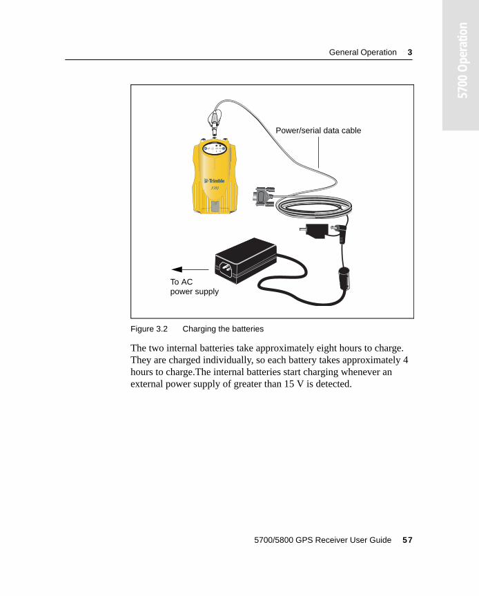
The power supply that is supplied with the 5700 receiver charges the receiver’s internal batteries while they are still in the receiver. To do this, connect the power supply to the power/serial data cable, connect the cable to Port 2 on the receiver, and connect the power supply to an AC power source, as shown in Figure 3.2.
56 5700/5800 GPS Receiver User Guide
General Operation 3
5700
Ope
ratio
n
Figure 3.2 Charging the batteries
The two internal batteries take approximately eight hours to charge. They are charged individually, so each battery takes approximately 4 hours to charge.The internal batteries start charging whenever an external power supply of greater than 15 V is detected.
2 3
t
Power/serial data cable
To AC power supply
5700/5800 GPS Receiver User Guide 57
3 General Operation
5700
Ope
ratio
n
Each 5700 receiver in your system is supplied with two internal lithium-ion battery packs. To charge both sets of batteries, connect both receivers to power supplies as shown in Figure 3.2.
3.8.1 Battery charging and storage
Note – All battery types discharge over time when they are not being used. Batteries also discharge faster in colder temperatures. If a lithium-ion battery is to be stored for long periods of time, make sure it is fully charged before storing and re-charged at least every three months.
To protect the battery from deep discharge (5 volts or less), the 5700 system is designed to switch batteries or cease drawing power when the battery pack discharges to 5.9 volts.
A battery that has reached the deep discharge level cannot be recharged and must be replaced. The following recommendations provide optimal performance and extend the life of your batteries:
• Fully charge all new batteries prior to use.
• Do not allow the batteries to discharge below 5 volts.
• Keep all batteries on continuous charge when not in use. Batteries may be kept on charge indefinitely without damage to the receiver or batteries.
• Do not store batteries in the receiver or external charger unless power is applied.
• If you must store the batteries, fully charge them before storing and then recharge them at least every three months.
58 5700/5800 GPS Receiver User Guide
General Operation 3
5700
Ope
ratio
n
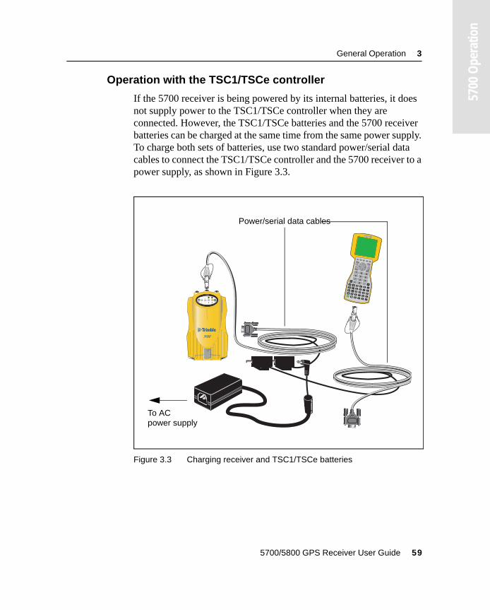
3.8.2 Operation with the TSC1/TSCe controller
If the 5700 receiver is being powered by its internal batteries, it does not supply power to the TSC1/TSCe controller when they are connected. However, the TSC1/TSCe batteries and the 5700 receiver batteries can be charged at the same time from the same power supply. To charge both sets of batteries, use two standard power/serial data cables to connect the TSC1/TSCe controller and the 5700 receiver to a power supply, as shown in Figure 3.3.
Figure 3.3 Charging receiver and TSC1/TSCe batteries
2 3
t
To AC
Power/serial data cables
power supply
5700/5800 GPS Receiver User Guide 59
3 General Operation
5700
Ope
ratio
n
3.8.3 Power output
If the receiver is being supplied with power from an external source, power is automatically output on Port 1. The output voltage is approximately 0.5 V less than the input voltage. Port 1 outputs a maximum voltage of 20 V, even if the input voltage is higher.
You can use GPS Configurator or Trimble Survey Controller to enable power output on Port 3. Port 3 can be enabled for power output regardless of whether power is supplied internally or externally.
On Port 3, the output voltage is approximately 0.5 V less than the input voltage. For example, if power is being supplied from the internal Lithium ion batteries, the maximum battery voltage is 8.4 V, so the maximum output voltage is 7.9 V.
Note – When you start a survey using Trimble Survey Controller, and you are using an external radio, the software automatically enables power output on Port 3.
3.8.4 Firmware
A receiver’s firmware is the program inside the receiver that makes the receiver run and controls the hardware. When you need to upgrade the firmware for your 5700 receiver, Trimble recommends that you use WinFlash. For more information, see WinFlash Software, page 85.
C Warning – Upgrading the firmware deletes all application files on the 5700 receiver.
An alternative method of upgrading your firmware is to copy the .elf file directly to the CompactFlash card from your computer.
To do this:
1. Connect the CompactFlash card to your desktop computer.
2. Using Windows Explorer, copy the .elf file from your computer to the CompactFlash card.
60 5700/5800 GPS Receiver User Guide
General Operation 3
5700
Ope
ratio
n
3. Disconnect the CompactFlash card from your computer and insert it into the receiver.
4. Turn the receiver off.
5. Hold down d and press p.
The receiver starts up in Monitor mode, automatically detects the newer version of the firmware, and installs it. In Monitor mode, the red SV Tracking LED is lit solidly and the yellow Logging/Memory LED flashes slowly.
The upgrade takes about two minutes. Once the upgrade procedure is complete, the receiver restarts automatically.
5700/5800 GPS Receiver User Guide 61

3 General Operation
5700
Ope
ratio
n
62 5700/5800 GPS Receiver User Guide

C H A P T E R
4
4 ConfigurationIn this chapter:
■ Introduction
■ Configuring the receiver in real time
■ Configuring the receiver using application files
■ Application files
4 Configuration
5700
Ope
ratio
n
4.1 IntroductionThe 5700 receiver has no controls for changing settings. It can only be configured using external software such as the GPS Configurator, Configuration Toolbox™, or Trimble Survey Controller software.
There are two ways to configure the 5700 receiver:
• Configuring the receiver in real time
• Applying the settings in an application file
This chapter provides a brief overview of each of these methods, and describes the contents and use of application files.
4.2 Configuring the Receiver in Real TimeThe GPS Configurator, Configuration Toolbox, and Trimble Survey Controller software all support real-time configuration of the 5700 receiver.
When you configure the receiver in real time, you use one of these software applications to specify which settings you want to change. When you apply the changes, the receiver settings change immediately.
Any changes that you apply to the receiver are reflected in the Current application file, which is always present in the receiver. The Current application file always records the most recent configuration, so if you apply further changes (either in real time or using an application file) the Current file is updated and there is no record of the changes that you applied originally.
For more information on configuring the receiver in real time, see Chapter 6, Software Utilities.
64 5700/5800 GPS Receiver User Guide
Configuration 4
5700
Ope
ratio
n
4.3 Configuring the Receiver Using Application FilesAn application file contains information for configuring a receiver. To configure a receiver using an application file, you need to create the application file, transfer it to the receiver, and then apply the file’s settings. Use the Configuration Toolbox software to perform all these tasks.
For more information on applying application files, see Chapter 6, Software Utilities.
4.4 Application FilesAn application file is organized into records. Each record stores configuration information for a particular area of receiver operation. Application files can include the following records:
• File Storage
• General Controls
• Serial Port Baud/Format
• Reference Position
• Logging Rate
• SV Enable/Disable
• Output Message
• Antenna
• Device Control
• Static/Kinematic
• Input Message
• Timed Activation
5700/5800 GPS Receiver User Guide 65
4 Configuration
5700
Ope
ratio
n
An application file does not have to contain all of these records. When you apply an application file, any option that is not included in the records in the file remains at its current setting. For example, if you apply an application file that only specifies the elevation mask to use, all other settings remain as they were before the application file was applied.
You can store up to twenty different application files in battery-backed memory on the receiver. You can apply an application file’s settings at the time it is transferred to the receiver, or at any time afterwards.
4.4.1 Special application files
The 5700 receiver has three special application files, which control important aspects of the receiver’s configuration.
Default application file
The Default application file (Default.cfg) contains the original receiver configuration, and cannot be changed. This file configures the receiver after it is reset. You can reset the receiver by holding down p for at least 15 seconds, or by using the reset option in GPS Configurator.
For more information on the default receiver settings, see Default Settings, page 97.
Although you cannot change or delete the Default application file, you can use a Power Up application file to override any or all of the default settings.
66 5700/5800 GPS Receiver User Guide
Configuration 4
5700
Ope
ratio
n
Current application file
The Current application file (Current.cfg) reflects the current receiver configuration. Whenever you change the receiver’s configuration, either in real time or by applying an application file, the Current file changes to match the new configuration.
You cannot delete the Current file or change it directly, but every change to the receiver’s current configuration is applied to the Current file as well.
When you switch off the receiver then turn it on again, all the settings from the Current application file are applied, so you do not lose any changes that you have made. The only exceptions are the following logging parameters:
• Logging rate
• Position rate
• Elevation mask
These parameters are always reset to the factory default values whenever the receiver is switched off.
Power Up application file
The Power Up application file (Power_up.cfg) is optional. If a Power Up file is present, its settings are applied whenever the receiver is powered up.
In this file, you can specify that the receiver is reset to defaults before the Power Up settings are applied. This ensures that restarting the receiver always results in the same configuration. This method is useful for defining “default” settings for the receiver that differ from those in the Default file, which cannot be changed.
Alternatively, you can specify that the Power Up settings are applied immediately after the Current application file’s settings have been applied. Restarting the receiver results in a configuration that uses your default settings for the options you define in the Power Up file, but the current settings for all other options.
5700/5800 GPS Receiver User Guide 67
4 Configuration
5700
Ope
ratio
n
By default, there is no Power Up application file on the receiver. If you want to use a Power Up application file, you need to create an application file in Configuration Toolbox and make sure that the As auto power up file option is selected in the File page. When you transfer this file to the receiver, it is transferred with the name Power_up.cfg, and becomes the new Power Up file.
The Power Up file is the only special application file that you can overwrite or delete from the receiver.
4.4.2 Timed application files
A timed application file contains a Timed Activation record which specifies when this file is to be applied. The main use of a timed application file is to automatically start or stop logging at a predefined time.
The Timed Activation record specifies:
• the UTC date and time when the application file is to be applied for the first time
• the interval at which the file is to be reapplied
If you do not specify a repeat interval, the settings are applied only once, at the specified time. If the file specifies a repeat interval, the file’s settings are reapplied at the specified interval until the file is deactivated.
Note – If the receiver is logging continuously, the current logging takes precedence over any timed application file stored in the receiver.
Defining timed application files
To send timed application files to a 5700 receiver, set up scheduled survey sessions in GPS Configurator. You can define multiple sessions, each specifying:
• basic logging parameters (data logging rate, position logging rate, and elevation mask)
68 5700/5800 GPS Receiver User Guide
Configuration 4
5700
Ope
ratio
n
• a starting time
• a duration
When you apply the current settings in GPS Configurator, each defined survey session is sent to the 5700 receiver as a pair of timed application files: the first includes the logging settings and start time, and the second contains settings that stop logging at the end time (which is calculated automatically from the duration you specify).
For more information on scheduled survey sessions, refer to the GPS Configurator Help.
The 5700 receiver can store up to 20 application files, so you can define a maximum of 10 scheduled survey sessions (10 pairs of start/stop timed application files).
Note – You cannot use Configuration Toolbox to define timed application files.
Sleep mode
Whenever you press p to turn off the 5700 receiver, it checks for a timed application file that is due to be activated in the future. If one exists, the receiver goes into Sleep mode instead of powering down.
In Sleep mode, the yellow Logging/Memory LED flashes every three seconds. The receiver wakes up five minutes before the scheduled activation time, so that it is ready to begin logging at the scheduled time.
5700/5800 GPS Receiver User Guide 69
4 Configuration
5700
Ope
ratio
n
4.4.3 Applying application files
An application file’s settings do not affect the receiver’s configuration until you apply the application file. You can do this at the same time that you save the file. Alternatively, save the file on the computer or in the receiver, then open it later and apply its settings.
Note – If the application file is a timed file, its settings do not take effect as soon as you apply the file, but at the time that the file specifies for its activation.
4.4.4 Storing application files
You can store application files that you create in Configuration Toolbox on both your receiver and computer. Each file can, for example, represent a different user sharing the same receiver, or a particular mode of operation or survey style. Saving application files on your computer as well as in your receiver is optional, but it is useful because:
• it gives you a permanent copy of the settings you have sent to a receiver, for audit or your own reference
• you can use the same file to configure multiple receivers identically
• you can use an existing application file as a template for creating other application files with similar settings
4.4.5 Naming application files
The filename that you use to store the application file in the computer and the name under which the file is stored in the receiver are always the same. This makes recognizing and keeping track of your application files easier. If you change the name of the file on the receiver, this changes the filename used to store the application file on your computer. Similarly, if you change the filename on the computer, the name of the file in the receiver will change.
70 5700/5800 GPS Receiver User Guide
C H A P T E R
5
5 Transferring DataIn this chapter:
■ Introduction
■ Connecting to the office computer
■ Transferring data
■ Transferring files directly from a CompactFlash card
■ Deleting files in the receiver
■ Supported file types
5 Transferring Data
5700
Ope
ratio
n
5.1 IntroductionThe 5700 receiver keeps satellite measurements and other data in files stored on a CompactFlash card. These files cannot be processed until you transfer them to your office computer.
Note – The 5700 receiver supports a maximum of 512 files on the CompactFlash cards.
On returning to the office after completing a survey, transfer the field data to a computer that has the Trimble Geomatics Office™ software installed. You can then process the survey data in Trimble Geomatics Office to produce baselines and coordinates.
72 5700/5800 GPS Receiver User Guide
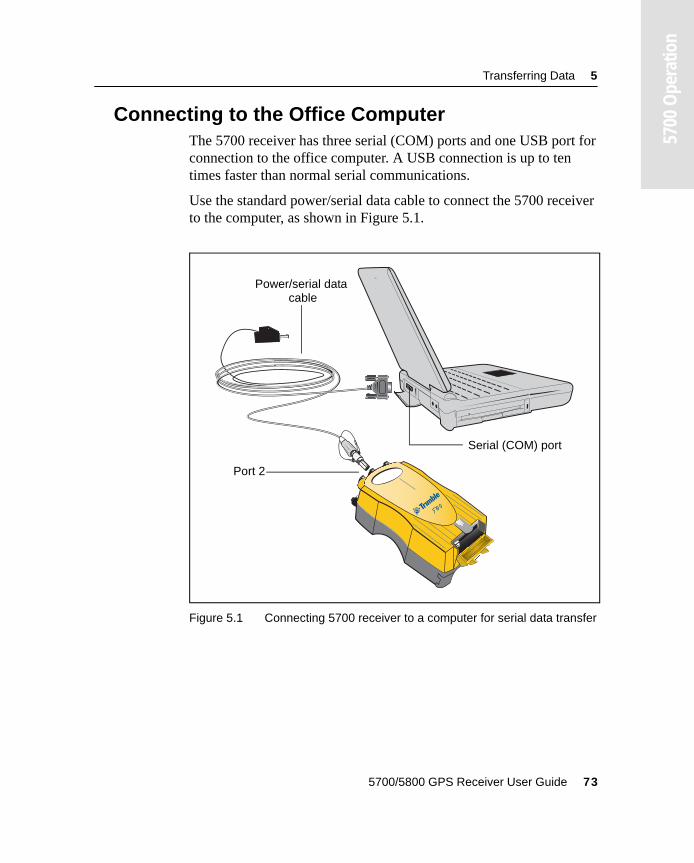
Transferring Data 5
5700
Ope
ratio
n
5.2 Connecting to the Office ComputerThe 5700 receiver has three serial (COM) ports and one USB port for connection to the office computer. A USB connection is up to ten times faster than normal serial communications.
Use the standard power/serial data cable to connect the 5700 receiver to the computer, as shown in Figure 5.1.
Figure 5.1 Connecting 5700 receiver to a computer for serial data transfer
Power/serial data
Port 2
Serial (COM) port
cable
5700/5800 GPS Receiver User Guide 73
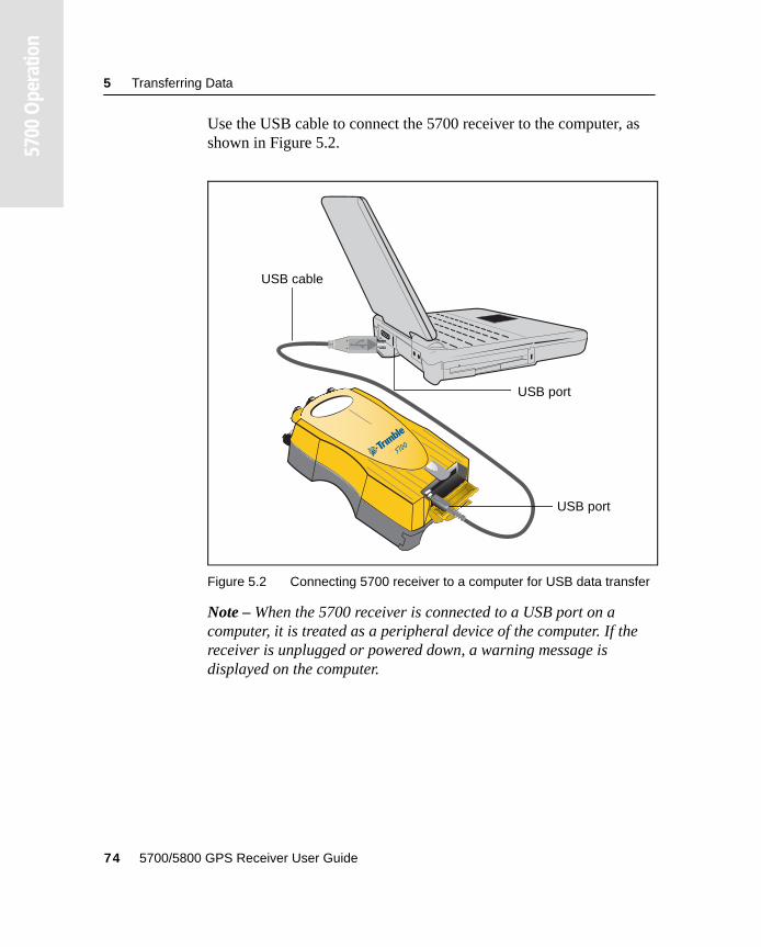
5 Transferring Data
5700
Ope
ratio
n
Use the USB cable to connect the 5700 receiver to the computer, as shown in Figure 5.2.
Figure 5.2 Connecting 5700 receiver to a computer for USB data transfer
Note – When the 5700 receiver is connected to a USB port on a computer, it is treated as a peripheral device of the computer. If the receiver is unplugged or powered down, a warning message is displayed on the computer.
USB cable
USB port
USB port
74 5700/5800 GPS Receiver User Guide
Transferring Data 5
5700
Ope
ratio
n
5.3 Transferring DataTransfer the data files to the computer using the Trimble Data Transfer utility. You can run this utility as a standalone program or from within Trimble Geomatics Office. For more information about the transfer process, refer to the Data Transfer Help.
Note – When you connect to a 5700 receiver in the Data Transfer utility, you must use a GPS Receiver (5000 Series) device definition. If you use a GPS Receiver (4000 Series) device definition, the Data Transfer utility will be unable to establish communication with the 5700 receiver.
When transfer is complete, the Data Transfer utility automatically converts the file to the DAT format. If you are using Data Transfer from within Trimble Geomatics Office, the Check-in dialog appears. For more information, refer to the Trimble Geomatics Office User Guide.
Note – A file in DAT format is approximately six times the size of the corresponding file in the 5700 receiver’s internal format. Before transferring files, make sure that there is enough space on your computer.
5700/5800 GPS Receiver User Guide 75
5 Transferring Data
5700
Ope
ratio
n
5.4 Transferring Files Directly from a CompactFlash Card
All data is stored in a 5700 receiver on an internal CompactFlash card. There are two ways to transfer files between the receiver and your office computer:
• Connect the receiver to the office computer and use the Data Transfer utility to transfer files.
• Remove the CompactFlash card from the receiver and connect it directly to your office computer, where it functions like a normal disk drive. Use Windows Explorer to transfer files.
When you use the Data Transfer utility to transfer data files from the CompactFlash card while it is still inserted in the 5700 receiver, the Data Transfer utility converts the raw receiver data (.T00) files you select into the Trimble DAT file format.
However, if you connect the CompactFlash card to your computer and then copy or move files to your computer, it treats the card like any other disk drive, and transfers the files without converting them. You need to convert these raw receiver files to DAT format files before you can use them on your office computer.
You can convert receiver data files by using a Windows Explorer extension which is installed on your computer when you install the Data Transfer utility.
Note – Although this extension is only available if you have the Data Transfer utility installed, you do not have to run the Data Transfer utility to use it.
76 5700/5800 GPS Receiver User Guide
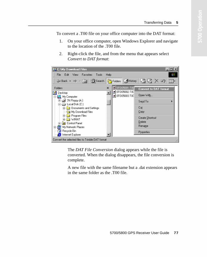
Transferring Data 5
5700
Ope
ratio
n
To convert a .T00 file on your office computer into the DAT format:
1. On your office computer, open Windows Explorer and navigate to the location of the .T00 file.
2. Right-click the file, and from the menu that appears select Convert to DAT format:
The DAT File Conversion dialog appears while the file is converted. When the dialog disappears, the file conversion is complete.
A new file with the same filename but a .dat extension appears in the same folder as the .T00 file.
5700/5800 GPS Receiver User Guide 77
5 Transferring Data
5700
Ope
ratio
n
5.5 Deleting Files in the ReceiverYou can delete files stored in the 5700 receiver at any time. Do one of the following:
• Use the Data Transfer utility in Trimble Geomatics Office.
• Use the TSC1/TSCe controller.
• Hold down the power button p for 30 seconds after the receiver has been powered on. (When you use this method, all data is deleted, and the CompactFlash card is reformatted.)
• Use GPS Configurator.
5.6 Supported File TypesTable 5.1 shows the file types that you can transfer to or from a 5700 receiver, and the software or utility that you must use to transfer each file type.
Note – The 5700 receiver supports a maximum of 512 files on the CompactFlash card. Files stored on the compact flash must be 8.3 format. The 5700 receiver does not support extended file names.
Table 5.1 Supported file types
File Type Extensions Transfer from 5700 receiver?
Transfer to 5700 receiver?
Software
Ephemeris .eph Yes No Data Transfer
Raw observations .T00,.dat Yes No Data Transfer
Receiver firmware files .elf No Yes WinFlash
Application files .cfg Yes Yes Configuration Toolbox
78 5700/5800 GPS Receiver User Guide

C H A P T E R
6
6 Software UtilitiesIn this chapter:
■ Introduction
■ GPS Configurator software
■ Configuration Toolbox software
■ WinFlash software
6 Software Utilities
5700
Ope
ratio
n
6.1 IntroductionThis chapter provides information on the software utilities that you can use with the 5700 receiver.
6.2 GPS Configurator SoftwareGPS Configurator is a Microsoft Windows application that configures selected Trimble GPS receivers.
GPS Configurator lets you:
• check current receiver settings and operation
• change receiver settings in real time
6.2.1 Installing GPS Configurator
A copy of GPS Configurator is included on the 5700/5800 GPS Receiver CD.
To install the software:
1. Insert the CD into the CD drive on your computer.
2. Using Windows Explorer, navigate to the CD drive.
3. Double-click Setup.exe.
4. Follow the onscreen instructions.
80 5700/5800 GPS Receiver User Guide
Software Utilities 6
5700
Ope
ratio
n
6.2.2 Configuring the 5700 receiver
To configure a 5700 receiver using GPS Configurator:
1. Connect Port 1, 2, or 3 on the receiver to a serial (COM) port on the computer and apply power.
2. To start GPS Configurator, click , then select Programs / Trimble / GPS Configurator / GPS Configurator.
The software automatically establishes a connection with the 5700 receiver.
3. Make appropriate selections for your required receiver settings.
For more information, refer to the GPS Configurator Help.
4. Click Apply.
The settings in GPS Configurator are applied to the receiver.
5700/5800 GPS Receiver User Guide 81
6 Software Utilities
5700
Ope
ratio
n
6.3 Configuration Toolbox SoftwareThe Configuration Toolbox software is a Windows application that provides a graphical user interface to help you configure selected Trimble GPS receivers.
Configuration Toolbox lets you:
• create and edit application files
• transfer application files to and from the receiver
• manage application files stored in the receiver
For more information, see Application Files, page 65.
6.3.1 Installing Configuration Toolbox
A copy of Configuration Toolbox is included on the 5700/5800 GPS Receiver CD.
To install the software:
1. Insert the CD into the CD drive on your computer.
2. Using Windows Explorer, navigate to the CD drive.
3. Double-click Setup.exe.
4. Follow the onscreen instructions.
6.3.2 Creating and editing application files
You can create an application file and transfer it to the receiver in several different ways. The general workflow includes the following steps:
1. Create and save the application file in Configuration Toolbox.
2. Connect the receiver to the computer and apply power.
3. Open the desired application file in Configuration Toolbox.
4. Transfer this application file to the receiver.
82 5700/5800 GPS Receiver User Guide
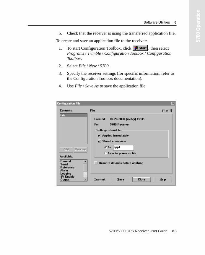
Software Utilities 6
5700
Ope
ratio
n
5. Check that the receiver is using the transferred application file.
To create and save an application file to the receiver:
1. To start Configuration Toolbox, click , then select Programs / Trimble / Configuration Toolbox / Configuration Toolbox.
2. Select File / New / 5700.
3. Specify the receiver settings (for specific information, refer to the Configuration Toolbox documentation).
4. Use File / Save As to save the application file
5700/5800 GPS Receiver User Guide 83
6 Software Utilities
5700
Ope
ratio
n
To transfer the application file to the receiver:
1. Connect the power/serial data cable to Port 1 on the 5700 receiver.
2. Connect the female DB9 connector on the other end of the power/serial data cable to a serial (COM) port on the computer.
3. Select File / Open to open the desired application file.
4. With the file open and the Configuration File dialog open, select Communications / Transmit File.
A message appears informing you that the application file has been successfully transferred. If an error occurs, select Communications / Transmit File again. This overrides any incompatibility in baud rates and enables successful communication.
5. To check whether the transfer was successful, close the Configuration File dialog and select Communications / Get File.
A list of all application files in the 5700 receiver appears. If you selected Apply Immediately in the application file, the Current application file will contain the settings in the new file.
6. To apply a different file, select the file you require from the list and then select Communications / Activate File.
84 5700/5800 GPS Receiver User Guide
Software Utilities 6
5700
Ope
ratio
n
6.4 WinFlash SoftwareWinFlash communicates with Trimble products to perform various functions including:
• installing software, firmware, and option upgrades
• running diagnostics (for example, retrieving configuration information)
• configuring radios
For more information, online help is also available when using WinFlash.
Note – WinFlash is a 32-bit application, so the local computer’s operating system must be Microsoft Windows 95, 98, NT, 2000, or Me. WinFlash does not run under earlier versions of Windows.
6.4.1 Installing WinFlash
WinFlash can be installed from the 5700/5800 GPS Receiver CD, or from the Trimble website.
Installing WinFlash from the 5700/5800 GPS Receiver CD
A copy of WinFlash is included on the 5700/5800 GPS Receiver CD.
To install WinFlash from a CD:
1. Insert the disk into the CD drive on your computer.
2. Using Windows Explorer, navigate to the CD drive.
3. Double-click Setup.exe.
4. Follow the onscreen instructions.
5700/5800 GPS Receiver User Guide 85
6 Software Utilities
5700
Ope
ratio
n
6.4.2 Upgrading firmware
Your 5700 receiver is supplied with the latest version of receiver firmware installed. If a later version becomes available, upgrade the firmware installed on your receiver.
WinFlash guides you through the firmware upgrade process. The steps required are described below. For more information, refer to the WinFlash Help.
To upgrade the 5700 receiver firmware:
1. Start WinFlash.
The Device Configuration screen appears.
2. From the Device type list select 5700 Receiver.
3. From the PC serial port field select the serial (COM) port on the computer that the receiver is connected to.
4. Click Next.
The Operation Selection screen appears. The Operations list shows all of the supported operations for the selected device. A description of the selected operation is shown in the Description field.
5. Select GPS software upgrade and click Next.
The GPS Software Selection window appears. This screen prompts you to select the software that you want to install on the 5700 receiver.
6. Select the latest version from the Available Software list and click Next.
The Settings Review window appears. This screen prompts you to connect the receiver, suggests a connection method, and then lists the receiver configuration and selected operation.
86 5700/5800 GPS Receiver User Guide
Software Utilities 6
5700
Ope
ratio
n
7. If all is correct, click Finish.
Based on the selections shown above, the Software Upgrade window appears and shows the status of the operation (for example, Establishing communication with the 5700. Please wait.).
8. Click OK.
The Software Upgrade window appears again and states that the operation was completed successfully.
9. Click Menu to select another operation, or click Exit to quit WinFlash.
10. If you click Exit, another screen appears asking you to confirm that you want to quit WinFlash. Click OK.
6.4.3 Adding frequencies for the 450 MHz internal radio
If your 5700 receiver has the optional internal radio installed, you can use WinFlash to add frequencies to the default list.
To add radio frequencies:
1. Start WinFlash.
The Device Configuration screen appears.
2. From the Device type list select 5700 Receiver.
3. From the PC serial port field select the serial (COM) port on the computer that the receiver is connected to.
4. Click Next.
The Operation Selection screen appears. The Operations list shows all of the supported operations for the selected device. A description of the selected operation is shown in the Description field.
5. Select Configure Radio and click Next.
5700/5800 GPS Receiver User Guide 87
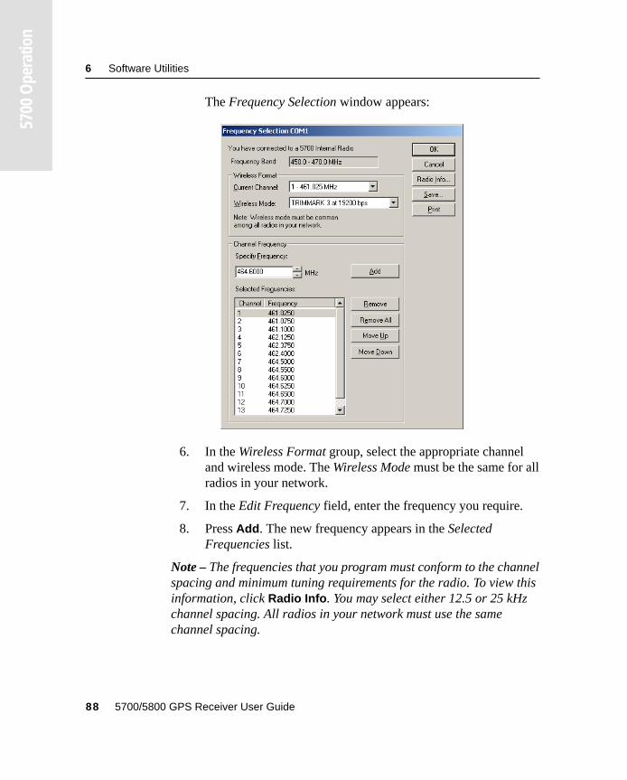
6 Software Utilities
5700
Ope
ratio
n
The Frequency Selection window appears:
6. In the Wireless Format group, select the appropriate channel and wireless mode. The Wireless Mode must be the same for all radios in your network.
7. In the Edit Frequency field, enter the frequency you require.
8. Press Add. The new frequency appears in the Selected Frequencies list.
Note – The frequencies that you program must conform to the channel spacing and minimum tuning requirements for the radio. To view this information, click Radio Info. You may select either 12.5 or 25 kHz channel spacing. All radios in your network must use the same channel spacing.
88 5700/5800 GPS Receiver User Guide
Software Utilities 6
5700
Ope
ratio
n
9. When you have configured all the frequencies you require, click OK.
WinFlash updates the 5700 receiver’s radio frequencies and then restarts the receiver.
6.4.4 Configuring the internal 900 MHz radio setup
To configure the internal 900 MHz radio, use one of the following:
• Trimble Survey Controller running on a Trimble controller
• WinFlash (provided on the Trimble 5700/5800 GPS Receiver CD)
The internal radio has 40 selectable networks. You must choose the same network that is configured in the base radio you want to receive from.
Trimble Survey Controller
To configure the radio network using Trimble Survey Controller:
1. Connect the data/power cable to the controller and the receiver and turn on the controller. The receiver starts automatically.
2. From the main menu on the controller, select Configuration.
3. In the dialog that appears, select Survey styles, then from the Type field, select RTK.
4. Select Rover radio, then from the Type field select Trimble Internal.
5. Tap the Connect softkey.
6. Once connected, in the Network number field enter the number of the network set on your base radio.
Note – The Base Radio Mode field is not used here.
7. Tap the Enter softkey to complete configuration.
5700/5800 GPS Receiver User Guide 89
6 Software Utilities
5700
Ope
ratio
n
WinFlash
To configure the radio network using WinFlash:
1. Connect the data/power cable to Port 1 on the receiver.
2. Connect the female DE-9 connector on the other end of the data/power cable to a serial (COM) port on the computer.
3. Start WinFlash. The Device Configuration dialog appears.
4. From the Device type list, select 5700 Receiver.
5. From the PC serial port field, select the serial port on the computer that the receiver is connected to and click Next.
6. From the Operation selection dialog, select Configure radio and click Next.
7. Confirm that your current settings are correct and click Finish. The Configure 900MHz radio dialog appears.
8. In the Network number field, select the same network that is set on your base radio.
9. In the Country setting field, select one of the following (according to how your base radio was shipped):
– Your country (if available). This sets the radio to the a specific frequency range being transmitted by the base radio.
– A single frequency. This limits the frequencies used to those authorized in your particular country.
10. Click OK.
WinFlash updates the radio settings and then restarts the receiver.
90 5700/5800 GPS Receiver User Guide

C H A P T E R
7
7 SpecificationsIn this chapter:
■ Introduction
■ Physical specifications
■ Positioning specifications
■ Technical specifications
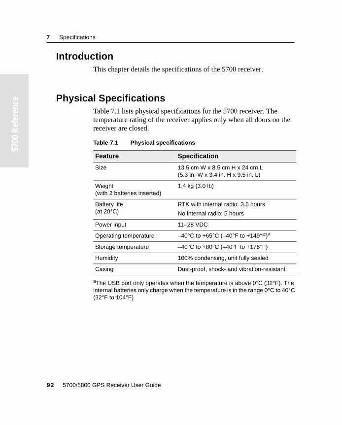
7 Specifications
55700
Ref
eren
ce
7.1 IntroductionThis chapter details the specifications of the 5700 receiver.
7.2 Physical SpecificationsTable 7.1 lists physical specifications for the 5700 receiver. The temperature rating of the receiver applies only when all doors on the receiver are closed.
Table 7.1 Physical specifications
Feature Specification
Size 13.5 cm W x 8.5 cm H x 24 cm L(5.3 in. W x 3.4 in. H x 9.5 in. L)
Weight (with 2 batteries inserted)
1.4 kg (3.0 lb)
Battery life(at 20°C)
RTK with internal radio: 3.5 hours
No internal radio: 5 hours
Power input 11–28 VDC
Operating temperature –40°C to +65°C (–40°F to +149°F)a
aThe USB port only operates when the temperature is above 0°C (32°F). The internal batteries only charge when the temperature is in the range 0°C to 40°C (32°F to 104°F)
Storage temperature –40°C to +80°C (–40°F to +176°F)
Humidity 100% condensing, unit fully sealed
Casing Dust-proof, shock- and vibration-resistant
92 5700/5800 GPS Receiver User Guide
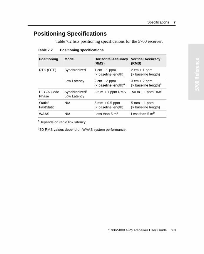
Specifications 7
55700
Ref
eren
ce
7.3 Positioning SpecificationsTable 7.2 lists positioning specifications for the 5700 receiver.
Table 7.2 Positioning specifications
Positioning Mode Horizontal Accuracy (RMS)
Vertical Accuracy (RMS)
RTK (OTF) Synchronized 1 cm + 1 ppm(× baseline length)
2 cm + 1 ppm(× baseline length)
Low Latency 2 cm + 2 ppm (× baseline length)a
aDepends on radio link latency.
3 cm + 2 ppm (× baseline length)a
L1 C/A Code Phase
Synchronized/Low Latency
.25 m + 1 ppm RMS .50 m + 1 ppm RMS
Static/FastStatic
N/A 5 mm + 0.5 ppm(× baseline length)
5 mm + 1 ppm(× baseline length)
WAAS N/A Less than 5 mb
b3D RMS values depend on WAAS system performance.
Less than 5 mb
5700/5800 GPS Receiver User Guide 93
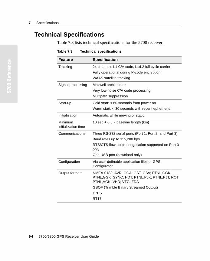
7 Specifications
55700
Ref
eren
ce
7.4 Technical SpecificationsTable 7.3 lists technical specifications for the 5700 receiver.
Table 7.3 Technical specifications
Feature Specification
Tracking 24 channels L1 C/A code, L1/L2 full cycle carrier
Fully operational during P-code encryption
WAAS satellite tracking
Signal processing Maxwell architecture
Very low-noise C/A code processing
Multipath suppression
Start-up Cold start: < 60 seconds from power on
Warm start: < 30 seconds with recent ephemeris
Initialization Automatic while moving or static
Minimum initialization time
10 sec + 0.5 × baseline length (km)
Communications Three RS-232 serial ports (Port 1, Port 2, and Port 3)
Baud rates up to 115,200 bps
RTS/CTS flow control negotiation supported on Port 3 only
One USB port (download only)
Configuration Via user-definable application files or GPS Configurator
Output formats NMEA-0183: AVR; GGA; GST; GSV; PTNL,GGK; PTNL,GGK_SYNC; HDT; PTNL,PJK; PTNL,PJT; ROT PTNL,VGK; VHD; VTG; ZDA
GSOF (Trimble Binary Streamed Output)
1PPS
RT17
94 5700/5800 GPS Receiver User Guide

C H A P T E R
8
8 Default SettingsIn this chapter:
■ Introduction
■ Default settings
■ Resetting to factory defaults
■ Examples
8 Default Settings
55700
Ref
eren
ce
8.1 IntroductionAll 5700 receiver settings are stored in application files. The Default application file, Default.cfg, is stored permanently in the receiver, and contains the factory default settings for the 5700 receiver. Whenever the receiver is reset to its factory defaults, the current settings (stored in the Current application file, Current.cfg) are reset to the values in the Default application file.
You cannot modify the Default application file. However, if there is a Power Up application file (Power_Up.cfg) in the receiver, the settings in this file can be applied immediately after the Default application file, overriding the factory defaults.
For more information about application files, see Application Files, page 65.
96 5700/5800 GPS Receiver User Guide
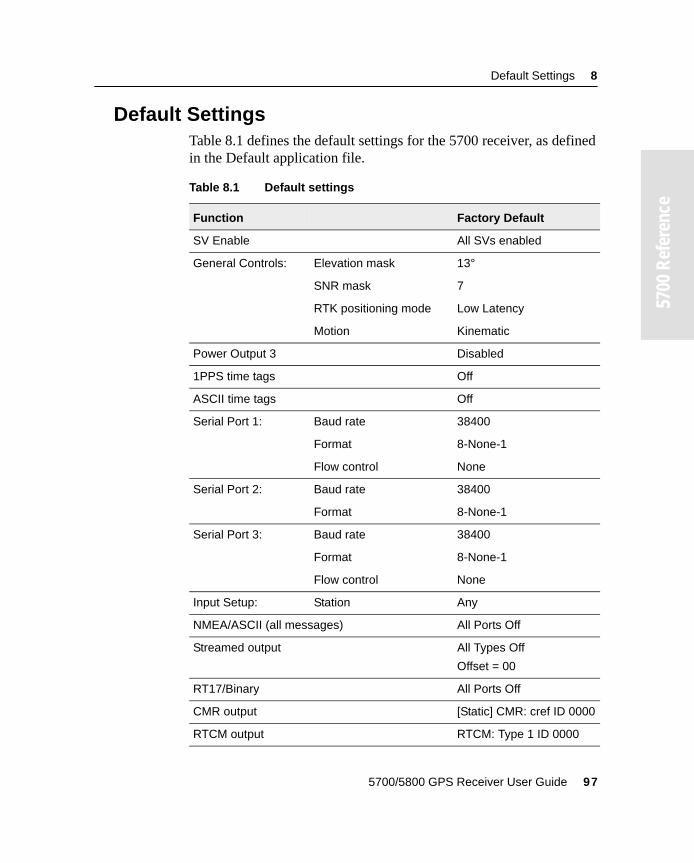
Default Settings 8
55700
Ref
eren
ce
8.2 Default SettingsTable 8.1 defines the default settings for the 5700 receiver, as defined in the Default application file.
Table 8.1 Default settings
Function Factory Default
SV Enable All SVs enabled
General Controls: Elevation mask 13°
SNR mask 7
RTK positioning mode Low Latency
Motion Kinematic
Power Output 3 Disabled
1PPS time tags Off
ASCII time tags Off
Serial Port 1: Baud rate 38400
Format 8-None-1
Flow control None
Serial Port 2: Baud rate 38400
Format 8-None-1
Serial Port 3: Baud rate 38400
Format 8-None-1
Flow control None
Input Setup: Station Any
NMEA/ASCII (all messages) All Ports Off
Streamed output All Types Off
Offset = 00
RT17/Binary All Ports Off
CMR output [Static] CMR: cref ID 0000
RTCM output RTCM: Type 1 ID 0000
5700/5800 GPS Receiver User Guide 97
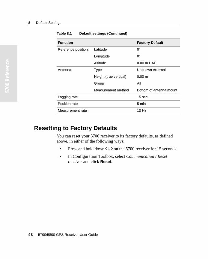
8 Default Settings
55700
Ref
eren
ce
8.3 Resetting to Factory DefaultsYou can reset your 5700 receiver to its factory defaults, as defined above, in either of the following ways:
• Press and hold down p on the 5700 receiver for 15 seconds.
• In Configuration Toolbox, select Communication / Reset receiver and click Reset.
Reference position: Latitude 0°
Longitude 0°
Altitude 0.00 m HAE
Antenna: Type Unknown external
Height (true vertical) 0.00 m
Group All
Measurement method Bottom of antenna mount
Logging rate 15 sec
Position rate 5 min
Measurement rate 10 Hz
Table 8.1 Default settings (Continued)
Function Factory Default
98 5700/5800 GPS Receiver User Guide
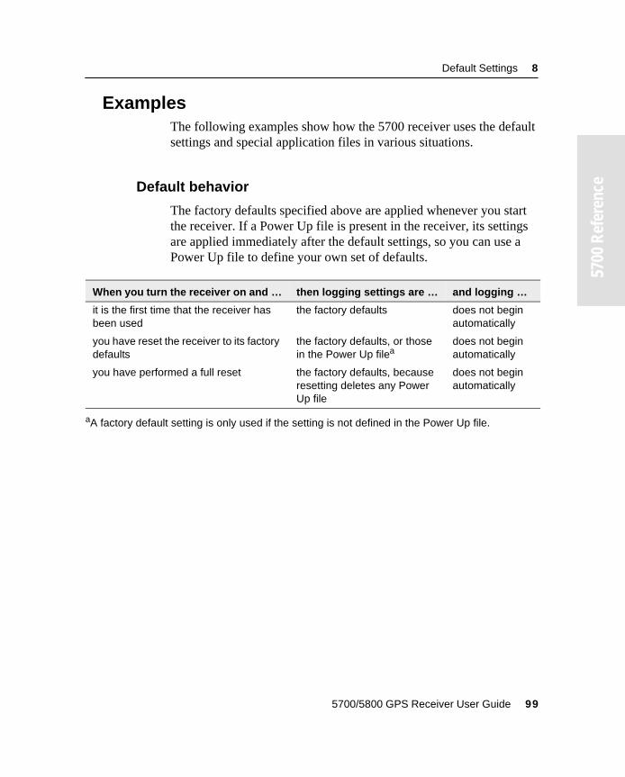
Default Settings 8
55700
Ref
eren
ce
8.4 ExamplesThe following examples show how the 5700 receiver uses the default settings and special application files in various situations.
8.4.1 Default behavior
The factory defaults specified above are applied whenever you start the receiver. If a Power Up file is present in the receiver, its settings are applied immediately after the default settings, so you can use a Power Up file to define your own set of defaults.
When you turn the receiver on and … then logging settings are … and logging …
it is the first time that the receiver has been used
the factory defaults does not begin automatically
you have reset the receiver to its factory defaults
the factory defaults, or those in the Power Up filea
aA factory default setting is only used if the setting is not defined in the Power Up file.
does not begin automatically
you have performed a full reset the factory defaults, because resetting deletes any Power Up file
does not begin automatically
5700/5800 GPS Receiver User Guide 99
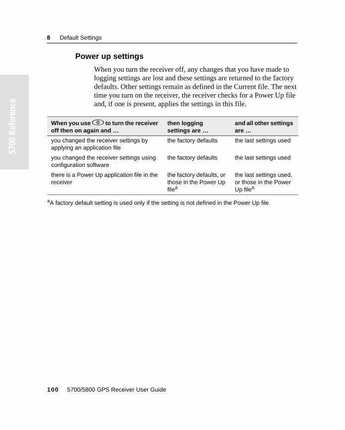
8 Default Settings
55700
Ref
eren
ce
8.4.2 Power up settings
When you turn the receiver off, any changes that you have made to logging settings are lost and these settings are returned to the factory defaults. Other settings remain as defined in the Current file. The next time you turn on the receiver, the receiver checks for a Power Up file and, if one is present, applies the settings in this file.
When you use p to turn the receiver off then on again and …
then logging settings are …
and all other settings are …
you changed the receiver settings by applying an application file
the factory defaults the last settings used
you changed the receiver settings using configuration software
the factory defaults the last settings used
there is a Power Up application file in the receiver
the factory defaults, or those in the Power Up filea
aA factory default setting is used only if the setting is not defined in the Power Up file.
the last settings used, or those in the Power Up filea
100 5700/5800 GPS Receiver User Guide
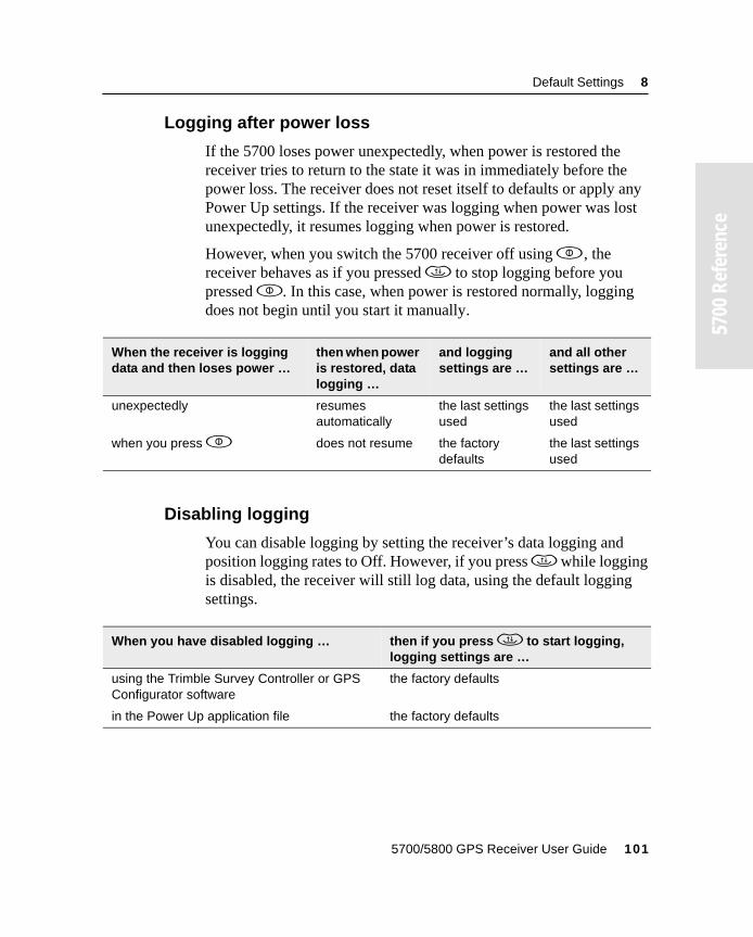
Default Settings 8
55700
Ref
eren
ce
8.4.3 Logging after power loss
If the 5700 loses power unexpectedly, when power is restored the receiver tries to return to the state it was in immediately before the power loss. The receiver does not reset itself to defaults or apply any Power Up settings. If the receiver was logging when power was lost unexpectedly, it resumes logging when power is restored.
However, when you switch the 5700 receiver off using p , the receiver behaves as if you pressed d to stop logging before you pressed p. In this case, when power is restored normally, logging does not begin until you start it manually.
8.4.4 Disabling logging
You can disable logging by setting the receiver’s data logging and position logging rates to Off. However, if you press d while logging is disabled, the receiver will still log data, using the default logging settings.
When the receiver is logging data and then loses power …
then when power is restored, data logging …
and logging settings are …
and all other settings are …
unexpectedly resumes automatically
the last settings used
the last settings used
when you press p does not resume the factory defaults
the last settings used
When you have disabled logging … then if you press d to start logging, logging settings are …
using the Trimble Survey Controller or GPS Configurator software
the factory defaults
in the Power Up application file the factory defaults
5700/5800 GPS Receiver User Guide 101
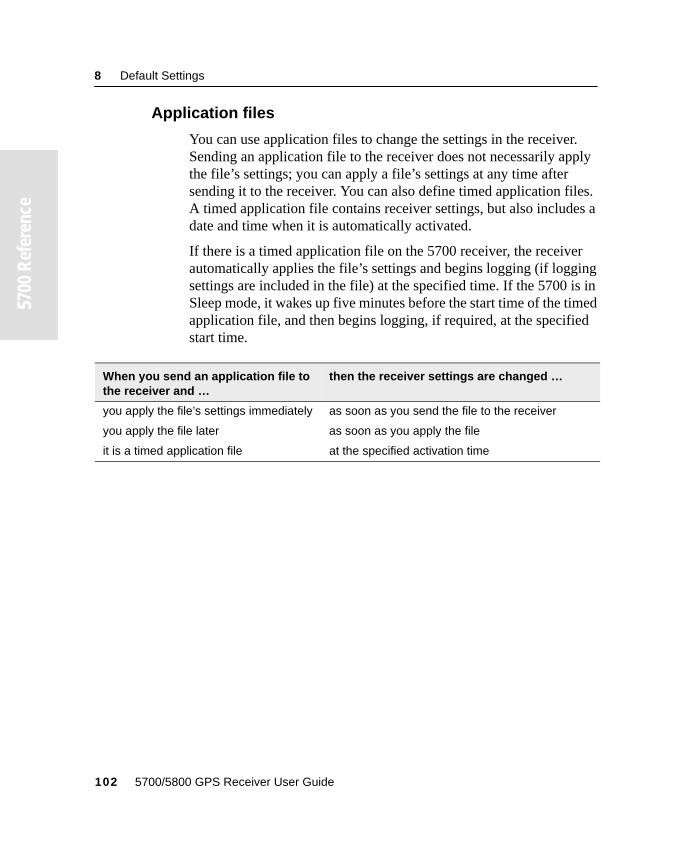
8 Default Settings
55700
Ref
eren
ce
8.4.5 Application files
You can use application files to change the settings in the receiver. Sending an application file to the receiver does not necessarily apply the file’s settings; you can apply a file’s settings at any time after sending it to the receiver. You can also define timed application files. A timed application file contains receiver settings, but also includes a date and time when it is automatically activated.
If there is a timed application file on the 5700 receiver, the receiver automatically applies the file’s settings and begins logging (if logging settings are included in the file) at the specified time. If the 5700 is in Sleep mode, it wakes up five minutes before the start time of the timed application file, and then begins logging, if required, at the specified start time.
When you send an application file to the receiver and …
then the receiver settings are changed …
you apply the file’s settings immediately as soon as you send the file to the receiver
you apply the file later as soon as you apply the file
it is a timed application file at the specified activation time
102 5700/5800 GPS Receiver User Guide
C H A P T E R
9
9 Cables and ConnectorsIn this chapter:
■ Introduction
■ Port 1, 2, and 3 connectors
■ Power/serial data cable
■ Event/PPS cable
■ GPS antennas and cables
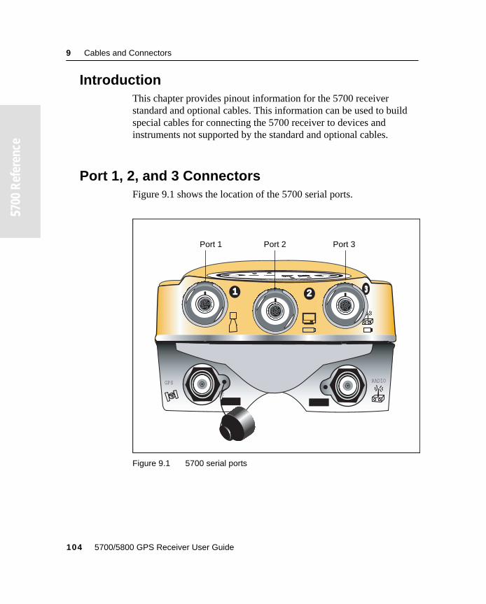
9 Cables and Connectors
55700
Ref
eren
ce
9.1 IntroductionThis chapter provides pinout information for the 5700 receiver standard and optional cables. This information can be used to build special cables for connecting the 5700 receiver to devices and instruments not supported by the standard and optional cables.
9.2 Port 1, 2, and 3 ConnectorsFigure 9.1 shows the location of the 5700 serial ports.
Figure 9.1 5700 serial ports
1 2
GPS RADIO
Port 1 Port 2 Port 3
104 5700/5800 GPS Receiver User Guide
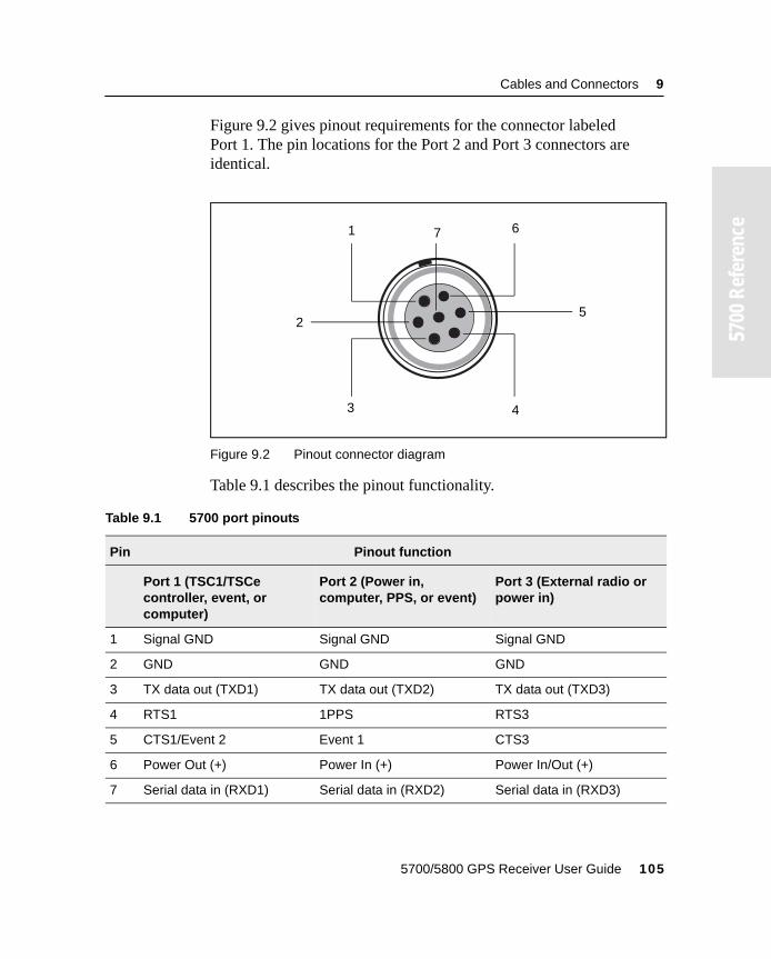
Cables and Connectors 9
55700
Ref
eren
ce
Figure 9.2 gives pinout requirements for the connector labeledPort 1. The pin locations for the Port 2 and Port 3 connectors are identical.
Figure 9.2 Pinout connector diagram
Table 9.1 describes the pinout functionality.
Table 9.1 5700 port pinouts
Pin Pinout function
Port 1 (TSC1/TSCe controller, event, or computer)
Port 2 (Power in, computer, PPS, or event)
Port 3 (External radio or power in)
1 Signal GND Signal GND Signal GND
2 GND GND GND
3 TX data out (TXD1) TX data out (TXD2) TX data out (TXD3)
4 RTS1 1PPS RTS3
5 CTS1/Event 2 Event 1 CTS3
6 Power Out (+) Power In (+) Power In/Out (+)
7 Serial data in (RXD1) Serial data in (RXD2) Serial data in (RXD3)
71
3
6
4
25
5700/5800 GPS Receiver User Guide 105
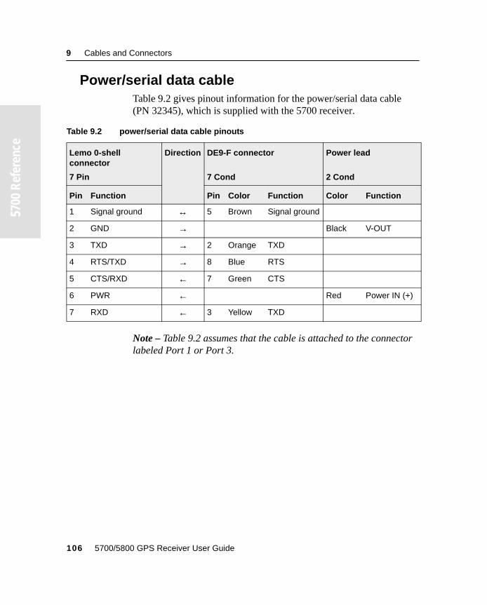
9 Cables and Connectors
55700
Ref
eren
ce
9.3 Power/serial data cableTable 9.2 gives pinout information for the power/serial data cable (PN 32345), which is supplied with the 5700 receiver.
Note – Table 9.2 assumes that the cable is attached to the connector labeled Port 1 or Port 3.
Table 9.2 power/serial data cable pinouts
Lemo 0-shell connector
7 Pin
Direction DE9-F connector
7 Cond
Power lead
2 Cond
Pin Function Pin Color Function Color Function
1 Signal ground ↔ 5 Brown Signal ground
2 GND → Black V-OUT
3 TXD → 2 Orange TXD
4 RTS/TXD → 8 Blue RTS
5 CTS/RXD ← 7 Green CTS
6 PWR ← Red Power IN (+)
7 RXD ← 3 Yellow TXD
106 5700/5800 GPS Receiver User Guide
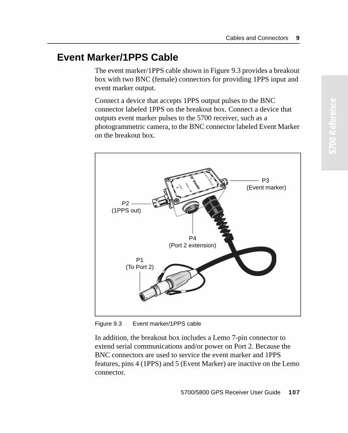
Cables and Connectors 9
55700
Ref
eren
ce
9.4 Event Marker/1PPS CableThe event marker/1PPS cable shown in Figure 9.3 provides a breakout box with two BNC (female) connectors for providing 1PPS input and event marker output.
Connect a device that accepts 1PPS output pulses to the BNC connector labeled 1PPS on the breakout box. Connect a device that outputs event marker pulses to the 5700 receiver, such as a photogrammetric camera, to the BNC connector labeled Event Marker on the breakout box.
Figure 9.3 Event marker/1PPS cable
In addition, the breakout box includes a Lemo 7-pin connector to extend serial communications and/or power on Port 2. Because the BNC connectors are used to service the event marker and 1PPS features, pins 4 (1PPS) and 5 (Event Marker) are inactive on the Lemo connector.
P4
P3
P1
P2
(Event marker)
(1PPS out)
(To Port 2)
(Port 2 extension)
5700/5800 GPS Receiver User Guide 107
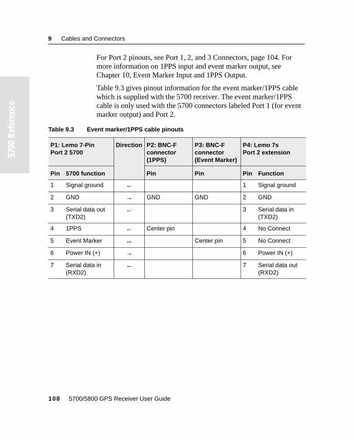
9 Cables and Connectors
55700
Ref
eren
ce
For Port 2 pinouts, see Port 1, 2, and 3 Connectors, page 104. For more information on 1PPS input and event marker output, see Chapter 10, Event Marker Input and 1PPS Output.
Table 9.3 gives pinout information for the event marker/1PPS cable which is supplied with the 5700 receiver. The event marker/1PPS cable is only used with the 5700 connectors labeled Port 1 (for event marker output) and Port 2.
Table 9.3 Event marker/1PPS cable pinouts
P1: Lemo 7-Pin Port 2 5700
Direction P2: BNC-F connector (1PPS)
P3: BNC-F connector (Event Marker)
P4: Lemo 7s Port 2 extension
Pin 5700 function Pin Pin Pin Function
1 Signal ground ← 1 Signal ground
2 GND → GND GND 2 GND
3 Serial data out (TXD2)
← 3 Serial data in (TXD2)
4 1PPS ← Center pin 4 No Connect
5 Event Marker ↔ Center pin 5 No Connect
6 Power IN (+) → 6 Power IN (+)
7 Serial data in (RXD2)
← 7 Serial data out (RXD2)
108 5700/5800 GPS Receiver User Guide
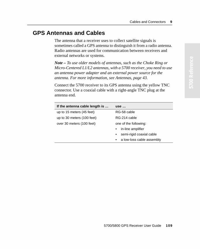
Cables and Connectors 9
55700
Ref
eren
ce
9.5 GPS Antennas and CablesThe antenna that a receiver uses to collect satellite signals is sometimes called a GPS antenna to distinguish it from a radio antenna. Radio antennas are used for communication between receivers and external networks or systems.
Note – To use older models of antennas, such as the Choke Ring or Micro-Centered L1/L2 antennas, with a 5700 receiver, you need to use an antenna power adapter and an external power source for the antenna. For more information, see Antennas, page 43.
Connect the 5700 receiver to its GPS antenna using the yellow TNC connector. Use a coaxial cable with a right-angle TNC plug at the antenna end.
If the antenna cable length is … use …
up to 15 meters (45 feet) RG-58 cable
up to 30 meters (100 feet) RG-214 cable
over 30 meters (100 feet) one of the following:
• in-line amplifier
• semi-rigid coaxial cable
• a low-loss cable assembly
5700/5800 GPS Receiver User Guide 109

9 Cables and Connectors
55700
Ref
eren
ce
110 5700/5800 GPS Receiver User Guide

C H A P T E R
10
10 Event Marker Input and 1PPS OutputIn this chapter:■ Introduction
■ Event marker input
■ 1PPS output
10 Event Marker Input and 1PPS Output
55700
Ref
eren
ce
10.1IntroductionThe 5700 receiver can accept event marker input on Port 1 and Port 2, and can generate 1PPS output on Port 2.
10.2Event Marker InputEvent marker input is used to log a precise GPS time tag whenever an externally generated pulse, such as one generated at the time of the shutter closing from a photogrammetric camera, is received.
The event is triggered when the source pulse voltage transitions between 1.0 VDC and 2.0 VDC in less than 100 nsec. Trimble recommends that you use TTL level inputs. You can configure the receiver to recognize either a positive (rising) or negative (falling) voltage as the leading edge of a pulse. The accuracy of the associated time tag recorded for an event is determined by the GPS accuracy (typically less than 1 µsec.).
The 5700 receiver records each event in the current data file. This record includes the port on which the event was received.
10.2.1 Enabling and configuring event marker input
To enable or configure the event marker input function, you need either GPS Configurator or Configuration Toolbox.
In real time
You can use GPS Configurator to configure a Trimble GPS receiver connected to your office computer. For more information, see GPS Configurator Software, page 80, or refer to the GPS Configurator Help.
To enable event marker input:
1. Connect the computer to the 5700 receiver.
2. Press p to power on the 5700 receiver.
112 5700/5800 GPS Receiver User Guide
Event Marker Input and 1PPS Output 10
55700
Ref
eren
ce
3. To start GPS Configurator, click , then select Programs / Trimble / GPS Configurator / GPS Configurator.
The GPS Configurator dialog appears and the software automatically connects to the 5700 receiver.
4. In the General tab, select the Event marker check box.
5. Select the appropriate option, Positive slope or Negative slope, depending on the type of pulse the external device uses.
6. Click Apply.
GPS Configurator sends the new configuration information to the 5700 receiver, and the receiver starts to accept event marker input.
7. Click OK to exit GPS Configurator.
The software disconnects from the 5700 receiver.
5700/5800 GPS Receiver User Guide 113
10 Event Marker Input and 1PPS Output
55700
Ref
eren
ce
Using an application file
Configuration Toolbox lets you create an application file containing the appropriate configuration instructions for event marker input. You can then transfer that file to the 5700 to enable event marker input.
For more information, see Configuration Toolbox Software, page 82, or refer to the Configuration Toolbox Help.
To create an application file that enables event marker input:
1. Connect the computer to the 5700 receiver.
2. Press p to power on the 5700 receiver.
3. To start Configuration Toolbox, click , then select Programs / Trimble / Configuration Toolbox / Configuration Toolbox.
The main Configuration Toolbox window appears.
4. Select File / New / 5700 to display the Configuration File dialog.
5. From the Available list select Device, then click Add.
114 5700/5800 GPS Receiver User Guide
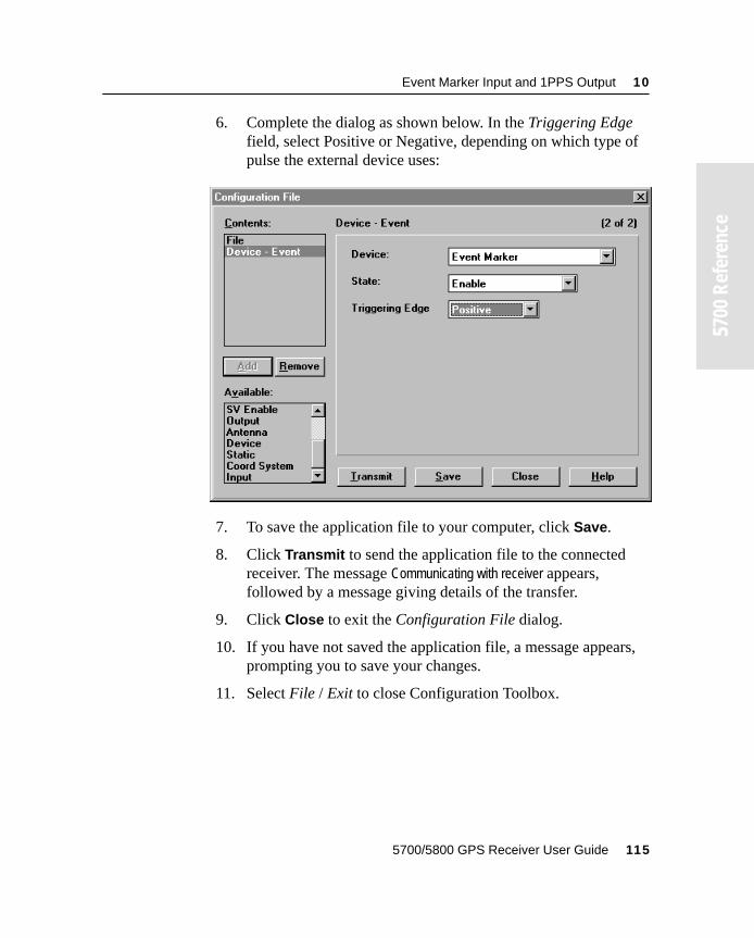
Event Marker Input and 1PPS Output 10
55700
Ref
eren
ce
6. Complete the dialog as shown below. In the Triggering Edge field, select Positive or Negative, depending on which type of pulse the external device uses:
7. To save the application file to your computer, click Save.
8. Click Transmit to send the application file to the connected receiver. The message Communicating with receiver appears, followed by a message giving details of the transfer.
9. Click Close to exit the Configuration File dialog.
10. If you have not saved the application file, a message appears, prompting you to save your changes.
11. Select File / Exit to close Configuration Toolbox.
5700/5800 GPS Receiver User Guide 115
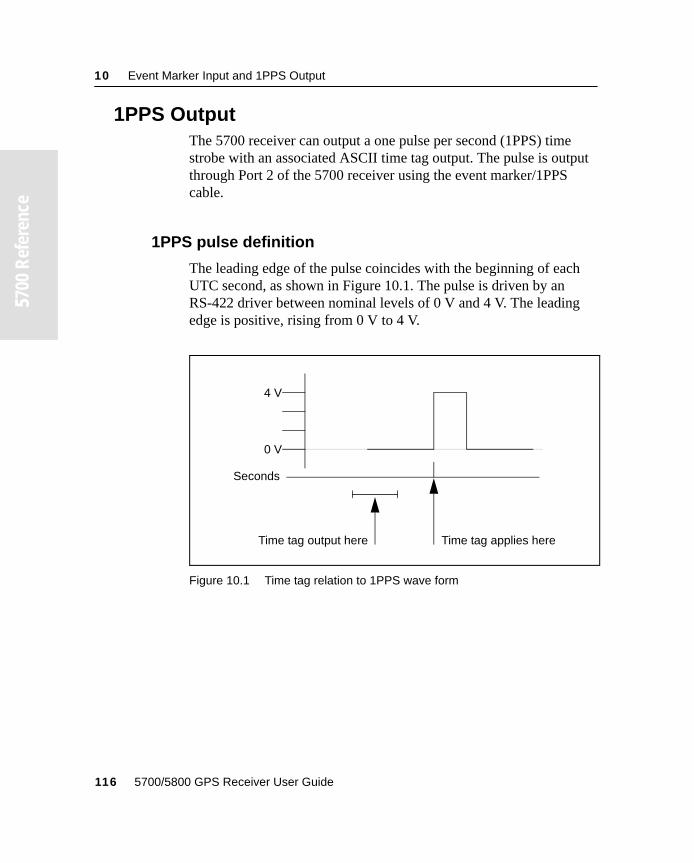
10 Event Marker Input and 1PPS Output
55700
Ref
eren
ce
10.31PPS OutputThe 5700 receiver can output a one pulse per second (1PPS) time strobe with an associated ASCII time tag output. The pulse is output through Port 2 of the 5700 receiver using the event marker/1PPS cable.
10.3.1 1PPS pulse definition
The leading edge of the pulse coincides with the beginning of each UTC second, as shown in Figure 10.1. The pulse is driven by an RS-422 driver between nominal levels of 0 V and 4 V. The leading edge is positive, rising from 0 V to 4 V.
Figure 10.1 Time tag relation to 1PPS wave form
0 V
4 V
Seconds
Time tag output here Time tag applies here
116 5700/5800 GPS Receiver User Guide
Event Marker Input and 1PPS Output 10
55700
Ref
eren
ce
The pulse is approximately 8 µsec wide, with rise and fall times of about 100 nsec. Resolution is approximately 40 nsec, but several external factors limit accuracy to approximately ±1 µsec:
• Position errors, especially with user-entered reference. Each meter of error can result in 3 nsec of error in the 1PPS pulse.
• Antenna cable length. Each meter of cable adds a delay of about 2 nsec to satellite signals, and a corresponding delay in the 1PPS pulse.
10.3.2 ASCII time tag definition
Each time tag is output about 0.5 second before the corresponding pulse, as shown in Figure 10.1. Time tags are in ASCII format on a user-selected serial port. The format of a time tag is:
UTC yy.mm.dd hh:mm:ss ab
Where:
• UTC is fixed text.
• yy.mm.dd is the year, month, and date.
• hh:mm:ss is the hour (on a 24-hour clock), minute, and second. The time is in UTC, not GPS time.
• a is the position-fix type:
1 = 2D Position Fix for E,N only2 = 3D Position Fix3 = Single SV Clock-only fix4 = Automatic Mode5 = Reference Station Position6 = Two-Dimensional with Fixed Clock7 = Overdetermined solution for Clock-only
• b is the number of satellites being tracked: 1 to 9, “:” (for 10), “;” (for 11), or “<” (for 12).
• Each time tag is terminated by a carriage return, line feed sequence.
5700/5800 GPS Receiver User Guide 117
10 Event Marker Input and 1PPS Output
55700
Ref
eren
ce
A typical printout looks like this:
UTC 93.12.21 20:21:16 56UTC 93.12.21 20:21:17 56UTC 93.12.21 20:21:18 56
If a and b are ??, the time is based on the receiver clock because the receiver is not tracking satellites. The receiver clock is less accurate than time readings extracted from satellite signals.
10.3.3 Enabling and configuring 1PPS output
To enable or configure the 1PPS output function, you need either GPS Configurator or Configuration Toolbox.
In real time
You can use GPS Configurator to configure a Trimble GPS receiver connected to your office computer. For more information, see GPS Configurator Software, page 80, or refer to the GPS Configurator Help.
To enable 1PPS output:
1. Connect the computer to the 5700 receiver.
2. Power on the 5700 receiver.
3. To start GPS Configurator, click , then select Programs / Trimble / GPS Configurator / GPS Configurator.
The GPS Configurator dialog appears and the software automatically connects to the 5700 receiver.
4. Select the Serial outputs tab.
5. Select the 1PPS (port 2 only) check box.
6. If you want ASCII time tags enabled, select the check box and choose an output port.
118 5700/5800 GPS Receiver User Guide
Event Marker Input and 1PPS Output 10
55700
Ref
eren
ce
7. Click Apply.
GPS Configurator sends the new configuration information to the 5700 receiver, and the receiver starts to generate 1PPS output on Port 2.
8. Click OK to exit GPS Configurator.
The software disconnects from the 5700 receiver.
Using an application file
Configuration Toolbox lets you create an application file containing the appropriate configuration instructions for 1PPS output. You can then transfer that file to the 5700 to enable 1PPS output.
For more information, see Configuration Toolbox Software, page 82, or refer to the Configuration Toolbox Help.
To create an application file for 1PPS output:
1. Connect the computer to the 5700 receiver.
2. Power on the 5700 receiver.
3. To start Configuration Toolbox, click , then select Programs / Trimble / Configuration Toolbox / Configuration Toolbox.
The main Configuration Toolbox window appears.
4. Select File / New / 5700 to display the Configuration File dialog.
5. From the Available list, select Device, and then click Add.
6. From the Device field, select 1 Pulse Per Second.
5700/5800 GPS Receiver User Guide 119
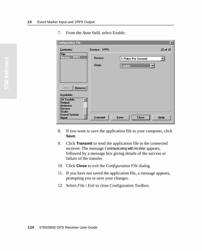
10 Event Marker Input and 1PPS Output
55700
Ref
eren
ce
7. From the State field, select Enable:
8. If you want to save the application file to your computer, click Save.
9. Click Transmit to send the application file to the connected receiver. The message Communicating with receiver appears, followed by a message box giving details of the success or failure of the transfer.
10. Click Close to exit the Configuration File dialog.
11. If you have not saved the application file, a message appears, prompting you to save your changes.
12. Select File / Exit to close Configuration Toolbox.
120 5700/5800 GPS Receiver User Guide

S E C T I O N
II
II5800 GPS RECEIVER

C H A P T E R
11
11 OverviewIn this chapter:
■ Introduction
■ Features
■ Use and Care
■ COCOM Limits
11 Overview
55800
Ope
ratio
n
11.1IntroductionThis chapter introduces the 5800 receiver which is designed for GPS surveying applications. The 5800 receiver incorporates a GPS antenna, receiver, internal radio, and battery in a rugged light-weight unit that is ideally suited as an all-on-the-pole RTK rover. Three LEDs allow you to monitor the satellite tracking, radio reception, and power. Bluetooth technology provides cable-free communications between receiver and controller. The 5800 receiver provides 24 total channels of L1/L2 satellite tracking, and supports logging of raw GPS observables to the handheld controller for post-processed applications.
The 5800 is available as a standalone rover or as part of the GPS Total Station® 5700 system, offering maximum versatility in the system configuration to meet your specific requirements.
11.2Features The receiver provides the following features:
• Centimeter-accuracy, real-time positioning with RTK/OTF data, up to 10 Hz position updates
• Submeter-accuracy, real-time positioning using pseudorange corrections
• Adaptive dual-frequency RTK engine
• WAAS/EGNOS capability
• Automatic OTF (on-the-fly) initialization while moving
124 5700/5800 GPS Receiver User Guide
Overview 11
55800
Ope
ratio
n
• Single lithium-ion rechargeable battery
• Cable-free Bluetooth communications with the Trimble Attachable Control Unit (ACU), or TSCe with Bluecap module
• Two RS-232 serial ports for:
– NMEA output
– RTCM SC-104 input
– Trimble Format (CMR & CMR Plus) input
• One TNC port for connecting to a radio antenna
5700/5800 GPS Receiver User Guide 125
11 Overview
55800
Ope
ratio
n
11.3Use and CareThe 5800 receiver is designed to withstand the rough treatment that typically occurs in the field. However, the receiver is a high-precision electronic instrument and should be treated with reasonable care.
C Warning – Operating or storing the 5800 receiver outside the specified temperature range can damage it. For details, see Physical specifications, page 166.
High-power signals from a nearby radio or radar transmitter can overwhelm the receiver circuits. This does not harm the instrument, but it can prevent the receiver electronics from functioning correctly. Avoid using the receiver within 400 meters of powerful radar, television, or other transmitters. Low-power transmitters, such as those used in cell phones and two-way radios, do not normally interfere with 5800 receiver operations.
11.4COCOM LimitsThe U.S. Department of Commerce requires that all exportable GPS products contain performance limitations so that they cannot be used in a manner that could threaten the security of the United States. The following limitations are implemented on the 5800 receiver.
Immediate access to satellite measurements and navigation results is disabled when the receiver’s velocity is computed to be greater than 1000 knots, or its altitude is computed to be above 18,000 meters. The receiver continuously resets until the COCOM situation is cleared.
126 5700/5800 GPS Receiver User Guide
C H A P T E R
12
12 Setting up the ReceiverIn this chapter:
■ Introduction
■ Parts of the receiver
■ Setup guidelines
■ Pole-mounted setup
■ Other system components
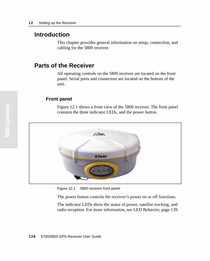
12 Setting up the Receiver
55800
Ope
ratio
n
12.1IntroductionThis chapter provides general information on setup, connection, and cabling for the 5800 receiver.
12.2Parts of the ReceiverAll operating controls on the 5800 receiver are located on the front panel. Serial ports and connectors are located on the bottom of the unit.
12.2.1 Front panel
Figure 12.1 shows a front view of the 5800 receiver. The front panel contains the three indicator LEDs, and the power button.
Figure 12.1 5800 receiver front panel
The power button controls the receiver’s power on or off functions.
The indicator LEDs show the status of power, satellite tracking, and radio reception. For more information, see LED Behavior, page 139.
128 5700/5800 GPS Receiver User Guide
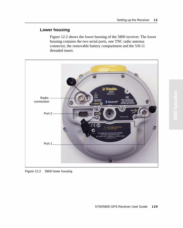
Setting up the Receiver 12
55800
Ope
ratio
n
12.2.2 Lower housing
Figure 12.2 shows the lower housing of the 5800 receiver. The lower housing contains the two serial ports, one TNC radio antenna connector, the removable battery compartment and the 5/8-11 threaded insert.
Figure 12.2 5800 lower housing
Port 1
Port 2
Radio connection
5700/5800 GPS Receiver User Guide 129
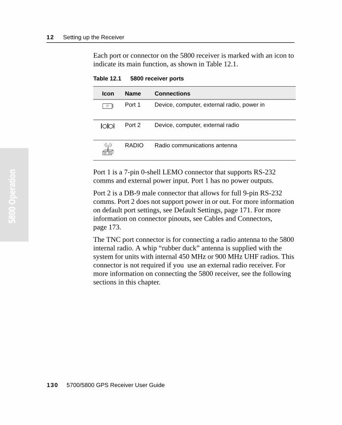
12 Setting up the Receiver
55800
Ope
ratio
n
Each port or connector on the 5800 receiver is marked with an icon to indicate its main function, as shown in Table 12.1.
Port 1 is a 7-pin 0-shell LEMO connector that supports RS-232 comms and external power input. Port 1 has no power outputs.
Port 2 is a DB-9 male connector that allows for full 9-pin RS-232 comms. Port 2 does not support power in or out. For more information on default port settings, see Default Settings, page 171. For more information on connector pinouts, see Cables and Connectors, page 173.
The TNC port connector is for connecting a radio antenna to the 5800 internal radio. A whip “rubber duck” antenna is supplied with the system for units with internal 450 MHz or 900 MHz UHF radios. This connector is not required if you use an external radio receiver. For more information on connecting the 5800 receiver, see the following sections in this chapter.
Table 12.1 5800 receiver ports
Icon Name Connections
Port 1 Device, computer, external radio, power in
Port 2 Device, computer, external radio
RADIO Radio communications antenna
130 5700/5800 GPS Receiver User Guide
Setting up the Receiver 12
55800
Ope
ratio
n
12.3 Setup Guidelines
Consider the following guidelines when setting up the 5800 receiver.
12.3.1 Environmental conditions
Although the 5800 receiver has a waterproof housing, reasonable care should be taken to protect the unit. Avoid exposure to extreme environmental conditions, including:
• Water
• Heat greater than 65°C (149°F)
• Cold less than –40°C (–40°F)
• Corrosive fluids and gases
12.3.2 Sources of electrical interference
Avoid the following sources of electrical and magnetic noise:
• Gasoline engines (spark plugs)
• Televisions and PC monitors
• Alternators and generators
• Electric motors
• Equipment with DC-to-AC converters
• Fluorescent lights
• Switching power supplies
5700/5800 GPS Receiver User Guide 131
12 Setting up the Receiver
55800
Ope
ratio
n
12.3.3 General guidelines
The following guidelines apply whenever you set up your receiver for operation:
• When plugging in a Lemo cable, make sure that the red dots on the receiver port and the cable connector line up. Never use force to plug cables in, as this may damage the connector pins.
• When disconnecting a Lemo cable, grasp the cable by the sliding collar or lanyard and pull the cable connector straight out of the port. Do not twist the connector or pull on the cable itself.
• To securely connect a TNC cable, align the cable connector with the receiver receptacle, then thread the cable connector onto the receptacle until it is snug.
• To insert the internal battery place the battery in the battery compartment, ensuring that the contact points are in the correct position to align with the contacts in the receiver. Slide the battery and compartment as a unit upward into the receiver until the battery compartment latches are locked into position.
132 5700/5800 GPS Receiver User Guide
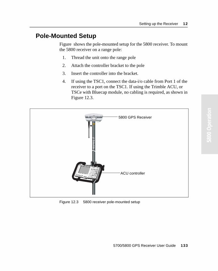
Setting up the Receiver 12
55800
Ope
ratio
n
12.4Pole-Mounted SetupFigure shows the pole-mounted setup for the 5800 receiver. To mount the 5800 receiver on a range pole:
1. Thread the unit onto the range pole
2. Attach the controller bracket to the pole
3. Insert the controller into the bracket.
4. If using the TSC1, connect the data-i/o cable from Port 1 of the receiver to a port on the TSC1. If using the Trimble ACU, or TSCe with Bluecap module, no cabling is required, as shown in Figure 12.3.
Figure 12.3 5800 receiver pole-mounted setup
F
F
5800 GPS Receiver
ACU controller
5700/5800 GPS Receiver User Guide 133
12 Setting up the Receiver
55800
Ope
ratio
n
12.5Other System ComponentsThis section describes optional components that you can use with the 5800 receiver.
12.5.1 Radios
Radios are the most common data link for Real-Time Kinematic (RTK) surveying. The 5800 receiver is available with an optional internal radio in either the 450 or 900 MHz UHF band. You can also connect an external radio to either serial port, whether the internal radio is installed or not.
The 5800 receiver supports the following Trimble base radios with the internal 450 MHz or 900 MHz UHF radios:
• TRIMMARK 3
• TRIMMARK IIe
• TRIMTALK 450S
• SiteNet 450
• SiteNet 900
134 5700/5800 GPS Receiver User Guide
Setting up the Receiver 12
55800
Ope
ratio
n
Internal Radio Setup
You can configure the 5800 receiver’s optional internal radio using any of the following software:
• GPS Configurator
• WinFlash
• Trimble Survey Controller
For more information, refer to the GPS Configurator Help, the WinFlash Help, or the Trimble Survey Controller User Guide.
By default, the internal radio has only a few “test” frequencies installed at the factory. Use WinFlash to program your licensed frequencies prior to using the receiver. For more information, see Adding frequencies for the 450 MHz internal radio, page 161.
12.5.2 Cellular modems and external radios
You can use a cellular modem or external radio instead of the internal radio as your data communications link.
To connect a cellular modem to a 5800 receiver you need the following:
• 5800 Receiver
• A cellular modem, or a cell phone that can transmit and receive data
• Serial (cell phone to DB9) cable (supplied with the cellular modem or phone)
Note – For more information, refer to the document Using Cellular and CDPD Modems for RTK, which is available from the Trimble website.
• Port 2 of the 5800 supports full RS-232 protocol, and should function properly with most cellular phone cables. Some cellular units may require custom cabling.
5700/5800 GPS Receiver User Guide 135
12 Setting up the Receiver
55800
Ope
ratio
n
For more information on using a cellular modem as a data link, refer to the Trimble Survey Controller User Guide.
To connect an external radio modem to a 5800 receiver you need the following:
• 5800 Receiver
• An external radio capable of receiving and decoding Trimble data packets
• Serial cable for either Port 1 or Port 2 of the 5800, as supplied by the radio manufacturer.
• Radio mount for the range pole.
136 5700/5800 GPS Receiver User Guide

C H A P T E R
13
13 General OperationIn this chapter:
■ Introduction
■ Button functions
■ LED behavior
■ Starting and stopping the receiver
■ Logging data
■ Resetting to defaults
■ Batteries and power
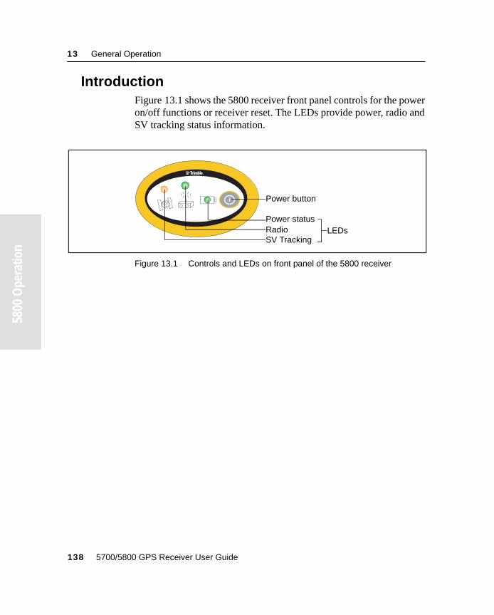
13 General Operation
55800
Ope
ratio
n
13.1IntroductionFigure 13.1 shows the 5800 receiver front panel controls for the power on/off functions or receiver reset. The LEDs provide power, radio and SV tracking status information.
Figure 13.1 Controls and LEDs on front panel of the 5800 receiver
F
Power button
SV TrackingRadioPower status
LEDs
138 5700/5800 GPS Receiver User Guide
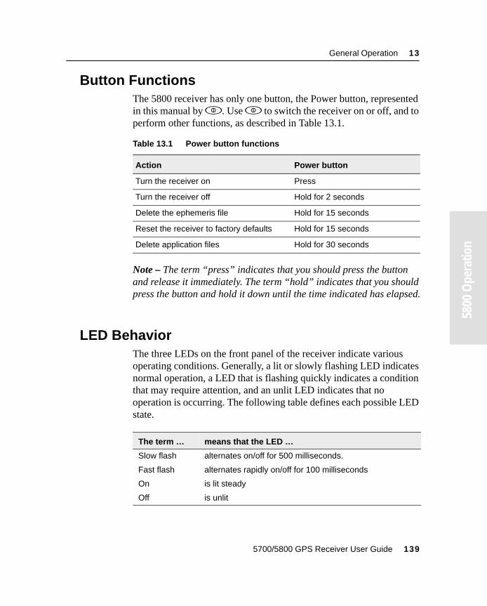
General Operation 13
55800
Ope
ratio
n
13.2Button FunctionsThe 5800 receiver has only one button, the Power button, represented in this manual by p. Use p to switch the receiver on or off, and to perform other functions, as described in Table 13.1.
Note – The term “press” indicates that you should press the button and release it immediately. The term “hold” indicates that you should press the button and hold it down until the time indicated has elapsed.
13.3LED BehaviorThe three LEDs on the front panel of the receiver indicate various operating conditions. Generally, a lit or slowly flashing LED indicates normal operation, a LED that is flashing quickly indicates a condition that may require attention, and an unlit LED indicates that no operation is occurring. The following table defines each possible LED state.
Table 13.1 Power button functions
Action Power button
Turn the receiver on Press
Turn the receiver off Hold for 2 seconds
Delete the ephemeris file Hold for 15 seconds
Reset the receiver to factory defaults Hold for 15 seconds
Delete application files Hold for 30 seconds
The term … means that the LED …
Slow flash alternates on/off for 500 milliseconds.
Fast flash alternates rapidly on/off for 100 milliseconds
On is lit steady
Off is unlit
5700/5800 GPS Receiver User Guide 139
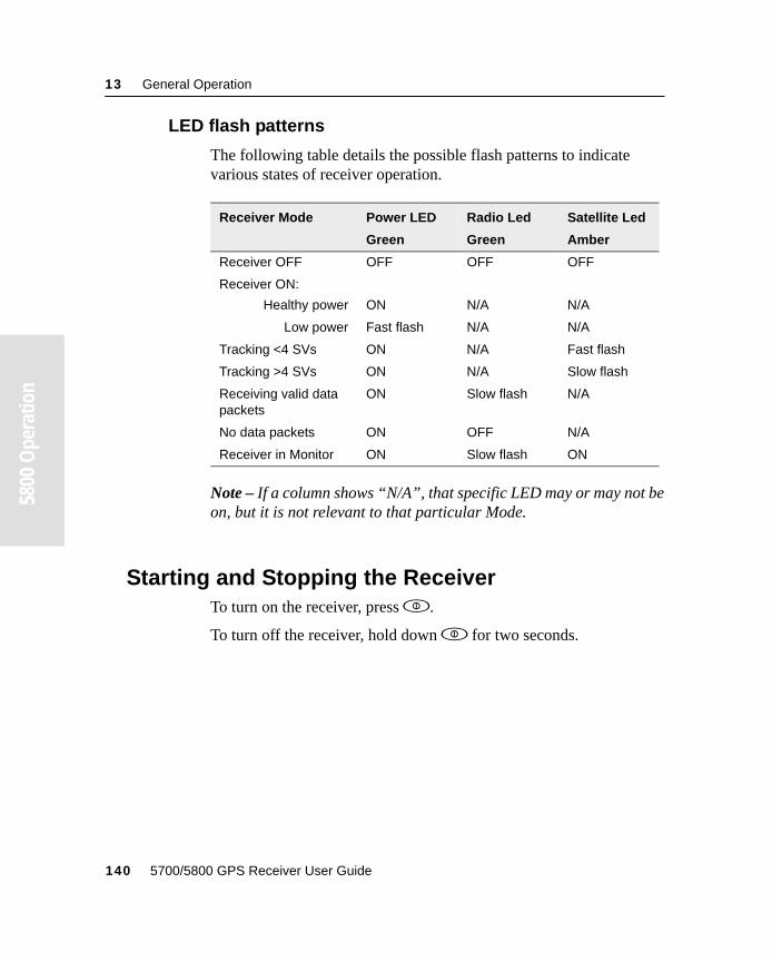
13 General Operation
55800
Ope
ratio
n
13.3.1 LED flash patterns
The following table details the possible flash patterns to indicate various states of receiver operation.
Note – If a column shows “N/A”, that specific LED may or may not be on, but it is not relevant to that particular Mode.
13.4Starting and Stopping the ReceiverTo turn on the receiver, press p.
To turn off the receiver, hold down p for two seconds.
Receiver Mode Power LED
Green
Radio Led
Green
Satellite Led
Amber
Receiver OFF OFF OFF OFF
Receiver ON:
Healthy power ON N/A N/A
Low power Fast flash N/A N/A
Tracking <4 SVs ON N/A Fast flash
Tracking >4 SVs ON N/A Slow flash
Receiving valid data packets
ON Slow flash N/A
No data packets ON OFF N/A
Receiver in Monitor ON Slow flash ON
140 5700/5800 GPS Receiver User Guide
General Operation 13
55800
Ope
ratio
n
13.5Logging DataAs the 5800 receiver does not contain internal memory, you can only log data to the controller.
13.5.1 Logging to a Trimble controller
When the 5800 receiver is connected to a Trimble controller, you can log GPS data from the receiver to the controller, or to a PC card inserted in the controller. When you use a Trimble controller, you do not use the receiver’s controls. Instead, you use the controller functions to set logging options, specify filenames, and control when logging occurs.
Data is stored in job files, which can be transferred to your office computer using Trimble’s Data Transfer utility.
For more information on logging data from a receiver using a Trimble controller refer to the user guide for your particular controller.
13.6Resetting to DefaultsTo reset the 5800 receiver to its factory default settings, hold down p for at least 15 seconds.
For more information, see Chapter 17, Default Settings.
13.7Batteries and PowerThe 5800 receiver can be powered either by its internal battery or by an external power source connected to Port 1. Typically, one internal 1.8 ampere-hour battery provides approximately 5.5 hours of operation during an RTK survey using the internal radio.
5700/5800 GPS Receiver User Guide 141
13 General Operation
55800
Ope
ratio
n
If an external power source is connected to Port 1 it is used in preference to the internal battery. When there is no external power source connected, or if the external power supply fails, the internal battery is used.
The 5800 Rover system includes two rechargeable lithium-ion batteries, and a dual battery charger. The two batteries charge sequentially and take approximately four hours each to fully charge.
13.7.1 Battery charging and storage
Note – All battery types discharge over time when they are not being used. Batteries also discharge faster in colder temperatures. If a lithium-ion battery is to be stored for long periods of time, make sure it is fully charged before storing and re-charged at least every three months.
To protect the battery from deep discharge (5 volts or less), the 5800 receiver is designed to stop drawing power when the battery pack discharges to 5.9 volts. The unit will shut down with no damage to receiver or battery.
A battery that has reached the deep discharge level cannot be recharged and must be replaced. The following recommendations provide optimal performance and extend the life of your batteries:
• Fully charge all new batteries prior to use.
• Do not allow the batteries to discharge below 5 volts.
• Keep all batteries on continuous charge when not in use. Batteries may be kept on charge indefinitely without damage to the receiver or batteries.
• Do not store batteries in the external charger unless power is applied.
If you must store the batteries, fully charge them before storing and then recharge them at least every three months.
142 5700/5800 GPS Receiver User Guide
General Operation 13
55800
Ope
ratio
n
13.7.2 Power output
The 5800 receiver does not output power from either of its 2 ports.
13.7.3 Firmware
A receiver’s firmware is the program inside the receiver that controls receiver operations and hardware. You can upgrade the firmware for the 5800 receiver using the WinFlash utility provided on the 5700/5800 GPS Receiver CD.
For more information, see WinFlash Software, page 159.
C Warning – Upgrading the firmware deletes all application files on the 5800 receiver.
5700/5800 GPS Receiver User Guide 143
13 General Operation
55800
Ope
ratio
n
144 5700/5800 GPS Receiver User Guide
C H A P T E R
14
14 ConfigurationIn this chapter:
■ Introduction
■ Configuring the receiver in real time
■ Configuring the receiver using application files
■ Application files
14 Configuration
55800
Ope
ratio
n
14.1IntroductionThe 5800 receiver has no controls for changing settings. It can only be configured using external software such as GPS Configurator, WinFlash, Configuration Toolbox, or Trimble Survey Controller.
There are two ways to configure the 5800 receiver. You can:
• configure the receiver in real time
• apply the settings in an application file
This chapter provides a brief overview of each of these methods and describes the contents and use of application files.
14.2Configuring the Receiver in Real TimeGPS Configurator, Configuration Toolbox, and Trimble Survey Controller all support real-time configuration of the 5800 receiver.
When you configure the receiver in real time, you use one of these software applications to specify which settings you want to change. When you apply the changes, the receiver settings change immediately.
Any changes that you apply to the receiver are reflected in the Current application file, which is always present in the receiver. The Current application file always records the most recent configuration, so if you apply further changes (either in real time or using an application file) the Current file is updated and there is no record of the changes that you applied originally.
For more information on configuring the receiver in real time, see Chapter 15, Software Utilities.
146 5700/5800 GPS Receiver User Guide
Configuration 14
55800
Ope
ratio
n
14.3Configuring the Receiver Using Application FilesAn application file contains information for configuring a receiver. To configure a receiver using an application file, you need to create the application file, transfer it to the receiver, and then apply the file’s settings. Use the Configuration Toolbox software to perform all these tasks.
For more information on applying application files, see Chapter 15, Software Utilities.
14.4Application FilesAn application file is organized into records. Each record stores configuration information for a particular area of receiver operation. Application files can include the following records:
• File Storage
• General Controls
• Serial Port Baud/Format
• Reference Position
• Logging Rate
• SV Enable/Disable
• Output Message
• Antenna
• Device Control
• Static/Kinematic
• Input Message
5700/5800 GPS Receiver User Guide 147
14 Configuration
55800
Ope
ratio
n
An application file does not have to contain all of these records. When you apply an application file, any option that is not included in the records in the file remains at its current setting. For example, if you apply an application file that only specifies the elevation mask to use, all other settings remain as they were before the application file was applied.
You can store up to twenty different application files in the receiver. You can apply an application file’s settings at the time it is transferred to the receiver, or at any time afterwards.
14.4.1 Special application files
The 5800 receiver has three special application files, which control important aspects of the receiver’s configuration.
Default application file
The Default application file (Default.cfg) contains the original receiver configuration, and cannot be changed. This file configures the receiver after it is reset. You can reset the receiver by holding down p for at least 15 seconds, or by using the reset option in GPS Configurator.
For more information on the default receiver settings, see Default Settings, page 169.
Although you cannot change or delete the Default application file, you can use a Power Up application file to override any or all of the default settings.
148 5700/5800 GPS Receiver User Guide
Configuration 14
55800
Ope
ratio
n
Current application file
The Current application file (Current.cfg) reflects the current receiver configuration. Whenever you change the receiver’s configuration, either in real time or by applying an application file, the Current file changes to match the new configuration.
You cannot delete the Current file or change it directly, but every change to the receiver’s current configuration is applied to the Current file as well.
When you switch off the receiver then turn it on again, all the settings from the Current application file are applied, so you do not lose any changes that you have made. The only exceptions are the following logging parameters:
• Logging rate
• Position rate
• Elevation mask
These parameters are always reset to the factory default values whenever the receiver is switched off.
Power Up application file
The Power Up application file (Power_up.cfg) is used to set the receiver to a specific configuration any time the unit is powered up.
You can specify that the receiver is reset to defaults before the Power Up settings are applied. This ensures that restarting the receiver always resets it to factory defaults prior to applying the Power_up application file.
Alternatively, you can specify that the Power Up settings are applied immediately after the Current application file’s settings have been applied. Restarting the receiver results in a configuration that uses your default settings for the options you define in the Power Up file, but the current settings for all other options.
5700/5800 GPS Receiver User Guide 149
14 Configuration
55800
Ope
ratio
n
By default, there is no Power Up application file on the receiver. If you want to use a Power Up application file, you need to create an application file in Configuration Toolbox and make sure that the As auto power up file option is selected in the File page. When you transfer this file to the receiver, it is transferred with the name Power_up.cfg, and becomes the new Power Up file.
The Power Up file is the only special application file that you can overwrite or delete from the receiver.
14.4.2 Applying application files
An application file’s settings do not affect the receiver’s configuration until you apply the application file. You can do this at the same time that you save the file. Alternatively, you can save the file on the computer or in the receiver, then open it later and apply its settings.
14.4.3 Storing application files
You can store application files that you create in Configuration Toolbox on both your receiver and computer. Each file can, for example, represent a different user sharing the same receiver, or a particular mode of operation or survey style. Saving application files on your computer as well as in your receiver is optional, but it is useful because:
• it gives you a permanent copy of the settings you have sent to a receiver, for audit or your own reference
• you can use the same file to configure multiple receivers identically
• you can use an existing application file as a template for creating other application files with similar settings
150 5700/5800 GPS Receiver User Guide
Configuration 14
55800
Ope
ratio
n
14.4.4 Naming application files
The filename that you use to store the application file in the computer and the name under which the file is stored in the receiver are always the same. This makes recognizing and keeping track of your application files easier. If you change the name of the file on the receiver, this changes the filename used to store the application file on your computer. Similarly, if you change the filename on the computer, the name of the file in the receiver will change.
5700/5800 GPS Receiver User Guide 151

14 Configuration
55800
Ope
ratio
n
152 5700/5800 GPS Receiver User Guide

C H A P T E R
15
15 Software UtilitiesIn this chapter:
■ Introduction
■ GPS Configurator software
■ Configuration Toolbox software
■ WinFlash software
15 Software Utilities
55800
Ope
ratio
n
15.1IntroductionThis chapter provides information on the software utilities that you can use with the 5800 receiver.
15.2GPS Configurator SoftwareGPS Configurator is a Microsoft Windows application that configures selected Trimble GPS receivers.
GPS Configurator lets you:
• check current receiver settings and operation
• configure receiver settings with your PC
15.2.1 Installing GPS Configurator
A copy of GPS Configurator is included on the 5700/5800 GPS Receiver CD.
To install the software:
1. Insert the CD into the CD drive on your computer.
2. From the main menu select Install individual software packages.
3. Select Install GPS Configurator vX.XX
4. Follow the onscreen instructions.
154 5700/5800 GPS Receiver User Guide
Software Utilities 15
55800
Ope
ratio
n
15.2.2 Configuring the 5800 receiver
To configure a 5800 receiver using GPS Configurator:
1. Connect Port 1 or 2 on the receiver to a serial (COM) port on the computer and apply power.
2. To start GPS Configurator, click , then select Programs / Trimble / GPS Configurator / GPS Configurator.
3. Select 5800 in the Device Type dialog.
The software automatically establishes a connection with the 5800 receiver.
4. Make appropriate selections for your required receiver settings.
For more information, refer to the GPS Configurator Help.
5. Click Apply.
The settings in GPS Configurator are applied to the receiver.
5700/5800 GPS Receiver User Guide 155
15 Software Utilities
55800
Ope
ratio
n
15.3Configuration Toolbox SoftwareConfiguration Toolbox is a Windows application that provides a graphical user interface to help you configure selected Trimble GPS receivers.
Configuration Toolbox lets you:
• create and edit application files
• transfer application files to and from the receiver
• manage application files stored in the receiver
For more information, see Application Files, page 147.
15.3.1 Installing Configuration Toolbox
A copy of Configuration Toolbox is included on the 5700/5800 GPS Receiver CD.
To install the software:
1. Insert the CD into the CD drive on your computer.
2. From the main menu select Install individual software packages.
3. Select CToolBox vX.XX.
4. Follow the onscreen instructions.
15.3.2 Creating and editing application files
You can create an application file and transfer it to the receiver in several different ways. The general workflow includes the following steps:
1. Create and save the application file in Configuration Toolbox.
2. Connect the receiver to the computer and apply power.
3. Open the desired application file in Configuration Toolbox.
156 5700/5800 GPS Receiver User Guide
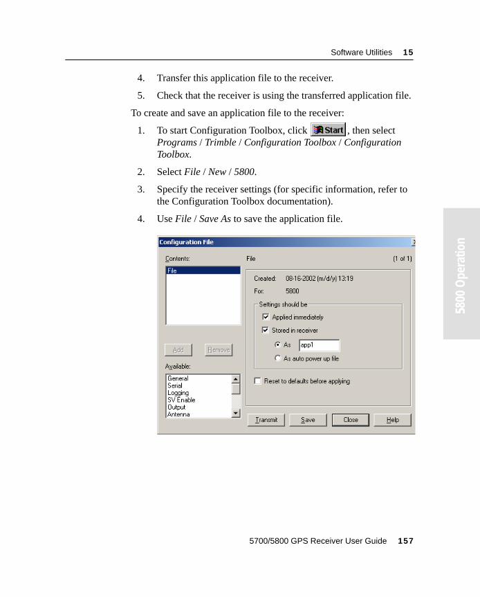
Software Utilities 15
55800
Ope
ratio
n
4. Transfer this application file to the receiver.
5. Check that the receiver is using the transferred application file.
To create and save an application file to the receiver:
1. To start Configuration Toolbox, click , then select Programs / Trimble / Configuration Toolbox / Configuration Toolbox.
2. Select File / New / 5800.
3. Specify the receiver settings (for specific information, refer to the Configuration Toolbox documentation).
4. Use File / Save As to save the application file.
5700/5800 GPS Receiver User Guide 157
15 Software Utilities
55800
Ope
ratio
n
To transfer the application file to the receiver:
1. Connect the power/serial data cable to the 5800 receiver, and connect to serial port on your computer.
2. Select File / Open to open the desired application file.
3. With the file open and the Configuration File dialog open, select Communications / Transmit File.
A message appears informing you that the application file has been successfully transferred. If an error occurs, select Communications / Transmit File again. This overrides any incompatibility in baud rates and enables successful communication.
4. To check whether the transfer was successful, close the Configuration File dialog and select Communications / Get File.
A list of all application files in the 5800 receiver appears. If you selected Applied immediately in the application file, the Current application file will contain the settings in the new file.
5. To apply a different file, select the file you require from the list and then select Communications / Activate File.
158 5700/5800 GPS Receiver User Guide
Software Utilities 15
55800
Ope
ratio
n
15.4WinFlash SoftwareWinFlash communicates with Trimble products to perform various functions including:
• installing software, firmware, and option upgrades
• running diagnostics (for example, retrieving configuration information)
• configuring radios
For more information, online help is also available when using WinFlash.
Note – WinFlash is a 32-bit application, so the local computer’s operating system must be Microsoft Windows 95, 98, NT, 2000, or Me. WinFlash does not run under earlier versions of Windows.
15.4.1 Installing WinFlash
WinFlash can be installed from the 5700/5800 GPS Receiver CD, or from the Trimble website.
Installing WinFlash from the 5700/5800 GPS receiver CD
A copy of WinFlash is included on the 5700/5800 receiver CD.
To install WinFlash from a CD:
1. Insert the disk into the CD drive on your computer.
2. From the main menu select Install individual software packages.
3. Select Install WinFlash vX.XX with 5700/5800 drivers and firmware.
4. Follow the onscreen instructions.
5700/5800 GPS Receiver User Guide 159
15 Software Utilities
55800
Ope
ratio
n
15.4.2 Upgrading firmware
Your 5800 receiver is supplied with the latest version of receiver firmware installed. If a later version becomes available, upgrade the firmware installed on your receiver.
WinFlash guides you through the firmware upgrade process. The steps required are described below. For more information, refer to the WinFlash Help.
To upgrade the 5800 receiver firmware:
1. Start WinFlash.
The Device Configuration screen appears.
2. From the Device type list select 5800 Receiver.
3. From the PC serial port field select the serial (COM) port on the computer that the receiver is connected to.
4. Click Next.
The Operation Selection screen appears. The Operations list shows all of the supported operations for the selected device. A description of the selected operation is shown in the Description field.
5. Select GPS software upgrade and click Next.
The GPS Software Selection window appears. This screen prompts you to select the software that you want to install on the 5800 receiver.
6. Select the latest version from the Available Software list and click Next.
The Settings Review window appears. This screen prompts you to connect the receiver, suggests a connection method, and then lists the receiver configuration and selected operation.
160 5700/5800 GPS Receiver User Guide
Software Utilities 15
55800
Ope
ratio
n
7. If all is correct, click Finish.
Based on the selections shown above, the Software Upgrade window appears and shows the status of the operation (for example, Establishing communication with the 5800. Please wait…).
8. Click OK.
The Software Upgrade window appears again and states that the operation was completed successfully.
9. Click Menu to select another operation, or click Exit to quit WinFlash.
10. If you click Exit, another screen appears asking you to confirm that you want to quit WinFlash. Click OK.
15.4.3 Adding frequencies for the 450 MHz internal radio
If your 5800 receiver has the optional internal 450 MHz radio installed, you must use WinFlash to add frequencies to the default list.
To add radio frequencies:
1. Start WinFlash.
The Device Configuration screen appears.
2. From the Device type list select 5800 Receiver.
3. From the PC serial port field select the serial (COM) port on the computer that the receiver is connected to.
4. Click Next.
The Operation Selection screen appears. The Operations list shows all of the supported operations for the selected device. A description of the selected operation is shown in the Description field.
5700/5800 GPS Receiver User Guide 161
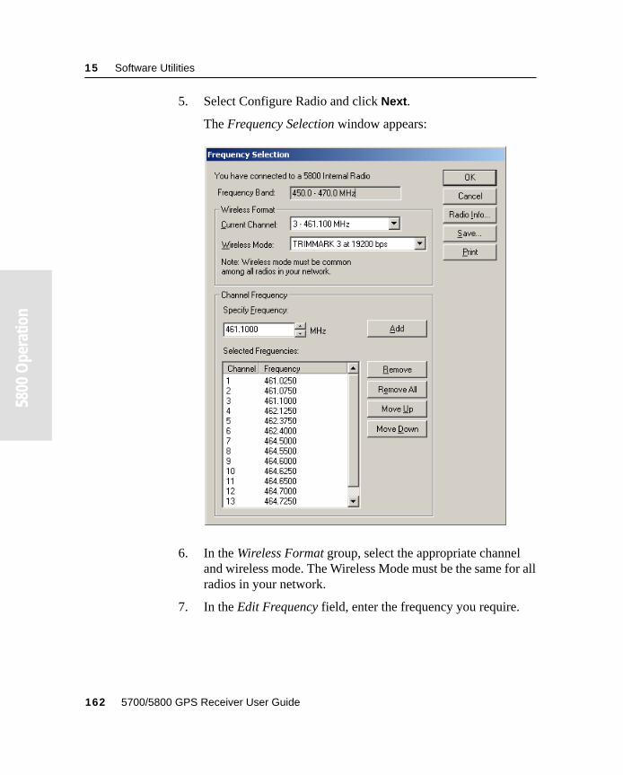
15 Software Utilities
55800
Ope
ratio
n
5. Select Configure Radio and click Next.
The Frequency Selection window appears:
6. In the Wireless Format group, select the appropriate channel and wireless mode. The Wireless Mode must be the same for all radios in your network.
7. In the Edit Frequency field, enter the frequency you require.
162 5700/5800 GPS Receiver User Guide
Software Utilities 15
55800
Ope
ratio
n
8. Press Add. The new frequency appears in the Selected Frequencies list.
Note – The frequencies that you program must conform to the channel spacing and minimum tuning requirements for the radio. To view this information, click Radio Info. You may select either 12.5 or 25 kHz channel spacing. All radios in your network must use the same channel spacing.
9. When you have configured all the frequencies you require, click OK.
WinFlash updates the 5800 receiver’s radio frequencies and then restarts the receiver.
15.4.4 Configuring the internal 900 MHz radio setup
To configure the internal 900 MHz radio, use one of the following:
• Trimble Survey Controller running on a Trimble controller
• WinFlash (provided on the Trimble 5700/5800 GPS Receiver CD)
The internal radio has 40 selectable networks. You must choose the same network that is configured in the base radio you want to receive from.
Trimble Survey Controller
To configure your radio network using Trimble Survey Controller:
1. Connect to the 5800 receiver with Bluetooth (or the appropriate data cable if necessary).
2. From the main menu on the controller, select Configuration.
3. In the dialog that appears, select Survey styles, then from the Type field, select RTK.
4. Select Rover radio, then from the Type field select Trimble Internal.
5700/5800 GPS Receiver User Guide 163
15 Software Utilities
55800
Ope
ratio
n
5. Tap the Connect softkey.
6. Once connected, in the Network number field enter the number of the network set on your base radio.
Note – The Base Radio Mode field is not used here.
7. Tap the Enter softkey to complete configuration.
WinFlash
To configure the radio network using WinFlash:
1. Connect the data/power cable to Port 1 on the receiver.
2. Connect the female DE-9 connector on the other end of the data/power cable to a serial (COM) port on the computer.
3. Start WinFlash. The Device Configuration dialog appears.
4. From the Device type list, select 5800 Receiver.
5. From the PC serial port field, select the serial port on the computer that the receiver is connected to and click Next.
6. From the Operation selection dialog, select Configure radio and click Next.
7. Confirm that your current settings are correct and click Finish. The Configure 900MHz radio dialog appears.
8. In the Network number field, select the same network that is set on your base radio.
9. In the Country setting field, select one of the following (according to how your base radio was shipped):
– Your country (if available). This sets the radio to the a specific frequency range being transmitted by the base radio.
– A single frequency. This limits the frequencies used to those authorized in your particular country.
10. Click OK.
WinFlash updates the radio settings and then restarts the receiver.
164 5700/5800 GPS Receiver User Guide

C H A P T E R
16
16 SpecificationsIn this chapter:
■ Introduction
■ Physical specifications
■ Positioning specifications
■ Technical specifications
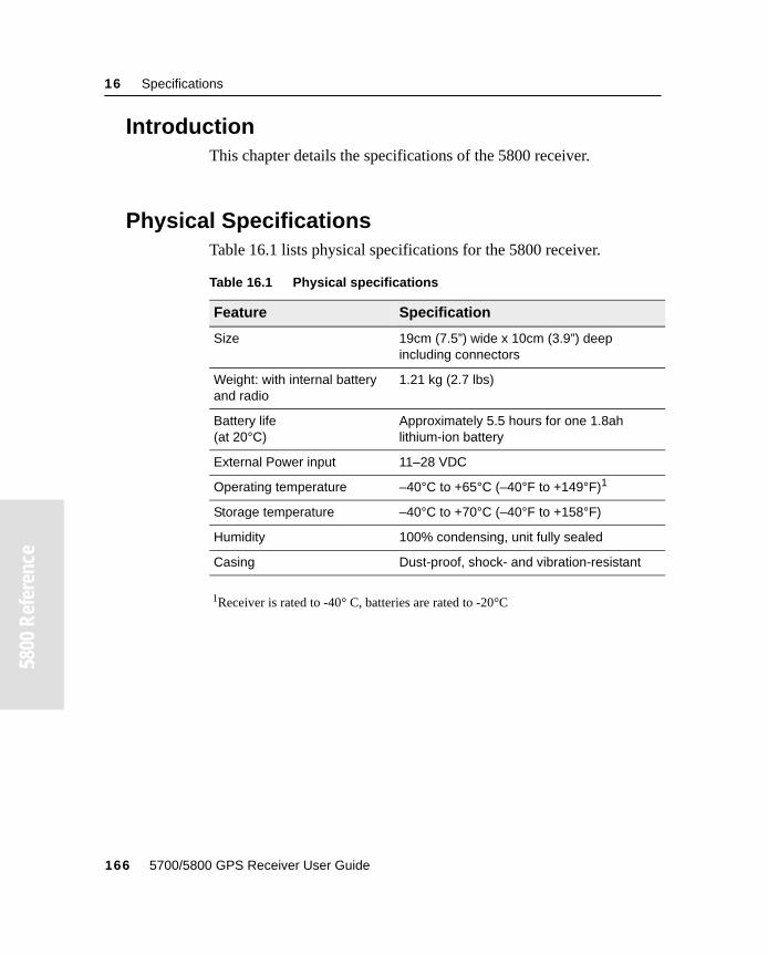
16 Specifications
55800
Ref
eren
ce
16.1IntroductionThis chapter details the specifications of the 5800 receiver.
16.2Physical SpecificationsTable 16.1 lists physical specifications for the 5800 receiver.
1Receiver is rated to -40° C, batteries are rated to -20°C
Table 16.1 Physical specifications
Feature Specification
Size 19cm (7.5”) wide x 10cm (3.9”) deep including connectors
Weight: with internal battery and radio
1.21 kg (2.7 lbs)
Battery life(at 20°C)
Approximately 5.5 hours for one 1.8ah lithium-ion battery
External Power input 11–28 VDC
Operating temperature –40°C to +65°C (–40°F to +149°F)1
Storage temperature –40°C to +70°C (–40°F to +158°F)
Humidity 100% condensing, unit fully sealed
Casing Dust-proof, shock- and vibration-resistant
166 5700/5800 GPS Receiver User Guide
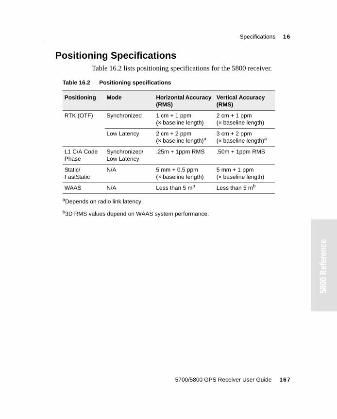
Specifications 16
55800
Ref
eren
ce
16.3Positioning SpecificationsTable 16.2 lists positioning specifications for the 5800 receiver.
Table 16.2 Positioning specifications
Positioning Mode Horizontal Accuracy (RMS)
Vertical Accuracy (RMS)
RTK (OTF) Synchronized 1 cm + 1 ppm(× baseline length)
2 cm + 1 ppm(× baseline length)
Low Latency 2 cm + 2 ppm (× baseline length)a
aDepends on radio link latency.
3 cm + 2 ppm (× baseline length)a
L1 C/A Code Phase
Synchronized/Low Latency
.25m + 1ppm RMS .50m + 1ppm RMS
Static/FastStatic
N/A 5 mm + 0.5 ppm(× baseline length)
5 mm + 1 ppm(× baseline length)
WAAS N/A Less than 5 mb
b3D RMS values depend on WAAS system performance.
Less than 5 mb
5700/5800 GPS Receiver User Guide 167
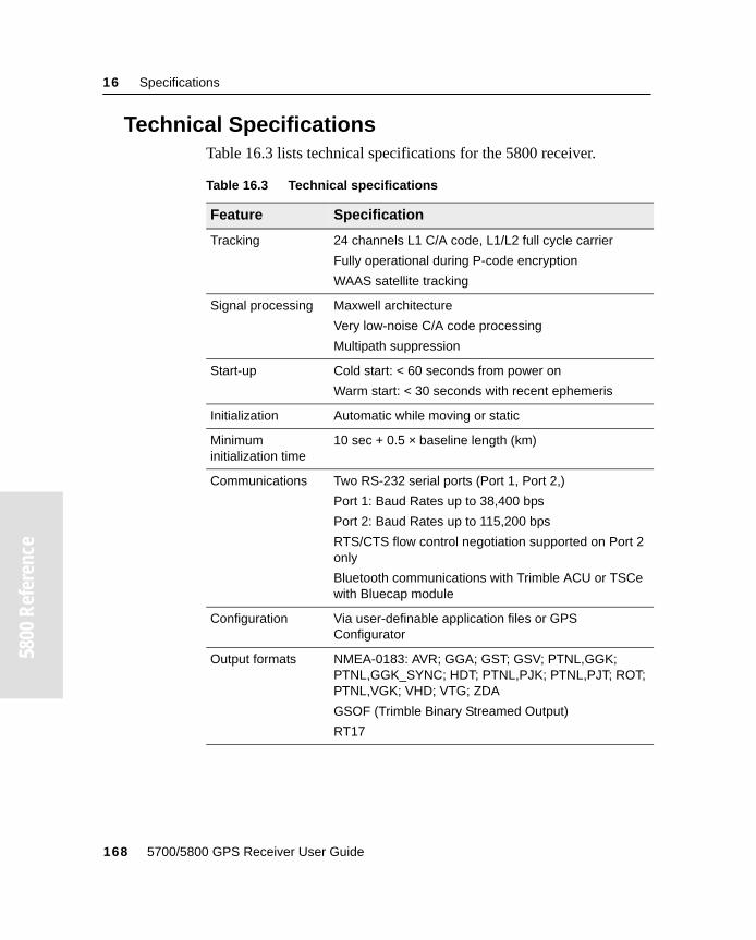
16 Specifications
55800
Ref
eren
ce
16.4Technical SpecificationsTable 16.3 lists technical specifications for the 5800 receiver.
Table 16.3 Technical specifications
Feature Specification
Tracking 24 channels L1 C/A code, L1/L2 full cycle carrier
Fully operational during P-code encryption
WAAS satellite tracking
Signal processing Maxwell architecture
Very low-noise C/A code processing
Multipath suppression
Start-up Cold start: < 60 seconds from power on
Warm start: < 30 seconds with recent ephemeris
Initialization Automatic while moving or static
Minimum initialization time
10 sec + 0.5 × baseline length (km)
Communications Two RS-232 serial ports (Port 1, Port 2,)
Port 1: Baud Rates up to 38,400 bps
Port 2: Baud Rates up to 115,200 bps
RTS/CTS flow control negotiation supported on Port 2 only
Bluetooth communications with Trimble ACU or TSCe with Bluecap module
Configuration Via user-definable application files or GPS Configurator
Output formats NMEA-0183: AVR; GGA; GST; GSV; PTNL,GGK; PTNL,GGK_SYNC; HDT; PTNL,PJK; PTNL,PJT; ROT; PTNL,VGK; VHD; VTG; ZDA
GSOF (Trimble Binary Streamed Output)
RT17
168 5700/5800 GPS Receiver User Guide
C H A P T E R
17
17 Default SettingsIn this chapter:
■ Introduction
■ Default settings
■ Resetting to factory defaults
17 Default Settings
55800
Ref
eren
ce
17.1IntroductionAll 5800 receiver settings are stored in application files. The Default application file, Default.cfg, is stored permanently in the receiver, and contains the factory default settings for the 5800 receiver. Whenever the receiver is reset to its factory defaults, the current settings (stored in the Current application file, Current.cfg) are reset to the values in the Default application file.
You cannot modify the Default application file. However, if there is a Power Up application file (Power_Up.cfg) in the receiver, the settings in this file can be applied immediately after the Default application file, overriding the factory defaults.
For more information about application files, see Application Files, page 147.
170 5700/5800 GPS Receiver User Guide
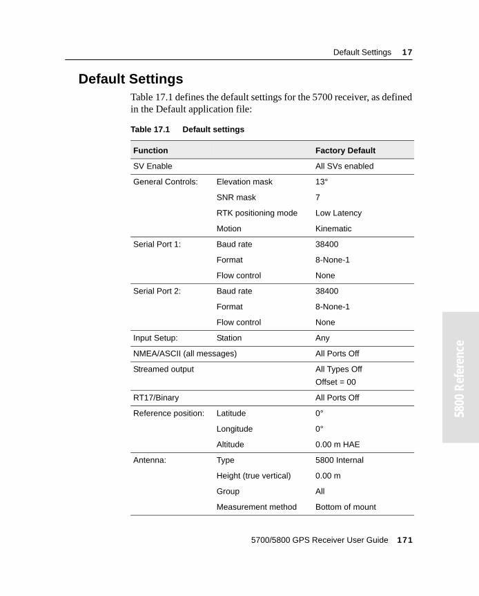
Default Settings 17
55800
Ref
eren
ce
17.2Default SettingsTable 17.1 defines the default settings for the 5700 receiver, as defined in the Default application file:
Table 17.1 Default settings
Function Factory Default
SV Enable All SVs enabled
General Controls: Elevation mask 13°
SNR mask 7
RTK positioning mode Low Latency
Motion Kinematic
Serial Port 1: Baud rate 38400
Format 8-None-1
Flow control None
Serial Port 2: Baud rate 38400
Format 8-None-1
Flow control None
Input Setup: Station Any
NMEA/ASCII (all messages) All Ports Off
Streamed output All Types Off
Offset = 00
RT17/Binary All Ports Off
Reference position: Latitude 0°
Longitude 0°
Altitude 0.00 m HAE
Antenna: Type 5800 Internal
Height (true vertical) 0.00 m
Group All
Measurement method Bottom of mount
5700/5800 GPS Receiver User Guide 171
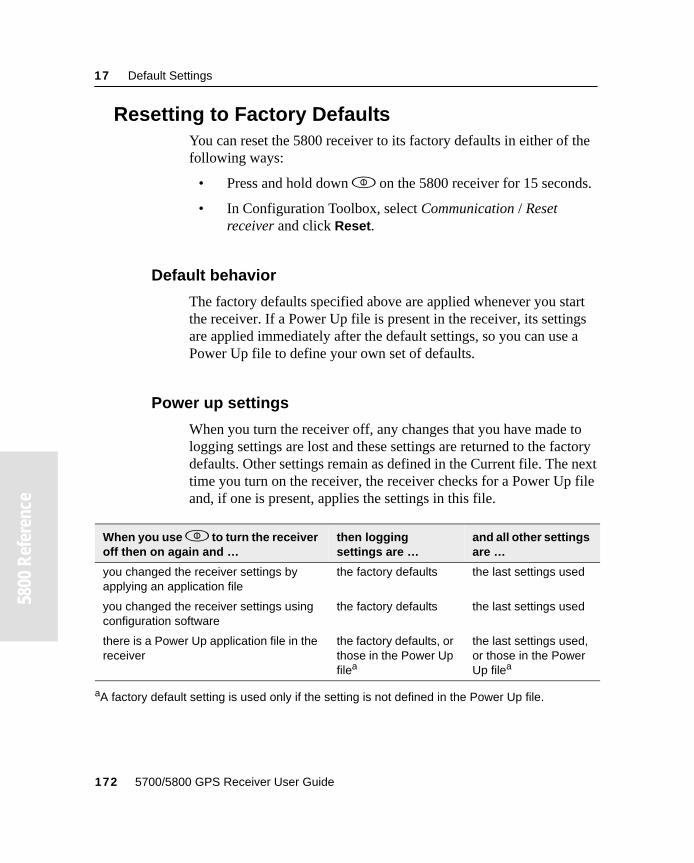
17 Default Settings
55800
Ref
eren
ce
17.3Resetting to Factory DefaultsYou can reset the 5800 receiver to its factory defaults in either of the following ways:
• Press and hold down p on the 5800 receiver for 15 seconds.
• In Configuration Toolbox, select Communication / Reset receiver and click Reset.
17.3.1 Default behavior
The factory defaults specified above are applied whenever you start the receiver. If a Power Up file is present in the receiver, its settings are applied immediately after the default settings, so you can use a Power Up file to define your own set of defaults.
17.3.2 Power up settings
When you turn the receiver off, any changes that you have made to logging settings are lost and these settings are returned to the factory defaults. Other settings remain as defined in the Current file. The next time you turn on the receiver, the receiver checks for a Power Up file and, if one is present, applies the settings in this file.
When you use p to turn the receiver off then on again and …
then logging settings are …
and all other settings are …
you changed the receiver settings by applying an application file
the factory defaults the last settings used
you changed the receiver settings using configuration software
the factory defaults the last settings used
there is a Power Up application file in the receiver
the factory defaults, or those in the Power Up filea
aA factory default setting is used only if the setting is not defined in the Power Up file.
the last settings used, or those in the Power Up filea
172 5700/5800 GPS Receiver User Guide

C H A P T E R
18
18 Cables and ConnectorsIn this chapter:
■ Introduction
■ Port 1 and 2 connectors
■ Power/serial data cable
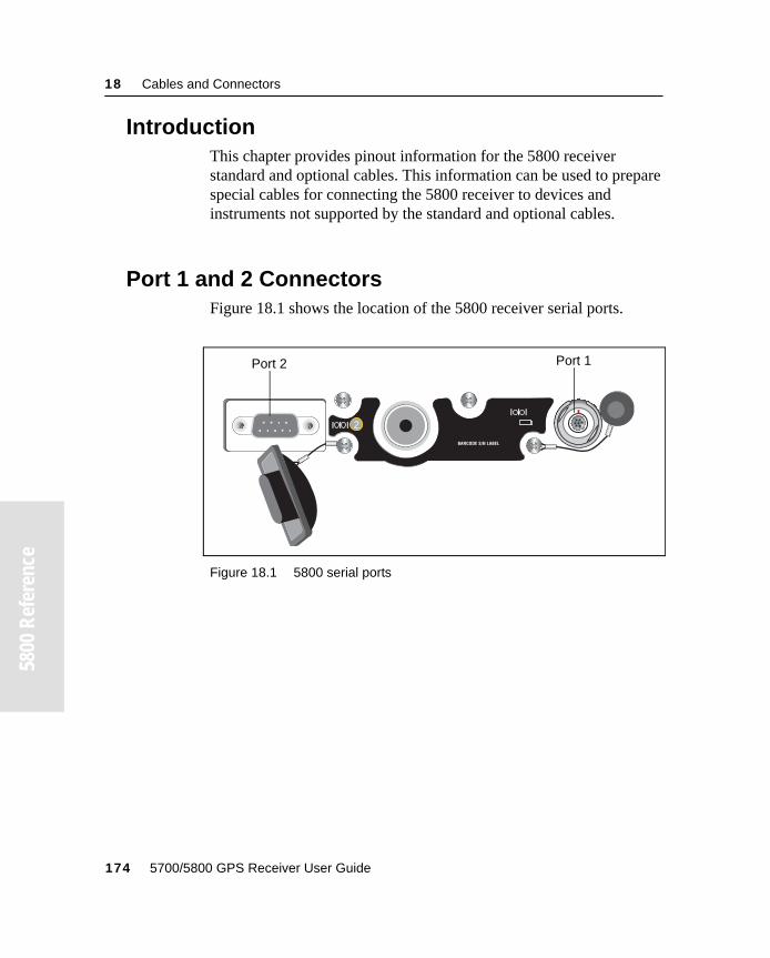
18 Cables and Connectors
5800
Ref
eren
ce558
00 R
efer
ence
18.1IntroductionThis chapter provides pinout information for the 5800 receiver standard and optional cables. This information can be used to prepare special cables for connecting the 5800 receiver to devices and instruments not supported by the standard and optional cables.
18.2Port 1 and 2 ConnectorsFigure 18.1 shows the location of the 5800 receiver serial ports.
Figure 18.1 5800 serial ports
12
BARCODE S/N LABEL
Port 1Port 2
174 5700/5800 GPS Receiver User Guide
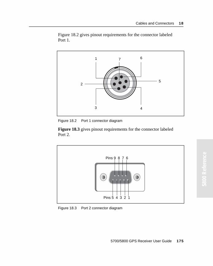
Cables and Connectors 18
55800
Ref
eren
ce
Figure 18.2 gives pinout requirements for the connector labeledPort 1.
Figure 18.2 Port 1 connector diagram
Figure 18.3 gives pinout requirements for the connector labeledPort 2.
Figure 18.3 Port 2 connector diagram
71
3
6
4
25
Pins 9 8 7 6
Pins 5 4 3 2 1
5700/5800 GPS Receiver User Guide 175
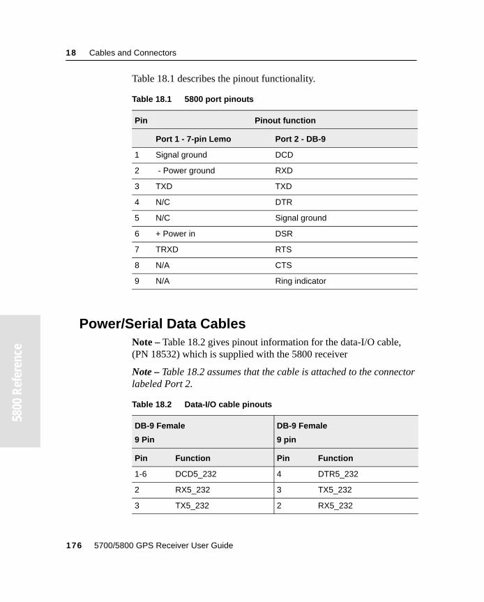
18 Cables and Connectors
5800
Ref
eren
ce558
00 R
efer
ence
Table 18.1 describes the pinout functionality.
18.3Power/Serial Data CablesNote – Table 18.2 gives pinout information for the data-I/O cable, (PN 18532) which is supplied with the 5800 receiver
Note – Table 18.2 assumes that the cable is attached to the connector labeled Port 2.
Table 18.1 5800 port pinouts
Pin Pinout function
Port 1 - 7-pin Lemo Port 2 - DB-9
1 Signal ground DCD
2 - Power ground RXD
3 TXD TXD
4 N/C DTR
5 N/C Signal ground
6 + Power in DSR
7 TRXD RTS
8 N/A CTS
9 N/A Ring indicator
Table 18.2 Data-I/O cable pinouts
DB-9 Female
9 Pin
DB-9 Female
9 pin
Pin Function Pin Function
1-6 DCD5_232 4 DTR5_232
2 RX5_232 3 TX5_232
3 TX5_232 2 RX5_232
176 5700/5800 GPS Receiver User Guide
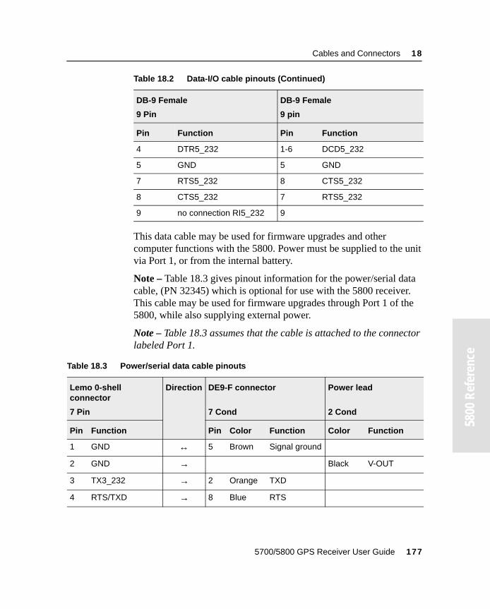
Cables and Connectors 18
55800
Ref
eren
ce
This data cable may be used for firmware upgrades and other computer functions with the 5800. Power must be supplied to the unit via Port 1, or from the internal battery.
Note – Table 18.3 gives pinout information for the power/serial data cable, (PN 32345) which is optional for use with the 5800 receiver. This cable may be used for firmware upgrades through Port 1 of the 5800, while also supplying external power.
Note – Table 18.3 assumes that the cable is attached to the connector labeled Port 1.
4 DTR5_232 1-6 DCD5_232
5 GND 5 GND
7 RTS5_232 8 CTS5_232
8 CTS5_232 7 RTS5_232
9 no connection RI5_232 9
Table 18.3 Power/serial data cable pinouts
Lemo 0-shell connector
7 Pin
Direction DE9-F connector
7 Cond
Power lead
2 Cond
Pin Function Pin Color Function Color Function
1 GND ↔ 5 Brown Signal ground
2 GND → Black V-OUT
3 TX3_232 → 2 Orange TXD
4 RTS/TXD → 8 Blue RTS
Table 18.2 Data-I/O cable pinouts (Continued)
DB-9 Female
9 Pin
DB-9 Female
9 pin
Pin Function Pin Function
5700/5800 GPS Receiver User Guide 177
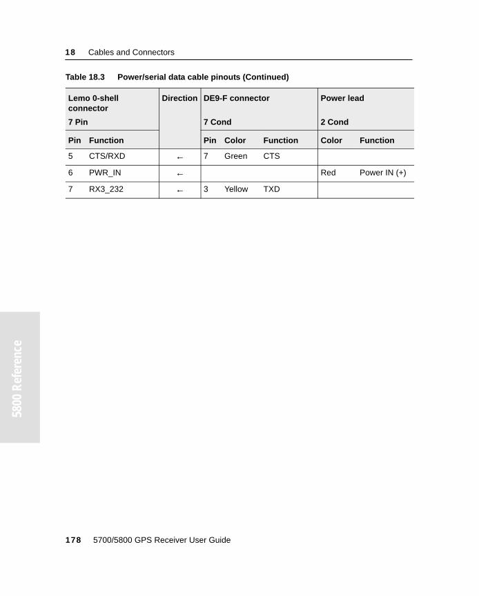
18 Cables and Connectors
5800
Ref
eren
ce558
00 R
efer
ence
5 CTS/RXD ← 7 Green CTS
6 PWR_IN ← Red Power IN (+)
7 RX3_232 ← 3 Yellow TXD
Table 18.3 Power/serial data cable pinouts (Continued)
Lemo 0-shell connector
7 Pin
Direction DE9-F connector
7 Cond
Power lead
2 Cond
Pin Function Pin Color Function Color Function
178 5700/5800 GPS Receiver User Guide

S E C T I O N
III
III5700 and 5800 APPENDIXES

A P P E N D I X
A
NMEA-0183 Output AIn this appendix:
■ Introduction
■ NMEA-0183 outputs
■ Common message elements
■ NMEA messages
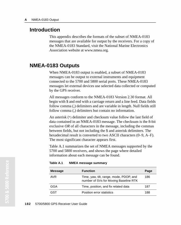
A NMEA-0183 Output
57
00 &
580
0 Re
fere
nce
A.1 IntroductionThis appendix describes the formats of the subset of NMEA-0183 messages that are available for output by the receivers. For a copy of the NMEA-0183 Standard, visit the National Marine Electronics Association website at www.nmea.org.
A.2 NMEA-0183 OutputsWhen NMEA-0183 output is enabled, a subset of NMEA-0183 messages can be output to external instruments and equipment connected to the 5700 and 5800 serial ports. These NMEA-0183 messages let external devices use selected data collected or computed by the GPS receiver.
All messages conform to the NMEA-0183 Version 2.30 format. All begin with $ and end with a carriage return and a line feed. Data fields follow comma (,) delimiters and are variable in length. Null fields still follow comma (,) delimiters but contain no information.
An asterisk (*) delimiter and checksum value follow the last field of data contained in an NMEA-0183 message. The checksum is the 8-bit exclusive OR of all characters in the message, including the commas between fields, but not including the $ and asterisk delimiters. The hexadecimal result is converted to two ASCII characters (0–9, A–F). The most significant character appears first.
Table A.1 summarizes the set of NMEA messages supported by the 5700 and 5800 receivers, and shows the page where detailed information about each message can be found.
Table A.1 NMEA message summary
Message Function Page
AVR Time, yaw, tilt, range, mode, PDOP, and number of SVs for Moving Baseline RTK
186
GGA Time, position, and fix related data 187
GST Position error statistics 188
182 5700/5800 GPS Receiver User Guide
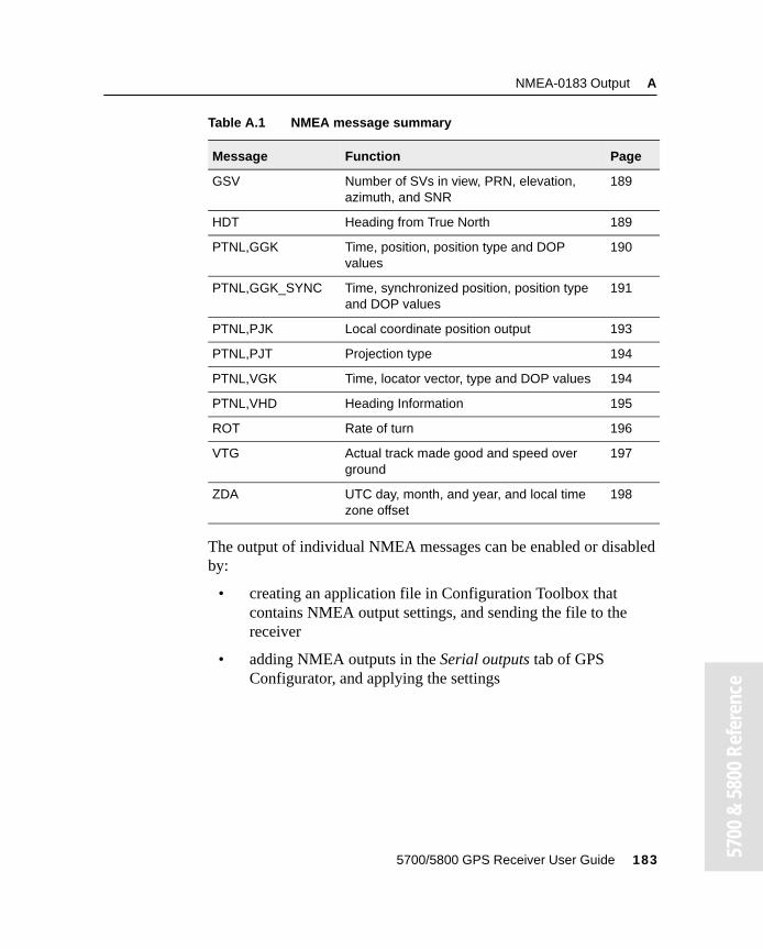
NMEA-0183 Output A
00 &
580
0 Re
fere
nce
The output of individual NMEA messages can be enabled or disabled by:
• creating an application file in Configuration Toolbox that contains NMEA output settings, and sending the file to the receiver
• adding NMEA outputs in the Serial outputs tab of GPS Configurator, and applying the settings
GSV Number of SVs in view, PRN, elevation, azimuth, and SNR
189
HDT Heading from True North 189
PTNL,GGK Time, position, position type and DOP values
190
PTNL,GGK_SYNC Time, synchronized position, position type and DOP values
191
PTNL,PJK Local coordinate position output 193
PTNL,PJT Projection type 194
PTNL,VGK Time, locator vector, type and DOP values 194
PTNL,VHD Heading Information 195
ROT Rate of turn 196
VTG Actual track made good and speed over ground
197
ZDA UTC day, month, and year, and local time zone offset
198
Table A.1 NMEA message summary
Message Function Page
5700/5800 GPS Receiver User Guide 183 57
A NMEA-0183 Output
57
00 &
580
0 Re
fere
nce
A.3 Common Message ElementsEach message contains:
• A message ID consisting of $GP followed by the message type. For example, the message ID of the GGA message is $GPGGA.
• A comma
• A number of fields that depend on message type, separated by commas
• An asterisk
• A checksum
Below is an example of a simple message with a message ID ($GPGGA), followed by 13 fields and checksum value:
$GPGGA,172814.0,3723.46587704,N,12202.26957864,W,2,6,1.2,18.893,M,-25.669,M,2.0,0031*4F
A.3.1 Message values
The following values can be found in NMEA messages that the receiver generates.
Latitude and Longitude
Latitude is represented as ddmm.mmmm and longitude is represented as dddmm.mmmm, where:
• dd or ddd is degrees
• mm.mmmm is minutes and decimal fractions of minutes
Direction
Direction (north, south, east, or west) is represented by a single character: N, S, E, or W.
184 5700/5800 GPS Receiver User Guide
NMEA-0183 Output A
00 &
580
0 Re
fere
nce
Time
Time values are presented in Universal Time Coordinated (UTC) and are represented as hhmmss.cc, where:
• hh is hours, from 00 to 23
• mm is minutes
• ss is seconds
• cc is hundredths of seconds
A.4 NMEA MessagesWhen NMEA-0183 output is enabled, the following messages can be generated.
5700/5800 GPS Receiver User Guide 185 57
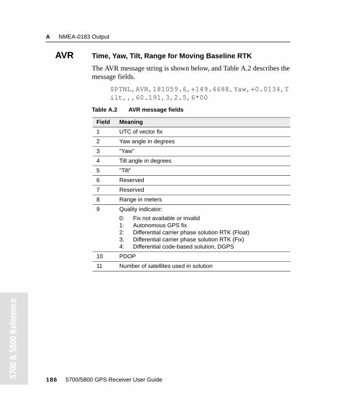
A NMEA-0183 Output
57
00 &
580
0 Re
fere
nce
AVR Time, Yaw, Tilt, Range for Moving Baseline RTK
The AVR message string is shown below, and Table A.2 describes the message fields.
$PTNL,AVR,181059.6,+149.4688,Yaw,+0.0134,Tilt,,,60.191,3,2.5,6*00
Table A.2 AVR message fields
Field Meaning
1 UTC of vector fix
2 Yaw angle in degrees
3 "Yaw"
4 Tilt angle in degrees
5 "Tilt"
6 Reserved
7 Reserved
8 Range in meters
9 Quality indicator:
0: Fix not available or invalid1: Autonomous GPS fix2: Differential carrier phase solution RTK (Float)3: Differential carrier phase solution RTK (Fix)4: Differential code-based solution, DGPS
10 PDOP
11 Number of satellites used in solution
186 5700/5800 GPS Receiver User Guide
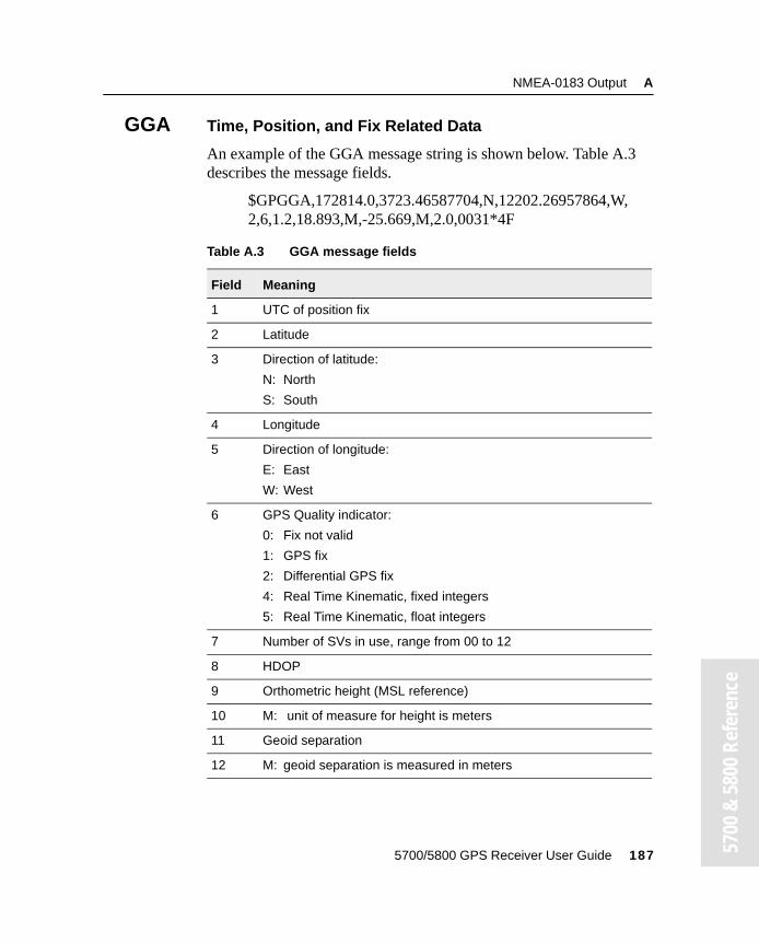
NMEA-0183 Output A
00 &
580
0 Re
fere
nce
GGA Time, Position, and Fix Related Data
An example of the GGA message string is shown below. Table A.3 describes the message fields.
$GPGGA,172814.0,3723.46587704,N,12202.26957864,W,2,6,1.2,18.893,M,-25.669,M,2.0,0031*4F
Table A.3 GGA message fields
Field Meaning
1 UTC of position fix
2 Latitude
3 Direction of latitude:
N: North
S: South
4 Longitude
5 Direction of longitude:
E: East
W: West
6 GPS Quality indicator:
0: Fix not valid
1: GPS fix
2: Differential GPS fix
4: Real Time Kinematic, fixed integers
5: Real Time Kinematic, float integers
7 Number of SVs in use, range from 00 to 12
8 HDOP
9 Orthometric height (MSL reference)
10 M: unit of measure for height is meters
11 Geoid separation
12 M: geoid separation is measured in meters
5700/5800 GPS Receiver User Guide 187 57
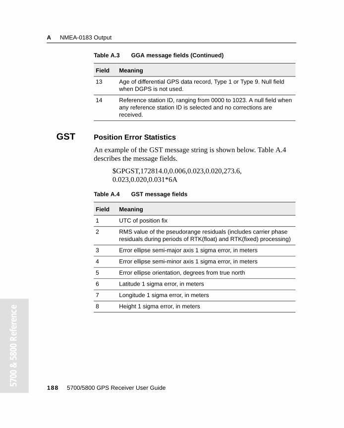
A NMEA-0183 Output
57
00 &
580
0 Re
fere
nce
GST Position Error Statistics
An example of the GST message string is shown below. Table A.4 describes the message fields.
$GPGST,172814.0,0.006,0.023,0.020,273.6,0.023,0.020,0.031*6A
13 Age of differential GPS data record, Type 1 or Type 9. Null field when DGPS is not used.
14 Reference station ID, ranging from 0000 to 1023. A null field when any reference station ID is selected and no corrections are received.
Table A.4 GST message fields
Field Meaning
1 UTC of position fix
2 RMS value of the pseudorange residuals (includes carrier phase residuals during periods of RTK(float) and RTK(fixed) processing)
3 Error ellipse semi-major axis 1 sigma error, in meters
4 Error ellipse semi-minor axis 1 sigma error, in meters
5 Error ellipse orientation, degrees from true north
6 Latitude 1 sigma error, in meters
7 Longitude 1 sigma error, in meters
8 Height 1 sigma error, in meters
Table A.3 GGA message fields (Continued)
Field Meaning
188 5700/5800 GPS Receiver User Guide
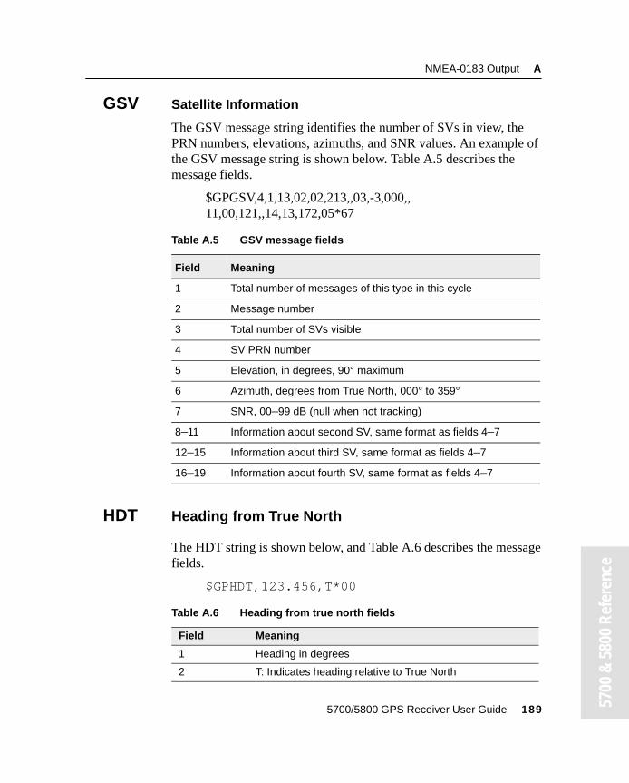
NMEA-0183 Output A
00 &
580
0 Re
fere
nce
GSV Satellite Information
The GSV message string identifies the number of SVs in view, the PRN numbers, elevations, azimuths, and SNR values. An example of the GSV message string is shown below. Table A.5 describes the message fields.
$GPGSV,4,1,13,02,02,213,,03,-3,000,,11,00,121,,14,13,172,05*67
HDT Heading from True North
The HDT string is shown below, and Table A.6 describes the message fields.
$GPHDT,123.456,T*00
Table A.5 GSV message fields
Field Meaning
1 Total number of messages of this type in this cycle
2 Message number
3 Total number of SVs visible
4 SV PRN number
5 Elevation, in degrees, 90° maximum
6 Azimuth, degrees from True North, 000° to 359°
7 SNR, 00–99 dB (null when not tracking)
8–11 Information about second SV, same format as fields 4–7
12–15 Information about third SV, same format as fields 4–7
16–19 Information about fourth SV, same format as fields 4–7
Table A.6 Heading from true north fields
Field Meaning
1 Heading in degrees
2 T: Indicates heading relative to True North
5700/5800 GPS Receiver User Guide 189 57
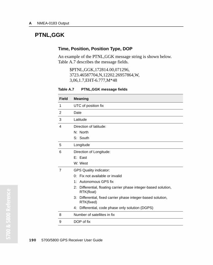
A NMEA-0183 Output
57
00 &
580
0 Re
fere
nce
PTNL,GGK
Time, Position, Position Type, DOP
An example of the PTNL,GGK message string is shown below. Table A.7 describes the message fields.
$PTNL,GGK,172814.00,071296,3723.46587704,N,12202.26957864,W,3,06,1.7,EHT-6.777,M*48
Table A.7 PTNL,GGK message fields
Field Meaning
1 UTC of position fix
2 Date
3 Latitude
4 Direction of latitude:
N: North
S: South
5 Longitude
6 Direction of Longitude:
E: East
W: West
7 GPS Quality indicator:
0: Fix not available or invalid
1: Autonomous GPS fix
2: Differential, floating carrier phase integer-based solution, RTK(float)
3: Differential, fixed carrier phase integer-based solution, RTK(fixed)
4: Differential, code phase only solution (DGPS)
8 Number of satellites in fix
9 DOP of fix
190 5700/5800 GPS Receiver User Guide
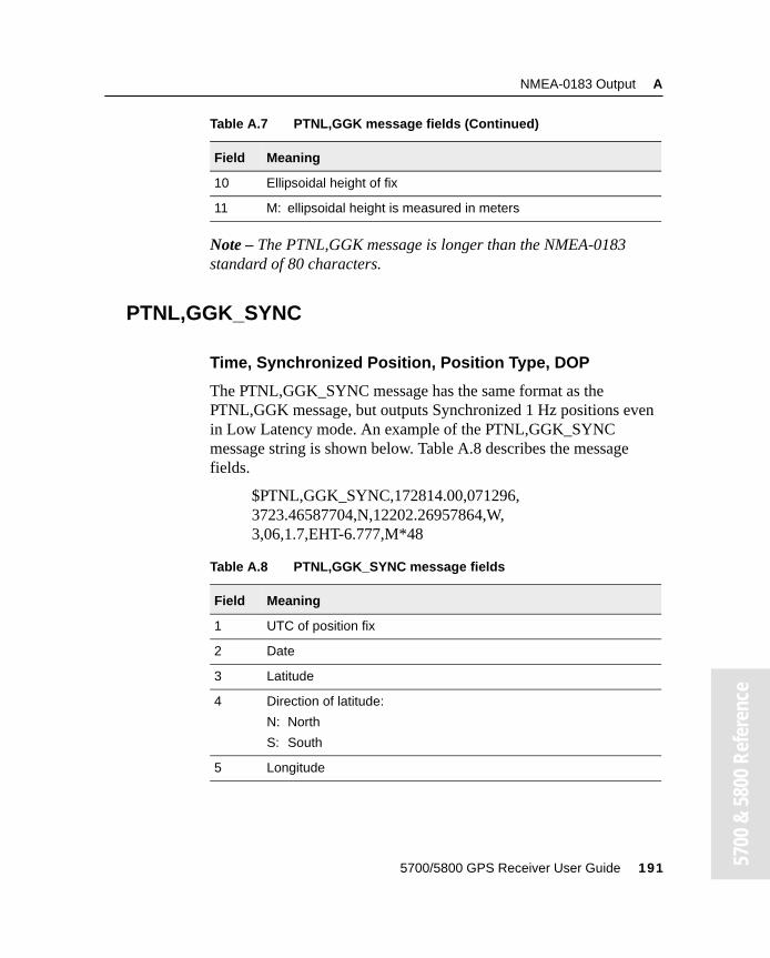
NMEA-0183 Output A
00 &
580
0 Re
fere
nce
Note – The PTNL,GGK message is longer than the NMEA-0183 standard of 80 characters.
PTNL,GGK_SYNC
Time, Synchronized Position, Position Type, DOP
The PTNL,GGK_SYNC message has the same format as the PTNL,GGK message, but outputs Synchronized 1 Hz positions even in Low Latency mode. An example of the PTNL,GGK_SYNC message string is shown below. Table A.8 describes the message fields.
$PTNL,GGK_SYNC,172814.00,071296,3723.46587704,N,12202.26957864,W,3,06,1.7,EHT-6.777,M*48
10 Ellipsoidal height of fix
11 M: ellipsoidal height is measured in meters
Table A.8 PTNL,GGK_SYNC message fields
Field Meaning
1 UTC of position fix
2 Date
3 Latitude
4 Direction of latitude:
N: North
S: South
5 Longitude
Table A.7 PTNL,GGK message fields (Continued)
Field Meaning
5700/5800 GPS Receiver User Guide 191 57
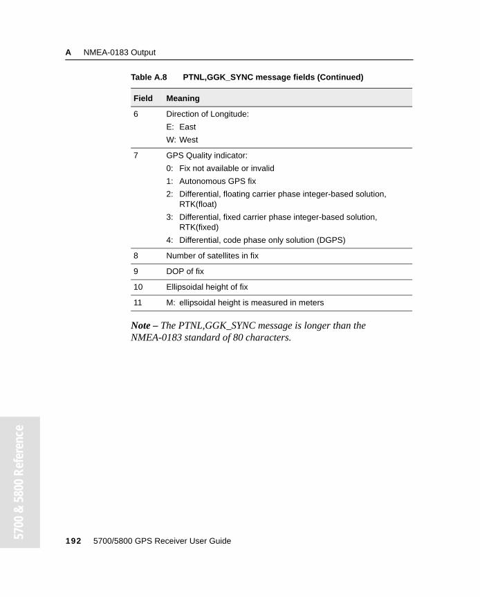
A NMEA-0183 Output
57
00 &
580
0 Re
fere
nce
Note – The PTNL,GGK_SYNC message is longer than the NMEA-0183 standard of 80 characters.
6 Direction of Longitude:
E: East
W: West
7 GPS Quality indicator:
0: Fix not available or invalid
1: Autonomous GPS fix
2: Differential, floating carrier phase integer-based solution, RTK(float)
3: Differential, fixed carrier phase integer-based solution, RTK(fixed)
4: Differential, code phase only solution (DGPS)
8 Number of satellites in fix
9 DOP of fix
10 Ellipsoidal height of fix
11 M: ellipsoidal height is measured in meters
Table A.8 PTNL,GGK_SYNC message fields (Continued)
Field Meaning
192 5700/5800 GPS Receiver User Guide
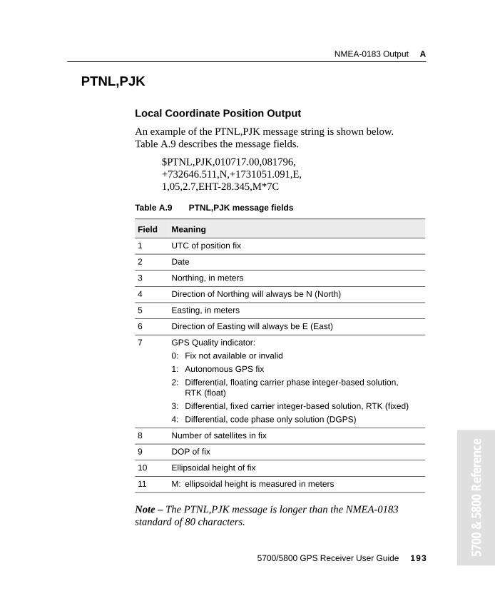
NMEA-0183 Output A
00 &
580
0 Re
fere
nce
PTNL,PJK
Local Coordinate Position Output
An example of the PTNL,PJK message string is shown below. Table A.9 describes the message fields.
$PTNL,PJK,010717.00,081796,+732646.511,N,+1731051.091,E,1,05,2.7,EHT-28.345,M*7C
Note – The PTNL,PJK message is longer than the NMEA-0183 standard of 80 characters.
Table A.9 PTNL,PJK message fields
Field Meaning
1 UTC of position fix
2 Date
3 Northing, in meters
4 Direction of Northing will always be N (North)
5 Easting, in meters
6 Direction of Easting will always be E (East)
7 GPS Quality indicator:
0: Fix not available or invalid
1: Autonomous GPS fix
2: Differential, floating carrier phase integer-based solution, RTK (float)
3: Differential, fixed carrier integer-based solution, RTK (fixed)
4: Differential, code phase only solution (DGPS)
8 Number of satellites in fix
9 DOP of fix
10 Ellipsoidal height of fix
11 M: ellipsoidal height is measured in meters
5700/5800 GPS Receiver User Guide 193 57
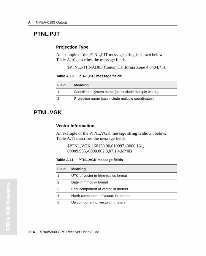
A NMEA-0183 Output
57
00 &
580
0 Re
fere
nce
PTNL,PJT
Projection Type
An example of the PTNL,PJT message string is shown below. Table A.10 describes the message fields.
$PTNL,PJT,NAD83(Conus),California Zone 4 0404,*51
PTNL,VGK
Vector Information
An example of the PTNL,VGK message string is shown below. Table A.11 describes the message fields.
$PTNL,VGK,160159.00,010997,-0000.161,00009.985,-0000.002,3,07,1,4,M*0B
Table A.10 PTNL,PJT message fields
Field Meaning
1 Coordinate system name (can include multiple words)
2 Projection name (can include multiple coordinates)
Table A.11 PTNL,VGK message fields
Field Meaning
1 UTC of vector in hhmmss.ss format
2 Date in mmddyy format
3 East component of vector, in meters
4 North component of vector, in meters
5 Up component of vector, in meters
194 5700/5800 GPS Receiver User Guide
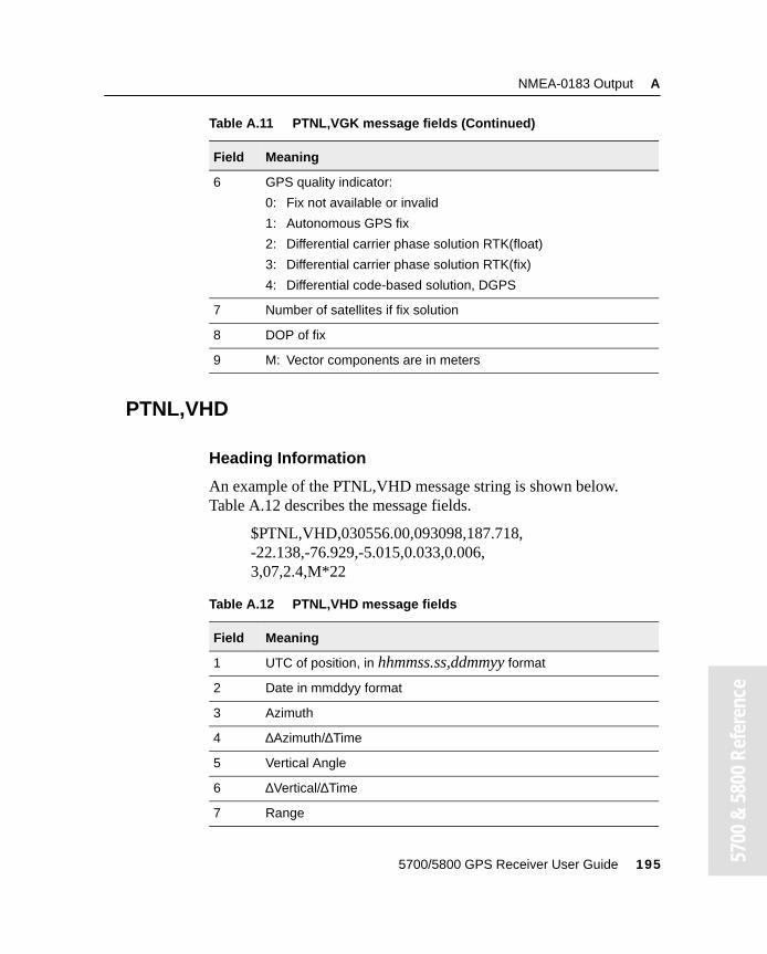
NMEA-0183 Output A
00 &
580
0 Re
fere
nce
PTNL,VHD
Heading Information
An example of the PTNL,VHD message string is shown below. Table A.12 describes the message fields.
$PTNL,VHD,030556.00,093098,187.718,-22.138,-76.929,-5.015,0.033,0.006,3,07,2.4,M*22
6 GPS quality indicator:
0: Fix not available or invalid
1: Autonomous GPS fix
2: Differential carrier phase solution RTK(float)
3: Differential carrier phase solution RTK(fix)
4: Differential code-based solution, DGPS
7 Number of satellites if fix solution
8 DOP of fix
9 M: Vector components are in meters
Table A.12 PTNL,VHD message fields
Field Meaning
1 UTC of position, in hhmmss.ss,ddmmyy format
2 Date in mmddyy format
3 Azimuth
4 ∆Azimuth/∆Time
5 Vertical Angle
6 ∆Vertical/∆Time
7 Range
Table A.11 PTNL,VGK message fields (Continued)
Field Meaning
5700/5800 GPS Receiver User Guide 195 57
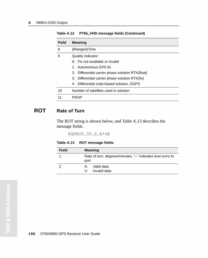
A NMEA-0183 Output
57
00 &
580
0 Re
fere
nce
ROT Rate of Turn
The ROT string is shown below, and Table A.13 describes the message fields.
$GPROT,35.6,A*4E
8 ∆Range/∆Time
9 Quality indicator:
0: Fix not available or invalid
1: Autonomous GPS fix
2: Differential carrier phase solution RTK(float)
3: Differential carrier phase solution RTK(fix)
4: Differential code-based solution, DGPS
10 Number of satellites used in solution
11 PDOP
Table A.13 ROT message fields
Field Meaning
1 Rate of turn, degrees/minutes, "–" indicates bow turns to port
2 A: Valid dataV: Invalid data
Table A.12 PTNL,VHD message fields (Continued)
Field Meaning
196 5700/5800 GPS Receiver User Guide
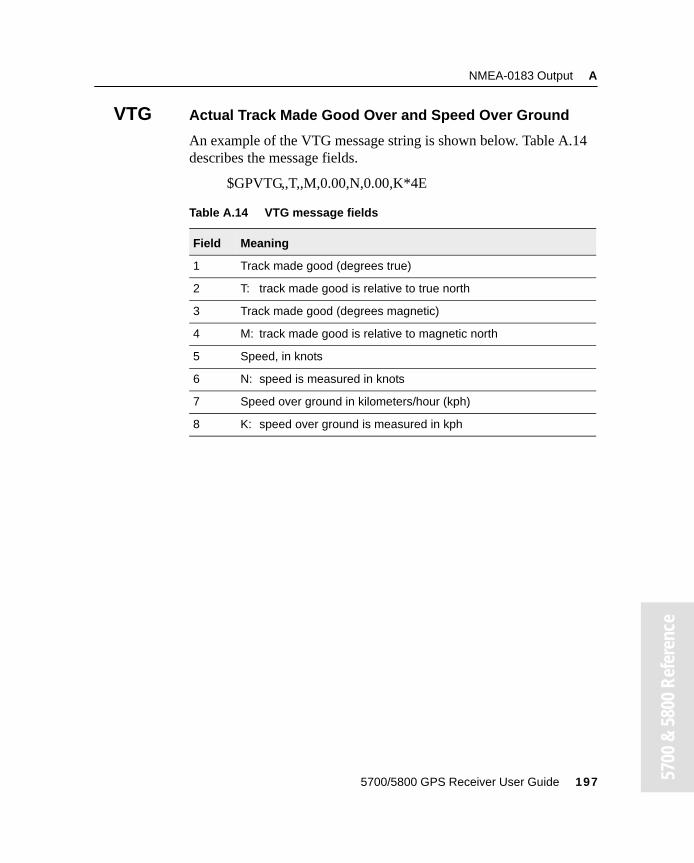
NMEA-0183 Output A
00 &
580
0 Re
fere
nce
VTG Actual Track Made Good Over and Speed Over Ground
An example of the VTG message string is shown below. Table A.14 describes the message fields.
$GPVTG,,T,,M,0.00,N,0.00,K*4E
Table A.14 VTG message fields
Field Meaning
1 Track made good (degrees true)
2 T: track made good is relative to true north
3 Track made good (degrees magnetic)
4 M: track made good is relative to magnetic north
5 Speed, in knots
6 N: speed is measured in knots
7 Speed over ground in kilometers/hour (kph)
8 K: speed over ground is measured in kph
5700/5800 GPS Receiver User Guide 197 57
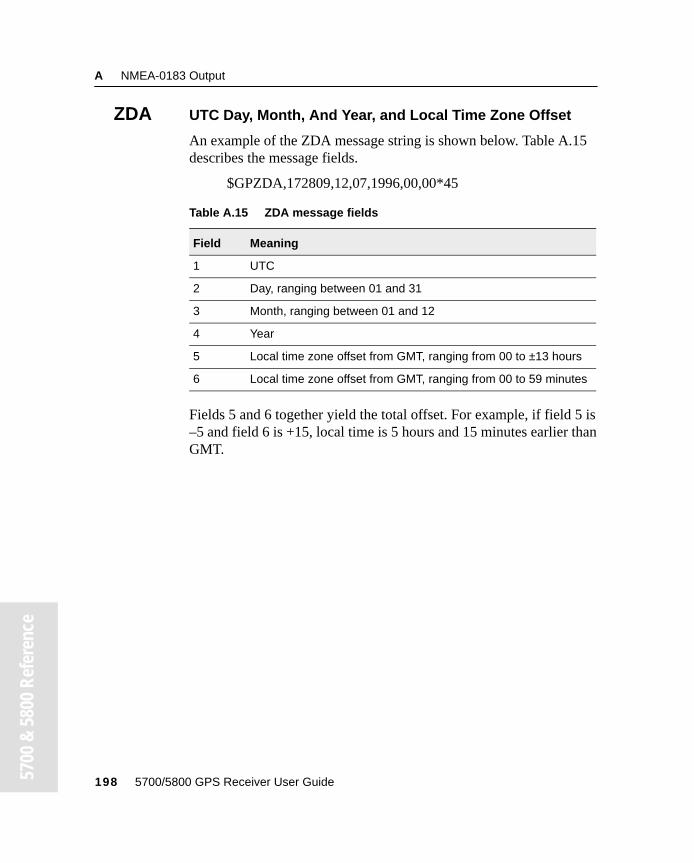
A NMEA-0183 Output
57
00 &
580
0 Re
fere
nce
ZDA UTC Day, Month, And Year, and Local Time Zone Offset
An example of the ZDA message string is shown below. Table A.15 describes the message fields.
$GPZDA,172809,12,07,1996,00,00*45
Fields 5 and 6 together yield the total offset. For example, if field 5 is –5 and field 6 is +15, local time is 5 hours and 15 minutes earlier than GMT.
Table A.15 ZDA message fields
Field Meaning
1 UTC
2 Day, ranging between 01 and 31
3 Month, ranging between 01 and 12
4 Year
5 Local time zone offset from GMT, ranging from 00 to ±13 hours
6 Local time zone offset from GMT, ranging from 00 to 59 minutes
198 5700/5800 GPS Receiver User Guide
A P P E N D I X
B
Troubleshooting BIn this appendix:
■ Table B.1 LED conditions
■ Table B.2 Receiver issues
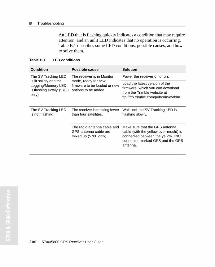
B Troubleshooting
57
00 &
580
0 Re
fere
nce
An LED that is flashing quickly indicates a condition that may require attention, and an unlit LED indicates that no operation is occurring. Table B.1 describes some LED conditions, possible causes, and how to solve them.
Table B.1 LED conditions
Condition Possible cause Solution
The SV Tracking LED is lit solidly and the Logging/Memory LED is flashing slowly. (5700 only)
The receiver is in Monitor mode, ready for new firmware to be loaded or new options to be added.
Power the receiver off or on.
Load the latest version of the firmware, which you can download from the Trimble website at ftp://ftp.trimble.com/pub/survey/bin/
The SV Tracking LED is not flashing.
The receiver is tracking fewer than four satellites.
Wait until the SV Tracking LED is flashing slowly.
The radio antenna cable and GPS antenna cable are mixed up.(5700 only)
Make sure that the GPS antenna cable (with the yellow over-mould) is connected between the yellow TNC connector marked GPS and the GPS antenna.
200 5700/5800 GPS Receiver User Guide
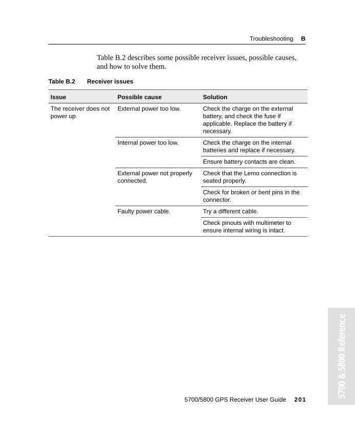
Troubleshooting B
00 &
580
0 Re
fere
nce
Table B.2 describes some possible receiver issues, possible causes, and how to solve them.
Table B.2 Receiver issues
Issue Possible cause Solution
The receiver does not power up.
External power too low. Check the charge on the external battery, and check the fuse if applicable. Replace the battery if necessary.
Internal power too low. Check the charge on the internal batteries and replace if necessary.
Ensure battery contacts are clean.
External power not properly connected.
Check that the Lemo connection is seated properly.
Check for broken or bent pins in the connector.
Faulty power cable. Try a different cable.
Check pinouts with multimeter to ensure internal wiring is intact.
5700/5800 GPS Receiver User Guide 201 57
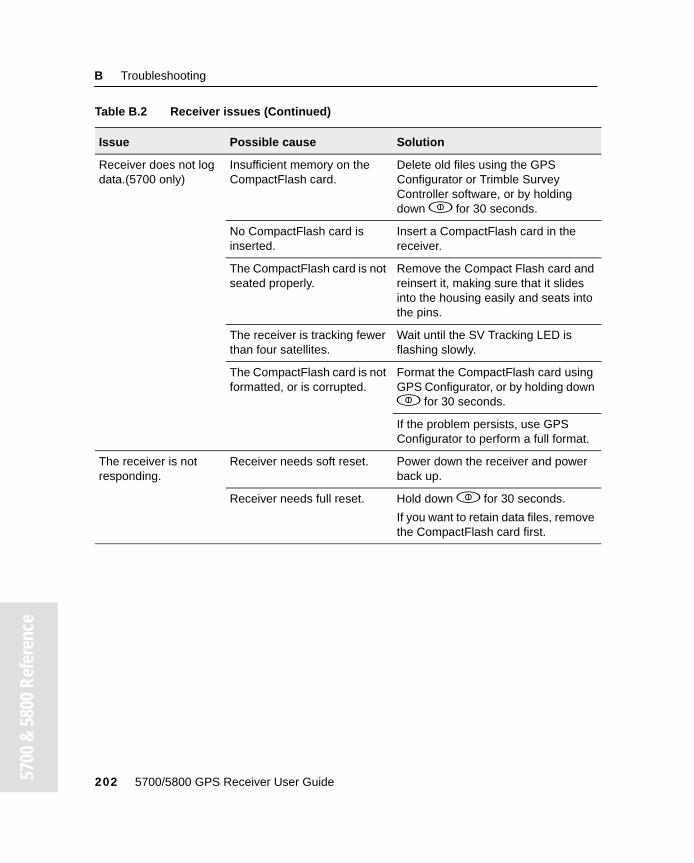
B Troubleshooting
57
00 &
580
0 Re
fere
nce
Receiver does not log data.(5700 only)
Insufficient memory on the CompactFlash card.
Delete old files using the GPS Configurator or Trimble Survey Controller software, or by holding down p for 30 seconds.
No CompactFlash card is inserted.
Insert a CompactFlash card in the receiver.
The CompactFlash card is not seated properly.
Remove the Compact Flash card and reinsert it, making sure that it slides into the housing easily and seats into the pins.
The receiver is tracking fewer than four satellites.
Wait until the SV Tracking LED is flashing slowly.
The CompactFlash card is not formatted, or is corrupted.
Format the CompactFlash card using GPS Configurator, or by holding down p for 30 seconds.
If the problem persists, use GPS Configurator to perform a full format.
The receiver is not responding.
Receiver needs soft reset. Power down the receiver and power back up.
Receiver needs full reset. Hold down p for 30 seconds.
If you want to retain data files, remove the CompactFlash card first.
Table B.2 Receiver issues (Continued)
Issue Possible cause Solution
202 5700/5800 GPS Receiver User Guide
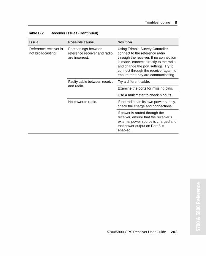
Troubleshooting B
00 &
580
0 Re
fere
nce
Reference receiver is not broadcasting.
Port settings between reference receiver and radio are incorrect.
Using Trimble Survey Controller, connect to the reference radio through the receiver. If no connection is made, connect directly to the radio and change the port settings. Try to connect through the receiver again to ensure that they are communicating.
Faulty cable between receiver and radio.
Try a different cable.
Examine the ports for missing pins.
Use a multimeter to check pinouts.
No power to radio. If the radio has its own power supply, check the charge and connections.
If power is routed through the receiver, ensure that the receiver’s external power source is charged and that power output on Port 3 is enabled.
Table B.2 Receiver issues (Continued)
Issue Possible cause Solution
5700/5800 GPS Receiver User Guide 203 57
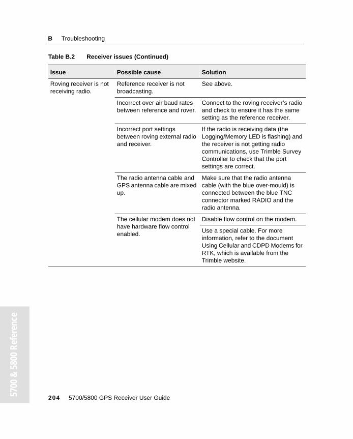
B Troubleshooting
57
00 &
580
0 Re
fere
nce
Roving receiver is not receiving radio.
Reference receiver is not broadcasting.
See above.
Incorrect over air baud rates between reference and rover.
Connect to the roving receiver’s radio and check to ensure it has the same setting as the reference receiver.
Incorrect port settings between roving external radio and receiver.
If the radio is receiving data (the Logging/Memory LED is flashing) and the receiver is not getting radio communications, use Trimble Survey Controller to check that the port settings are correct.
The radio antenna cable and GPS antenna cable are mixed up.
Make sure that the radio antenna cable (with the blue over-mould) is connected between the blue TNC connector marked RADIO and the radio antenna.
The cellular modem does not have hardware flow control enabled.
Disable flow control on the modem.
Use a special cable. For more information, refer to the document Using Cellular and CDPD Modems for RTK, which is available from the Trimble website.
Table B.2 Receiver issues (Continued)
Issue Possible cause Solution
204 5700/5800 GPS Receiver User Guide
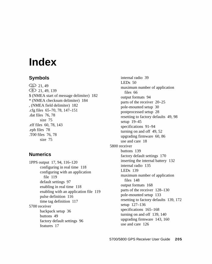
Index
Symbolsd 21, 49p 21, 49, 139$ (NMEA start of message delimiter) 182* (NMEA checksum delimiter) 184, (NMEA field delimiter) 182.cfg files 65–70, 78, 147–151.dat files 76, 78
size 75.elf files 60, 78, 143.eph files 78.T00 files 76, 78
size 75
Numerics
1PPS output 17, 94, 116–120configuring in real time 118configuring with an application
file 119default settings 97enabling in real time 118enabling with an application file 119pulse definition 116time tag definition 117
5700 receiverbackpack setup 36buttons 49factory default settings 96features 17
internal radio 39LEDs 50maximum number of application
files 66output formats 94parts of the receiver 20–25pole-mounted setup 30postprocessed setup 28resetting to factory defaults 49, 98setup 19–45specifications 91–94turning on and off 49, 52upgrading firmware 60, 86use and care 18
5800 receiverbuttons 139factory default settings 170inserting the internal battery 132internal radio 135LEDs 139maximum number of application
files 148output formats 168parts of the receiver 128–130pole-mounted setup 133resetting to factory defaults 139, 172setup 127–136specifications 165–168turning on and off 139, 140upgrading firmware 143, 160use and care 126
5700/5800 GPS Receiver User Guide 205
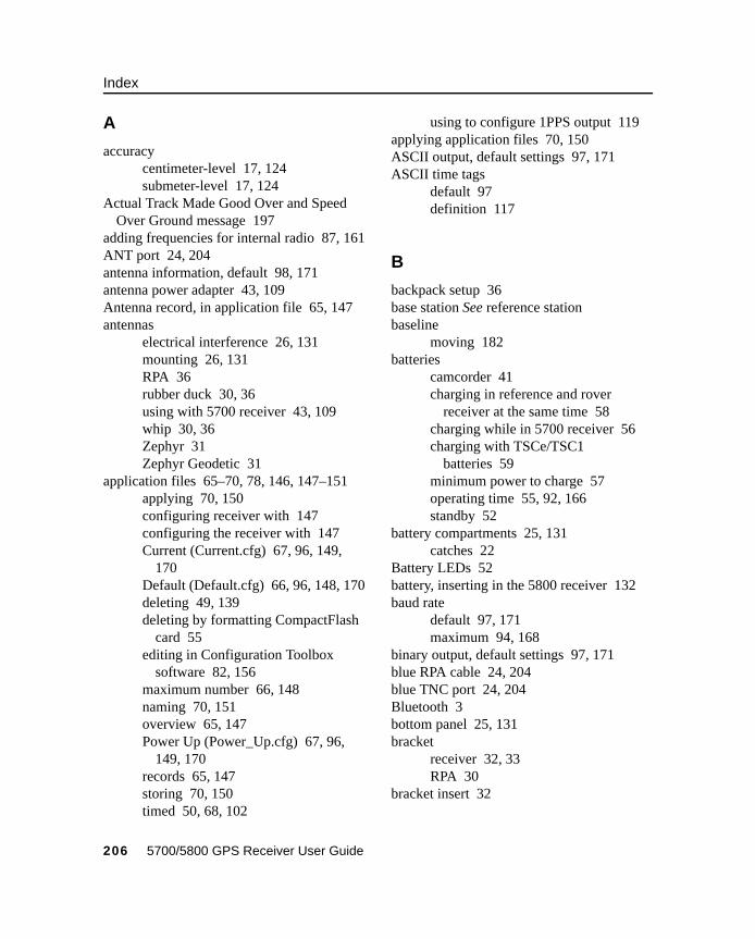
Index
A
accuracycentimeter-level 17, 124submeter-level 17, 124
Actual Track Made Good Over and Speed Over Ground message 197
adding frequencies for internal radio 87, 161ANT port 24, 204antenna information, default 98, 171antenna power adapter 43, 109Antenna record, in application file 65, 147antennas
electrical interference 26, 131mounting 26, 131RPA 36rubber duck 30, 36using with 5700 receiver 43, 109whip 30, 36Zephyr 31Zephyr Geodetic 31
application files 65–70, 78, 146, 147–151applying 70, 150configuring receiver with 147configuring the receiver with 147Current (Current.cfg) 67, 96, 149,
170Default (Default.cfg) 66, 96, 148, 170deleting 49, 139deleting by formatting CompactFlash
card 55editing in Configuration Toolbox
software 82, 156maximum number 66, 148naming 70, 151overview 65, 147Power Up (Power_Up.cfg) 67, 96,
149, 170records 65, 147storing 70, 150timed 50, 68, 102
using to configure 1PPS output 119applying application files 70, 150ASCII output, default settings 97, 171ASCII time tags
default 97definition 117
B
backpack setup 36base station See reference stationbaseline
moving 182batteries
camcorder 41charging in reference and rover
receiver at the same time 58charging while in 5700 receiver 56charging with TSCe/TSC1
batteries 59minimum power to charge 57operating time 55, 92, 166standby 52
battery compartments 25, 131catches 22
Battery LEDs 52battery, inserting in the 5800 receiver 132baud rate
default 97, 171maximum 94, 168
binary output, default settings 97, 171blue RPA cable 24, 204blue TNC port 24, 204Bluetooth 3bottom panel 25, 131bracket
receiver 32, 33RPA 30
bracket insert 32
206 5700/5800 GPS Receiver User Guide
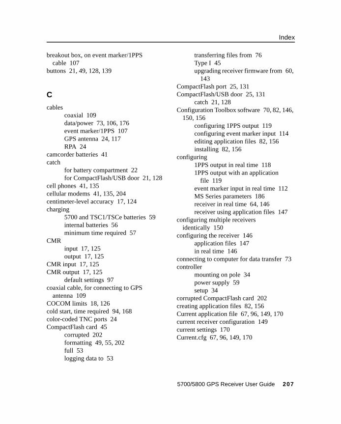
Index
breakout box, on event marker/1PPS cable 107
buttons 21, 49, 128, 139
C
cablescoaxial 109data/power 73, 106, 176event marker/1PPS 107GPS antenna 24, 117RPA 24
camcorder batteries 41catch
for battery compartment 22for CompactFlash/USB door 21, 128
cell phones 41, 135cellular modems 41, 135, 204centimeter-level accuracy 17, 124charging
5700 and TSC1/TSCe batteries 59internal batteries 56minimum time required 57
CMRinput 17, 125output 17, 125
CMR input 17, 125CMR output 17, 125
default settings 97coaxial cable, for connecting to GPS
antenna 109COCOM limits 18, 126cold start, time required 94, 168color-coded TNC ports 24CompactFlash card 45
corrupted 202formatting 49, 55, 202full 53logging data to 53
transferring files from 76Type I 45upgrading receiver firmware from 60,
143CompactFlash port 25, 131CompactFlash/USB door 25, 131
catch 21, 128Configuration Toolbox software 70, 82, 146,
150, 156configuring 1PPS output 119configuring event marker input 114editing application files 82, 156installing 82, 156
configuring1PPS output in real time 1181PPS output with an application
file 119event marker input in real time 112MS Series parameters 186receiver in real time 64, 146receiver using application files 147
configuring multiple receivers identically 150
configuring the receiver 146application files 147in real time 146
connecting to computer for data transfer 73controller
mounting on pole 34power supply 59setup 34
corrupted CompactFlash card 202creating application files 82, 156Current application file 67, 96, 149, 170current receiver configuration 149current settings 170Current.cfg 67, 96, 149, 170
5700/5800 GPS Receiver User Guide 207
Index
D
DAT files 75, 76size 75
datalogging internally 53logging to Trimble Survey
Controller 54, 141transferring from the receiver 71
Data button 21, 49data files 76, 78
deleting by formatting CompactFlash card 55
transferring from CompactFlash card 76
Data LED See Logging/Memory LEDdata link
using a cellular modem 41, 135data outputs, NMEA 186data storage cards See CompactFlash cardsdata transfer 71–78
with serial connection 73with USB connection 74
Data Transfer utilitydeleting files on receiver with 78transferring files with 75
data/power cable 106, 176pinouts 106, 176, 177
Default application file 66, 96, 148, 170default settings 96, 141, 170
1PPS time tags 97antenna 98, 171ASCII output 97, 171ASCII time tags 97baud rate 97, 171binary output 97, 171changing 149CMR output 97elevation mask 97, 171logging rate 98measurement rate 98
motion 97, 171NMEA output 97, 171overriding 148Port 3 power output 97position logging rate 98reference position 98, 171reference station 97, 171RT17 output 97, 171RTCM output 97serial format 97, 171SNR mask 97, 171streamed output 97, 171SV enabling 97, 171
Default.cfg 66, 96, 148, 170deleting files
application files 49, 139by formatting CompactFlash card 55ephemeris file 49, 139in the receiver 78
delimiters, NMEAchecksum 184field separator 184start of message 182
Device Control record, in application file 65, 147
diameter, of pole 32dimensions, of 5700 receiver 92dimensions, of 5800 receiver 166direction, NMEA field format 184disabling flow control 204dual event marker input 17, 112dual-frequency RTK engine 17, 124
E
editing application files 82, 156electrical interference 26, 131electronic interference 126elevation mask
default 97, 171
208 5700/5800 GPS Receiver User Guide
Index
enabling1PPS output in real time 1181PPS output with an application
file 119event marker input in real time 112event marker input with an application
file 114power output on Port 3 60, 143
enhanced RTK See extended RTKenvironmental factors
when setting up the receiver 26, 131ephemeris file 78
deleting 49, 139eRTK Range Pole antenna See RPAevent marker input 17, 112–115
configuring in real time 112configuring with an application
file 114Event Marker LED See Radio LEDevent marker/1PPS cable 107
pinouts 108examples, of default behavior 99extended RTK 17external power 60
minimum required to charge internal batteries 57
F
factory defaults 95–102, 169–172resetting to 49, 98, 139, 172
FastStatic surveyingspecifications 93, 167
features 1241PPS output 17automatic OTF (on-the-fly)
initialization 17, 124centimeter accuracy 17, 124charging batteries internally 17
CMR input and output 17, 125CompactFlash card 17extended RTK 17OTF data 17, 124real-time positioning 17, 124RS-232 ports 17RTCM SC-104 input and output 17,
125RTK data 17, 124submeter accuracy 17, 124USB port 17WAAS capability 17, 124
file size 75File Storage record, in application file 65,
147file types
.cfg 78
.dat 76
.elf 78
.eph 78
.T00 76application (.cfg) 78DAT 75data (.dat) 76data files 76ephemeris (.eph) 78job 54, 141raw observations (.T00) 78receiver firmware (.elf) 78supported 78
filesdeleting 78transferring from CompactFlash
card 76firmware 50, 51
upgrading 60, 86, 143, 160firmware (.elf) files 78flashing LED 50, 139flow control 94, 168
default setting 97, 171
5700/5800 GPS Receiver User Guide 209
Index
disabling on cellular modem 42, 135, 204
formatting a CompactFlash card 45, 49, 55frequencies, for internal radio 87, 161front panel 21, 128full format 202full memory 53full reset 202
G
General Controls record, in application file 65, 147
GGA message, time, position, and fix related data 186
GPS antenna cable 24GPS antenna port 17, 24, 125, 204GPS Configurator software 54, 80, 135, 146,
154configuring 1PPS output 118configuring 5700 receiver 81configuring 5800 receiver 155configuring event marker input 112deleting files on receiver with 78installing 80, 154performing a full format 202
GPS LED See SV Tracking LEDgreen LEDs 51, 52GSOF output 94GST message 188GSV message 189guidelines for setting up receiver 27, 132
H
Heading Information message 195
I
icons, on top panel 24, 130indicator LEDs 21, 50, 128, 139initialization
minimum time required 94, 168on-the-fly 17, 124specifications 94, 168
inputCMR 17, 125event marker 17, 111RTCM 17, 125
Input Message record, in application file 65, 147
insert, for receiver bracket 32installing
Configuration Toolbox software 82, 156
GPS Configurator software 80, 154WinFLASH software 85, 159
interference 26electrical 131
interference, electronic 126internal batteries
charging 17charging while in 5700 receiver 56charging with TSC1/TSCe
batteries 59minimum power to charge 57operating time 55, 92, 166standby 52
internal radio 39, 135adding frequencies 87, 161
J
job files 54, 141
210 5700/5800 GPS Receiver User Guide
Index
L
latency of 5700 receiver 93latency of 5800 receiver 167latitude, NMEA field format 184LEDs 21, 50, 128, 139
Battery 1 52Battery 2 52flashing 50, 139Logging/Memory 50Radio 51SV Tracking 51
Lemo cablesplugging in 27, 132
limits, imposed by COCOM 18, 126Lithium ion batteries
voltage 60Local Coordinate Position Output
message 193logging
internally 53scheduling 68starting 49stopping 49to Trimble Survey Controller
software 54, 141Logging button See Data buttonLogging Rate record, in application file 65,
147logging rate, default 98Logging/Memory LED 50longitude, NMEA field format 184Low Latency RTK mode
specifications 93, 167
M
maximumbaud rate 94, 168number of application files 66, 148
Maxwell architecture 94, 168measurement rate, default 98Memory LED See Logging/Memory LEDmemory, full 53, 202message ID, in NMEA messages 184mobile phones 41, 135Monitor mode 50, 51, 60, 61, 143, 200motion, default settings 97, 171mounting antenna, avoiding electrical
interference 26, 131multiple receivers
configuring identically 150
N
naming application files 70, 151NMEA
messages 186–??NMEA messages
common elements 183common message elements 184delimiters 184enabling and disabling 183GGA 187GST 188GSV 189ID 184PTNL,GGK 190PTNL,GGK_SYNC 191PTNL,PJK 193PTNL,PJT 194PTNL,VGK 194PTNL,VHD 195summary 182values 184VTG 197ZDA 198
NMEA output 17, 125, 181–198default settings 97, 171
5700/5800 GPS Receiver User Guide 211
Index
NMEA-0183 output 182
O
One Pulse per Second output See 1PPS output
on-the-fly (OTF) initialization 17, 124operating controls 128operating temperature 25, 92, 166OTF initialization See on-the-fly
initializationoutput formats 94, 168
1PPS 17, 94, 111CMR 17, 125GSOF 94NMEA 17, 125, 181RT17 94, 97, 168, 171RTCM 17, 125
Output Message record, in application file 65, 147
overriding default settings 148
P
parts of the receiver 20–25physical specifications 92, 166pinout information 174pinouts
data/power cable 106, 176, 177event marker/1PPS cable 108serial ports 105, 175
pole diameter 32using receiver bracket insert to
accommodate 32pole-mounted setup 30, 133
pole diameter 32TSC1/TSCe controller 34
Port 1connector pin locations 105
default baud rate 97, 171default serial format 97, 171event marker input 112flow control 97, 171icon 24, 130pinout diagram 105, 175pinout functions 105power output 60, 143
Port 21PPS output 112connector pin locations 105default baud rate 97, 171default serial format 97, 171event marker input 112icon 24, 130pinout diagram 105, 175pinout functions 105
Port 3connector pin locations 105default baud rate 97default power output 97default serial format 97flow control 97, 171icon 24pinout diagram 105, 175pinout functions 105power output 60, 143
port settings, checking 204Position Error Statistics message 188position logging rate, default 98positioning specifications 93, 167postprocessed setup 28power
external 60minimum to charge batteries 57
Power button 21, 49, 139power cable, pinouts 106, 176, 177Power LEDs See Battery LEDspower output
automatically enabling on Port 3 60
212 5700/5800 GPS Receiver User Guide
Index
enabling on Port 3 60, 143on Port 1 60, 143
power source 141power supply 56Power Up application file 67, 149
overriding factory defaults with 96, 170
power/data ports 23Power_Up.cfg 67, 149
overriding factory defaults with 96, 170
powering down the receiver 49, 139powering up the receiver 49, 52, 139, 140problems, troubleshooting 199–200Projection Type message 194PTNL,GGK message 190PTNL,GGK message, Time, Position,
Position Type, DOP 189PTNL,GGK_SYNC message 191PTNL,PJK message 193PTNL,PJT message 194PTNL,VGK message 194PTNL,VHD message 195pulse, for 1PPS output 116
Q
quick format 45, 54, 202
R
radio antenna port 17, 24, 125, 204Radio LED 51RADIO port 24, 204
icon 24, 130radio-modems, using 3radios 38, 134
internal 39, 135TRIMMARK 3 38, 134
TRIMMARK IIe 38, 134TRIMTALK 450S 38, 134
Range Pole antenna See RPAraw observations 78real time, configuring receiver in 64, 146real-time configuration 146rear panel 22, 129receiver
changing default settings 149configuration 146connecting to devices 174current configuration 149resetting 148
receiver bracket 32, 33receiver bracket insert 32receiver catch lock 22, 129receiver data files 76receiver firmware files 78receiver setup 19–45, 127–136receivers, multiple
configuring identically 150red LED 51Reference Position record, in application
file 65, 147reference position, default 98, 171reference receiver, charging batteries 58reference station
default 97, 171default settings 97, 171
reformatting CompactFlash card 55registration 10release notes 10reset
full 202soft 202to factory defaults 49, 98, 139, 172
resetting the receiver 148rover
charging batteries 58RPA 36
5700/5800 GPS Receiver User Guide 213
Index
RPA bracket 30RS-232 ports 17RT17 output 94, 168
default settings 97, 171RTCM input 17, 125RTCM output 17, 125
default settings 97RTK engine 17, 124RTK/OTF data 17, 124rubber duck antenna 30, 36
S
safety 4Satellite Information message 189Satellite LED See SV Tracking LEDscheduling logging sessions 68security limits 126serial format, default setting 97, 171Serial Port Baud/Format record, in
application file 65, 147serial ports 16, 17, 23
pinouts 105, 176setup 19–45, 127–136
backpack 36guidelines 26, 131pole-mounted 30, 133postprocessed survey 28TSC1/TSCe controller 34
signal processing 94, 168size, of 5700 receiver 92size, of 5800 receiver 166Sleep mode 50, 102SNR mask, default setting 97, 171soft reset 202specifications 91–94, 165–168
physical 92, 166positioning 93, 167technical 94, 168
standby, battery 52
starting loggingmanually 49
start-up specifications 94, 168Static surveying
specifications 93, 167Static/Kinematic record, in application
file 65, 147stopping logging
manually 49storage temperature 25, 92, 166storing application files 70, 150streamed output, default settings 97, 171submeter-level accuracy 17, 124supported file types 78Survey Controller software See Trimble
Survey Controller softwareSV Enable/Disable record, in application
file 65, 147SV enabling, default settings 97, 171SV Tracking LED 51switching the receiver on and off 49, 52,
139, 140Synchronized RTK mode
specifications 93, 167
T
technical specifications 94, 168temperature
operating range 25, 92, 166storage range 25, 92, 166
time tag definition 117time values in NMEA messages 185Time, Position, and Fix Related Data
message 187Time, Position, and Fix Related Data, GGA
message 186Time, Position, Position Type, DOP
message 190
214 5700/5800 GPS Receiver User Guide
Index
Time, Synchronized Position, Position Type, DOP message 191
Timed Activation record, in application file 65
timed application files 50, 68, 102TNC connector 17, 109, 125TNC ports 17, 125top panel 23tracking specifications 94, 168transferring
data files from CompactFlash card 76data files from the receiver 71
Trimble Binary Streamed Output See GSOF output
Trimble Format (CMR) See CMR formatTrimble Survey Controller software 135,
146automatically enabling power
output 60logging data to 54
Trimble web site 9, 42, 135TRIMMARK 3 radio 38, 134TRIMMARK IIe radio 38, 134TRIMTALK radio 38, 134troubleshooting 199–200TSC1/TSCe controller
deleting files on receiver with 78mounting on pole 34power supply 59setup 34
turning the receiver on and off 49, 52, 139, 140
Type approval 4Type I CompactFlash cards 17, 45types of files supported 78
U
U.S. Department of Commerce 18, 126
Universal Time Coordinated (UTC) See UTCupgrading receiver firmware 60, 86, 143,
160USB cable, connecting for data transfer 74USB port 16, 17, 25, 94, 131use and care of 5700 receiver 18use and care of 5800 receiver 126UTC Day, Month, and Year, and Local Time
Zone Offset message 198UTC, NMEA time values 185
V
Vector Information message 194voltage
minimum required to charge internal batteries 57
of internal batteries 60VTG message 197
W
WAAS 17, 124specifications 93, 167
waking up, from Sleep mode 69warm start, time required 94, 168web site 9, 42, 135weight, of 5700 receiver 92weight, of 5800 receiver 166whip antenna 30WinFLASH software 85, 135, 159
installing 85, 159upgrading receiver firmware with 86,
160world wide web site 9, 42, 135
5700/5800 GPS Receiver User Guide 215
Index
Y
yellow GPS antenna cable 24, 204yellow LEDs 50, 52yellow TNC port 24, 204
Z
ZDA message 198Zephyr antenna 31Zephyr Geodetic antenna 31
216 5700/5800 GPS Receiver User Guide

Reader Comment Form5700/5800 GPS Receiver User Guide September 2002
Revision A
We appreciate your comments and suggestions for improving this publication.
I use the following Trimble product _______________________________________for _________________________________________________________________
Please circle a response for each of the statements below:
1 = Strongly Agree 2 = Agree 3 = Neutral 4 = Disagree 5 = Strongly Disagree
The manual is well organized. 1 2 3 4 5
I can find the information I want. 1 2 3 4 5
The information in the manual is accurate. 1 2 3 4 5
I can easily understand the instructions. 1 2 3 4 5
The manual contains enough examples. 1 2 3 4 5
The examples are appropriate and helpful. 1 2 3 4 5
The layout and format are attractive and useful. 1 2 3 4 5
The illustrations are clear and helpful. 1 2 3 4 5
The manual is: too long just right too short
Please answer the following questions:
Which sections do you use the most?______________________________________What do you like best about the manual?______________________________________________________________________________________________________
What do you like least about the manual? _____________________________________________________________________________________________________
Optional
Name_______________________________________________________________Company____________________________________________________________Address ________________________________________________________________________________________________________________________________
Telephone _______________________ Fax________________________________
Please mail to Trimble Navigation Limited, 11 Birmingham Drive, P.O. Box 8729, Riccarton, Christchurch, New Zealand, Attn: Technical Publications group. Alternatively, e-mail your comments and suggestions to [email protected]. All comments and suggestions become the property of Trimble Navigation Limited.


![New Untitled Document [motorola-ua.com] 5700 LS5800... · 2012. 12. 23. · flush with the counter top. The LS 5800 is available with a stainless steel top cover and scratch-proof](https://img.pdfslide.us/doc/110x75/604300667321871f5d5df70b/new-untitled-document-motorola-uacom-5700-ls5800-2012-12-23-flush-with.jpg)