Embed Size (px)
Citation preview
570 SS
Operation and Service Manual
Manual P/N 49-053 Revision J, October 2017 From Serial Number 919


Page | I 49-053 Rev J SAPPHIRE SCIENTIFIC MODEL 570 SS
UNIT DATA LABEL
Congratulations on the purchase of your Mobile Cleaning Unit. This instruction manual is a guide for operating and
servicing your equipment. Read this manual completely before installing or operating this unit. Proper operation and service are necessary to ensure the outstanding performance of this unit. When properly maintained, your truck-mount will have a long and trouble-free life. The service methods outlined in this manual are detailed in a manner that operation and servicing may be performed properly and safely. Because service levels vary due to the skill of the mechanic, tools and parts availability, ensure that prior to attempting any maintenance or repair, you are familiar with the equipment and have all the proper tools to complete the task. Please call a Legend Brands service or customer care representative at 866-445-3030 for help with maintenance, repair, warranty and parts related questions. THIS UNIT MUST BE INSTALLED BY THE DEALER THAT YOU PURCHASED IT FROM IN ACCORDANCE WITH THE PRESCRIBED INSTALLATION PROCEDURES. Information in this document is subject to change without notice and does not represent a commitment on the part of Legend Brands.
WARRANTY REGISTRATION Thank you for purchasing a Legend Brands product. Warranty registration is quick and easy. Your registration will allow us to serve you better over the lifetime of the product.
To register your product go to: https://www.legendbrandscleaning.com/Warranty
For customer assistance: 866-445-3030

Page | II 49-053 Rev J SAPPHIRE SCIENTIFIC MODEL 570 SS
SAPPHIRE SCIENTIFIC LIMITED WARRANTY Sapphire Scientific Model 570 SS
What Does This Warranty Cover? This warranty covers the Sapphire Scientific Model 570 SS and is provided to the original purchaser only.
How Long Does This Warranty Last? This warranty runs for: Two (2) years from the date of installation on parts and labor (Excluding normal maintenance items.) Factory installed original belts are covered for 500 hours. Water box, recovery tank and frame are covered for five years. All other components including seals, o-rings and electrical components are covered for the entire two year warranty period.
What Sapphire Scientific Will Do: If a defect in materials or workmanship occurs within the warranty period, Sapphire Scientific at its election will repair or replace the defective part at no charge.
What This Warranty Does Not Cover: This warranty does not cover or apply to defects due directly or indirectly to misuse, abuse, disassembly, alteration, corrosive chemicals, improper voltage, improper fuel, fire, flood, negligence, accident, improperly or incorrectly performed maintenance or repair, or failure to perform necessary or recommended maintenance or repair (See your Owner’s Manual) or if the use of this product is not in compliance with the instructions and specifications for its use. This warranty does not cover normal maintenance items such as air and oil filters, lubricants and tune up parts. Paint is not covered. Water box, recovery tank and frame are covered for five years. All other components including seals, o-rings and electrical components are covered for the entire two year warranty period. We limit all implied warranties to: Two (2) years from the installation date on parts and labor. It is strongly recommended that this truck mount be used with, and only with, Sapphire Scientific recommended chemicals and as directed by label instructions on chemical bottles.
OTHER THAN THE WARRANTIES PROVIDED HEREIN, SAPPHIRE SCIENTIFIC MAKES NO EXPRESS OR IMPLIED, ORAL OR WRITTEN WARRANTIES WITH RESPECT TO THIS PRODUCT OR WORKMANSHIP AND ALL WARRANTIES IMPLIED BY LAW INCLUDING ANY WARRANTIES OF MERCHANTABILITY OR FITNESS FOR A PARTICULAR PURPOSE ARE LIMITED TO THE DURATION OF THIS WARRANTY. Some states do not allow limitations on how long an implied warranty lasts, so the above limitations may not apply to you. WE SHALL IN NO EVENT BE LIABLE FOR DEATH, INJURIES TO PERSONS OR PROPERTY OR FOR INCIDENTAL, CONTINGENT, SPECIAL OR CONSEQUENTIAL DAMAGES ARISING FROM USE OF OUR PRODUCTS. Some states do not allow the exclusion or limitation of incidental or consequential damages, so the above limitation or exclusion may not apply to you.
How Do I Get Service? In order to be eligible for service under this warranty you MUST do the following: (a) fill out the warranty registration card on-line within thirty (30) days of the installation of our product; (b) write or call a service representative at Sapphire Scientific for a return material authorization (RMA); and (c) have the serial number available. Proof of proper maintenance may be required before warranty is granted.
Contact us at: Sapphire Scientific
2604 Liberator, Prescott, AZ 86301 Phone: 928-445-3030 / 866-445-3030
If Sapphire Scientific uncovers a defect we will repair or replace the product, at our election. Ground shipping and transportation costs will be covered by the manufacturer. Returning defective parts to the manufacturer, if required, shall be the responsibility of the purchaser. Warranty may be denied if defective parts are not returned within 90 days. If it is determined that there is no defect in the product, or that the defect resulted from causes not within the scope of our warranty, then the product will be repaired or replaced only at your request and at your expense and you must bear all shipping costs.
How Does State Law Apply? This warranty gives you specific legal rights, and you may also have other rights which vary from state to state.
Page | III 49-053 Rev J SAPPHIRE SCIENTIFIC MODEL 570 SS
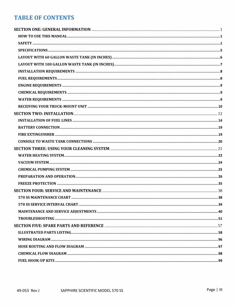
TABLE OF CONTENTS SECTION ONE: GENERAL INFORMATION ........................................................................................................................ 1
HOW TO USE THIS MANUAL ...................................................................................................................................................... 1
SAFETY ........................................................................................................................................................................................ 1
SPECIFICATIONS ......................................................................................................................................................................... 5
LAYOUT WITH 60 GALLON WASTE TANK (IN INCHES) .......................................................................................................... 6
LAYOUT WITH 100 GALLON WASTE TANK (IN INCHES) ........................................................................................................ 7
INSTALLATION REQUIREMENTS .............................................................................................................................................. 8
FUEL REQUIREMENTS ................................................................................................................................................................ 8
ENGINE REQUIREMENTS ........................................................................................................................................................... 9
CHEMICAL REQUIREMENTS ...................................................................................................................................................... 9
WATER REQUIREMENTS ........................................................................................................................................................... 9
RECEIVING YOUR TRUCK-MOUNT UNIT ................................................................................................................................ 10
SECTION TWO: INSTALLATION ....................................................................................................................................... 12
INSTALLATION OF FUEL LINES ............................................................................................................................................... 14
BATTERY CONNECTION ........................................................................................................................................................... 19
FIRE EXTINGUISHER ................................................................................................................................................................ 19
CONSOLE TO WASTE TANK CONNECTIONS ........................................................................................................................... 20
SECTION THREE: USING YOUR CLEANING SYSTEM ..................................................................................................... 21
WATER HEATING SYSTEM ....................................................................................................................................................... 22
VACUUM SYSTEM...................................................................................................................................................................... 24
CHEMICAL PUMPING SYSTEM ................................................................................................................................................. 25
PREPARATION AND OPERATION............................................................................................................................................ 26
FREEZE PROTECTION .............................................................................................................................................................. 35
SECTION FOUR: SERVICE AND MAINTENANCE ............................................................................................................ 38
570 SS MAINTENANCE CHART ................................................................................................................................................ 38
570 SS SERVICE INTERVAL CHART ......................................................................................................................................... 39
MAINTENANCE AND SERVICE ADJUSTMENTS ....................................................................................................................... 40
TROUBLESHOOTING ................................................................................................................................................................ 51
SECTION FIVE: SPARE PARTS AND REFERENCE .......................................................................................................... 57
ILLUSTRATED PARTS LISTING ................................................................................................................................................ 58
WIRING DIAGRAM .................................................................................................................................................................... 96
HOSE ROUTING AND FLOW DIAGRAM ................................................................................................................................... 97
CHEMICAL FLOW DIAGRAM .................................................................................................................................................... 98
FUEL HOOK-UP KITS ................................................................................................................................................................ 99

SECTION ONE: GENERAL INFORMATION
P a g e | 1 49-038 Rev G SAPPHIRE SCIENTIFIC 370 SS
SECTION ONE: GENERAL INFORMATION
HOW TO USE THIS MANUAL This manual contains the following sections:
How to Use This Manual
Safety
Installation
Operation
Maintenance & Service
Parts Listing & Diagrams The HOW TO USE THIS MANUAL section will tell you how to find important information for ordering correct repair parts. Parts may be ordered from authorized dealers. When placing an order for parts, the machine model and machine serial number are important. Refer to the MACHINE DATA box which is filled out during the installation of your machine. The MACHINE DATA box is located on the inside of the front cover of this manual.
The model and serial number of your unit is located on the front left side of the frame as shown here:
The SAFETY section contains important information regarding hazardous or unsafe practices for this machine. Levels of hazards are identified that could result in product damage, personal injury, or severe injury resulting in death. The INSTALLATION section contains information on how to properly install the unit in your vehicle.
The OPERATION section is to familiarize the operator with the operation and function of the machine. The MAINTENANCE section contains preventive maintenance to keep the machine and its components in good working condition. The PARTS LISTING & DIAGRAMS section contains assembled parts illustrations and corresponding parts list. The parts lists include a number of columns of information: NOTE: If a service or option kit is installed on your machine, be sure to keep the KIT INSTRUCTIONS which came with the kit. It contains replacement parts numbers needed for ordering future parts.
SECTION ONE: GENERAL INFORMATION
P a g e | 1
49-053 Rev J SAPPHIRE SCIENTIFIC MODEL 570 SS
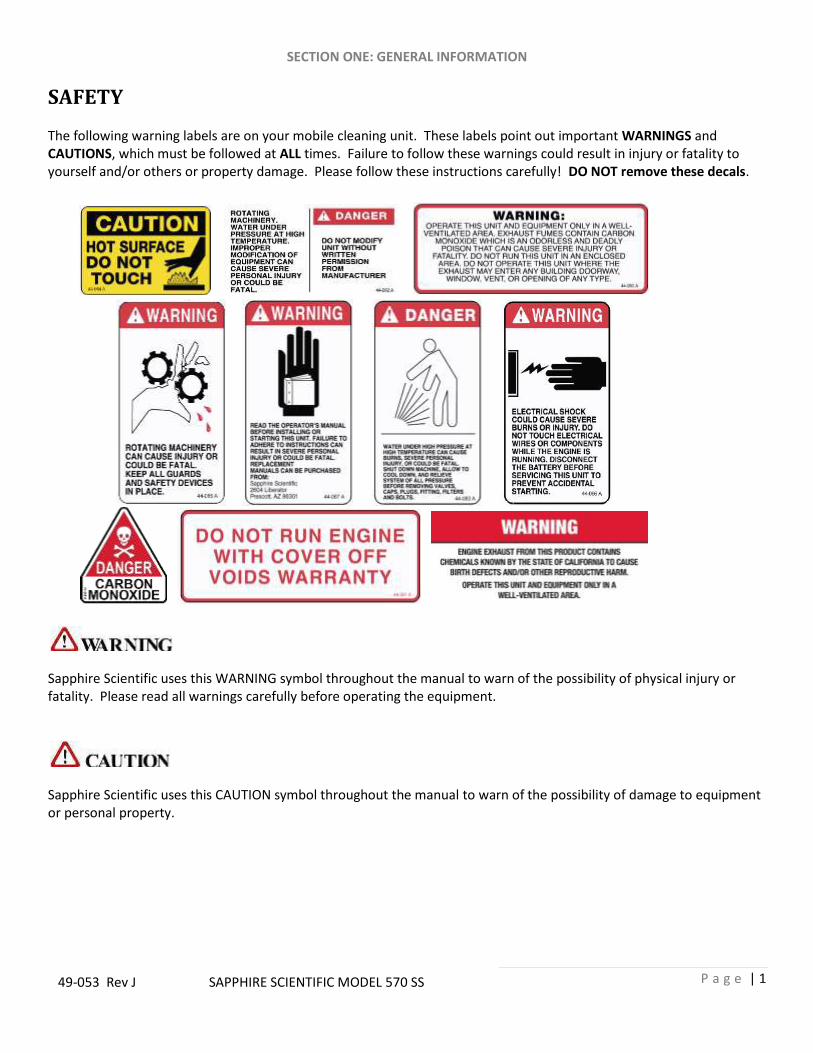
SAFETY The following warning labels are on your mobile cleaning unit. These labels point out important WARNINGS and CAUTIONS, which must be followed at ALL times. Failure to follow these warnings could result in injury or fatality to yourself and/or others or property damage. Please follow these instructions carefully! DO NOT remove these decals.
Sapphire Scientific uses this WARNING symbol throughout the manual to warn of the possibility of physical injury or fatality. Please read all warnings carefully before operating the equipment.
Sapphire Scientific uses this CAUTION symbol throughout the manual to warn of the possibility of damage to equipment or personal property.
SECTION ONE: GENERAL INFORMATION
P a g e | 2
49-053 Rev J SAPPHIRE SCIENTIFIC MODEL 570 SS
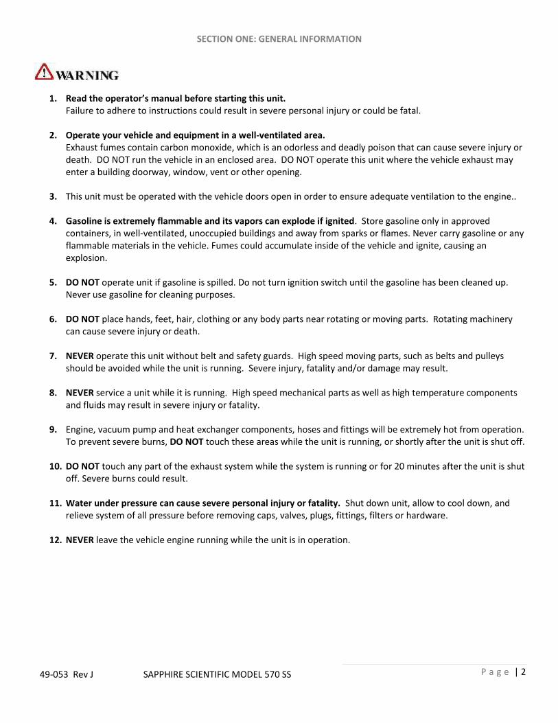
1. Read the operator’s manual before starting this unit. Failure to adhere to instructions could result in severe personal injury or could be fatal.
2. Operate your vehicle and equipment in a well-ventilated area.
Exhaust fumes contain carbon monoxide, which is an odorless and deadly poison that can cause severe injury or death. DO NOT run the vehicle in an enclosed area. DO NOT operate this unit where the vehicle exhaust may enter a building doorway, window, vent or other opening.
3. This unit must be operated with the vehicle doors open in order to ensure adequate ventilation to the engine..
4. Gasoline is extremely flammable and its vapors can explode if ignited. Store gasoline only in approved
containers, in well-ventilated, unoccupied buildings and away from sparks or flames. Never carry gasoline or any flammable materials in the vehicle. Fumes could accumulate inside of the vehicle and ignite, causing an explosion.
5. DO NOT operate unit if gasoline is spilled. Do not turn ignition switch until the gasoline has been cleaned up.
Never use gasoline for cleaning purposes.
6. DO NOT place hands, feet, hair, clothing or any body parts near rotating or moving parts. Rotating machinery can cause severe injury or death.
7. NEVER operate this unit without belt and safety guards. High speed moving parts, such as belts and pulleys
should be avoided while the unit is running. Severe injury, fatality and/or damage may result.
8. NEVER service a unit while it is running. High speed mechanical parts as well as high temperature components and fluids may result in severe injury or fatality.
9. Engine, vacuum pump and heat exchanger components, hoses and fittings will be extremely hot from operation.
To prevent severe burns, DO NOT touch these areas while the unit is running, or shortly after the unit is shut off.
10. DO NOT touch any part of the exhaust system while the system is running or for 20 minutes after the unit is shut off. Severe burns could result.
11. Water under pressure can cause severe personal injury or fatality. Shut down unit, allow to cool down, and
relieve system of all pressure before removing caps, valves, plugs, fittings, filters or hardware.
12. NEVER leave the vehicle engine running while the unit is in operation.
SECTION ONE: GENERAL INFORMATION
P a g e | 3
49-053 Rev J SAPPHIRE SCIENTIFIC MODEL 570 SS
13. Battery acid contains sulfuric acid. To prevent acid burns, avoid contact with skin, eyes and clothing. Batteries also produce explosive hydrogen gases while charging. To prevent fire or explosion, charge batteries only in a well ventilated area. Keep sparks, open flames, as well as other sources of ignition away from battery at all times. Remove all jewelry prior to servicing batteries. Keep batteries out of the reach of children. Before disconnecting the negative (−) ground cable, ensure that all switches are in the off position. If on, a spark could occur at the ground connection terminal which could cause an explosion if hydrogen gas or gasoline vapors are present. ALWAYS disconnect the negative (−) terminal first
14. DO NOT smoke around the vehicle. Gas fumes could accumulate and ignite. Battery gasses are extremely
flammable. This will prevent possible explosions.
15. NEVER cut or splice any of the vehicle fuel lines during fuel line installation. This will result in fuel leaks and potentially dangerous conditions. Use only the provided fuel hose for fuel lines. When going through the vehicle floor with fuel lines, always utilize bulkhead adaptors. This will prevent fuel leaks and ensure that hoses are not punctured by vehicle vibration abrasion.
16. All high-pressure hoses must be rated at 250° F and 3000 PSI. Severe injuries may result from improper hoses.
17. The Occupational and Health Administration (OSHA) recommends the use of hearing protection when a technician is exposed to an average of 85 decibels (this is an average of exposure over an 8 hour period). This equipment can produce 85 decibels at a distance of 10 feet. Please check with your local state agencies to see if OSHA standards apply to your application.
18. This unit produces high solution pressure. Improper use could result in injury.
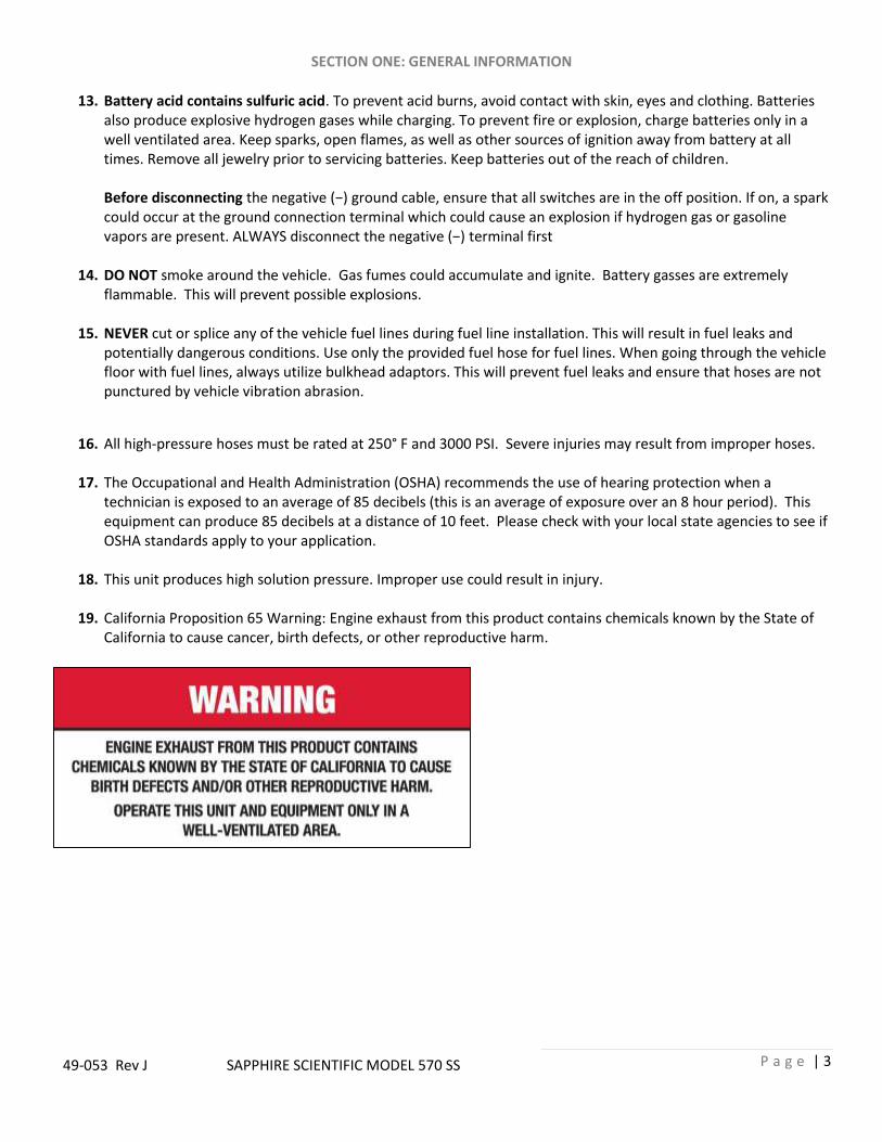
19. California Proposition 65 Warning: Engine exhaust from this product contains chemicals known by the State of
California to cause cancer, birth defects, or other reproductive harm.

SECTION ONE: GENERAL INFORMATION
P a g e | 4
49-053 Rev J SAPPHIRE SCIENTIFIC MODEL 570 SS
1. DO NOT damage the vehicle in any way during the installation. Avoid component or hose contact with moving parts, hot surfaces, brake lines, fuel lines, catalytic converters, exhaust pipes, mufflers, rotating parts or sharp objects.
2. DO NOT exceed the vehicle’s payload capacity. This will prevent unsafe or hazardous driving conditions. Before
installing any components into the vehicle, check with the vehicle manufacturer for the Gross Vehicle Weight Rating (GVWR). GVWR is the maximum allowable combined weight of the vehicle, including all passengers, fuel, fluids, tools and cargo. Example: If the GVWR for a vehicle is 9600 lbs. and the vehicle has a base curb weight of 6406 lbs., this leaves a payload capacity of 3194 lbs. (GVWR - Curb Weight = Payload Capacity).
3. Always keep your vehicle clean and orderly. Tools and accessories must be securely stowed while driving the
vehicle.
4. Ensure that you have received proper training and are familiar with the start-up and shut-down procedures prior to operation.
5. DO NOT alter or modify your Model 570 SS in any way. Use only replacement parts authorized by Sapphire Scientific. Modifications or use of unapproved parts could create a hazard and will void your warranty. This includes the use of any open ended hoses.
6. Failure to apply preventative measures towards freezing can result in system failure and loss of warranty on
affected parts. Water freezes at 32° F and 0° C.
READ AND SAVE THESE INSTRUCTIONS

SECTION ONE: GENERAL INFORMATION
P a g e | 5
49-053 Rev J SAPPHIRE SCIENTIFIC MODEL 570 SS
SPECIFICATIONS
Engine Speed 3000 RPM (High Speed/No Load)
1500 RPM (Idle/No Load)
Water Pump 1500 RPM (High Speed)
Water Pump Flow Rate 5 GPM (Maximum)
Water Pump Pressure 1500 PSI (Maximum)
Vacuum Pump 3000 RPM (High Speed)
Vacuum Relief Valve 13 in. Hg
Waste Tank Capacity at Shut-Off 75 gallons
Waste Tank Gross Capacity 100 gallons
Console Weight 1056 lbs. (dry)
Standard Install Package Weight 1454 lbs. (dry)
Operating Weight 2200 lbs. (includes water weight, not accessories)
TORQUE VALUES Engine Crankshaft Hub 40 lbf·ft
Engine Fan Mounting Bolt 7 - 8 lbf·ft
Engine Front Lower Pulley Bolt 69 lbf·ft
Vacuum Pump Hub 13 lbf·ft
JET SIZING Sapphire Scientific recommends that the total floor tool tip size be #6

SECTION ONE: GENERAL INFORMATION
P a g e | 6
49-053 Rev J SAPPHIRE SCIENTIFIC MODEL 570 SS
LAYOUT WITH 60 GALLON WASTE TANK (IN INCHES)
SECTION ONE: GENERAL INFORMATION
P a g e | 7
49-053 Rev J SAPPHIRE SCIENTIFIC MODEL 570 SS
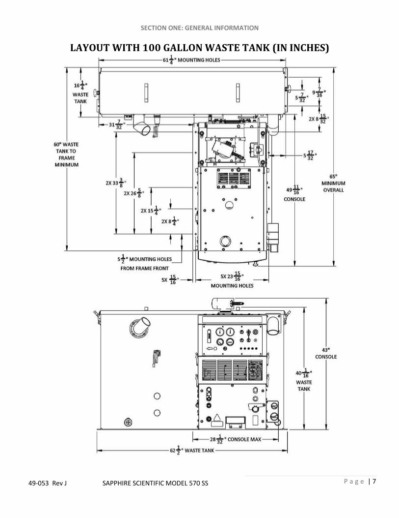
LAYOUT WITH 100 GALLON WASTE TANK (IN INCHES)

SECTION ONE: GENERAL INFORMATION
P a g e | 8
49-053 Rev J SAPPHIRE SCIENTIFIC MODEL 570 SS
INSTALLATION REQUIREMENTS Prior to beginning the installation, read the ENTIRE “Installation” section of this manual. Since the MODEL 570 SS truck mount weighs (with waste tank and accessories) 1454 lbs., please adhere to the following recommendations prior to installing the unit.
1. The unit should NOT be installed in any motor vehicle rated less than 3/4 ton capacity.
! DO NOT exceed the vehicle’s payload capacity. This will prevent unsafe or hazardous driving conditions. Before installing any components into the vehicle, check with the vehicle manufacturer for the Gross Vehicle Weight Rating (GVWR). GVWR is the maximum allowable combined weight of the vehicle, including all passengers, fuel, fluids, tools and cargo.
2. If mounting the unit in a trailer, ensure that the trailer is rated for the total weight of the unit and trailer. Electric or hydraulic brakes must be provided, and strict compliance with all State and Federal laws must be maintained.
3. If mounting in a trailer, the MODEL 570 SS console must be positioned so that it balances properly with respect
to the trailer axle. Ten percent (10%) of the unit’s total overall weight (w/o accessories or water) should be on the tongue. This unit has an air cooled engine, and adequate ventilation must be provided to prevent overheating.
4. Sapphire Scientific does not recommend using any type of flooring materials that absorb water. This condition
will result in rust and corrosion of the vehicle floor.
5. Insulation under rubber mats should be removed prior to installation of the unit.
FUEL REQUIREMENTS Use unleaded fuel ONLY. Use only fresh, clean unleaded gasoline with a minimum octane rating of 87. Do Not use high octane gasoline. Gasoline with up to, not exceeding, 10% ethanol is acceptable. NOTE: Using other gasoline/alcohol blends including E20 and E85 will cause damage to engine components and will void warranty.

SECTION ONE: GENERAL INFORMATION
P a g e | 9
49-053 Rev J SAPPHIRE SCIENTIFIC MODEL 570 SS
ENGINE REQUIREMENTS Use high-quality oil of at least API (American Petroleum Institute) service class SG or higher. Do not use additives. High quality 30W oil is recommended. It is never recommended to extend oil change intervals past 200 hours
Engine Oil Capacity 3.4 L 3.59 US qts
Tightening Torque
Drain Plug 33 – 37 N·m 3 – 4 kgf·m 24 – 27 lbf·ft
CHEMICAL REQUIREMENTS
The SAPPHIRE SCIENTIFIC MODEL 570 SS Truck mount unit’s unique last step chemical injection system can be used with a wide variety of water diluted chemical compounds, either acidic or alkaline, depending on the work to be performed. We recommend using only SAPPHIRE SCIENTIFIC brand chemistry.
WATER REQUIREMENTS Because hard water deposits will damage the plumbing and heat exchange systems on this unit, Sapphire Scientific recommends that a high quality water softener be used in areas where the water hardness exceeds 3½ grains. If a water softener is used, it must have a flow capacity of at least five (5) GPM or greater, without any hose constrictions. The use of a water softening system will reduce maintenance and reduce down time caused by hard water scaling. It will also enhance the performance of cleaning chemicals, which will result in greater efficiency in lower concentrations.
NOTE: Using lower service class oil or extending oil change intervals longer than recommended can cause engine damage.

SECTION ONE: GENERAL INFORMATION
P a g e | 10
49-053 Rev J SAPPHIRE SCIENTIFIC MODEL 570 SS
RECEIVING YOUR TRUCK-MOUNT UNIT
DEALER RESPONSIBILITIES
The sapphire scientific authorized dealer that you purchased this unit from is responsible for:
1. Correctly installing and properly securing equipment with proper hardware and underside mounting plates. 2. Checking the components and oil levels prior to starting the unit. 3. Checking that all components are operating at the factory specification. 4. Checking all hoses and accessories for correct operation. 5. Checking all tools/wands for correct operation. 6. Training you in the operation, maintenance and safety precautions of your unit.
It is the purchaser’s responsibility to become familiar with the entire Owner’s Manual, most importantly all Warnings, Cautions and Notices.
ACCEPTANCE OF SHIPMENT Your model 570 SS truck-mount was thoroughly tested, checked and inspected in its entirety prior to leaving our manufacturing facility. When receiving your unit, please make the following acceptance check:
1. The unit should not show any signs of damage. If there is damage, notify the deliverer immediately. 2. Carefully check your equipment. The model 570 SS should arrive with the following items as well as any
additional optional accessories you may have ordered:
EQUIPMENT LISTING
Sapphire Scientific 570 console
Recovery tank with shut-off switch
Recovery tank vacuum hoses
Operation and Service Manual
Installation mounting plates and hardware
Hose clamps for vacuum, water and fuel hoses
Two recovery tank mesh filters and stainless steel strainer basket
100 ft. of 1/4-inch high pressure solution hose with shutoff valve and quick connects
50 ft. of 1/4-inch high pressure solution hose with quick connects
150 ft. of 2-inch vacuum hose
50 ft. water supply hose with quick connect

SECTION ONE: GENERAL INFORMATION
P a g e | 11
49-053 Rev J SAPPHIRE SCIENTIFIC MODEL 570 SS
OPTIONAL EQUIPMENT
50 ft. 2-inch vacuum hose Part No. 18-003
50 ft. 2-1/2-inch vacuum hose Part No. 18-333
2-inch vacuum hose coupler Part No. 21-003
50 ft. high-pressure solution hose with qd fittings (no valve) Part No. 18-000
100 ft. high-pressure solution hose w/valve and qd fittings Part No. 18-250
50 ft. water hose w/qd fitting Part No. 18-002
Automatic waste pump kit Part No. 68-158
Demand pump system
Part No. 68-190
FUEL HOOK-UP KITS BY VEHICLE Chevy 1997 to 2002 FI 69-003FI
Chevy 2003 FI 69-018FI
Chevy 2004+ Hook-Up Kit 69-033
Chevy Box Truck 2004+ 69-081
Dodge 1997 to 2002 FI 69-004FI
Ford FI 69-005FI
Ford 2004 – 2010 69-061
Ford 2011+ 69-331
Ford Box Truck 2004+ 68-077
Ford Transit Connect 69-261S
Nissan NV 69-376
SECTION TWO: INSTALLATION
P a g e | 12
49-053 Rev J SAPPHIRE SCIENTIFIC MODEL 570 SS
SECTION TWO: INSTALLATION
!!! This unit must be bolted to the floor of the vehicle by an authorized SAPPHIRE SCIENTIFIC DISTRIBUTOR.
LIFTING THE UNIT INTO THE VEHICLE Because the console weighs approximately 1056 lbs., a forklift is necessary to place the unit into the vehicle. Place the forks under the unit. Using two “C” clamps, secure the console to the forks. Move the unit into desired position.
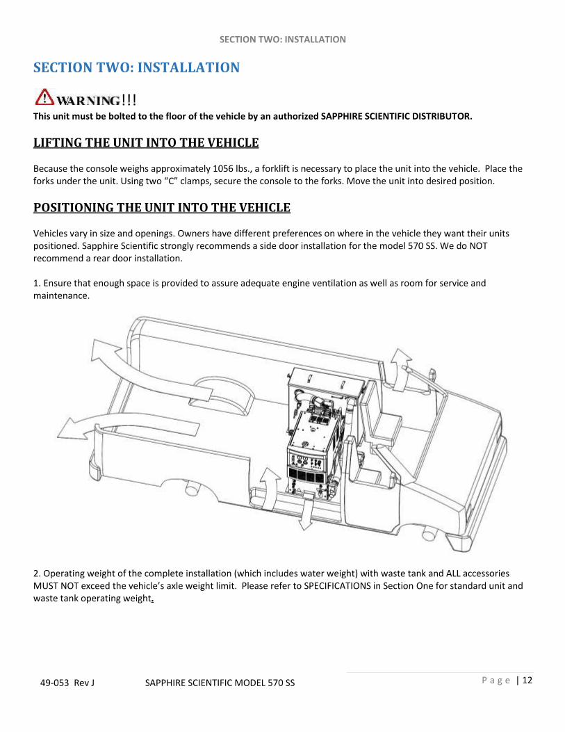
POSITIONING THE UNIT INTO THE VEHICLE Vehicles vary in size and openings. Owners have different preferences on where in the vehicle they want their units positioned. Sapphire Scientific strongly recommends a side door installation for the model 570 SS. We do NOT recommend a rear door installation. 1. Ensure that enough space is provided to assure adequate engine ventilation as well as room for service and maintenance.
2. Operating weight of the complete installation (which includes water weight) with waste tank and ALL accessories MUST NOT exceed the vehicle’s axle weight limit. Please refer to SPECIFICATIONS in Section One for standard unit and waste tank operating weight.
SECTION TWO: INSTALLATION
P a g e | 13
49-053 Rev J SAPPHIRE SCIENTIFIC MODEL 570 SS
FASTENING DOWN THE UNIT AND WASTE TANK
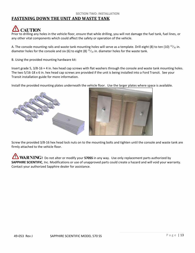
Prior to drilling any holes in the vehicle floor, ensure that while drilling, you will not damage the fuel tank, fuel lines, or any other vital components which could affect the safety or operation of the vehicle. A. The console mounting rails and waste tank mounting holes will serve as a template. Drill eight (8) to ten (10) 13⁄32 in. diameter holes for the console and six (6) to eight (8) 13⁄32 in. diameter holes for the waste tank. B. Using the provided mounting hardware kit: Insert grade 5, 3/8-16 × 4 in. hex head cap screws with flat washers through the console and waste tank mounting holes. The two 5/16-18 x 6 in. hex head cap screws are provided if the unit is being installed into a Ford Transit. See your Transit installation guide for more information. Install the provided mounting plates underneath the vehicle floor. Use the larger plates where space is available.
Screw the provided 3/8-16 hex head lock nuts on to the mounting bolts and tighten until the console and waste tank are firmly attached to the vehicle floor.
! Do not alter or modify your 570SS in any way. Use only replacement parts authorized by SAPPHIRE SCIENTIFIC, Inc. Modifications or use of unapproved parts could create a hazard and will void your warranty. Contact your authorized Sapphire dealer for assistance.

SECTION TWO: INSTALLATION
P a g e | 14
49-053 Rev J SAPPHIRE SCIENTIFIC MODEL 570 SS
INSTALLATION OF FUEL LINES
! The Vehicle fuel lines should NOT be spliced under ANY circumstances. Severe injury or fatality
could result.
When routing fuel lines, DO NOT configure the hoses in any location where the hoses, or vehicle could be damaged.
All fuel lines must meet CARB TIER III and EPA PHASE 3 low permeability requirements.
Avoid contact with moving parts, areas of high temperature, brake lines, fuel lines, catalytic converters, exhaust pipes, mufflers or sharp objects.
Fuel pump must be mounted in a vertical position as near as possible to the fuel supply, and not located near any heat sources.
Excess heat from exhaust or other heat sources may cause the fuel pump to work improperly.
FUEL LINE BULKHEAD INSTALLATION
1. Inside the vehicle, select an appropriate location on the vehicle floor away from operator or maintenance traffic and away from contact with any accessories or tools while in use or transit. Make sure your hole is within adequate reach of the supplied hose in the finished assembly.
2. Drill a 3/4 inch hole through the vehicle floor at the location chosen for the bulkhead connector. 3. Install the bulkhead connector by inserting the fitting and tightening the nut and lock washer on the opposite
side of the vehicle floor. 4. Inside the vehicle, attach the hose barb fitting and connect the fuel line from the console. 5. Drill a 1/2 inch hole nearby the bulkhead fitting for the fuel pump electrical extension harness to pass through.
SEE DIAGRAM ON NEXT PAGE

SECTION TWO: INSTALLATION
P a g e | 15
49-053 Rev J SAPPHIRE SCIENTIFIC MODEL 570 SS
FUEL LINE BULKHEAD INSTALLATION DIAGRAM

SECTION TWO: INSTALLATION
P a g e | 16
49-053 Rev J SAPPHIRE SCIENTIFIC MODEL 570 SS
FUEL PUMP ASSEMBLY INSTALLATION Locate an appropriate location for the fuel pump assembly housing to mount underneath the vehicle that will not cause damage to the vehicle or compromise the fuel line routing or components. Remove the housing lid from the fuel pump assembly. Use the supplied Tek screws to install the lid of the fuel pump housing to the vehicle. NOTE: Install the fuel pump assembly close to the fuel source.
SECTION TWO: INSTALLATION
P a g e | 17
49-053 Rev J SAPPHIRE SCIENTIFIC MODEL 570 SS
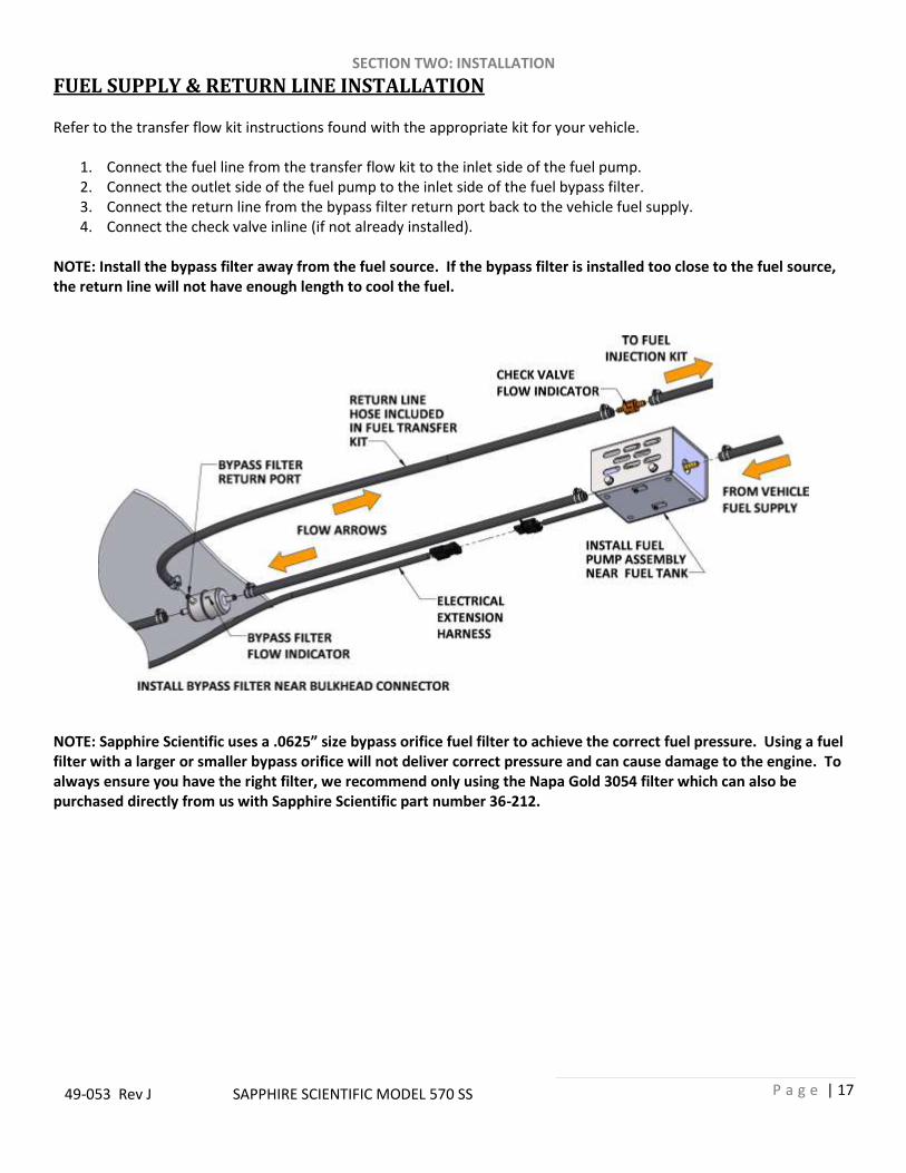
FUEL SUPPLY & RETURN LINE INSTALLATION Refer to the transfer flow kit instructions found with the appropriate kit for your vehicle.
1. Connect the fuel line from the transfer flow kit to the inlet side of the fuel pump. 2. Connect the outlet side of the fuel pump to the inlet side of the fuel bypass filter. 3. Connect the return line from the bypass filter return port back to the vehicle fuel supply. 4. Connect the check valve inline (if not already installed).
NOTE: Install the bypass filter away from the fuel source. If the bypass filter is installed too close to the fuel source, the return line will not have enough length to cool the fuel.
NOTE: Sapphire Scientific uses a .0625” size bypass orifice fuel filter to achieve the correct fuel pressure. Using a fuel filter with a larger or smaller bypass orifice will not deliver correct pressure and can cause damage to the engine. To always ensure you have the right filter, we recommend only using the Napa Gold 3054 filter which can also be purchased directly from us with Sapphire Scientific part number 36-212.

SECTION TWO: INSTALLATION
P a g e | 18
49-053 Rev J SAPPHIRE SCIENTIFIC MODEL 570 SS
5. Attach the 90 degree elbow and hose barb fittings to the bulkhead connector underneath the vehicle. 6. Connect a segment of hose between the outlet side of the fuel bypass filter to the hose barb fitting. 7. Ensure that all hose clamps are properly tightened. 8. Connect the electrical extension harness to the fuel pump harness, running the other end up through a hole in
the floor of the vehicle, connecting to the console harness.
TRAILER FUEL TANK AND FUEL LINE INSTALLATION
The following are recommendations for trailer installations:
Strict compliance with all federal and state laws must be maintained. Tanks must meet CARB TIER III and EPA PHASE3 permeation and venting emissions requirements.
Use only fuel tanks that are manufactured specifically for gasoline, have proper vented filling caps, and outlet connections that are the same size as the inlet and return connections on the unit.
DO NOT install fuel tanks inside any type of enclosed trailer or vehicle.
NEVER carry gasoline or flammable materials in an enclosed trailer or vehicle.
NEVER store any type of flammable material in an enclosed trailer or vehicle.
Always mount fuel tanks where they will be protected from any vehicle collision.
When installing fuel lines from the fuel tank to the unit, use the proper size fuel line.

SECTION TWO: INSTALLATION
P a g e | 19
49-053 Rev J SAPPHIRE SCIENTIFIC MODEL 570 SS
BATTERY CONNECTION
! Explosive gases, Dangerous gases! Batteries contain sulfuric acid. To prevent acid burns, avoid contact with skin, eyes and clothing. Batteries also produce explosive hydrogen gases while charging. To prevent fire or explosion, charge batteries in a well-ventilated area only. Keep sparks, open flames, as well as any other sources of ignition away from batteries at all times. Remove all jewelry prior to servicing batteries. Keep batteries out of the reach of children.
Before disconnecting the negative (−) ground cable, ensure that all switches are in the OFF position. If ON a spark could occur at the ground connection terminal, which could cause an explosion if hydrogen gas or gasoline vapors are present. ALWAYS disconnect the negative (−) terminal first.
Attach the red positive (+) battery cable from the starter solenoid on the console to the positive (+) terminal on the battery and tighten down the nut.
Attach the black negative (−) battery cable from the ground on the console to the negative (−) terminal on the battery and tighten down the nut
FIRE EXTINGUISHER SAPPHIRE SCIENTIFIC, and many government agencies, recommend that a fire extinguisher rated for A, B, and C type fires be installed into any commercial vehicle.

SECTION TWO: INSTALLATION
P a g e | 20
49-053 Rev J SAPPHIRE SCIENTIFIC MODEL 570 SS
CONSOLE TO WASTE TANK CONNECTIONS

SECTION THREE: USING YOUR CLEANING SYSTEM
P a g e | 21
49-053 Rev J SAPPHIRE SCIENTIFIC MODEL 570 SS
SECTION THREE: USING YOUR CLEANING SYSTEM
UNDERSTANDING THE SYSTEMS
NOTE: Read and understand this section of the manual entirely before proceeding. This portion of the manual divides the unit up into systems and describes how each system works. Prior to proceeding into the operations and maintenance sections of this manual it is recommended that you acquire a basic understanding of how the unit functions.
SECTION THREE: USING YOUR CLEANING SYSTEM
P a g e | 22
49-053 Rev J SAPPHIRE SCIENTIFIC MODEL 570 SS
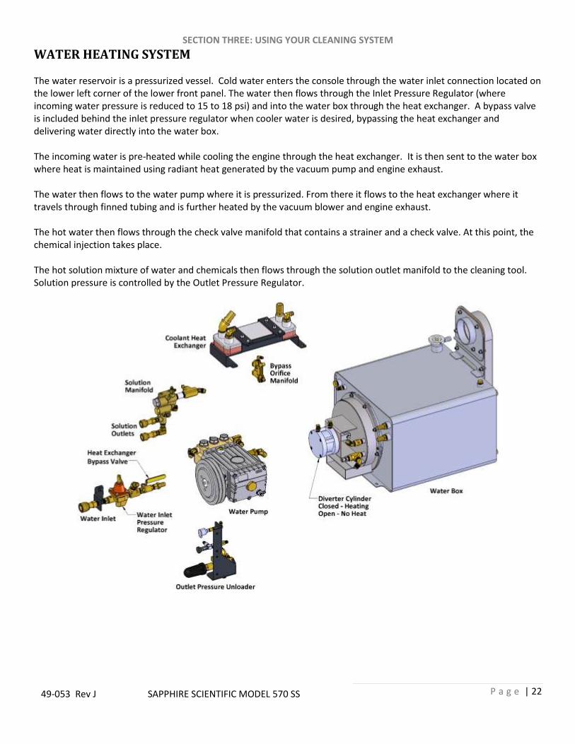
WATER HEATING SYSTEM The water reservoir is a pressurized vessel. Cold water enters the console through the water inlet connection located on the lower left corner of the lower front panel. The water then flows through the Inlet Pressure Regulator (where incoming water pressure is reduced to 15 to 18 psi) and into the water box through the heat exchanger. A bypass valve is included behind the inlet pressure regulator when cooler water is desired, bypassing the heat exchanger and delivering water directly into the water box. The incoming water is pre-heated while cooling the engine through the heat exchanger. It is then sent to the water box where heat is maintained using radiant heat generated by the vacuum pump and engine exhaust. The water then flows to the water pump where it is pressurized. From there it flows to the heat exchanger where it travels through finned tubing and is further heated by the vacuum blower and engine exhaust. The hot water then flows through the check valve manifold that contains a strainer and a check valve. At this point, the chemical injection takes place. The hot solution mixture of water and chemicals then flows through the solution outlet manifold to the cleaning tool. Solution pressure is controlled by the Outlet Pressure Regulator.

SECTION THREE: USING YOUR CLEANING SYSTEM
P a g e | 23
49-053 Rev J SAPPHIRE SCIENTIFIC MODEL 570 SS
WATER HEATING SYSTEM (CONTINUED)
Inside the water box is the main heat exchanger of the water heating system where the water travels through stainless steel finned tubing. When the diverter is closed, the hot exhaust is diverted across both sets of coils in an “S” pattern. The coils are specially designed with copper fins to quickly transfer the heat to the water travelling through the tubing. The desired water temperature is selected on the instrument panel. A temperature sensor communicates with the Thermalogic control system, which in turn triggers the diverter cylinder on the front of the water box through a valve when cooling is needed to maintain the desired water temperature. When the diverter is open, the hot exhaust is diverted to the exterior exhaust port, bypassing the coils and allowing the water to cool. This cycle of heating and cooling is how the unit maintains a desired water temperature while cleaning.

SECTION THREE: USING YOUR CLEANING SYSTEM
P a g e | 24
49-053 Rev J SAPPHIRE SCIENTIFIC MODEL 570 SS
VACUUM SYSTEM The engine turning a vacuum pump generates the vacuum. The air is channeled in one side of the vacuum pump, compressed and discharged on the opposite side, creating airflow. This airflow is used to do the work necessary for the extraction process. A vacuum nozzle applied to the carpet surface removes moisture, dirt and spent chemicals. These elements are conveyed back to a recovery tank utilizing hoses and the force of air. Particles of moisture and dirt are separated in the recovery tank using a series of changes in direction and velocity. The air is then filtered and rushes into the vacuum pump. The vacuum pump also heats incoming air as it is compressed. The hot discharged air is forced down-stream into a silencer for noise abatement. Exiting the silencer, this hot air is directed through the heat exchanger The vacuum pump speed is factory set to maximize vacuum pressure and provide sustained system life. Do not alter the vacuum speed outside the recommended range shown in the Technical Specifications section. A level shut off sensor is located near the top of the waste tank and will shut down the unit before the tank is at full capacity. This protects the vacuum pump from water damage. Note: Waste tank level shut off will not shut the unit off due to high levels of foam. The use of a quality de-foamer is recommended.

SECTION THREE: USING YOUR CLEANING SYSTEM
P a g e | 25
49-053 Rev J SAPPHIRE SCIENTIFIC MODEL 570 SS
CHEMICAL PUMPING SYSTEM The chemicals are drawn from the chemical container through a strainer into the flow meter mounted on the control panel. The flow meter indicates the rate of chemical flow. The chemicals then flow through the stainless steel chemical pump, the chemical is then injected into a three way selector valve located on the front panel. This valve may be used to turn the chemical flow ON, OFF, or to PRIME the chemical pump. The chemicals then flow through the chemical metering valve to the solution outlet. This valve controls the rate of flow of chemical into the cleaning solution, which is indicated on the flow meter.

SECTION THREE: USING YOUR CLEANING SYSTEM
P a g e | 26
49-053 Rev J SAPPHIRE SCIENTIFIC MODEL 570 SS
PREPARATION AND OPERATION This section of the operator’s manual explains how to prepare, start, operate, shut down and maintain your Sapphire Scientific model 570 SS mobile cleaning unit. The model 570 SS unit is easy to operate, however only trained operators should proceed.
Operate this unit and equipment only in a well-ventilated area. Exhaust fumes contain carbon monoxide, which is an odorless and deadly poison that can cause severe injury or death. DO NOT run this unit in an enclosed area. DO NOT operate this unit where the exhaust may enter a building doorway, window, vent or any other opening.
PREPARATION
ENSURE THERE IS ADEQUATE FUEL Check the fuel tank to ensure there is adequate fuel to complete the job and transport the vehicle. This unit consumes approximately 1.5 US gallons of fuel per hour, depending on the speed setting.
REMOVE TOOLS FROM THE VEHICLE Remove any tools, accessories or hoses from the vehicle that you will require.
WATER SUPPLY CONNECTION NOTE: Prior to connecting your water inlet hose to any supply faucet, flush out the faucet until the water is free of any debris. Also, flush out any debris from your water inlet hose.
1. Connect the hose to the water supply faucet and flush out any debris from the faucet and hose. 2. Connect the hose to the water inlet fitting on the front of the unit. 3. Turn the water supply faucet on.
NOTE: Never use a waste pump outlet hose as a water inlet hose. Use only clean hoses for water supply.
CHECK YOUR DRAIN VALVES Make sure the waste tank and pre-filter box drains are closed.
CONNECT HIGH PRESSURE SOLUTION HOSES Before starting the unit, connect the high pressure solution hose(s) to the solution outlet connection(s) at the front of the unit. Connect the cleaning tool(s) to the opposite end of the pressure hose(s).
SECTION THREE: USING YOUR CLEANING SYSTEM
P a g e | 27
49-053 Rev J SAPPHIRE SCIENTIFIC MODEL 570 SS
CHECK YOUR CHEMICAL LEVELS Check your chemical container to make sure you have enough chemical mixed to finish the job.
CHECK FILTERS Inspect the vacuum inlet filter and strainer basket in the waste tank. Inspect the strainer basket inside the pre-filter box. See the Shut Down and Daily Maintenance section below for more information.
NEVER operate the unit with the waste tank air filter removed, damaged or not properly installed.
INSTRUMENT PANEL CONTROLS
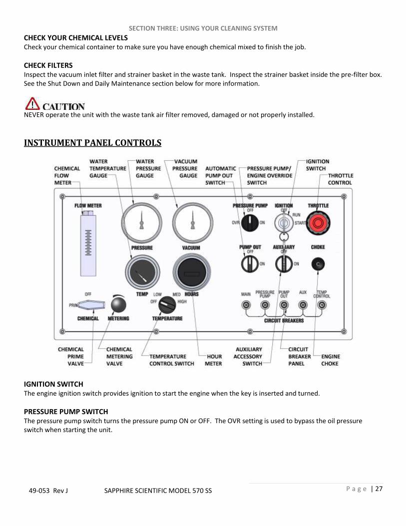
IGNITION SWITCH The engine ignition switch provides ignition to start the engine when the key is inserted and turned.
PRESSURE PUMP SWITCH The pressure pump switch turns the pressure pump ON or OFF. The OVR setting is used to bypass the oil pressure switch when starting the unit.
SECTION THREE: USING YOUR CLEANING SYSTEM
P a g e | 28
49-053 Rev J SAPPHIRE SCIENTIFIC MODEL 570 SS
THROTTLE CONTROL The engine throttle control knob. Turn counter-clockwise to open the throttle (faster speed), clockwise to close the throttle (slower speed). For emergency slow-down, depress the center button and push the throttle control in.
CHOKE CONTROL The engine choke control knob. Pull to open the choke for engine ignition.
PUMP OUT SWITCH The pump out switch is used to turn the pump on or off, if an optional automatic waste pump has been installed.
AUXILIARY SWITCH The auxiliary switch is used to turn an auxiliary item on or off, if an optional accessory item, such as a motorized hose reel, has been installed.
CIRCUIT BREAKERS Circuit breakers for system components, including an automatic waste pump and accessory item, if installed.
TEMPERATURE CONTROL SWITCH The temperature control switch provides multiple pre-set temperature settings of OFF, LOW, MEDIUM and HIGH. The OFF setting allows for continual heat diversion, providing no additional heat to the water through the heat exchanger.
CHEMICAL PRIME VALVE The chemical prime valve allows you to start, stop or prime the chemical flow.
CHEMICAL METERING VALVE The chemical metering valve allows you to control the amount of chemical flow being injected into the cleaning solution. NOTE: For an explanation of gauges, see the section “Gauge Readings and Settings” below.

SECTION THREE: USING YOUR CLEANING SYSTEM
P a g e | 29
49-053 Rev J SAPPHIRE SCIENTIFIC MODEL 570 SS
LOWER FRONT PANEL
CHEMICAL CHECK VALVE The chemical check valve allows the chemical injection into the water stream to form the cleaning solution. This is accessible on the front panel for maintenance and service.
OUTLET FILTER The outlet filter catches debris in the solution stream before it exits the unit for the cleaning tool.
SOLUTION OUTLETS The pressure outlet is where you connect your solution hose. The 570 has 2 outlets for 2 separate solution hoses.
WATER SUPPLY INLET The water supply inlet is where you connect your fresh water supply hose.
VACUUM LUBRICATION CUP The vacuum relief valve lubrication cup is used to deliver lubrication to the vacuum pump. This prevents rust from building up inside the pump. See the shut-down and daily maintenance sections for more information.
VACUUM INLETS The vacuum inlets are where you connect your vacuum hoses. The 570 has one 2 inch and one 2-1/2 inch ports. Always cap unused ports to maintain proper vacuum levels.
SECTION THREE: USING YOUR CLEANING SYSTEM
P a g e | 30
49-053 Rev J SAPPHIRE SCIENTIFIC MODEL 570 SS
STARTING THE UNIT
1. Set throttle control, pull out engine choke, turn pressure pump switch to OVR and turn ignition key to start. 2. Push in engine choke after engine has started. 3. Set throttle control to desired speed. 4. Turn the water pump switch to the ON position.
NOTE: If the unit does not build water pressure after 5 seconds, check for adequate water supply. See “Loss of Water Pump Pressure in the Troubleshooting section of this manual.
VACUUM HOSE Connect the vacuum hose(s) to the vacuum inlet connection at the front of the unit. Connect the opposite end of the vacuum hose(s) the cleaning tool. Let the unit run for a few minutes with the vacuum inlets partially blocked off to warm up the cleaning solution. Sapphire Scientific recommends that the total floor tool size does not exceed #6. Using larger jet sizes on your model 570 SS unit may reduce cleaning temperatures.
PRIMING THE CHEMICAL PUMP NOTE: Sapphire Scientific recommends that the chemical pump be primed whenever the water pump is on. This eliminates possible pressure fluctuations and water pump pulsations related with running the chemical pump dry
1. Insert the chemical prime tube and the chemical inlet tube into the chemical container. NOTE: When inserting the chemical tube into the chemical container, ensure that it stays submerged, as the chemical pump will not function if air is allowed to enter the inlet line.
2. Turn the 3-way chemical selector valve located on the control panel to the PRIME position. The chemical will then flow from the chemical container through the chemical prime tube into the vacuum system.
If the pump does not prime, then: Seal off the vacuum port. The vacuum will quickly draw chemical from the chemical container. After the flow begins, turn the chemical selector valve to OFF position and turn the chemical selector valve back to the PRIME position and continue the procedure.
3. When the chemical flows with no air bubbles, priming has been achieved. Turn the chemical selector valve from PRIME to METER. With the cleaning tool open, check the flow meter and adjust the chemical metering valve until the desired rate of chemical flow is achieved.

SECTION THREE: USING YOUR CLEANING SYSTEM
P a g e | 31
49-053 Rev J SAPPHIRE SCIENTIFIC MODEL 570 SS
AUTOMATIC WASTE PUMP
1. If your unit is equipped with an optional automatic waste pump, connect one end of the 5/8 in. or larger garden hose to the pump-out connection and the other end to an acceptable waste disposal.
2. Turn the pump-out switch located on the front console control panel to the ON position. The waste pump will
now operate automatically throughout the cleaning period. DO NOT use an outlet hose that is smaller than ⅝ in. I.D. NEVER use a waste pump hose as a water inlet hose.
! NEVER dispose of waste water in a storm drain, water way or on ground areas. Always dispose of waste in accordance with Local, State and Federal laws.
OPERATION After you have completed the previous steps, proceed with the cleaning or restoration operation. Place the throttle control cable to a minimum of 50% of throttle control maximum for cleaning or restoration. A float shut-off switch is located inside of the waste tank. It will automatically shut down the unit if the tank reaches its full capacity. If this occurs, empty the waste tank before continuing. When doing flood extraction, the water pump should be in the OFF position. NOTE: Vacuum pressure must have a minimum 7”hg for the diverter valve to work properly. Attaching 1 length of hose should create enough vacuum pressure to achieve this.
CLEANING While cleaning, observe the following guidelines:
Before cleaning, ensure that the wand nozzles are functioning properly. Hold the wand approximately one foot above the surface to be cleaned and open the wand valve. A full even spray should emit from the cleaning nozzles. If the nozzles are not showing a full even spray pattern, adjust, clean, or replace the nozzles, if required.
Usually, chemical solution is applied during the push stroke of the wand during cleaning, and extraction is done on the pull stroke. For heavily soiled carpets, the wand may be used in a scrubbing action, with chemical solution applied in both push and pull strokes, provided that the final stroke is a pull stroke with no chemical injection.

SECTION THREE: USING YOUR CLEANING SYSTEM
P a g e | 32
49-053 Rev J SAPPHIRE SCIENTIFIC MODEL 570 SS
UPHOLSTERY CLEANING Run unit on low speed. Upholstery tools have a lower flow rate and smaller orifices. Switch the temperature control to the desired temperature range. To maintain proper cleaning temperatures, make certain that the unit has been fully heated up prior to cleaning.
STAIR TOOL CLEANING Run unit on low speed. Switch the temperature control to the desired temperature range.
FLOOD RESTORATION/EXTRACTION Set the throttle control on the front control panel to a minimum of 50% of throttle control maximum. Make certain that the water pump switch is in the OFF position Proceed into the extraction process.
DUAL WAND OPERATION The model 570 SS has sufficient capacity for dual wand operation with minimal pressure loss at each wand. The pump pressure and temperature can remain at the same levels as for single wand operation. The chemical flow rate may be set slightly higher than for single wand operation. Always use the LOWEST flow rate that properly cleans the affected areas. Excessive chemicals can cause damage to the items being cleaned.
GAUGE READINGS AND SETTINGS
VACUUM PRESSURE GAUGE With the unit running, the vacuum gauge should read near zero with vacuum hoses disconnected from the vacuum inlets. If the gauge shows a reading, check the filter in the waste tank and the strainer baskets in both the waste tank and pre-filter box for debris. With vacuum ports sealed, and machine running at high speed, the vacuum gauge should read 11 to 13 inches of mercury (in. Hg). This is preset by the factory for the maximum safe operation. Depending on elevation, this may need to be reset at time of installation.
DO NOT exceed 13 in. Hg vacuum pressure. This can cause damage to the vacuum pump.
TEMPERATURE GAUGE The low speed setting is for upholstery and delicate cleaning. Set the machine to medium speed for single wand operation. The high speed setting is for dual wand operation or the use of a powered cleaning tool, such as the Sapphire Scientific HOSS. If a lower temperature is desired, open the temperature control valve on the instrument panel until the desired temperature is obtained. The highest temperatures will be achieved with the valve closed.

SECTION THREE: USING YOUR CLEANING SYSTEM
P a g e | 33
49-053 Rev J SAPPHIRE SCIENTIFIC MODEL 570 SS
WATER PRESSURE GAUGE Water pressure is set by adjusting the pressure regulator valve on the lower front panel for the desired water pressure. Normal settings are as follows:
200 PSI for upholstery cleaning
450 PSI for carpet cleaning
UP TO 1200 PSI maximum If an upholstery tool is designed for truck mount operation, the pressure for upholstery cleaning can be set at the same level as for carpet cleaning.
CHEMICAL FLOW METER The flow meter reads the flow rate from the chemical jug while the chemical is being drawn. The chemical adjustment should normally be set at 1 or 2 GPH for a normal job and at 2 or 3 GPH for an extremely dirty job. NOTE: The setting is also dependent on the type of chemical used and the concentration ratio of chemical to water. Always use the LOWEST flow rate that properly cleans the affected areas. Excessive chemicals can cause damage to the items being cleaned.
HOUR METER The hour meter records the operating time of the machine. This information is used to calculate the water pump and vacuum pump oil change intervals as well as machine maintenance periods.
INCOMING WATER DIVERTER VALVE While the model 570 SS was engineering to deliver maximum water temperature, some jobs may require reduced operating water temperature. The incoming water diverter valve provides lower operating water temperatures by manually diverting a portion of the incoming water supply directly to the water box, where it bypasses the tube and shell heat exchanger. It is not recommended that the valve remain open for normal cleaning operations.

SECTION THREE: USING YOUR CLEANING SYSTEM
P a g e | 34
49-053 Rev J SAPPHIRE SCIENTIFIC MODEL 570 SS
SHUT DOWN AND DAILY MAINTENANCE
1. Flush out the chemical system with fresh water to remove any chemical residue.
2. Remove as much moisture from the vacuum hoses as possible to prevent spillage of wastewater in your vehicle when returning hoses. Disconnect the vacuum hose from the front of the unit.
3. Adjust the throttle cable to the idle position.
4. Switch the temperature control to the lowest setting.
5. Allow the unit to run for at least 5 minutes with the bypass valve open. This will also help to remove any excess
moisture from the vacuum pump and cool the unit down. NOTE: If shutting down for the day: Plug the vacuum inlet on the front of the unit and set the throttle to high. Spray WD-40 (or equivalent) into the blower lubrication cup for 5 seconds. Let machine run 2 minutes to disperse lube to blower.
6. Unplug the vacuum inlet and remove load. Next, return the throttle control cable to idle position, and let idle for 3 to 5 minutes.
7. Turn the ignition switch to the OFF position.
8. Turn the water supply faucet off. Loosen the water supply hose at the water supply to bleed off any pressure.
Unhook the water supply hose and return it to the vehicle.
9. Activate the valves on all cleaning tools. This will relieve any remaining pressure. Disconnect the cleaning tools and solution hoses and return them to the vehicle.
10. Drain the waste tank, disposing of wastewater in a suitable and proper location.
11. Remove the strainer basket from the waste tank. Clean out any debris and re-install. Micro-ban QGC cleaner is
the best product for cleaning and sanitizing the waste tanks as well as other parts of the system
12. Inspect the vacuum inlet filter inside the waste tank daily. Remove and clean the filter if there is any lint or debris present.
NOTE: To remove or install the mesh filter, grip the plastic hexagon section of the filter. Gripping the filter by the screen will collapse or destroy the filter. Grease the threads on the filter when replacing. Hand tighten, then loosen ¼ turn. This will make the filter easier to remove later.
13. At the end of the work day, rinse out the waste tank with fresh water. Microban QGC cleaner as the best product for cleaning and sanitizing the waste tanks as well as other parts of the system
14. Clean the vehicle interior, unit, tools, hoses etc., as needed. Inspect ALL equipment and accessories for any
damage, leaks, wear, etc.
SECTION THREE: USING YOUR CLEANING SYSTEM
P a g e | 35
49-053 Rev J SAPPHIRE SCIENTIFIC MODEL 570 SS
FREEZE PROTECTION
If the unit is exposed to freezing weather conditions, the water inside of the unit may freeze, resulting in SERIOUS DAMAGE to the unit. The following is recommended to prevent this from occurring during the cold weather season: 1. Always park the unit in a heated building when not in use. 2. While out in operation, avoid long periods of shut down as the unit generates heat while running. Keep the unit running just prior to leaving for the next job. 3. If a heated building is not available, winterize the unit with anti-freeze. It is not possible to winterize units that have auxiliary water tanks. If the unit has an auxiliary water tank(s), it must be stored in a heated building.
WINTERIZING THE UNIT WITH ANTIFREEZE
1. Disconnect your water supply. If you have an on-board water supply, fully drain it when your unit is down for long periods.
2. Run the unit on low to extract as much water as possible. This can be done through the bypass valve or an
open-ended hose connected to the solution outlet.
3. Add one gallon of a minimum dilution of 50/50 or 100% glycol based anti-freeze directly to the water box. On pressurized systems, remove the radiator cap to fill.
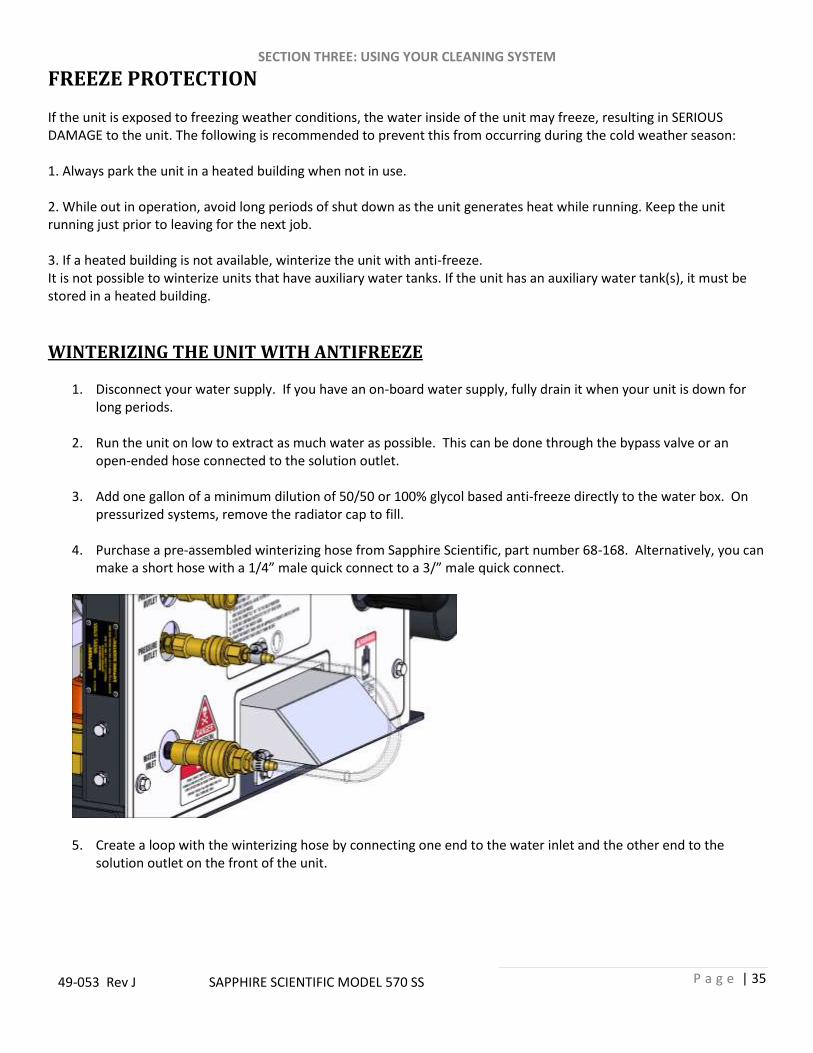
4. Purchase a pre-assembled winterizing hose from Sapphire Scientific, part number 68-168. Alternatively, you can
make a short hose with a 1/4” male quick connect to a 3/” male quick connect.
5. Create a loop with the winterizing hose by connecting one end to the water inlet and the other end to the solution outlet on the front of the unit.
SECTION THREE: USING YOUR CLEANING SYSTEM
P a g e | 36
49-053 Rev J SAPPHIRE SCIENTIFIC MODEL 570 SS
6. Turn the pressure regulator all the way down. Start the unit in idle, turn the water pump switch to the ON position and run coolant through the system. Allow the unit to run for about 3 minutes to fully circulate the anti-freeze.
7. Prime the chemical injection system with a minimum dilution of 50/50 or 100% glycol based antifreeze. Insert
the chemical inlet and prime tube into the anti-freeze container. Turn the chemical valve to PRIME until anti-freeze comes out of the prime hose. Turn the chemical valve to the ON (chemical) position. Ensure that the flow meter indicates flow while the attached tools solution valves are opened. Ensure that all anti-freeze that comes out of the chemical hose goes into an approved container.
8. After 25 seconds, turn the chemical valve to the OFF position.
WINTERIZING THE HOSES AND TOOLS WITH ANTIFREEZE
1. To winterize your hoses and tools, connect all hoses to the solution outlet. Connect a tool to the hoses. Make sure that the tool will drain into an approved anti-freeze container.
2. Make sure the pressure regulator is turned all the way down. Start the unit in idle and turn the water pump on.
Open the tool valve until anti-freeze begins to flow from the tool. Repeat this procedure with all hoses and tools as necessary. Disconnect and store the hoses and tools once they have been filled with anti-freeze.
SECTION THREE: USING YOUR CLEANING SYSTEM
P a g e | 37
49-053 Rev J SAPPHIRE SCIENTIFIC MODEL 570 SS
REMOVING ANTI-FREEZE FROM THE UNIT
1. Connect the solution hoses to the unit, with a tool attached to the opposite end. Start the unit. Turn the water pump on. Open the tool valve and ensure that the anti-freeze goes into an approved container. Allow the anti-freeze to flow into the container until all anti-freeze has been drained.
2. Fill the water box with fresh water and repeat step 1.
3. Connect the water inlet hose to the unit and turn the water supply on. Connect all tools and solution hoses that
were winterized to the solution outlet connection.
4. Open all tool valves and drain the anti-freeze into an approved container until the water runs clear and all of the anti-freeze is purged from the hoses and tools.
5. Insert the chemical prime hose into the approved container. Submerge the chemical hose into fresh water. Turn
the chemical valve to the PRIME position until the water runs clear through the prime hose. Remove the prime hose from the container.
6. Turn the chemical valve to the ON (chemical) position and open attached tools solution valves. This will allow
water to flow to the other side of the system.
7. After all of the anti-freeze has been removed, the unit is ready to operate. The anti-freeze in your approved storage container will eventually become diluted with water. When the anti-freeze level drops below 40% of the total mixture, properly dispose of it and start over with fresh anti-freeze.
!
DO NOT drain used anti-freeze on the ground or into storm drains. Dispose of anti-freeze only in an approved location. Observe Local, State and Federal laws when disposing of anti-freeze.

SECTION FOUR – SERVICE AND MAINTENANCE
P a g e | 38
49-053 Rev J SAPPHIRE SCIENTIFIC MODEL 570 SS
SECTION FOUR: SERVICE AND MAINTENANCE
570 SS MAINTENANCE CHART
DAILY MAINTENANCE Engine Check engine oil level. (2) Fill to proper level.
Vacuum Pump Check vacuum pump oil level. Fill to proper level. Do not overfill. (1)
Vacuum Pump Spray WD-40 (or Equivalent) into the lubrication cup for 10 seconds.
Pressure Pump Check water pump oil level. (3) Fill to proper level.
Vacuum Inlet Filters Inspect filters in the recovery tank, clean and or replace if required. (1) Strainer Basket Empty and clean stainless steel basket in the recovery tank. Vacuum Hoses Rinse with fresh water. Waste Pump-Out (Optional equipment) Inspect and remove any debris or sediment. (1)
WEEKLY MAINTENANCE Float Switch(es) Clean and inspect float switch(es) in the waste tank.
Visual Inspection Check for leaks around the unit, check wires and hoses for wear.
MONTHLY MAINTENANCE
Engine Check air cleaner for damaged, dirty or loose parts.
Engine Inspect drive belts for wear. Replace as needed.
Engine Air Cleaner Check vehicle engine air cleaner. Clean or replace as necessary.
Battery Check fluid level and battery terminals. (1)
Thermal Well Lubricate diverter shaft with anti-seize
Check Valve Strainer Clean and remove debris (1, 4)
Check fasteners Check fastener tightness on all components. Tighten as needed.
QUARTERLY MAINTENANCE Inlet Pressure Regulator Clean and remove any debris. (1, 4)
YEARLY MAINTENANCE Check-Valve Check seat for abnormal wear or debris. Replace as needed.
To maximize the operating life and performance, use only recommended oils, filters and greases. (1) Or as often as required. (2) Change engine oil and oil filter after first 50 hours of operation and then every 200 hours. (3) Change water pump crankcase oil after first 50 hours of operation. (4) Inspect after first week of operation, and remove any debris present. Inspect again after 2 to 4 weeks.

SECTION FOUR – SERVICE AND MAINTENANCE
P a g e | 39
49-053 Rev J SAPPHIRE SCIENTIFIC MODEL 570 SS
570 SS SERVICE INTERVAL CHART SERVICE INTERVALS – EVERY 50 HOURS
High Pressure Hoses Inspect hoses for wear, damage or impending rupture. Replace if damaged.
Engine Change engine oil after first 50 hours of operation.
SERVICE INTERVALS – EVERY 100 HOURS Vacuum Relief Valve Check and adjust vacuum relief valve up to 13” Hg if needed.
Pressure Regulator Lubricate o-rings. Use only o-ring lubricant (Sapphire Scientific P/N 13-003)
Belts Re-tension all belts (1)
Battery Clean battery terminals.
Engine Check spark plugs. Use only OEM spark plugs.
SERVICE INTERVALS – EVERY 200 HOURS Engine Change engine oil and filter.
Engine Check engine air filter
SERVICE INTERVALS – EVERY 250 HOURS Chemical Metering Inspect packing nut on selector and metering valves. Adjust as needed.
SERVICE INTERVALS – EVERY 500 HOURS Pressure Pump Change crankcase oil (2)
Engine Replace in-line fuel filter. (5)
Pulleys and Hubs Check pulleys and hubs for proper torque. (3)
Chemical Pump Change diaphragm and check valves. Inspect disc.
SERVICE INTERVALS – EVERY 1000 HOURS Vacuum Pump Drain, flush and replace oil. (4)
Engine Replace spark plugs. Use only OEM spark plugs.
Engine Replace air filter element. (4)
Engine Valve adjustment .0057 - .0073 in.
SERVICE INTERVALS – EVERY 2000 HOURS Belts Replace all belts.
To maximize the operating life and performance, use only recommended oils, filters and greases. (1) Re-tension belts after first 25 hours, then every 100 hours of operation after. (2) Change water pump crankcase oil after first 50 hours of operation. (3) Check pulley and hub set screws after first 50 hours of operation, and again at 100 hours of operation. (4) Every 1000 hours or yearly, whichever comes first. (5) Every 500 hours or yearly, whichever comes first.

SECTION FOUR – SERVICE AND MAINTENANCE
P a g e | 40
49-053 Rev J SAPPHIRE SCIENTIFIC MODEL 570 SS
MAINTENANCE AND SERVICE ADJUSTMENTS This section of the operator’s manual contains the service and maintenance information for the model 570. A planned preventative maintenance program will ensure that your 570 has optimum performance, long operating life, and a minimum amount of down time.
DO NOT attempt to service this unit while it is running. High speed parts as well as high temperature components may result in severe injury, severed limbs, or fatality. NOTE: Refer to the hour meter as a guide for coordinating a maintenance schedule.

SECTION FOUR – SERVICE AND MAINTENANCE
P a g e | 41
49-053 Rev J SAPPHIRE SCIENTIFIC MODEL 570 SS
ENGINE
Check engine oil daily. Ensure that the proper oil level is maintained. Never overfill.
Change the oil after the first 50 hours of operation. Thereafter, change the oil and filter every 200 hours of operation. Use only OEM oil filters. Use of any other type of oil filter will void engine warranty.
Use high-quality oil of at least API (American Petroleum Institute) service class SG or higher. Do not use additives. High quality 30W oil is recommended. It is never recommended to extend oil change intervals past 200 hours
Engine Oil Capacity 3.4 L 3.59 US qts
Tightening Torque
Drain Plug 33 – 37 N·m 3 kgf·m 24 – 27 lbf·ft
Check the engine air filter every 200 hours, clean as needed. Replace the air filter element every 1000 hours or yearly, whichever comes first.
Replace the inline fuel filter every 500 hours or yearly, whichever comes first.
Check the spark pluge every 500 hours of operation. Replace the spark plugs every 1000 hours. Use only OEM specified spark plugs.
Adjust valves to .0057 - .0073 inches every 1000 hours.
Adjust the engine speed to 3000 RPM max. DO NOT attempt to adjust without a tachometer and NEVER adjust the engine above 3000 RPM NOTE: Additional engine service information can be obtained from the provided Hyundai Operation and Maintenance manual. If service or repair is required, contact an authorized Hyundai Service Center. They will require the serial number of the engine.
NOTE: Using lower service class oil or extending oil change intervals longer than recommended can cause engine damage.

SECTION FOUR – SERVICE AND MAINTENANCE
P a g e | 42
49-053 Rev J SAPPHIRE SCIENTIFIC MODEL 570 SS
VACUUM PUMP NOTE: Refer to the provided Vacuum Pump Operation and Service Manual for specific instructions.
Check the oil level daily on both sides to ensure they are at the proper level. Too little oil will damage and ruin the bearings and gears. Too much oil will result in overheating.
Sapphire Scientific requires that you use only AEON PD-XD Synthetic Blower Lubricant in both sides of the vacuum pump for all operating temperatures. AEON PD-XD is formulated specifically for positive displacement blower service to provide maximum blower protection at any temperature. AEON PD-XD (Sapphire Scientific Part # 13-004) is the only oil that Sapphire Scientific puts in the vacuum pump at the factory. Adding petroleum oil to synthetic oil is NOT recommended.
A lubrication cup has been provided at the front of the console, to prevent rust from building up inside of the vacuum pump. Run the unit for at least 2 minutes to remove any moisture from the vacuum pump. Then, spray WD-40 (or Equivalent) into the lubrication cup for 2 seconds while the unit is running and the vacuum inlet port is sealed. This procedure should be done at the end of every working day.
Drain, flush and replace the oil every 1000 hours or yearly, whichever comes first. NOTE: Two drains are on your vacuum pump. Ensure that both sides of the vacuum pump are filled to their proper level when servicing.

SECTION FOUR – SERVICE AND MAINTENANCE
P a g e | 43
49-053 Rev J SAPPHIRE SCIENTIFIC MODEL 570 SS
PRESSURE PUMP NOTE: Refer to the provided Pressure Pump Operation Manual for specific instructions.
Check the crankcase oil level daily to ensure the proper level. If the level has dropped, check for the source of leakage and repair.
After the first 50 hours of operation, change the crankcase oil Industrial Pump Oil, (Part # 13-030). Change the crankcase oil every 500 hours thereafter.
DRIVE BELTS, PULLEYS and HUBS Check pulley and hub screws after the first 50 hours and again at 100 hours of operation. Re-torque these bolts with a torque wrench. Follow the torque values on the following table. Check pulley set screws and hub screws every 500 hours thereafter. Ensure belts are properly tensioned after checking the torque values. Use Gates EPDM belts. Use a clockwise pattern when re-torqueing screws and continue until the proper torque is achieved.
Torque Values
Engine Lower Front Pulley Bolt 69 lbf·ft
Engine Crankshaft Hub 40 lbf·ft
Engine Fan Mounting Bolts 7 – 8 lbf·ft
Vacuum Pump Hub #38-032 13 lbf·ft
Note: Engine flywheel is factory set at 40 to 43 lbf·ft

SECTION FOUR – SERVICE AND MAINTENANCE
P a g e | 44
49-053 Rev J SAPPHIRE SCIENTIFIC MODEL 570 SS
CHEMICAL PUMP The chemical pump should be rebuilt every 500 hours. This involves changing the diaphragm, check valves, and inspecting the disk. DO NOT attempt to reuse o-rings after the check valves have been removed. Replace all o-rings when servicing check valves.

SECTION FOUR – SERVICE AND MAINTENANCE
P a g e | 45
49-053 Rev J SAPPHIRE SCIENTIFIC MODEL 570 SS
SOLUTION MANIFOLD CHECK VALVE AND STRAINER Unscrew the screen and inspect the strainer after the first week of operation. Remove any debris present. Inspect again after 2 and 4 weeks. Thereafter, inspect the strainer and screen at least monthly. If a frequent build-up of debris is noticed, inspect and clean more frequently. Always inspect the check valve and solution manifold strainer whenever performing service on the chemical pump or if flow problems are occurring in the chemical system.
1. Shut down Unit. 2. Remove and clean strainer mesh. 3. Remove the check valve, ensuring that the small o-
ring on the seat comes out with it. 4. Next, remove the seat using a 5/16 in. Allen wrench. 5. Check the seat for wear or debris. Clean and replace
the seat if necessary. 6. Inspect the poppet and the spring for wear or
damage. Clean and replace as necessary. 7. Re-assemble the check valve. Thread the seat by
hand until snug. Then tighten with a 5/16 in Allen wrench. DO NOT over-tighten.
8. Lubricate the new o-rings with o-ring lubricant (Part # 13-003) and re-install.
NOTE: New o-rings must be installed anytime the check valve is removed. NOTE: Improper seating of the check valve seat, poppet, damaged spring or o-rings will result in poor performance of the chemical system.
23-063 ASSEMBLY, CHECK VALVE MANIFOLD
Item # P/N Qty. Description 1 27-009 1 CAP, CHECK VALVE ASSY. SS 2 41-007 1 ORING, 7/8 ID X 1-1/16 OD 3 15-007 1 SPRING, CHECK VALVE ASSY. 4 27-010 1 POPPET, CHECK VALVE ASSY 5 27-004 1 INSERT, SEAT-CHK VLV ASSY TM 6 27-011 1 SEAT, CHECK VALVE ASSY. 7 41-008 1 ORING, ½ ID 5/8 OD

SECTION FOUR – SERVICE AND MAINTENANCE
P a g e | 46
49-053 Rev J SAPPHIRE SCIENTIFIC MODEL 570 SS
PRESSURE REGULATOR
The pressure regulator holds water pressure at a preset point and bypasses the excess water. To adjust: With the unit running, with the cleaning tool valve closed, the pressure gauge should read 0. With the tool valve open, adjust the pressure by turning the adjusting knob so that the pressure gauge reads between 400 - 1200 PSI.
DO NOT loosen the adjusting body (cap) all the way (counterclockwise) or remove it while the unit is running. Lubricate the o-rings in the pressure regulator every 100 hours. Use only o-ring lubricant (Part #13-003). If you do not, the stem may become seized due to inadequate lubrication. If this occurs:
1. Shutdown the unit. 2. Relieve all pressure from the water system. 3. Remove the cap from the pressure regulator and remove the stem with long nose pliers. 4. Clean and lubricate stem. 5. Reassemble pressure regulator
O-RINGS
VALVE STEM
BODY
KNOB CAP
SPRING
VAVLE NUT
ADJUSTINGKNOB
LOOSEN VAVLE NUT AND REMOVE ENTIRE STEM FROM VALVE BODY TO SERVICE SEALS

SECTION FOUR – SERVICE AND MAINTENANCE
P a g e | 47
49-053 Rev J SAPPHIRE SCIENTIFIC MODEL 570 SS
CHEMICAL METERING SYSTEM Check and inspect the packing nut on the chemical selector and metering valves every 250 hours. Keeping the valve packing’s properly adjusted will prevent leaks and add to the overall life of the valves. When turning the knob, there should be some resistance. If not, slightly tighten the packing nut. DO NOT over tighten. Keeping the packing properly adjusted will eliminate possible leaks and will add to the overall life of the valves.
23-027, CHEMICAL SELECTOR VALVE 23-028, CHEMICAL METERING VALVE
VACUUM INLET FILTER
The vacuum inlet filter in the waste tank should be inspected and cleaned daily.
! When removing the vacuum inlet filter, grip the plastic hexagon section of the filter. Grasping filter by the screen will damage or destroy the filter. Applying anti-seize grease to the threads will allow easier removal of filter when cleaning or replacement is required.
RECOVERY TANK STRAINER BASKET The recovery tank strainer should be emptied and cleaned on a daily basis.

SECTION FOUR – SERVICE AND MAINTENANCE
P a g e | 48
49-053 Rev J SAPPHIRE SCIENTIFIC MODEL 570 SS
BATTERY
! Explosive gases, Dangerous acid! Batteries contain sulfuric acid. To prevent acid burns, avoid contact with skin, eyes and clothing. Batteries also produce explosive hydrogen gases while charging. To prevent fire or explosion, charge batteries only in a well ventilated area. Keep sparks, open flames, as well as any other sources of ignition away from batteries at all times. Remove all jewelry prior to servicing batteries. Before disconnecting the negative (−) ground cable, ensure that all switches are in the OFF position. If ON a spark could occur at the ground connection terminal, which could cause an explosion if hydrogen gas or gasoline vapors are present. ALWAYS disconnect the negative (−) terminal first.
If you do not have a maintenance free sealed battery, check the fluid level in the battery at least once a week. If low, fill to the recommended level ONLY with distilled water. DO NOT overfill the battery. Early failure or poor performance will result due to loss of electrolyte.
Keep cables, terminals and external surfaces of the battery clean and dry. A buildup of corrosive acid or grime on the external surfaces could cause the battery to self-discharge.
Battery terminals should be cleaned every 100 hours to prevent corrosion buildup. Wash the cables, terminals and external surfaces with a mild baking soda and water solution. Rinse thoroughly with fresh water. DO NOT allow baking soda to enter the battery cells, as this will destroy the electrolyte, resulting in battery failure.
VACUUM HOSES To ensure maximum hose life, Sapphire Scientific recommends that you wash out the hoses with fresh water daily. Micro-ban QGC cleaner as the best product for cleaning and sanitizing the wands and hoses as well as other parts of the system.
HIGH PRESSURE SOLUTION HOSES Inspect your high-pressure solution hoses for wear after the first 100 hours. Thereafter, inspect every 50 hours. If the hoses show any signs of damage or impending rupture, replace the hoses.
! NEVER attempt to repair high-pressure solution hoses. Repairing high-pressure solution hoses may result in severe burns and serious injury. All high-pressure solution hoses must be rated for 3000 PSI at 250 deg. F. Thermoplastic hoses do not meet this requirement and should not be used. Severe burns and injury may result if the hoses do not meet these requirements.

SECTION FOUR – SERVICE AND MAINTENANCE
P a g e | 49
49-053 Rev J SAPPHIRE SCIENTIFIC MODEL 570 SS
VACUUM RELIEF VALVE With the unit running at full RPM, block off the airflow at the vacuum inlet port and read the vacuum gauge. If adjustment is required, shut the unit down and adjust the locking nut tension on the vacuum relief valve. Re-start the unit and read the vacuum gauge. Repeat this process until the vacuum relief valve opens at 13” Hg. Always ensure the lock nut is retightened.
WYE STRAINER
Incoming water is filtered through two stainless steel mesh screens. The first screen is located in the wye strainer, located directly behind the water inlet. The wye strainer captures incoming debris and will restrict water flow when clogged. Inspect and clean at least once a month or as needed. Hard water deposits can build and reduce water flow.
INLET PRESSURE REGULATOR
The second stainless steel mesh screen is located inside the inlet pressure regulator. Inspect and clean at least once a month. Hard water deposits can build and reduce water flow. The inlet pressure regulator comes pre-set at the factory.
WYE STRAINER SCREEN

SECTION FOUR – SERVICE AND MAINTENANCE
P a g e | 50
49-053 Rev J SAPPHIRE SCIENTIFIC MODEL 570 SS
VACUUM PUMP BELT REPLACEMENT Belt Replacement Procedures for Model 570: Only use Gates EPDM belts
1. Disconnect the negative battery cable. 2. Remove hose from waste tank to vacuum pump. 3. Remove side hoods and top panel. 4. Remove left and right hand belt guards. 5. Loosen the hose clamp under the blower. 6. Lower the blower plate approximately 1/2 inch. 7. Tip the back of the blower up. 8. Remove all belts. Install new belts. 9. After belts have been installed, check for proper tension and alignment. Do this using a belt gauge. Set
deflection to 1/4”; 10-12 lbs tension. 10. Check pulleys for alignment using a straight edge (example: ½” key stock). Make sure pulley flange touches on 2
places on each pulley (4 total places).
WATER PUMP DRIVE BELT REPLACEMENT To tighten the water pump belt:
1. Loosen the four bolts under the plate, which hold the water pump base to the frame. 2. Adjust the position of the belt tensioning adjusting bolt until the proper belt tension is achieved (1/2” deflection
in the center of the belts, half way between the pulleys). NOTE: Do not over tighten; damage to pump may occur.
3. While checking the alignment, tighten the nuts that hold the water pump to the base.

SECTION FOUR – SERVICE AND MAINTENANCE
P a g e | 51
49-053 Rev J SAPPHIRE SCIENTIFIC MODEL 570 SS
TROUBLESHOOTING
! DO NOT attempt to service this unit while it is running. High-speed parts as well as high temperature components may result in severe injury, severed limbs or fatality. This section of the operator’s manual describes how to look for and repair malfunctions, which may occur. Accurate troubleshooting is based on a thorough and complete understanding of the WATER, CHEMICAL, VACCUM, HEAT TRANSFER, SAFETY and WIRING systems featured in this unit. If there are malfunctions occurring on this unit which you do not understand, refer back to the OPERATION section of this manual and review SYSTEM.
! Do not alter or modify your model 570 SS in any way. Use only replacement parts authorized by Sapphire Scientific. Modifications or use of unapproved parts could create a hazard and will void your warranty. Contact your authorized Sapphire dealer for assistance.

SECTION FOUR – SERVICE AND MAINTENANCE
P a g e | 52
49-053 Rev J SAPPHIRE SCIENTIFIC MODEL 570 SS
ENGINE TROUBLESHOOTING
ENGINE WILL NOT START (STARTER DOES NOT TURN OVER) PROBABLE CAUSE SOLUTION Main circuit breaker on the control panel has been tripped.
After inspecting the unit to determine the cause of the tripped breaker, press the reset button.
Loose or corroded battery connections. Clean, tighten or replace the battery terminals.
Dead battery. Recharge or replace battery
Defective ignition switch. Test ignition switch for power going into the switch. If there is power going in, but none coming out, replace the switch.
Defective starter motor. Test the starter motor. Replace if necessary.
Vacuum pump seized. Refer to the vacuum pump manufacturer service and repair manual.
STARTER TURNS OVER BUT ENGINE WILL NOT START PROBABLE CAUSE SOLUTION Recovery tank is full. Empty the recovery tank.
Defective fuel pump. Replace the fuel pump.
Loose or broken wires leading to the recovery tank float switch.
Repair or replace any broken electrical connections.
Defective float switch inside recovery tank. Check switch for proper operation. Replace if necessary.
Oil pressure switch (located on engine), fuel shut-off solenoid (located on engine).
Test these components. If any are defective, replace. Consult the Kubota Engine Operation and Maintenance Manual.
Engine is malfunctioning. Refer to Kubota Engine Operation and Maintenance Manual.
ENGINE STOPS RUNNING DURING NORMAL OPERATION PROBABLE CAUSE SOLUTION Engine is out of gasoline. Check the fuel tank.
Recovery tank is full. Empty recovery tank.
Main circuit breaker on the control panel has been tripped.
After inspecting the unit to determine the cause of the tripped breaker, press the reset button.
Defective fuel pump. Replace fuel pump.
Defective float switch inside recovery tank. Check switch for proper operation. Replace if necessary.
Oil pressure switch on engine has shut down due to insufficient oil pressure.
Refer to the Kubota Engine Operation and Maintenance Manual. DO NOT restart the engine until the cause is determined and corrected.
No ignition in the engine or the engine is malfunctioning.
Refer to the Kubota Engine Operation and Maintenance Manual.

SECTION FOUR – SERVICE AND MAINTENANCE
P a g e | 53
49-053 Rev J SAPPHIRE SCIENTIFIC MODEL 570 SS
VACUUM PUMP TROUBLESHOOTING
LOSS OF VACUUM (while cleaning, engine RPM is normal but vacuum is lower than expected)
PROBABLE CAUSE SOLUTION Vacuum gauge is giving an improper reading. Examine the tubing between the vacuum relief valve and the
vacuum gauge and remove any blockage.
Vacuum hose(s) is damaged, causing a suction
leak.
Inspect hose(s), repair or replace.
Waste tank gaskets not sealing properly, not
positioned properly.
Inspect the gasket. Repair seal or replace Re-position lid(s).
Plugged vacuum hose or vacuum plumbing
between vacuum inlet and strainer basket.
Unplug vacuum hose or inlet plumbing.
Waste tank filter or strainer basket is plugged. Clean or replace filter. Clean strainer basket.
Loose vacuum pump drive belts. Tighten the drive belts.
Waste tank drain valve is damaged or left open,
causing a vacuum leak.
Drain the waste tank. Close drain valve, if open. Replace valve
if defective.
Vacuum relief valve requires adjustment or has
a vacuum leak due to damaged diaphragm.
Re-adjust the vacuum relief valve. If the vacuum does not
increase, remove and inspect the relief valve diaphragm. If
damaged, replace.
Vacuum exhaust heat exchanger plugged. Remove and clean.
Vacuum pump is worn out. Replace the vacuum pump.
EXCESSIVE VACUUM (while cleaning, engine RPM is normal but vacuum is higher than expected)
PROBABLE CAUSE SOLUTION Vacuum relief valve requires adjustment. Readjust vacuum relief valve to 13” Hg.
Improper throttle adjustment. Adjust throttle to set desired vacuum pressure.

SECTION FOUR – SERVICE AND MAINTENANCE
P a g e | 54
49-053 Rev J SAPPHIRE SCIENTIFIC MODEL 570 SS
PRESSURE PUMP TROUBLESHOOTING
LOSS OF SOLUTION PRESSURE (CLEANING TOOL OPEN, SOLUTION GAUGE READS LOW) PROBABLE CAUSE SOLUTION Water supply is turned off or the float valve is stuck.
Turn the water supply on or up. Check for kinks in the water supply hose. Examine the float or replace.
Solution pump inlet supply line is plugged or drawing air.
Examine the water inlet filter inside the water box. Remove accumulated debris and replace if required. Check for suction leaks and loose clamps or fittings. Tighten any loose fittings or clamps. Replace any ruptured hose(s).
Improper engine speed. Using a tachometer, check the engine speed. Full throttle engine speed is 3000 RPM. Idle engine speed is 1500 RPM.
Pressure regulator o-rings are dry and/or worn.
See instructions on regulator.
Check o-rings. Lubricate and/or replace as needed, using o-ring lubricant.
Pressure regulator is dirty, stuck open, or improperly adjusted. See instructions on regulator.
Clean or repair regulator. Adjust to working pressure. Lubricate o-rings, using o-ring lubricant.
Low pump volume. (Measure the amount of water being returned to the water box from the pressure regulator. It should fill a gallon container about every 17.6 seconds).
Examine the check valves, plunger cups, and cylinder head on the water pump. Repair, whenever required (refer to the water pump service manual).
Defective water pressure gauge. Replace gauge.
Orifice (spray nozzle) in the cleaning tool is worn, defective or wrong size.
Replace Nozzle or change nozzle size.
Debris clogging water lines or water inlet disconnect.
Clean or replace as needed.
Belts loose or broken. Re-tension or replace as needed.
Loss of pump prime. Manually prime water pump.
Temperature Balance Orifice missing. Replace Orifice.
LOSS OF SOLUTION VOLUME AT TOOL (PRESSURE GAUGE READS NORMAL) PROBABLE CAUSE SOLUTION Plugged orifice and/or screen in the cleaning tool.
Unplug or replace orifice and/or screen.
Internal block between the inlet pressure regulator and the solution outlet manifold, or the solution screen is clogged.
Inspect all lines, remove accumulated debris which is blocking flow. Replace any defective hoses. Remove, inspect, and clean the solution screen. De-scale unit and install a water softener, if necessary.
Outlet check valve is plugged. Examine the check valve, remove any debris.
Defective quick-connect on one or more of the high pressure hoses.
Replace defective quick-connects(s) on high pressure hoses(s).
Cleaning tool valve is malfunctioning. Repair or replace valve.
Hose inner lining is constricted. Remove restriction or replace hose.
Air leak in chemical supply line, priming valve or metering valve.
Check for air leaks. Replace faulty parts.

SECTION FOUR – SERVICE AND MAINTENANCE
P a g e | 55
49-053 Rev J SAPPHIRE SCIENTIFIC MODEL 570 SS
PRESSURE PUMP DOES NOT ENGAGE PROBABLE CAUSE SOLUTION Pressure pump circuit breaker has been tripped.
Check the pressure pump circuit breaker on the control panel. Press the circuit breaker reset button.
Defective electrical connection in the console wiring or defective switch.
Examine switch, electrical connections, and wiring. Repair any defective connections. If there is power going to the switch but not going out, replace the defective switch.
Pressure pump has not been activated. Turn pressure pump switch to on.
Defective pressure pump clutch. If there is power in the switch, but not power at the clutch, replace the defective wire. If there is power at the clutch, replace the defective switch.
Loose or broken pressure pump belts. Tighten or replace belts.
CHEMICAL SYSTEM TROUBLESHOOTING
CHEMICAL FLOW METER INDICATES FLOW WITH TOOL VALVE CLOSED PROBABLE CAUSE SOLUTION External leak in chemical piping. Tighten or replace fittings. Re-apply thread sealant where
required.
Outlet check valve is full of debris or damaged, not allowing it to close properly.
Close the chemical valve on the instrument panel. If the flow meter does not indicate flow, remove debris or replace check valve, if necessary.
Chemical pump diaphragm is ruptured. Close the chemical valve on the instrument panel. If the flow meter still indicates flow, replace the chemical pump diaphragm.
Internal leak in chemical valve causing continual flow through prime tube returning to container.
Tighten valve packing nut (see “General Service Adjustments). Replace valve, if necessary.
LOSS OF CHEMICAL (CLEANING TOOL OPEN, NO CHEMICAL) PROBABLE CAUSE SOLUTION Chemical pump is improperly primed. Refer to chemical pump priming instructions.
The strainer at the inlet end of the chemical inlet line is clogged.
Unclog the strainer. If damaged, replace.
Suction leak in the inlet line leading into the chemical pump.
Inspect inlet lines and flow meter for air leaks or damage.
Chemical pump check valve(s) is clogged. Remove any debris from the chemical check valve(s). Replace chemical check valve(s) or seals, if necessary.
Chemical prime/on-off valve or chemical metering valve is defective.
Replace valve(s).
Chemical pump diaphragm is ruptured. Disassemble the chemical pump and replace the damaged diaphragm.
Defective cylinder in the pressure pump. Measure the pump volume. If the pump volume is less than normal, refer to “Loss of Solution Volume” in this section.

SECTION FOUR – SERVICE AND MAINTENANCE
P a g e | 56
49-053 Rev J SAPPHIRE SCIENTIFIC MODEL 570 SS
HEAT EXCHANGER/TEMPERATURE RELATED TROUBLESHOOTING
EXCESSIVE HEATING PROBABLE CAUSE SOLUTION Flow restriction caused by hard water scaling. Descale unit, repair or replace damaged plumbing
components as necessary. Install a water softener.
Not enough water flowing during normal operation.
Check jet size of tool.
Orifice clogged. Clean orifice.
LOSS OF TEMPERATURE PROBABLE CAUSE SOLUTION No vacuum hose is connected. Connect vacuum hose to vacuum inlet port.
Temperature relief valve on water box is stuck open.
Clean temperature relief valve and test. Replace if necessary.
Engine RPM is low. Reset engine RPM.
Defective temperature gauge. Test gauge and sensor. Replace failed component.
Temperature balance orifice missing. Replace orifice.
Manual inlet bypass valve open. Close valve, check for leaks. Replace if leaking.
HEAT EXCHANGER LEAKING
PROBABLE CAUSE SOLUTION Water is dripping from the exhaust port due to condensation build-up.
NOTE: The heat exchanger will produce water condensation discharge at times during normal operation. Do not confuse this with a leak.
Heat exchanger is damaged from frozen water. Inspect heat exchanger for leaks. Visually inspect for damage. Pressure check after removing the unit (maximum test pressure – 1500 PSI).
WASTE PUMP (IF INSTALLED) TROUBLESHOOTING
WASTE PUMP NOT OPERATING NORMALLY PROBABLE CAUSE SOLUTION Defective waste pump float switch. Replace float switch.
Broken diaphragm(s). Replace diaphragm(s).
Weak battery. Charge or replace battery if needed. Check charging station.
Pump-out circuit breaker on control panel has been tripped.
After inspecting waste pump to determine the cause of the tripped circuit breaker, press the reset button.
Inspect check valve for debris or damage. Clean or replace if necessary. Ensure that check valves are seated correctly.

SECTION FIVE: PARTS LISTING AND REFERENCE
P a g e | 57
49-053 Rev J SAPPHIRE SCIENTIFIC MODEL 570 SS
SECTION FIVE: PARTS LISTING AND REFERENCE
CONSOLE ASSEMBLY ................................................................................................ 58 FRAME AND ENCLOSURES ....................................................................................... 62 INSTRUMENT PANEL ................................................................................................ 65 ENGINE ASSEMBLY ................................................................................................... 67 VACUUM PUMP ASSEMBLY ..................................................................................... 71 PRESSURE PUMP ASSEMBLY .................................................................................... 72 CHEMICAL PUMP ..................................................................................................... 74 COOLANT HEAT EXCHANGER ................................................................................... 75 THERMAL WELL ........................................................................................................ 76 RADIATOR AND OVERFLOW BOTTLE ....................................................................... 78 SOLUTION AND BYPASS MANIFOLDS ....................................................................... 79 PRESSURE REGULATOR ............................................................................................ 81 VACUUM INLET BRACKET ......................................................................................... 82 BELT COOLING FAN .................................................................................................. 83 DIVERTER LOCKOUT ................................................................................................. 84 WATER INLET AND BYPASS VALVE ........................................................................... 85 TEMPERATURE CONTROL MODULE ......................................................................... 86 60 GALLON WASTE TANK ......................................................................................... 87 100 GALLON WASTE TANK ....................................................................................... 89 WASTE TANK PORTS KIT ........................................................................................... 91 WASTE TANK HOSES KIT........................................................................................... 92 FUEL PUMP ASSEMBLY ............................................................................................ 93 FUEL FILTER KIT ........................................................................................................ 94 DECALS ..................................................................................................................... 95 WIRING DIAGRAM .................................................................................................... 96 HOSE ROUTING/FLOW DIAGRAM ............................................................................ 97 CHEMICAL FLOW DIAGRAM ..................................................................................... 98 FUEL HOOK-UP KITS ................................................................................................. 99

SECTION FIVE: PARTS LISTING AND REFERENCE
P a g e | 58
49-053 Rev J SAPPHIRE SCIENTIFIC MODEL 570 SS
ILLUSTRATED PARTS LISTING 70-570, CONSOLE, SAPPHIRE 570 SS

SECTION FIVE: PARTS LISTING AND REFERENCE
P a g e | 59
49-053 Rev J SAPPHIRE SCIENTIFIC MODEL 570 SS
70-570, CONSOLE, SAPPHIRE 570 SS

SECTION FIVE: PARTS LISTING AND REFERENCE
P a g e | 60
49-053 Rev J SAPPHIRE SCIENTIFIC MODEL 570 SS
70-570, CONSOLE, SAPPHIRE 570 SS

SECTION FIVE: PARTS LISTING AND REFERENCE
P a g e | 61
49-053 Rev J SAPPHIRE SCIENTIFIC MODEL 570 SS
70-570, CONSOLE, SAPPHIRE 570 SS

SECTION FIVE: PARTS LISTING AND REFERENCE
P a g e | 62
49-053 Rev J SAPPHIRE SCIENTIFIC MODEL 570 SS
69-407, ASSY, FRAME AND ENCLOSURES

SECTION FIVE: PARTS LISTING AND REFERENCE
P a g e | 63
49-053 Rev J SAPPHIRE SCIENTIFIC MODEL 570 SS
69-407, ASSY, FRAME AND ENCLOSURES
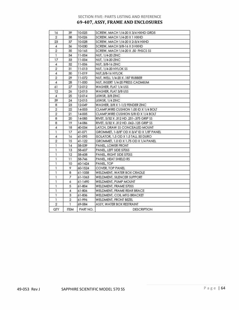
SECTION FIVE: PARTS LISTING AND REFERENCE
P a g e | 64
49-053 Rev J SAPPHIRE SCIENTIFIC MODEL 570 SS
69-407, ASSY, FRAME AND ENCLOSURES

SECTION FIVE: PARTS LISTING AND REFERENCE
P a g e | 65
49-053 Rev J SAPPHIRE SCIENTIFIC MODEL 570 SS
69-277, ASSY, INSTRUMENT PANEL

SECTION FIVE: PARTS LISTING AND REFERENCE
P a g e | 66
49-053 Rev J SAPPHIRE SCIENTIFIC MODEL 570 SS
69-277, ASSY, INSTRUMENT PANEL
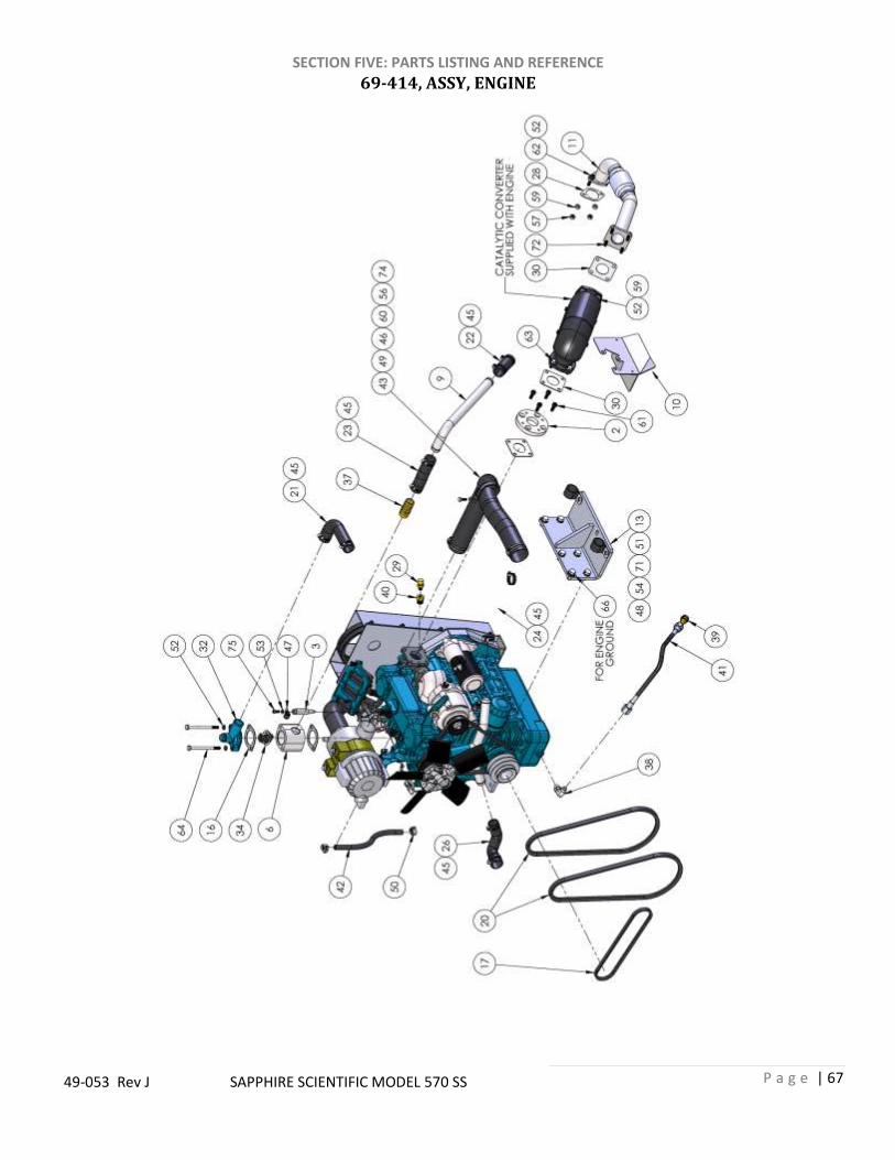
SECTION FIVE: PARTS LISTING AND REFERENCE
P a g e | 67
49-053 Rev J SAPPHIRE SCIENTIFIC MODEL 570 SS
69-414, ASSY, ENGINE

SECTION FIVE: PARTS LISTING AND REFERENCE
P a g e | 68
49-053 Rev J SAPPHIRE SCIENTIFIC MODEL 570 SS
69-414, ASSY, ENGINE

SECTION FIVE: PARTS LISTING AND REFERENCE
P a g e | 69
49-053 Rev J SAPPHIRE SCIENTIFIC MODEL 570 SS
69-414, ASSY, ENGINE

SECTION FIVE: PARTS LISTING AND REFERENCE
P a g e | 70
49-053 Rev J SAPPHIRE SCIENTIFIC MODEL 570 SS
69-414, ASSY, ENGINE

SECTION FIVE: PARTS LISTING AND REFERENCE
P a g e | 71
49-053 Rev J SAPPHIRE SCIENTIFIC MODEL 570 SS
69-411, ASSY, VACUUM PUMP

SECTION FIVE: PARTS LISTING AND REFERENCE
P a g e | 72
49-053 Rev J SAPPHIRE SCIENTIFIC MODEL 570 SS
69-465, ASSY, PRESSURE PUMP

SECTION FIVE: PARTS LISTING AND REFERENCE
P a g e | 73
49-053 Rev J SAPPHIRE SCIENTIFIC MODEL 570 SS
68-180, PRESSURE PUMP BREAKDOWN
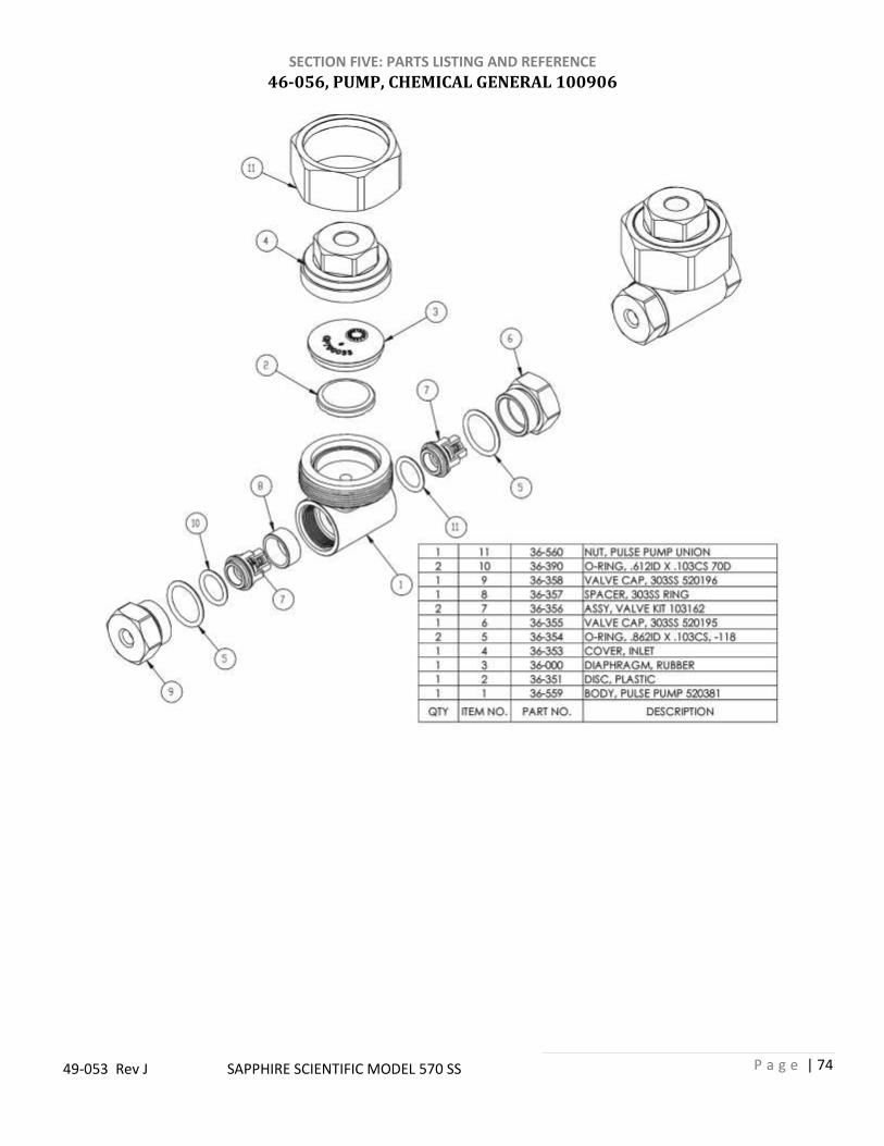
SECTION FIVE: PARTS LISTING AND REFERENCE
P a g e | 74
49-053 Rev J SAPPHIRE SCIENTIFIC MODEL 570 SS
46-056, PUMP, CHEMICAL GENERAL 100906

SECTION FIVE: PARTS LISTING AND REFERENCE
P a g e | 75
49-053 Rev J SAPPHIRE SCIENTIFIC MODEL 570 SS
69-863, ASSY, COOLANT HEAT EXCHANGER

SECTION FIVE: PARTS LISTING AND REFERENCE
P a g e | 76
49-053 Rev J SAPPHIRE SCIENTIFIC MODEL 570 SS
69-583, ASSY, THERMAL WELL

SECTION FIVE: PARTS LISTING AND REFERENCE
P a g e | 77
49-053 Rev J SAPPHIRE SCIENTIFIC MODEL 570 SS
69-583, ASSY, THERMAL WELL

SECTION FIVE: PARTS LISTING AND REFERENCE
P a g e | 78
49-053 Rev J SAPPHIRE SCIENTIFIC MODEL 570 SS
69-412, ASSY, RADIATOR AND OVERFLOW BOTTLE

SECTION FIVE: PARTS LISTING AND REFERENCE
P a g e | 79
49-053 Rev J SAPPHIRE SCIENTIFIC MODEL 570 SS
69-249, ASSY, SOLUTION AND BYPASS MANIFOLDS

SECTION FIVE: PARTS LISTING AND REFERENCE
P a g e | 80
49-053 Rev J SAPPHIRE SCIENTIFIC MODEL 570 SS
69-249, ASSY, SOLUTION AND BYPASS MANIFOLDS

SECTION FIVE: PARTS LISTING AND REFERENCE
P a g e | 81
49-053 Rev J SAPPHIRE SCIENTIFIC MODEL 570 SS
69-506, ASSY, PRESSURE REGULATOR
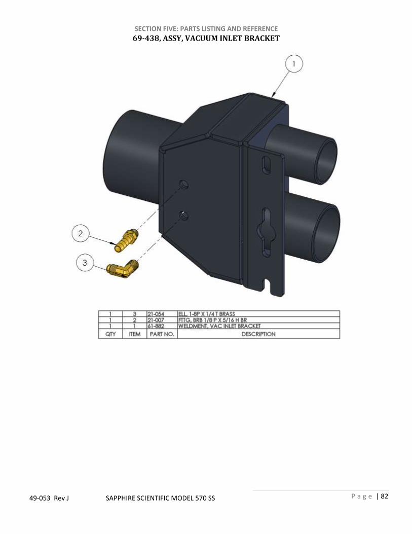
SECTION FIVE: PARTS LISTING AND REFERENCE
P a g e | 82
49-053 Rev J SAPPHIRE SCIENTIFIC MODEL 570 SS
69-438, ASSY, VACUUM INLET BRACKET

SECTION FIVE: PARTS LISTING AND REFERENCE
P a g e | 83
49-053 Rev J SAPPHIRE SCIENTIFIC MODEL 570 SS
69-208, ASSY, BELT COOLING FAN

SECTION FIVE: PARTS LISTING AND REFERENCE
P a g e | 84
49-053 Rev J SAPPHIRE SCIENTIFIC MODEL 570 SS
69-525, ASSY, DIVERTER LOCKOUT

SECTION FIVE: PARTS LISTING AND REFERENCE
P a g e | 85
49-053 Rev J SAPPHIRE SCIENTIFIC MODEL 570 SS
69-423, ASSY, WATER INLET AND BYPASS VALVE

SECTION FIVE: PARTS LISTING AND REFERENCE
P a g e | 86
49-053 Rev J SAPPHIRE SCIENTIFIC MODEL 570 SS
69-634, ASSY, TEMPERATURE CONTROL MODULE

SECTION FIVE: PARTS LISTING AND REFERENCE
P a g e | 87
49-053 Rev J SAPPHIRE SCIENTIFIC MODEL 570 SS
69-926 60 GALLON WASTE TANK ASSEMBLY

SECTION FIVE: PARTS LISTING AND REFERENCE
P a g e | 88
49-053 Rev J SAPPHIRE SCIENTIFIC MODEL 570 SS
69-926 60 GALLON WASTE TANK ASSEMBLY TABLE

SECTION FIVE: PARTS LISTING AND REFERENCE
P a g e | 89
49-053 Rev J SAPPHIRE SCIENTIFIC MODEL 570 SS
69-925 100 GALLON WASTE TANK ASSEMBLY
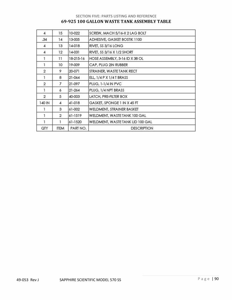
SECTION FIVE: PARTS LISTING AND REFERENCE
P a g e | 90
49-053 Rev J SAPPHIRE SCIENTIFIC MODEL 570 SS
69-925 100 GALLON WASTE TANK ASSEMBLY TABLE

SECTION FIVE: PARTS LISTING AND REFERENCE
P a g e | 91
49-053 Rev J SAPPHIRE SCIENTIFIC MODEL 570 SS
48-142 WASTE TANK PORTS KIT

SECTION FIVE: PARTS LISTING AND REFERENCE
P a g e | 92
49-053 Rev J SAPPHIRE SCIENTIFIC MODEL 570 SS
48-134 WASTE TANK HOSES KIT

SECTION FIVE: PARTS LISTING AND REFERENCE
P a g e | 93
49-053 Rev J SAPPHIRE SCIENTIFIC MODEL 570 SS
68-030 FUEL PUMP AND HOUSING ASSEMBLY
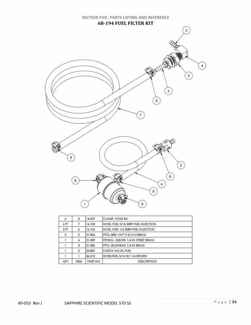
SECTION FIVE: PARTS LISTING AND REFERENCE
P a g e | 94
49-053 Rev J SAPPHIRE SCIENTIFIC MODEL 570 SS
68-194 FUEL FILTER KIT

SECTION FIVE: PARTS LISTING AND REFERENCE
P a g e | 95
49-053 Rev J SAPPHIRE SCIENTIFIC MODEL 570 SS
DECALS
44-084, DECAL, CAUTION HOT SURFACE
44-080, DECAL, WARNING USE IN WELL VENTILATED AREA
44-085, DECAL, WARNING ROTATING
MACHINERY
44-066, DECAL, WARNING ELECTRIC
SHOCK
44-067, DECAL, WARNING READ MANUAL
44-090, DECAL, WARNING MANIFOLD
MAINTENANCE
44-079, DECAL, UNLEADED FUEL ONLY
44-087 DECAL, PRODUCT 570 SS

SECTION FIVE: PARTS LISTING AND REFERENCE
P a g e | 96
49-053 Rev J SAPPHIRE SCIENTIFIC MODEL 570 SS
WIRING DIAGRAM

SECTION FIVE: PARTS LISTING AND REFERENCE
P a g e | 97
49-053 Rev J SAPPHIRE SCIENTIFIC MODEL 570 SS
HOSE ROUTING AND FLOW DIAGRAM

SECTION FIVE: PARTS LISTING AND REFERENCE
P a g e | 98
49-053 Rev J SAPPHIRE SCIENTIFIC MODEL 570 SS
CHEMICAL FLOW DIAGRAM

SECTION FIVE: PARTS LISTING AND REFERENCE
P a g e | 99
49-053 Rev J SAPPHIRE SCIENTIFIC MODEL 570 SS
FUEL HOOK-UP KITS 1992 TO 2002 FORD FUEL LINE INSTALLATION
69-005FI KIT, FUEL HOOKUP FORD FI Item No. Part Number Qty Description
1 66-031 1 ADAPTOR,VENT TUBE(FORD)
2 21-086 2 FTTG, BULKHEAD 1/4 IN BRASS
3 21-039 2 ELL,1/4 IN LG STREET BRASS
4 21-038 1 ELL, STREET 1/8 IN BRASS
5 21-007 2 FTTG, BRB 1/8P X 5/16 H BR
6 21-006 4 FTTG, BRB 1/4P X 5//16H BR
7 18-028 1 HOSE, 3/16 X 25 (1/8P X 1/8P NO COVER)
8 14-011 6 CLAMP, HOSE FUEL # 6
9 14-000 2 CLAMP, HOSE #12
Cut Existing Hose 3” From Hose End Vent Tube
Fuel Suction
Line
Fuel Return
Line
To Bottom of
Tank
1 9
7
5
4
8

SECTION FIVE: PARTS LISTING AND REFERENCE
P a g e | 100
49-053 Rev J SAPPHIRE SCIENTIFIC MODEL 570 SS
CHEVY AND GMC FULL SIZE VAN FUEL LINE INSTALLATION
69-003FI KIT, FUEL HOOKUP 97 & 2002 FI Item No. Part Number Qty Description
1 14-010 2 CLAMP, HOSE # 32
2 14-011 6 CLAMP, HOSE FUEL # 6
3 21-006 4 FTTG, BRB 1/4P X 5//16H BR
4 21-007 2 FTTG, BRB 1/8P X 5/16 H BR
5 21-038 1 ELL, STREET 1/8 IN BRASS
6 21-039 2 ELL,1/4 IN LG STREET BRASS
7 21-086 2 FTTG, BULKHEAD 1/4 IN BRASS
8 21-116 1 ELL, 1/8 FP X 1/8 FP BRONZE
9 66-030 1 ADAPTOR,FUEL NECK(CHEVY)
10 18-027 2 HOSE, 3/16 X 5 (1/8P X 1/8P NO CVR)
2 1
9
4
1
8
Remove Existing
Hose and Cut in
Half
CAUTION: Do Not Cut Inner Hose
To Bottom of
Tank
Fuel Return
Line
Fuel Suction
Line

SECTION FIVE: PARTS LISTING AND REFERENCE
P a g e | 101
49-053 Rev J SAPPHIRE SCIENTIFIC MODEL 570 SS
2003 CHEVY AND GMC FULL SIZE VAN FUEL LINE INSTALLATION
69-018FI KIT, FUEL HOOKUP 2003 CHEVY FI Item No. Part Number Qty Description
1 66-034 1 ADAPTOR, FUEL FLR CHVY 2003
2 14-006 2 CLAMP, HOSE # 20
3 18-028 1 HOSE, 3/16 X 25 (1/8P X 1/8P NO COVER)
4 14-011 6 CLAMP, HOSE FUEL # 6
5 21-038 1 ELL, STREET 1/8 IN BRASS
6 21-007 2 FTTG, BRB 1/8P X 5/16 H BR
7 21-039 2 ELL,1/4 IN LG STREET BRASS
8 21-006 4 FTTG, BRB 1/4P X 5//16H BR
9 21-086 2 FTTG, BULKHEAD 1/4 IN BRASS
2
3
4
5
6
1
Trim Fuel Filler Neck 1”. Reinstall Flapper Valve Inside of Fuel Filler Hose
Cut Hose and Remove Flapper Valve

SECTION FIVE: PARTS LISTING AND REFERENCE
P a g e | 102
49-053 Rev J SAPPHIRE SCIENTIFIC MODEL 570 SS
1997-2002 DODGE FULL SIZE VAN FUEL LINE INSTALLATION
69-004FI KIT, FUEL HOOKUP CHEVY/DODGE FI Item No. Part Number Qty Description
1 14-010 2 CLAMP, HOSE # 32
2 66-030 1 ADAPTOR,FUEL NECK(CHEVY)
3 21-038 1 ELL, STREET 1/8 IN BRASS
4 14-011 6 CLAMP, HOSE FUEL # 6
5 21-007 2 FTTG, BRB 1/8P X 5/16 H BR
6 18-028 1 HOSE, 3/16 X 25 (1/8P X 1/8P NO COVER)
7 21-086 2 FTTG, BULKHEAD 1/4 IN BRASS
8 21-006 4 FTTG, BRB 1/4P X 5//16H BR
9 21-039 2 ELL,1/4 IN LG STREET BRASS
Fuel Suction
Line
Remove Existing Hose and Cut in Half
CAUTION: Do Not Remove Ball
To Bottom of
Tank
Fuel Return
Line
1
2
3
4
5