Embed Size (px)
Citation preview

5/16 Rev G 57-02399

5/16 Rev G 57-02399 1

5/16 Rev G 57-02399 2
TABLE OF CONTENTS
INTRODUCTION�������������.�������������������������������3
STORE CONDITIONS / LOCATION ����.������.�..��������������.��.���.....��..3
WARNING LABELS AND SAFETY INSTRUCTIONS���..�..�������������������...���.4
PRE-INSTALLATION INSTRUCTIONS���������..�..����������.....................�..�..���..4
Inspection for Shipping Damage . .. ......4
INSTALLATION INSTRUCTIONS���������������������������������..�.�..5
General Instructions . .. ... .5
Thermometer Installation . .. 5
Shelf and Shelf Lightin Installation .. 5-10
Plumbing .. 11
ELECTRICAL��..���������������������������..��������.��..����12
STARTING PROCEDURE�����������������������������������..����12
FINAL CHECK LIST�������������������������������.������..��........12
LOADING����������������������������������������...�..����.13
PLACING PRODUCT IN CABINET ����������������������������...�.�.���...13
CLEANING����������������������������������������..����..�13
ELECTRONIC TEMPERATURE CONTROL �������������������������.������14
Fan .. .. ... 14
Defrost . . ...14
Manual Defrost ... .. 14
Alarm Signals��������������������������������.����...����14
Setpoint.����������������������������������..�����.....��..15
How to change parameters����������������������������..���...��..15
List Of Parameters�����������������������������.....��..�����...15
ELECTRICAL CONNECTIONS�����������������������������..�������...15
PROBE CONNECTIONS���������������������������������..�..��.��..15
SENSOR PROBE TEMPERATURE AND RESISTANCE������������������..����.��.....16
SERVICE INSTRUCTIONS (Trouble Shooting Guide)������������������..�����.��...17
PART NUMBERS�������������������������...������.���.......................18-21
ACCESSORIES LIST��������������������������...�����.�����.����.22
SALE AND DISPOSAL��������.�����������������...�����.�����.����.23
WIRING DIAGRAMS���������������������������.���.�����...�.��...24-29

5/16 Rev G 57-02399 3
INTRODUCTION
Thank you for purchasing a Master-Bilt®
cabinet. This manual contains important instructions for installing, using and
servicing a Master-Bilt®
Open Air Merchandiser, OAM, series open air case. Read all these documents carefully
before installing or servicing your equipment. This manual should be left in the care of the store owner or manager.
STORE CONDITIONS / LOCATION
The Master-Bilt®
OAM cases are designed to operate in the controlled environment of an air conditioned store. The
store temperature should be at or below 75°F and a relative humidity of 55% or less. At higher temperature or humidity conditions, the performance of these cases may be affected and the capacity diminished. It is not uncommon in a newly constructed store for the temperature and humidity to be above design conditions. These excessive conditions may produce sweating in the case until the store is operational and the ambient environment is more desirable.
The Master-Bilt®
OAM should not be positioned where it is directly exposed to rays of the sun or near a direct source
of radiant heat or air flow. No HVAC return or supply air ducts may be located near case openings. This will adversely affect the case air flow and will result in poor performance. Do not open windows or doors that will affect the case air flow. The maximum air velocity near the case air return is 50 FPM. If this case is to be located against a wall there should be at least a 6” space between the wall and the back of the case. The cabinet also requires a clearance of 10” at the top. This space will allow for the circulation of air behind the case.
These cases should always be loaded properly. This unit will operate differently when loaded or unloaded. Consult the section of this manual that specifies loading procedures. A pipe loop acts as a trap is included with each case. It is important that each case has this installed. Consult the section of this manual for installing and piping the drain.
NOTICE
Read this manual before installing your cabinet. Keep the manual and refer to it before
doing any service on the equipment. Failure to do so could result in personal injury or damage to the cabinet.
DANGER
Improper or faulty hook-up of electrical components of the refrigeration units can result in
severe injury or death.
NEVER use an extension cord to power these units. All electrical wiring hook-ups must be done in
accordance with all applicable local, regional or national standards.
NOTICE
Installation and service of the refrigeration and electrical components of the cabinet must be performed by a
refrigeration mechanic and/or a licensed electrician. The portion of this manual covering refrigeration and electrical components contain technical instructions intended only for persons qualified to perform refrigeration and electrical work. This manual cannot cover every installation, use or service situation. If you need additional information, call or write us: Customer Service Department Master-Bilt Products Highway 15 North New Albany, MS 38652 Phone (800) 684-8988 Fax (800) 684-8988

5/16 Rev G 57-02399 4
CAUTION!
GROUND REQUIRED
FOR SAFE OPERATION
WARNING LABELS AND SAFETY INSTRUCTIONS
This symbol is the safety-alert symbol. When you see this symbol on your cabinet or in this manual, be alert to the potential for personal injury or damage to your equipment. Be sure you understand all safety messages and always follow recommended precautions
and safe operating practices.
NOTICE TO EMPLOYERS
You must make sure that everyone who installs, uses or services your cabinet is thoroughly familiar with all
safety information and procedures. Important safety information is presented in this section and throughout this section and throughout the manual. The following signal words are used in the warnings and safety messages:
DANGER: Severe injury or death will occur if you ignore the message.
WARNING: Severe injury or death can occur if you ignore the message.
CAUTION: Minor injury or damage to your cabinet can occur if you ignore the message.
NOTICE: This is important installation, operation or service information. If you ignore the message, you may damage your cabinet.
The warning and safety labels shown throughout this manual are placed on your Master-Bilt Products cabinet
at the factory. Follow all warning label instructions. If any warning or safety labels become lost or damaged,
call your customer service department at (662) 534-9061 for replacements.
This label is located on the electrical control This label is attached to the cabinet power cord on
box and on the rear access cover. models with a power cord.
PRE-INSTALLATION INSTRUCTIONS
INSPECTION FOR SHIPPING DAMAGE You are responsible for filing all freight claims with the delivering truck line. Inspect all cartons and crates for damage as soon as they arrive. If damage is noted to shipping crates or cartons or if a shortage is found, note this on the bill of lading (all copies) prior to signing. If damage is discovered when the cabinet is uncrated, immediately call the delivering truck line and follow up the call with a written report indicating concealed damage to your shipment. Ask for an immediate inspection of your concealed damage item. Crating material must be retained to show the inspector from the truck line.

5/16 Rev G 57-02399 5
INSTALLATION INSTRUCTIONS
GENERAL INSTRUCTIONS
1. Be sure the equipment is properly installed by competent service people. 2. Keep the equipment clean and sanitary so it will meet your local sanitation codes. Wipe up all spills, clean with
water and a mild detergent, then rinse with clean water. A reservoir is provided to contain inner spills. Peridocially inspect reservoir and clean as needed.
3. Rotate your stock so that older stock does not accumulate. A "First-In, First-Out" rotation practice will keep the
products in good salable condition. 4. Product should not be put in the case for at least 2 hours after it is started. 5. Stock cases as quickly as possible, exposing only small quantities to store temperatures for short periods of
time. 6. When replacing burned LED light bars, be sure that the electrical power to the lighting circuit is turned off.
To comply with Sanitation requirements, this cabinet must be mounted on casters, legs (6” high min.) or the base must be sealed to the floor with NSF listed silicone sealant. Minimum clearance as follows: 10” air space at top, 6” at the rear, and 0” air space at each side required for compliance.
THERMOMETER INSTALLATION
Install provided thermometer at the clip on the price tag moulding near the top left edge of the case. Remove the tape backing and press the thermometer in place.
SHELF INSTALLATION
SHELF SHELF BRACKET
SHELF BRACKET
SHELF BRACE

5/16 Rev G 57-02399 6
Shelf Assembly Items
1) If this is a lighted shelf assembly, position shelf brace and cable as shown in the image below. If this is not a
lighted shelf assembly, skip this step and proceed to the next step.
2) With shelf top turned upside down, position shelf brace midway inside shelf top and position the shelf
brace so the electrical outlet hole is to the left side of the shelf top.
OR

5/16 Rev G 57-02399 7
3) Position a shelf bracket with its sides flush with the inside of shelf top and angled as shown in the image
below. To fully secure the shelf bracket, the installer needs to pry the angle of the shelf top ,indicated by
arrow in the image, so the bracket will snap under shelf top while also manuevering the shelf brace so it fits
in the notch of the shelf bracket as the shelf bracket is being lowered into the shelf top. Perform for both
sides of the shelf assembly.
The completed assembly should look similar to the images below.
ELECTRICAL OUTLET
HOLE
SHELF BRACKET
NOTCH

5/16 Rev G 57-02399 8
Upside down view of completed shelf assembly
Upright isometric view of shelf assembly
4) If this is the shelf lighting assembly ,mount lighting assembly in desired location on shelf using magnetic
brackets and pull cable as needed to decrease slack in cable.

5/16 Rev G 57-02399 9
5) The shelves can be positioned to stock products horizontally or at an angle. To position the shelves
horizontally, use the notches indicated on the shelf bracket at the desired level using the spaces available on
the pilasters. Make sure the corresponding pilaster slots are used on both sides to make sure shelves are
level.
Use the outside notches on shelf bracket to position the shelf assemblies horizontally
6) To position the shelves at a slight angle, use the notches indicated on the shelf bracket at the desired level
using the spaces available on the pilasters. Make sure the corresponding pilaster slots are used on both
sides to make sure shelves are level.

5/16 Rev G 57-02399 10
Use the inside notches on shelf bracket to position shelf assemblies at an angle
7) If this is a lighted shelf assembly, plug cable into the nearest outlet located on back panel.

5/16 Rev G 57-02399 11
PLUMBING Each OAM case has an optional electric, heated condensate pan and a looped drain hose connecting the drain to the outside of the case. It is very important that this loop not be removed as it will result in diminished peformance of the case without it. End user should plumb drain hose to floor drain. Please observe the following:
1. Always install drains in accordance with local codes. 2. Use largest possible size pipe for drains, ½” ID minimum is recommended. 3. Provide as much downhill slope as possible. 4. Prevent drains from freezing. Do not install drains in contact with uninsulated suction lines.
If it is preferred to use the heated condensate pan:
1. Remove rear guard from refrigeration area. 2. Remove drain hose from loop inside condensate pan (DO NOT REMOVE LOOP) and discard 3. Remove condensate power cord from refrigeration area, and route thru bushing where drain hose was. 4. Re-install rear guard, connect condensate vaporizer cord to dedicated 115v outlet.
NOTICE TO STORE OWNERS / MANAGERS
Moisture or liquid around or under the cabinet is a potential slip/fall hazard for persons walking by or working
in the general area of the cabinet. Any cabinet malfunction or housekeeping problem that creates a slip/fall
hazard around or under the cabinet should be corrected immediately.
- If moisture or liquid is observed around or under a Master-Bilt® cabinet, an immediate investigation should be
made by qualified personnel to determine the source of the moisture or liquid. The investigation made should determine if the cabinet is malfunctioning or if there is a drain pipe leaking.

5/16 Rev G 57-02399 12
ELECTRICAL
WARNING
Before servicing electrical components in the case make sure all power to case is off. Always use a qualified
technician.
STARTING PROCEDURE
1. Start compressor and allow the case to pull down to 42 degrees or below before placing product into the OAM. 2. Check that the compressor cycles off and back on at least once.
FINAL CHECK LIST
A. Check that the evaporator drain line is properly connected. B. All shelves are properly installed.
C. All LED light bars are properly secure to the bottom of the shelf and plug to the cabinet’s back wall.
D. Check electrical supply voltage to make sure it is in range.
E. All loose items and debris is removed from inside of unit and lower equipement compartment.
F. Check condensing unit for vibrating or rubbing tubing. Dampen and clamp as required.
G. Check that the temperature inside of the case is between 35 and 42 degrees.

5/16 Rev G 57-02399 13
LOADING
Product should be at or below operating temperature before being placed in cabinet. Stock cases as quickly as possible, exposing only small quantities to store temperatures for short periods of time. It is important to keep stock rotated properly so that older stock does not accumulate. A “First-In, First-Out” rotation practice will keep the products in good salable condition. Avoid loading the case so that product sticks out beyond the shelves or blocking the return air grille at the bottom of the case. This will interfere with the air flow of the case and will result in diminished performance.
PLACING PRODUCT IN THE CABINET Do not load the cabinet with product to the point that the air discharge grille, air intake grille, or the air curtain created by the discharge air, is blocked. The following diagrams shows proper loading for a Vertical & Horizontal Open Air Merchandiser, VOAM & HOAM.
Vertical Open Air Merchandiser (VOAM) Horizontal Open Air Merchandiser (HOAM)
CLEANING
To avoid electrical shock, turn the power off before cleaning.
The OAM cabinets are designed so that spills will accumulate in a drain pan. The drain pan is located underneath the return air grille/air intake grille. Be sure to clean all areas with a mild detergent and water periodically. The side panels contains slots/grooves that needs to be cleaned periodally with soft soap mixture and small brush or damp cloth. Do not use harsh chemicals as it may cause discoloration. Some OAM cabinets consist of side end panels with vertical and horizontal slots. These slots needs to be cleaned periodically with a mild detergent, water, and a tube bush that can effectively clean area of any containments or debris that may accumulate during the operation of the cabinet.

5/16 Rev G 57-02399 14
MASTER-BILT® ELECTRONIC REFRIGERATION CONTROL
Display Lay-out
Compressor When power is first turned on to the control, the LED indicator under COMP on the display starts blinking. After one-minute delay the compressor comes on. The LED indicator stays on while compressor relay is energized. Display will show actual box temperature. Picture above is the display layout. The compressor will be cycled off when the actual box temperature reaches its set point. The COMP indicator will be off.
Fan The fans will run constantly during cool mode and defrost mode. When the evaporator temp is above 55oF the
FAN will be off.
Defrost The control uses time defrost with 6 defrost per day. The defrost scheme can be re-set for special applications. During defrost the display will show DEF and the defrost LED indicator on. The control begins timing the defrost when power is turned on. Four defrost per day means it will occur every 4 hours.
MANUAL DEFROST
Defrosting may also be induced manually by keeping the defrost button pressed for 3 seconds. Once defrost has started, cabinet will go through defrost and drip time pull down cycle.

5/16 Rev G 57-02399 15
HOW TO CHANGE THE SETPOINT
HOW TO CHANGE a parameter value
LIST OF PARAMETERS
Here is a list of the parameters the value of which can be changed in the programming mode, as well as their ranges.
Display
Symbol Parameter
Range
Master-Bilt®
Setting
SP Temperature Set Point SPL SPH 30°F
HYS Temperature Differential 1 to 255°F 5°
SPL Minimum Temperature limit setpoint -50 SPH 25°F
SPH Maximum Temperature limit setpoint SPH 120° 40°F
AHA High Temperature alarm -50 120° 65°F
ALA Low Temperature Alarm 50 120° 0°F
ATD Temperature Alarm Delay 0 120min 30min
DFR Number of Defrost Cycle per 24hr 0 24 6/day
DLI Defrost Termination Temperature -50 120° 40°F
DTO Maximum Defrost Duration 1 120min 10 min
ELECTRICAL CONNECTIONS
The controller is provided with screw/push terminal block to connect cables with a cross section up to 2,5 mm2. Before
connecting cables make sure the power supply complies with the control’s requirements. Separate the probe cables from the power supply cables, from the outputs and the power connections. Do not exceed the maximum current allowed on each relay, in case of heavier loads use a suitable external relay or contactor’s.
PROBE CONNECTIONS
The probes shall be mounted with the bulb upwards to prevent damages due to casual liquid infiltration. It is recommended to place the thermostat probe away from air streams to correctly measure the average room temperature. Place the defrost termination probe among the evaporator fins in the coldest place, where most ice is formed, far from heaters or from the warmest place during defrost, to prevent premature defrost termination.

5/16 Rev G 57-02399 16
SENSOR PROBE TEMPERATURE AND RESISTANCE
NTC10K Temperature-Resistance
Temp (ºC) Temp (ºF) R-low (Kohm) R-center (Kohm) R-high (Kohm)
-40 -40 188.021 195.652 203.573
-35 -31 142.788 148.171 153.741
-30 -22 109.522 113.347 117.294
-25 -13 84.823 87.559 90.374
-20 -4 66.270 68.237 70.255
-15 5 52.229 53.650 55.104
-10 14 41.477 42.506 43.557
-5 23 33.147 33.892 34.651
0 32 26.678 27.219 27.767
5 41 21.630 22.021 22.417
10 50 17.643 17.926 18.210
15 59 14.472 14.674 14.877
20 68 11.938 12.081 12.224
25 77 9.900 10.000 10.100
30 86 8.217 8.315 8.413
35 95 6.854 6.948 7.043
40 104 5.745 5.834 5.923
45 113 4.834 4.917 5.001
50 122 4.084 4.161 4.239
55 131 3.464 3.535 3.607
60 140 2.949 3.014 3.081
65 149 2.526 2.586 2.647
70 158 2.173 2.228 2.283
75 167 1.875 1.925 1.976
80 176 1.623 1.669 1.715
85 185 1.411 1.452 1.495
90 194 1.230 1.268 1.307
95 203 1.075 1.110 1.145
100 212 0.942 0.974 1.006
105 221 0.829 0.858 0.888
110 230 0.732 0.758 0.785
115 239 0.647 0.671 0.696
120 248 0.574 0.596 0.619
125 257 0.511 0.531 0.552
5/16 Rev G 57-02399 17
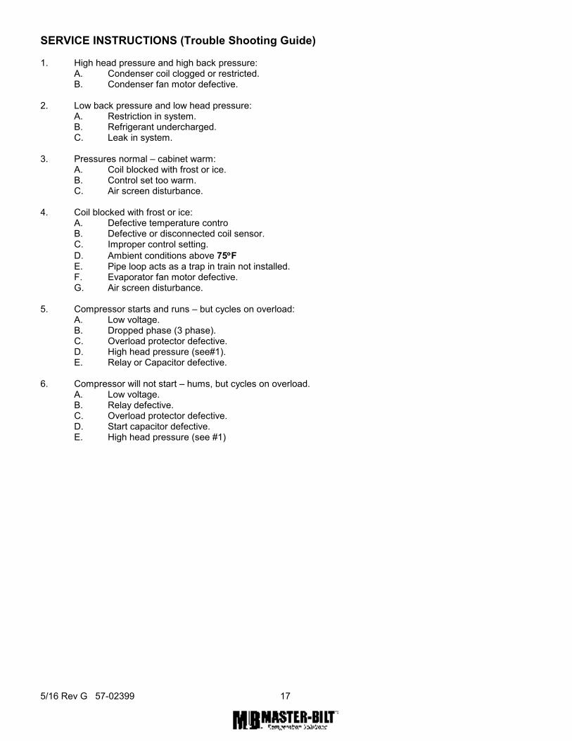
SERVICE INSTRUCTIONS (Trouble Shooting Guide) 1. High head pressure and high back pressure:
A. Condenser coil clogged or restricted. B. Condenser fan motor defective.
2. Low back pressure and low head pressure: A. Restriction in system. B. Refrigerant undercharged. C. Leak in system.
3. Pressures normal – cabinet warm: A. Coil blocked with frost or ice. B. Control set too warm. C. Air screen disturbance.
4. Coil blocked with frost or ice:
A. Defective temperature contro B. Defective or disconnected coil sensor. C. Improper control setting.
D. Ambient conditions above 75°°°°F E. Pipe loop acts as a trap in train not installed. F. Evaporator fan motor defective. G. Air screen disturbance.
5. Compressor starts and runs – but cycles on overload: A. Low voltage. B. Dropped phase (3 phase). C. Overload protector defective. D. High head pressure (see#1). E. Relay or Capacitor defective.
6. Compressor will not start – hums, but cycles on overload.
A. Low voltage. B. Relay defective. C. Overload protector defective. D. Start capacitor defective. E. High head pressure (see #1)

5/16 Rev G 57-02399 18
MASTER-BILT® PART NUMBERS
The tables below list Master-Bilt®
part numbers. Use this chart when ordering replacement parts for your OAM(VOAM
AND/OR HOAM) cases. All quantities are one each unless otherwise noted by parentheses.
Description VOAM 36-60 VOAM 48-60 VOAM 60-60 VOAM 72-60
Compressor 03-15379 03-15378 03-15372 03-15372
Condensate Pan 17-09589 17-09589 17-09590 17-09590
Condenser Coil 07-14088 07-14089 07-14112 07-14112
Condenser Fan Blade 15-13093 15-13093 15-13093 15-13093
Condenser Fan Motor 13-00311 13-00311 13-00311 13-00311
Contactor 19-13936 19-13936 19-13936 19-13936
Drier 09-09171 09-09171 09-09711 09-09711
Evaporator Coil 07-14113 07-14114 07-14115 07-14116
Evaporator Fan Blade 15-13094 15-13094 15-13094 15-13094
Evaporator Fan Motor 13-13181 13-13181 13-13181 13-13181
Electronic Controller 19-14243 19-14243 19-14243 19-14243
Box Sensor T1 19-14244 19-14244 19-14244 19-14244
Expansion Valve 09-10345 09-10346 09-10347 09-10347
Female Plug 21-01488 21-01488 21-01488 21-01488
LED Driver (Convertor) 23-01778 23-01810 23-01810 23-01810
LED Light Bar End Caps 23-01771 23-01771 23-01771 23-01771
LED Light Bar Power Cord
23-01772 23-01772 23-01772 23-01772
LED Light Bar, 18" --- --- 23-01760 ---
LED Light Bar, 24" 23-01764 --- --- 23-01764
LED Light Bar, 36" --- 23-01763 --- ---
Light Switch 23-50793 23-50793 23-50793 23-50793
Thermometer 44-00963 44-00963 44-00963 44-00963
Refrigerant (R-404a) 30 oz. 32 oz. 53 oz. 58 oz.

5/16 Rev G 57-02399 19
Description VOAM 36-72 VOAM 48-72 VOAM 60-72 VOAM 72-72
Compressor 03-15378 03-15372 03-15217 03-15217
Condensate Pan 17-09590 17-09590 17-09591 17-09591
Condenser Coil 07-14089 07-14112 07-14112 07-14112
Condenser Fan Blade 15-13093 15-13093 15-13093 15-13093
Condenser Fan Motor 13-00311 13-00311 13-01283 13-01283
Contactor 19-13936 19-13936 19-13934 19-13934
Drier 09-09171 09-09711 09-09711 09-09711
Evaporator Coil 07-14113 07-14114 07-14115 07-14116
Evaporator Fan Blade 15-13094 15-13094 15-13094 15-13094
Evaporator Fan Motor 13-13181 13-13181 13-13181 13-13181
Electronic Controller 19-14243 19-14243 19-14243 19-14243
Box Sensor T1 19-14244 19-14244 19-14244 19-14244
Expansion Valve 09-10346 09-10347 09-10347 09-10347
Female Plug 21-01488 21-01488 21-01488 21-01488
LED Driver (Convertor) 23-01810 23-01810 23-01814 23-01814
LED Light Bar End Caps 23-01771 23-01771 23-01771 23-01771
LED Light Bar Power Cord
23-01772 23-01772 23-01772 23-01772
LED Light Bar, 18" --- -- 23-01760 ---
LED Light Bar, 24" 23-01764 --- --- 23-01764
LED Light Bar, 36" --- 23-01763 --- ---
Light Switch 23-50793 23-50793 23-50793 23-50793
Thermometer 44-00963 44-00963 44-00963 44-00963
Refrigerant (R-404a) 22 oz. 48 oz. 40 oz. 60 oz.

5/16 Rev G 57-02399 20
Description VOAM 36-79 VOAM 48-79 VOAM 60-79 VOAM 72-79
Compressor 03-15378 03-15372 03-15217 03-15217
Condensate Pan 17-09590 17-09590 17-09591 17-09591
Condenser Coil 07-14089 07-14112 07-14112 07-14112
Condenser Fan Blade 15-13093 15-13093 15-13093 15-13093
Condenser Fan Motor 13-00311 13-00311 13-01283 13-01283
Contactor 19-13936 19-13936 19-13934 19-13934
Drier 09-09171 09-09711 09-09711 09-09711
Evaporator Coil 07-14113 07-14114 07-14115 07-14116
Evaporator Fan Blade 15-13094 15-13094 15-13094 15-13094
Evaporator Fan Motor 13-13181 13-13181 13-13181 13-13181
Electronic Controller 19-14243 19-14243 19-14243 19-14243
Box Sensor T1 19-14244 19-14244 19-14244 19-14244
Expansion Valve 09-10346 09-10347 09-10347 09-10347
Female Plug 21-01488 21-01488 21-01488 21-01488
LED Driver (Convertor) 23-01810 23-01814 23-01814 23-01814
LED Light Bar End Caps 23-01771 23-01771 23-01771 23-01771
LED Light Bar Power Cord 23-01772 23-01772 23-01772 23-01772
LED Light Bar, 18" --- --- 23-01760 ---
LED Light Bar, 24" 23-01764 --- --- 23-01764
LED Light Bar, 36" --- 23-01763 --- ---
Light Switch 23-50793 23-50793 23-50793 23-50793
Thermometer 44-00963 44-00963 44-00963 44-00963
Refrigerant (R-404a) 22 oz. 48 oz. 40 oz. 60 oz.

5/16 Rev G 57-02399 21
Description HOAM 36 HOAM 48 HOAM 60 HOAM 72
Compressor 03-15379 03-15379 03-15378 03-15378
Condensate Pan 17-09589 17-09589 17-09590 17-09590
Condenser Coil 07-14088 07-14088 07-14089 07-14089
Condenser Fan Blade 15-13093 15-13093 15-13093 15-13093
Condenser Fan Motor 13-00311 13-00311 13-00311 13-00311
Contactor 19-13936 19-13936 19-13936 19-13936
Drier 09-09171 09-09171 09-09171 09-09171
Evaporator Coil 07-14117 07-14118 07-14119 07-14120
Evaporator Fan Blade 15-13132 15-13132 15-13132 15-13132
Evaporator Fan Motor 13-13181 13-13181 13-13181 13-13181
Electronic Controller 19-14243 19-14243 19-14243 19-14243
Box Sensor T1 19-14244 19-14244 19-14244 19-14244
Expansion Valve 09-10345 09-10345 09-10346 09-10346
Female Plug 21-01488 21-01488 21-01488 21-01488
LED Driver (Convertor) 23-01878 23-01878 23-01778 23-01778
LED Light Bar End Caps 23-01771 23-01771 23-01771 23-01771
LED Light Bar Power Cord 23-01772 23-01772 23-01772 23-01772
LED Light Bar, 18" --- --- 23-01760 ---
LED Light Bar, 24" 23-01764 --- --- 23-01764
LED Light Bar, 36" --- 23-01763 --- ---
Light Switch 23-50793 23-50793 23-50793 23-50793
Thermometer 44-00963 44-00963 44-00963 44-00963
Refrigerant (R-404a) 40 oz. 36 oz. 36 oz. 38 oz.

5/16 Rev G 57-02399 22
ACCESSORIES LIST
Description VOAM 36-60 VOAM 48-60 VOAM 60-60 VOAM 72-60
Shelf Assembly 499-718-BS 500-718-BS 501-718-BS 502-718-BS
Shelf Lighting Assembly A491-718-BL A492-718-BL A493-718-BL A494-718-BL
Condensate Pump 61-00891 61-00891 61-00891 61-00891
Casters 2" Diameter A039-11140 A039-11140 A044-11140 A044-11140
Description VOAM 36-72 VOAM 48-72 VOAM 60-72 VOAM 72-72
Shelf Assembly 499-718-BS 500-718-BS 501-718-BS 502-718-BS
Shelf Lighting Assembly A495-718-BL A496-718-BL A497-718-BL A498-718-BL
Condensate Pump 61-00891 61-00891 61-00891 61-00891
Casters 2" Diameter A039-11140 A039-11140 A044-11140 A044-11140
Description VOAM 36-79 VOAM 48-79 VOAM 60-79 VOAM 72-79
Shelf Assembly 499-718-BS 500-718-BS 501-718-BS 502-718-BS
Shelf Lighting Assembly A499-718-BL A500-718-BL A501-718-BL A502-718-BL
Condensate Pump 61-00891 61-00891 61-00891 61-00891
Casters 2" Diameter A039-11140 A039-11140 A044-11140 A044-11140
Description HOAM 36 HOAM 48 HOAM 60 HOAM 72
Shelf Assembly 503-710-BS 504-710-BS 505-710-BS 506-710-BS
Condensate Pump 61-00891 61-00891 61-00891 61-00891
Casters 2" Diameter A039-11140 A039-11140 A044-11140 A044-11140

5/16 Rev G 57-02399 23
SALE AND DISPOSAL
OWNER RESPONSIBILITY
If you sell or give away your Master-Bilt®
cabinet you must make sure that all safety labels and the Installation -
Service Manual are included with it. If you need replacement labels or manuals, Master-Bilt will provide them free. Contact the customer service department at Master-Bilt at (800) 684-8988. The customer service department at Master-Bilt should be contacted at the time of sale or disposal of your cabinet so records may be kept of its new location.
If you sell or give away your Master-Bilt®
cabinet and you evacuate the refrigerant charge before shipment, Master-Bilt
recommends that the refrigerant charge be properly recovered in complience with section 608 of the Clean Air Act effective November 1995 and in accordance with all applicable local, regional, or national standards.

5/16 Rev G 57-02399 24
DESCRIPTION
DATE
MODEL(S)
DRAWN BY
V36-60,V48-60,V60-60,V72-60,V36-72
V48-72,V36-79,V48-79,H36,H48,H60,H72
115V, LAE AT2 CONTROL
BGH
4/7/14

5/16 Rev G 57-02399 25
DESCRIPTION
DATE
MODEL(S)
DRAWN BY
V60-72, V72-72, V60-79, V72-79
220V, LAE AT2 CONTROL
BGH
4/7/14

5/16 Rev G 57-02399 26
DESCRIPTION
DATE
MODEL(S)
DRAWN BY
V48-79
220V, LAE AT2 CONTROL
BGH
4/7/14

5/16 Rev G 57-02399 27
DESCRIPTION
DATE
REMOTE LAE AT2 CONTROL
5/2/14
MODEL(S)
DRAWN BY
ALL VOAM & HOAM
BGH

5/16 Rev G 57-02399 28
DESCRIPTION
DATE
MODEL(S)
DRAWN BY
V48-60,V60-60,V72-60,V36-72
V48-72,V36-79,V48-79,H60,H72
CANADA CABINETS ONLY
115V, LAE AT2 CONTROL
BGH
7/16/14

5/16 Rev G 57-02399 0