Embed Size (px)
Citation preview
ZX10 “ST” MODEL
ELECTRIC WIRE ROPE HOIST
INSTALLATION, OPERATION AND
MAINTENANCE INSTRUCTIONS
56565656defgh Street Crane Company Limited reserves the right to alter or amend the details given in this publication without prior notification.
© Street Crane Company Limited 2014 Document Ref: D3050 rev. D

defgh © Street Crane Co Ltd
III
INTRODUCTION This manual has been carefully prepared to assist you in the installation, maintenance and safe operation of the Street Crane equipment as described in the manual. It is in the interest of all parties involved with the use of this equipment to ensure that procedures are followed efficiently and safely. Before installing, using or starting any maintenance work on the hoist study this manual carefully. Obtain a complete understanding of the hoist and its controls in order to ensure the safe and efficient use of the hoist. Ensure that all persons involved in the operation are suitably qualified and trained in its safe operation. Provided that the recommended operation, maintenance and lubrication procedures are followed, you will maximise the Hoist’s life expectancy and have trouble free service. Anyone working with or on the equipment should also be aware of their relevant responsibilities under the Factories Act, the Health and Safety at Work Act 1974 and Lifting Operations and Lifting Equipment Regulations (LOLER) 1998. The user has the responsibility for ensuring that the equipment is properly inspected and maintained and is safe to use. NOTE: Other national regulations may apply for other countries. In Great Britain codes of practice exist for the “Safe Use of Cranes”. This standard, BS 7121, also covers inspection, testing and examination. The user should be familiar with its contents and it is advisable to have a copy of this standard kept alongside this manual. BS 7121 covers the following subjects:‐
Safe systems of work
Management of the lifting operation
Planning of the lifting operation, risk assessments and method statements
Selection and duties of personnel and their minimum attributes
Maintenance of cranes
Inspection, Testing and Examination
In addition, management and supervision have an initial role to play in any safety programme by ensuring that:‐
The equipment is suitable for the job intended
The equipment has been thoroughly examined and is safe to use
A safety procedure is adopted for emergency situations i.e. power failure
A safe system of work is adopted for maintenance personnel It should be emphasised that the safety advice and maintenance details included in this document should be made available where they can be most effective. It is your responsibility to ensure that this information is made available at THE PLACE OF WORK.

defgh © Street Crane Co Ltd
IV
THIS PAGE IS INTENTIONALLY BLANK
defgh © Street Crane Co Ltd
V
CONTENTS
1. GENERAL SAFETY INSTRUCTIONS .......................................................................................................... 9 1.1 SYMBOLS .............................................................................................................................................. 9 1.2 PERSONNEL ‐ Definitions and Attributes ............................................................................................. 9 1.3 MAINTENANCE SAFETY PROCEDURE ................................................................................................... 9 1.4 MAINTENANCE AND INSPECTION ACCESS ......................................................................................... 10 1.5 WARRANTY / REPLACEMENT PARTS .................................................................................................. 10 1.6 PERIODIC TESTS .................................................................................................................................. 10 1.7 STORAGE ............................................................................................................................................ 10 1.8 TRAINING AND AFTER SALES SERVICE ............................................................................................... 10
2 DESCRIPTION OF EQUIPMENT ............................................................................................................. 11 2.1 HOIST NAMEPLATE ............................................................................................................................ 12 2.2 LIMITING DEVICES .............................................................................................................................. 12
2.2.1 Hoisting and lowering limits .......................................................................................................... 12 2.2.2 Rated capacity limiter (RCL) .......................................................................................................... 13 2.2.3 Travel / Traverse limits (optional) ................................................................................................. 13
3 INSTALLATION AND COMMISSIONING INSTRUCTIONS ........................................................................ 14 3.1 TRAVERSE END STOPS ........................................................................................................................ 14 3.2 RUNNING & MOUNTING SURFACE TOLERANCES AND FINISHES ....................................................... 14
3.2.1 Tolerances on the Inclination of the Running Surface .................................................................. 14 3.2.2 Tolerances on Crab Rail Gauge & Rail Height ................................................................................ 15 3.2.3 Tolerances on Mounting Surface for Foot Mounted Hoists .......................................................... 15 3.2.4 Tolerance on misalignment of rail joints, wheel running surfaces and guidance surfaces ........... 15
3.3 HOIST WEIGHTS AND LIFTING POINTS ............................................................................................... 16 3.3.1 Foot Mount ................................................................................................................................... 16 3.3.2 Double Girder Crab ....................................................................................................................... 18
3.4 INSTALLATION OF FOOT MOUNTED HOIST ........................................................................................ 20 3.5 SETTING THE ROTARY LIMIT SWITCH FOR UPPER AND LOWER LIMITS ............................................. 21
3.5.1 Setting the upper limit .................................................................................................................. 21 3.5.2 Setting the lower limit ................................................................................................................... 22
3.6 ULTIMATE UPPER LIMIT SWITCH ‐ ROTARY (OPTIONAL) ................................................................... 24 3.6.1 Setting the ultimate upper limit‐ ROTARY (OPTIONAL) ................................................................. 25
3.7 ULTIMATE UPPER LIMIT SWITCH – HOOK BLOCK OPERATED (OPTIONAL) ........................................ 26 3.7.1 Setting the ultimate upper limit .................................................................................................... 26
3.8 ZX10 FOOT MOUNT HIGHEST HOOK POSITION ................................................................................. 27 3.9 ZX10 DOUBLE GIRDER CRAB HIGHEST HOOK POSITION .................................................................... 27 3.10 CHECKING / ADJUSTING THE RATED CAPACITY LIMITER ................................................................... 28
3.10.1 Adjusting the Rated Capacity Limiter for Proof Loading .......................................................... 28 3.11 TRAVERSE LIMITS (OPTIONAL) ........................................................................................................... 29
3.11.1 Setting traverse limits ............................................................................................................... 29 3.12 CONNECTING THE POWER SUPPLY .................................................................................................... 31
3.12.1 Supply cables / fuses ................................................................................................................ 31 3.12.2 Main isolator – supply switch (by others) ................................................................................ 31 3.12.3 Connecting to the mains supply ............................................................................................... 31 3.12.4 Electro‐magnetic compatibility ................................................................................................ 33
3.13 COMMISSIONING PROCEDURE .......................................................................................................... 33 3.14 DISMANTLING / REMOVAL OF THE HOIST ......................................................................................... 33
defgh © Street Crane Co Ltd
VI
4 OPERATING INSTRUCTIONS ................................................................................................................ 35 4.1 INTENDED USE ................................................................................................................................... 35 4.2 DUTIES OF THE OPERATOR / SAFE HOISTING PRACTICES .................................................................. 35 4.3 REMOTE CONTROLLED CRANES / HOISTS .......................................................................................... 37 4.4 CONTROL STATION OPERATING INSTRUCTIONS ................................................................................ 38
4.4.1 Legend Nomenclature ................................................................................................................... 38 4.4.2 Switch ON ...................................................................................................................................... 38 4.4.3 Push button operation .................................................................................................................. 38 4.4.4 Joystick operation ......................................................................................................................... 39 4.4.5 Emergency Stop ............................................................................................................................ 40
4.5 LEAVING THE CRANE / HOIST UNATTENDED ..................................................................................... 41 4.6 POWER FAILURE ................................................................................................................................. 41
5 INSPECTION AND MAINTENANCE INSTRUCTIONS ................................................................................ 42 5.1 REPORTING OF DEFECTS AND INCIDENTS .......................................................................................... 42 5.2 SPECIAL KNOWLEDGE ........................................................................................................................ 42 5.3 KEEPING OF RECORDS ........................................................................................................................ 42 5.4 DAILY PRE‐USE INSPECTIONS (at the start of each day/shift) ............................................................ 42 5.5 HOISTS THAT HAVE BEEN UNUSED FOR AN EXTENDED PERIOD ....................................................... 43 5.6 INSPECTION AND MAINTENANCE INTERVALS ................................................................................... 44 5.7 LUBRICATION ..................................................................................................................................... 47
5.7.1 Lubrication schedule ..................................................................................................................... 48 5.8 INSPECTION AND MAINTENANCE – WIRE ROPE ................................................................................ 50
5.8.1 Offloading and Storage ................................................................................................................. 50 5.8.2 Replacing the Wire Rope ............................................................................................................... 50
5.9 INSPECTION AND MAINTENANCE ...................................................................................................... 54 5.9.1 Sheaves ......................................................................................................................................... 54 5.9.2 Double Girder Crab Wheels (Double Flange) ................................................................................ 55
5.10 INSPECTION AND MAINTENANCE – HOIST BRAKE ............................................................................. 56 5.10.1 Hoist Brake Components .......................................................................................................... 56 5.10.2 Hoist Brake Data ....................................................................................................................... 57 5.10.3 Brake Disc (Rotor) Spline .......................................................................................................... 57 5.10.4 Checking / Adjusting the Air Gap .............................................................................................. 57 5.10.5 Changing the Brake Disc (brake rotor) / Inspecting the brake hub .......................................... 58 5.10.6 Fitting the Hand Release .......................................................................................................... 59 5.10.7 Fitting the brake seal kit (optional) .......................................................................................... 60 5.10.8 Brake rectifier ........................................................................................................................... 60
5.11 INSPECTION AND MAINTENANCE – TRAVERSE BRAKE ...................................................................... 61 5.11.1 Traverse Brake Components .................................................................................................... 61 5.11.2 Checking / Adjusting the Air Gap .............................................................................................. 62 5.11.3 Changing the Brake Disc (brake rotor) / Inspecting the brake hub .......................................... 62 5.11.4 Fitting the Traverse Drive Hand Release .................................................................................. 63 5.11.5 Fitting the brake seal kit (optional) .......................................................................................... 63
5.12 INSPECTION AND MAINTENANCE – HOOK BLOCK ............................................................................. 64 5.13 INSPECTION AND MAINTENANCE – HOIST DRIVE COUPLING ............................................................ 67
6 FAULT FINDING .................................................................................................................................. 68 6.1 GENERAL ............................................................................................................................................ 68 6.2 BRAKES ............................................................................................................................................... 69
defgh © Street Crane Co Ltd
VII
6.3 MOTOR UNITS .................................................................................................................................... 70 6.4 GEARBOXES ........................................................................................................................................ 70
7 TECHNICAL DATA ................................................................................................................................ 71 7.1 CONDITIONS OF USE .......................................................................................................................... 71 7.2 PROCEDURE FOR ESTIMATING REMAINING SERVICE LIFE ................................................................. 71 7.3 HOIST MODEL CODE .......................................................................................................................... 72 7.4 NOISE LEVELS ..................................................................................................................................... 75 7.5 HOIST MOTOR DATA .......................................................................................................................... 76
7.5.1 ZX10 Hoist Motor Data – 4:1 SPEED RATIO ‐ 400V, 3Ph, 50Hz ...................................................... 76 7.5.2 ZX10 Hoist Motor Data – 4:1 SPEED RATIO ‐ 460V, 3Ph, 60Hz ...................................................... 77 7.5.3 ZX10 Hoist Motor Data – 4:1 SPEED RATIO ‐ 575V, 3Ph, 60Hz ...................................................... 78 7.5.4 ZX10 Hoist Motor Data – 4:1 SPEED RATIO ‐ 380V, 3Ph, 60Hz ...................................................... 79 7.5.5 ZX Dual Wound ‘WU’ Type Traverse Motor Data‐ 400V, 3Ph, 50Hz ............................................. 80 7.5.6 ZX Dual Wound ‘WU’ Type Traverse Motor Data‐ 460V, 3Ph, 60Hz ............................................. 81 7.5.7 ZX Dual Wound ‘WU’ Type Traverse Motor Data‐ 575V, 3Ph, 60Hz ............................................. 82 7.5.8 ZX Dual Wound ‘WU’ Type Traverse Motor Data‐ 380V, 3Ph, 60Hz ............................................. 83 7.5.9 ZX Traverse Motor Data for use with Frequency Inverter ............................................................ 84
7.6 CABLE CROSS SECTION AND LENGTH OF SUPPLY CABLE ................................................................... 85 7.7 RESULTS OF PERIODIC TESTS.............................................................................................................. 86 7.8 RECORD OF REPLACEMENT PARTS (ropes, brakes, sheaves etc.) ...................................................... 87
FIGURES
Figure 1 – Hoist Nameplate Location .................................................................................................................... 12 Figure 2 – Double Girder Crab Traverse End Stops ............................................................................................... 14 Figure 3 – Double Girder Runway Tolerances ....................................................................................................... 15 Figure 4 – Foot Mount Lifting Eyes‐ 4,8,12 & 16 fall units .................................................................................... 16 Figure 5 – Removing Hoist Cover/Covers on 4,8,12 and 16 fall Foot Mount and Double Girder Crabs ............... 16 Figure 6 – Double Girder Crab Lifting Eyes‐ 4,8,12 and 16 fall units ..................................................................... 18 Figure 7 – Installation of Foot Mounted Hoist ...................................................................................................... 20 Figure 8 –Upper and Lower Limit Rotary Type ...................................................................................................... 21 Figure 9 – Setting the Upper Limit Switch – Rotary Limit Switch .......................................................................... 22 Figure 10 – Ultimate Upper Limit Switch – Rotary Type ....................................................................................... 24 Figure 11 – Setting the Ultimate Upper Limit Switch – Rotary Type .................................................................... 25 Figure 12 – Ultimate Upper Limit Switch – Hook Block Type ................................................................................ 26 Figure 13 – Rated Capacity Limiter ....................................................................................................................... 28 Figure 14 – Setting the Traverse Limit .................................................................................................................. 29 Figure 15 – Traverse Limit Double Girder arrangement ....................................................................................... 30 Figure 16 – Hoist Electrical Connections ............................................................................................................... 31 Figure 17 – Delay Timers ....................................................................................................................................... 32 Figure 18 – Phase Failure Relay ............................................................................................................................. 32 Figure 19 – Control Transformer Connections ...................................................................................................... 33 Figure 20 – Clearances to consider when lifting ................................................................................................... 36 Figure 21 ‐ Recommended Hand Signals ............................................................................................................... 37 Figure 22 – Control Pendant Legends ................................................................................................................... 38 Figure 23 – Gearbox oil fill & level plug locations ................................................................................................. 47 Figure 24 – Correct uncoiling of wire ropes .......................................................................................................... 51
defgh © Street Crane Co Ltd
VIII
Figure 25 ‐ Incorrect uncoiling of wire ropes ........................................................................................................ 51 Figure 26 – Fleet angle .......................................................................................................................................... 52 Figure 27 – Reeving Diagrams for ZX10 ST 4 Fall Foot Mount and Double Girder Crab ....................................... 52 Figure 28 – Reeving Diagrams for ZX10 ST 8 Fall Foot Mount and Double Girder Crab ....................................... 52 Figure 29 – Reeving Diagrams for ZX10 ST 12 Fall Foot Mount and Double Girder Crab ..................................... 53 Figure 30 – Reeving Diagrams for ZX10 ST 16 Fall Foot Mount and Double Girder Crab ..................................... 53 Figure 31 ‐ Sheave characteristics‐ 13mm rope .................................................................................................... 54 Figure 32 – Sheave and barrel groove inspection ................................................................................................. 54 Figure 33 – Hoist Brake Components .................................................................................................................... 56 Figure 34 – Checking Hoist Brake Air Gap ............................................................................................................. 57 Figure 35 – Adjusting the Hoist Brake Air Gap ...................................................................................................... 58 Figure 36 – Inspecting the Brake Disc ................................................................................................................... 58 Figure 37 – Hoist Brake Hand Release .................................................................................................................. 59 Figure 38 – Brake Seal ........................................................................................................................................... 60 Figure 39 – Traverse Brake Components .............................................................................................................. 61 Figure 40 – Checking Traverse Brake Air Gap ....................................................................................................... 62 Figure 41 – Adjusting the Traverse Brake Air Gap ................................................................................................ 62 Figure 42 – Traverse Drive Brake Hand Release ................................................................................................... 63 Figure 43 – Traverse Drive Brake Seal ................................................................................................................... 63 Figure 44 – Hook Throat Admittance .................................................................................................................... 64 Figure 45 – 4 Fall Bottom Block, Hook Nut, Grubscrew, Grease nipple ................................................................ 65 Figure 46 – 8 Fall Bottom Block, Hook Nut, Grubscrew, Grease nipple ............................................................... 65 Figure 47 – 12 Fall Bottom Block, Hook Nut, Grubscrew, Grease nipple ............................................................. 65 Figure 48 – 16 Fall Bottom Block, Hook Nut, Grubscrew, Grease nipple ............................................................. 66 Figure 49 – Sound Pressure Levels ........................................................................................................................ 75
defgh © Street Crane Co Ltd
Ref: D3050 Rev D Page 9 of 93
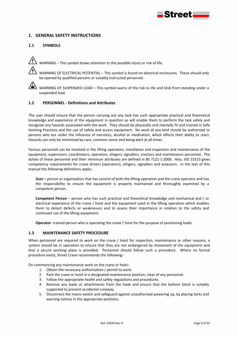
1. GENERAL SAFETY INSTRUCTIONS
1.1 SYMBOLS
1 WARNING – This symbol draws attention to the possible injury or risk of life.
2 WARNING OF ELECTRICAL POTENTIAL – This symbol is found on electrical enclosures. These should only be opened by qualified persons or suitably instructed personnel.
3 WARNING OF SUSPENDED LOAD – This symbol warns of the risk to life and limb from standing under a suspended load.
1.2 PERSONNEL ‐ Definitions and Attributes
The user should ensure that the person carrying out any task has such appropriate practical and theoretical knowledge and experience of the equipment in question as will enable them to perform the task safely and recognise any hazards associated with the work. They should be physically and mentally fit and trained in Safe Hoisting Practices and the use of safety and access equipment. No work of any kind should be authorised to persons who are under the influence of narcotics, alcohol or medication, which affects their ability to react. Hazards can only be minimised by care, common sense and being alert at all times. Various personnel can be involved in the lifting operation, installation and inspection and maintenance of the equipment, supervisors, coordinators, operators, slingers, signallers, erectors and maintenance personnel. The duties of these personnel and their minimum attributes are defined in BS 7121‐1:2006. Also, ISO 15513 gives competency requirements for crane drivers (operators), slingers, signallers and assessors. In the text of this manual the following definitions apply:‐
User – person or organisation that has control of both the lifting operation and the crane operator and has the responsibility to ensure the equipment is properly maintained and thoroughly examined by a competent person. Competent Person – person who has such practical and theoretical knowledge and mechanical and / or electrical experience of the crane / hoist and the equipment used in the lifting operation which enables them to detect defects or weaknesses and to assess their importance in relation to the safety and continued use of the lifting equipment. Operator‐ trained person who is operating the crane / hoist for the purpose of positioning loads.
1.3 MAINTENANCE SAFETY PROCEDURE
When personnel are required to work on the crane / hoist for inspection, maintenance or other reasons, a system should be in operation to ensure that they are not endangered by movement of the equipment and that a secure working place is provided. Personnel should follow such a procedure. Where no formal procedure exists, Street Crane recommends the following:‐ On commencing any maintenance work on the crane or hoist:‐
1. Obtain the necessary authorisation / permit to work. 2. Park the crane or hoist in a designated maintenance position, clear of any personnel. 3. Follow the appropriate health and safety regulations and procedures. 4. Remove any loads or attachments from the hook and ensure that the bottom block is suitably
supported to prevent accidental runaway. 5. Disconnect the mains switch and safeguard against unauthorised powering up, by placing locks and
warning notices in the appropriate positions.
defgh © Street Crane Co Ltd
Page 10 of 93 Ref: D3050 rev. D
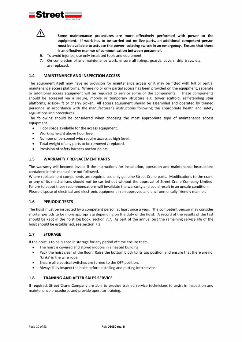
1 Some maintenance procedures are more effectively performed with power to the equipment. If work has to be carried out on live parts, an additional competent person must be available to actuate the power isolating switch in an emergency. Ensure that there is an effective manner of communication between personnel.
6. To avoid injuries, use only insulated tools and equipment. 7. On completion of any maintenance work, ensure all fixings, guards, covers, drip trays, etc.
are replaced.
1.4 MAINTENANCE AND INSPECTION ACCESS
The equipment itself may have no provision for maintenance access or it may be fitted with full or partial maintenance access platforms. Where no or only partial access has been provided on the equipment, separate or additional access equipment will be required to service some of the components. These components should be accessed via a secure, mobile or temporary structure e.g. tower scaffold, self‐standing stair platforms, scissor‐lift or cherry picker. All access equipment should be assembled and operated by trained personnel in accordance with the manufacturer’s instructions following the appropriate health and safety regulations and procedures. The following should be considered when choosing the most appropriate type of maintenance access equipment.
Floor space available for the access equipment.
Working height above floor level.
Number of personnel who require access at high level.
Total weight of any parts to be removed / replaced.
Provision of safety harness anchor points
1.5 WARRANTY / REPLACEMENT PARTS
The warranty will become invalid if the instructions for installation, operation and maintenance instructions contained in this manual are not followed. Where replacement components are required use only genuine Street Crane parts. Modifications to the crane or any of its mechanisms should not be carried out without the approval of Street Crane Company Limited. Failure to adopt these recommendations will invalidate the warranty and could result in an unsafe condition. Please dispose of electrical and electronic equipment in an approved and environmentally friendly manner.
1.6 PERIODIC TESTS
The hoist must be inspected by a competent person at least once a year. The competent person may consider shorter periods to be more appropriate depending on the duty of the hoist. A record of the results of the test should be kept in the hoist log book, section 7.7. As part of the annual test the remaining service life of the hoist should be established, see section 7.2.
1.7 STORAGE
If the hoist is to be placed in storage for any period of time ensure that:‐
The hoist is covered and stored indoors in a heated building.
Pack the hoist clear of the floor. Raise the bottom block to its top position and ensure that there are no ‘kinks’ in the wire rope.
Ensure all electrical switches are turned to the OFF position.
Always fully inspect the hoist before installing and putting into service.
1.8 TRAINING AND AFTER SALES SERVICE
If required, Street Crane Company are able to provide trained service technicians to assist in inspection and maintenance procedures and provide operator training.
defgh © Street Crane Co Ltd
Ref: D3050 rev. D Page 11 of 93
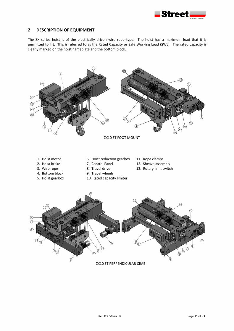
2 DESCRIPTION OF EQUIPMENT
The ZX series hoist is of the electrically driven wire rope type. The hoist has a maximum load that it is permitted to lift. This is referred to as the Rated Capacity or Safe Working Load (SWL). The rated capacity is clearly marked on the hoist nameplate and the bottom block.
1. Hoist motor 6. Hoist reduction gearbox 11. Rope clamps2. Hoist brake 7. Control Panel 12. Sheave assembly 3. Wire rope 8. Travel drive 13. Rotary limit switch 4. Bottom block 9. Travel wheels5. Hoist gearbox 10. Rated capacity limiter
ZX10 ST PERPENDICULAR CRAB
ZX10 ST FOOT MOUNT
defgh © Street Crane Co Ltd
Page 12 of 93 Ref: D3050 rev. D
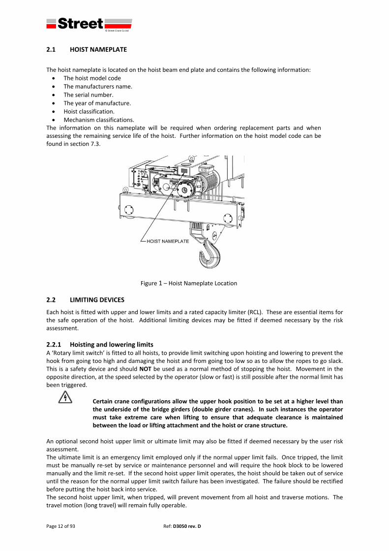
2.1 HOIST NAMEPLATE
The hoist nameplate is located on the hoist beam end plate and contains the following information:
The hoist model code
The manufacturers name.
The serial number.
The year of manufacture.
Hoist classification.
Mechanism classifications. The information on this nameplate will be required when ordering replacement parts and when assessing the remaining service life of the hoist. Further information on the hoist model code can be found in section 7.3.
Figure 1 – Hoist Nameplate Location
2.2 LIMITING DEVICES
Each hoist is fitted with upper and lower limits and a rated capacity limiter (RCL). These are essential items for the safe operation of the hoist. Additional limiting devices may be fitted if deemed necessary by the risk assessment.
2.2.1 Hoisting and lowering limits A ‘Rotary limit switch’ is fitted to all hoists, to provide limit switching upon hoisting and lowering to prevent the hook from going too high and damaging the hoist and from going too low so as to allow the ropes to go slack. This is a safety device and should NOT be used as a normal method of stopping the hoist. Movement in the opposite direction, at the speed selected by the operator (slow or fast) is still possible after the normal limit has been triggered.
2 Certain crane configurations allow the upper hook position to be set at a higher level than the underside of the bridge girders (double girder cranes). In such instances the operator must take extreme care when lifting to ensure that adequate clearance is maintained between the load or lifting attachment and the hoist or crane structure.
An optional second hoist upper limit or ultimate limit may also be fitted if deemed necessary by the user risk assessment. The ultimate limit is an emergency limit employed only if the normal upper limit fails. Once tripped, the limit must be manually re‐set by service or maintenance personnel and will require the hook block to be lowered manually and the limit re‐set. If the second hoist upper limit operates, the hoist should be taken out of service until the reason for the normal upper limit switch failure has been investigated. The failure should be rectified before putting the hoist back into service. The second hoist upper limit, when tripped, will prevent movement from all hoist and traverse motions. The travel motion (long travel) will remain fully operable.
defgh © Street Crane Co Ltd
Ref: D3050 rev. D Page 13 of 93
A red warning light on the base of the control panel will illuminate to indicate when the second ultimate limit has been activated.
2.2.2 Rated capacity limiter (RCL) All hoist units are fitted with a rated capacity limiter (RCL) to prevent the lifting of loads beyond the capacity of the hoist / crane. If the RCL is tripped the hoist motion will stop and it will then only be possible to move in the lower direction.
2.2.3 Travel / Traverse limits (optional) Limit switches at the extremes of long and cross travel are optional based on the user’s risk assessment. There are three types:‐
1. On reaching the limit the crane or hoist travel motion will stop altogether. 2. On reaching the limit the crane or hoist will change from fast to slow speed and proceed at slow
speed until the end stop is reached. 3. If a two stage limit is fitted, on reaching the first stage the motion will reduce to slow speed. On
reaching the second stage the motion will stop. Operation of the limit does not have any effect on other crane motions. Movement in the opposite direction, at the speed selected by the operator (slow or fast) is still possible after the limit has been triggered.
defgh © Street Crane Co Ltd
Page 14 of 93 Ref: D3050 rev. D
3 INSTALLATION AND COMMISSIONING INSTRUCTIONS
Installation and commissioning of the hoist must be carried out by a competent person(s). We recommend that installation and commissioning are carried out by Street Crane Company or their approved agents. Immediately report any damage which may have occurred during transit. Consult with the manufacturer / supplier and repair the equipment before installation. Do not install damaged equipment. Use only original Street Crane spare parts for repairs. Do not carry out any alterations or modifications to the hoist either prior to or during installation. If the hoist is located outdoors we recommend that a small cover (roof) is fitted to the runway beam to protect the hoist at its parking position.
3.1 TRAVERSE END STOPS
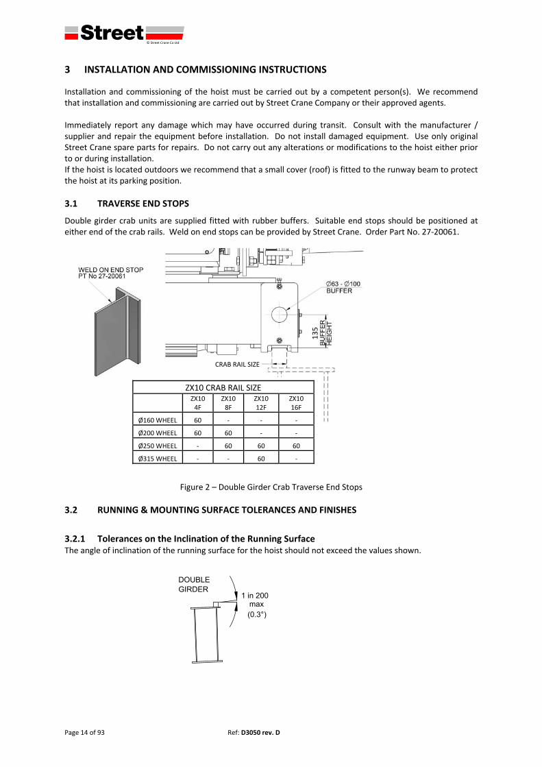
Double girder crab units are supplied fitted with rubber buffers. Suitable end stops should be positioned at either end of the crab rails. Weld on end stops can be provided by Street Crane. Order Part No. 27‐20061.
Figure 2 – Double Girder Crab Traverse End Stops
3.2 RUNNING & MOUNTING SURFACE TOLERANCES AND FINISHES
3.2.1 Tolerances on the Inclination of the Running Surface The angle of inclination of the running surface for the hoist should not exceed the values shown.
135
ZX10 CRAB RAIL SIZE
ZX10 4F
ZX10 8F
ZX10 12F
ZX10 16F
Ø160 WHEEL 60 ‐ ‐ ‐
Ø200 WHEEL 60 60 ‐ ‐
Ø250 WHEEL ‐ 60 60 60
Ø315 WHEEL ‐ ‐ 60 ‐
CRAB RAIL SIZE
defgh © Street Crane Co Ltd
Ref: D3050 rev. D Page 15 of 93
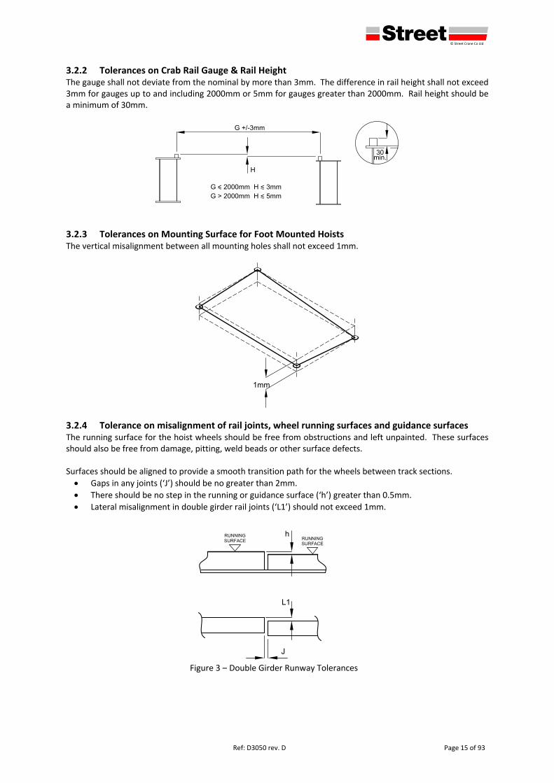
3.2.2 Tolerances on Crab Rail Gauge & Rail Height The gauge shall not deviate from the nominal by more than 3mm. The difference in rail height shall not exceed 3mm for gauges up to and including 2000mm or 5mm for gauges greater than 2000mm. Rail height should be a minimum of 30mm.
3.2.3 Tolerances on Mounting Surface for Foot Mounted Hoists The vertical misalignment between all mounting holes shall not exceed 1mm.
3.2.4 Tolerance on misalignment of rail joints, wheel running surfaces and guidance surfaces The running surface for the hoist wheels should be free from obstructions and left unpainted. These surfaces should also be free from damage, pitting, weld beads or other surface defects. Surfaces should be aligned to provide a smooth transition path for the wheels between track sections.
Gaps in any joints (‘J’) should be no greater than 2mm.
There should be no step in the running or guidance surface (‘h’) greater than 0.5mm.
Lateral misalignment in double girder rail joints (‘L1’) should not exceed 1mm.
Figure 3 – Double Girder Runway Tolerances
defgh © Street Crane Co Ltd
Page 16 of 93 Ref: D3050 rev. D
3.3 HOIST WEIGHTS AND LIFTING POINTS
3.3.1 Foot Mount
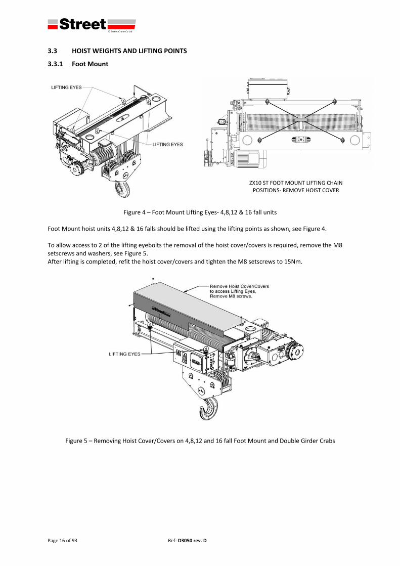
Figure 4 – Foot Mount Lifting Eyes‐ 4,8,12 & 16 fall units Foot Mount hoist units 4,8,12 & 16 falls should be lifted using the lifting points as shown, see Figure 4. To allow access to 2 of the lifting eyebolts the removal of the hoist cover/covers is required, remove the M8 setscrews and washers, see Figure 5. After lifting is completed, refit the hoist cover/covers and tighten the M8 setscrews to 15Nm.
Figure 5 – Removing Hoist Cover/Covers on 4,8,12 and 16 fall Foot Mount and Double Girder Crabs
ZX10 ST FOOT MOUNT LIFTING CHAIN POSITIONS‐ REMOVE HOIST COVER
defgh © Street Crane Co Ltd
Ref: D3050 rev. D Page 17 of 93
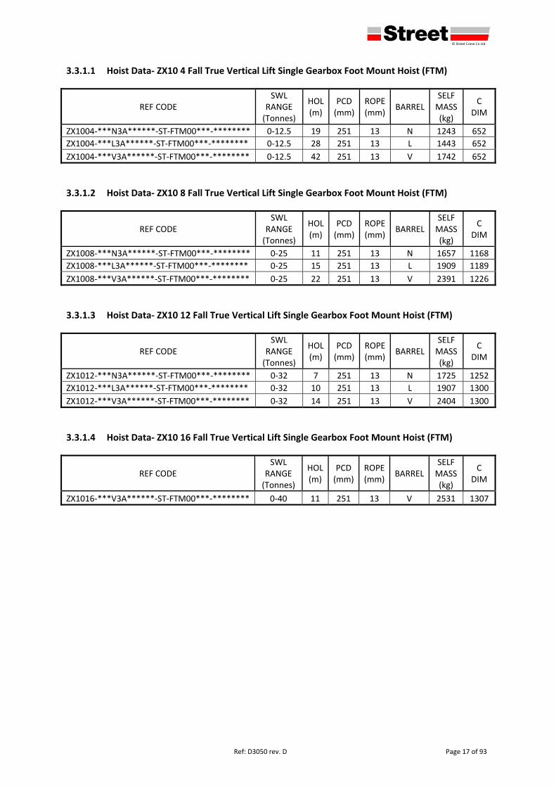
3.3.1.1 Hoist Data‐ ZX10 4 Fall True Vertical Lift Single Gearbox Foot Mount Hoist (FTM)
REF CODE SWL
RANGE (Tonnes)
HOL (m)
PCD (mm)
ROPE (mm)
BARREL SELF MASS (kg)
C DIM
ZX1004‐***N3A******‐ST‐FTM00***‐******** 0‐12.5 19 251 13 N 1243 652
ZX1004‐***L3A******‐ST‐FTM00***‐******** 0‐12.5 28 251 13 L 1443 652
ZX1004‐***V3A******‐ST‐FTM00***‐******** 0‐12.5 42 251 13 V 1742 652
3.3.1.2 Hoist Data‐ ZX10 8 Fall True Vertical Lift Single Gearbox Foot Mount Hoist (FTM)
REF CODE SWL
RANGE (Tonnes)
HOL (m)
PCD (mm)
ROPE (mm)
BARREL SELF MASS (kg)
C DIM
ZX1008‐***N3A******‐ST‐FTM00***‐******** 0‐25 11 251 13 N 1657 1168
ZX1008‐***L3A******‐ST‐FTM00***‐******** 0‐25 15 251 13 L 1909 1189
ZX1008‐***V3A******‐ST‐FTM00***‐******** 0‐25 22 251 13 V 2391 1226
3.3.1.3 Hoist Data‐ ZX10 12 Fall True Vertical Lift Single Gearbox Foot Mount Hoist (FTM)
REF CODE SWL
RANGE (Tonnes)
HOL (m)
PCD (mm)
ROPE (mm)
BARREL SELF MASS (kg)
C DIM
ZX1012‐***N3A******‐ST‐FTM00***‐******** 0‐32 7 251 13 N 1725 1252
ZX1012‐***L3A******‐ST‐FTM00***‐******** 0‐32 10 251 13 L 1907 1300
ZX1012‐***V3A******‐ST‐FTM00***‐******** 0‐32 14 251 13 V 2404 1300
3.3.1.4 Hoist Data‐ ZX10 16 Fall True Vertical Lift Single Gearbox Foot Mount Hoist (FTM)
REF CODE SWL
RANGE (Tonnes)
HOL (m)
PCD (mm)
ROPE (mm)
BARREL SELF MASS (kg)
C DIM
ZX1016‐***V3A******‐ST‐FTM00***‐******** 0‐40 11 251 13 V 2531 1307
defgh © Street Crane Co Ltd
Page 18 of 93 Ref: D3050 rev. D
3.3.2 Double Girder Crab
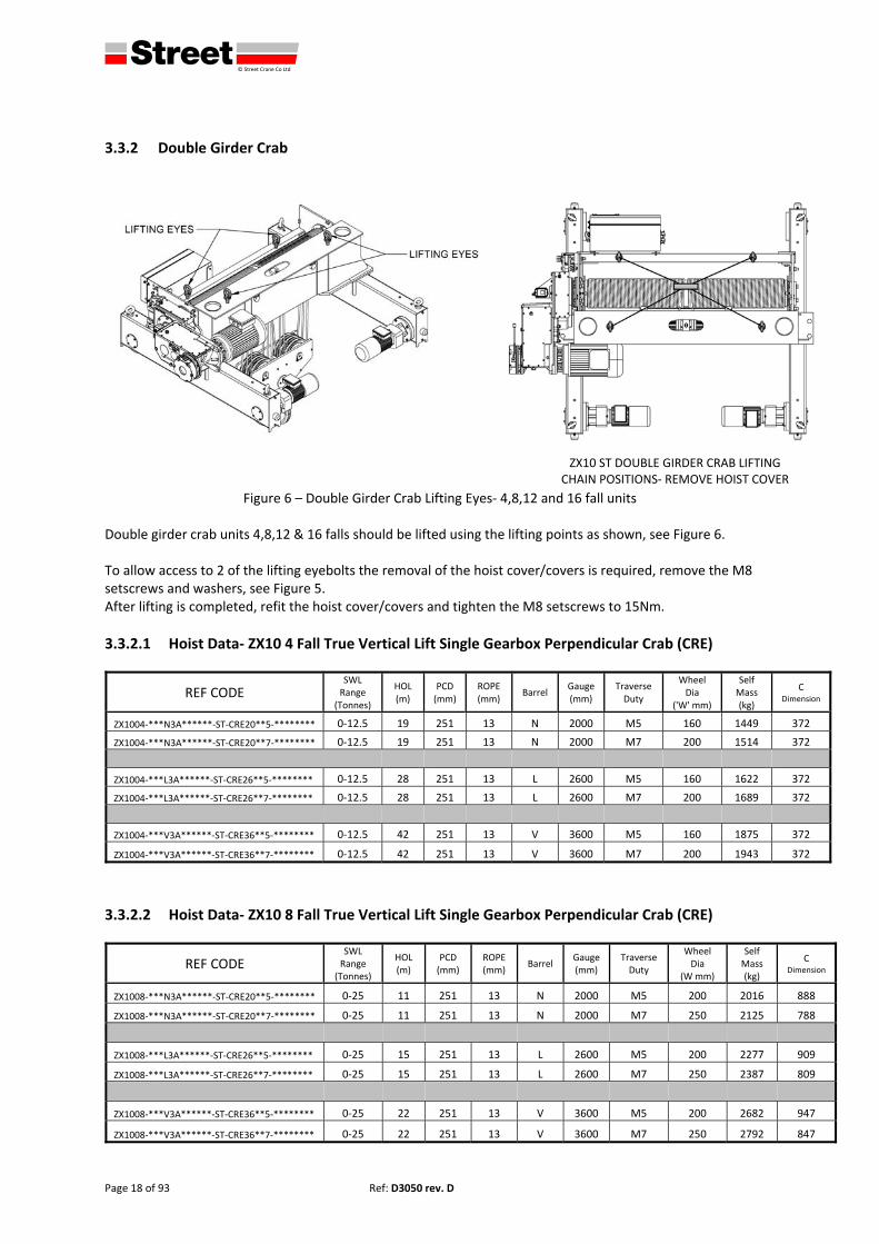
Figure 6 – Double Girder Crab Lifting Eyes‐ 4,8,12 and 16 fall units
Double girder crab units 4,8,12 & 16 falls should be lifted using the lifting points as shown, see Figure 6. To allow access to 2 of the lifting eyebolts the removal of the hoist cover/covers is required, remove the M8 setscrews and washers, see Figure 5. After lifting is completed, refit the hoist cover/covers and tighten the M8 setscrews to 15Nm.
3.3.2.1 Hoist Data‐ ZX10 4 Fall True Vertical Lift Single Gearbox Perpendicular Crab (CRE)
REF CODE SWL Range
(Tonnes)
HOL (m)
PCD (mm)
ROPE (mm)
Barrel Gauge(mm)
Traverse Duty
Wheel Dia
('W' mm)
Self Mass (kg)
C Dimension
ZX1004‐***N3A******‐ST‐CRE20**5‐******** 0‐12.5 19 251 13 N 2000 M5 160 1449 372
ZX1004‐***N3A******‐ST‐CRE20**7‐******** 0‐12.5 19 251 13 N 2000 M7 200 1514 372
ZX1004‐***L3A******‐ST‐CRE26**5‐******** 0‐12.5 28 251 13 L 2600 M5 160 1622 372
ZX1004‐***L3A******‐ST‐CRE26**7‐******** 0‐12.5 28 251 13 L 2600 M7 200 1689 372
ZX1004‐***V3A******‐ST‐CRE36**5‐******** 0‐12.5 42 251 13 V 3600 M5 160 1875 372
ZX1004‐***V3A******‐ST‐CRE36**7‐******** 0‐12.5 42 251 13 V 3600 M7 200 1943 372
3.3.2.2 Hoist Data‐ ZX10 8 Fall True Vertical Lift Single Gearbox Perpendicular Crab (CRE)
REF CODE SWL Range
(Tonnes)
HOL (m)
PCD (mm)
ROPE (mm)
Barrel Gauge(mm)
Traverse Duty
Wheel Dia
(W mm)
Self Mass (kg)
C Dimension
ZX1008‐***N3A******‐ST‐CRE20**5‐******** 0‐25 11 251 13 N 2000 M5 200 2016 888
ZX1008‐***N3A******‐ST‐CRE20**7‐******** 0‐25 11 251 13 N 2000 M7 250 2125 788
ZX1008‐***L3A******‐ST‐CRE26**5‐******** 0‐25 15 251 13 L 2600 M5 200 2277 909
ZX1008‐***L3A******‐ST‐CRE26**7‐******** 0‐25 15 251 13 L 2600 M7 250 2387 809
ZX1008‐***V3A******‐ST‐CRE36**5‐******** 0‐25 22 251 13 V 3600 M5 200 2682 947
ZX1008‐***V3A******‐ST‐CRE36**7‐******** 0‐25 22 251 13 V 3600 M7 250 2792 847
ZX10 ST DOUBLE GIRDER CRAB LIFTING CHAIN POSITIONS‐ REMOVE HOIST COVER
defgh © Street Crane Co Ltd
Ref: D3050 rev. D Page 19 of 93
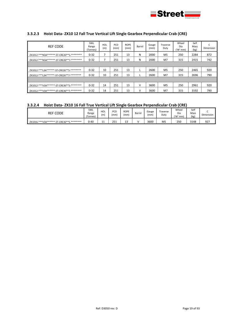
3.3.2.3 Hoist Data‐ ZX10 12 Fall True Vertical Lift Single Gearbox Perpendicular Crab (CRE)
REF CODE SWL Range
(Tonnes)
HOL (m)
PCD (mm)
ROPE (mm)
Barrel Gauge(mm)
Traverse Duty
Wheel Dia
('W' mm)
Self Mass (kg)
C Dimension
ZX1012‐***N3A******‐ST‐CRE20**5‐******** 0‐32 7 251 13 N 2000 M5 250 2284 872
ZX1012‐***N3A******‐ST‐CRE20**7‐******** 0‐32 7 251 13 N 2000 M7 315 2415 742
ZX1012‐***L3A******‐ST‐CRE26**5‐******** 0‐32 10 251 13 L 2600 M5 250 2465 920
ZX1012‐***L3A******‐ST‐CRE26**7‐******** 0‐32 10 251 13 L 2600 M7 315 2696 790
ZX1012‐***V3A******‐ST‐CRE36**5‐******** 0‐32 14 251 13 V 3600 M5 250 2961 920
ZX1012‐***V3A******‐ST‐CRE36**7‐******** 0‐32 14 251 13 V 3600 M7 315 3192 790
3.3.2.4 Hoist Data‐ ZX10 16 Fall True Vertical Lift Single Gearbox Perpendicular Crab (CRE)
REF CODE SWL Range
(Tonnes)
HOL (m)
PCD (mm)
ROPE (mm)
Barrel Gauge (mm)
Traverse Duty
Wheel Dia
('W' mm)
Self Mass (kg)
C Dimension
ZX1016‐***V3A******‐ST‐CRE36**5‐******** 0‐40 11 251 13 V 3600 M5 250 3148 927
defgh © Street Crane Co Ltd
Page 20 of 93 Ref: D3050 rev. D
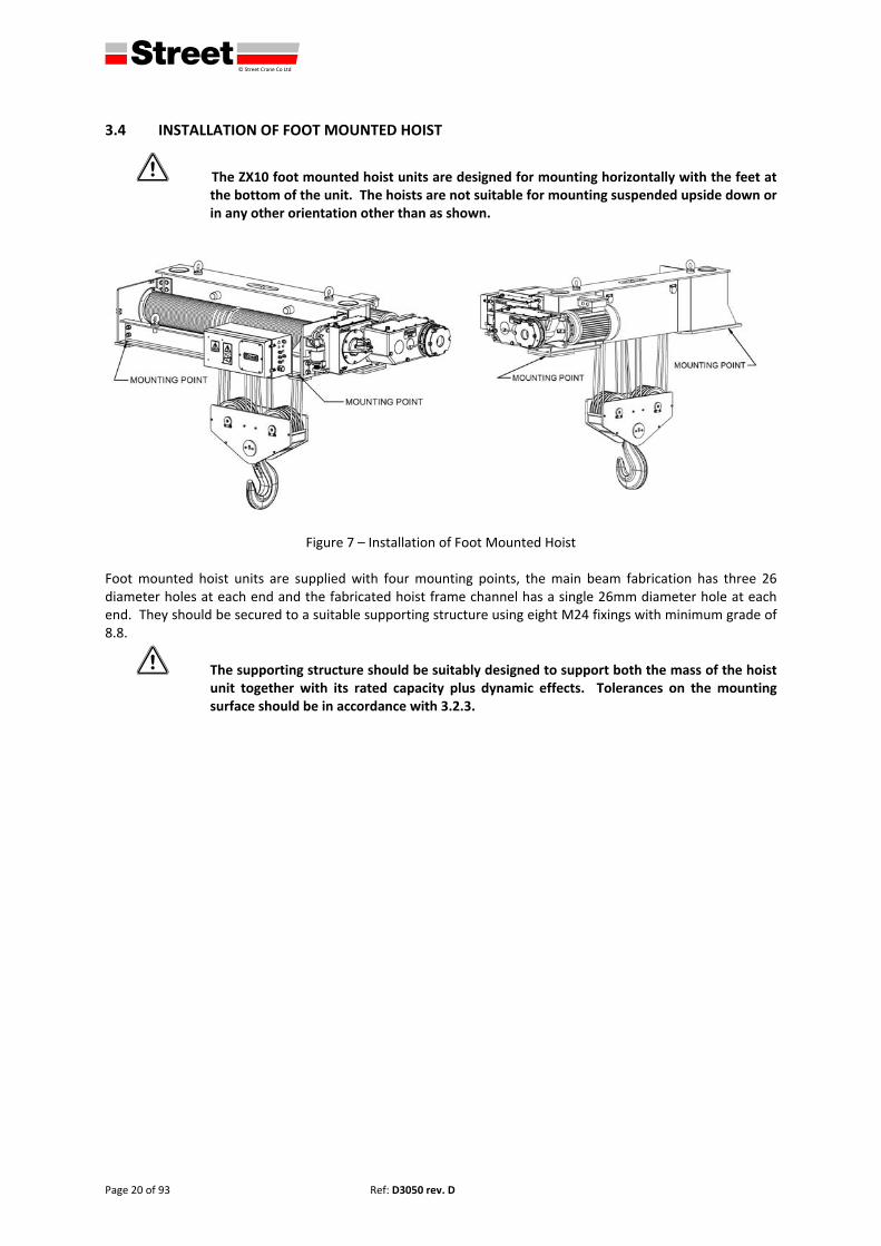
3.4 INSTALLATION OF FOOT MOUNTED HOIST
1 The ZX10 foot mounted hoist units are designed for mounting horizontally with the feet at the bottom of the unit. The hoists are not suitable for mounting suspended upside down or in any other orientation other than as shown.
Figure 7 – Installation of Foot Mounted Hoist
Foot mounted hoist units are supplied with four mounting points, the main beam fabrication has three 26 diameter holes at each end and the fabricated hoist frame channel has a single 26mm diameter hole at each end. They should be secured to a suitable supporting structure using eight M24 fixings with minimum grade of 8.8.
1 The supporting structure should be suitably designed to support both the mass of the hoist unit together with its rated capacity plus dynamic effects. Tolerances on the mounting surface should be in accordance with 3.2.3.
defgh © Street Crane Co Ltd
Ref: D3050 rev. D Page 21 of 93
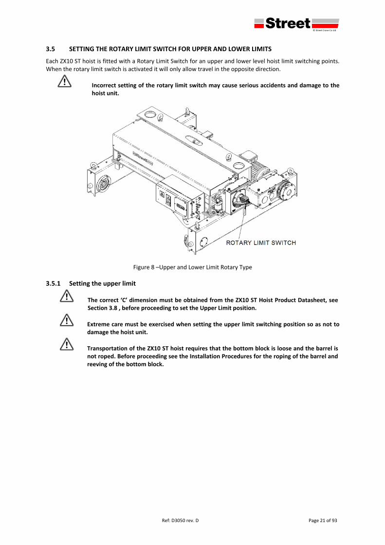
3.5 SETTING THE ROTARY LIMIT SWITCH FOR UPPER AND LOWER LIMITS
Each ZX10 ST hoist is fitted with a Rotary Limit Switch for an upper and lower level hoist limit switching points. When the rotary limit switch is activated it will only allow travel in the opposite direction.
1 Incorrect setting of the rotary limit switch may cause serious accidents and damage to the hoist unit.
Figure 8 –Upper and Lower Limit Rotary Type
3.5.1 Setting the upper limit
1 The correct ‘C’ dimension must be obtained from the ZX10 ST Hoist Product Datasheet, see Section 3.8 , before proceeding to set the Upper Limit position.
1 Extreme care must be exercised when setting the upper limit switching position so as not to damage the hoist unit.
1 Transportation of the ZX10 ST hoist requires that the bottom block is loose and the barrel is not roped. Before proceeding see the Installation Procedures for the roping of the barrel and reeving of the bottom block.
defgh © Street Crane Co Ltd
Page 22 of 93 Ref: D3050 rev. D
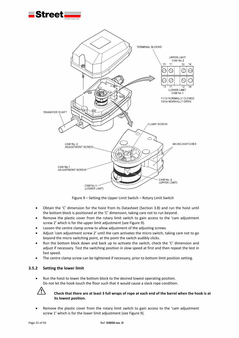
Figure 9 – Setting the Upper Limit Switch – Rotary Limit Switch
Obtain the ‘C’ dimension for the hoist from its Datasheet (Section 3.8) and run the hoist until the bottom block is positioned at the ‘C’ dimension, taking care not to run beyond.
Remove the plastic cover from the rotary limit switch to gain access to the ‘cam adjustment screw 2’ which is for the upper limit adjustment (see Figure 9).
Loosen the centre clamp screw to allow adjustment of the adjusting screws.
Adjust ‘cam adjustment screw 2’ until the cam activates the micro switch, taking care not to go beyond the micro switching point, at the point the switch audibly clicks.
Run the bottom block down and back up to activate the switch, check the ‘C’ dimension and adjust if necessary. Test the switching position in slow speed at first and then repeat the test in fast speed.
The centre clamp screw can be tightened if necessary, prior to bottom limit position setting.
3.5.2 Setting the lower limit
Run the hoist to lower the bottom block to the desired lowest operating position. Do not let the hook touch the floor such that it would cause a slack rope condition.
1 Check that there are at least 3 full wraps of rope at each end of the barrel when the hook is at its lowest position.
Remove the plastic cover from the rotary limit switch to gain access to the ‘cam adjustment screw 1’ which is for the lower limit adjustment (see Figure 9).
defgh © Street Crane Co Ltd
Ref: D3050 rev. D Page 23 of 93
Loosen the centre clamp screw to allow adjustment of the adjusting screws.
Adjust ‘cam adjustment screw 1’ until the cam activates the micro switch, taking care not to go beyond the micro switching point, at the point the switch audibly clicks.
Run the bottom block up and back down to activate the switch, check the position of the bottom block/hook and adjust if necessary. Test the switching position in slow speed at first and then repeat the test in fast speed.
The centre clamp screw can now be tightened to set both the lower and upper limit switching points.
Refit the plastic cover securing with 2 x screws.
defgh © Street Crane Co Ltd
Page 24 of 93 Ref: D3050 rev. D
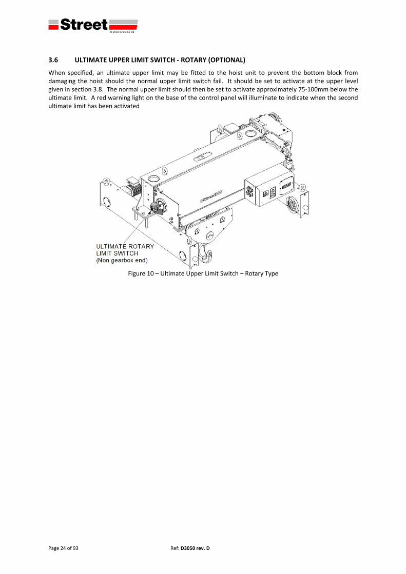
3.6 ULTIMATE UPPER LIMIT SWITCH ‐ ROTARY (OPTIONAL)
When specified, an ultimate upper limit may be fitted to the hoist unit to prevent the bottom block from damaging the hoist should the normal upper limit switch fail. It should be set to activate at the upper level given in section 3.8. The normal upper limit should then be set to activate approximately 75‐100mm below the ultimate limit. A red warning light on the base of the control panel will illuminate to indicate when the second ultimate limit has been activated
Figure 10 – Ultimate Upper Limit Switch – Rotary Type
defgh © Street Crane Co Ltd
Ref: D3050 rev. D Page 25 of 93
3.6.1 Setting the ultimate upper limit‐ ROTARY (OPTIONAL)
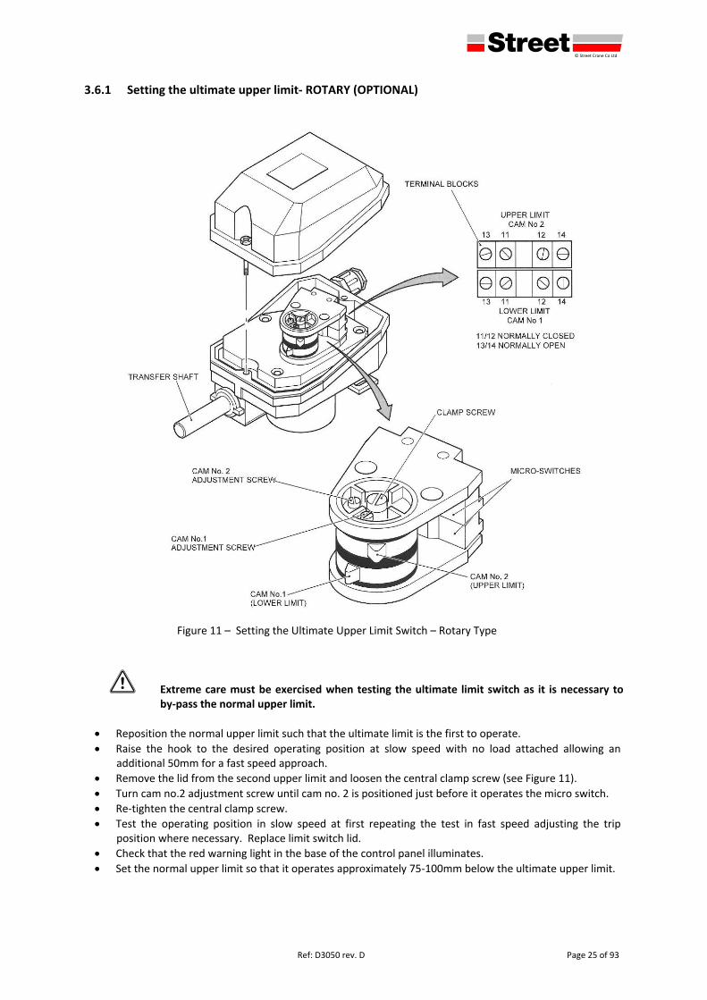
Figure 11 – Setting the Ultimate Upper Limit Switch – Rotary Type
1 Extreme care must be exercised when testing the ultimate limit switch as it is necessary to by‐pass the normal upper limit.
Reposition the normal upper limit such that the ultimate limit is the first to operate.
Raise the hook to the desired operating position at slow speed with no load attached allowing an additional 50mm for a fast speed approach.
Remove the lid from the second upper limit and loosen the central clamp screw (see Figure 11).
Turn cam no.2 adjustment screw until cam no. 2 is positioned just before it operates the micro switch.
Re‐tighten the central clamp screw.
Test the operating position in slow speed at first repeating the test in fast speed adjusting the trip position where necessary. Replace limit switch lid.
Check that the red warning light in the base of the control panel illuminates.
Set the normal upper limit so that it operates approximately 75‐100mm below the ultimate upper limit.
defgh © Street Crane Co Ltd
Page 26 of 93 Ref: D3050 rev. D
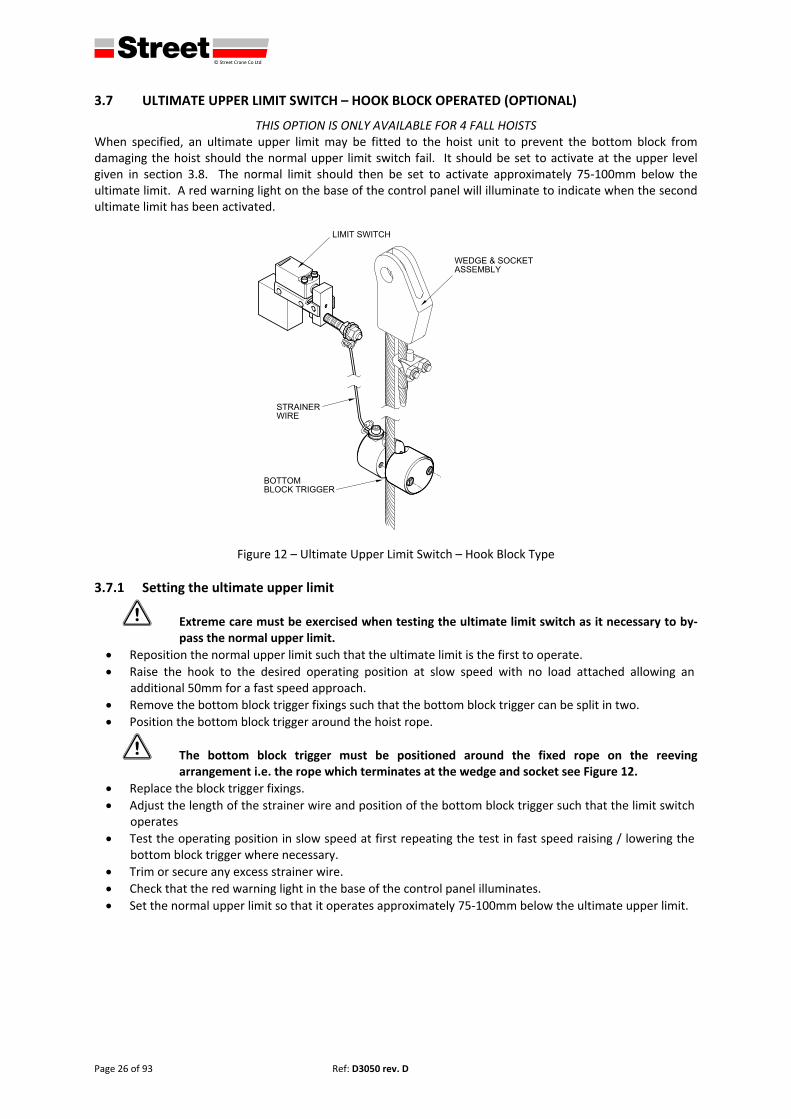
3.7 ULTIMATE UPPER LIMIT SWITCH – HOOK BLOCK OPERATED (OPTIONAL)
THIS OPTION IS ONLY AVAILABLE FOR 4 FALL HOISTS When specified, an ultimate upper limit may be fitted to the hoist unit to prevent the bottom block from damaging the hoist should the normal upper limit switch fail. It should be set to activate at the upper level given in section 3.8. The normal limit should then be set to activate approximately 75‐100mm below the ultimate limit. A red warning light on the base of the control panel will illuminate to indicate when the second ultimate limit has been activated.
Figure 12 – Ultimate Upper Limit Switch – Hook Block Type
3.7.1 Setting the ultimate upper limit
1 Extreme care must be exercised when testing the ultimate limit switch as it necessary to by‐pass the normal upper limit.
Reposition the normal upper limit such that the ultimate limit is the first to operate.
Raise the hook to the desired operating position at slow speed with no load attached allowing an additional 50mm for a fast speed approach.
Remove the bottom block trigger fixings such that the bottom block trigger can be split in two.
Position the bottom block trigger around the hoist rope.
1 The bottom block trigger must be positioned around the fixed rope on the reeving arrangement i.e. the rope which terminates at the wedge and socket see Figure 12.
Replace the block trigger fixings.
Adjust the length of the strainer wire and position of the bottom block trigger such that the limit switch operates
Test the operating position in slow speed at first repeating the test in fast speed raising / lowering the bottom block trigger where necessary.
Trim or secure any excess strainer wire.
Check that the red warning light in the base of the control panel illuminates.
Set the normal upper limit so that it operates approximately 75‐100mm below the ultimate upper limit.
defgh © Street Crane Co Ltd
Ref: D3050 rev. D Page 27 of 93
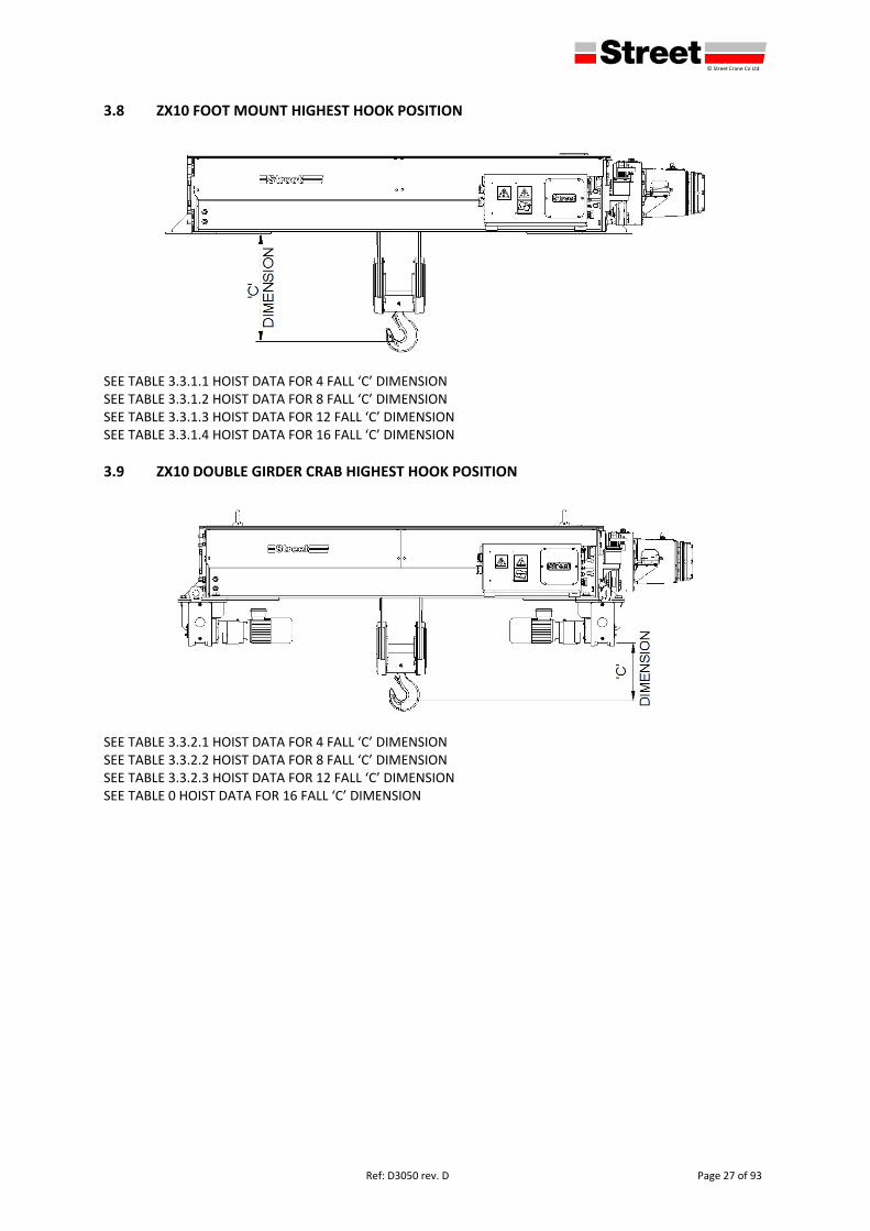
3.8 ZX10 FOOT MOUNT HIGHEST HOOK POSITION
SEE TABLE 3.3.1.1 HOIST DATA FOR 4 FALL ‘C’ DIMENSION SEE TABLE 3.3.1.2 HOIST DATA FOR 8 FALL ‘C’ DIMENSION SEE TABLE 3.3.1.3 HOIST DATA FOR 12 FALL ‘C’ DIMENSION SEE TABLE 3.3.1.4 HOIST DATA FOR 16 FALL ‘C’ DIMENSION
3.9 ZX10 DOUBLE GIRDER CRAB HIGHEST HOOK POSITION
SEE TABLE 3.3.2.1 HOIST DATA FOR 4 FALL ‘C’ DIMENSION SEE TABLE 3.3.2.2 HOIST DATA FOR 8 FALL ‘C’ DIMENSION SEE TABLE 3.3.2.3 HOIST DATA FOR 12 FALL ‘C’ DIMENSION SEE TABLE 0 HOIST DATA FOR 16 FALL ‘C’ DIMENSION
defgh © Street Crane Co Ltd
Page 28 of 93 Ref: D3050 rev. D
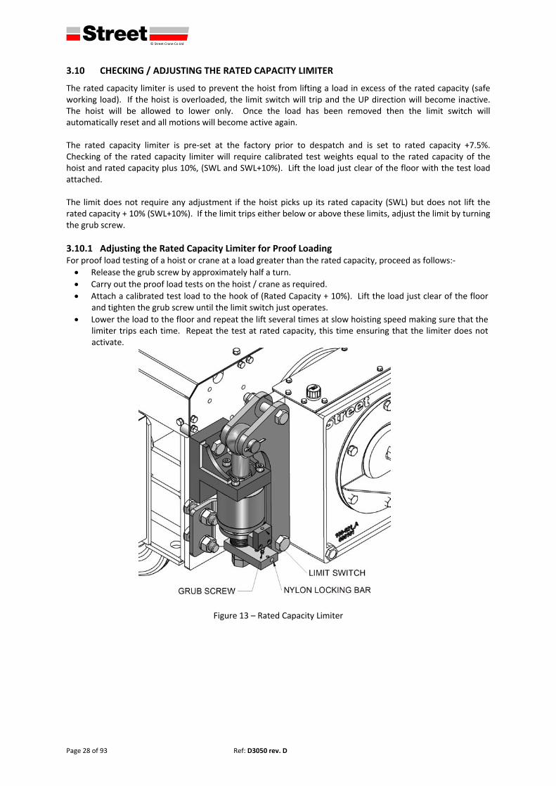
3.10 CHECKING / ADJUSTING THE RATED CAPACITY LIMITER
The rated capacity limiter is used to prevent the hoist from lifting a load in excess of the rated capacity (safe working load). If the hoist is overloaded, the limit switch will trip and the UP direction will become inactive. The hoist will be allowed to lower only. Once the load has been removed then the limit switch will automatically reset and all motions will become active again. The rated capacity limiter is pre‐set at the factory prior to despatch and is set to rated capacity +7.5%. Checking of the rated capacity limiter will require calibrated test weights equal to the rated capacity of the hoist and rated capacity plus 10%, (SWL and SWL+10%). Lift the load just clear of the floor with the test load attached. The limit does not require any adjustment if the hoist picks up its rated capacity (SWL) but does not lift the rated capacity + 10% (SWL+10%). If the limit trips either below or above these limits, adjust the limit by turning the grub screw.
3.10.1 Adjusting the Rated Capacity Limiter for Proof Loading For proof load testing of a hoist or crane at a load greater than the rated capacity, proceed as follows:‐
Release the grub screw by approximately half a turn.
Carry out the proof load tests on the hoist / crane as required.
Attach a calibrated test load to the hook of (Rated Capacity + 10%). Lift the load just clear of the floor and tighten the grub screw until the limit switch just operates.
Lower the load to the floor and repeat the lift several times at slow hoisting speed making sure that the limiter trips each time. Repeat the test at rated capacity, this time ensuring that the limiter does not activate.
Figure 13 – Rated Capacity Limiter
defgh © Street Crane Co Ltd
Ref: D3050 rev. D Page 29 of 93
3.11 TRAVERSE LIMITS (OPTIONAL)
The traverse limit arrangement employs either a one or two stage cruciform switch depending on the type of stopping arrangement. Be sure of the type that is fitted to your hoist.
A single stage limit switch (type PF33710100) is employed to stop the motion completely when the limit is reached or to allow the hoist to proceed at slow speed only until the end stop is reached. The single stage limit employs one actuating arm at each end of travel.
The two stage switch (type PF26755100) is employed to firstly slow the speed from fast to slow and then to stop the motion completely on reaching the second stage. The two stage limit employs two actuating arms at each end of travel.
NOTE: On each of the above, when the limit is tripped, normal operation is available in the opposite direction. Reversing away from the stop is at the speed selected by the operator (slow or fast).
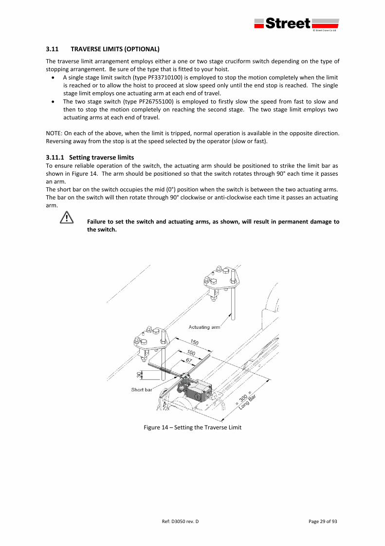
3.11.1 Setting traverse limits To ensure reliable operation of the switch, the actuating arm should be positioned to strike the limit bar as shown in Figure 14. The arm should be positioned so that the switch rotates through 90° each time it passes an arm. The short bar on the switch occupies the mid (0°) position when the switch is between the two actuating arms. The bar on the switch will then rotate through 90° clockwise or anti‐clockwise each time it passes an actuating arm.
1 Failure to set the switch and actuating arms, as shown, will result in permanent damage to the switch.
Figure 14 – Setting the Traverse Limit
defgh © Street Crane Co Ltd
Page 30 of 93 Ref: D3050 rev. D
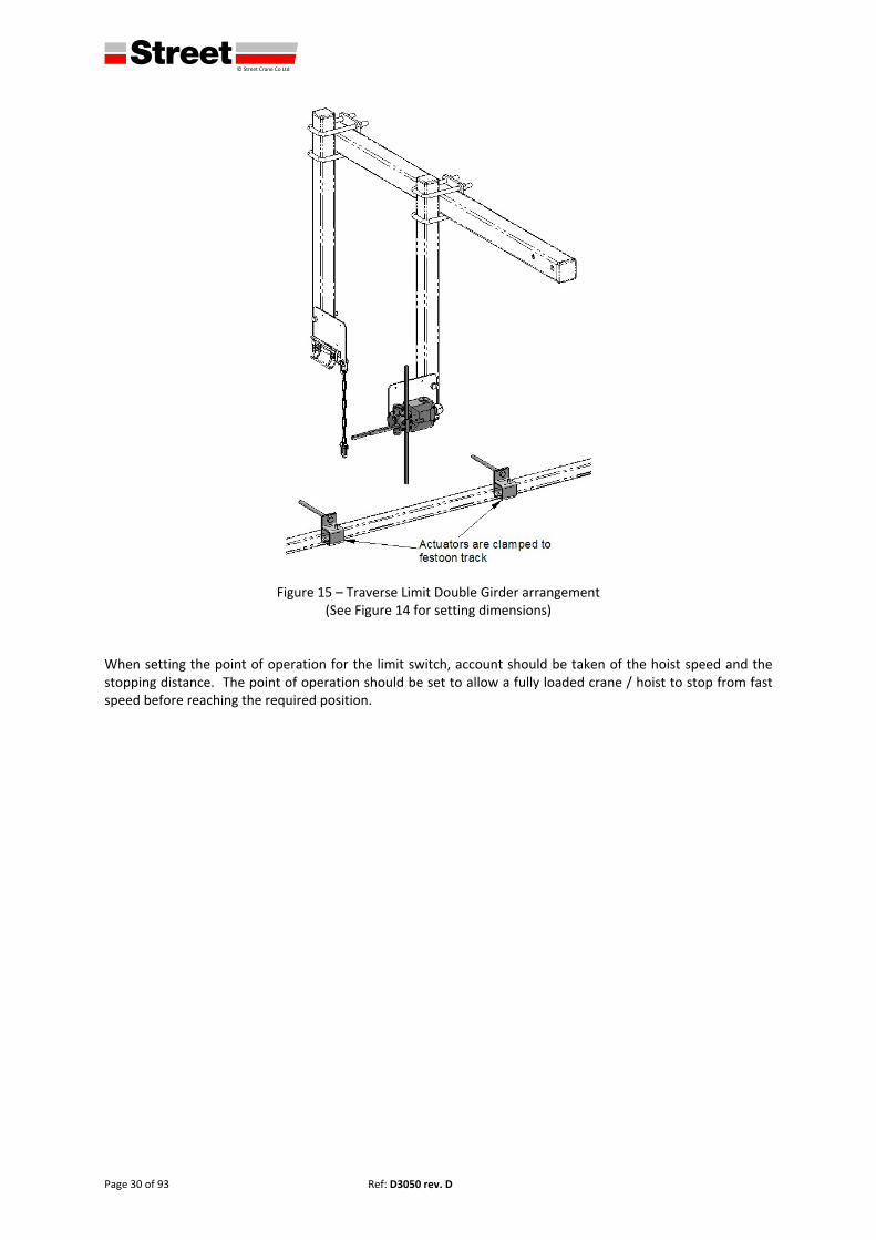
Figure 15 – Traverse Limit Double Girder arrangement (See Figure 14 for setting dimensions)
When setting the point of operation for the limit switch, account should be taken of the hoist speed and the stopping distance. The point of operation should be set to allow a fully loaded crane / hoist to stop from fast speed before reaching the required position.
defgh © Street Crane Co Ltd
Ref: D3050 rev. D Page 31 of 93
3.12 CONNECTING THE POWER SUPPLY
1 Connection of the power supply must be carried out by a competent person. Ensure that the supply to the hoist matches the information in the hoist technical data and on the hoist nameplate. Also ensure that the supply has been correctly installed and protected, i.e. voltage, phase, frequency, fuse size, cable/conductor size. Check that the voltage at the point of supply is within the tolerance of ±5% and the nominal frequency is within the tolerance of ±1% of the rated values.
3.12.1 Supply cables / fuses The size of the supply cables to the hoist must be selected in accordance with the table in section 7.6. Terminals must be of a size appropriate to the cable size and securely fixed. Selection of a suitable size of mains fuse is given in section 7.5. Fuses of class gL/gG should be used (or type ‘J’ for CSA installations).
3.12.2 Main isolator – supply switch (by others) The main isolator (supply switch) must disconnect all phases of the supply to the hoist, must be clearly marked and located in an easily accessible position. The switch should be capable of being locked in the OFF position whilst any maintenance work is being carried out. The main isolator, if reasonably accessible, may also be used for emergency stop or emergency off purposes. NOTE a separate emergency stop is located on the hoist controller see 4.4.5.
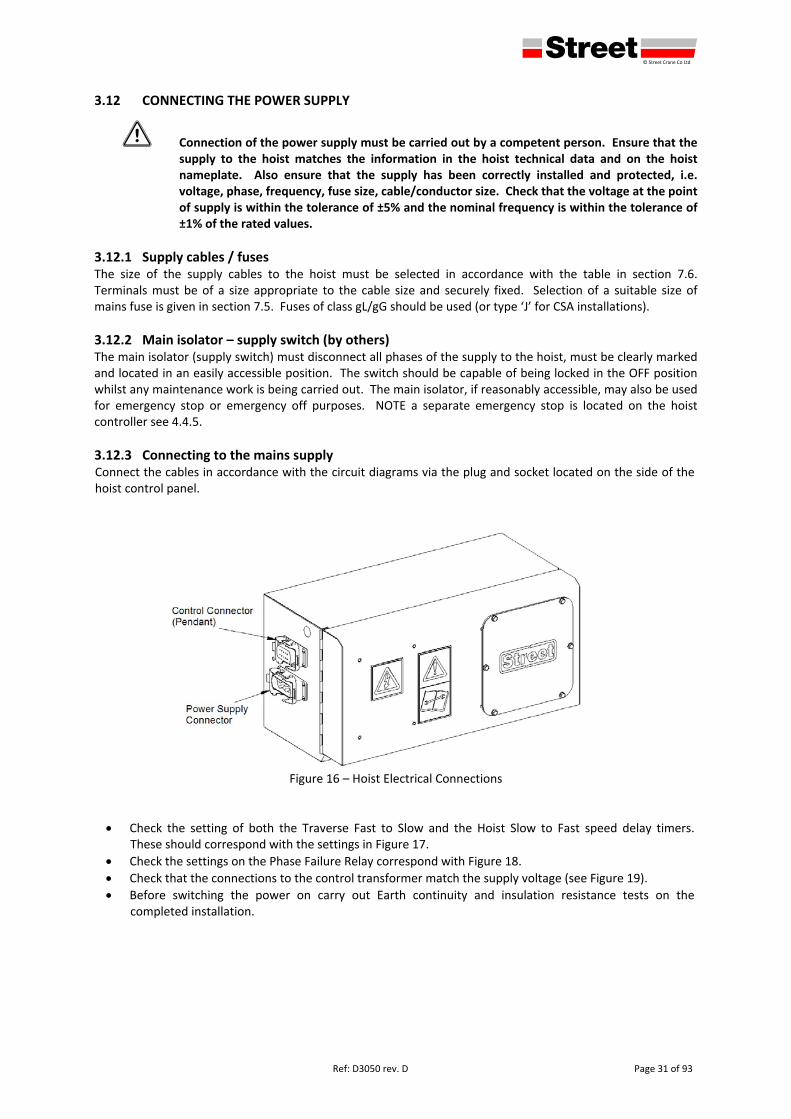
3.12.3 Connecting to the mains supply Connect the cables in accordance with the circuit diagrams via the plug and socket located on the side of the hoist control panel.
Figure 16 – Hoist Electrical Connections
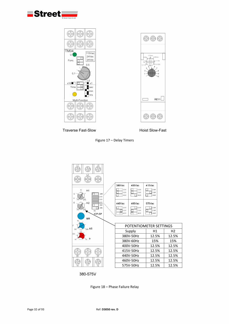
Check the setting of both the Traverse Fast to Slow and the Hoist Slow to Fast speed delay timers. These should correspond with the settings in Figure 17.
Check the settings on the Phase Failure Relay correspond with Figure 18.
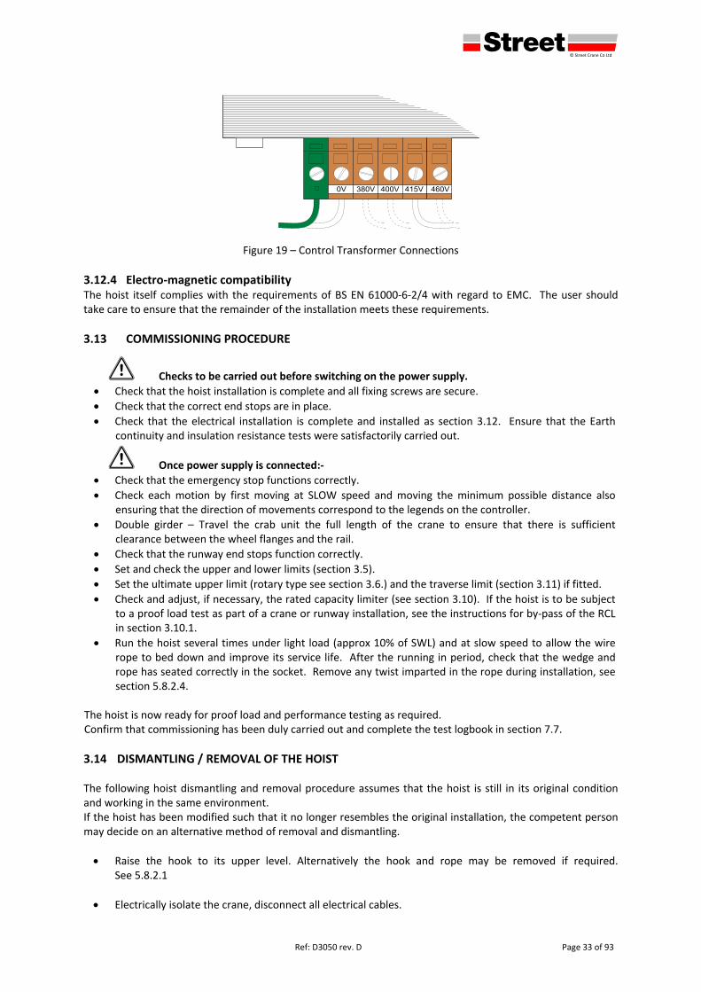
Check that the connections to the control transformer match the supply voltage (see Figure 19).
Before switching the power on carry out Earth continuity and insulation resistance tests on the completed installation.
defgh © Street Crane Co Ltd
Page 32 of 93 Ref: D3050 rev. D
Figure 17 – Delay Timers
Figure 18 – Phase Failure Relay
POTENTIOMETER SETTINGS Supply H1 H2
380V‐50Hz 12.5% 12.5%
380V‐60Hz 15% 15%
400V‐50Hz 12.5% 12.5%
415V‐50Hz 12.5% 12.5%
440V‐50Hz 12.5% 12.5%
460V‐50Hz 12.5% 12.5%
575V‐50Hz 12.5% 12.5%
defgh © Street Crane Co Ltd
Ref: D3050 rev. D Page 33 of 93
Figure 19 – Control Transformer Connections
3.12.4 Electro‐magnetic compatibility The hoist itself complies with the requirements of BS EN 61000‐6‐2/4 with regard to EMC. The user should take care to ensure that the remainder of the installation meets these requirements.
3.13 COMMISSIONING PROCEDURE
1 Checks to be carried out before switching on the power supply.
Check that the hoist installation is complete and all fixing screws are secure.
Check that the correct end stops are in place.
Check that the electrical installation is complete and installed as section 3.12. Ensure that the Earth continuity and insulation resistance tests were satisfactorily carried out.
1 Once power supply is connected:‐
Check that the emergency stop functions correctly.
Check each motion by first moving at SLOW speed and moving the minimum possible distance also ensuring that the direction of movements correspond to the legends on the controller.
Double girder – Travel the crab unit the full length of the crane to ensure that there is sufficient clearance between the wheel flanges and the rail.
Check that the runway end stops function correctly.
Set and check the upper and lower limits (section 3.5).
Set the ultimate upper limit (rotary type see section 3.6.) and the traverse limit (section 3.11) if fitted.
Check and adjust, if necessary, the rated capacity limiter (see section 3.10). If the hoist is to be subject to a proof load test as part of a crane or runway installation, see the instructions for by‐pass of the RCL in section 3.10.1.
Run the hoist several times under light load (approx 10% of SWL) and at slow speed to allow the wire rope to bed down and improve its service life. After the running in period, check that the wedge and rope has seated correctly in the socket. Remove any twist imparted in the rope during installation, see section 5.8.2.4.
The hoist is now ready for proof load and performance testing as required. Confirm that commissioning has been duly carried out and complete the test logbook in section 7.7.
3.14 DISMANTLING / REMOVAL OF THE HOIST The following hoist dismantling and removal procedure assumes that the hoist is still in its original condition and working in the same environment. If the hoist has been modified such that it no longer resembles the original installation, the competent person may decide on an alternative method of removal and dismantling.
Raise the hook to its upper level. Alternatively the hook and rope may be removed if required. See 5.8.2.1
Electrically isolate the crane, disconnect all electrical cables.

defgh © Street Crane Co Ltd
Page 34 of 93 Ref: D3050 Rev D
Remove any attachments such as limit brackets, cable towing arms, pendant etc.
Support the weight of the hoist at its appropriate lifting points. See 3.3
Double Girder Crabs can be lowered to the ground.
For Foot Mounted Hoists remove the foot bolts and check there is no adhesion of the foot plates before lowering to the ground.
If the hoist is not to be re‐used, dispose of in an environmentally friendly manner.
defgh © Street Crane Co Ltd
Ref: D3050 rev. D Page 35 of 93
4 OPERATING INSTRUCTIONS
4.1 INTENDED USE
The crane / hoist is designed for lifting, moving and lowering loads, up to the rated capacity of the equipment, by means of a hook or other similar load handling device. The equipment should not be modified or any additions made without the approval of Street Crane Co Ltd.
The equipment is not intended for transporting any persons either suspended in a basket from the hoist or for persons travelling on the crane bridge.
The crane / hoist is not intended for pulling loads at an angle and not for towing or dragging loads along the floor. The hoist is designed for lifting a load in a vertical path only.
Ensure that the hoist is always operated within its rated capacity (SWL). The weight of any lifting gear should be taken into account when assessing the load on the hoist. It may also be necessary to allow for any adhesion between the load and its supports.
1 Overloading can lead to a possible failure of some of the load carrying parts. Overloading the crane / hoist may start a defect, which could lead to future failure even at less than the rated capacity.
Do not use the crane / hoist for pulling loads loose, i.e. pulling components from moulds and always make necessary allowances for any adhesion between the load and its supports.
The end of travel limits, (hoist or travel), are not intended to be a regular method of stopping the motion. They are safety devices and they should be approached with caution.
The hoist is not intended to operate with a slack rope.
4.2 DUTIES OF THE OPERATOR / SAFE HOISTING PRACTICES
At the start of each working day or shift, carry out the daily pre‐use checks see section 5.4. Do not work with any crane or hoist if any defects are found which may compromise safety. The following information serves as a guide for safe hoisting practices and an operator adhering to these will quickly find that he / she is able to work both smoothly and quickly, without prejudicing safety and equipment.
1. Know where the safety, fire and first aid equipment is located and how to use it. 2. Ensure that no one is working on the crane track, crane platform (if fitted) or where they could be
struck by the crane / hoist. 3. Before using the crane / hoist make a full visual inspection to ascertain that the equipment is in
good working order, paying particular attention to the rope and hook. See 5.4 Daily pre‐use inspections.
4. Do not use the crane for anything other than its intended purpose. 5. Ensure the crane is properly maintained and that all the necessary examination and maintenance
records are up to date. 6. All relevant accident prevention, safe lifting and slinging procedures should be obeyed. 7. Constantly monitor all crane and hoist movements and be ready to activate the emergency stop
should any abnormal circumstances arise. Be especially aware of instances where the crane / hoist may fail to stop when the push button/joystick is released or if the crane / hoist moves unexpectedly.
8. Always operate the crane with care and consideration. Care should be taken to avoid the swinging of loads.
9. Ensure that the SWL data plates are clearly visible to the operator at all times. 10. Centre the hoist over the load before lifting. Do not side pull as this can damage the hoist and
endanger the operator. 11. Do not lower the hook / bottom block so far as to allow the hoist ropes to become slack.
1 If this does happen, the operator should satisfy himself that the rope is correctly reeved on the system of sheaves & hoist barrel before continuing to operate the crane.
12. Do not lift a load unless you can see it is securely slung with “suitable” lifting tackle.
defgh © Street Crane Co Ltd
Page 36 of 93 Ref: D3050 Rev D
1 Lifting tackle should only be deemed “suitable” if in accordance with LOLER 98. (Other national regulations may apply).
13. Always gently ‘inch’ the hoist into the load.
1 Running into the load at full hoist speed imposes excessive overloads on the hoist and could result in failure of parts and/or supporting structure.
14. Do not ‘inch’ the hoist unnecessarily. Excessive stopping and starting causes high temperatures in
the motor and brake and may result in overheating or burnout of the component if continued to excess.
15. Do not try and move in the opposite direction until the crane/ hoist has come to a complete stop.
3 Do not stand below a suspended load or allow any other personnel to do so.
16. Prior to operating the travel or traverse motion, the operator should make personnel aware of approaching loads using audible warnings where necessary.
3 Do not move the loads over the heads of other personnel.
17. Do not run the hoist or crane into the travel stops at full speed. Ensure that the rubber buffer is in place and not damaged.
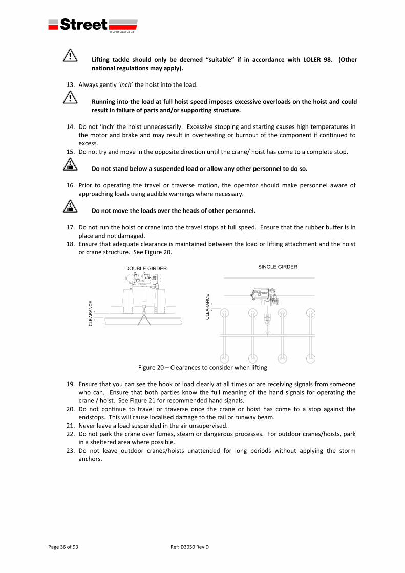
18. Ensure that adequate clearance is maintained between the load or lifting attachment and the hoist or crane structure. See Figure 20.
Figure 20 – Clearances to consider when lifting
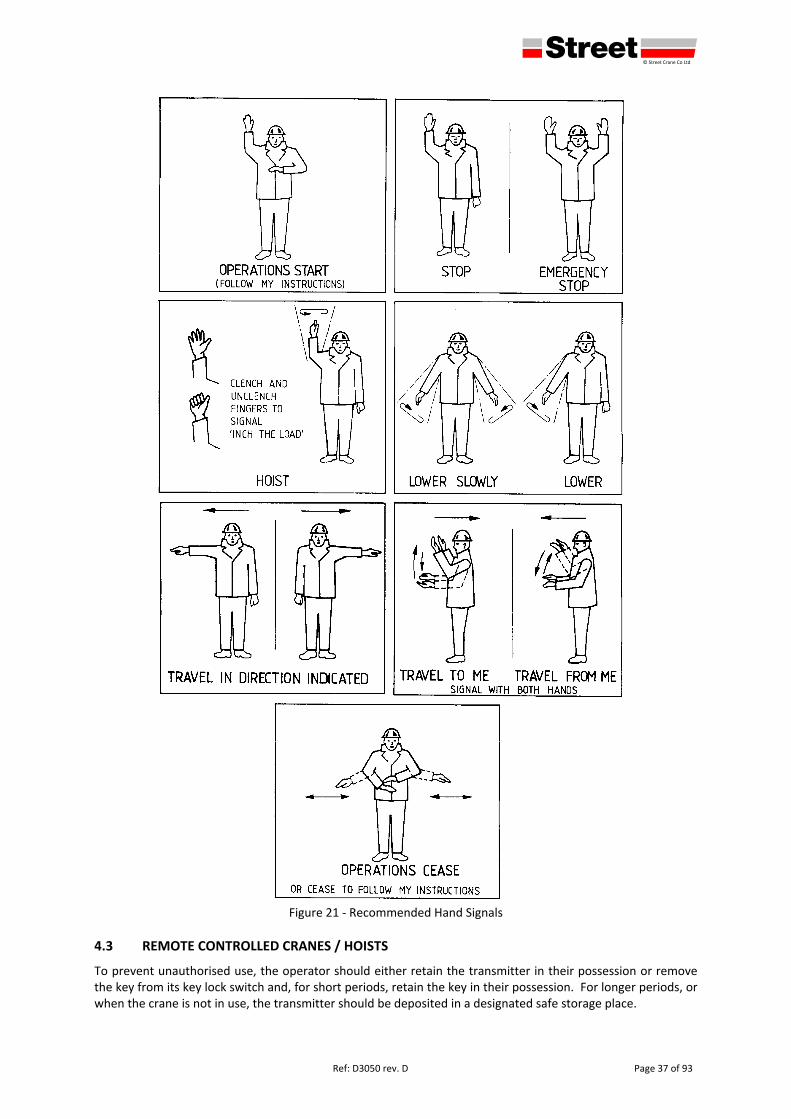
19. Ensure that you can see the hook or load clearly at all times or are receiving signals from someone
who can. Ensure that both parties know the full meaning of the hand signals for operating the crane / hoist. See Figure 21 for recommended hand signals.
20. Do not continue to travel or traverse once the crane or hoist has come to a stop against the endstops. This will cause localised damage to the rail or runway beam.
21. Never leave a load suspended in the air unsupervised. 22. Do not park the crane over fumes, steam or dangerous processes. For outdoor cranes/hoists, park
in a sheltered area where possible. 23. Do not leave outdoor cranes/hoists unattended for long periods without applying the storm
anchors.
defgh © Street Crane Co Ltd
Ref: D3050 rev. D Page 37 of 93
Figure 21 ‐ Recommended Hand Signals
4.3 REMOTE CONTROLLED CRANES / HOISTS
To prevent unauthorised use, the operator should either retain the transmitter in their possession or remove the key from its key lock switch and, for short periods, retain the key in their possession. For longer periods, or when the crane is not in use, the transmitter should be deposited in a designated safe storage place.
defgh © Street Crane Co Ltd
Page 38 of 93 Ref: D3050 Rev D
When the transmitter is fitted with a belt or harness, the operator should be wearing the harness before switching the transmitter on. This will prevent accidental operation of the crane / hoist whilst fitting. The transmitter should also be switched off before removing the harness. Ensure that the identification tag on the radio security key matches the identification number on the radio transmitter and the identification number on the crane.
4.4 CONTROL STATION OPERATING INSTRUCTIONS
The control station may be fitted with either push buttons or joysticks. Pendants will be push button operated, remote control stations may be either push button or joystick. In all cases the push button or joystick is spring applied, which, when released, will return to the neutral position, the motion will stop and the relevant brake will automatically apply.
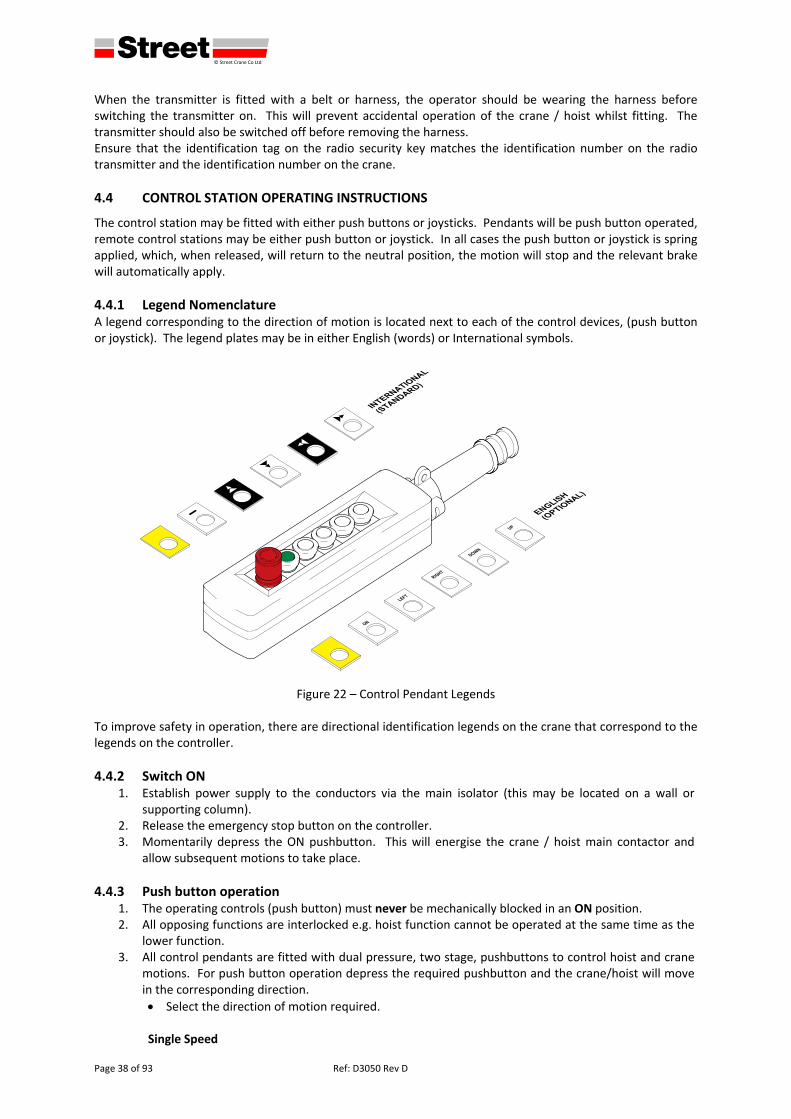
4.4.1 Legend Nomenclature A legend corresponding to the direction of motion is located next to each of the control devices, (push button or joystick). The legend plates may be in either English (words) or International symbols.
Figure 22 – Control Pendant Legends
To improve safety in operation, there are directional identification legends on the crane that correspond to the legends on the controller.
4.4.2 Switch ON 1. Establish power supply to the conductors via the main isolator (this may be located on a wall or
supporting column). 2. Release the emergency stop button on the controller. 3. Momentarily depress the ON pushbutton. This will energise the crane / hoist main contactor and
allow subsequent motions to take place.
4.4.3 Push button operation 1. The operating controls (push button) must never be mechanically blocked in an ON position. 2. All opposing functions are interlocked e.g. hoist function cannot be operated at the same time as the
lower function. 3. All control pendants are fitted with dual pressure, two stage, pushbuttons to control hoist and crane
motions. For push button operation depress the required pushbutton and the crane/hoist will move in the corresponding direction.
Select the direction of motion required. Single Speed
defgh © Street Crane Co Ltd
Ref: D3050 rev. D Page 39 of 93
Press the button to either the first or second pressure. Dual Speed motion (Switchgear Control)
Slow Speed: Press the button in to the first stage.
Fast Speed: Press the button fully in (i.e. to the second stage).
Change Speed ‐ Slow to Fast: To change from slow speed to fast speed push the pushbutton fully in to the second stage.
Change Speed ‐ Fast to Slow (Long travel/traverse motion): To change from fast speed to slow speed, reduce pressure on push button and allow it to come out to the first stage. The motion will first stop and then continue at slow speed.
Change Speed ‐ Fast to Slow (Hoist motion): To change from fast speed to slow speed, release pressure on push button completely and then engage slow speed. The motion will first stop and then continue at slow speed.
Dual Speed motion (Inverter Control – Standard Dual Speed)
Slow Speed: Press the button in to the first stage.
Fast Speed: Press the button fully in (i.e. to the second stage).
Change Speed ‐ Slow to Fast: To change from slow speed to fast speed push the pushbutton fully in to the second stage. The motion will accelerate until it reaches maximum speed.
Change Speed ‐ Fast to Slow: To change from fast speed to slow speed, reduce pressure on push button and allow it to come out to the first stage. The motion will decelerate to slow speed.
Variable Speed (Inverter Control – 2 Stage Ramp and Hold)
Slow Speed: Whilst the motion is stopped, press the button in to the first stage.
Fast Speed: Press the button fully in (i.e. to the second stage).
Maintain Speed: When the motion is active, press the button in to the first stage.
Change Speed ‐ Slow to Fast: To change from slow speed to fast speed push the pushbutton fully in to the second stage. The motion will accelerate toward maximum speed.
Hold Speed: To maintain desired speed, reduce pressure on the pushbutton and allow it to come out to the first stage.
Reduce Speed – From Fast speed: To reduce speed, release pressure on the pushbutton completely and re‐engage to first stage when the motion decelerates to the desired speed. The motion will maintain speed.
Change Speed ‐ Fast to Slow: To change from fast speed to slow speed, release pressure on the pushbutton completely and wait for motion to stop, then engage slow speed.
4. To maintain the selected motion the pushbutton must be held depressed. Releasing the pushbutton
will stop the motion. 5. Press the EMERGENCY STOP pushbutton if no further actions are to be taken.
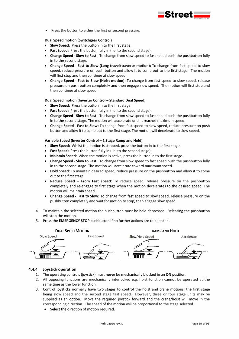
DUAL SPEED MOTION RAMP AND HOLD
4.4.4 Joystick operation 1. The operating controls (joystick) must never be mechanically blocked in an ON position. 2. All opposing functions are mechanically interlocked e.g. hoist function cannot be operated at the
same time as the lower function. 3. Control joysticks normally have two stages to control the hoist and crane motions, the first stage
being slow speed and the second stage fast speed. However, three or four stage units may be supplied as an option. Move the required joystick forward and the crane/hoist will move in the corresponding direction. The speed of the motion will be proportional to the stage selected.
Select the direction of motion required.
defgh © Street Crane Co Ltd
Page 40 of 93 Ref: D3050 Rev D
Single Speed
Move the lever or joystick fully. Dual Speed motion (Switchgear Control)
Slow Speed: Move the joystick to the first stage.
Fast Speed: Move the joystick directly to the second stage.
Change Speed ‐ Slow to Fast: To change from slow speed to fast speed move the joystick fully to the second stage.
Change Speed ‐ Fast to Slow (Long travel/traverse motion): To change from fast speed to slow speed, reduce pressure on the joystick and allow it to come out to the first stage. The motion will first stop and then continue at slow speed.
Change Speed ‐ Fast to Slow (Hoist motion): To change from fast speed to slow speed, release pressure on the joystick completely and then engage slow speed. The motion will first stop and then continue at slow speed.
Dual Speed motion (Inverter Control – Standard Dual Speed)
Slow Speed: Move the joystick to the first stage.
Fast Speed: Move the joystick directly to the second stage.
Change Speed ‐ Slow to Fast: To change from slow speed to fast speed move the joystick fully to the second stage. The motion will accelerate until it reaches maximum speed.
Change Speed ‐ Fast to Slow: To change from fast speed to slow speed, reduce pressure on the joystick and allow it to come out to the first stage. The motion will decelerate to slow speed.
Variable Speed (Inverter Control – 2 Stage Ramp and Hold)
Slow Speed: Whilst the motion is stopped, move the joystick to the first stage.
Fast Speed: Move the joystick directly to the second stage.
Maintain Speed: When the motion is active, push the joystick to the first stage.
Change Speed ‐ Slow to Fast: To change from slow speed to fast speed move the joystick fully to the second stage. The motion will accelerate toward maximum speed.
Hold Speed: To maintain desired speed, reduce pressure on the joystick and allow it to come out to the first stage.
Reduce Speed – From Fast speed: To reduce speed, release pressure on the joystick completely and re‐engage to first stage when the motion decelerates to the desired speed. The motion will maintain speed.
Change Speed ‐ Fast to Slow: To change from fast speed to slow speed, release pressure on the joystick completely and wait for motion to stop, then engage slow speed.
4. To maintain the selected motion the joystick must be held in the selected position. Releasing the
joystick will stop the motion. 5. Press the EMERGENCY STOP pushbutton if no further actions are to be taken.
4.4.5 Emergency Stop
1 Before starting work it is imperative to check the correct operation of the emergency stop button. It is important that the operator is constantly aware and monitoring all crane and hoist movements and ready to activate the emergency stop should any abnormal circumstances arise or situations occur that may endanger the safety of personnel working in the vicinity. Be especially aware of instances where the crane / hoist may fail to stop when the push button / joystick is released or the crane / hoist starts or moves unexpectedly.
1. Depressing the EMERGENCY STOP push button will cause all motions to stop and all brakes to engage. 2. The emergency stop will lock all controls in the off position. 3. If the button is used in an emergency stop situation, ensure that any faults are reported and rectified
before re‐establishing the power supply. 4. Twist to release the EMERGENCY STOP button. No functions will be operative until the emergency
stop is unlatched and the ON pushbutton operated.

defgh © Street Crane Co Ltd
Ref: D3050 rev. D Page 41 of 93
4.5 LEAVING THE CRANE / HOIST UNATTENDED
3 It is essential that a crane / hoist operator is present when a load is suspended from a hoist. When the crane / hoist are left unattended, even for a short period, it is essential that:‐
1. The crane / hoist is parked away from any local sources of heat, fumes, condensation or damp
conditions. 2. Any slings or lifting tackle have been removed from the hook and the hook is raised to a safe position. 3. The Remote control transmitter (where fitted)
Should always be kept in the authorised storage place when not required for immediate use.
The transmitter key must always be turned OFF when not in use and the key removed.
For short periods, the operator should either retain the transmitter in their possession or remove the key from its key lock switch and retain the key in their possession.
4. The Pendant control : ‐
Should be left in a safe location.
Must always be turned OFF by pressing the emergency stop button. 5. The Joystick control (‘ride‐on’ or cab) :‐
The cab must be parked at the authorised access / egress point.
Must always be turned OFF by pressing the emergency stop and removing the key. For short periods, the operator should either retain the key in their possession or for longer periods, the key should be placed at the authorised storage point.
6. For long periods and for out‐of‐service conditions, switch the mains isolator to the OFF position. 7. For outdoor cranes / hoists, attach the storm anchors.
4.6 POWER FAILURE
The appointed person should establish a safe operating procedure in the event of a power failure. If the appointed person does not have such a procedure the following is recommended: ‐
1. Switch off the power supply to the crane / hoist at the main isolator until the electrical supply is restored.
2. If a load is suspended from the hoist, fence off a safe area immediately below / around the load and clear all personnel from that area.
3. A load left suspended in mid‐air is considered to be a hazard it should be lowered to the floor using the hand brake release lever.
Fence off and clear all personnel from the area under the load.
Follow the appropriate Health and Safety regulations and procedures.
Obtain the necessary authorisation / permit for access to the hoist brake.
Carefully lower load to the floor using the hand release on the hoist brake.
1 The load must be lowered under strict control only a few inches at a time before re‐applying the brake. Serious damage and subsequent failure, of the gearbox may result if the load is allowed to ‘run away’.
When load is firmly supported at ground level, re‐apply the brake mechanism. When the electrical supply is restored, re‐establish the crane power supply and carry out the daily pre‐use inspections in section 5.4.
defgh © Street Crane Co Ltd
Page 42 of 93 Ref: D3050 Rev D
5 INSPECTION AND MAINTENANCE INSTRUCTIONS
To ensure that your hoist and / or overhead travelling crane continues to be safe in operation and operates as efficiently as possible, a regular planned inspection and preventative maintenance programme of the equipment is essential. Preventative maintenance, including lubrication, should be undertaken at pre‐set intervals, depending on the crane / hoist duty, with the objective of keeping the equipment in a serviceable condition.
5.1 REPORTING OF DEFECTS AND INCIDENTS
The competent person should have a recognised procedure for reporting defects and incidents. The procedure should include the immediate notification of the following:‐
1. Any defects found during the daily checks. 2. Defects found at any other time. 3. Incidents or accidents, however slight. 4. Shock loads however they occur. 5. Dangerous occurrences or reportable incidents.
5.2 SPECIAL KNOWLEDGE
Some equipment, such as a frequency inverter, may be fitted to the crane / hoist. This equipment requires special knowledge and should only be maintained by persons who are trained and competent in the use of such equipment.
5.3 KEEPING OF RECORDS
Accurate recording of the crane / hoist performance can provide useful information in regulating maintenance procedures and control of replacement stock. Record the date and reading on the hours‐in‐service meter each time a component is replaced and the reason for replacement. See section 7.8.
5.4 DAILY PRE‐USE INSPECTIONS (at the start of each day/shift)
Part of the crane operator’s training should be to make them aware of potential malfunctions requiring adjustments or repairs and the need to bring these to the attention of the competent person for corrective action. The crane / hoist and associated equipment should undergo daily visual and functional checks to ensure that they operate correctly. These can be executed by the operator from floor level.
1 In the event of a malfunction of equipment or unusual occurrences, the operator should immediately REPORT the fault(s) to the competent person. The crane should be taken out of service until the fault(s) have been rectified by the appropriately qualified personnel.
1. Ensure that a “Men Working Overhead” or a “Permit to Work” is not in force. 2. Check all round visibility and carefully note both permanent and temporary hazards. 3. Check that the ropes are correctly seated in the rope groves of drum and sheaves and have not been
displaced. The rope should be free of kinks, protrusions, broken wires and other obvious defects. 4. Check the safety latch on the hook for damage. 5. Check that no electrical equipment is exposed to contamination by oil, grease, water or dirt. 6. Check that any audible and visual warning devices operate correctly. 7. Be familiar with the way in which each controller functions. Ensure that each function button or
joystick, including the emergency stop, on the controller performs its stated operation, (without a load attached) and that each button or joystick returns to the neutral position when released (except emergency stop). Exercise caution whilst making these checks in case of a malfunction.
8. Check that the hoisting and lowering limit switch device operates correctly. To do this, raise or lower the empty hook slowly into the limit position to test its operation.
1 Extreme care should be taken when performing this test. Should the upper limit fail then there is a possibility of damaging the hoist.
defgh © Street Crane Co Ltd
Ref: D3050 rev. D Page 43 of 93
9. Check the operation of any travel and / or traverse limit switches and drives.
1 Do not use ANY limit switch as a regular method of stopping the motion. They are intended as emergency devices and are for the safety of personnel.
10. Check the operation of the hoist brake. To do this lift a load clear of the ground and release the UP
pushbutton. The hook should remain in position with no run‐back.
5.5 HOISTS THAT HAVE BEEN UNUSED FOR AN EXTENDED PERIOD
In cases where the crane / hoist has been out of use for an extended period of time the user should ensure that the competent person specifies a special programme of pre‐use checks. The extent of the checks depends on the length of time the crane has been out of service and the location of the crane during that period. As a minimum the pre‐use checks should include the daily pre‐start inspections mentioned above plus the following:‐
1. Check all ropes for signs of corrosion / degradation and damage and that there is still adequate rope lubricant. Check the entire length of the rope.
2. Check that the RCL (rated capacity limiter) is functioning correctly. 3. Check for corrosion on the structure and mechanisms. 4. Check for damage and missing components or legends. 5. Test every motion for several minutes without load ensuring all brakes work satisfactorily.
The extended period of time should be determined by the competent person and will depend on the conditions and location. As a minimum, we would recommend that operations 1 to 4 above are carried out at least once every 6 months, and operation 5 is carried out monthly.
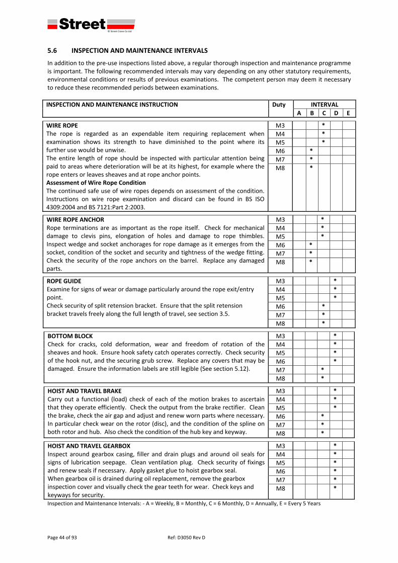
defgh © Street Crane Co Ltd
Page 44 of 93 Ref: D3050 Rev D
5.6 INSPECTION AND MAINTENANCE INTERVALS
In addition to the pre‐use inspections listed above, a regular thorough inspection and maintenance programme is important. The following recommended intervals may vary depending on any other statutory requirements, environmental conditions or results of previous examinations. The competent person may deem it necessary to reduce these recommended periods between examinations.
INSPECTION AND MAINTENANCE INSTRUCTION
Duty INTERVAL
A B C D E
WIRE ROPE The rope is regarded as an expendable item requiring replacement when examination shows its strength to have diminished to the point where its further use would be unwise. The entire length of rope should be inspected with particular attention being paid to areas where deterioration will be at its highest, for example where the rope enters or leaves sheaves and at rope anchor points. Assessment of Wire Rope Condition The continued safe use of wire ropes depends on assessment of the condition. Instructions on wire rope examination and discard can be found in BS ISO 4309:2004 and BS 7121:Part 2:2003.
M3 *
M4 *
M5 *
M6 *
M7 *
M8 *
WIRE ROPE ANCHOR Rope terminations are as important as the rope itself. Check for mechanical damage to clevis pins, elongation of holes and damage to rope thimbles. Inspect wedge and socket anchorages for rope damage as it emerges from the socket, condition of the socket and security and tightness of the wedge fitting. Check the security of the rope anchors on the barrel. Replace any damaged parts.
M3 *
M4 *
M5 *
M6 *
M7 *
M8 *
ROPE GUIDE Examine for signs of wear or damage particularly around the rope exit/entry point. Check security of split retension bracket. Ensure that the split retension bracket travels freely along the full length of travel, see section 3.5.
M3 *
M4 *
M5 *
M6 *
M7 *
M8 *
BOTTOM BLOCK Check for cracks, cold deformation, wear and freedom of rotation of the sheaves and hook. Ensure hook safety catch operates correctly. Check security of the hook nut, and the securing grub screw. Replace any covers that may be damaged. Ensure the information labels are still legible (See section 5.12).
M3 *
M4 *
M5 *
M6 *
M7 *
M8 *
HOIST AND TRAVEL BRAKECarry out a functional (load) check of each of the motion brakes to ascertain that they operate efficiently. Check the output from the brake rectifier. Clean the brake, check the air gap and adjust and renew worn parts where necessary. In particular check wear on the rotor (disc), and the condition of the spline on both rotor and hub. Also check the condition of the hub key and keyway.
M3 *
M4 *
M5 *
M6 *
M7 *
M8 *
HOIST AND TRAVEL GEARBOX Inspect around gearbox casing, filler and drain plugs and around oil seals for signs of lubrication seepage. Clean ventilation plug. Check security of fixings and renew seals if necessary. Apply gasket glue to hoist gearbox seal. When gearbox oil is drained during oil replacement, remove the gearbox inspection cover and visually check the gear teeth for wear. Check keys and keyways for security.
M3 *
M4 *
M5 *
M6 *
M7 *
M8 *
Inspection and Maintenance Intervals: ‐ A = Weekly, B = Monthly, C = 6 Monthly, D = Annually, E = Every 5 Years
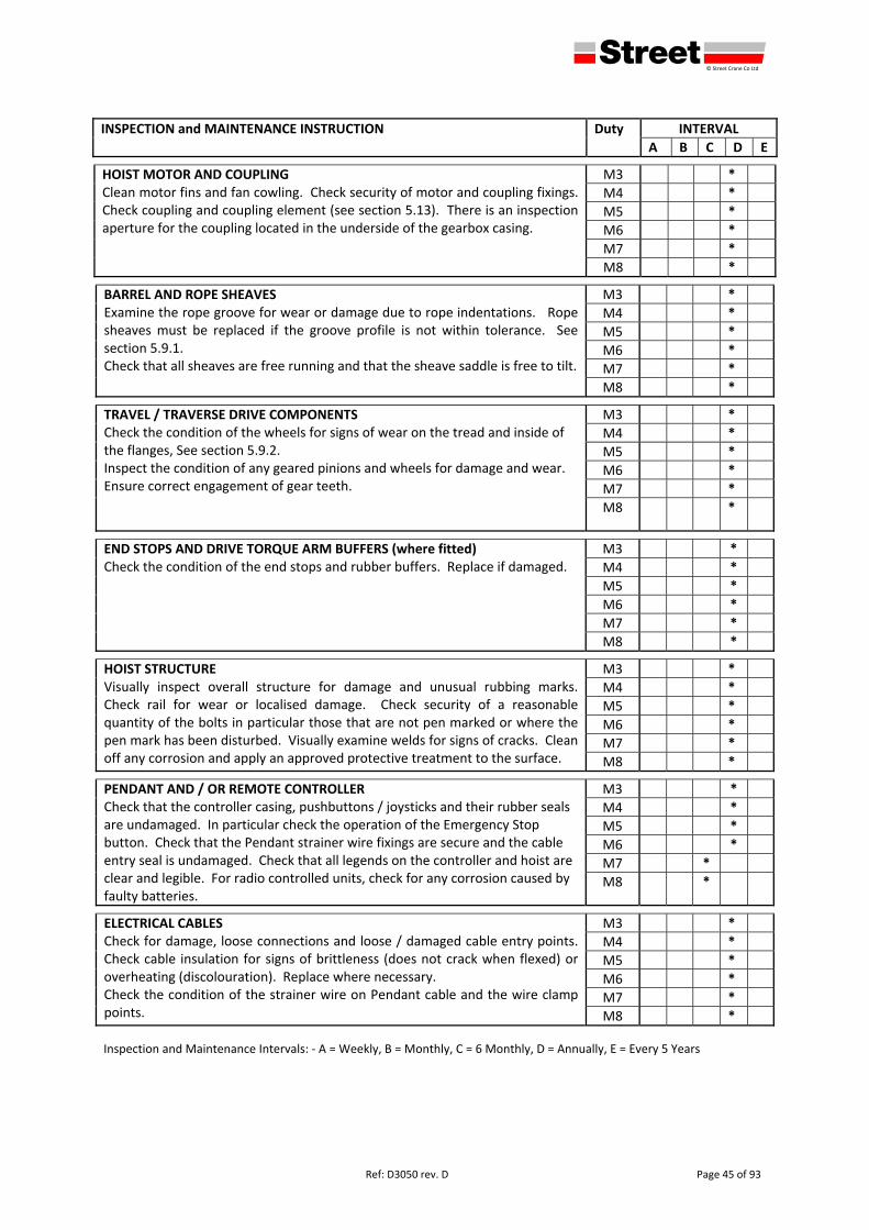
defgh © Street Crane Co Ltd
Ref: D3050 rev. D Page 45 of 93
INSPECTION and MAINTENANCE INSTRUCTION
Duty INTERVAL
A B C D E
HOIST MOTOR AND COUPLING Clean motor fins and fan cowling. Check security of motor and coupling fixings. Check coupling and coupling element (see section 5.13). There is an inspection aperture for the coupling located in the underside of the gearbox casing.
M3 *
M4 *
M5 *
M6 *
M7 *
M8 *
BARREL AND ROPE SHEAVES Examine the rope groove for wear or damage due to rope indentations. Rope sheaves must be replaced if the groove profile is not within tolerance. See section 5.9.1. Check that all sheaves are free running and that the sheave saddle is free to tilt.
M3 *
M4 *
M5 *
M6 *
M7 *
M8 *
TRAVEL / TRAVERSE DRIVE COMPONENTS Check the condition of the wheels for signs of wear on the tread and inside of the flanges, See section 5.9.2. Inspect the condition of any geared pinions and wheels for damage and wear. Ensure correct engagement of gear teeth.
M3 *
M4 *
M5 *
M6 *
M7 *
M8 *
END STOPS AND DRIVE TORQUE ARM BUFFERS (where fitted)Check the condition of the end stops and rubber buffers. Replace if damaged.
M3 *
M4 *
M5 *
M6 *
M7 *
M8 *
HOIST STRUCTURE Visually inspect overall structure for damage and unusual rubbing marks. Check rail for wear or localised damage. Check security of a reasonable quantity of the bolts in particular those that are not pen marked or where the pen mark has been disturbed. Visually examine welds for signs of cracks. Clean off any corrosion and apply an approved protective treatment to the surface.
M3 *
M4 *
M5 *
M6 *
M7 *
M8 *
PENDANT AND / OR REMOTE CONTROLLERCheck that the controller casing, pushbuttons / joysticks and their rubber seals are undamaged. In particular check the operation of the Emergency Stop button. Check that the Pendant strainer wire fixings are secure and the cable entry seal is undamaged. Check that all legends on the controller and hoist are clear and legible. For radio controlled units, check for any corrosion caused by faulty batteries.
M3 *
M4 *
M5 *
M6 *
M7 *
M8 *
ELECTRICAL CABLES Check for damage, loose connections and loose / damaged cable entry points. Check cable insulation for signs of brittleness (does not crack when flexed) or overheating (discolouration). Replace where necessary. Check the condition of the strainer wire on Pendant cable and the wire clamp points.
M3 *
M4 *
M5 *
M6 *
M7 *
M8 *
Inspection and Maintenance Intervals: ‐ A = Weekly, B = Monthly, C = 6 Monthly, D = Annually, E = Every 5 Years
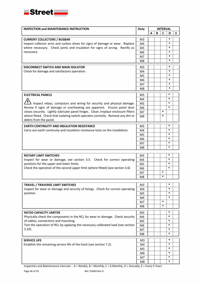
defgh © Street Crane Co Ltd
Page 46 of 93 Ref: D3050 Rev D
INSPECTION and MAINTENANCE INSTRUCTION
Duty INTERVAL
A B C D E
CURRENT COLLECTORS / BUSBAR Inspect collector arms and carbon shoes for signs of damage or wear. Replace where necessary. Check joints and insulation for signs of arcing. Rectify as necessary.
M3 *
M4 *
M5 *
M6 *
M7 *
M8 *
DISCONNECT SWITCH AND MAIN ISOLATORCheck for damage and satisfactory operation.
M3 *
M4 *
M5 *
M6 *
M7 *
M8 *
ELECTRICAL PANELS
2 Inspect relays, contactors and wiring for security and physical damage. Renew if signs of damage or overheating are apparent. Ensure panel door closes securely. Lightly lubricate panel hinges. Clean /replace enclosure filters where fitted. Check that isolating switch operates correctly. Remove any dirt or debris from the panel.
M3 *
M4 *
M5 *
M6 *
M7 *
M8 *
EARTH CONTINUITY AND INSULATION RESISTANCECarry out earth continuity and insulation resistance tests on the installation.
M3 *
M4 *
M5 *
M6 *
M7 *
M8 *
ROTARY LIMIT SWITCHESInspect for wear or damage, see section 3.5. Check for correct operating positions for the upper and lower limits. Check the operation of the second upper limit (where fitted) (see section 3.6)
M3 *
M4 *
M5 *
M6 *
M7 *
M8 *
TRAVEL / TRAVERSE LIMIT SWITCHES Inspect for wear or damage and security of fixings. Check for correct operating position.
M3 *
M4 *
M5 *
M6 *
M7 *
M8 *
RATED CAPACITY LIMITERPhysically check the components in the RCL for wear or damage. Check security of cables, connections and mounting. Test the operation of RCL by applying the necessary calibrated load (see section 3.10).
M3 *
M4 *
M5 *
M6 *
M7 *
M8 *
SERVICE LIFE Establish the remaining service life of the hoist (see section 7.2).
M3 *
M4 *
M5 *
M6 *
M7 *
M8 *Inspection and Maintenance Intervals: ‐ A = Weekly, B = Monthly, C = 6 Monthly, D = Annually, E = Every 5 Years
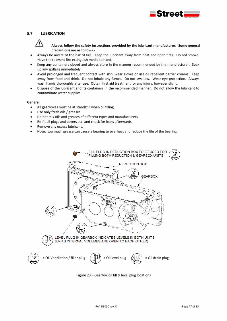
defgh © Street Crane Co Ltd
Ref: D3050 rev. D Page 47 of 93
5.7 LUBRICATION
1 Always follow the safety instructions provided by the lubricant manufacturer. Some general precautions are as follows:‐
Always be aware of the risk of fire. Keep the lubricant away from heat and open fires. Do not smoke. Have the relevant fire extinguish media to hand.
Keep any containers closed and always store in the manner recommended by the manufacturer. Soak up any spillage immediately.
Avoid prolonged and frequent contact with skin, wear gloves or use oil repellent barrier creams. Keep away from food and drink. Do not inhale any fumes. Do not swallow. Wear eye protection. Always wash hands thoroughly after use. Obtain first aid treatment for any injury, however slight.
Dispose of the lubricant and its containers in the recommended manner. Do not allow the lubricant to contaminate water supplies.
General
All gearboxes must be at standstill when oil filling.
Use only fresh oils / greases
Do not mix oils and greases of different types and manufacturers.
Re‐fit all plugs and covers etc. and check for leaks afterwards.
Remove any excess lubricant.
Note: too much grease can cause a bearing to overheat and reduce the life of the bearing.
= Oil Ventilation / filler plug = Oil level plug = Oil drain plug
Figure 23 – Gearbox oil fill & level plug locations
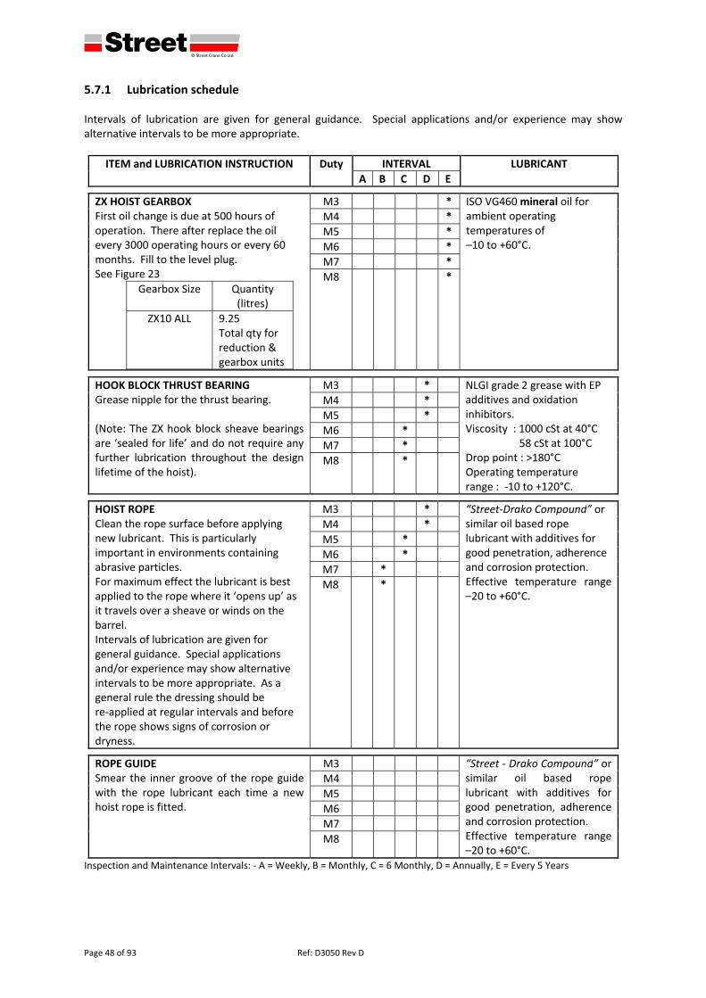
defgh © Street Crane Co Ltd
Page 48 of 93 Ref: D3050 Rev D
5.7.1 Lubrication schedule Intervals of lubrication are given for general guidance. Special applications and/or experience may show alternative intervals to be more appropriate.
ITEM and LUBRICATION INSTRUCTION Duty INTERVAL LUBRICANT
A B C D E
ZX HOIST GEARBOX First oil change is due at 500 hours of operation. There after replace the oil every 3000 operating hours or every 60 months. Fill to the level plug. See Figure 23
Gearbox Size Quantity (litres)
ZX10 ALL 9.25 Total qty for reduction & gearbox units
M3 * ISO VG460 mineral oil for ambient operating temperatures of –10 to +60°C.
M4 *
M5 *
M6 *
M7 *
M8 *
HOOK BLOCK THRUST BEARING Grease nipple for the thrust bearing. (Note: The ZX hook block sheave bearings are ‘sealed for life’ and do not require any further lubrication throughout the design lifetime of the hoist).
M3 * NLGI grade 2 grease with EP additives and oxidation inhibitors. Viscosity : 1000 cSt at 40°C 58 cSt at 100°C Drop point : >180°C Operating temperature range : ‐10 to +120°C.
M4 *
M5 *
M6 *
M7 *
M8 *
HOIST ROPE Clean the rope surface before applying new lubricant. This is particularly important in environments containing abrasive particles. For maximum effect the lubricant is best applied to the rope where it ‘opens up’ as it travels over a sheave or winds on the barrel. Intervals of lubrication are given for general guidance. Special applications and/or experience may show alternative intervals to be more appropriate. As a general rule the dressing should be re‐applied at regular intervals and before the rope shows signs of corrosion or dryness.
M3 * “Street‐Drako Compound” or similar oil based rope lubricant with additives for good penetration, adherence and corrosion protection. Effective temperature range –20 to +60°C.
M4 *
M5 *
M6 *
M7 *
M8 *
ROPE GUIDE Smear the inner groove of the rope guide with the rope lubricant each time a new hoist rope is fitted.
M3 “Street ‐ Drako Compound” or similar oil based rope lubricant with additives for good penetration, adherence and corrosion protection. Effective temperature range –20 to +60°C.
M4
M5
M6
M7
M8
Inspection and Maintenance Intervals: ‐ A = Weekly, B = Monthly, C = 6 Monthly, D = Annually, E = Every 5 Years
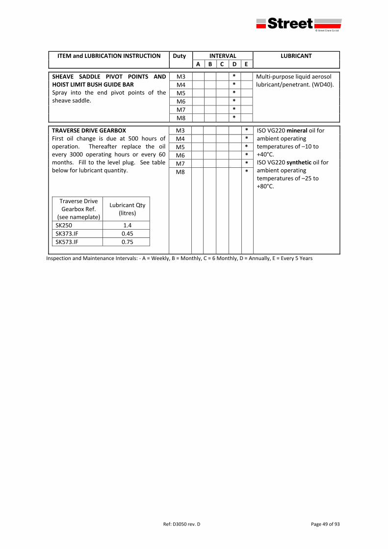
defgh © Street Crane Co Ltd
Ref: D3050 rev. D Page 49 of 93
ITEM and LUBRICATION INSTRUCTION Duty INTERVAL LUBRICANT
A B C D E
SHEAVE SADDLE PIVOT POINTS AND HOIST LIMIT BUSH GUIDE BAR Spray into the end pivot points of the sheave saddle.
M3 * Multi‐purpose liquid aerosol lubricant/penetrant. (WD40). M4 *
M5 *
M6 *
M7 *
M8 *
TRAVERSE DRIVE GEARBOX First oil change is due at 500 hours of operation. Thereafter replace the oil every 3000 operating hours or every 60 months. Fill to the level plug. See table below for lubricant quantity.
Traverse Drive Gearbox Ref.
(see nameplate)
Lubricant Qty (litres)
SK250 1.4
SK373.IF 0.45
SK573.IF 0.75
M3 * ISO VG220 mineral oil for ambient operating temperatures of –10 to +40°C. ISO VG220 synthetic oil for ambient operating temperatures of –25 to +80°C.
M4 *
M5 *
M6 *
M7 *
M8 *
Inspection and Maintenance Intervals: ‐ A = Weekly, B = Monthly, C = 6 Monthly, D = Annually, E = Every 5 Years
defgh © Street Crane Co Ltd
Page 50 of 93 Ref: D3050 Rev D
5.8 INSPECTION AND MAINTENANCE – WIRE ROPE
1 Failure of a wire rope may cause death or serious injury. A wire rope will fail if worn out, shock loaded, overloaded, miss‐used, damaged, abused or improperly maintained. Information on care, maintenance, installation, examination and discard of wire ropes can be found in BS ISO 4309:2004 and / or BS 7121‐1:2006. The competent person should hold a copy of these documents.
1 Do not replace a rope or any rope fittings with anything other than to the original specification. This applies equally to the rope length as well as its construction.
The Rope Data Plate is located in the vicinity of the Hoist Nameplate (see 2.1) and contains all the
required rope replacement information.
5.8.1 Offloading and Storage Care of a new rope begins immediately upon receipt. Use wide textile webbing slings or lift on the rope drum to avoid direct contact with the rope. Inspect the rope upon receipt and ensure that the details on the certificate and other documents are correct. Clearly label the rope and ensure that it is traceable to its certificate and / or other documents. Steel wire ropes should be stored in a clean, cool, dry place, indoors and away from corrosive and damp atmospheres. Do not let the rope rest directly on the floor allow air to circulate around the reel. Cover with a breathable cover that prevents condensation. Inspect the rope periodically and if necessary, apply a suitable dressing that is compatible with the manufacturer’s lubricant see section 5.7.1. When removing from storage, check that no accidental damage has occurred and that there are no signs of corrosion. Ensure the rope certificate is available and retain this in a safe place, it will be required when periodic examinations are carried out.
5.8.2 Replacing the Wire Rope
1 Removal and replacing the wire rope is most effectively carried out with the power to the hoist unit switched ON so all work must be carried out with extreme care. Suitable safety precautions should be made to ensure that other motions are not accidentally activated, i.e. isolate any travel motions.
It may be necessary to adjust the lower limit to allow the block to lower to ground level. NOTE: The upper and lower limit will require resetting after completion of new rope installation.
5.8.2.1 Removing the Rope Lower the bottom block down to the lowest possible level and allow the block to rest on a solid support
(floor or platform).
Run the remaining rope off the barrel until approx 1 full wrap remains at each barrel end.
Carefully release the pair of rope clamps at one end of barrel and lower that end of rope to the floor.
Repeat for the other end of rope.
Withdraw the rope through the bottom block and hoist sheaves.
5.8.2.2 Fitting New Wire Rope
1 Fitting the wire rope is most effectively carried out with the power to the hoist unit switched ON so all work must be carried out with extreme care. Suitable safety precautions should be made to ensure that other motions are not accidentally activated, i.e. isolate any travel motions.
Fitting of a new rope must be carried out by a competent person. Before installation check that all sheaves are free running and rope grooves in sheaves and drums are in good condition. Groove profiles should be circular, smooth and free from ridges (see 5.9.1). Check that the correct rope has been ordered / taken out of storage. Examine the rope visually to ensure that there is no damage or corrosion on the rope. Prepare a safe and clean working area to avoid contaminating the rope with any dirt or moisture.
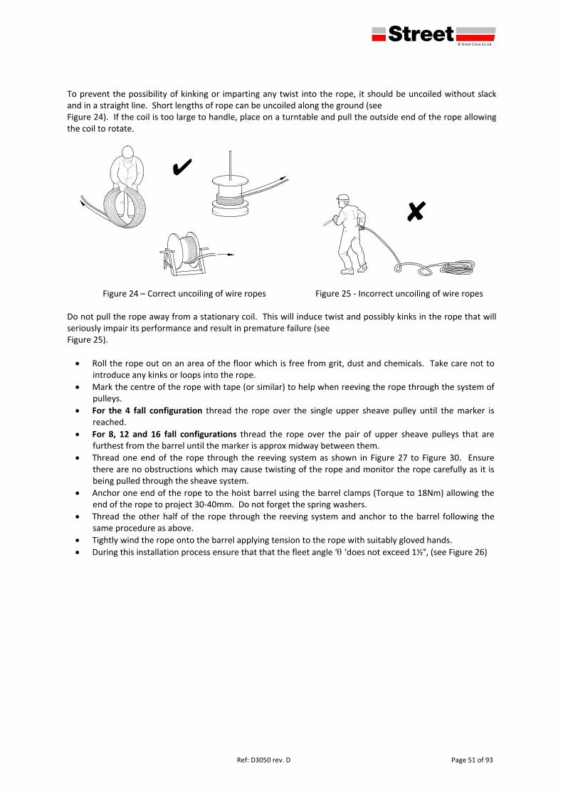
defgh © Street Crane Co Ltd
Ref: D3050 rev. D Page 51 of 93
To prevent the possibility of kinking or imparting any twist into the rope, it should be uncoiled without slack and in a straight line. Short lengths of rope can be uncoiled along the ground (see Figure 24). If the coil is too large to handle, place on a turntable and pull the outside end of the rope allowing the coil to rotate.
Figure 24 – Correct uncoiling of wire ropes
Figure 25 ‐ Incorrect uncoiling of wire ropes
Do not pull the rope away from a stationary coil. This will induce twist and possibly kinks in the rope that will seriously impair its performance and result in premature failure (see Figure 25).
Roll the rope out on an area of the floor which is free from grit, dust and chemicals. Take care not to introduce any kinks or loops into the rope.
Mark the centre of the rope with tape (or similar) to help when reeving the rope through the system of pulleys.
For the 4 fall configuration thread the rope over the single upper sheave pulley until the marker is reached.
For 8, 12 and 16 fall configurations thread the rope over the pair of upper sheave pulleys that are furthest from the barrel until the marker is approx midway between them.
Thread one end of the rope through the reeving system as shown in Figure 27 to Figure 30. Ensure there are no obstructions which may cause twisting of the rope and monitor the rope carefully as it is being pulled through the sheave system.
Anchor one end of the rope to the hoist barrel using the barrel clamps (Torque to 18Nm) allowing the end of the rope to project 30‐40mm. Do not forget the spring washers.
Thread the other half of the rope through the reeving system and anchor to the barrel following the same procedure as above.
Tightly wind the rope onto the barrel applying tension to the rope with suitably gloved hands.
During this installation process ensure that that the fleet angle ‘ ‘does not exceed 1½°, (see Figure 26)
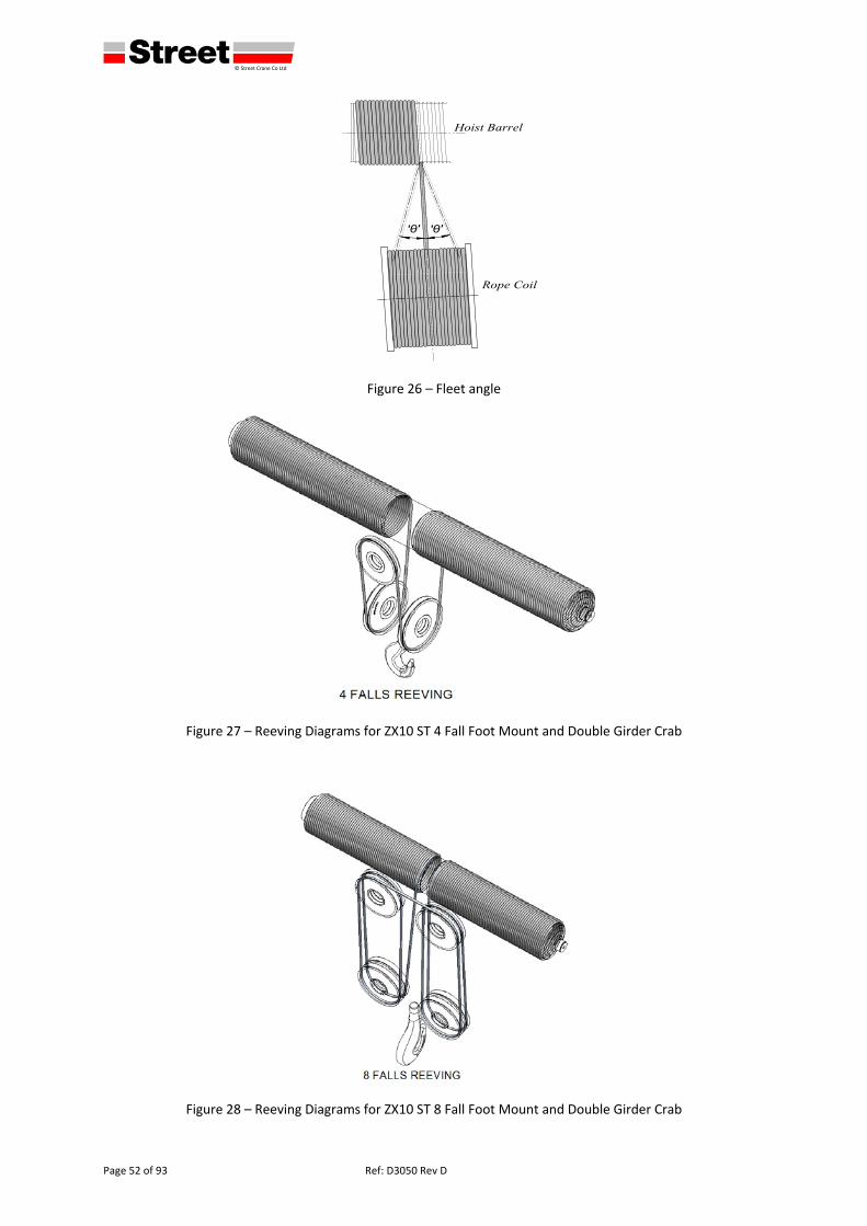
defgh © Street Crane Co Ltd
Page 52 of 93 Ref: D3050 Rev D
Figure 26 – Fleet angle
Figure 27 – Reeving Diagrams for ZX10 ST 4 Fall Foot Mount and Double Girder Crab
Figure 28 – Reeving Diagrams for ZX10 ST 8 Fall Foot Mount and Double Girder Crab
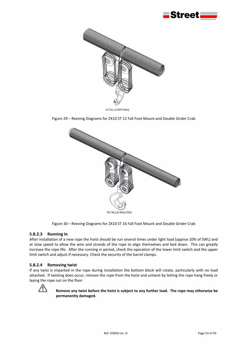
defgh © Street Crane Co Ltd
Ref: D3050 rev. D Page 53 of 93
Figure 29 – Reeving Diagrams for ZX10 ST 12 Fall Foot Mount and Double Girder Crab
Figure 30 – Reeving Diagrams for ZX10 ST 16 Fall Foot Mount and Double Girder Crab
5.8.2.3 Running In After installation of a new rope the hoist should be run several times under light load (approx 10% of SWL) and at slow speed to allow the wire and strands of the rope to align themselves and bed down. This can greatly increase the rope life. After the running in period, check the operation of the lower limit switch and the upper limit switch and adjust if necessary. Check the security of the barrel clamps.
5.8.2.4 Removing twist If any twist is imparted in the rope during installation the bottom block will rotate, particularly with no load attached. If twisting does occur, remove the rope from the hoist and untwist by letting the rope hang freely or laying the rope out on the floor.
1 Remove any twist before the hoist is subject to any further load. The rope may otherwise be permanently damaged.
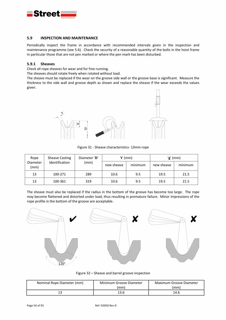
defgh © Street Crane Co Ltd
Page 54 of 93 Ref: D3050 Rev D
5.9 INSPECTION AND MAINTENANCE
Periodically inspect the frame in accordance with recommended intervals given in the inspection and maintenance programme (see 5.6). Check the security of a reasonable quantity of the bolts in the hoist frame in particular those that are not pen marked or where the pen mark has been disturbed.
5.9.1 Sheaves Check all rope sheaves for wear and for free running. The sheaves should rotate freely when rotated without load. The sheave must be replaced if the wear on the groove side wall or the groove base is significant. Measure the thickness to the side wall and groove depth as shown and replace the sheave if the wear exceeds the values given.
Figure 31 ‐ Sheave characteristics‐ 13mm rope
Rope Diameter (mm)
Sheave Casting Identification
Diameter ‘D’ (mm)
‘t’ (mm) ‘g’ (mm)
new sheave minimum new sheave minimum
13 100‐271 289 10.6 9.5 19.5 21.5
13 100‐361 319 10.6 9.5 19.5 21.5
The sheave must also be replaced if the radius in the bottom of the groove has become too large. The rope may become flattened and distorted under load, thus resulting in premature failure. Minor impressions of the rope profile in the bottom of the groove are acceptable.
Figure 32 – Sheave and barrel groove inspection
Nominal Rope Diameter (mm) Minimum Groove Diameter (mm)
Maximum Groove Diameter (mm)
13 13.6 14.6
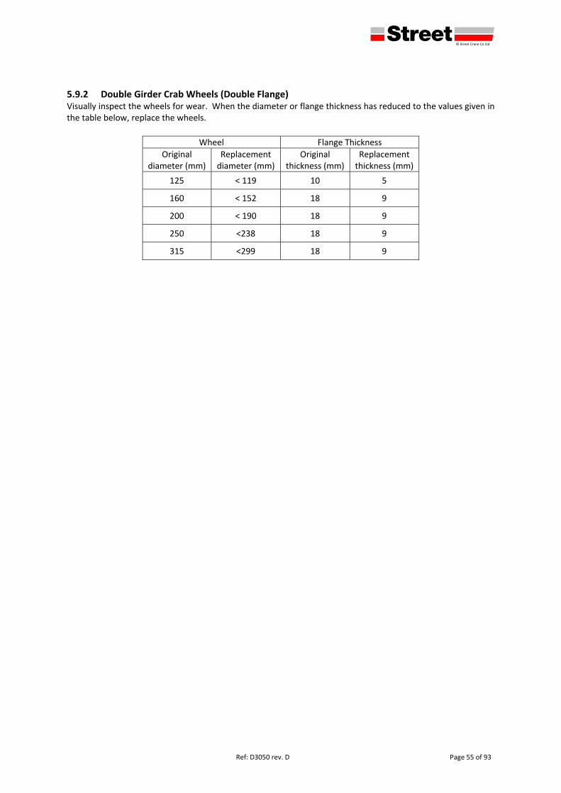
defgh © Street Crane Co Ltd
Ref: D3050 rev. D Page 55 of 93
5.9.2 Double Girder Crab Wheels (Double Flange) Visually inspect the wheels for wear. When the diameter or flange thickness has reduced to the values given in the table below, replace the wheels.
Wheel Flange Thickness
Original diameter (mm)
Replacement diameter (mm)
Original thickness (mm)
Replacement thickness (mm)
125 < 119 10 5
160 < 152 18 9
200 < 190 18 9
250 <238 18 9
315 <299 18 9
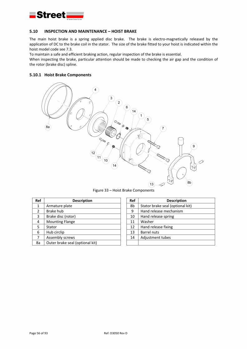
defgh © Street Crane Co Ltd
Page 56 of 93 Ref: D3050 Rev D
5.10 INSPECTION AND MAINTENANCE – HOIST BRAKE
The main hoist brake is a spring applied disc brake. The brake is electro‐magnetically released by the application of DC to the brake coil in the stator. The size of the brake fitted to your hoist is indicated within the hoist model code see 7.3. To maintain a safe and efficient braking action, regular inspection of the brake is essential. When inspecting the brake, particular attention should be made to checking the air gap and the condition of the rotor (brake disc) spline.
5.10.1 Hoist Brake Components
Figure 33 – Hoist Brake Components
Ref Description Ref Description
1 Armature plate 8b Stator brake seal (optional kit)
2 Brake hub 9 Hand release mechanism
3 Brake disc (rotor) 10 Hand release spring
4 Mounting Flange 11 Washer
5 Stator 12 Hand release fixing
6 Hub circlip 13 Barrel nuts
7 Assembly screws 14 Adjustment tubes
8a Outer brake seal (optional kit)
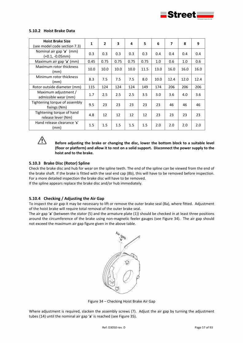
defgh © Street Crane Co Ltd
Ref: D3050 rev. D Page 57 of 93
5.10.2 Hoist Brake Data
Hoist Brake Size (see model code section 7.3)
1 2 3 4 5 6 7 8 9
Nominal air gap ‘a’ (mm) (+0.1, ‐0.05mm)
0.3 0.3 0.3 0.3 0.3 0.4 0.4 0.4 0.4
Maximum air gap ‘a’ (mm) 0.45 0.75 0.75 0.75 0.75 1.0 0.6 1.0 0.6
Maximum rotor thickness (mm)
10.0 10.0 10.0 10.0 11.5 13.0 16.0 16.0 16.0
Minimum rotor thickness (mm)
8.3 7.5 7.5 7.5 8.0 10.0 12.4 12.0 12.4
Rotor outside diameter (mm) 115 124 124 124 149 174 206 206 206
Maximum adjustment / admissible wear (mm)
1.7 2.5 2.5 2.5 3.5 3.0 3.6 4.0 3.6
Tightening torque of assembly fixings (Nm)
9.5 23 23 23 23 23 46 46 46
Tightening torque of hand release lever (Nm)
4.8 12 12 12 12 23 23 23 23
Hand release clearance ‘s’ (mm)
1.5 1.5 1.5 1.5 1.5 2.0 2.0 2.0 2.0
1 Before adjusting the brake or changing the disc, lower the bottom block to a suitable level (floor or platform) and allow it to rest on a solid support. Disconnect the power supply to the hoist and to the brake.
5.10.3 Brake Disc (Rotor) Spline Check the brake disc and hub for wear on the spline teeth. The end of the spline can be viewed from the end of the brake shaft. If the brake is fitted with the seal end cap (8b), this will have to be removed before inspection. For a more detailed inspection the brake disc will have to be removed. If the spline appears replace the brake disc and/or hub immediately.
5.10.4 Checking / Adjusting the Air Gap To inspect the air gap it may be necessary to lift or remove the outer brake seal (8a), where fitted. Adjustment of the hoist brake will require total removal of the outer brake seal. The air gap ‘a’ (between the stator (5) and the armature plate (1)) should be checked in at least three positions around the circumference of the brake using non‐magnetic feeler gauges (see Figure 34). The air gap should not exceed the maximum air gap figure given in the above table.
Figure 34 – Checking Hoist Brake Air Gap Where adjustment is required, slacken the assembly screws (7). Adjust the air gap by turning the adjustment tubes (14) until the nominal air gap ‘a’ is reached (see Figure 35).
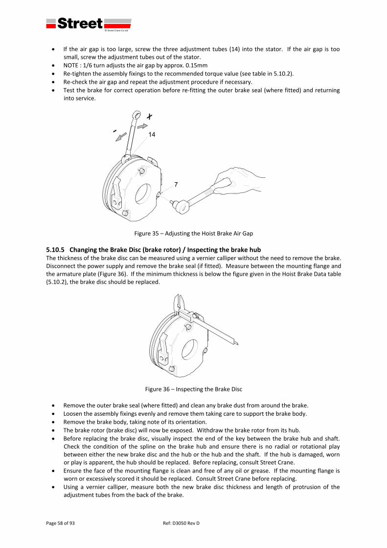
defgh © Street Crane Co Ltd
Page 58 of 93 Ref: D3050 Rev D
If the air gap is too large, screw the three adjustment tubes (14) into the stator. If the air gap is too small, screw the adjustment tubes out of the stator.
NOTE : 1/6 turn adjusts the air gap by approx. 0.15mm
Re‐tighten the assembly fixings to the recommended torque value (see table in 5.10.2).
Re‐check the air gap and repeat the adjustment procedure if necessary.
Test the brake for correct operation before re‐fitting the outer brake seal (where fitted) and returning into service.
Figure 35 – Adjusting the Hoist Brake Air Gap
5.10.5 Changing the Brake Disc (brake rotor) / Inspecting the brake hub The thickness of the brake disc can be measured using a vernier calliper without the need to remove the brake. Disconnect the power supply and remove the brake seal (if fitted). Measure between the mounting flange and the armature plate (Figure 36). If the minimum thickness is below the figure given in the Hoist Brake Data table (5.10.2), the brake disc should be replaced.
Figure 36 – Inspecting the Brake Disc
Remove the outer brake seal (where fitted) and clean any brake dust from around the brake.
Loosen the assembly fixings evenly and remove them taking care to support the brake body.
Remove the brake body, taking note of its orientation.
The brake rotor (brake disc) will now be exposed. Withdraw the brake rotor from its hub.
Before replacing the brake disc, visually inspect the end of the key between the brake hub and shaft. Check the condition of the spline on the brake hub and ensure there is no radial or rotational play between either the new brake disc and the hub or the hub and the shaft. If the hub is damaged, worn or play is apparent, the hub should be replaced. Before replacing, consult Street Crane.
Ensure the face of the mounting flange is clean and free of any oil or grease. If the mounting flange is worn or excessively scored it should be replaced. Consult Street Crane before replacing.
Using a vernier calliper, measure both the new brake disc thickness and length of protrusion of the adjustment tubes from the back of the brake.
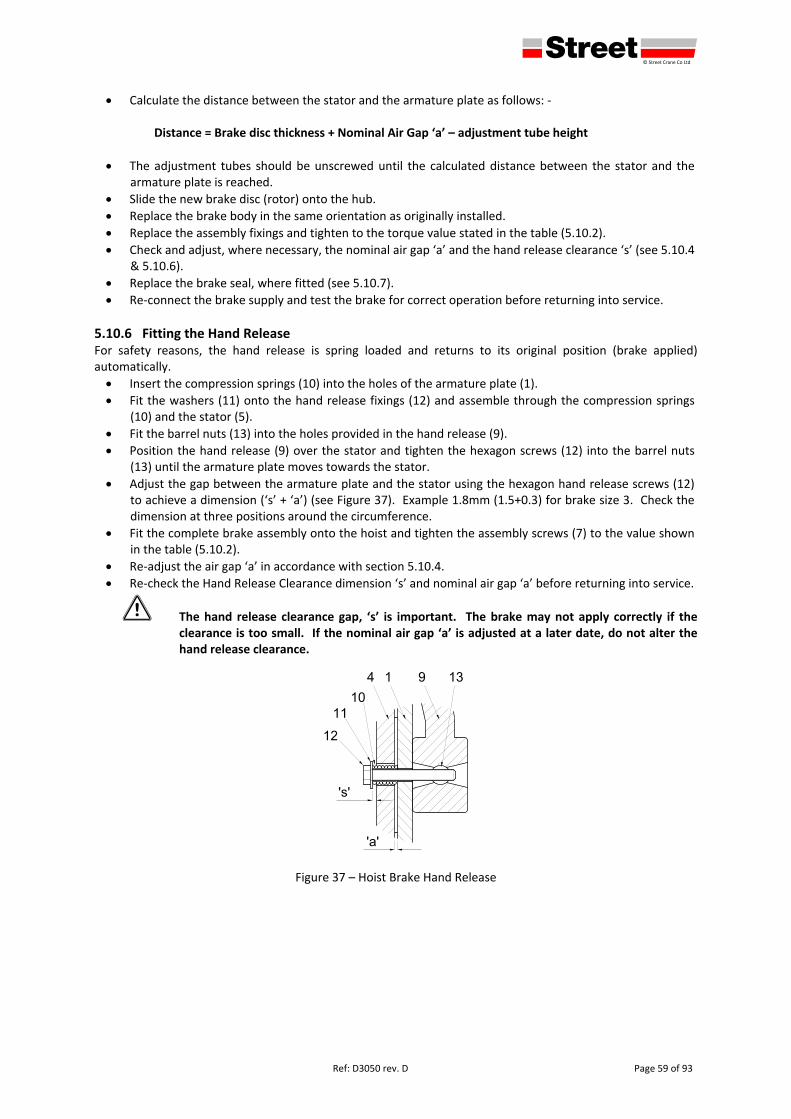
defgh © Street Crane Co Ltd
Ref: D3050 rev. D Page 59 of 93
Calculate the distance between the stator and the armature plate as follows: ‐ Distance = Brake disc thickness + Nominal Air Gap ‘a’ – adjustment tube height
The adjustment tubes should be unscrewed until the calculated distance between the stator and the armature plate is reached.
Slide the new brake disc (rotor) onto the hub.
Replace the brake body in the same orientation as originally installed.
Replace the assembly fixings and tighten to the torque value stated in the table (5.10.2).
Check and adjust, where necessary, the nominal air gap ‘a’ and the hand release clearance ‘s’ (see 5.10.4 & 5.10.6).
Replace the brake seal, where fitted (see 5.10.7).
Re‐connect the brake supply and test the brake for correct operation before returning into service.
5.10.6 Fitting the Hand Release For safety reasons, the hand release is spring loaded and returns to its original position (brake applied) automatically.
Insert the compression springs (10) into the holes of the armature plate (1).
Fit the washers (11) onto the hand release fixings (12) and assemble through the compression springs (10) and the stator (5).
Fit the barrel nuts (13) into the holes provided in the hand release (9).
Position the hand release (9) over the stator and tighten the hexagon screws (12) into the barrel nuts (13) until the armature plate moves towards the stator.
Adjust the gap between the armature plate and the stator using the hexagon hand release screws (12) to achieve a dimension (‘s’ + ‘a’) (see Figure 37). Example 1.8mm (1.5+0.3) for brake size 3. Check the dimension at three positions around the circumference.
Fit the complete brake assembly onto the hoist and tighten the assembly screws (7) to the value shown in the table (5.10.2).
Re‐adjust the air gap ‘a’ in accordance with section 5.10.4.
Re‐check the Hand Release Clearance dimension ‘s’ and nominal air gap ‘a’ before returning into service.
1 The hand release clearance gap, ‘s’ is important. The brake may not apply correctly if the clearance is too small. If the nominal air gap ‘a’ is adjusted at a later date, do not alter the hand release clearance.
Figure 37 – Hoist Brake Hand Release
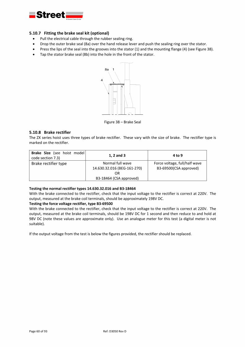
defgh © Street Crane Co Ltd
Page 60 of 93 Ref: D3050 Rev D
5.10.7 Fitting the brake seal kit (optional) Pull the electrical cable through the rubber sealing ring.
Drop the outer brake seal (8a) over the hand release lever and push the sealing ring over the stator.
Press the lips of the seal into the grooves into the stator (1) and the mounting flange (4) (see Figure 38).
Tap the stator brake seal (8b) into the hole in the front of the stator.
Figure 38 – Brake Seal
5.10.8 Brake rectifier The ZX series hoist uses three types of brake rectifier. These vary with the size of brake. The rectifier type is marked on the rectifier.
Brake Size (see hoist model code section 7.3)
1, 2 and 3 4 to 9
Brake rectifier type Normal full wave14.630.32.016 (BEG‐161‐270)
OR B3‐18464 (CSA approved)
Force voltage, full/half wave B3‐69500(CSA approved)
Testing the normal rectifier types 14.630.32.016 and B3‐18464 With the brake connected to the rectifier, check that the input voltage to the rectifier is correct at 220V. The output, measured at the brake coil terminals, should be approximately 198V DC. Testing the force voltage rectifier, type B3‐69500 With the brake connected to the rectifier, check that the input voltage to the rectifier is correct at 220V. The output, measured at the brake coil terminals, should be 198V DC for 1 second and then reduce to and hold at 98V DC (note these values are approximate only). Use an analogue meter for this test (a digital meter is not suitable). If the output voltage from the test is below the figures provided, the rectifier should be replaced.
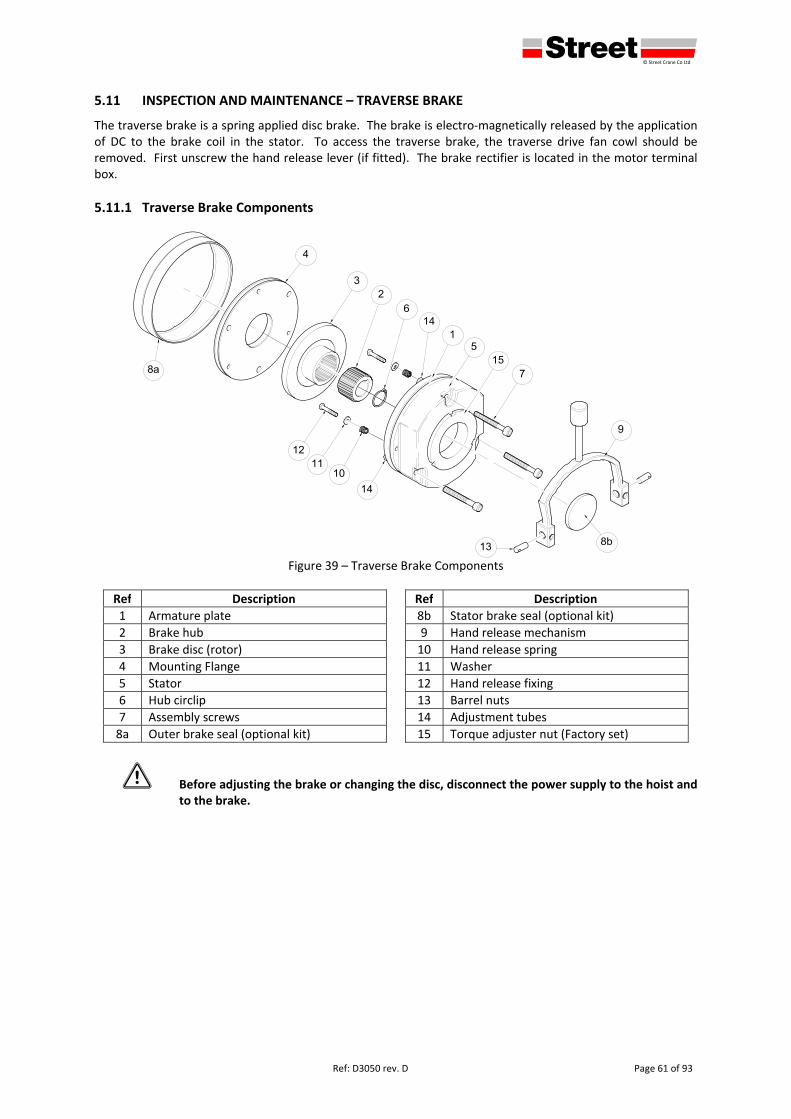
defgh © Street Crane Co Ltd
Ref: D3050 rev. D Page 61 of 93
5.11 INSPECTION AND MAINTENANCE – TRAVERSE BRAKE
The traverse brake is a spring applied disc brake. The brake is electro‐magnetically released by the application of DC to the brake coil in the stator. To access the traverse brake, the traverse drive fan cowl should be removed. First unscrew the hand release lever (if fitted). The brake rectifier is located in the motor terminal box.
5.11.1 Traverse Brake Components
Figure 39 – Traverse Brake Components
Ref Description Ref Description
1 Armature plate 8b Stator brake seal (optional kit)
2 Brake hub 9 Hand release mechanism
3 Brake disc (rotor) 10 Hand release spring
4 Mounting Flange 11 Washer
5 Stator 12 Hand release fixing
6 Hub circlip 13 Barrel nuts
7 Assembly screws 14 Adjustment tubes
8a Outer brake seal (optional kit) 15 Torque adjuster nut (Factory set)
1 Before adjusting the brake or changing the disc, disconnect the power supply to the hoist and to the brake.
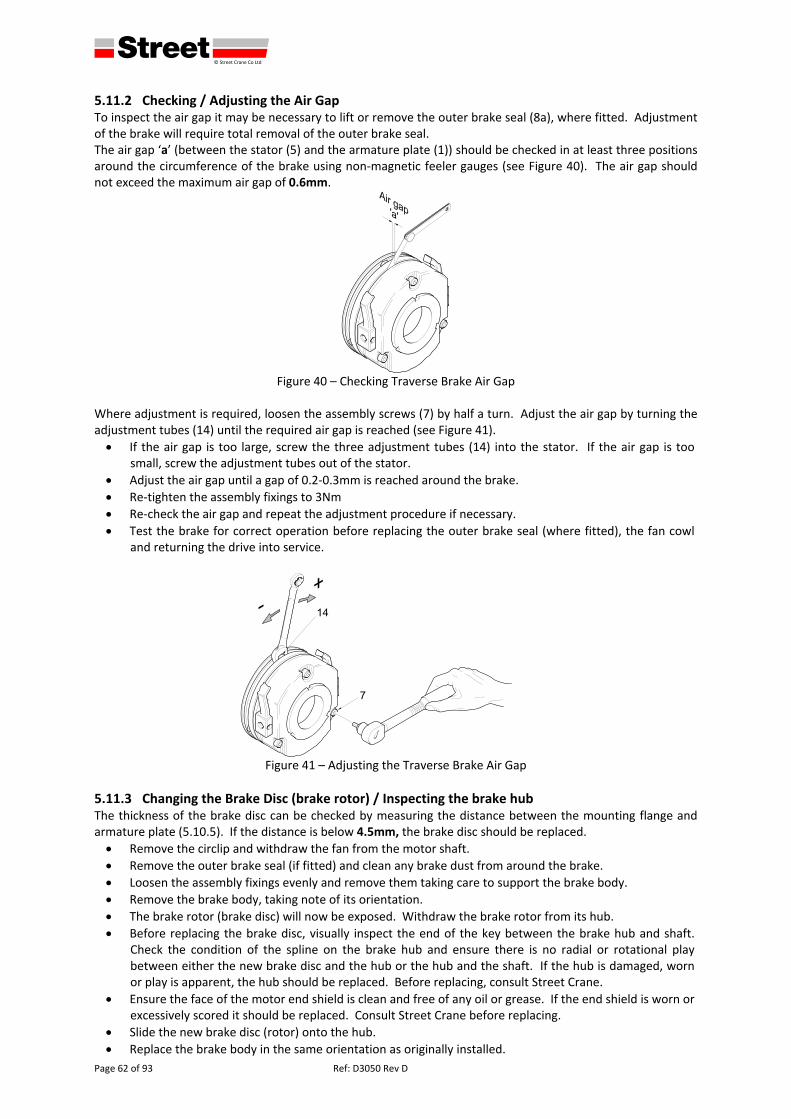
defgh © Street Crane Co Ltd
Page 62 of 93 Ref: D3050 Rev D
5.11.2 Checking / Adjusting the Air Gap To inspect the air gap it may be necessary to lift or remove the outer brake seal (8a), where fitted. Adjustment of the brake will require total removal of the outer brake seal. The air gap ‘a’ (between the stator (5) and the armature plate (1)) should be checked in at least three positions around the circumference of the brake using non‐magnetic feeler gauges (see Figure 40). The air gap should not exceed the maximum air gap of 0.6mm.
Figure 40 – Checking Traverse Brake Air Gap
Where adjustment is required, loosen the assembly screws (7) by half a turn. Adjust the air gap by turning the adjustment tubes (14) until the required air gap is reached (see Figure 41).
If the air gap is too large, screw the three adjustment tubes (14) into the stator. If the air gap is too small, screw the adjustment tubes out of the stator.
Adjust the air gap until a gap of 0.2‐0.3mm is reached around the brake.
Re‐tighten the assembly fixings to 3Nm
Re‐check the air gap and repeat the adjustment procedure if necessary.
Test the brake for correct operation before replacing the outer brake seal (where fitted), the fan cowl and returning the drive into service.
Figure 41 – Adjusting the Traverse Brake Air Gap
5.11.3 Changing the Brake Disc (brake rotor) / Inspecting the brake hub The thickness of the brake disc can be checked by measuring the distance between the mounting flange and armature plate (5.10.5). If the distance is below 4.5mm, the brake disc should be replaced.
Remove the circlip and withdraw the fan from the motor shaft.
Remove the outer brake seal (if fitted) and clean any brake dust from around the brake.
Loosen the assembly fixings evenly and remove them taking care to support the brake body.
Remove the brake body, taking note of its orientation.
The brake rotor (brake disc) will now be exposed. Withdraw the brake rotor from its hub.
Before replacing the brake disc, visually inspect the end of the key between the brake hub and shaft. Check the condition of the spline on the brake hub and ensure there is no radial or rotational play between either the new brake disc and the hub or the hub and the shaft. If the hub is damaged, worn or play is apparent, the hub should be replaced. Before replacing, consult Street Crane.
Ensure the face of the motor end shield is clean and free of any oil or grease. If the end shield is worn or excessively scored it should be replaced. Consult Street Crane before replacing.
Slide the new brake disc (rotor) onto the hub.
Replace the brake body in the same orientation as originally installed.
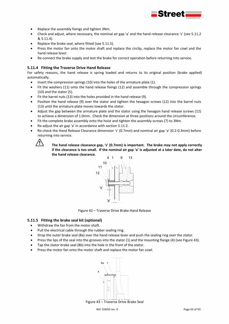
defgh © Street Crane Co Ltd
Ref: D3050 rev. D Page 63 of 93
Replace the assembly fixings and tighten 3Nm.
Check and adjust, where necessary, the nominal air gap ‘a’ and the hand release clearance ‘s’ (see 5.11.2 & 5.11.4).
Replace the brake seal, where fitted (see 5.11.5).
Press the motor fan onto the motor shaft and replace the circlip, replace the motor fan cowl and the hand release lever.
Re‐connect the brake supply and test the brake for correct operation before returning into service.
5.11.4 Fitting the Traverse Drive Hand Release For safety reasons, the hand release is spring loaded and returns to its original position (brake applied) automatically.
Insert the compression springs (10) into the holes of the armature plate (1).
Fit the washers (11) onto the hand release fixings (12) and assemble through the compression springs (10) and the stator (5).
Fit the barrel nuts (13) into the holes provided in the hand release (9).
Position the hand release (9) over the stator and tighten the hexagon screws (12) into the barrel nuts (13) until the armature plate moves towards the stator.
Adjust the gap between the armature plate and the stator using the hexagon hand release screws (12) to achieve a dimension of 1.0mm. Check the dimension at three positions around the circumference.
Fit the complete brake assembly onto the hoist and tighten the assembly screws (7) to 3Nm.
Re‐adjust the air gap ‘a’ in accordance with section 5.11.2.
Re‐check the Hand Release Clearance dimension ‘s’ (0.7mm) and nominal air gap ‘a’ (0.2‐0.3mm) before returning into service.
1 The hand release clearance gap, ‘s’ (0.7mm) is important. The brake may not apply correctly if the clearance is too small. If the nominal air gap ‘a’ is adjusted at a later date, do not alter the hand release clearance.
Figure 42 – Traverse Drive Brake Hand Release
5.11.5 Fitting the brake seal kit (optional) Withdraw the fan from the motor shaft.
Pull the electrical cable through the rubber sealing ring.
Drop the outer brake seal (8a) over the hand release lever and push the sealing ring over the stator.
Press the lips of the seal into the grooves into the stator (1) and the mounting flange (4) (see Figure 43).
Tap the stator brake seal (8b) into the hole in the front of the stator.
Press the motor fan onto the motor shaft and replace the motor fan cowl.
Figure 43 – Traverse Drive Brake Seal
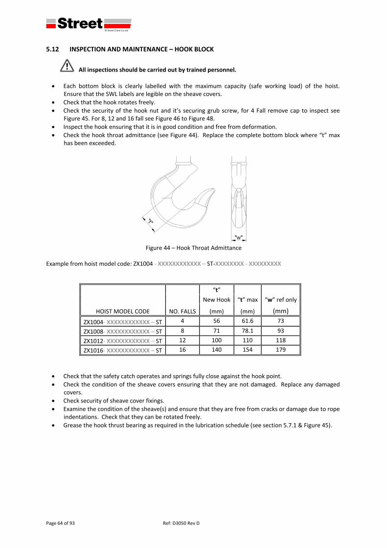
defgh © Street Crane Co Ltd
Page 64 of 93 Ref: D3050 Rev D
5.12 INSPECTION AND MAINTENANCE – HOOK BLOCK
1 All inspections should be carried out by trained personnel.
Each bottom block is clearly labelled with the maximum capacity (safe working load) of the hoist. Ensure that the SWL labels are legible on the sheave covers.
Check that the hook rotates freely.
Check the security of the hook nut and it’s securing grub screw, for 4 Fall remove cap to inspect see Figure 45. For 8, 12 and 16 fall see Figure 46 to Figure 48.
Inspect the hook ensuring that it is in good condition and free from deformation.
Check the hook throat admittance (see Figure 44). Replace the complete bottom block where “t” max has been exceeded.
Figure 44 – Hook Throat Admittance
Example from hoist model code: ZX1004 ‐ XXXXXXXXXXXX – ST‐XXXXXXXX ‐ XXXXXXXXX
HOIST MODEL CODE NO. FALLS
“t”
“w” ref only New Hook “t” max
(mm) (mm) (mm)
ZX1004‐ XXXXXXXXXXXX – ST 4 56 61.6 73
ZX1008‐ XXXXXXXXXXXX – ST 8 71 78.1 93
ZX1012‐ XXXXXXXXXXXX – ST 12 100 110 118
ZX1016‐ XXXXXXXXXXXX – ST 16 140 154 179
Check that the safety catch operates and springs fully close against the hook point.
Check the condition of the sheave covers ensuring that they are not damaged. Replace any damaged covers.
Check security of sheave cover fixings.
Examine the condition of the sheave(s) and ensure that they are free from cracks or damage due to rope indentations. Check that they can be rotated freely.
Grease the hook thrust bearing as required in the lubrication schedule (see section 5.7.1 & Figure 45).
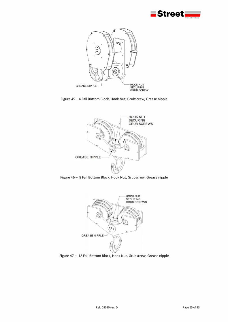
defgh © Street Crane Co Ltd
Ref: D3050 rev. D Page 65 of 93
Figure 45 – 4 Fall Bottom Block, Hook Nut, Grubscrew, Grease nipple
Figure 46 – 8 Fall Bottom Block, Hook Nut, Grubscrew, Grease nipple
Figure 47 – 12 Fall Bottom Block, Hook Nut, Grubscrew, Grease nipple

defgh © Street Crane Co Ltd
Page 66 of 93 Ref: D3050 Rev D
Figure 48 – 16 Fall Bottom Block, Hook Nut, Grubscrew, Grease nipple
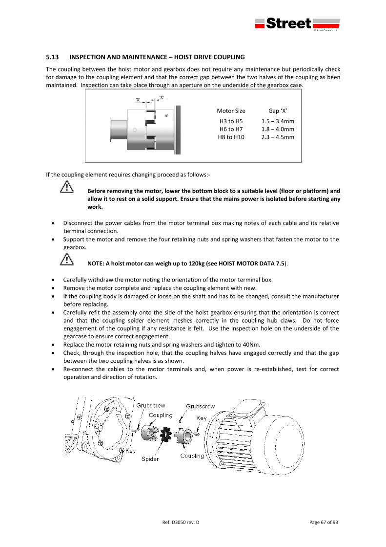
defgh © Street Crane Co Ltd
Ref: D3050 rev. D Page 67 of 93
5.13 INSPECTION AND MAINTENANCE – HOIST DRIVE COUPLING
The coupling between the hoist motor and gearbox does not require any maintenance but periodically check for damage to the coupling element and that the correct gap between the two halves of the coupling as been maintained. Inspection can take place through an aperture on the underside of the gearbox case.
Motor Size Gap ‘X’
H3 to H5 1.5 – 3.4mm H6 to H7 1.8 – 4.0mm H8 to H10 2.3 – 4.5mm
If the coupling element requires changing proceed as follows:‐
1 Before removing the motor, lower the bottom block to a suitable level (floor or platform) and allow it to rest on a solid support. Ensure that the mains power is isolated before starting any work.
Disconnect the power cables from the motor terminal box making notes of each cable and its relative terminal connection.
Support the motor and remove the four retaining nuts and spring washers that fasten the motor to the gearbox.
1 NOTE: A hoist motor can weigh up to 120kg (see HOIST MOTOR DATA 7.5).
Carefully withdraw the motor noting the orientation of the motor terminal box.
Remove the motor complete and replace the coupling element with new.
If the coupling body is damaged or loose on the shaft and has to be changed, consult the manufacturer before replacing.
Carefully refit the assembly onto the side of the hoist gearbox ensuring that the orientation is correct and that the coupling spider element meshes correctly in the coupling hub claws. Do not force engagement of the coupling if any resistance is felt. Use the inspection hole on the underside of the gearcase to ensure correct engagement.
Replace the motor retaining nuts and spring washers and tighten to 40Nm.
Check, through the inspection hole, that the coupling halves have engaged correctly and that the gap between the two coupling halves is as shown.
Re‐connect the cables to the motor terminals and, when power is re‐established, test for correct operation and direction of rotation.
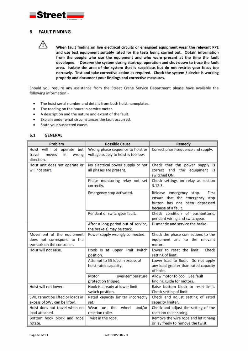
defgh © Street Crane Co Ltd
Page 68 of 93 Ref: D3050 Rev D
6 FAULT FINDING
1 When fault finding on live electrical circuits or energised equipment wear the relevant PPE and use test equipment suitably rated for the tests being carried out. Obtain information from the people who use the equipment and who were present at the time the fault developed. Observe the system during start‐up, operation and shut‐down to trace the fault area. Isolate the area of the system that is suspicious but do not restrict your focus too narrowly. Test and take corrective action as required. Check the system / device is working properly and document your findings and corrective measures.
Should you require any assistance from the Street Crane Service Department please have available the following information:‐
The hoist serial number and details from both hoist nameplates.
The reading on the hours‐in‐service meter.
A description and the nature and extent of the fault.
Explain under what circumstances the fault occurred.
State your suspected cause.
6.1 GENERAL
Problem Possible Cause Remedy
Hoist will not operate but travel moves in wrong direction.
Wrong phase sequence to hoist or voltage supply to hoist is too low.
Correct phase sequence and supply.
Hoist unit does not operate or will not start.
No electrical power supply or not all phases are present.
Check that the power supply is correct and the equipment is switched ON.
Phase monitoring relay not set correctly.
Check settings on relay as section 3.12.3.
Emergency stop activated. Release emergency stop. First ensure that the emergency stop button has not been depressed because of a fault.
Pendant or switchgear fault. Check condition of pushbuttons, pendant wiring and switchgear.
After a long period out of service, the brake(s) may be stuck.
Dismantle and service the brake.
Movement of the equipment does not correspond to the symbols on the controller.
Power supply wrongly connected. Check the phase connections to the equipment and to the relevant motor.
Hoist will not raise. Hook is at upper limit switch position.
Lower to reset the limit. Check setting of limit.
Attempt to lift load in excess of hoist rated capacity.
Lower load to floor. Do not apply any load greater than rated capacity of hoist.
Motor over‐temperature protection tripped.
Allow motor to cool. See fault finding guide for motors.
Hoist will not lower. Hook is already at lower limit switch position.
Raise bottom block to reset limit. Check setting of limit
SWL cannot be lifted or loads in excess of SWL can be lifted.
Rated capacity limiter incorrectly set.
Check and adjust setting of rated capacity limiter.
Hoist does not travel when no load attached.
Wear on the wheel and/or reaction roller.
Check and adjust the setting of the reaction roller spring.
Bottom hook block and rope rotate.
Twist in the rope. Remove the wire rope and let it hang or lay freely to remove the twist.
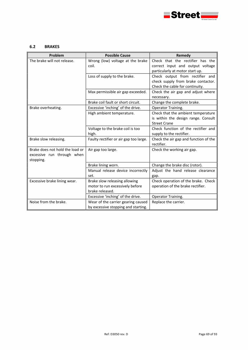
defgh © Street Crane Co Ltd
Ref: D3050 rev. D Page 69 of 93
6.2 BRAKES
Problem Possible Cause Remedy
The brake will not release. Wrong (low) voltage at the brake coil.
Check that the rectifier has the correct input and output voltage particularly at motor start up.
Loss of supply to the brake. Check output from rectifier and check supply from brake contactor. Check the cable for continuity.
Max permissible air gap exceeded. Check the air gap and adjust where necessary.
Brake coil fault or short circuit. Change the complete brake.
Brake overheating. Excessive ‘inching’ of the drive. Operator Training.
High ambient temperature. Check that the ambient temperature is within the design range. Consult Street Crane
Voltage to the brake coil is too high.
Check function of the rectifier and supply to the rectifier.
Brake slow releasing. Faulty rectifier or air gap too large. Check the air gap and function of the rectifier.
Brake does not hold the load or excessive run through when stopping.
Air gap too large. Check the working air gap.
Brake lining worn. Change the brake disc (rotor).
Manual release device incorrectly set.
Adjust the hand release clearance gap.
Excessive brake lining wear. Brake slow releasing allowing motor to run excessively before brake released.
Check operation of the brake. Check operation of the brake rectifier.
Excessive ‘inching’ of the drive. Operator Training.
Noise from the brake. Wear of the carrier gearing caused by excessive stopping and starting.
Replace the carrier.
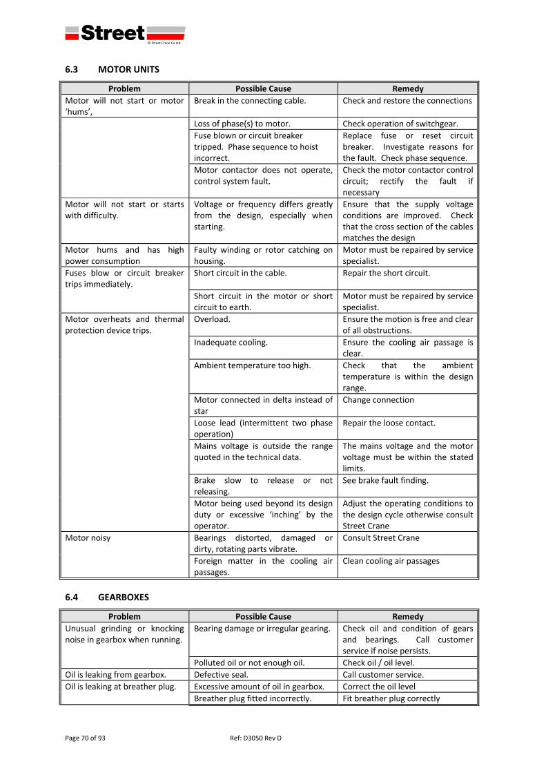
defgh © Street Crane Co Ltd
Page 70 of 93 Ref: D3050 Rev D
6.3 MOTOR UNITS
Problem Possible Cause Remedy
Motor will not start or motor ‘hums’,
Break in the connecting cable. Check and restore the connections
Loss of phase(s) to motor. Check operation of switchgear.
Fuse blown or circuit breaker tripped. Phase sequence to hoist incorrect.
Replace fuse or reset circuit breaker. Investigate reasons for the fault. Check phase sequence.
Motor contactor does not operate, control system fault.
Check the motor contactor control circuit; rectify the fault if necessary
Motor will not start or starts with difficulty.
Voltage or frequency differs greatly from the design, especially when starting.
Ensure that the supply voltage conditions are improved. Check that the cross section of the cables matches the design
Motor hums and has high power consumption
Faulty winding or rotor catching on housing.
Motor must be repaired by service specialist.
Fuses blow or circuit breaker trips immediately.
Short circuit in the cable. Repair the short circuit.
Short circuit in the motor or short circuit to earth.
Motor must be repaired by service specialist.
Motor overheats and thermal protection device trips.
Overload. Ensure the motion is free and clear of all obstructions.
Inadequate cooling. Ensure the cooling air passage is clear.
Ambient temperature too high. Check that the ambient temperature is within the design range.
Motor connected in delta instead of star
Change connection
Loose lead (intermittent two phase operation)
Repair the loose contact.
Mains voltage is outside the range quoted in the technical data.
The mains voltage and the motor voltage must be within the stated limits.
Brake slow to release or not releasing.
See brake fault finding.
Motor being used beyond its design duty or excessive ‘inching’ by the operator.
Adjust the operating conditions to the design cycle otherwise consult Street Crane
Motor noisy Bearings distorted, damaged or dirty, rotating parts vibrate.
Consult Street Crane
Foreign matter in the cooling air passages.
Clean cooling air passages
6.4 GEARBOXES
Problem Possible Cause Remedy
Unusual grinding or knocking noise in gearbox when running.
Bearing damage or irregular gearing. Check oil and condition of gears and bearings. Call customer service if noise persists.
Polluted oil or not enough oil. Check oil / oil level.
Oil is leaking from gearbox. Defective seal. Call customer service.
Oil is leaking at breather plug. Excessive amount of oil in gearbox. Correct the oil level
Breather plug fitted incorrectly. Fit breather plug correctly
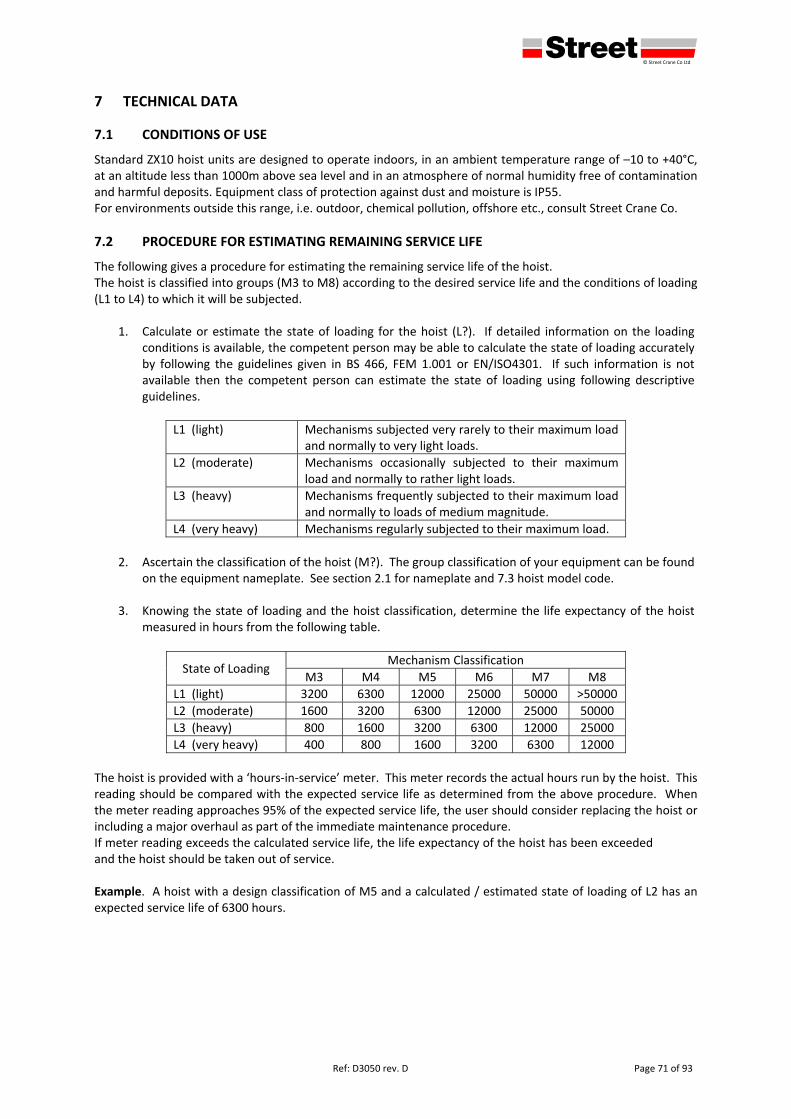
defgh © Street Crane Co Ltd
Ref: D3050 rev. D Page 71 of 93
7 TECHNICAL DATA
7.1 CONDITIONS OF USE
Standard ZX10 hoist units are designed to operate indoors, in an ambient temperature range of –10 to +40°C, at an altitude less than 1000m above sea level and in an atmosphere of normal humidity free of contamination and harmful deposits. Equipment class of protection against dust and moisture is IP55. For environments outside this range, i.e. outdoor, chemical pollution, offshore etc., consult Street Crane Co.
7.2 PROCEDURE FOR ESTIMATING REMAINING SERVICE LIFE
The following gives a procedure for estimating the remaining service life of the hoist. The hoist is classified into groups (M3 to M8) according to the desired service life and the conditions of loading (L1 to L4) to which it will be subjected.
1. Calculate or estimate the state of loading for the hoist (L?). If detailed information on the loading conditions is available, the competent person may be able to calculate the state of loading accurately by following the guidelines given in BS 466, FEM 1.001 or EN/ISO4301. If such information is not available then the competent person can estimate the state of loading using following descriptive guidelines.
L1 (light) Mechanisms subjected very rarely to their maximum load and normally to very light loads.
L2 (moderate) Mechanisms occasionally subjected to their maximum load and normally to rather light loads.
L3 (heavy) Mechanisms frequently subjected to their maximum load and normally to loads of medium magnitude.
L4 (very heavy) Mechanisms regularly subjected to their maximum load.
2. Ascertain the classification of the hoist (M?). The group classification of your equipment can be found
on the equipment nameplate. See section 2.1 for nameplate and 7.3 hoist model code.
3. Knowing the state of loading and the hoist classification, determine the life expectancy of the hoist measured in hours from the following table.
State of Loading Mechanism Classification
M3 M4 M5 M6 M7 M8
L1 (light) 3200 6300 12000 25000 50000 >50000
L2 (moderate) 1600 3200 6300 12000 25000 50000
L3 (heavy) 800 1600 3200 6300 12000 25000
L4 (very heavy) 400 800 1600 3200 6300 12000
The hoist is provided with a ‘hours‐in‐service’ meter. This meter records the actual hours run by the hoist. This reading should be compared with the expected service life as determined from the above procedure. When the meter reading approaches 95% of the expected service life, the user should consider replacing the hoist or including a major overhaul as part of the immediate maintenance procedure. If meter reading exceeds the calculated service life, the life expectancy of the hoist has been exceeded and the hoist should be taken out of service. Example. A hoist with a design classification of M5 and a calculated / estimated state of loading of L2 has an expected service life of 6300 hours.
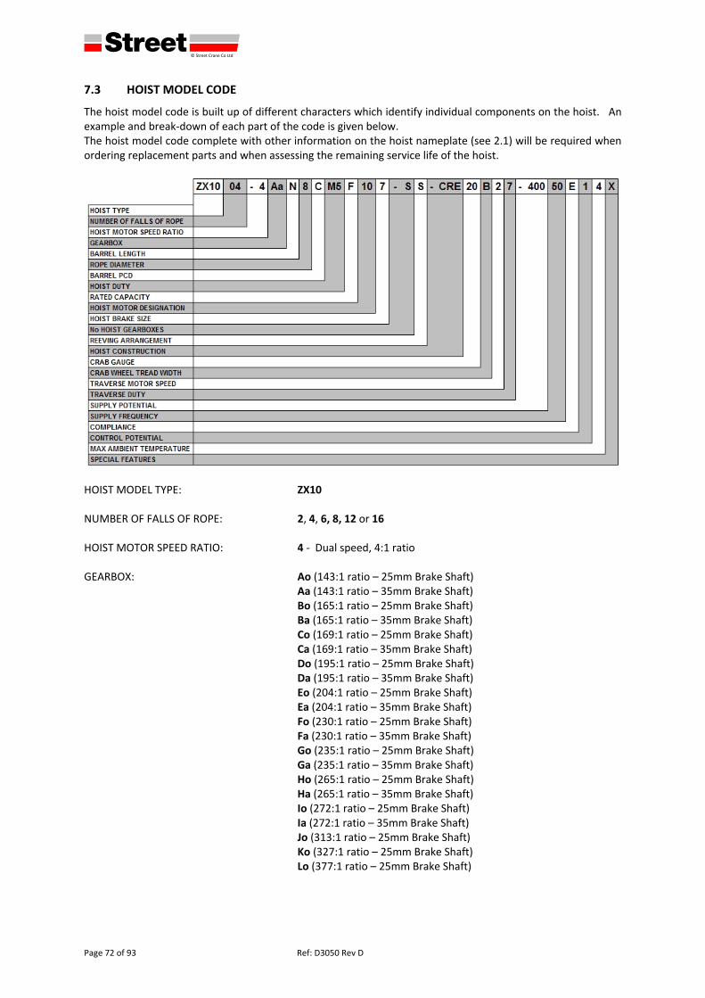
defgh © Street Crane Co Ltd
Page 72 of 93 Ref: D3050 Rev D
7.3 HOIST MODEL CODE
The hoist model code is built up of different characters which identify individual components on the hoist. An example and break‐down of each part of the code is given below. The hoist model code complete with other information on the hoist nameplate (see 2.1) will be required when ordering replacement parts and when assessing the remaining service life of the hoist.
HOIST MODEL TYPE: ZX10 NUMBER OF FALLS OF ROPE: 2, 4, 6, 8, 12 or 16 HOIST MOTOR SPEED RATIO: 4 ‐ Dual speed, 4:1 ratio GEARBOX: Ao (143:1 ratio – 25mm Brake Shaft) Aa (143:1 ratio – 35mm Brake Shaft) Bo (165:1 ratio – 25mm Brake Shaft) Ba (165:1 ratio – 35mm Brake Shaft) Co (169:1 ratio – 25mm Brake Shaft) Ca (169:1 ratio – 35mm Brake Shaft) Do (195:1 ratio – 25mm Brake Shaft) Da (195:1 ratio – 35mm Brake Shaft) Eo (204:1 ratio – 25mm Brake Shaft) Ea (204:1 ratio – 35mm Brake Shaft) Fo (230:1 ratio – 25mm Brake Shaft) Fa (230:1 ratio – 35mm Brake Shaft) Go (235:1 ratio – 25mm Brake Shaft) Ga (235:1 ratio – 35mm Brake Shaft) Ho (265:1 ratio – 25mm Brake Shaft) Ha (265:1 ratio – 35mm Brake Shaft) Io (272:1 ratio – 25mm Brake Shaft) Ia (272:1 ratio – 35mm Brake Shaft) Jo (313:1 ratio – 25mm Brake Shaft) Ko (327:1 ratio – 25mm Brake Shaft) Lo (377:1 ratio – 25mm Brake Shaft)
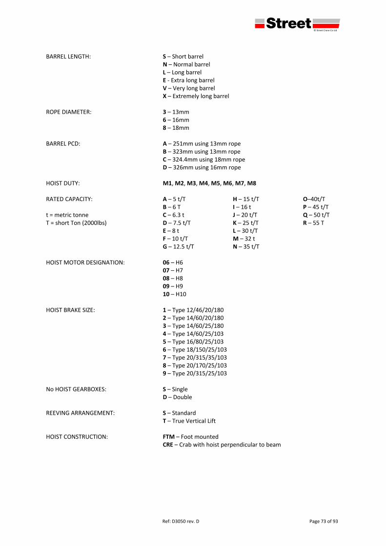
defgh © Street Crane Co Ltd
Ref: D3050 rev. D Page 73 of 93
BARREL LENGTH: S – Short barrel N – Normal barrel
L – Long barrel E ‐ Extra long barrel V – Very long barrel X – Extremely long barrel
ROPE DIAMETER: 3 – 13mm 6 – 16mm 8 – 18mm BARREL PCD: A – 251mm using 13mm rope B – 323mm using 13mm rope C – 324.4mm using 18mm rope D – 326mm using 16mm rope HOIST DUTY: M1, M2, M3, M4, M5, M6, M7, M8 RATED CAPACITY: A – 5 t/T H – 15 t/T O–40t/T B – 6 T I – 16 t P – 45 t/T t = metric tonne C – 6.3 t J – 20 t/T Q – 50 t/T T = short Ton (2000lbs) D – 7.5 t/T K – 25 t/T R – 55 T E – 8 t L – 30 t/T F – 10 t/T M – 32 t G – 12.5 t/T N – 35 t/T HOIST MOTOR DESIGNATION: 06 – H6 07 – H7 08 – H8 09 – H9 10 – H10 HOIST BRAKE SIZE: 1 – Type 12/46/20/180
2 – Type 14/60/20/180 3 – Type 14/60/25/180 4 – Type 14/60/25/103 5 – Type 16/80/25/103 6 – Type 18/150/25/103 7 – Type 20/315/35/103 8 – Type 20/170/25/103 9 – Type 20/315/25/103
No HOIST GEARBOXES: S – Single D – Double REEVING ARRANGEMENT: S – Standard T – True Vertical Lift HOIST CONSTRUCTION: FTM – Foot mounted CRE – Crab with hoist perpendicular to beam
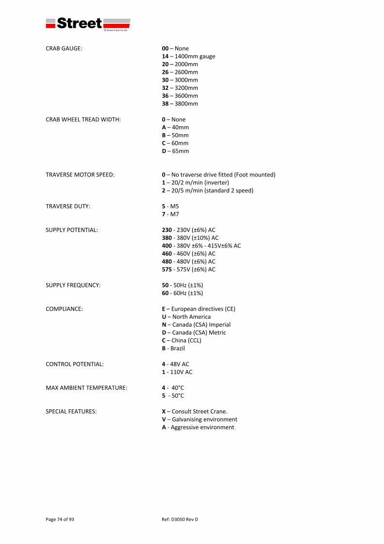
defgh © Street Crane Co Ltd
Page 74 of 93 Ref: D3050 Rev D
CRAB GAUGE: 00 – None 14 – 1400mm gauge 20 – 2000mm 26 – 2600mm 30 – 3000mm 32 – 3200mm
36 – 3600mm 38 – 3800mm CRAB WHEEL TREAD WIDTH: 0 – None A – 40mm B – 50mm C – 60mm D – 65mm TRAVERSE MOTOR SPEED: 0 – No traverse drive fitted (Foot mounted)
1 – 20/2 m/min (inverter) 2 – 20/5 m/min (standard 2 speed) TRAVERSE DUTY: 5 ‐ M5
7 ‐ M7 SUPPLY POTENTIAL: 230 ‐ 230V (±6%) AC 380 ‐ 380V (±10%) AC 400 ‐ 380V ±6% ‐ 415V±6% AC 460 ‐ 460V (±6%) AC 480 ‐ 480V (±6%) AC 575 ‐ 575V (±6%) AC SUPPLY FREQUENCY: 50 ‐ 50Hz (±1%) 60 ‐ 60Hz (±1%) COMPLIANCE: E – European directives (CE) U – North America N – Canada (CSA) Imperial D – Canada (CSA) Metric C – China (CCL) B ‐ Brazil CONTROL POTENTIAL: 4 ‐ 48V AC 1 ‐ 110V AC MAX AMBIENT TEMPERATURE: 4 ‐ 40°C 5 ‐ 50°C SPECIAL FEATURES: X – Consult Street Crane. V – Galvanising environment A ‐ Aggressive environment
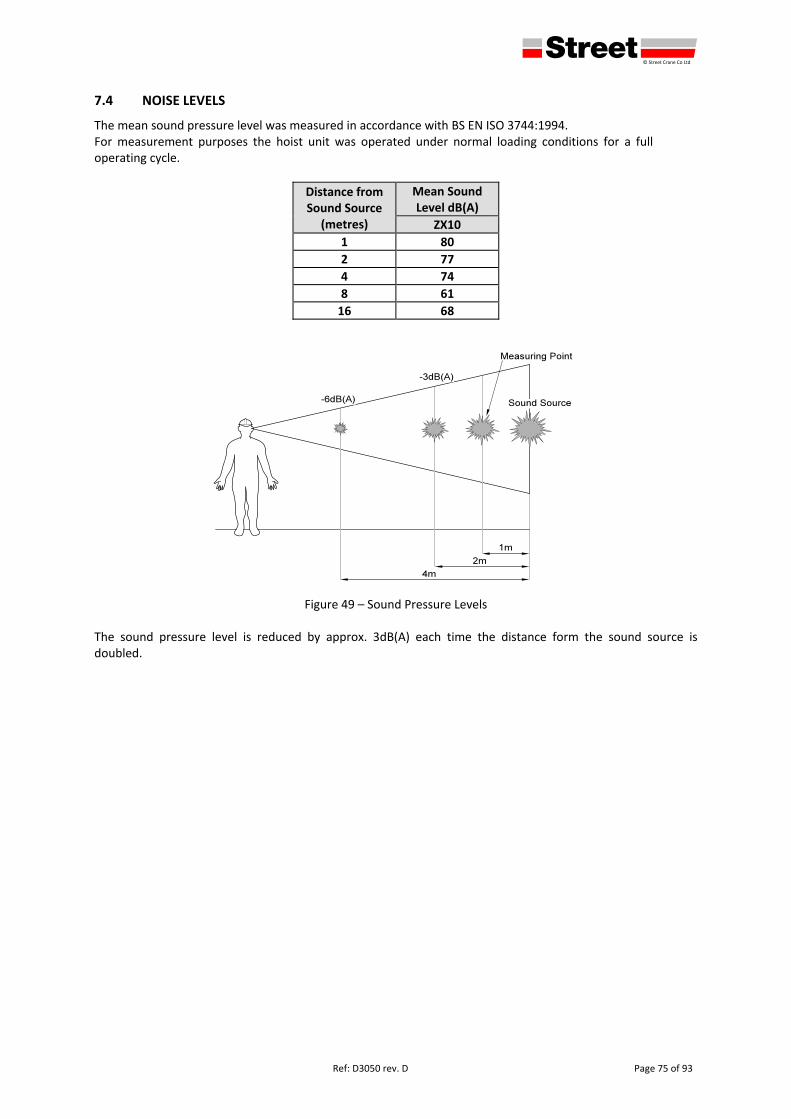
defgh © Street Crane Co Ltd
Ref: D3050 rev. D Page 75 of 93
7.4 NOISE LEVELS
The mean sound pressure level was measured in accordance with BS EN ISO 3744:1994. For measurement purposes the hoist unit was operated under normal loading conditions for a full operating cycle.
Distance from Sound Source
(metres)
Mean Sound Level dB(A)
ZX10
1 80
2 77
4 74
8 61
16 68
Figure 49 – Sound Pressure Levels The sound pressure level is reduced by approx. 3dB(A) each time the distance form the sound source is doubled.
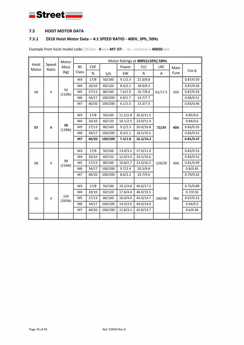
defgh © Street Crane Co Ltd
Page 76 of 93 Ref: D3050 Rev D
7.5 HOIST MOTOR DATA
7.5.1 ZX10 Hoist Motor Data – 4:1 SPEED RATIO ‐ 400V, 3Ph, 50Hz Example from hoist model code: ZX10xx ‐ 4xxxxxM7x07x – xx ‐ xxxxxxxx – 40050xxxx
Hoist Motor
Speed Ratio
Motor Mass (kg)
Motor Ratings at 400V(±10%) 50Hz
BS Class
CDF
S/h
Power FLC LRC Main Fuse
Cos % kW A A
06 4 50
(110lb)
M3 17/8 50/100 9.1/2.3 21.0/8.8
61/17.5 32A
0.87/0.59
M4 20/10 60/120 8.4/2.1 18.9/8.3 0.87/0.56
M5 27/13 80/160 7.6/1.9 16.7/8.0 0.87/0.54
M6 34/17 100/200 6.8/1.7 14.7/7.7 0.84/0.51
M7 40/20 100/200 6.1/1.5 13.3/7.5 0.83/0.46
07 4 58
(128lb)
M3 17/8 50/100 11.2/2.8 26.0/11.5
72/24 40A
0.85/0.6
M4 20/10 60/120 10.1/2.5 23.0/11.4 0.84/0.6
M5 27/13 80/160 9.2/2.3 20.0/10.8 0.83/0.55
M6 34/17 100/200 8.3/2.1 18.5/10.5 0.83/0.52
M7 40/20 100/200 7.4/1.8 16.3/10.2 0.81/0.47
08 4 98
(216lb)
M3 17/8 50/100 13.0/3.2 27.0/11.0
129/29 40A
0.83/0.53
M4 20/10 60/120 12.0/3.0 24.5/10.6 0.83/0.52
M5 27/13 80/160 10.8/2.7 22.0/10.2 0.81/0.49
M6 34/17 100/200 9.7/2.4 20.3/9.8 0.8/0.45
M7 40/20 100/200 8.6/2.2 19.7/9.6 0.79/0.42
10 4 120
(265lb)
M3 17/8 50/100 19.2/4.8 46.0/17.5
240/40 TBA
0.75/0.89
M4 20/10 60/120 17.6/4.4 46.0/15.5 0.7/0.56
M5 27/13 80/160 16.0/4.0 45.0/14.7 0.67/0.53
M6 34/17 100/200 14.4/3.6 44.0/14.0 0.64/0.5
M7 40/20 100/200 12.8/3.2 42.0/13.7 0.6/0.46
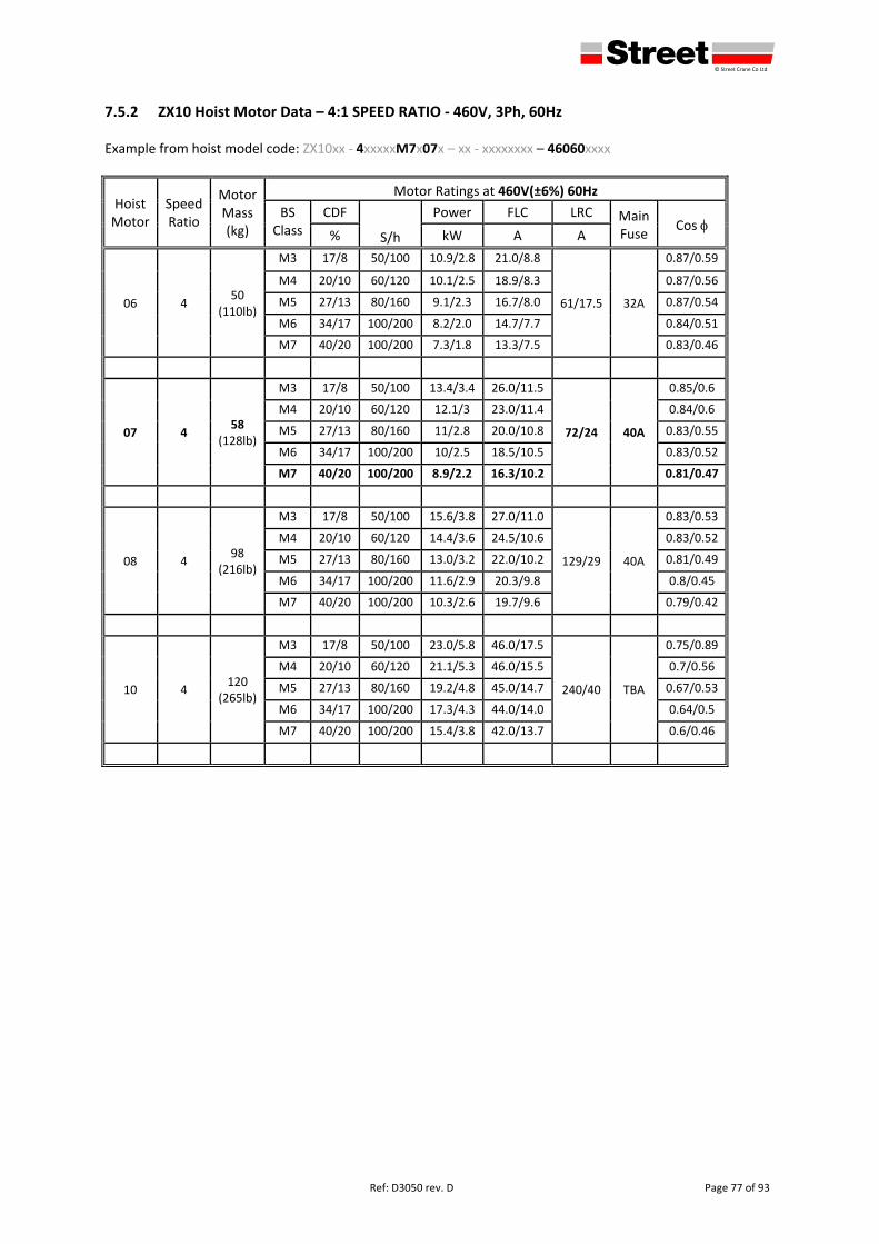
defgh © Street Crane Co Ltd
Ref: D3050 rev. D Page 77 of 93
7.5.2 ZX10 Hoist Motor Data – 4:1 SPEED RATIO ‐ 460V, 3Ph, 60Hz Example from hoist model code: ZX10xx ‐ 4xxxxxM7x07x – xx ‐ xxxxxxxx – 46060xxxx
Hoist Motor
Speed Ratio
Motor Mass (kg)
Motor Ratings at 460V(±6%) 60Hz
BS Class
CDF
S/h
Power FLC LRC Main Fuse
Cos % kW A A
06 4 50
(110lb)
M3 17/8 50/100 10.9/2.8 21.0/8.8
61/17.5 32A
0.87/0.59
M4 20/10 60/120 10.1/2.5 18.9/8.3 0.87/0.56
M5 27/13 80/160 9.1/2.3 16.7/8.0 0.87/0.54
M6 34/17 100/200 8.2/2.0 14.7/7.7 0.84/0.51
M7 40/20 100/200 7.3/1.8 13.3/7.5 0.83/0.46
07 4 58
(128lb)
M3 17/8 50/100 13.4/3.4 26.0/11.5
72/24 40A
0.85/0.6
M4 20/10 60/120 12.1/3 23.0/11.4 0.84/0.6
M5 27/13 80/160 11/2.8 20.0/10.8 0.83/0.55
M6 34/17 100/200 10/2.5 18.5/10.5 0.83/0.52
M7 40/20 100/200 8.9/2.2 16.3/10.2 0.81/0.47
08 4 98
(216lb)
M3 17/8 50/100 15.6/3.8 27.0/11.0
129/29 40A
0.83/0.53
M4 20/10 60/120 14.4/3.6 24.5/10.6 0.83/0.52
M5 27/13 80/160 13.0/3.2 22.0/10.2 0.81/0.49
M6 34/17 100/200 11.6/2.9 20.3/9.8 0.8/0.45
M7 40/20 100/200 10.3/2.6 19.7/9.6 0.79/0.42
10 4 120
(265lb)
M3 17/8 50/100 23.0/5.8 46.0/17.5
240/40 TBA
0.75/0.89
M4 20/10 60/120 21.1/5.3 46.0/15.5 0.7/0.56
M5 27/13 80/160 19.2/4.8 45.0/14.7 0.67/0.53
M6 34/17 100/200 17.3/4.3 44.0/14.0 0.64/0.5
M7 40/20 100/200 15.4/3.8 42.0/13.7 0.6/0.46
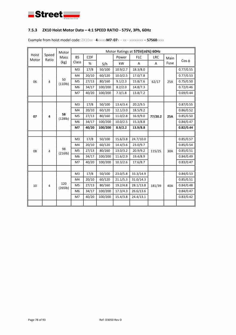
defgh © Street Crane Co Ltd
Page 78 of 93 Ref: D3050 Rev D
7.5.3 ZX10 Hoist Motor Data – 4:1 SPEED RATIO ‐ 575V, 3Ph, 60Hz Example from hoist model code: ZX10xx ‐ 4xxxxxM7x07x – xx ‐ xxxxxxxx – 57560xxxx
Hoist Motor
Speed Ratio
Motor Mass (kg)
Motor Ratings at 575V(±6%) 60Hz
BS Class
CDF
S/h
Power FLC LRC Main Fuse
Cos % kW A A
06 4 50
(110lb)
M3 17/8 50/100 10.9/2.7 18.3/8.0
62/17 25A
0.77/0.55
M4 20/10 60/120 10.0/2.5 17.0/7.8 0.77/0.53
M5 27/13 80/160 9.1/2.3 15.8/7.6 0.75/0.50
M6 34/17 100/200 8.2/2.0 14.8/7.3 0.72/0.46
M7 40/20 100/200 7.3/1.8 13.8/7.2 0.69/0.44
07 4 58
(128lb)
M3 17/8 50/100 13.4/3.4 20.2/9.5
77/20.2 25A
0.87/0.55
M4 20/10 60/120 12.1/3.0 18.5/9.2 0.86/0.52
M5 27/13 80/160 11.0/2.8 16.9/9.0 0.85/0.50
M6 34/17 100/200 10.0/2.5 15.3/8.8 0.84/0.47
M7 40/20 100/200 8.9/2.2 13.9/8.8 0.82/0.44
08 4 98
(216lb)
M3 17/8 50/100 15.6/3.8 24.7/10.0
115/25 30A
0.85/0.57
M4 20/10 60/120 14.4/3.6 23.0/9.7 0.85/0.54
M5 27/13 80/160 13.0/3.2 20.9/9.2 0.85/0.51
M6 34/17 100/200 11.6/2.9 19.4/8.9 0.84/0.49
M7 40/20 100/200 10.3/2.6 17.6/8.7 0.83/0.47
10 4 120
(265lb)
M3 17/8 50/100 23.0/5.8 33.3/14.9
181/39 40A
0.84/0.53
M4 20/10 60/120 21.1/5.3 31.0/14.3 0.85/0.51
M5 27/13 80/160 19.2/4.8 28.1/13.8 0.84/0.48
M6 34/17 100/200 17.3/4.3 26.6/13.6 0.84/0.47
M7 40/20 100/200 15.4/3.8 24.4/13.1 0.83/0.42
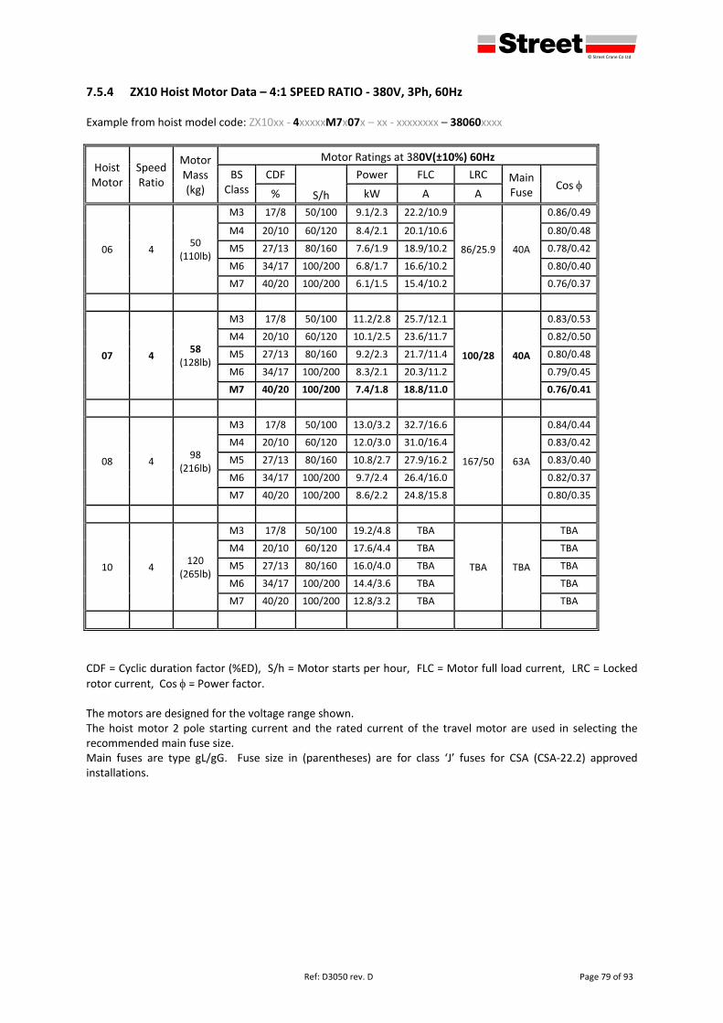
defgh © Street Crane Co Ltd
Ref: D3050 rev. D Page 79 of 93
7.5.4 ZX10 Hoist Motor Data – 4:1 SPEED RATIO ‐ 380V, 3Ph, 60Hz Example from hoist model code: ZX10xx ‐ 4xxxxxM7x07x – xx ‐ xxxxxxxx – 38060xxxx
Hoist Motor
Speed Ratio
Motor Mass (kg)
Motor Ratings at 380V(±10%) 60Hz
BS Class
CDF
S/h
Power FLC LRC Main Fuse
Cos % kW A A
06 4 50
(110lb)
M3 17/8 50/100 9.1/2.3 22.2/10.9
86/25.9 40A
0.86/0.49
M4 20/10 60/120 8.4/2.1 20.1/10.6 0.80/0.48
M5 27/13 80/160 7.6/1.9 18.9/10.2 0.78/0.42
M6 34/17 100/200 6.8/1.7 16.6/10.2 0.80/0.40
M7 40/20 100/200 6.1/1.5 15.4/10.2 0.76/0.37
07 4 58
(128lb)
M3 17/8 50/100 11.2/2.8 25.7/12.1
100/28 40A
0.83/0.53
M4 20/10 60/120 10.1/2.5 23.6/11.7 0.82/0.50
M5 27/13 80/160 9.2/2.3 21.7/11.4 0.80/0.48
M6 34/17 100/200 8.3/2.1 20.3/11.2 0.79/0.45
M7 40/20 100/200 7.4/1.8 18.8/11.0 0.76/0.41
08 4 98
(216lb)
M3 17/8 50/100 13.0/3.2 32.7/16.6
167/50 63A
0.84/0.44
M4 20/10 60/120 12.0/3.0 31.0/16.4 0.83/0.42
M5 27/13 80/160 10.8/2.7 27.9/16.2 0.83/0.40
M6 34/17 100/200 9.7/2.4 26.4/16.0 0.82/0.37
M7 40/20 100/200 8.6/2.2 24.8/15.8 0.80/0.35
10 4 120
(265lb)
M3 17/8 50/100 19.2/4.8 TBA
TBA TBA
TBA
M4 20/10 60/120 17.6/4.4 TBA TBA
M5 27/13 80/160 16.0/4.0 TBA TBA
M6 34/17 100/200 14.4/3.6 TBA TBA
M7 40/20 100/200 12.8/3.2 TBA TBA
CDF = Cyclic duration factor (%ED), S/h = Motor starts per hour, FLC = Motor full load current, LRC = Locked
rotor current, Cos = Power factor. The motors are designed for the voltage range shown. The hoist motor 2 pole starting current and the rated current of the travel motor are used in selecting the recommended main fuse size. Main fuses are type gL/gG. Fuse size in (parentheses) are for class ‘J’ fuses for CSA (CSA‐22.2) approved installations.
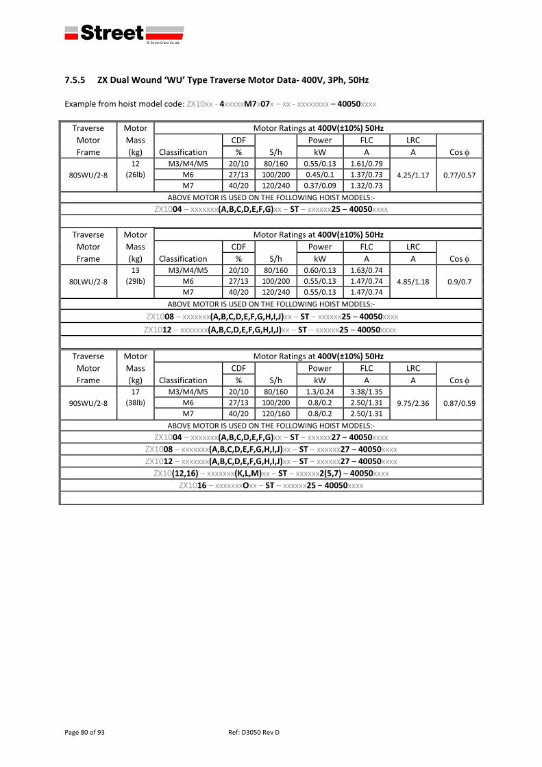
defgh © Street Crane Co Ltd
Page 80 of 93 Ref: D3050 Rev D
7.5.5 ZX Dual Wound ‘WU’ Type Traverse Motor Data‐ 400V, 3Ph, 50Hz Example from hoist model code: ZX10xx ‐ 4xxxxxM7x07x – xx ‐ xxxxxxxx – 40050xxxx
Traverse Motor Motor Ratings at 400V(±10%) 50Hz
Motor Mass
Classification
CDF
S/h
Power FLC LRC
Cos Frame (kg) % kW A A
80SWU/2‐8
12 M3/M4/M5 20/10 80/160 0.55/0.13 1.61/0.79
4.25/1.17 0.77/0.57 (26lb) M6 27/13 100/200 0.45/0.1 1.37/0.73
M7 40/20 120/240 0.37/0.09 1.32/0.73
ABOVE MOTOR IS USED ON THE FOLLOWING HOIST MODELS:‐
ZX1004 – xxxxxxx(A,B,C,D,E,F,G)xx – ST – xxxxxx25 – 40050xxxx
Traverse Motor Motor Ratings at 400V(±10%) 50Hz
Motor Mass
Classification
CDF
S/h
Power FLC LRC
Cos Frame (kg) % kW A A
80LWU/2‐8
13 M3/M4/M5 20/10 80/160 0.60/0.13 1.63/0.74
4.85/1.18 0.9/0.7 (29lb) M6 27/13 100/200 0.55/0.13 1.47/0.74
M7 40/20 120/240 0.55/0.13 1.47/0.74
ABOVE MOTOR IS USED ON THE FOLLOWING HOIST MODELS:‐
ZX1008 – xxxxxxx(A,B,C,D,E,F,G,H,I,J)xx – ST – xxxxxx25 – 40050xxxx
ZX1012 – xxxxxxx(A,B,C,D,E,F,G,H,I,J)xx – ST – xxxxxx25 – 40050xxxx
Traverse Motor Motor Ratings at 400V(±10%) 50Hz
Motor Mass
Classification
CDF
S/h
Power FLC LRC
Cos Frame (kg) % kW A A
90SWU/2‐8
17 M3/M4/M5 20/10 80/160 1.3/0.24 3.38/1.35
9.75/2.36 0.87/0.59 (38lb) M6 27/13 100/200 0.8/0.2 2.50/1.31
M7 40/20 120/160 0.8/0.2 2.50/1.31
ABOVE MOTOR IS USED ON THE FOLLOWING HOIST MODELS:‐
ZX1004 – xxxxxxx(A,B,C,D,E,F,G)xx – ST – xxxxxx27 – 40050xxxx ZX1008 – xxxxxxx(A,B,C,D,E,F,G,H,I,J)xx – ST – xxxxxx27 – 40050xxxx ZX1012 – xxxxxxx(A,B,C,D,E,F,G,H,I,J)xx – ST – xxxxxx27 – 40050xxxx ZX10(12,16) – xxxxxxx(K,L,M)xx – ST – xxxxxx2(5,7) – 40050xxxx
ZX1016 – xxxxxxxOxx – ST – xxxxxx25 – 40050xxxx
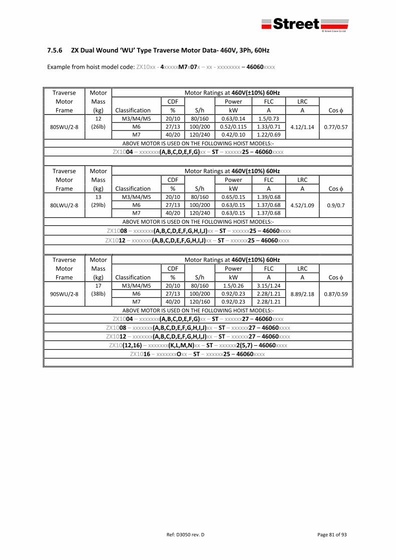
defgh © Street Crane Co Ltd
Ref: D3050 rev. D Page 81 of 93
7.5.6 ZX Dual Wound ‘WU’ Type Traverse Motor Data‐ 460V, 3Ph, 60Hz Example from hoist model code: ZX10xx ‐ 4xxxxxM7x07x – xx ‐ xxxxxxxx – 46060xxxx
Traverse Motor Motor Ratings at 460V(±10%) 60Hz
Motor Mass
Classification
CDF
S/h
Power FLC LRC
Cos Frame (kg) % kW A A
80SWU/2‐8
12 M3/M4/M5 20/10 80/160 0.63/0.14 1.5/0.73
4.12/1.14 0.77/0.57 (26lb) M6 27/13 100/200 0.52/0.115 1.33/0.71
M7 40/20 120/240 0.42/0.10 1.22/0.69
ABOVE MOTOR IS USED ON THE FOLLOWING HOIST MODELS:‐
ZX1004 – xxxxxxx(A,B,C,D,E,F,G)xx – ST – xxxxxx25 – 46060xxxx
Traverse Motor Motor Ratings at 460V(±10%) 60Hz
Motor Mass
Classification
CDF
S/h
Power FLC LRC
Cos Frame (kg) % kW A A
80LWU/2‐8
13 M3/M4/M5 20/10 80/160 0.65/0.15 1.39/0.68
4.52/1.09 0.9/0.7 (29lb) M6 27/13 100/200 0.63/0.15 1.37/0.68
M7 40/20 120/240 0.63/0.15 1.37/0.68
ABOVE MOTOR IS USED ON THE FOLLOWING HOIST MODELS:‐
ZX1008 – xxxxxxx(A,B,C,D,E,F,G,H,I,J)xx – ST – xxxxxx25 – 46060xxxx
ZX1012 – xxxxxxx(A,B,C,D,E,F,G,H,I,J)xx – ST – xxxxxx25 – 46060xxxx
Traverse Motor Motor Ratings at 460V(±10%) 60Hz
Motor Mass
Classification
CDF
S/h
Power FLC LRC
Cos Frame (kg) % kW A A
90SWU/2‐8
17 M3/M4/M5 20/10 80/160 1.5/0.26 3.15/1.24
8.89/2.18 0.87/0.59 (38lb) M6 27/13 100/200 0.92/0.23 2.28/1.21
M7 40/20 120/160 0.92/0.23 2.28/1.21
ABOVE MOTOR IS USED ON THE FOLLOWING HOIST MODELS:‐
ZX1004 – xxxxxxx(A,B,C,D,E,F,G)xx – ST – xxxxxx27 – 46060xxxx ZX1008 – xxxxxxx(A,B,C,D,E,F,G,H,I,J)xx – ST – xxxxxx27 – 46060xxxx ZX1012 – xxxxxxx(A,B,C,D,E,F,G,H,I,J)xx – ST – xxxxxx27 – 46060xxxx ZX10(12,16) – xxxxxxx(K,L,M,N)xx – ST – xxxxxx2(5,7) – 46060xxxx
ZX1016 – xxxxxxxOxx – ST – xxxxxx25 – 46060xxxx
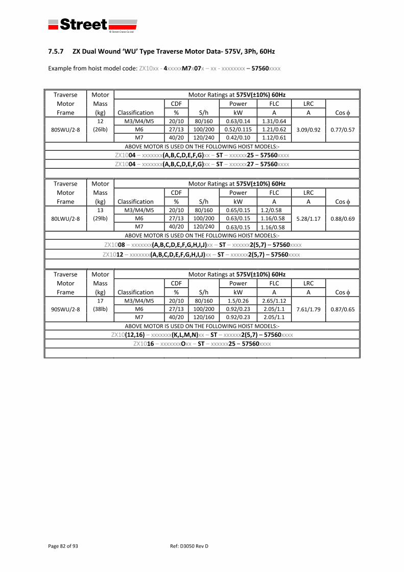
defgh © Street Crane Co Ltd
Page 82 of 93 Ref: D3050 Rev D
7.5.7 ZX Dual Wound ‘WU’ Type Traverse Motor Data‐ 575V, 3Ph, 60Hz Example from hoist model code: ZX10xx ‐ 4xxxxxM7x07x – xx ‐ xxxxxxxx – 57560xxxx
Traverse Motor Motor Ratings at 575V(±10%) 60Hz
Motor Mass
Classification
CDF
S/h
Power FLC LRC
Cos Frame (kg) % kW A A
80SWU/2‐8
12 M3/M4/M5 20/10 80/160 0.63/0.14 1.31/0.64
3.09/0.92 0.77/0.57 (26lb) M6 27/13 100/200 0.52/0.115 1.21/0.62
M7 40/20 120/240 0.42/0.10 1.12/0.61
ABOVE MOTOR IS USED ON THE FOLLOWING HOIST MODELS:‐
ZX1004 – xxxxxxx(A,B,C,D,E,F,G)xx – ST – xxxxxx25 – 57560xxxx ZX1004 – xxxxxxx(A,B,C,D,E,F,G)xx – ST – xxxxxx27 – 57560xxxx
Traverse Motor Motor Ratings at 575V(±10%) 60Hz
Motor Mass
Classification
CDF
S/h
Power FLC LRC
Cos Frame (kg) % kW A A
80LWU/2‐8
13 M3/M4/M5 20/10 80/160 0.65/0.15 1.2/0.58
5.28/1.17 0.88/0.69 (29lb) M6 27/13 100/200 0.63/0.15 1.16/0.58
M7 40/20 120/240 0.63/0.15 1.16/0.58
ABOVE MOTOR IS USED ON THE FOLLOWING HOIST MODELS:‐
ZX1008 – xxxxxxx(A,B,C,D,E,F,G,H,I,J)xx – ST – xxxxxx2(5,7) – 57560xxxx
ZX1012 – xxxxxxx(A,B,C,D,E,F,G,H,I,J)xx – ST – xxxxxx2(5,7) – 57560xxxx
Traverse Motor Motor Ratings at 575V(±10%) 60Hz
Motor Mass
Classification
CDF
S/h
Power FLC LRC
Cos Frame (kg) % kW A A
90SWU/2‐8
17 M3/M4/M5 20/10 80/160 1.5/0.26 2.65/1.12
7.61/1.79 0.87/0.65 (38lb) M6 27/13 100/200 0.92/0.23 2.05/1.1
M7 40/20 120/160 0.92/0.23 2.05/1.1
ABOVE MOTOR IS USED ON THE FOLLOWING HOIST MODELS:‐
ZX10(12,16) – xxxxxxx(K,L,M,N)xx – ST – xxxxxx2(5,7) – 57560xxxx ZX1016 – xxxxxxxOxx – ST – xxxxxx25 – 57560xxxx
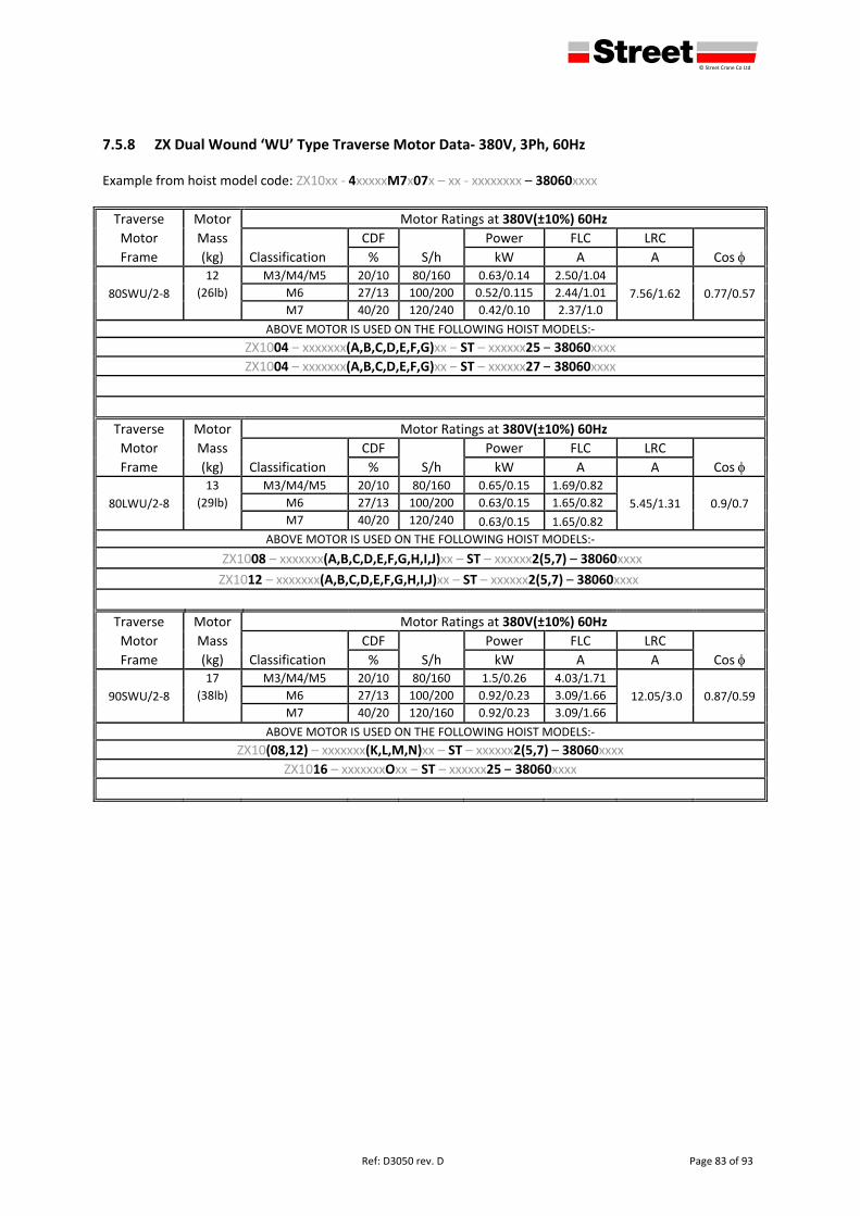
defgh © Street Crane Co Ltd
Ref: D3050 rev. D Page 83 of 93
7.5.8 ZX Dual Wound ‘WU’ Type Traverse Motor Data‐ 380V, 3Ph, 60Hz Example from hoist model code: ZX10xx ‐ 4xxxxxM7x07x – xx ‐ xxxxxxxx – 38060xxxx
Traverse Motor Motor Ratings at 380V(±10%) 60Hz
Motor Mass
Classification
CDF
S/h
Power FLC LRC
Cos Frame (kg) % kW A A
80SWU/2‐8
12 M3/M4/M5 20/10 80/160 0.63/0.14 2.50/1.04
7.56/1.62 0.77/0.57 (26lb) M6 27/13 100/200 0.52/0.115 2.44/1.01
M7 40/20 120/240 0.42/0.10 2.37/1.0
ABOVE MOTOR IS USED ON THE FOLLOWING HOIST MODELS:‐
ZX1004 – xxxxxxx(A,B,C,D,E,F,G)xx – ST – xxxxxx25 – 38060xxxx ZX1004 – xxxxxxx(A,B,C,D,E,F,G)xx – ST – xxxxxx27 – 38060xxxx
Traverse Motor Motor Ratings at 380V(±10%) 60Hz
Motor Mass
Classification
CDF
S/h
Power FLC LRC
Cos Frame (kg) % kW A A
80LWU/2‐8
13 M3/M4/M5 20/10 80/160 0.65/0.15 1.69/0.82
5.45/1.31 0.9/0.7 (29lb) M6 27/13 100/200 0.63/0.15 1.65/0.82
M7 40/20 120/240 0.63/0.15 1.65/0.82
ABOVE MOTOR IS USED ON THE FOLLOWING HOIST MODELS:‐
ZX1008 – xxxxxxx(A,B,C,D,E,F,G,H,I,J)xx – ST – xxxxxx2(5,7) – 38060xxxx
ZX1012 – xxxxxxx(A,B,C,D,E,F,G,H,I,J)xx – ST – xxxxxx2(5,7) – 38060xxxx
Traverse Motor Motor Ratings at 380V(±10%) 60Hz
Motor Mass
Classification
CDF
S/h
Power FLC LRC
Cos Frame (kg) % kW A A
90SWU/2‐8
17 M3/M4/M5 20/10 80/160 1.5/0.26 4.03/1.71
12.05/3.0 0.87/0.59 (38lb) M6 27/13 100/200 0.92/0.23 3.09/1.66
M7 40/20 120/160 0.92/0.23 3.09/1.66
ABOVE MOTOR IS USED ON THE FOLLOWING HOIST MODELS:‐
ZX10(08,12) – xxxxxxx(K,L,M,N)xx – ST – xxxxxx2(5,7) – 38060xxxx ZX1016 – xxxxxxxOxx – ST – xxxxxx25 – 38060xxxx
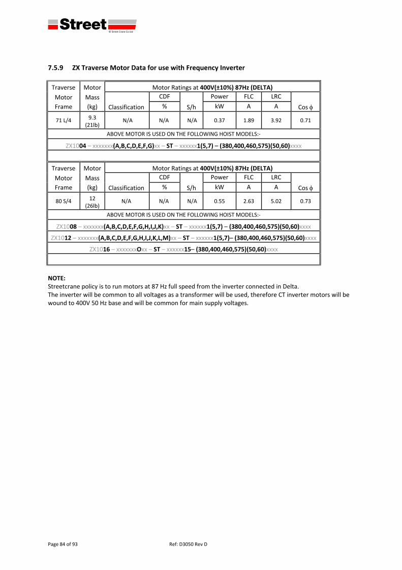
defgh © Street Crane Co Ltd
Page 84 of 93 Ref: D3050 Rev D
7.5.9 ZX Traverse Motor Data for use with Frequency Inverter
Traverse Motor Motor Ratings at 400V(±10%) 87Hz (DELTA)
Motor Mass
Classification
CDF
S/h
Power FLC LRC
Cos Frame (kg) % kW A A
71 L/4 9.3 (21lb)
N/A N/A N/A 0.37 1.89 3.92 0.71
ABOVE MOTOR IS USED ON THE FOLLOWING HOIST MODELS:‐
ZX1004 – xxxxxxx(A,B,C,D,E,F,G)xx – ST – xxxxxx1(5,7) – (380,400,460,575)(50,60)xxxx
Traverse Motor Motor Ratings at 400V(±10%) 87Hz (DELTA)
Motor Mass
Classification
CDF
S/h
Power FLC LRC
Cos Frame (kg) % kW A A
80 S/4 12 (26lb)
N/A N/A N/A 0.55 2.63 5.02 0.73
ABOVE MOTOR IS USED ON THE FOLLOWING HOIST MODELS:‐
ZX1008 – xxxxxxx(A,B,C,D,E,F,G,H,I,J,K)xx – ST – xxxxxx1(5,7) – (380,400,460,575)(50,60)xxxx
ZX1012 – xxxxxxx(A,B,C,D,E,F,G,H,I,J,K,L,M)xx – ST – xxxxxx1(5,7)– (380,400,460,575)(50,60)xxxx
ZX1016 – xxxxxxxOxx – ST – xxxxxx15– (380,400,460,575)(50,60)xxxx
NOTE: Streetcrane policy is to run motors at 87 Hz full speed from the inverter connected in Delta. The inverter will be common to all voltages as a transformer will be used, therefore CT inverter motors will be wound to 400V 50 Hz base and will be common for main supply voltages.
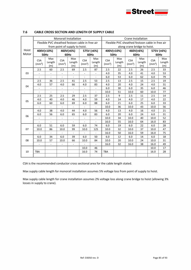
defgh © Street Crane Co Ltd
Ref: D3050 rev. D Page 85 of 93
7.6 CABLE CROSS SECTION AND LENGTH OF SUPPLY CABLE
Hoist Motor
Monorail Installation Crane Installation
Flexible PVC sheathed festoon cable in free air from point of supply to hoist.
Flexible PVC sheathed festoon cable in free air along crane bridge to hoist.
400V(±10%) 50Hz
460V(±6%) 60Hz
575V (±6%) 60Hz
400V(±10%) 50Hz
460V(±6%) 60Hz
575V (±6%) 60Hz
CSA (mm²)
Max Length (m)
CSA (mm²)
Max Length (m)
CSA (mm²)
Max Length(m)
CSA (mm²)
Max Length (m)
CSA (mm²)
Max Length (m)
CSA (mm²)
Max Length(m)
03
2.5 60 2.5 69 2.5 87 2.5 22 2.5 26 2.5 33
‐ ‐ ‐ ‐ ‐ ‐ 4.0 35 4.0 41 4.0 53
‐ ‐ ‐ ‐ ‐ ‐ 6.0 53 6.0 62 6.0 79
04
2.5 36 2.5 41 2.5 53 2.5 13 2.5 15 2.5 19
4.0 57 4.0 66 4.0 83 4.0 20 4.0 24 4.0 31
‐ ‐ ‐ ‐ ‐ ‐ 6.0 30 6.0 35 6.0 46
‐ ‐ ‐ ‐ ‐ ‐ 10.0 51 10.0 60 10.0 77
05
2.5 25 2.5 29 2.5 37 2.5 9 2.5 11 2.5 14
4.0 40 4.0 46 4.0 59 4.0 14 4.0 17 4.0 22
6.0 60 6.0 69 6.0 88 6.0 21 6.0 25 6.0 33
‐ ‐ ‐ ‐ ‐ ‐ 10.0 36 10.0 43 10.0 56
06
4.0 38 4.0 44 4.0 56 4.0 13 4.0 16 4.0 21
6.0 56 6.0 65 6.0 83 6.0 20 6.0 24 6.0 31
‐ ‐ ‐ ‐ ‐ ‐ 10.0 34 10.0 40 10.0 52
‐ ‐ ‐ ‐ ‐ ‐ 16.0 55 16.0 64 16.0 83
07
6.0 51 6.0 59 6.0 74 6.0 19 6.0 22 6.0 28
10.0 86 10.0 99 10.0 125 10.0 32 10.0 37 10.0 47
‐ ‐ ‐ ‐ ‐ ‐ 16.0 50 16.0 59 16.0 75
08
6.0 34 6.0 39 6.0 50 6.0 12 6.0 14 6.0 18
10.0 57 10.0 66 10.0 84 10.0 20 10.0 24 10.0 31
‐ ‐ ‐ ‐ ‐ ‐ 16.0 32 16.0 38 16.0 49
10
10.0 46 10.0 17
TBA 16.0 74 TBA 16.0 28
CSA is the recommended conductor cross sectional area for the cable length stated. Max supply cable length for monorail installation assumes 5% voltage loss from point of supply to hoist. Max supply cable length for crane installation assumes 2% voltage loss along crane bridge to hoist (allowing 3% losses in supply to crane).

defgh © Street Crane Co Ltd
Page 86 of 93 Ref: D3050 Rev D
7.7 RESULTS OF PERIODIC TESTS
HOIST SERIAL No Page No
Date Defects found Remedial actions
Estimated remaining
service life (see7.2)
Signature

defgh © Street Crane Co Ltd
Ref: D3050 rev. D Page 87 of 93
7.8 RECORD OF REPLACEMENT PARTS (ropes, brakes, sheaves etc.)
HOIST SERIAL No Page No
Date Hours In Service
Part description / Reason for replacement Signature

defgh © Street Crane Co Ltd
Page 88 of 93 Ref: D3050 Rev D
HOIST SERIAL No Page No
Date Hours In Service
Part description / Reason for replacement Signature

defgh © Street Crane Co Ltd
Ref: D3050 rev. D Page 89 of 93
NOTES:

defgh © Street Crane Co Ltd
Page 90 of 93 Ref: D3050 Rev D
NOTES:

defgh © Street Crane Co Ltd
Ref: D3050 rev. D Page 91 of 93
NOTES:

defgh © Street Crane Co Ltd
Page 92 of 93 Ref: D3050 Rev D
NOTES:
www.streetcrane.co.uk
56565656def 565656565656565656565656565565656565656565656565656565656565656565656565656
Street Crane Company Limited, Chapel‐en‐le‐Frith, High Peak SK23 0PH, UK Email: [email protected] Web: www.streetcrane.co.uk Telephone: +44 (0) 1298 812456 Fax: +44 (0) 1298 814945
Certificate No. FM13635 Quality Management ISO 9001