Embed Size (px)
Citation preview
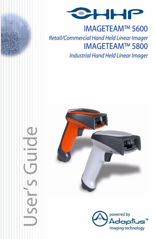
™
IMAGETEAM™ 5600Retail/Commercial Hand Held Linear Imager
IMAGETEAM™ 5800Industrial Hand Held Linear Imager
Use
r’s G
uid
e
Disclaimer
Hand Held Products, Inc. d/b/a HHP (“HHP”) reserves the right to make changes in specifications and other information contained in this document without prior notice, and the reader should in all cases consult HHP to determine whether any such changes have been made. The information in this publication does not represent a commitment on the part of HHP.HHP shall not be liable for technical or editorial errors or omissions contained herein; nor for incidental or consequential damages resulting from the furnishing, performance, or use of this material.This document contains proprietary information which is protected by copyright. All rights are reserved. No part of this document may be photocopied, reproduced, or translated into another language without the prior written consent of HHP. 2002-2003 Hand Held Products, Inc. All rights reserved.Web Address: www.HHP.com
Table of Contents
Chapter 1 - Getting Started
IMAGETEAM 5600............................................................. 1-1About This Manual ............................................................... 1-1Unpacking the Scanner ......................................................... 1-1IT5600 Models...................................................................... 1-2IT5800 Models...................................................................... 1-2IT5600/5800 Scanner Identification ..................................... 1-3IT5800 Scanner (with aimer beam option) Identification .... 1-4Connecting the Scanner When Powered by Host
(Keyboard Wedge) ............................................................. 1-5Reading Techniques.............................................................. 1-6Resetting the Standard Product Defaults .............................. 1-6Plug and Play ........................................................................ 1-6Keyboard Wedge Connection............................................... 1-7
Laptop Direct Connect ................................................... 1-7RS-232............................................................................ 1-7Wand Emulation Plug & Play ........................................ 1-8IBM 4683 Ports 5B, 9B, and 17 Interface...................... 1-8
Connecting the Scanner with USB ..................................... 1-10IBM SurePos ................................................................ 1-10USB PC or Macintosh Keyboard ................................. 1-11USB HID...................................................................... 1-11USB Com Port Emulation............................................ 1-12
Connecting the Scanner with Serial Wedge ....................... 1-12
Chapter 2 - Terminal Interfaces
Terminal ID .......................................................................... 2-1Supported Terminals............................................................. 2-2Keyboard Country ................................................................ 2-4Keyboard Style ..................................................................... 2-5Keyboard Modifiers.............................................................. 2-6
i
Connecting the Scanner with RS-232 Serial Port ................. 2-8RS-232 Baud Rate .......................................................... 2-9RS-232 Word Length: Data Bits, Stop Bits, and Parity2-10RS-232 Handshaking.................................................... 2-11Wand Emulation Connection........................................ 2-11Wand Emulation Transmission Rate ............................ 2-12Wand Emulation Polarity ............................................. 2-12Wand Emulation Idle.................................................... 2-13
Wand Emulation.................................................................. 2-13Data Block Size ............................................................ 2-13Delay Between Blocks.................................................. 2-14Overall Checksum ........................................................ 2-14
Chapter 3 - Output
Good Read Indicators............................................................ 3-1Beeper – Good Read....................................................... 3-1Beeper Volume – Good Read......................................... 3-1Beeper Pitch – Good Read.............................................. 3-1Beeper Duration – Good Read........................................ 3-2LED – Good Read .......................................................... 3-2Number of Beeps – Good Read...................................... 3-2
Good Read Delay .................................................................. 3-3User-Specified Good Read Delay................................... 3-3
Trigger Modes....................................................................... 3-3Manual/Serial Trigger..................................................... 3-3Automatic Trigger .......................................................... 3-4Presentation Mode .......................................................... 3-5
Hands Free Time-Out............................................................ 3-5Reread Delay......................................................................... 3-5
User-Specified Reread Delay ......................................... 3-6Aimer Beam Delay (Aimer Beam option only) .................... 3-7
User-Specified Aimer Beam Delay ................................ 3-7Aimer Mode (Aimer Beam option only)............................... 3-7Aimer Beam Time-Out (Aimer Beam option only).............. 3-8Centering Window ................................................................ 3-8
ii
Output Sequence Overview.................................................3-10Output Sequence Editor ................................................3-11Require Output Sequence .............................................3-11
Multiple Symbols ................................................................3-13No Read...............................................................................3-13Video Reverse .....................................................................3-13
Chapter 4 - Data Editing
Prefix/Suffix Overview .........................................................4-1To Clear One or All Prefixes or Suffixes: ......................4-3To Add a Carriage Return Suffix to all Symbologies.....4-3Prefix Selections .............................................................4-3Suffix Selections .............................................................4-4Function Code Transmit .................................................4-4
Intercharacter, Interfunction, and Intermessage Delays ........4-4Intercharacter Delay........................................................4-5User Specified Intercharacter Delay ...............................4-5Interfunction Delay .........................................................4-6Intermessage Delay.........................................................4-6
Chapter 5 - Data Formatting
Data Format Editor Introduction ...........................................5-1To Add a Data Format ....................................................5-1Other Programming Selections.......................................5-2Data Format Editor Commands ......................................5-2Data Format Editor .........................................................5-4Data Formatter ................................................................5-5Alternate Data Formats ...................................................5-5
Chapter 6 - Secondary Interface
IT5600 Models ......................................................................6-1IT5800 Models ......................................................................6-1Enabling Secondary Interface ...............................................6-2Secondary RS-232 Connection .............................................6-2Secondary Code 39 Wand Emulation ...................................6-2
iii
Secondary Laser Emulation .................................................. 6-3Laser Emulation Transmission Rate ..................................... 6-3Laser Emulation Polarity....................................................... 6-4Laser Emulation Idle ............................................................. 6-4Secondary Trigger Mode....................................................... 6-4Hands Free Time-Out............................................................ 6-5
Chapter 7 - Symbologies
Introduction ........................................................................... 7-1All Symbologies.................................................................... 7-1Message Length .................................................................... 7-2Codabar ................................................................................. 7-3
Codabar Start/Stop Characters....................................... 7-3Codabar Check Character............................................... 7-3Codabar Concatenation................................................... 7-4Codabar Message Length ............................................... 7-5
Code 39 ................................................................................. 7-5Code 39 Start/Stop Characters ....................................... 7-5Code 39 Check Character ............................................... 7-6Code 39 Message Length ............................................... 7-6Code 39 Append ............................................................. 7-7Code 32 Pharmaceutical (PARAF)................................. 7-7Full ASCII ...................................................................... 7-8Code 39 Code Page......................................................... 7-9
Interleaved 2 of 5 .................................................................. 7-9Check Digit..................................................................... 7-9Interleaved 2 of 5 Message Length............................... 7-10
Code 93 ............................................................................... 7-11Code 93 Message Length ............................................. 7-11Code 93 Code Page....................................................... 7-11
Code 2 of 5 .......................................................................... 7-12Code 2 of 5 Message Length ........................................ 7-12IATA Code 2 of 5 Message Length.............................. 7-13
Matrix 2 of 5........................................................................ 7-13Matrix 2 of 5 Message Length...................................... 7-14
iv
Code 11................................................................................7-14Check Digits Required..................................................7-14Code 11 Message Length..............................................7-15
Code 128..............................................................................7-15ISBT 128 Concatenation...............................................7-16Code 128 Message Length............................................7-16Code 128 Code Page.....................................................7-16
Telepen ................................................................................7-17Telepen Output .............................................................7-17Telepen Message Length ..............................................7-17
UPC A .................................................................................7-18UPC A Check Digit ......................................................7-18UPC A Number System................................................7-18UPC A Addenda ...........................................................7-19UPC A Addenda Required............................................7-19UPC A Addenda Separator ...........................................7-19
UPC-A/EAN-13 with Extended Coupon Code ...................7-20UPC E0 and UPC E1...........................................................7-20
UPC E0 and UPC E1 Expand .......................................7-21UPC E0 and UPC E1 Addenda Required .....................7-21UPC E0 and UPC E1 Addenda Separator ....................7-21UPC E0 Check Digit.....................................................7-22UPC E0 Number System ..............................................7-22UPC E0 Addenda..........................................................7-22
EAN/JAN 13 .......................................................................7-23EAN/JAN 13 Check Digit ............................................7-23EAN/JAN 13 Addenda .................................................7-23EAN/JAN 13 Addenda Required..................................7-24EAN/JAN 13 Addenda Separator .................................7-24ISBN Translate .............................................................7-24
EAN/JAN 8 .........................................................................7-25EAN/JAN 8 Check Digit ..............................................7-25EAN/JAN 8 Addenda ...................................................7-25EAN/JAN 8 Addenda Required....................................7-26EAN/JAN 8 Addenda Separator ...................................7-26
v
MSI...................................................................................... 7-26MSI Check Character ................................................... 7-27MSI Message Length.................................................... 7-27
Plessey Code ....................................................................... 7-28Plessey Message Length............................................... 7-28
RSS Limited ........................................................................ 7-29RSS Expanded..................................................................... 7-30
RSS Expanded Message Length................................... 7-30EAN•UCC Emulation ......................................................... 7-30China Post Code.................................................................. 7-31Korea Post Code.................................................................. 7-32
Korea Post Message Length ......................................... 7-32PosiCode A and B ............................................................... 7-33
PosiCode Message Length............................................ 7-33Codablock F ........................................................................ 7-34
Codablock F Message Length ...................................... 7-34Code 16K ............................................................................ 7-35
Code 16K Message Length........................................... 7-35Code 49 ............................................................................... 7-36
Code 49 Message Length ............................................. 7-36
Chapter 8 - Interface Keys
Keyboard Function Relationships ......................................... 8-1Supported Interface Keys...................................................... 8-3
Chapter 9 - Utilities
To Add a Test Code I.D. Prefix to All Symbologies ............ 9-1Show Software Revision ....................................................... 9-1Show Data Format................................................................. 9-1Resetting the Standard Product Defaults............................... 9-1Temporary Visual Menu 2003 Configuration....................... 9-2
Chapter 10 - Visual Menu 2003
Visual Menu 2003 Introduction .......................................... 10-1Installing Visual Menu 2003 from the Web ................. 10-1
vi
Chapter 11 - Serial Programming Commands
Conventions.........................................................................11-1Menu Command Syntax......................................................11-1
Query Commands .........................................................11-2Concatenation of Multiple Commands .........................11-2Responses......................................................................11-2Examples of Query Commands ....................................11-3
Trigger Commands..............................................................11-4Resetting the Standard Product Defaults.............................11-4Menu Commands ................................................................11-5
Chapter 12 - Product Specifications
IMAGETEAM 5600 Product Specifications ......................12-1IMAGETEAM 5600 Depth of Field ...................................12-2IMAGETEAM 5800 Product Specifications ......................12-3IMAGETEAM 5800 Depth of Field ...................................12-4Standard Cable Pinouts .......................................................12-5
Chapter 13 - Maintenance
Repairs.................................................................................13-1Maintenance ........................................................................13-1
Cleaning the Scanner’s Window...................................13-1Inspecting Cords and Connectors .................................13-1Replacing the Interface Cable.......................................13-2
Troubleshooting...................................................................13-3
Chapter 14 - Customer Support
Obtaining Factory Service...................................................14-1Help Desk ............................................................................14-2
Limited Warranty..........................................................14-3
Appendix A
Symbology Chart..................................................................A-1ASCII Conversion Chart (Code Page 1252) ........................A-2
vii

Code Page Mapping of Printed Bar Codes .......................... A-4
Sample Symbols
viii
Statement of Agency Compliance
This device complies with part 15 of the FCC Rules. Operation is subject to the following two conditions: (1) this device may not cause harmful interference, and (2) this device must accept any interference received, including interference that may cause undesired operation.
FCC Class B Compliance Statement
This equipment has been tested and found to comply with the limits for a Class B digital device pursuant to part 15 of the FCC Rules. These limits are designed to provide reasonable protection against harmful interference in a residential installation. This equipment generates, uses, and can radiate radio frequency energy and, if not installed and used in accordance with the instructions, may cause harmful interference to radio communications. However, there is no guarantee that interference will not occur in a particular installation. If this equipment does cause harmful interference to radio or television reception, which can be determined by turning the equipment off and on, the user is encouraged to try to correct the interference by one or more of the following measures:
• Reorient or relocate the receiving antenna.• Increase the separation between the equipment and receiver.• Connect the equipment into an outlet on a circuit different from that to
which the receiver is connected.• Consult the dealer or an experienced radio or television technician for
help.Caution: Any changes or modifications made to this device that are not expressly approved by Hand Held Products, Inc. may void the user’s authority to operate the equipment.
Note: To maintain compliance with FCC Rules and Regulations, cables connected to this device must be shielded cables, in which the cable shield wire(s) have been grounded (tied) to the connector shell.
Canadian Notice
This equipment does not exceed the Class B limits for radio noise emissions as described in the Radio Interference Regulations of the Canadian Department of Communications.
Le present appareil numerique n’emet pas de bruits radioelectriques depassant les limites applicables aux appareils numeriques de la classe B prescrites dans le Reglement sur le brouillage radioelectrique edicte par le ministere des Communications du Canada.
The CE mark on the product indicates that the system has been tested to and conforms with the provisions noted within the 89/336/EEC Electromagnetic Compatibility Directive and the 73/23/EEC Low Voltage Directive.
For CE-related inquiries, please contact:Hand Held Products, Inc.Nijverheidsweg 95627 BT EindhovenThe Netherlands
HHP shall not be liable for use of our product with equipment (i.e., power supplies, personal computers, etc.) that is not CE marked and does not comply with the Low Voltage Directive.
UL and cUL Statement
UL listed UL1950 and CSA 22.2 No.950. cUL listed UL1950 and CSA 22.2 No 950.
LED Safety Statement
This device has been tested in accordance with EN60825-1 LED safety, and has been certified to be under the limits of a Class 1 LED device.
Aimer Beam Safety Statement (IT5800 Option only)
This device has been tested in accordance with and complies with EN60825-1: 1994+A11+A2 and 21 CFR 1040.10 and 1040.11, except for deviations pursuant to Laser Notice No. 50, dated July 26, 2001.
LASER LIGHT, DO NOT STARE INTO BEAM, CLASS 2 LASER PRODUCT, 1.0 mW MAX OUTPUT: 650nM.
Caution: Use of controls or adjustments or performance of procedures other than those specified herein may result in hazardous radiation exposure.
TÜV Statement
TÜV or GS marked to EN60950 and EN60825-1.
C-Tick Statement
Conforms to AS/NZS 3548. C-Tick number: N10410.

Mexico
Patents
Please refer to the IT5600/5800 packaging for patent information.
Solids and Water Protection
The IT5600 has a rating of IP41, immunity of foreign particles and dripping water.
The IT5800 has a rating of IP54, immunity of windblown dust penetration and splashing water.
Certified

1G
IT560
etting Started
IMAGETEAM 5600
The IMAGETEAM™ 5600 and 5800 mark a new performance level for hand held scanners. Both the IT5600 and IT5800 are powered by HHP’s AdaptusTM Imaging Technology. The performance of Adaptus technology delivers aggressive read rates and depths of field on 1D, stacked linear, and matrix codes.
Designed for today’s demanding retail and commercial environments, the IT5600 offers a superior reading range, durability, and the ability to read poor quality bar codes. Linear imaging technology is defined by a bright and sharply focused aiming line, high resolution imaging, and fast reading speed. The IT5600 is comfortable to hold, easy to use, rugged, and excellent for retail applications, as well as for all general scanning applications.
The IT5800 hand held industrial image reader is the first industrial class reader to be powered by HHP’s Adaptus imaging technology. Adaptus technology allows you to read bar codes at ranges up to 82 inches on paper labels. In addition, this technology allows your IT5800 to pick up and process your bar code image 270 times per second. Although the IT5800 uses the same general ergonomic design as the IT5600, the IT5800 is built to withstand your toughest industrial applications.
About This Manual
This User’s Guide provides installation and programming instructions for the IMAGETEAM 5600/5800. Product specifications, dimensions, warranty, and customer support information are also included.
HHP’s bar code scanners are factory programmed for the most common terminal and communications settings. If you need to change these settings, programming is accomplished by scanning the bar codes in this guide.
An asterisk (*) next to an option indicates the default setting.
Unpacking the Scanner
After you open the shipping carton containing the IT5600/5800, take the following steps:
• Check to make sure everything you ordered is present.• Save the shipping container for later storage or shipping.• Check for damage during shipment. Report damage immediately to the
carrier who delivered the carton.
0/5800 User’s Guide 1 - 1
IT5600 Models
Note: HHP’s IT5600 scanner may be used with many interfaces, which are described in this user’s guide. Refer to the chart below to determine the models that can be used with the interface you are using. Refer to Chapter 6 for programming information regarding Secondary Interfaces.
The chart below lists the IT5600 scanner models. “SR” indicates “Standard Range” linear optics.
IT5800 Models
Note: HHP’s IT5800 scanner may be used with many interfaces, which are described in this user’s guide. Refer to the chart below to determine the models that can be used with the interface you are using. Refer to Chapter 6 for programming information regarding Secondary Interfaces.
The chart below lists the IT5800 scanner models. “SR” indicates “Standard Range” linear optics. If the product number has the number one (1) as the last character, the unit contains the aimer beam option (e.g., 5800SR001).
Models Primary InterfacesSecondary Interfaces
5600SR000 TTL Level 232 Laser Emulation
5600SR010 Keyboard Wedge, TTL level 232, TTL level 232 serial wedge, IBM 4683, wand emula-tion
Wand Emulation, TTL level 232
5600SR030 True RS-232, True RS-232 serial wedge
True RS-232
5600SR050 Keyboard wedge, TTL level 232, TTL level 232 serial wedge, IBM 4683, wand emula-tion, USB keyboard, USB HID, USB retail (IBM SurePOS)
Wand Emulation, TTL level 232
Models Primary InterfacesSecondary Interfaces
5800SR00X TTL Level 232 Laser Emulation
5800SR03X True RS-232, True RS-232 serial wedge
True RS-232
1 - 2 IT5600/5800 User’s Guide
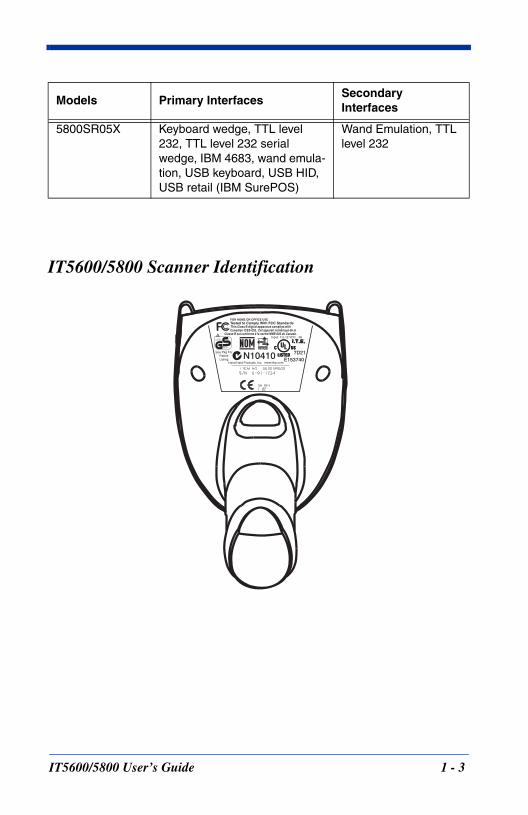
IT5600/5800 Scanner Identification
5800SR05X Keyboard wedge, TTL level 232, TTL level 232 serial wedge, IBM 4683, wand emula-tion, USB keyboard, USB HID, USB retail (IBM SurePOS)
Wand Emulation, TTL level 232
Models Primary InterfacesSecondary Interfaces
IT5600/5800 User’s Guide 1 - 3
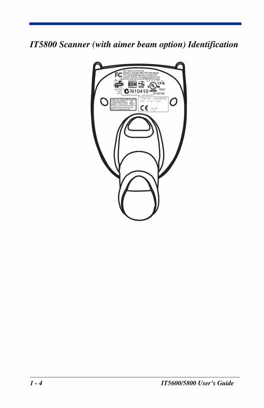
IT5800 Scanner (with aimer beam option) Identification
1 - 4 IT5600/5800 User’s Guide
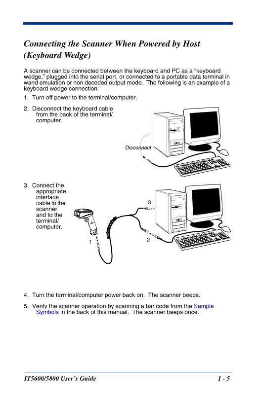
Connecting the Scanner When Powered by Host (Keyboard Wedge)
A scanner can be connected between the keyboard and PC as a “keyboard wedge,” plugged into the serial port, or connected to a portable data terminal in wand emulation or non decoded output mode. The following is an example of a keyboard wedge connection:
1. Turn off power to the terminal/computer.
2. Disconnect the keyboard cable from the back of the terminal/computer.
3. Connect the appropriate interface cable to the scanner and to the terminal/computer.
4. Turn the terminal/computer power back on. The scanner beeps.
5. Verify the scanner operation by scanning a bar code from the Sample Symbols in the back of this manual. The scanner beeps once.
Disconnect
1 2
3
IT5600/5800 User’s Guide 1 - 5
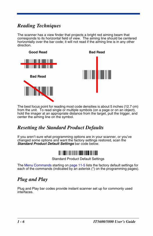
Reading Techniques
The scanner has a view finder that projects a bright red aiming beam that corresponds to its horizontal field of view. The aiming line should be centered horizontally over the bar code; it will not read if the aiming line is in any other direction.
The best focus point for reading most code densities is about 5 inches (12.7 cm) from the unit. To read single or multiple symbols (on a page or on an object), hold the imager at an appropriate distance from the target, pull the trigger, and center the aiming line on the symbol.
Resetting the Standard Product Defaults
If you aren’t sure what programming options are in your scanner, or you’ve changed some options and want the factory settings restored, scan the Standard Product Default Settings bar code below.
The Menu Commands starting on page 11-5 lists the factory default settings for each of the commands (indicated by an asterisk (*) on the programming pages).
Plug and Play
Plug and Play bar codes provide instant scanner set up for commonly used interfaces.
Good Read
Bad Read
Bad Read
Standard Product Default Settings
1 - 6 IT5600/5800 User’s Guide
Note: After you scan one of the codes, power cycle the host terminal to have the interface in effect.
Keyboard Wedge Connection
IMAGETEAM 5600 scanners are factory programmed for a keyboard wedge interface to an IBM PC AT with a USA keyboard. If this is your interface and you do not need to modify the settings, skip to Chapter 3 - Output.
If you programmed the scanner for a different terminal interface and you want to change to an IBM PC AT and compatibles keyboard wedge interface, scan the bar code below.
Note: The following bar code also programs a carriage return (CR) suffix.
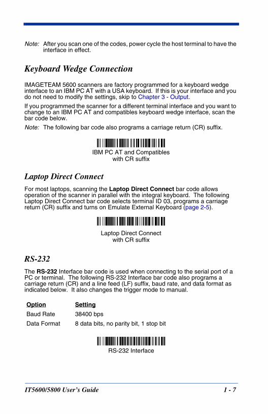
Laptop Direct ConnectFor most laptops, scanning the Laptop Direct Connect bar code allows operation of the scanner in parallel with the integral keyboard. The following Laptop Direct Connect bar code selects terminal ID 03, programs a carriage return (CR) suffix and turns on Emulate External Keyboard (page 2-5).
RS-232The RS-232 Interface bar code is used when connecting to the serial port of a PC or terminal. The following RS-232 Interface bar code also programs a carriage return (CR) and a line feed (LF) suffix, baud rate, and data format as indicated below. It also changes the trigger mode to manual.
Option Setting
Baud Rate 38400 bps
Data Format 8 data bits, no parity bit, 1 stop bit
IBM PC AT and Compatibles with CR suffix
Laptop Direct Connectwith CR suffix
RS-232 Interface
IT5600/5800 User’s Guide 1 - 7
Wand Emulation Plug & PlayIn Wand Emulation mode, the imager decodes the bar code then sends data in the same format as a wand imager. The Code 39 Format converts all symbologies to Code 39.
The Same Code Format transmits UPC, EAN, Code 128 and Interleaved 2 of 5 without any changes, but converts all other symbologies to Code 39.
The Wand Emulation Plug & Play Code 39 Format bar code below sets the terminal ID to 61. The Wand Emulation Plug & Play Same Code Format bar code sets the terminal ID to 64. These Plug & Play bar codes also set the Transmission Rate to 25 inches per second, Output Polarity to black high, and Idle State to high. (If you want to change the terminal ID only, without changing any other imager settings, please refer to Wand Emulation Connection on page 2-11.)
IBM 4683 Ports 5B, 9B, and 17 InterfaceScan one of the following “Plug and Play” codes to program the 56/5800SR050 for IBM 4683 Port 5B, 9B, or 17.
Note: After scanning one of these codes, you must power cycle the cash register.
Wand Emulation Same Code
Wand Emulation (Code 39 Format)
IBM 4683 Port 5B Interface
IBM 4683 Port 9B HHBCR-1 Interface
IBM 4683 Port 17 Interface
IBM 4683 Port 9B HHBCR-2 Interface
1 - 8 IT5600/5800 User’s Guide
Each bar code above also programs the following suffixes for each symbology:
* Suffixes programmed for Code 128 with IBM 4683 Port 5B, IBM 4683 Port 9B HHBCR-1,and IBM 4683 Port 17 Interfaces**Suffixes programmed for Code 128 with IBM 4683 Port 9 HHBCR-2 Interface
Symbology SuffixEAN 8 0CEAN 13 16UPC A 0DUPC E 0ACode 39 00 0A 0BInterleaved 2 of 5 00 0D 0BCode 128 * 00 0A 0BCode 128 ** 00 18 0B
IT5600/5800 User’s Guide 1 - 9
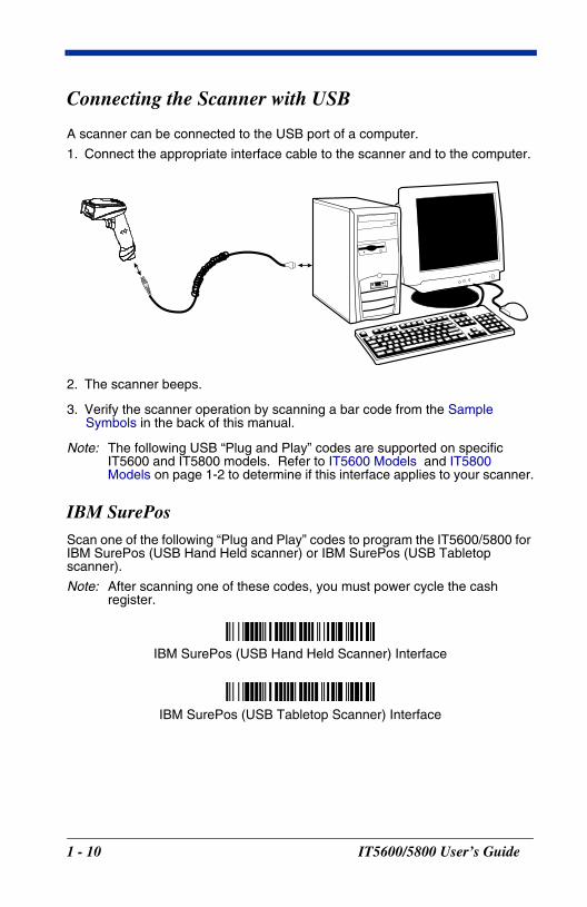
Connecting the Scanner with USB
A scanner can be connected to the USB port of a computer.
1. Connect the appropriate interface cable to the scanner and to the computer.
2. The scanner beeps.
3. Verify the scanner operation by scanning a bar code from the Sample Symbols in the back of this manual.
Note: The following USB “Plug and Play” codes are supported on specific IT5600 and IT5800 models. Refer to IT5600 Models and IT5800 Models on page 1-2 to determine if this interface applies to your scanner.
IBM SurePosScan one of the following “Plug and Play” codes to program the IT5600/5800 for IBM SurePos (USB Hand Held scanner) or IBM SurePos (USB Tabletop scanner).
Note: After scanning one of these codes, you must power cycle the cash register.
IBM SurePos (USB Hand Held Scanner) Interface
IBM SurePos (USB Tabletop Scanner) Interface
1 - 10 IT5600/5800 User’s Guide
Each bar code above also programs the following suffixes for each symbology:
USB PC or Macintosh KeyboardScan one of the following codes to program the IT5600/5800 for USB PC Keyboard or USB Macintosh Keyboard. Scanning these codes adds a CR and LF, along with selecting the terminal ID (USB PC Keyboard - 124, USB Macintosh Keyboard - 125).
USB HIDScan the following code to program the IT5600/5800 for USB HID bar code scanners. Scanning this code changes the terminal ID to 131.
Symbology SuffixEAN 8 0CEAN 13 16UPC A 0DUPC E 0ACode 39 00 0A 0BInterleaved 2 of 5 00 0D 0BCode 128 00 18 0B
USB Keyboard (PC)
USB Keyboard (Mac)
USB HID Bar Code Scanner
IT5600/5800 User’s Guide 1 - 11
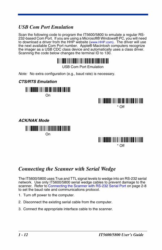
USB Com Port EmulationScan the following code to program the IT5600/5800 to emulate a regular RS-232-based Com Port. If you are using a Microsoft® Windows® PC, you will need to download a driver from the HHP website (www.HHP.com). The driver will use the next available Com Port number. Apple® Macintosh computers recognize the imager as a USB CDC class device and automatically uses a class driver. Scanning the code below changes the terminal ID to 130.
Note: No extra configuration (e.g., baud rate) is necessary.
CTS/RTS Emulation
ACK/NAK Mode
Connecting the Scanner with Serial Wedge
The IT5600/5800 uses True and TTL signal levels to wedge into an RS-232 serial network. Use only IT5600/5800 serial wedge cables to prevent damage to the scanner. Refer to Connecting the Scanner with RS-232 Serial Port on page 2-8 to set the baud rate and communications protocol.
1. Turn off power to the computer.
2. Disconnect the existing serial cable from the computer.
3. Connect the appropriate interface cable to the scanner.
USB Com Port Emulation
On
* Off
On
* Off
1 - 12 IT5600/5800 User’s Guide
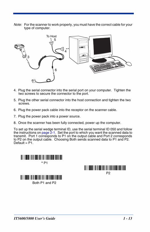
Note: For the scanner to work properly, you must have the correct cable for your type of computer.
4. Plug the serial connector into the serial port on your computer. Tighten the two screws to secure the connector to the port.
5. Plug the other serial connector into the host connection and tighten the two screws.
6. Plug the power pack cable into the receptor on the scanner cable.
7. Plug the power pack into a power source.
8. Once the scanner has been fully connected, power up the computer.
To set up the serial wedge terminal ID, use the serial terminal ID 050 and follow the instructions on page 2-1. Set the port to which you want the scanned data to transmit. Port 1 corresponds to P1 on the output cable and Port 2 corresponds to P2 on the output cable. Choosing Both sends scanned data to P1 and P2. Default = P1.
3
4
5To Host
6
* P1
P2
Both P1 and P2
IT5600/5800 User’s Guide 1 - 13

1 - 14 IT5600/5800 User’s Guide
2T
IT560
erminal Interfaces
Terminal ID
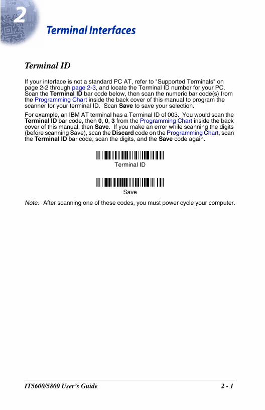
If your interface is not a standard PC AT, refer to "Supported Terminals" on page 2-2 through page 2-3, and locate the Terminal ID number for your PC. Scan the Terminal ID bar code below, then scan the numeric bar code(s) from the Programming Chart inside the back cover of this manual to program the scanner for your terminal ID. Scan Save to save your selection.
For example, an IBM AT terminal has a Terminal ID of 003. You would scan the Terminal ID bar code, then 0, 0, 3 from the Programming Chart inside the back cover of this manual, then Save. If you make an error while scanning the digits (before scanning Save), scan the Discard code on the Programming Chart, scan the Terminal ID bar code, scan the digits, and the Save code again.
Note: After scanning one of these codes, you must power cycle your computer.
Terminal ID
Save
0/5800 User’s Guide 2 - 1
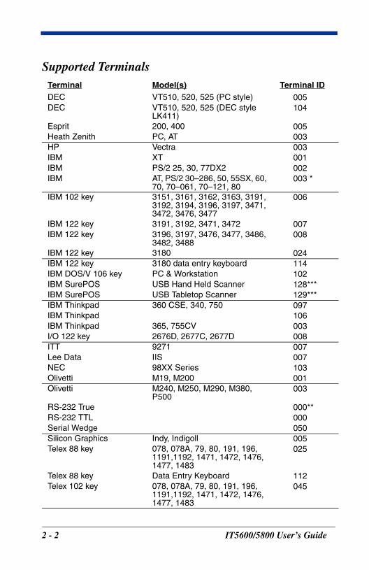
Supported Terminals Terminal Model(s) Terminal IDDEC VT510, 520, 525 (PC style) 005DEC VT510, 520, 525 (DEC style
LK411)104
Esprit 200, 400 005Heath Zenith PC, AT 003HP Vectra 003IBM XT 001IBM PS/2 25, 30, 77DX2 002IBM AT, PS/2 30–286, 50, 55SX, 60,
70, 70–061, 70–121, 80003 *
IBM 102 key 3151, 3161, 3162, 3163, 3191, 3192, 3194, 3196, 3197, 3471, 3472, 3476, 3477
006
IBM 122 key 3191, 3192, 3471, 3472 007IBM 122 key 3196, 3197, 3476, 3477, 3486,
3482, 3488008
IBM 122 key 3180 024IBM 122 key 3180 data entry keyboard 114IBM DOS/V 106 key PC & Workstation 102IBM SurePOS USB Hand Held Scanner 128***IBM SurePOS USB Tabletop Scanner 129***IBM Thinkpad 360 CSE, 340, 750 097IBM Thinkpad 106IBM Thinkpad 365, 755CV 003I/O 122 key 2676D, 2677C, 2677D 008ITT 9271 007Lee Data IIS 007NEC 98XX Series 103Olivetti M19, M200 001Olivetti M240, M250, M290, M380,
P500003
RS-232 True 000**RS-232 TTL 000Serial Wedge 050Silicon Graphics Indy, Indigoll 005Telex 88 key 078, 078A, 79, 80, 191, 196,
1191,1192, 1471, 1472, 1476, 1477, 1483
025
Telex 88 key Data Entry Keyboard 112Telex 102 key 078, 078A, 79, 80, 191, 196,
1191,1192, 1471, 1472, 1476, 1477, 1483
045
2 - 2 IT5600/5800 User’s Guide
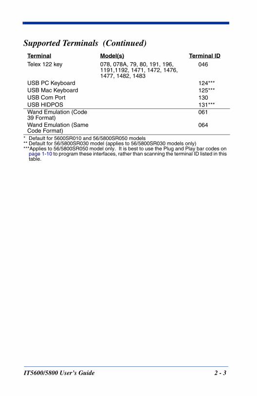
* Default for 5600SR010 and 56/5800SR050 models** Default for 56/5800SR030 model (applies to 56/5800SR030 models only)***Applies to 56/5800SR050 model only. It is best to use the Plug and Play bar codes on
page 1-10 to program these interfaces, rather than scanning the terminal ID listed in this table.
Telex 122 key 078, 078A, 79, 80, 191, 196,1191,1192, 1471, 1472, 1476, 1477, 1482, 1483
046
USB PC Keyboard 124***USB Mac Keyboard 125***USB Com Port 130USB HIDPOS 131***Wand Emulation (Code 39 Format)
061
Wand Emulation (Same Code Format)
064
Supported Terminals (Continued)Terminal Model(s) Terminal ID
IT5600/5800 User’s Guide 2 - 3
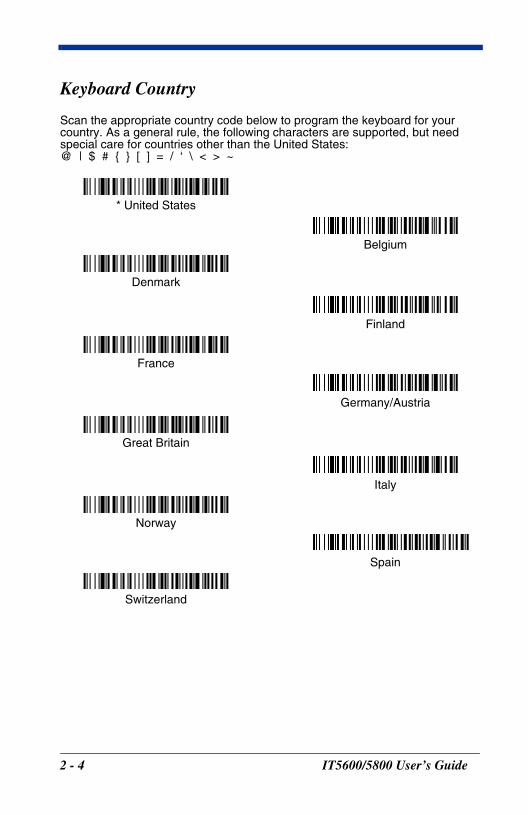
Keyboard Country
Scan the appropriate country code below to program the keyboard for your country. As a general rule, the following characters are supported, but need special care for countries other than the United States:@ | $ # { } [ ] = / ‘ \ < > ~
* United States
Denmark
France
Germany/Austria
Great Britain
Italy
Norway
Spain
Switzerland
Belgium
Finland
2 - 4 IT5600/5800 User’s Guide
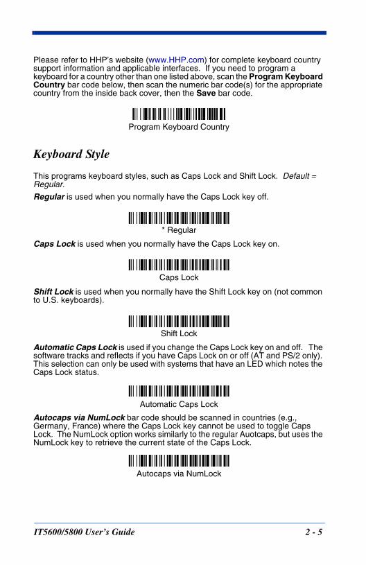
Please refer to HHP’s website (www.HHP.com) for complete keyboard country support information and applicable interfaces. If you need to program a keyboard for a country other than one listed above, scan the Program Keyboard Country bar code below, then scan the numeric bar code(s) for the appropriate country from the inside back cover, then the Save bar code.
Keyboard Style
This programs keyboard styles, such as Caps Lock and Shift Lock. Default = Regular.
Regular is used when you normally have the Caps Lock key off.
Caps Lock is used when you normally have the Caps Lock key on.
Shift Lock is used when you normally have the Shift Lock key on (not common to U.S. keyboards).
Automatic Caps Lock is used if you change the Caps Lock key on and off. The software tracks and reflects if you have Caps Lock on or off (AT and PS/2 only). This selection can only be used with systems that have an LED which notes the Caps Lock status.
Autocaps via NumLock bar code should be scanned in countries (e.g., Germany, France) where the Caps Lock key cannot be used to toggle Caps Lock. The NumLock option works similarly to the regular Auotcaps, but uses the NumLock key to retrieve the current state of the Caps Lock.
Program Keyboard Country
* Regular
Caps Lock
Shift Lock
Automatic Caps Lock
Autocaps via NumLock
IT5600/5800 User’s Guide 2 - 5
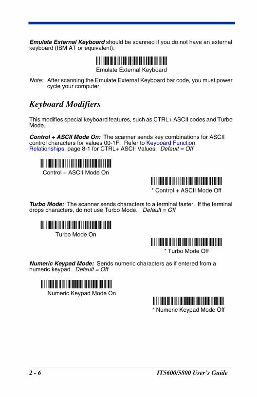
Emulate External Keyboard should be scanned if you do not have an external keyboard (IBM AT or equivalent).
Note: After scanning the Emulate External Keyboard bar code, you must power cycle your computer.
Keyboard Modifiers
This modifies special keyboard features, such as CTRL+ ASCII codes and Turbo Mode.
Control + ASCII Mode On: The scanner sends key combinations for ASCII control characters for values 00-1F. Refer to Keyboard Function Relationships, page 8-1 for CTRL+ ASCII Values. Default = Off
Turbo Mode: The scanner sends characters to a terminal faster. If the terminal drops characters, do not use Turbo Mode. Default = Off
Numeric Keypad Mode: Sends numeric characters as if entered from a numeric keypad. Default = Off
Emulate External Keyboard
Control + ASCII Mode On
* Control + ASCII Mode Off
Turbo Mode On
* Turbo Mode Off
Numeric Keypad Mode On
* Numeric Keypad Mode Off
2 - 6 IT5600/5800 User’s Guide
Automatic Direct Connect Mode: This selection can be used if you have an IBM AT style terminal and the system is dropping characters. Default = Off
Automatic Direct Connect Mode On
* Automatic Direct Connect Mode Off
IT5600/5800 User’s Guide 2 - 7
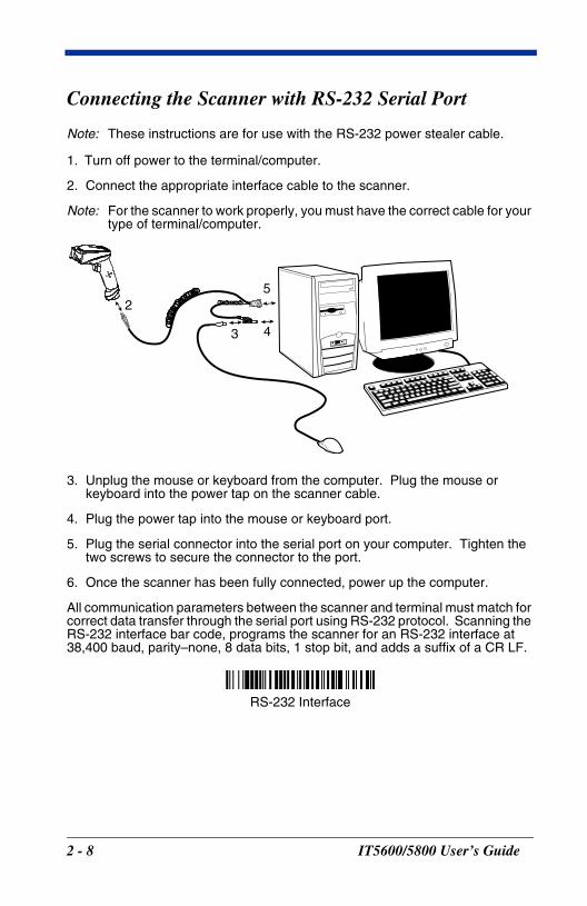
Connecting the Scanner with RS-232 Serial Port
Note: These instructions are for use with the RS-232 power stealer cable.
1. Turn off power to the terminal/computer.
2. Connect the appropriate interface cable to the scanner.
Note: For the scanner to work properly, you must have the correct cable for your type of terminal/computer.
3. Unplug the mouse or keyboard from the computer. Plug the mouse or keyboard into the power tap on the scanner cable.
4. Plug the power tap into the mouse or keyboard port.
5. Plug the serial connector into the serial port on your computer. Tighten the two screws to secure the connector to the port.
6. Once the scanner has been fully connected, power up the computer.
All communication parameters between the scanner and terminal must match for correct data transfer through the serial port using RS-232 protocol. Scanning the RS-232 interface bar code, programs the scanner for an RS-232 interface at 38,400 baud, parity–none, 8 data bits, 1 stop bit, and adds a suffix of a CR LF.
3 4
52
RS-232 Interface
2 - 8 IT5600/5800 User’s Guide
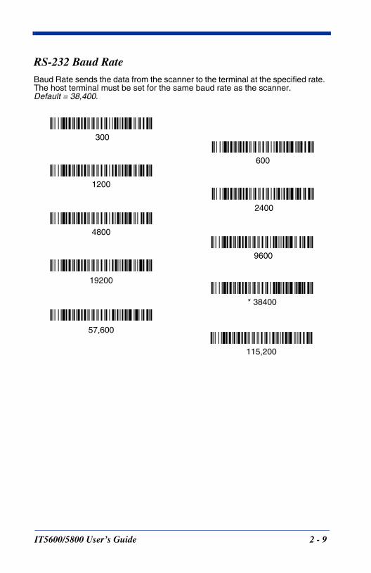
RS-232 Baud RateBaud Rate sends the data from the scanner to the terminal at the specified rate. The host terminal must be set for the same baud rate as the scanner. Default = 38,400.
300
2400
600
1200
4800
* 38400
9600
19200
115,200
57,600
IT5600/5800 User’s Guide 2 - 9
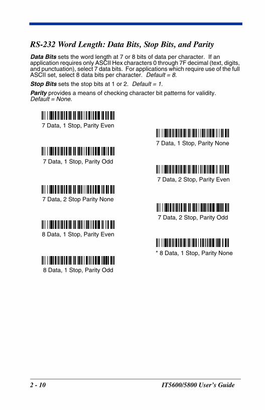
RS-232 Word Length: Data Bits, Stop Bits, and ParityData Bits sets the word length at 7 or 8 bits of data per character. If an application requires only ASCII Hex characters 0 through 7F decimal (text, digits, and punctuation), select 7 data bits. For applications which require use of the full ASCII set, select 8 data bits per character. Default = 8.
Stop Bits sets the stop bits at 1 or 2. Default = 1.
Parity provides a means of checking character bit patterns for validity.Default = None.
7 Data, 1 Stop, Parity Even
7 Data, 1 Stop, Parity None
7 Data, 1 Stop, Parity Odd
7 Data, 2 Stop, Parity Odd
7 Data, 2 Stop, Parity Even
7 Data, 2 Stop Parity None
* 8 Data, 1 Stop, Parity None
8 Data, 1 Stop, Parity Even
8 Data, 1 Stop, Parity Odd
2 - 10 IT5600/5800 User’s Guide
RS-232 HandshakingRS-232 handshaking is a set of rules concerning the exchange of data between serially communicating devices. Default = RTS/CTS, XON/XOFF and ACK/NAK Off
Wand Emulation ConnectionThe Wand Emulation Connection bar codes should be used if you want to change the terminal ID only, without changing any other imager settings. We recommend using Wand Emulation Plug & Play bar codes to program your imager to emulate a wand reader. The Wand Emulation Plug & Play bar codes change other parameters, in addition to changing the terminal ID. Please refer to Wand Emulation Plug & Play on page 1-7 for further information.
In Wand Emulation mode, the imager decodes the bar code then sends data in the same format as a wand imager. The Code 39 Format converts all symbologies to Code 39.
The Same Code Format transmits UPC, EAN, Code 128 and Interleaved 2 of 5 without any changes, but converts all other symbologies to Code 39. 2D symbologies are converted to Code 128.
The Code 39 Format bar code below sets the terminal ID to 61, and the Same Code Format bar code sets the terminal ID to 64.
RTS/CTS On
* XON/OFF Off
* RTS/CTS Off
XON/XOFF On
ACK/NAK On
* ACK/NAK Off
Code 39 Format
Same Code Format
IT5600/5800 User’s Guide 2 - 11
Wand Emulation Transmission RateThe transmission rate is limited by the terminal’s ability to receive data without dropping characters. Default = 25 inches/second.
Wand Emulation PolarityThe Polarity can be sent as standard with black bars high, or reversed with white bars high. Default = Black High.
10
80
* 25
40
120
150
200
* Black High
White High
2 - 12 IT5600/5800 User’s Guide
Wand Emulation IdleThe idle describes the state of the scanner when no data is being transmitted. When in Wand Emulation mode, you must set the scanner’s idle state to match the idle state for the device to which the scanner is connected. Default = Idle High.
Wand Emulation
Note: Changing primary wand emulation settings also changes the secondary wand emulation settings (see Secondary Code 39 Wand Emulation on page 6-2).
Data Block Size
Note: This option is not applicable to Laser Emulation Raw Output (see Secondary Laser Emulation on page 6-3).
This transmits the data in smaller blocks to prevent buffer overflow. Default = 60.
* Idle High
Idle Low
20
80
40
* 60
IT5600/5800 User’s Guide 2 - 13
Delay Between Blocks
Note: This option is not applicable to Laser Emulation Raw Output (see Secondary Laser Emulation on page 6-3).
This sets the delay time between data blocks. Default = 50ms.
Overall Checksum
Note: This option is not applicable to Laser Emulation Raw Output (see Secondary Laser Emulation on page 6-3).
When this option is turned on, a computed check character is added at the end of the entire message. The check character is the character which when Exclusive-OR’d with every preceding character of the message yields a result of 0x00 (00H). Default = Off.
5ms
500ms
* 50ms
150ms
On
* Off
2 - 14 IT5600/5800 User’s Guide
3O
IT560
utput
Good Read Indicators
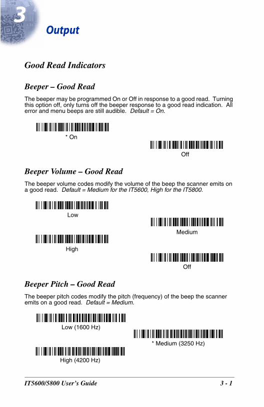
Beeper – Good ReadThe beeper may be programmed On or Off in response to a good read. Turning this option off, only turns off the beeper response to a good read indication. All error and menu beeps are still audible. Default = On.
Beeper Volume – Good ReadThe beeper volume codes modify the volume of the beep the scanner emits on a good read. Default = Medium for the IT5600, High for the IT5800.
Beeper Pitch – Good ReadThe beeper pitch codes modify the pitch (frequency) of the beep the scanner emits on a good read. Default = Medium.
* On
Off
High
Medium
Off
Low
Low (1600 Hz)
* Medium (3250 Hz)
High (4200 Hz)
0/5800 User’s Guide 3 - 1
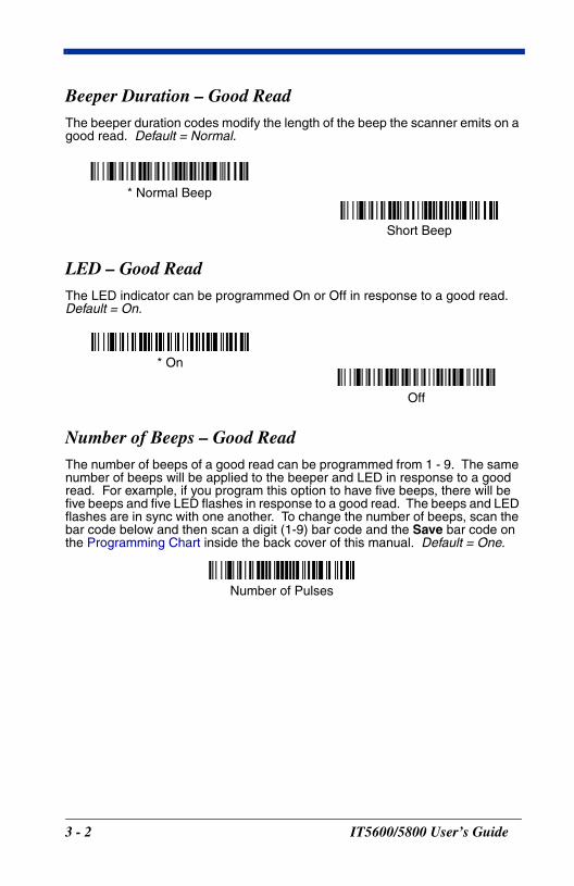
Beeper Duration – Good ReadThe beeper duration codes modify the length of the beep the scanner emits on a good read. Default = Normal.
LED – Good ReadThe LED indicator can be programmed On or Off in response to a good read. Default = On.
Number of Beeps – Good ReadThe number of beeps of a good read can be programmed from 1 - 9. The same number of beeps will be applied to the beeper and LED in response to a good read. For example, if you program this option to have five beeps, there will be five beeps and five LED flashes in response to a good read. The beeps and LED flashes are in sync with one another. To change the number of beeps, scan the bar code below and then scan a digit (1-9) bar code and the Save bar code on the Programming Chart inside the back cover of this manual. Default = One.
* Normal Beep
Short Beep
* On
Off
Number of Pulses
3 - 2 IT5600/5800 User’s Guide
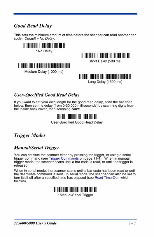
Good Read Delay
This sets the minimum amount of time before the scanner can read another bar code. Default = No Delay.
User-Specified Good Read DelayIf you want to set your own length for the good read delay, scan the bar code below, then set the delay (from 0-30,000 milliseconds) by scanning digits from the inside back cover, then scanning Save.
Trigger Modes
Manual/Serial TriggerYou can activate the scanner either by pressing the trigger, or using a serial trigger command (see Trigger Commands on page 11-4). When in manual trigger mode, the scanner scans until a bar code is read, or until the trigger is released.
When in serial mode, the scanner scans until a bar code has been read or until the deactivate command is sent. In serial mode, the scanner can also be set to turn itself off after a specified time has elapsed (see Read Time-Out, which follows).
* No Delay
Short Delay (500 ms)
Medium Delay (1000 ms)
Long Delay (1500 ms)
User-Specified Good Read Delay
* Manual/Serial Trigger
IT5600/5800 User’s Guide 3 - 3
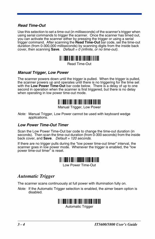
Read Time-Out
Use this selection to set a time-out (in milliseconds) of the scanner’s trigger when using serial commands to trigger the scanner. Once the scanner has timed out, you can activate the scanner either by pressing the trigger or using a serial trigger command. After scanning the Read Time-Out bar code, set the time-out duration (from 0-300,000 milliseconds) by scanning digits from the inside back cover, then scanning Save. Default = 0 (infinite, or no time-out).
Manual Trigger, Low Power
The scanner powers down until the trigger is pulled. When the trigger is pulled, the scanner powers up and operates until there is no triggering for the time set with the Low Power Time-Out bar code below. There is a delay of up to one second in operation when the scanner is first triggered, but there is no delay when operating in low power time-out mode.
Note: Manual Trigger, Low Power cannot be used with keyboard wedge applications.
Low Power Time-Out Timer
Scan the Low Power Time-Out bar code to change the time-out duration (in seconds). Then scan the time-out duration (from 0-300 seconds) from the inside back cover, and Save. Default = 120 seconds.
If there are no trigger pulls during the “low power time-out timer” interval, the scanner goes in low power mode. Whenever the trigger is enabled, the “low power time-out timer” is reset.
Automatic TriggerThe scanner scans continuously at full power with illumination fully on.
Note: If the Automatic Trigger selection is enabled, the aimer beam option is disabled.
Read Time-Out
Manual Trigger, Low Power
Low Power Time-Out
Automatic Trigger
3 - 4 IT5600/5800 User’s Guide
Presentation ModeNote: Presentation mode does not work when a scanner is programmed for the
laser emulation interface.
Note: If the Presentation Mode selection is enabled, the aimer beam option is disabled.
The LEDs are off until a bar code is presented to the scanner. Then the LEDs turn on automatically to read the code. Presentation Mode uses ambient light to detect the bar codes. If the light level in the room is not high enough, Presentation Mode will not work properly.
Hands Free Time-Out
The Automatic Trigger and Presentation Modes are referred to as “hands free” modes. If the imager’s trigger is pulled when using a hands free mode, the imager changes to manual trigger mode. You can set the time the imager should remain in manual trigger mode by setting the Hands Free Time-Out. Once the time-out value is reached, (if there have been no further trigger pulls) the imager reverts to the original hands free mode.
Scan the Hands Free Time-Out bar code, then scan the time-out duration (from 0-300,000 milliseconds) from the inside back cover, and Save. Default = 5,000 ms.
Reread Delay
This sets the time period before the scanner can read the same bar code a second time. Setting a reread delay protects against accidental rereads of the same bar code. Longer delays are effective in minimizing accidental rereads at POS (point of sale). Use shorter delays in applications where repetitive bar code scanning is required. Default = Medium.
Presentation Mode
Hands Free Time-Out
IT5600/5800 User’s Guide 3 - 5

Reread Delay only works when in automatic trigger mode (see page 3-4).
User-Specified Reread DelayIf you want to set your own length for the reread delay, scan the bar code below, then set the delay (from 0-30,000 milliseconds) by scanning digits from the inside back cover, then scanning Save.
Short (500 ms)
* Medium (750 ms)
Long (1000 ms)
Extra Long (2000 ms)
User-Specified Reread Delay
3 - 6 IT5600/5800 User’s Guide
Aimer Beam Delay (Aimer Beam option only)
The Aimer Beam Delay allows a delay time for the operator to aim the reader before the standard illumination and decoding starts. The quickset codes sets the time between when the trigger is pulled and when the decode starts to either 1 or 2 seconds. During the delay time, the aiming beam appears, but the illumination LEDs won’t turn on until the delay time is over.
User-Specified Aimer Beam DelayIf you want to set your own length for the duration of the delay, scan the bar code below, then set the time-out by scanning digits (0 - 4000 ms) from the Programming Chart inside the back cover of this manual and then scan Save.
Aimer Mode (Aimer Beam option only)
If you are reading codes in applications that exhibit high ambient light, you can turn on the aimer beam to assist you in reliably finding and scanning a code. Select Off if you don’t want to use the aimer beam.
2 seconds
1 second
* Off (no delay)
Delay Duration
Off
* On
IT5600/5800 User’s Guide 3 - 7
Aimer Beam Time-Out (Aimer Beam option only)
Aimer Beam Time-Out powers down the aimer beam after a time-out if the trigger is still pulled and there isn’t a valid decode. Scan the bar code below, then set the time-out by scanning digits (from 0 - 240,000 ms) from the Programming Chart inside the back cover of this manual and then scan Save. Default = 0 (no time-out)
Centering Window
Use the centering feature to narrow the scanner’s field of view so the scanner reads only the bar code you want. When centering is turned on, the scanner only reads codes that intersect or are contained within the centering window you set up. At least part of a bar code must be within the window to be decoded or output by the scanner.
To change the left or right edge of the centering window, scan Centering On, then scan one of the following bar codes. Then scan the percent you want to shift the centering window using digits on the inside back cover of this manual. Scan Save. Default Centering = 40% for Left, 60% for Right.
Time-Out Duration
Left of Centering Window
Right of Centering Window
* Centering Off
Centering On
3 - 8 IT5600/5800 User’s Guide
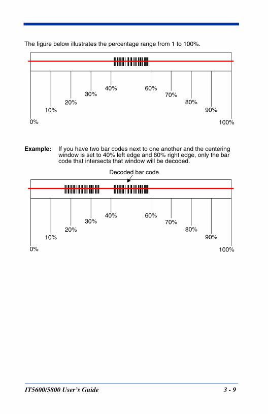
The figure below illustrates the percentage range from 1 to 100%.
Example: If you have two bar codes next to one another and the centering window is set to 40% left edge and 60% right edge, only the bar code that intersects that window will be decoded.
20%30%
90%80%
40% 60%70%
10%
0% 100%
20%30%
90%80%
40% 60%70%
10%
0% 100%
Decoded bar code
IT5600/5800 User’s Guide 3 - 9
Output Sequence Overview
Require Output Sequence
When turned off, the bar code data will be output to the host as the scanner decodes it. When turned on, all output data must conform to an edited sequence or the scanner will not transmit the output data to the host device.
Note: This selection is unavailable when the Multiple Symbols Selection is turned on.
Output Sequence Editor
This programming selection allows you to program the scanner to output data (when scanning more than one symbol) in whatever order your application requires, regardless of the order in which the bar codes are scanned. Reading the Default Sequence symbol programs the scanner to the Universal values, shown below. These are the defaults. Be certain you want to delete or clear all formats before you read the Default Sequence symbol.
Note: To make Output Sequence Editor selections, you’ll need to know the code I.D., code length, and character match(es) your application requires. Use the Alphanumeric symbols (inside back cover) to read these options.
To Add an Output Sequence
1. Scan the Enter Sequence symbol (see Multiple Symbols, page 3-13).
2. Code I.D.On the Symbology Chart on page A-1, find the symbology to which you want to apply the output sequence format. Locate the Hex value for that symbol-ogy and scan the 2 digit hex value from the Programming Chart (inside back cover).
3. LengthSpecify what length (up to 9999 characters) of data output will be acceptable for this symbology. Scan the four digit data length from the Programming Chart. (Note: 50 characters is entered as 0050. 9999 is a universal num-ber, indicating all lengths.)
4. Character Match SequencesOn the ASCII Conversion Chart (Code Page 1252), page A-3, find the Hex value that represents the character(s) you want to match. Use the Program-ming Chart to read the alphanumeric combination that represents the ASCII characters. (99 is the Universal number, indicating all characters.)
5. End Output Sequence EditorScan F F to enter an Output Sequence for an additional symbology, or Save to save your entries.
Other Programming Selections
• Discard This exits without saving any Output Sequence changes.
3 - 10 IT5600/5800 User’s Guide
Output Sequence Editor
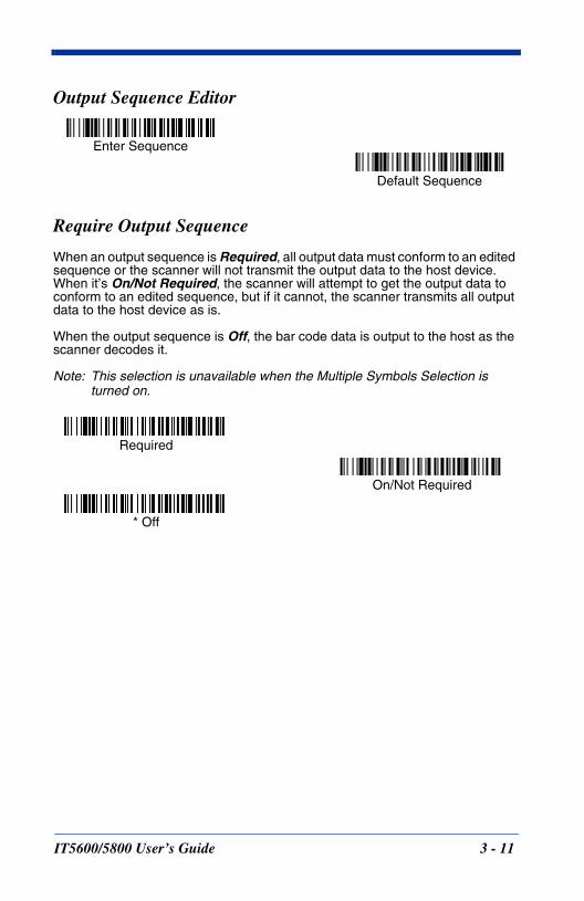
Require Output Sequence
When an output sequence is Required, all output data must conform to an edited sequence or the scanner will not transmit the output data to the host device. When it’s On/Not Required, the scanner will attempt to get the output data to conform to an edited sequence, but if it cannot, the scanner transmits all output data to the host device as is.
When the output sequence is Off, the bar code data is output to the host as the scanner decodes it.
Note: This selection is unavailable when the Multiple Symbols Selection is turned on.
Enter Sequence
Default Sequence
Required
On/Not Required
* Off
IT5600/5800 User’s Guide 3 - 11
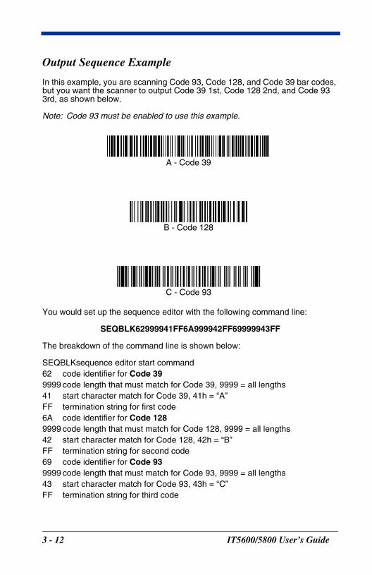
Output Sequence Example
In this example, you are scanning Code 93, Code 128, and Code 39 bar codes, but you want the scanner to output Code 39 1st, Code 128 2nd, and Code 93 3rd, as shown below.
Note: Code 93 must be enabled to use this example.
You would set up the sequence editor with the following command line:
SEQBLK62999941FF6A999942FF69999943FF
The breakdown of the command line is shown below:
SEQBLKsequence editor start command62 code identifier for Code 399999 code length that must match for Code 39, 9999 = all lengths41 start character match for Code 39, 41h = “A”FF termination string for first code6A code identifier for Code 1289999 code length that must match for Code 128, 9999 = all lengths42 start character match for Code 128, 42h = “B”FF termination string for second code69 code identifier for Code 939999 code length that must match for Code 93, 9999 = all lengths43 start character match for Code 93, 43h = “C”FF termination string for third code
A - Code 39
B - Code 128
C - Code 93
3 - 12 IT5600/5800 User’s Guide
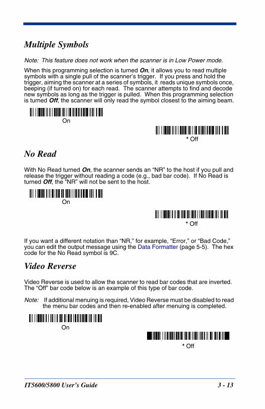
Multiple Symbols
Note: This feature does not work when the scanner is in Low Power mode.
When this programming selection is turned On, it allows you to read multiple symbols with a single pull of the scanner’s trigger. If you press and hold the trigger, aiming the scanner at a series of symbols, it reads unique symbols once, beeping (if turned on) for each read. The scanner attempts to find and decode new symbols as long as the trigger is pulled. When this programming selection is turned Off, the scanner will only read the symbol closest to the aiming beam.
No Read
With No Read turned On, the scanner sends an “NR” to the host if you pull and release the trigger without reading a code (e.g., bad bar code). If No Read is turned Off, the “NR” will not be sent to the host.
If you want a different notation than “NR,” for example, “Error,” or “Bad Code,” you can edit the output message using the Data Formatter (page 5-5). The hex code for the No Read symbol is 9C.
Video Reverse
Video Reverse is used to allow the scanner to read bar codes that are inverted. The “Off” bar code below is an example of this type of bar code.
Note: If additional menuing is required, Video Reverse must be disabled to read the menu bar codes and then re-enabled after menuing is completed.
On
* Off
On
* Off
On
* Off
IT5600/5800 User’s Guide 3 - 13

3 - 14 IT5600/5800 User’s Guide
4D
IT560
ata Editing
Prefix/Suffix Overview
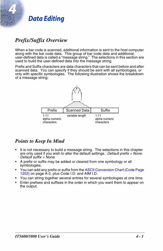
When a bar code is scanned, additional information is sent to the host computer along with the bar code data. This group of bar code data and additional, user-defined data is called a “message string.” The selections in this section are used to build the user-defined data into the message string.
Prefix and Suffix characters are data characters that can be sent before and after scanned data. You can specify if they should be sent with all symbologies, or only with specific symbologies. The following illustration shows the breakdown of a message string:
Points to Keep In Mind
• It is not necessary to build a message string. The selections in this chapter are only used if you wish to alter the default settings. Default prefix = None. Default suffix = None.
• A prefix or suffix may be added or cleared from one symbology or all symbologies.
• You can add any prefix or suffix from the ASCII Conversion Chart (Code Page 1252) on page A-2, plus Code I.D. and AIM I.D.
• You can string together several entries for several symbologies at one time.• Enter prefixes and suffixes in the order in which you want them to appear on
the output.
Prefix Scanned Data Suffix1-11alpha numeric characters
variable length 1-11alpha numeric characters
0/5800 User’s Guide 4 - 1
To Add a Prefix or Suffix:
Step 1. Scan the Add Prefix or Add Suffix symbol (page 4-3).
Step 2. Determine the 2 digit Hex value from the Symbology Chart (included in the Appendix A) for the symbology to which you want to apply the prefix or suffix. For example, for Code 128, Code ID is “j” and Hex ID is “6A”.
Step 3. Scan the 2 hex digits from the Programming Chart inside the back cover of this manual or scan 9, 9 for all symbologies.
Step 4. Determine the hex value from the ASCII Conversion Chart (Code Page 1252) on page A-2, for the prefix or suffix you wish to enter.
Step 5. Scan the 2 digit hex value from the Programming Chart inside the back cover of this manual.
Step 6. Repeat Steps 4 and 5 for every prefix or suffix character.
Step 7. To add the Code I.D., scan 5, C, 8, 0. To add AIM I.D., scan 5, C, 8, 1. To add a backslash (\), scan 5, C, 5, C.
Note: To add a backslash (\) as in Step 7, you must scan 5C twice – once to create the leading backslash and then to create the backslash itself.
Step 8. Scan Save to exit and save, or scan Discard to exit without saving.
Repeat Steps 1-6 to add a prefix or suffix for another symbology.
Example: Add a Suffix to a specific symbology
To send a CR (carriage return)Suffix for UPC only:
Step 1. Scan Add Suffix.
Step 2. Determine the 2 digit hex value from the Symbology Chart (included in the Appendix A) for UPC.
Step 3. Scan 6, 3 from the Programming Chart inside the back cover of this manual.
Step 4. Determine the hex value from the ASCII Conversion Chart (Code Page 1252) on page A-2, for the CR (carriage return).
Step 5. Scan 0, D from the Programming Chart inside the back cover of this manual.
Step 6. Scan Save, or scan Discard to exit without saving.
4 - 2 IT5600/5800 User’s Guide
To Clear One or All Prefixes or Suffixes:You can clear a single prefix or suffix, or clear all prefixes/suffixes for a symbology. When you Clear One Prefix (Suffix), the specific character you select is deleted from the symbology you want. When you Clear All Prefixes (Suffixes), all the prefixes or suffixes for a symbology are deleted.
Step 1. Scan the Clear One Prefix or Clear One Suffix symbol.
Step 2. Determine the 2 digit Hex value from the Symbology Chart (included in the Appendix A) for the symbology from which you want to clear the pre-fix or suffix.
Step 3. Scan the 2 digit hex value from the Programming Chart inside the back cover of this manual or scan 9, 9 for all symbologies.
Your change is automatically saved.
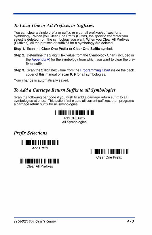
To Add a Carriage Return Suffix to all SymbologiesScan the following bar code if you wish to add a carriage return suffix to all symbologies at once. This action first clears all current suffixes, then programs a carriage return suffix for all symbologies.
Prefix Selections
Add CR SuffixAll Symbologies
Add Prefix
Clear One Prefix
Clear All Prefixes
IT5600/5800 User’s Guide 4 - 3
Suffix Selections
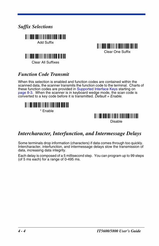
Function Code TransmitWhen this selection is enabled and function codes are contained within the scanned data, the scanner transmits the function code to the terminal. Charts of these function codes are provided in Supported Interface Keys starting on page 8-3. When the scanner is in keyboard wedge mode, the scan code is converted to a key code before it is transmitted. Default = Enable.
Intercharacter, Interfunction, and Intermessage Delays
Some terminals drop information (characters) if data comes through too quickly. Intercharacter, interfunction, and intermessage delays slow the transmission of data, increasing data integrity.
Each delay is composed of a 5 millisecond step. You can program up to 99 steps (of 5 ms each) for a range of 0-495 ms.
Add Suffix
Clear One Suffix
Clear All Suffixes
* Enable
Disable
4 - 4 IT5600/5800 User’s Guide
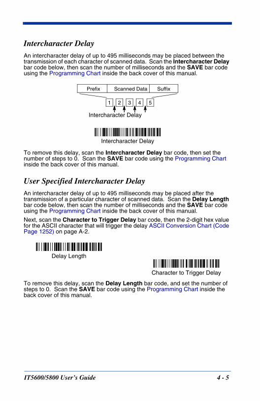
Intercharacter DelayAn intercharacter delay of up to 495 milliseconds may be placed between the transmission of each character of scanned data. Scan the Intercharacter Delay bar code below, then scan the number of milliseconds and the SAVE bar code using the Programming Chart inside the back cover of this manual.
To remove this delay, scan the Intercharacter Delay bar code, then set the number of steps to 0. Scan the SAVE bar code using the Programming Chart inside the back cover of this manual.
User Specified Intercharacter DelayAn intercharacter delay of up to 495 milliseconds may be placed after the transmission of a particular character of scanned data. Scan the Delay Length bar code below, then scan the number of milliseconds and the SAVE bar code using the Programming Chart inside the back cover of this manual.
Next, scan the Character to Trigger Delay bar code, then the 2-digit hex value for the ASCII character that will trigger the delay ASCII Conversion Chart (Code Page 1252) on page A-2.
To remove this delay, scan the Delay Length bar code, and set the number of steps to 0. Scan the SAVE bar code using the Programming Chart inside the back cover of this manual.
1 2 3 4 5
Intercharacter Delay
Prefix Scanned Data Suffix
Intercharacter Delay
Delay Length
Character to Trigger Delay
IT5600/5800 User’s Guide 4 - 5
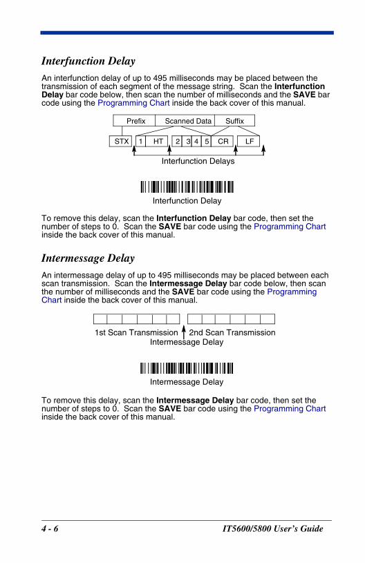
Interfunction DelayAn interfunction delay of up to 495 milliseconds may be placed between the transmission of each segment of the message string. Scan the Interfunction Delay bar code below, then scan the number of milliseconds and the SAVE bar code using the Programming Chart inside the back cover of this manual.
To remove this delay, scan the Interfunction Delay bar code, then set the number of steps to 0. Scan the SAVE bar code using the Programming Chart inside the back cover of this manual.
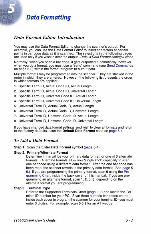
Intermessage DelayAn intermessage delay of up to 495 milliseconds may be placed between each scan transmission. Scan the Intermessage Delay bar code below, then scan the number of milliseconds and the SAVE bar code using the Programming Chart inside the back cover of this manual.
To remove this delay, scan the Intermessage Delay bar code, then set the number of steps to 0. Scan the SAVE bar code using the Programming Chart inside the back cover of this manual.
Interfunction Delays
Prefix Scanned Data Suffix
1 2 3 4 5STX HT CR LF
Interfunction Delay
2nd Scan Transmission1st Scan TransmissionIntermessage Delay
Intermessage Delay
4 - 6 IT5600/5800 User’s Guide
5D
IT560
ata Formatting
Data Format Editor Introduction
You may use the Data Format Editor to change the scanner’s output. For example, you can use the Data Format Editor to insert characters at certain points in bar code data as it is scanned. The selections in the following pages are used only if you wish to alter the output. Default Data Format setting = None.
Normally, when you scan a bar code, it gets outputted automatically; however when you do a format, you must use a “send” command (see Send Commands on page 5-2) within the format program to output data.
Multiple formats may be programmed into the scanner. They are stacked in the order in which they are entered. However, the following list presents the order in which formats are applied:
1. Specific Term ID, Actual Code ID, Actual Length
2. Specific Term ID, Actual Code ID, Universal Length3. Specific Term ID, Universal Code ID, Actual Length
4. Specific Term ID, Universal Code ID, Universal Length
5. Universal Term ID, Actual Code ID, Actual Length
6. Universal Term ID, Actual Code ID, Universal Length7. Universal Term ID, Universal Code ID, Actual Length
8. Universal Term ID, Universal Code ID, Universal Length
If you have changed data format settings, and wish to clear all formats and return to the factory defaults, scan the Default Data Format code on page 5-4.
To Add a Data FormatStep 1. Scan the Enter Data Format symbol (page 5-4).
Step 2. Primary/Alternate FormatDetermine if this will be your primary data format, or one of 3 alternate formats. (Alternate formats allow you “single shot” capability to scan one bar code using a different data format. After the one bar code has been read, the scanner reverts to the primary data format. See page 5-5.) If you are programming the primary format, scan 0 using the Pro-gramming Chart inside the back cover of this manual. If you are pro-gramming an alternate format, scan 1, 2, or 3, depending on the alternate format you are programming.
Step 3. Terminal TypeRefer to the Supported Terminals Chart (page 2-2) and locate the Ter-minal ID number for your PC. Scan three numeric bar codes on the inside back cover to program the scanner for your terminal ID (you must enter 3 digits). For example, scan 0 0 3 for an AT wedge.
0/5800 User’s Guide 5 - 1
Note: The wildcard for all terminal types is 099.
Step 4. Code I.D.In the Appendix A, find the symbology to which you want to apply the data format. Locate the Hex value for that symbology and scan the 2 digit hex value from the Programming Chart inside the back cover of this manual.
Step 5. LengthSpecify what length (up to 9999 characters) of data will be acceptable for this symbology. Scan the four digit data length from the Program-ming Chart inside the back cover of this manual. (Note: 50 characters is entered as 0050. 9999 is a universal number, indicating all lengths.)
Step 6. Editor CommandsRefer to the Format Editor Commands Chart (page 5-2). Scan the sym-bols that represent the command you want to enter. 94 alphanumeric characters may be entered for each symbology data format.
Step 7. Scan Save from the Programming Chart inside the back cover of this manual to save your entries.
Other Programming Selections• Clear One Data Format
This deletes one data format for one symbology. If you are clearing the primary format, scan 0 from the Programming Chart inside the back cover of this manual. If you are clearing an alternate format, scan 1, 2, or 3, depending on the alternate format you are clearing. Scan the Terminal Type (refer to the Supported Terminals Chart on page 2-2), Code I.D. (refer to the Symbology Chart on page A-1), and the bar code data length for the specific data format that you want to delete. All other formats remain unaffected.
• Save from the Programming Chart inside the back cover of this manualThis exits, saving any Data Format changes.
• Discard from the Programming Chart inside the back cover of this manualThis exits without saving any Data Format changes.
Data Format Editor Commands
Send CommandsF1 Send all characters followed by “xx” key or function code, starting from cur-
rent cursor position. Syntax = F1xx (xx stands for the hex value for an ASCII code, see ASCII Conversion Chart (Code Page 1252) on page A-2.)
F2 Send “nn” characters followed by “xx” key or function code, starting from current cursor position. Syntax = F2nnxx (nn stands for the numeric value (00-99) for the number of characters and xx stands for the hex value for an ASCII code. See ASCII Conversion Chart (Code Page 1252) on page A-2.)
F3 Send up to but not including “ss” character (Search and Send) starting from current cursor position, leaving cursor pointing to “ss” character followed by “xx” key or function code. Syntax = F3ssxx (ss and xx both stand for the
5 - 2 IT5600/5800 User’s Guide
hex values for ASCII codes, see ASCII Conversion Chart (Code Page 1252) on page A-2.)
F4 Send “xx” character “nn” times (Insert) leaving cursor in current cursor posi-tion. Syntax = F4xxnn (xx stands for the hex value for an ASCII code, see ASCII Conversion Chart (Code Page 1252) on page A-2, and nn is the numeric value (00-99) for the number of times it should be sent.)
E9 Send all but the last “nn” characters, starting from the current cursor posi-tion. Syntax = E9nn (nn is the numeric value (00-99) for the number of characters that will not be sent at the end of the message.)
Move CommandsF5 Move the cursor ahead “nn” characters from current cursor position.
Syntax = F5nn (nn stands for the numeric value (00-99) for the number of characters the cursor should be moved ahead.)
F6 Move the cursor back “nn” characters from current cursor position. Syntax = F6nn (nn stands for the numeric value (00-99) for the number of characters the cursor should be moved back.)
F7 Move the cursor to the beginning of the data string. Syntax = F7.EA Move the cursor to the end of the data string. Syntax = EA
Search CommandsF8 Search ahead for “xx” character from current cursor position, leaving cursor
pointing to “xx” character. Syntax = F8xx (xx stands for the hex value for an ASCII code, see ASCII Conversion Chart (Code Page 1252) on page A-2.)
F9 Search back for “xx” character from current cursor position, leaving cursor pointing to “xx” character. Syntax = F9xx (xx stands for the hex value for an ASCII code, see ASCII Conversion Chart (Code Page 1252) on page A-2.)
E6 Search ahead for the first non “xx” character from the current cursor posi-tion, leaving cursor pointing to non “xx” character. Syntax = E6xx (xx stands for the hex value for an ASCII code, see ASCII Conversion Chart (Code Page 1252) on page A-2.
E7 Search back for the first non “xx” character from the current cursor position, leaving cursor pointing to non “xx” character. Syntax = E7xx (xx stands for the hex value for an ASCII code, see ASCII Conversion Chart (Code Page 1252) on page A-2.)
Miscellaneous CommandsFB Suppress all occurrences of up to 15 different characters, starting at the cur-
rent cursor position, as the cursor is advanced by other commands. When the FC command is encountered, the suppress function is terminated. The cursor is not moved by the FB command. Syntax = FBnnxxyy . .zz where nn is a count of the number of suppressed characters in the list and xxyy .. zz is the list of characters to be suppressed. (xx stands for the hex value for an ASCII code, see ASCII Conversion Chart (Code Page 1252) on page A-2.)
FC Disables suppress filter and clear all suppressed characters. Syntax = FC.
IT5600/5800 User’s Guide 5 - 3
E4 Replaces up to 15 characters in the data string with user specified charac-ters. Replacement continues until the E5 command is encountered. Syn-tax = E4nnxx1xx2yy1yy2...zz1zz2 where nn is the total count of both characters to be replaced plus replacement characters; xx1 defines charac-ters to be replaced and xx2 defines replacement characters, continuing through zz1 and zz2.
E5 Terminates character replacement. Syntax = E5.FE Compare character in current cursor position to the character “xx.” If char-
acters are equal, increment cursor. If characters are not equal, no format match. Syntax = FExx (xx stands for the hex value for an ASCII code, see ASCII Conversion Chart (Code Page 1252) on page A-2.)
EC Check to make sure there is an ASCII number at the current cursor position. If character is not numeric, format is aborted. Syntax = EC.
ED Check to make sure there is a non-numeric ASCII character at the current cursor position. If character is numeric, format is aborted. Syntax = ED.
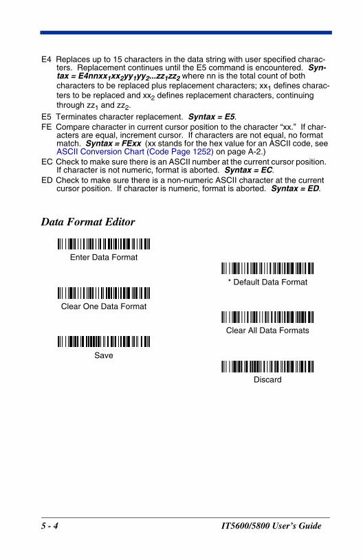
Data Format Editor
Enter Data Format
* Default Data Format
Clear One Data Format
Save
Discard
Clear All Data Formats
5 - 4 IT5600/5800 User’s Guide
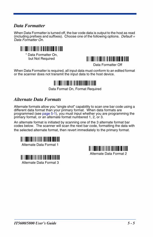
Data FormatterWhen Data Formatter is turned off, the bar code data is output to the host as read (including prefixes and suffixes). Choose one of the following options. Default = Data Formatter On.
When Data Formatter is required, all input data must conform to an edited format or the scanner does not transmit the input data to the host device.
Alternate Data FormatsAlternate formats allow you “single shot” capability to scan one bar code using a different data format than your primary format. When data formats are programmed (see page 5-1), you must input whether you are programming the primary format, or an alternate format numbered 1, 2, or 3.
An alternate format is initiated by scanning one of the 3 alternate format bar codes below. The scanner will scan the next bar code, formatting the data with the selected alternate format, then revert immediately to the primary format.
Data Formatter Off
* Data Formatter On,but Not Required
Data Format On, Format Required
Alternate Data Format 1
Alternate Data Format 2
Alternate Data Format 3
IT5600/5800 User’s Guide 5 - 5

5 - 6 IT5600/5800 User’s Guide
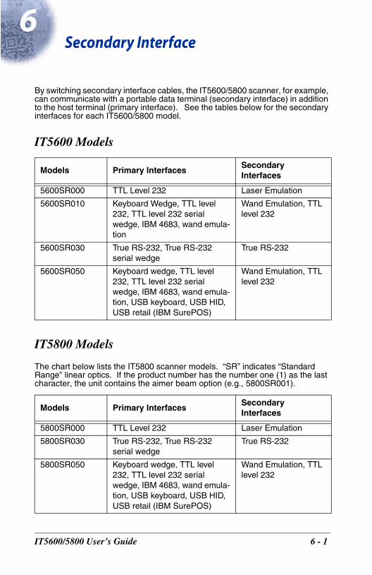
6S
IT560
econdary Interface
By switching secondary interface cables, the IT5600/5800 scanner, for example, can communicate with a portable data terminal (secondary interface) in addition to the host terminal (primary interface). See the tables below for the secondary interfaces for each IT5600/5800 model.
IT5600 Models
IT5800 Models
The chart below lists the IT5800 scanner models. “SR” indicates “Standard Range” linear optics. If the product number has the number one (1) as the last character, the unit contains the aimer beam option (e.g., 5800SR001).
Models Primary InterfacesSecondary Interfaces
5600SR000 TTL Level 232 Laser Emulation
5600SR010 Keyboard Wedge, TTL level 232, TTL level 232 serial wedge, IBM 4683, wand emula-tion
Wand Emulation, TTL level 232
5600SR030 True RS-232, True RS-232 serial wedge
True RS-232
5600SR050 Keyboard wedge, TTL level 232, TTL level 232 serial wedge, IBM 4683, wand emula-tion, USB keyboard, USB HID, USB retail (IBM SurePOS)
Wand Emulation, TTL level 232
Models Primary InterfacesSecondary Interfaces
5800SR000 TTL Level 232 Laser Emulation
5800SR030 True RS-232, True RS-232 serial wedge
True RS-232
5800SR050 Keyboard wedge, TTL level 232, TTL level 232 serial wedge, IBM 4683, wand emula-tion, USB keyboard, USB HID, USB retail (IBM SurePOS)
Wand Emulation, TTL level 232
0/5800 User’s Guide 6 - 1
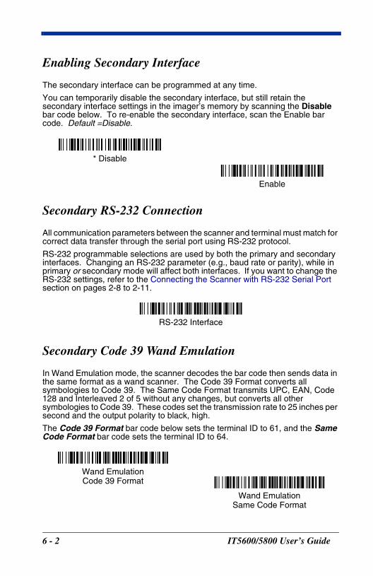
Enabling Secondary Interface
The secondary interface can be programmed at any time.
You can temporarily disable the secondary interface, but still retain the secondary interface settings in the imager’s memory by scanning the Disable bar code below. To re-enable the secondary interface, scan the Enable bar code. Default =Disable.
Secondary RS-232 Connection
All communication parameters between the scanner and terminal must match for correct data transfer through the serial port using RS-232 protocol.
RS-232 programmable selections are used by both the primary and secondary interfaces. Changing an RS-232 parameter (e.g., baud rate or parity), while in primary or secondary mode will affect both interfaces. If you want to change the RS-232 settings, refer to the Connecting the Scanner with RS-232 Serial Port section on pages 2-8 to 2-11.
Secondary Code 39 Wand Emulation
In Wand Emulation mode, the scanner decodes the bar code then sends data in the same format as a wand scanner. The Code 39 Format converts all symbologies to Code 39. The Same Code Format transmits UPC, EAN, Code 128 and Interleaved 2 of 5 without any changes, but converts all other symbologies to Code 39. These codes set the transmission rate to 25 inches per second and the output polarity to black, high.
The Code 39 Format bar code below sets the terminal ID to 61, and the Same Code Format bar code sets the terminal ID to 64.
* Disable
Enable
RS-232 Interface
Wand EmulationCode 39 Format
Wand EmulationSame Code Format
6 - 2 IT5600/5800 User’s Guide
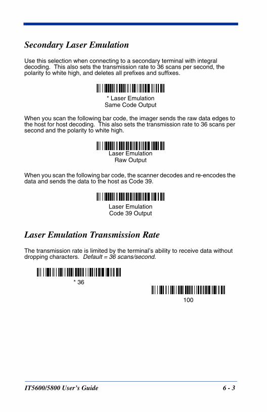
Secondary Laser Emulation
Use this selection when connecting to a secondary terminal with integral decoding. This also sets the transmission rate to 36 scans per second, the polarity to white high, and deletes all prefixes and suffixes.
When you scan the following bar code, the imager sends the raw data edges to the host for host decoding. This also sets the transmission rate to 36 scans per second and the polarity to white high.
When you scan the following bar code, the scanner decodes and re-encodes the data and sends the data to the host as Code 39.
Laser Emulation Transmission Rate
The transmission rate is limited by the terminal’s ability to receive data without dropping characters. Default = 36 scans/second.
* Laser EmulationSame Code Output
Laser EmulationRaw Output
Laser EmulationCode 39 Output
* 36
100
IT5600/5800 User’s Guide 6 - 3
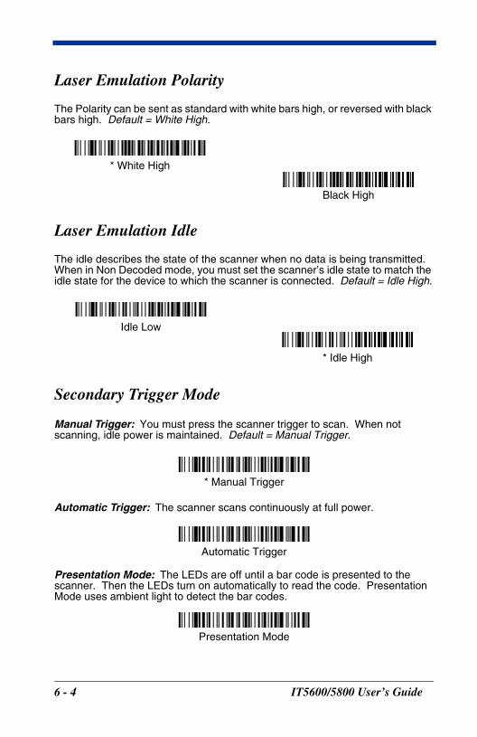
Laser Emulation Polarity
The Polarity can be sent as standard with white bars high, or reversed with black bars high. Default = White High.
Laser Emulation Idle
The idle describes the state of the scanner when no data is being transmitted. When in Non Decoded mode, you must set the scanner’s idle state to match the idle state for the device to which the scanner is connected. Default = Idle High.
Secondary Trigger Mode
Manual Trigger: You must press the scanner trigger to scan. When not scanning, idle power is maintained. Default = Manual Trigger.
Automatic Trigger: The scanner scans continuously at full power.
Presentation Mode: The LEDs are off until a bar code is presented to the scanner. Then the LEDs turn on automatically to read the code. Presentation Mode uses ambient light to detect the bar codes.
* White High
Black High
Idle Low
* Idle High
* Manual Trigger
Automatic Trigger
Presentation Mode
6 - 4 IT5600/5800 User’s Guide
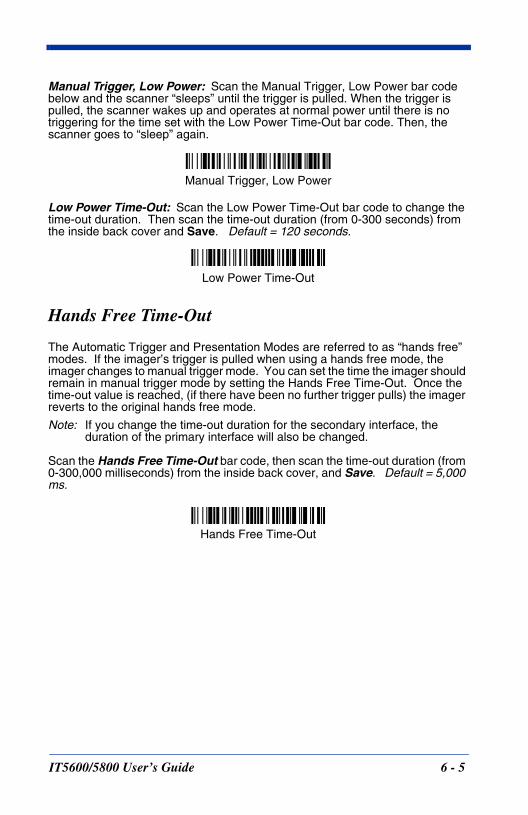
Manual Trigger, Low Power: Scan the Manual Trigger, Low Power bar code below and the scanner “sleeps” until the trigger is pulled. When the trigger is pulled, the scanner wakes up and operates at normal power until there is no triggering for the time set with the Low Power Time-Out bar code. Then, the scanner goes to “sleep” again.
Low Power Time-Out: Scan the Low Power Time-Out bar code to change the time-out duration. Then scan the time-out duration (from 0-300 seconds) from the inside back cover and Save. Default = 120 seconds.
Hands Free Time-Out
The Automatic Trigger and Presentation Modes are referred to as “hands free” modes. If the imager’s trigger is pulled when using a hands free mode, the imager changes to manual trigger mode. You can set the time the imager should remain in manual trigger mode by setting the Hands Free Time-Out. Once the time-out value is reached, (if there have been no further trigger pulls) the imager reverts to the original hands free mode.
Note: If you change the time-out duration for the secondary interface, the duration of the primary interface will also be changed.
Scan the Hands Free Time-Out bar code, then scan the time-out duration (from 0-300,000 milliseconds) from the inside back cover, and Save. Default = 5,000 ms.
Manual Trigger, Low Power
Low Power Time-Out
Hands Free Time-Out
IT5600/5800 User’s Guide 6 - 5

6 - 6 IT5600/5800 User’s Guide
7S
IT560
ymbologies
Introduction
This programming section contains the following menu selections. Refer to Chapter 11 for settings and defaults.
All Symbologies
If you want to decode all the symbologies allowable for your scanner, scan the All Symbologies On code. If on the other hand, you want to decode only a particular symbology, scan All Symbologies Off followed by the On symbol for that particular symbology.
• All Symbologies • IATA Code 2 of 5
• China Post • Interleaved 2 of 5
• Codabar • Korea Post
• Codablock F • Matrix 2 of 5
• Code 2 of 5 • Coupon Code
• Code 11 • MSI
• Code 16K • Plessey Code
• Code 39 • PosiCode
• Code 32 Pharmaceutical (PARAF) • RSS-14
• Code 49 • Telepen
• Code 93 • Trioptic
• Code 128 • UPC-A
• EAN/JAN • UPC-E
All Symbologies On
All Symbologies Off
0/5800 User’s Guide 7 - 1
Message Length
You are able to set the valid reading length of some of the bar code symbologies. If the data length of the scanned bar code doesn’t match the valid reading length, the scanner will issue an error beep. You may wish to set the same value for minimum and maximum length to force the scanner to read fixed length bar code data. This helps reduce the chances of a misread.
EXAMPLE:Decode only those bar codes with a count of 9-20 characters.Min. length = 09 Max. length = 20
EXAMPLE:Decode only those bar codes with a count of 15 characters.Min. length = 15 Max. length = 15
For a value other than the minimum and maximum message length defaults, scan the bar codes included in the explanation of the symbology, then scan the digit value of the message length and Save bar codes on the Programming Chart inside the back cover of this manual. The minimum and maximum lengths and the defaults are included with the respective symbologies.
7 - 2 IT5600/5800 User’s Guide
Codabar
<Default All Codabar Settings>
Codabar
Codabar Start/Stop CharactersStart/Stop characters identify the leading and trailing ends of the bar code. You may either transmit, or not transmit Start/Stop characters. Default = Don’t Transmit.
Codabar Check CharacterCodabar check characters are created using different “modulos.” You can program the scanner to read only Codabar bar codes with Modulo 16 check characters. Default = No Check Character.
No Check Character indicates that the scanner reads and transmits bar code data with or without a check character.
When Check Character is set to Validate and Transmit, the scanner will only read Codabar bar codes printed with a check character, and will transmit this character at the end of the scanned data.
* On
Off
Transmit
* Don’t Transmit
IT5600/5800 User’s Guide 7 - 3
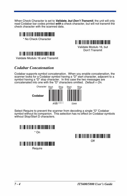
When Check Character is set to Validate, but Don’t Transmit, the unit will only read Codabar bar codes printed with a check character, but will not transmit the check character with the scanned data.
Codabar ConcatenationCodabar supports symbol concatenation. When you enable concatenation, the scanner looks for a Codabar symbol having a “D” start character, adjacent to a symbol having a “D” stop character. In this case the two messages are concatenated into one with the “D” characters omitted. Default = On.
Select Require to prevent the scanner from decoding a single “D” Codabar symbol without its companion. This selection has no effect on Codabar symbols without Stop/Start D characters.
* No Check Character
Validate Modulo 16 and Transmit
Validate Modulo 16, butDon’t Transmit
A12D D34A
Codabar
Character Stop Start StopStart
* On
Off
Require
7 - 4 IT5600/5800 User’s Guide
Codabar Message LengthScan the bar codes below to change the message length. Refer to Message Length on page 7-2 for additional information. Minimum and Maximumlengths = 2-60. Minimum Default = 4, Maximum Default = 60.
Code 39
< Default All Code 39 Settings >
Code 39
Code 39 Start/Stop CharactersStart/Stop characters identify the leading and trailing ends of the bar code. You may either transmit, or not transmit Start/Stop characters. Default = Don’t Transmit.
Minimum Message Length
Maximum Message Length
* On
Off
Transmit
* Don’t Transmit
IT5600/5800 User’s Guide 7 - 5
Code 39, continued
Code 39 Check CharacterNo Check Character indicates that the scanner reads and transmits bar code data with or without a check character.
When Check Character is set to Validate, but Don’t Transmit, the unit only reads Code 39 bar codes printed with a check character, but will not transmit the check character with the scanned data.
When Check Character is set to Validate and Transmit, the scanner only reads Code 39 bar codes printed with a check character, and will transmit this character at the end of the scanned data. Default = No Check Character.
Code 39 Message LengthScan the bar codes below to change the message length. Refer to Message Length on page 7-2 for additional information. Minimum and Maximumlengths = 0-48. Minimum Default = 0, Maximum Default = 48.
Validate, but Don’t Transmit
* No Check Character
Validate and Transmit
Minimum Message Length
Maximum Message Length
7 - 6 IT5600/5800 User’s Guide
Code 39, continued
Code 39 AppendThis function allows the scanner to append the data from several Code 39 bar codes together before transmitting them to the host computer. When this function is enabled, the scanner stores those Code 39 bar codes that start with a space (excluding the start and stop symbols), and does not immediately transmit the data. The scanner stores the data in the order in which the bar codes are read, deleting the first space from each. The scanner transmits the appended data when it reads a Code 39 bar code that starts with a character other than a space. Default = Off.
Code 32 Pharmaceutical (PARAF)Code 32 Pharmaceutical is a form of the Code 39 symbology used by Italian pharmacies. This symbology is also known as PARAF.
Note: Trioptic Code must be turned off to scan Code 32 Pharmaceutical codes.
* Off
On
* Off
On
IT5600/5800 User’s Guide 7 - 7
Full ASCIIIf Full ASCII Code 39 decoding is enabled, certain character pairs within the bar code symbol will be interpreted as a single character. For example: $V will be decoded as the ASCII character SYN, and /C will be decoded as the ASCII character #. Default = On.
Character pairs /M and /N decode as a minus sign and period respectively.Character pairs /P through /Y decode as 0 through 9.
NUL %U DLE $P SP SPACE 0 0 @ %V P P ‘ %W p +P
SOH $A DC1 $Q ! /A 1 1 A A Q Q a +A q +Q
STX $B DC2 $R “ /B 2 2 B B R R b +B r +R
ETX $C DC3 $S # /C 3 3 C C S S c +C s +S
EOT $D DC4 $T $ /D 4 4 D D T T d +D t +T
ENQ $E NAK $U % /E 5 5 E E U U e +E u +U
ACK $F SYN $V & /F 6 6 F F V V f +F v +V
BEL $G ETB $W ‘ /G 7 7 G G W W g +G w +W
BS $H CAN $X ( /H 8 8 H H X X h +H x +X
HT $I EM $Y ) /I 9 9 I I Y Y i +I y +Y
LF $J SUB $Z * /J : /Z J J Z Z j +J z +Z
VT $K ESC %A + /K ; %F K K [ %K k +K { %P
FF $L FS %B , /L < %G L L \ %L l +L | %Q
CR $M GS %C - - = %H M M ] %M m +M } %R
SO $N RS %D . . > %I N N ^ %N n +N ~ %S
SI $O US %E / /O ? %J O O _ %O o +O DEL %T
Full ASCII Off
* Full ASCII On
7 - 8 IT5600/5800 User’s Guide
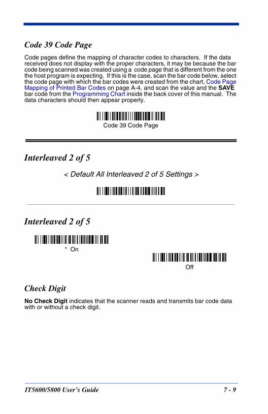
Code 39 Code PageCode pages define the mapping of character codes to characters. If the data received does not display with the proper characters, it may be because the bar code being scanned was created using a code page that is different from the one the host program is expecting. If this is the case, scan the bar code below, select the code page with which the bar codes were created from the chart, Code Page Mapping of Printed Bar Codes on page A-4, and scan the value and the SAVE bar code from the Programming Chart inside the back cover of this manual. The data characters should then appear properly.
Interleaved 2 of 5
< Default All Interleaved 2 of 5 Settings >
Interleaved 2 of 5
Check DigitNo Check Digit indicates that the scanner reads and transmits bar code data with or without a check digit.
Code 39 Code Page
* On
Off
IT5600/5800 User’s Guide 7 - 9
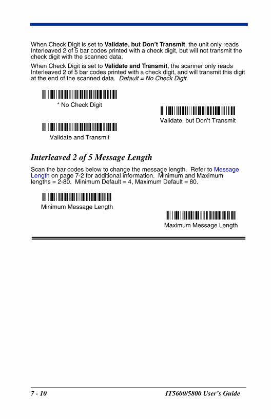
When Check Digit is set to Validate, but Don’t Transmit, the unit only reads Interleaved 2 of 5 bar codes printed with a check digit, but will not transmit the check digit with the scanned data.
When Check Digit is set to Validate and Transmit, the scanner only reads Interleaved 2 of 5 bar codes printed with a check digit, and will transmit this digit at the end of the scanned data. Default = No Check Digit.
Interleaved 2 of 5 Message LengthScan the bar codes below to change the message length. Refer to Message Length on page 7-2 for additional information. Minimum and Maximumlengths = 2-80. Minimum Default = 4, Maximum Default = 80.
Validate, but Don’t Transmit
* No Check Digit
Validate and Transmit
Minimum Message Length
Maximum Message Length
7 - 10 IT5600/5800 User’s Guide
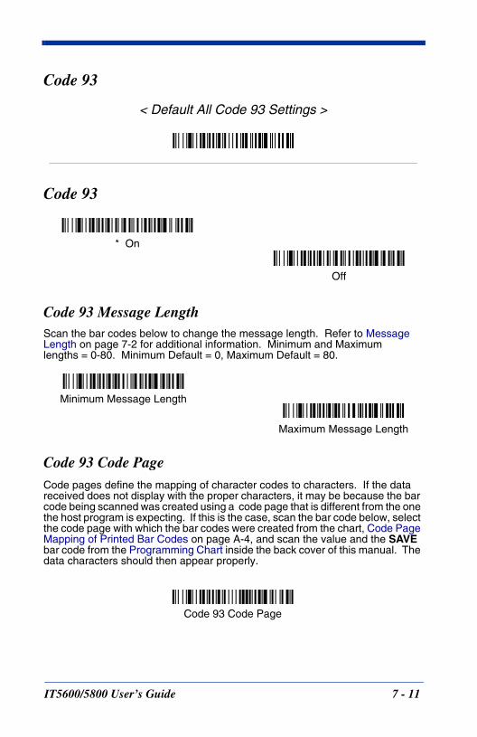
Code 93
< Default All Code 93 Settings >
Code 93
Code 93 Message LengthScan the bar codes below to change the message length. Refer to Message Length on page 7-2 for additional information. Minimum and Maximumlengths = 0-80. Minimum Default = 0, Maximum Default = 80.
Code 93 Code PageCode pages define the mapping of character codes to characters. If the data received does not display with the proper characters, it may be because the bar code being scanned was created using a code page that is different from the one the host program is expecting. If this is the case, scan the bar code below, select the code page with which the bar codes were created from the chart, Code Page Mapping of Printed Bar Codes on page A-4, and scan the value and the SAVE bar code from the Programming Chart inside the back cover of this manual. The data characters should then appear properly.
* On
Off
Minimum Message Length
Maximum Message Length
Code 93 Code Page
IT5600/5800 User’s Guide 7 - 11
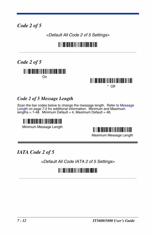
Code 2 of 5
<Default All Code 2 of 5 Settings>
Code 2 of 5
Code 2 of 5 Message LengthScan the bar codes below to change the message length. Refer to Message Length on page 7-2 for additional information. Minimum and Maximumlengths = 1-48. Minimum Default = 4, Maximum Default = 48.
IATA Code 2 of 5
<Default All Code IATA 2 of 5 Settings>
On
* Off
Minimum Message Length
Maximum Message Length
7 - 12 IT5600/5800 User’s Guide
IATA Code 2 of 5, continued
IATA Code 2 of 5 Message LengthScan the bar codes below to change the message length. Refer to Message Length on page 7-2 for additional information. Minimum and Maximumlengths = 1-48. Minimum Default = 4, Maximum Default = 48.
Matrix 2 of 5
<Default All Matrix 2 of 5 Settings>
Matrix 2 of 5
On
* Off
Minimum Message Length
Maximum Message Length
On
* Off
IT5600/5800 User’s Guide 7 - 13
Matrix 2 of 5 Message LengthScan the bar codes below to change the message length. Refer to Message Length on page 7-2 for additional information. Minimum and Maximumlengths = 1-80. Minimum Default = 4, Maximum Default = 80.
Code 11
<Default All Code 11 Settings>
Code 11
Check Digits RequiredThis option sets whether 1 or 2 check digits are required with Code 11 bar codes. Default = Two Check Digits.
Minimum Message Length
Maximum Message Length
On
* Off
One Check Digit
* Two Check Digits
7 - 14 IT5600/5800 User’s Guide
Code 11, continued
Code 11 Message LengthScan the bar codes below to change the message length. Refer to Message Length on page 7-2 for additional information. Minimum and Maximumlengths = 1-80. Minimum Default = 4, Maximum Default = 80.
Code 128
<Default All Code 128 Settings>
Code 128
Minimum Message Length
Maximum Message Length
* On
Off
IT5600/5800 User’s Guide 7 - 15
Code 128, continued
ISBT 128 ConcatenationIn 1994 the International Society of Blood Transfusion (ISBT) ratified a standard for communicating critical blood information in a uniform manner. The use of ISBT formats requires a paid license. The ISBT 128 Application Specification describes 1) the critical data elements for labeling blood products, 2) the current recommendation to use Code 128 due to its high degree of security and its space-efficient design, 3) a variation of Code 128 that supports concatenation of neighboring symbols, and 4) the standard layout for bar codes on a blood product label. Use the bar codes below to turn concatenation on or off. Default =Off.
Code 128 Message LengthScan the bar codes below to change the message length. Refer to Message Length on page 7-2 for additional information. Minimum and Maximumlengths = 0-80. Minimum Default = 0, Maximum Default = 80.
Code 128 Code PageCode pages define the mapping of character codes to characters. If the data received does not display with the proper characters, it may be because the bar code being scanned was created using a code page that is different from the one the host program is expecting. If this is the case, scan the bar code below, select the code page with which the bar codes were created from the chart, Code Page Mapping of Printed Bar Codes on page A-4, and scan the value and the SAVE bar code from the Programming Chart inside the back cover of this manual. The data characters should then appear properly.
* Off
On
Minimum Message Length
Maximum Message Length
Code 128 Code Page
7 - 16 IT5600/5800 User’s Guide
Telepen
<Default All Telepen Settings>
Telepen
Telepen OutputUsing AIM Telepen Output, the scanner reads symbols with start/stop pattern 1 and decodes them as standard full ASCII (start/stop pattern 1). When Original Telepen Output is selected, the scanner reads symbols with start/stop pattern 1 and decodes them as compressed numeric with optional full ASCII (start/stop pattern 2). Default = AIM Telepen Output.
Telepen Message LengthScan the bar codes below to change the message length. Refer to Message Length on page 7-2 for additional information. Minimum and Maximumlengths = 1-60. Minimum Default = 1, Maximum Default = 60.
On
* Off
Original Telepen Output
* AIM Telepen Output
Minimum Message Length
Maximum Message Length
IT5600/5800 User’s Guide 7 - 17
UPC A
<Default All UPC A Settings>
UPC A
UPC A Check DigitThis selection allows you to specify whether the check digit should be transmitted at the end of the scanned data or not. Default = On.
UPC A Number SystemThe numeric system digit of a U.P.C. symbol is normally transmitted at the beginning of the scanned data, but the unit can be programmed so it will not transmit it. Default = On.
* On
Off
* On
Off
Off
* On
7 - 18 IT5600/5800 User’s Guide
UPC A, continued
UPC A AddendaThis selection adds 2 or 5 digits to the end of all scanned UPC A data.Default = Off for both 2 Digit and 5 Digit Addenda.
UPC A Addenda RequiredWhen Addenda Required is set to on, the scanner will only read UPC A bar codes that have addenda. Default = Not Required.
UPC A Addenda SeparatorWhen this feature is on, there is a space between the data from the bar code and the data from the addenda. When turned off, there is no space. Default = On.
* 5 Digit Addenda Off
5 Digit Addenda On
* 2 Digit Addenda Off
2 Digit Addenda On
* Not Required
Required
Off
* On
IT5600/5800 User’s Guide 7 - 19
UPC-A/EAN-13 with Extended Coupon Code
Use the following codes to enable or disable UPC-A and EAN-13 with Extended Coupon Code. Default = On.
UPC E
<Default All UPC E Settings>
UPC E0 and UPC E1
Most U.P.C. bar codes lead with the 0 number system. For these codes, use the UPC E0 selection. If you need to read codes that lead with the 1 number system, use the UPC E1 selection. Default = On (UPC E0) and Off (UPC E1).
* On
Off
* UPC E0 On
UPC E0 Off
* UPC E1 On
UPC E1 Off
7 - 20 IT5600/5800 User’s Guide
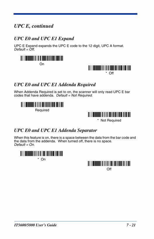
UPC E, continued
UPC E0 and UPC E1 ExpandUPC E Expand expands the UPC E code to the 12 digit, UPC A format. Default = Off.
UPC E0 and UPC E1 Addenda RequiredWhen Addenda Required is set to on, the scanner will only read UPC E bar codes that have addenda. Default = Not Required.
UPC E0 and UPC E1 Addenda SeparatorWhen this feature is on, there is a space between the data from the bar code and the data from the addenda. When turned off, there is no space. Default = On.
* Off
On
* Not Required
Required
Off
* On
IT5600/5800 User’s Guide 7 - 21
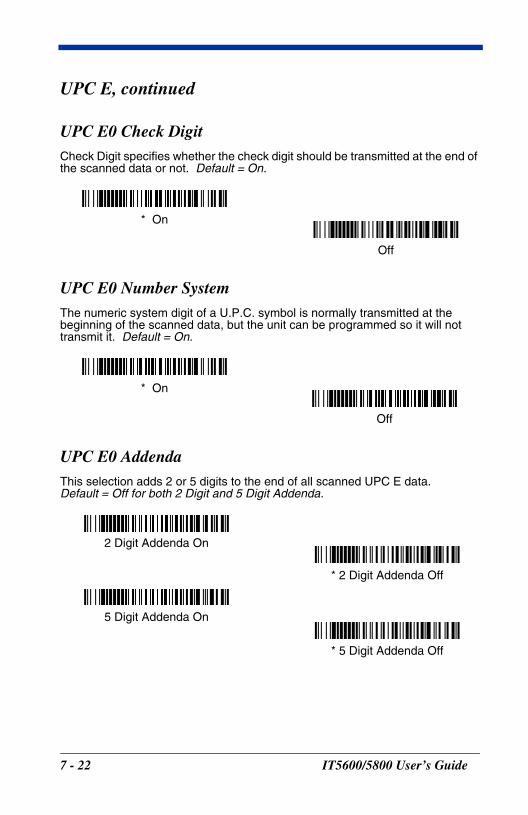
UPC E, continued
UPC E0 Check DigitCheck Digit specifies whether the check digit should be transmitted at the end of the scanned data or not. Default = On.
UPC E0 Number SystemThe numeric system digit of a U.P.C. symbol is normally transmitted at the beginning of the scanned data, but the unit can be programmed so it will not transmit it. Default = On.
UPC E0 AddendaThis selection adds 2 or 5 digits to the end of all scanned UPC E data.Default = Off for both 2 Digit and 5 Digit Addenda.
Off
* On
Off
* On
* 5 Digit Addenda Off
5 Digit Addenda On
* 2 Digit Addenda Off
2 Digit Addenda On
7 - 22 IT5600/5800 User’s Guide
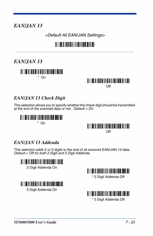
EAN/JAN 13
<Default All EAN/JAN Settings>
EAN/JAN 13
EAN/JAN 13 Check DigitThis selection allows you to specify whether the check digit should be transmitted at the end of the scanned data or not. Default = On.
EAN/JAN 13 AddendaThis selection adds 2 or 5 digits to the end of all scanned EAN/JAN 13 data.Default = Off for both 2 Digit and 5 Digit Addenda.
* On
Off
Off
* On
* 5 Digit Addenda Off
5 Digit Addenda On
* 2 Digit Addenda Off
2 Digit Addenda On
IT5600/5800 User’s Guide 7 - 23
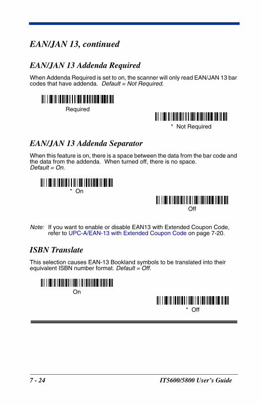
EAN/JAN 13, continued
EAN/JAN 13 Addenda RequiredWhen Addenda Required is set to on, the scanner will only read EAN/JAN 13 bar codes that have addenda. Default = Not Required.
EAN/JAN 13 Addenda SeparatorWhen this feature is on, there is a space between the data from the bar code and the data from the addenda. When turned off, there is no space. Default = On.
Note: If you want to enable or disable EAN13 with Extended Coupon Code, refer to UPC-A/EAN-13 with Extended Coupon Code on page 7-20.
ISBN TranslateThis selection causes EAN-13 Bookland symbols to be translated into their equivalent ISBN number format. Default = Off.
* Not Required
Required
Off
* On
* Off
On
7 - 24 IT5600/5800 User’s Guide
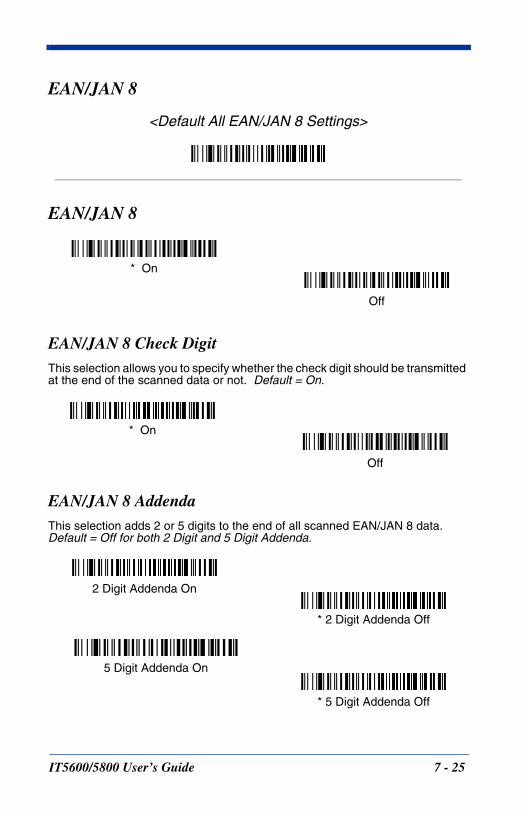
EAN/JAN 8
<Default All EAN/JAN 8 Settings>
EAN/JAN 8
EAN/JAN 8 Check DigitThis selection allows you to specify whether the check digit should be transmitted at the end of the scanned data or not. Default = On.
EAN/JAN 8 AddendaThis selection adds 2 or 5 digits to the end of all scanned EAN/JAN 8 data.Default = Off for both 2 Digit and 5 Digit Addenda.
* On
Off
Off
* On
* 5 Digit Addenda Off
5 Digit Addenda On
* 2 Digit Addenda Off
2 Digit Addenda On
IT5600/5800 User’s Guide 7 - 25

EAN/JAN 8, continued
EAN/JAN 8 Addenda RequiredWhen Addenda Required is set to on, the scanner will only read EAN/JAN 8 bar codes that have addenda. Default = Not Required.
EAN/JAN 8 Addenda SeparatorWhen this feature is on, there is a space between the data from the bar code and the data from the addenda. When turned off, there is no space. Default = On.
MSI
<Default All MSI Settings>
MSI
* Not Required
Required
Off
* On
On
* Off
7 - 26 IT5600/5800 User’s Guide
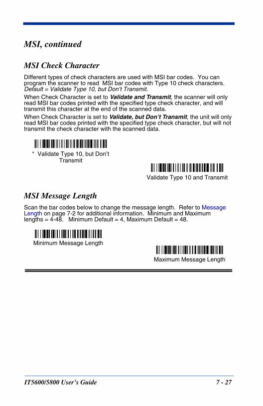
MSI, continued
MSI Check CharacterDifferent types of check characters are used with MSI bar codes. You can program the scanner to read MSI bar codes with Type 10 check characters. Default = Validate Type 10, but Don’t Transmit.When Check Character is set to Validate and Transmit, the scanner will only read MSI bar codes printed with the specified type check character, and will transmit this character at the end of the scanned data.When Check Character is set to Validate, but Don’t Transmit, the unit will only read MSI bar codes printed with the specified type check character, but will not transmit the check character with the scanned data.
MSI Message LengthScan the bar codes below to change the message length. Refer to Message Length on page 7-2 for additional information. Minimum and Maximumlengths = 4-48. Minimum Default = 4, Maximum Default = 48.
Validate Type 10 and Transmit
* Validate Type 10, but Don’t Transmit
Minimum Message Length
Maximum Message Length
IT5600/5800 User’s Guide 7 - 27
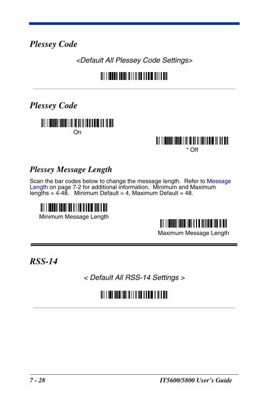
Plessey Code
<Default All Plessey Code Settings>
Plessey Code
Plessey Message LengthScan the bar codes below to change the message length. Refer to Message Length on page 7-2 for additional information. Minimum and Maximumlengths = 4-48. Minimum Default = 4, Maximum Default = 48.
RSS-14
< Default All RSS-14 Settings >
On
* Off
Minimum Message Length
Maximum Message Length
7 - 28 IT5600/5800 User’s Guide
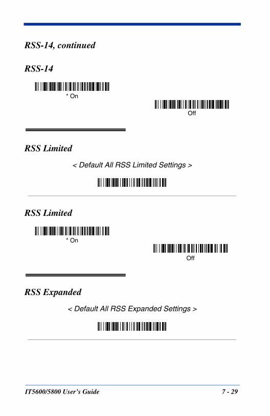
RSS-14, continued
RSS-14
RSS Limited
< Default All RSS Limited Settings >
RSS Limited
RSS Expanded
< Default All RSS Expanded Settings >
* On
Off
* On
Off
IT5600/5800 User’s Guide 7 - 29
RSS Expanded, continued
RSS Expanded
RSS Expanded Message LengthScan the bar codes below to change the message length. Refer to Message Length on page 7-2 for additional information. Minimum and Maximumlengths = 4-74. Minimum Default = 4, Maximum Default = 74.
EAN•UCC Emulation
The imager can automatically format the output from any EAN•UCC data carrier to emulate what would be encoded in an equivalent UCC/EAN-128 or RSS+Composite symbol. EAN•UCC data carriers include UPC-A and UPC-E, EAN-13 and EAN-8, ITF-14, UCC/EAN-128, and EAN•UCC RSS and Composites. If UCC/EAN-128 Emulation is selected, the AIM Symbology Identifier will be reported as “]C1”. If RSS Emulation is selected, the AIM Symbology Identifier will be reported as “]e0.” Any application that accepts EAN•UCC data can be simplified since it only needs to recognize one data carrier type. Default = EAN•UCC Emulation Off.
* On
Off
Minimum Message Length
Maximum Message Length
RSS Emulation
128 Emulation
* EAN•UCC Emulation Off
7 - 30 IT5600/5800 User’s Guide
China Post Code
<Default All China Post Code Settings>
China Post Code
China Post Message Length
Scan the bar codes below to change the message length. Refer to Message Length on page 7-2 for additional information. Minimum and Maximumlengths = 2-80. Minimum Default = 4, Maximum Default = 80.
On
* Off
Minimum Message Length
Maximum Message Length
IT5600/5800 User’s Guide 7 - 31
Korea Post Code
<Default All Korea Post Code Settings>
Korea Post Code
Korea Post Message LengthScan the bar codes below to change the message length. Refer to Message Length on page 7-2 for additional information. Minimum and Maximumlengths = 2-80. Minimum Default = 4, Maximum Default = 48.
On
* Off
Minimum Message Length
Maximum Message Length
7 - 32 IT5600/5800 User’s Guide
PosiCode
<Default All PosiCode Settings>
PosiCode A and B
You have to have PosiCode A and B on to read any of the PosiCode symbologies.
PosiCode Message LengthScan the bar codes below to change the message length. Refer to Message Length on page 7-2 for additional information. Minimum and Maximumlengths = 2-80. Minimum Default = 4, Maximum Default = 48.
* On
Off
A and B On(No Limited)
A and B and Limited A On(Limited B Off)
* A and B and Limited B On(Limited A Off)
Minimum Message Length
Maximum Message Length
IT5600/5800 User’s Guide 7 - 33
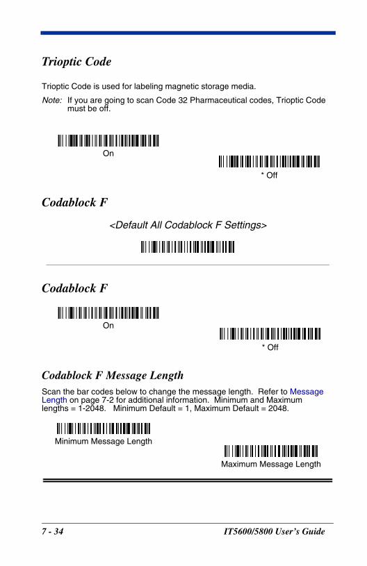
Trioptic Code
Trioptic Code is used for labeling magnetic storage media.
Note: If you are going to scan Code 32 Pharmaceutical codes, Trioptic Code must be off.
Codablock F
<Default All Codablock F Settings>
Codablock F
Codablock F Message LengthScan the bar codes below to change the message length. Refer to Message Length on page 7-2 for additional information. Minimum and Maximumlengths = 1-2048. Minimum Default = 1, Maximum Default = 2048.
On
* Off
On
* Off
Minimum Message Length
Maximum Message Length
7 - 34 IT5600/5800 User’s Guide
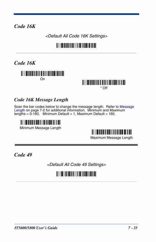
Code 16K
<Default All Code 16K Settings>
Code 16K
Code 16K Message LengthScan the bar codes below to change the message length. Refer to Message Length on page 7-2 for additional information. Minimum and Maximumlengths = 0-160. Minimum Default = 1, Maximum Default = 160.
Code 49
<Default All Code 49 Settings>
On
* Off
Minimum Message Length
Maximum Message Length
IT5600/5800 User’s Guide 7 - 35
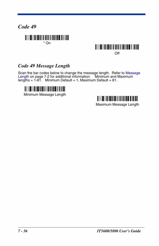
Code 49
Code 49 Message LengthScan the bar codes below to change the message length. Refer to Message Length on page 7-2 for additional information. Minimum and Maximumlengths = 1-81. Minimum Default = 1, Maximum Default = 81.
* On
Off
Minimum Message Length
Maximum Message Length
7 - 36 IT5600/5800 User’s Guide
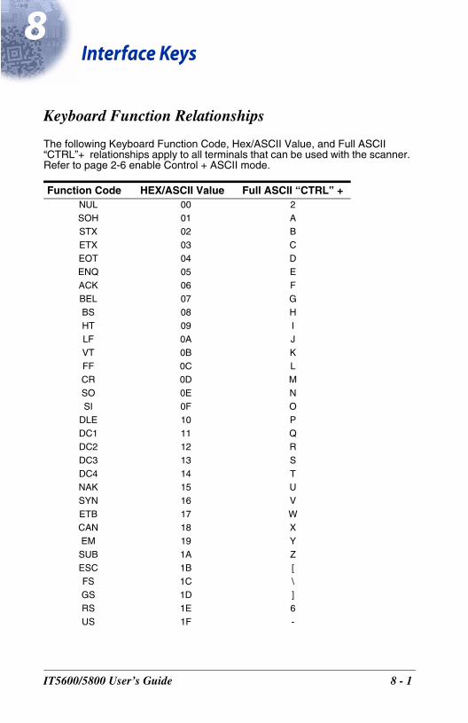
8I
IT560
nterface Keys
Keyboard Function Relationships
The following Keyboard Function Code, Hex/ASCII Value, and Full ASCII “CTRL”+ relationships apply to all terminals that can be used with the scanner. Refer to page 2-6 enable Control + ASCII mode.
Function Code HEX/ASCII Value Full ASCII “CTRL” +NUL 00 2SOH 01 ASTX 02 BETX 03 CEOT 04 DENQ 05 EACK 06 FBEL 07 GBS 08 HHT 09 ILF 0A JVT 0B KFF 0C LCR 0D MSO 0E NSI 0F O
DLE 10 PDC1 11 QDC2 12 RDC3 13 SDC4 14 TNAK 15 USYN 16 VETB 17 WCAN 18 XEM 19 YSUB 1A ZESC 1B [FS 1C \GS 1D ]RS 1E 6US 1F -
0/5800 User’s Guide 8 - 1
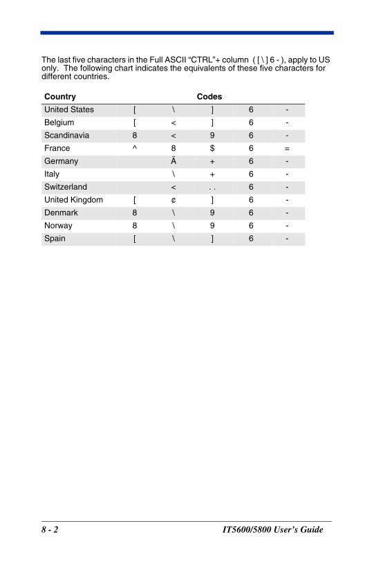
The last five characters in the Full ASCII “CTRL”+ column ( [ \ ] 6 - ), apply to US only. The following chart indicates the equivalents of these five characters for different countries.
Country Codes
United States [ \ ] 6 -
Belgium [ < ] 6 -
Scandinavia 8 < 9 6 -
France ^ 8 $ 6 =
Germany à + 6 -
Italy \ + 6 -
Switzerland < . . 6 -
United Kingdom [ ¢ ] 6 -
Denmark 8 \ 9 6 -
Norway 8 \ 9 6 -
Spain [ \ ] 6 -
8 - 2 IT5600/5800 User’s Guide
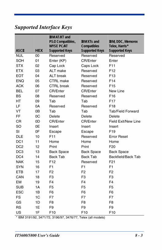
Supported Interface Keys
ASCII HEX
IBM AT/XT and PS/2 Compatibles, WYSE PC/ATSupported Keys
IBM XTs and CompatiblesSupported Keys
IBM, DDC, Memorex Telex, Harris*Supported Keys
NUL 00 Reserved Reserved ReservedSOH 01 Enter (KP) CR/Enter EnterSTX 02 Cap Lock Caps Lock F11ETX 03 ALT make Reserved F12EOT 04 ALT break Reserved F13ENQ 05 CTRL make Reserved F14ACK 06 CTRL break Reserved F15BEL 07 CR/Enter CR/Enter New LineBS 08 Reserved Reserved F16HT 09 Tab Tab F17LF 0A Reserved Reserved F18VT 0B Tab Tab Tab/Field ForwardFF 0C Delete Delete DeleteCR 0D CR/Enter CR/Enter Field Exit/New LineSO 0E Insert Insert InsertSI 0F Escape Escape F19DLE 10 F11 Reserved Error ResetDC1 11 Home Home HomeDC2 12 Print Print F20DC3 13 Back Space Back Space Back SpaceDC4 14 Back Tab Back Tab Backfield/Back TabNAK 15 F12 Reserved F21SYN 16 F1 F1 F1ETB 17 F2 F2 F2CAN 18 F3 F3 F3EM 19 F4 F4 F4SUB 1A F5 F5 F5ESC 1B F6 F6 F6FS 1C F7 F7 F7GS 1D F8 F8 F8RS 1E F9 F9 F9US 1F F10 F10 F10* IBM 3191/92, 3471/72, 3196/97, 3476/77, Telex (all models)
IT5600/5800 User’s Guide 8 - 3
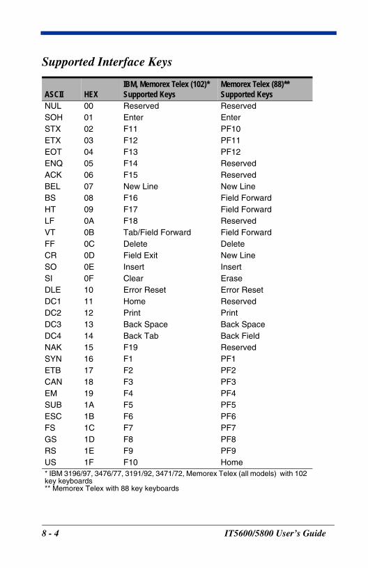
Supported Interface Keys
ASCII HEX
IBM, Memorex Telex (102)*Supported Keys
Memorex Telex (88)**Supported Keys
NUL 00 Reserved ReservedSOH 01 Enter EnterSTX 02 F11 PF10ETX 03 F12 PF11EOT 04 F13 PF12ENQ 05 F14 ReservedACK 06 F15 ReservedBEL 07 New Line New LineBS 08 F16 Field ForwardHT 09 F17 Field ForwardLF 0A F18 ReservedVT 0B Tab/Field Forward Field ForwardFF 0C Delete DeleteCR 0D Field Exit New LineSO 0E Insert InsertSI 0F Clear EraseDLE 10 Error Reset Error ResetDC1 11 Home ReservedDC2 12 Print PrintDC3 13 Back Space Back SpaceDC4 14 Back Tab Back FieldNAK 15 F19 ReservedSYN 16 F1 PF1ETB 17 F2 PF2CAN 18 F3 PF3EM 19 F4 PF4SUB 1A F5 PF5ESC 1B F6 PF6FS 1C F7 PF7GS 1D F8 PF8RS 1E F9 PF9US 1F F10 Home* IBM 3196/97, 3476/77, 3191/92, 3471/72, Memorex Telex (all models) with 102key keyboards** Memorex Telex with 88 key keyboards
8 - 4 IT5600/5800 User’s Guide
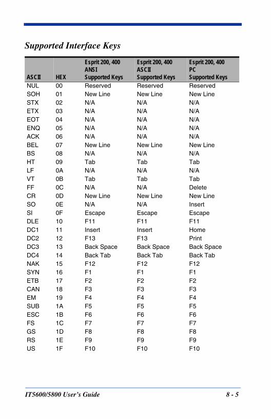
Supported Interface Keys
ASCII HEX
Esprit 200, 400ANSISupported Keys
Esprit 200, 400ASCIISupported Keys
Esprit 200, 400PCSupported Keys
NUL 00 Reserved Reserved ReservedSOH 01 New Line New Line New LineSTX 02 N/A N/A N/AETX 03 N/A N/A N/AEOT 04 N/A N/A N/AENQ 05 N/A N/A N/AACK 06 N/A N/A N/ABEL 07 New Line New Line New LineBS 08 N/A N/A N/AHT 09 Tab Tab TabLF 0A N/A N/A N/AVT 0B Tab Tab TabFF 0C N/A N/A DeleteCR 0D New Line New Line New LineSO 0E N/A N/A InsertSI 0F Escape Escape EscapeDLE 10 F11 F11 F11DC1 11 Insert Insert HomeDC2 12 F13 F13 PrintDC3 13 Back Space Back Space Back SpaceDC4 14 Back Tab Back Tab Back TabNAK 15 F12 F12 F12SYN 16 F1 F1 F1ETB 17 F2 F2 F2CAN 18 F3 F3 F3EM 19 F4 F4 F4SUB 1A F5 F5 F5ESC 1B F6 F6 F6FS 1C F7 F7 F7GS 1D F8 F8 F8RS 1E F9 F9 F9US 1F F10 F10 F10
IT5600/5800 User’s Guide 8 - 5
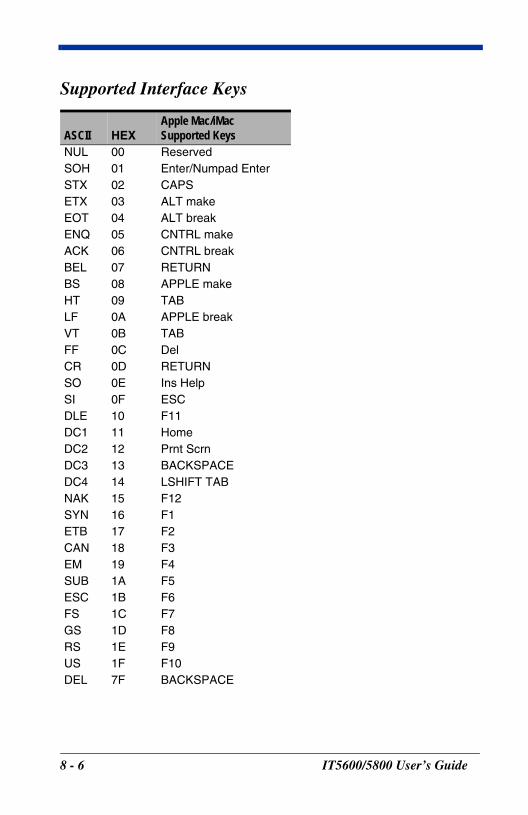
Supported Interface Keys
ASCII HEXApple Mac/iMac Supported Keys
NUL 00 ReservedSOH 01 Enter/Numpad EnterSTX 02 CAPSETX 03 ALT makeEOT 04 ALT breakENQ 05 CNTRL makeACK 06 CNTRL breakBEL 07 RETURNBS 08 APPLE makeHT 09 TABLF 0A APPLE breakVT 0B TABFF 0C DelCR 0D RETURNSO 0E Ins HelpSI 0F ESCDLE 10 F11DC1 11 HomeDC2 12 Prnt ScrnDC3 13 BACKSPACEDC4 14 LSHIFT TABNAK 15 F12SYN 16 F1ETB 17 F2CAN 18 F3EM 19 F4SUB 1A F5ESC 1B F6FS 1C F7GS 1D F8RS 1E F9US 1F F10DEL 7F BACKSPACE
8 - 6 IT5600/5800 User’s Guide
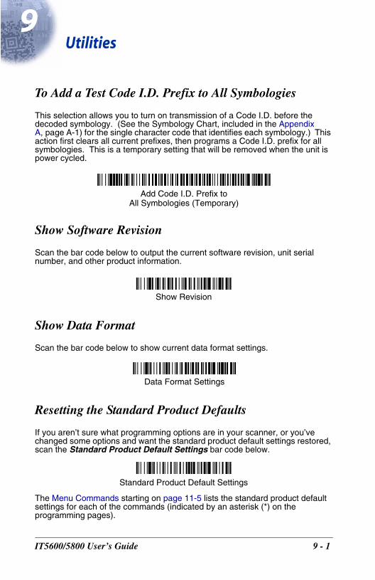
9U
IT560
tilities
To Add a Test Code I.D. Prefix to All Symbologies
This selection allows you to turn on transmission of a Code I.D. before the decoded symbology. (See the Symbology Chart, included in the Appendix A, page A-1) for the single character code that identifies each symbology.) This action first clears all current prefixes, then programs a Code I.D. prefix for all symbologies. This is a temporary setting that will be removed when the unit is power cycled.
Show Software Revision
Scan the bar code below to output the current software revision, unit serial number, and other product information.
Show Data Format
Scan the bar code below to show current data format settings.
Resetting the Standard Product Defaults
If you aren’t sure what programming options are in your scanner, or you’ve changed some options and want the standard product default settings restored, scan the Standard Product Default Settings bar code below.
The Menu Commands starting on page 11-5 lists the standard product default settings for each of the commands (indicated by an asterisk (*) on the programming pages).
Add Code I.D. Prefix toAll Symbologies (Temporary)
Show Revision
Data Format Settings
Standard Product Default Settings
0/5800 User’s Guide 9 - 1
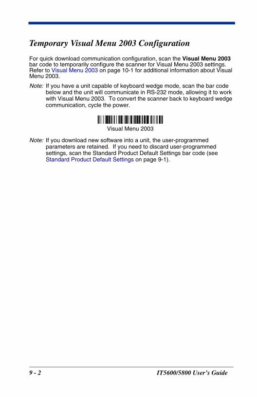
Temporary Visual Menu 2003 Configuration
For quick download communication configuration, scan the Visual Menu 2003 bar code to temporarily configure the scanner for Visual Menu 2003 settings. Refer to Visual Menu 2003 on page 10-1 for additional information about Visual Menu 2003.
Note: If you have a unit capable of keyboard wedge mode, scan the bar code below and the unit will communicate in RS-232 mode, allowing it to work with Visual Menu 2003. To convert the scanner back to keyboard wedge communication, cycle the power.
Note: If you download new software into a unit, the user-programmed parameters are retained. If you need to discard user-programmed settings, scan the Standard Product Default Settings bar code (see Standard Product Default Settings on page 9-1).
Visual Menu 2003
9 - 2 IT5600/5800 User’s Guide
10
IT560
Visual Menu 2003
Visual Menu 2003 Introduction
Visual Menu 2003 provides the ability to configure a scanning device by connecting the scanner to the com port of a PC. Visual Menu 2003 allows you to download upgrades to a scanner’s firmware, change programmed parameters, and create and print programming bar codes. Using Visual Menu 2003, you can even set up the configuration for a scanner which is not attached to your PC. This enables one expert user to establish the configuration settings for all the devices your company uses, then save these configuration files for others. A configuration file can be e-mailed or, if you prefer, an expert user can create a bar code (or series of bar codes) that contains all the customized programming parameters, and mail or fax the bar code(s) to any location. Users in other locations can scan the bar code(s) to load in the customized parameters.
To communicate with a scanner, Visual Menu 2003 requires that the PC have at least one available serial communication port and an RS-232 cable to connect the port to the device. A power supply, which plugs into the cable, is also required.
Note: If you already have a copy of Visual Menu, please note that older versions of Visual Menu will not work with the IT5600/5800. You must use Visual Menu 2003 with the IT5600/5800.
Visual Menu 2003 Operations
The Visual Menu 2003 program performs the following operations:
• Displays all configuration data, and saves the information to a file on your PC.
• Configures the device to meet your specific requirements. Visual Menu 2003 has all the programming parameters which are available via programming bar codes in this User’s Guide.
• Creates and prints a clone bar code which contains the program and configuration data from one device. This bar code can then be used to program additional devices with the same parameters.
• Selects a device from a list, then performs offline or online file configuration for that device.
Installing Visual Menu 2003 from the Web
1. Access the HHP web site at www.hhp.com.
2. Click in the Quick Search text box and enter Visual Menu 2003.
3. Click on Search Now.
0/5800 User’s Guide 10 - 1

4. Click on the entry for Visual Menu 2003.
5. When prompted, select Save File, and save the files to the c:\windows\temp directory.
6. Once you have finished downloading the file, exit the web site.
7. Using Explorer, go to the c:\windows\temp file.
8. Double click on the Visualmenu2003.exe file. Follow the screen prompts to install the Visual Menu 2003 program.
9. To start Visual Menu 2003, from the Start Menu click on Programs, Visual Menu2003, Visual Menu2003.
Note: If you wish, you can create a shortcut to the Visual Menu 2003 executable on your desktop.
10 - 2 IT5600/5800 User’s Guide
11
IT560
Serial Programming Commands
The serial programming commands can be used in place of the programming bar codes. Both the serial commands and the programming bar codes will program the IT5600/5800. For complete descriptions and examples of each serial programming command, refer to the corresponding programming bar code in this manual.
The device must be set to an RS-232 interface (see page 1-7). The following commands can be sent via a PC com port using terminal emulation software.
Conventions
The following conventions are used for menu and query command descriptions:
parameter A label representing the actual value you should send as part of a command.
[option] An optional part of a command.
{Data} Alternatives in a command.
bold Names of menus, menu commands, buttons, dialog boxes, and windows that appear on the screen.
Menu Command Syntax
Menu commands have the following syntax (spaces have been used for clarity only):
Prefix Tag SubTag {Data} [, SubTag {Data}] [; Tag SubTag {Data}] […] Storage
Prefix Three ASCII characters: SYN M CR (ASCII 22,77,13).
Tag A 3 character case-insensitive field that identifies the desired menu command group. For example, all RS-232 configuration settings are identified with a Tag of 232.
SubTag A 3 character case-insensitive field that identifies the desired menu command within the tag group. For example, the SubTag for the RS-232 baud rate is BAD.
Data The new value for a menu setting, identified by the Tag and Sub-Tag.
Storage A single character that specifies the storage table to which the command is applied. An exclamation point (!) performs the com-mand’s operation on the device’s volatile menu configuration table. A period (.) performs the command’s operation on the device’s non-volatile menu configuration table. Use the non-volatile table only for semi-permanent changes you want saved through a power cycle.
0/5800 User’s Guide 11 - 1
Query CommandsSeveral special characters can be used to query the device about its settings.
^ What is the default value for the setting(s).
? What is the device’s current value for the setting(s).
* What is the range of possible values for the setting(s). (The de-vice’s response uses a dash (-) to indicate a continuous range of values. A pipe (|) separates items in a list of non-continuous val-ues.)
Tag Field Usage
When a query is used in place of a Tag field, the query applies to the entire set of commands available for the particular storage table indicated by the Storage field of the command. In this case, the SubTag and Data fields should not be used because they are ignored by the device.
SubTag Field Usage
When a query is used in place of a SubTag field, the query applies only to the subset of commands available that match the Tag field. In this case, the Data field should not be used because it is ignored by the device.
Data Field Usage
When a query is used in place of the Data field, the query applies only to the specific command identified by the Tag and SubTag fields.
Concatenation of Multiple CommandsMultiple commands can be issued within one Prefix/Storage sequence. Only the Tag, SubTag, and Data fields must be repeated for each command in the sequence. If additional commands are to be applied to the same Tag, then the new command sequence is separated with a comma (,) and only the SubTag and Data fields of the additional command are issued. If the additional command requires a different Tag field, the command is separated from previous commands by a semicolon (;).
ResponsesThe device responds to serial commands with one of three responses:
ACK Indicates a good command which has been processed.
ENQ Indicates an invalid Tag or SubTag command.
NAK Indicates the command was good, but the Data field entry was out of the allowable range for this Tag and SubTag combination, e.g., an entry for a minimum message length of 100 when the field will only accept 2 characters.
11 - 2 IT5600/5800 User’s Guide
When responding, the device echoes back the command sequence with the status character inserted directly before each of the punctuation marks (the period, exclamation point, comma, or semicolon) in the command.
Examples of Query CommandsIn the following examples, a bracketed notation [ ] depicts a non-displayable response.
Example #1:What is the range of possible values for Codabar Coding Enable?Enter: cbrena*.Response: CBRENA0-1[ACK]
This response indicates that Codabar Coding Enable (CBRENA) has a range of values from 0 to 1 (off and on).
Example #2: What is the default value for Codabar Coding Enable?Enter: cbrena^.Response: CBRENA1[ACK]
This response indicates that the default setting for Codabar Coding Enable (CBRENA) is 1, or on.
Example #3: What is the device’s current setting for Codabar Coding Enable?Enter: cbrena?.Response: CBRENA1[ACK]
This response indicates that the device’s Codabar Coding Enable (CBRENA) is set to 1, or on.
Example #4: What are the device’s settings for all Codabar selections?Enter: cbr?.Response: CBRENA1[ACK],
SSX0[ACK],CK20[ACK],CCT1[ACK],MIN2[ACK],MAX60[ACK],DFT[ACK].
This response indicates that the device’s Codabar Coding Enable (CBRENA) is set to 1, or on; the Start/Stop Character (SSX) is set to 0, or Don’t Transmit; the Check Character (CK2) is set to 0, or Not Required;concatenation (CCT) is set to 1, or Enabled; the Minimum Message Length (MIN) is set to 2 characters; the Maximum Message Length (MAX) is set to 60 characters; and the Default setting (DFT) has no value.
IT5600/5800 User’s Guide 11 - 3

Trigger Commands
You can activate and deactivate the scanner with serial trigger commands. First, the scanner must be put in Manual/Serial Trigger Mode either by scanning the Manual/Serial Trigger Mode bar code (page 3-3), or by sending the Manual/Serial Menu Command (page 11-8). Once the scanner is in serial trigger mode, the trigger is activated and deactivated by sending the following commands:
Activate:SYN T CR
Deactivate:SYN U CR
The scanner scans until a bar code has been read, until the deactivate com-mand is sent, or until the serial time-out has been reached (see Read Time-Out on page 3-4 for a description, and the serial command on page 11-8).
Resetting the Standard Product Defaults
If you aren’t sure what programming options are in your scanner, or you’ve changed some options and want the factory settings restored, scan the Standard Product Default Settings bar code below.
The chart on the following pages lists the factory default settings for each of the menu commands (indicated by an asterisk (*) on the programming pages).
Standard Product Default Settings
11 - 4 IT5600/5800 User’s Guide
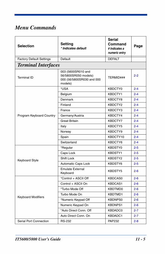
Menu Commands
Selection Setting* Indicates default
Serial Command# Indicates a numeric entry
Page
Factory Default Settings Default DEFALT
Terminal Interfaces
Terminal ID
003 (5600SR010 and56/5800SR050 models)000 (56/5800SR030 and 000 models)
TERMID###2-2
Program Keyboard Country
*USA KBDCTY0 2-4
Belgium KBDCTY1 2-4
Denmark KBDCTY8 2-4
Finland KBDCTY2 2-4
France KBDCTY3 2-4
Germany/Austria KBDCTY4 2-4
Great Britain KBDCTY7 2-4
Italy KBDCTY5 2-4
Norway KBDCTY9 2-4
Spain KBDCTY10 2-4
Switzerland KBDCTY6 2-4
Keyboard Style
*Regular KBDSTY0 2-5
Caps Lock KBDSTY1 2-5
Shift Lock KBDSTY2 2-5
Automatic Caps Lock KBDSTY6 2-5
Emulate ExternalKeyboard
KBDSTY5 2-6
Keyboard Modifiers
*Control + ASCII Off KBDCAS0 2-6
Control + ASCII On KBDCAS1 2-6
*Turbo Mode Off KBDTMD0 2-6
Turbo Mode On KBDTMD1 2-6
*Numeric Keypad Off KBDNPS0 2-6
Numeric Keypad On KBDNPS1 2-6
*Auto Direct Conn. Off KBDADC0 2-7
Auto Direct Conn. On KBDADC1 2-7
Serial Port Connection RS-232 PAP232 2-8
IT5600/5800 User’s Guide 11 - 5
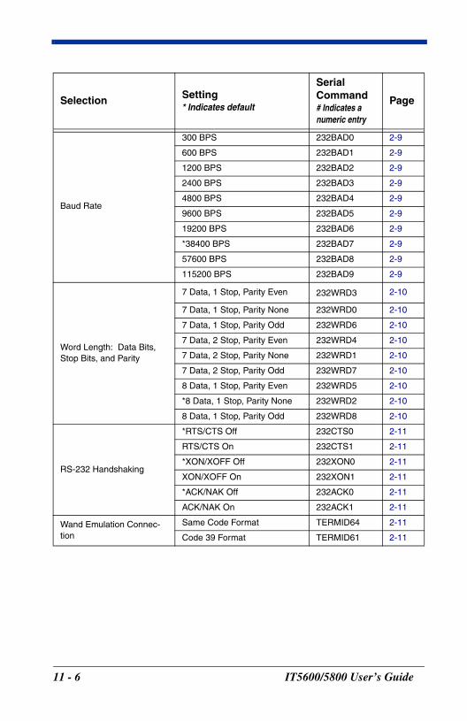
Baud Rate
300 BPS 232BAD0 2-9
600 BPS 232BAD1 2-9
1200 BPS 232BAD2 2-9
2400 BPS 232BAD3 2-9
4800 BPS 232BAD4 2-9
9600 BPS 232BAD5 2-9
19200 BPS 232BAD6 2-9
*38400 BPS 232BAD7 2-9
57600 BPS 232BAD8 2-9
115200 BPS 232BAD9 2-9
Word Length: Data Bits, Stop Bits, and Parity
7 Data, 1 Stop, Parity Even 232WRD3 2-10
7 Data, 1 Stop, Parity None 232WRD0 2-10
7 Data, 1 Stop, Parity Odd 232WRD6 2-10
7 Data, 2 Stop, Parity Even 232WRD4 2-10
7 Data, 2 Stop, Parity None 232WRD1 2-10
7 Data, 2 Stop, Parity Odd 232WRD7 2-10
8 Data, 1 Stop, Parity Even 232WRD5 2-10
*8 Data, 1 Stop, Parity None 232WRD2 2-10
8 Data, 1 Stop, Parity Odd 232WRD8 2-10
RS-232 Handshaking
*RTS/CTS Off 232CTS0 2-11
RTS/CTS On 232CTS1 2-11
*XON/XOFF Off 232XON0 2-11
XON/XOFF On 232XON1 2-11
*ACK/NAK Off 232ACK0 2-11
ACK/NAK On 232ACK1 2-11
Wand Emulation Connec-tion
Same Code Format TERMID64 2-11
Code 39 Format TERMID61 2-11
Selection Setting* Indicates default
Serial Command# Indicates a numeric entry
Page
11 - 6 IT5600/5800 User’s Guide
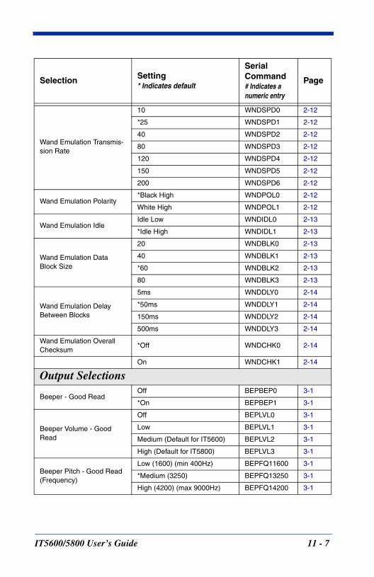
Wand Emulation Transmis-sion Rate
10 WNDSPD0 2-12
*25 WNDSPD1 2-12
40 WNDSPD2 2-12
80 WNDSPD3 2-12
120 WNDSPD4 2-12
150 WNDSPD5 2-12
200 WNDSPD6 2-12
Wand Emulation Polarity*Black High WNDPOL0 2-12
White High WNDPOL1 2-12
Wand Emulation IdleIdle Low WNDIDL0 2-13
*Idle High WNDIDL1 2-13
Wand Emulation Data Block Size
20 WNDBLK0 2-13
40 WNDBLK1 2-13
*60 WNDBLK2 2-13
80 WNDBLK3 2-13
Wand Emulation Delay Between Blocks
5ms WNDDLY0 2-14
*50ms WNDDLY1 2-14
150ms WNDDLY2 2-14
500ms WNDDLY3 2-14
Wand Emulation Overall Checksum
*Off WNDCHK0 2-14
On WNDCHK1 2-14
Output Selections
Beeper - Good Read Off BEPBEP0 3-1
*On BEPBEP1 3-1
Beeper Volume - Good Read
Off BEPLVL0 3-1
Low BEPLVL1 3-1
Medium (Default for IT5600) BEPLVL2 3-1
High (Default for IT5800) BEPLVL3 3-1
Beeper Pitch - Good Read (Frequency)
Low (1600) (min 400Hz) BEPFQ11600 3-1
*Medium (3250) BEPFQ13250 3-1
High (4200) (max 9000Hz) BEPFQ14200 3-1
Selection Setting* Indicates default
Serial Command# Indicates a numeric entry
Page
IT5600/5800 User’s Guide 11 - 7
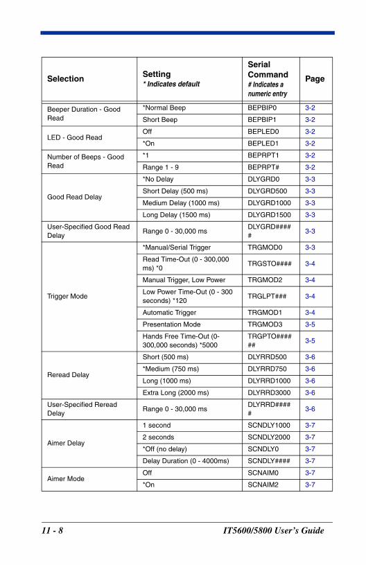
Beeper Duration - Good Read
*Normal Beep BEPBIP0 3-2
Short Beep BEPBIP1 3-2
LED - Good Read Off BEPLED0 3-2
*On BEPLED1 3-2
Number of Beeps - Good Read
*1 BEPRPT1 3-2
Range 1 - 9 BEPRPT# 3-2
Good Read Delay
*No Delay DLYGRD0 3-3
Short Delay (500 ms) DLYGRD500 3-3
Medium Delay (1000 ms) DLYGRD1000 3-3
Long Delay (1500 ms) DLYGRD1500 3-3
User-Specified Good Read Delay
Range 0 - 30,000 msDLYGRD#####
3-3
Trigger Mode
*Manual/Serial Trigger TRGMOD0 3-3
Read Time-Out (0 - 300,000 ms) *0
TRGSTO#### 3-4
Manual Trigger, Low Power TRGMOD2 3-4
Low Power Time-Out (0 - 300 seconds) *120
TRGLPT### 3-4
Automatic Trigger TRGMOD1 3-4
Presentation Mode TRGMOD3 3-5
Hands Free Time-Out (0-300,000 seconds) *5000
TRGPTO######
3-5
Reread Delay
Short (500 ms) DLYRRD500 3-6
*Medium (750 ms) DLYRRD750 3-6
Long (1000 ms) DLYRRD1000 3-6
Extra Long (2000 ms) DLYRRD3000 3-6
User-Specified Reread Delay
Range 0 - 30,000 msDLYRRD#####
3-6
Aimer Delay
1 second SCNDLY1000 3-7
2 seconds SCNDLY2000 3-7
*Off (no delay) SCNDLY0 3-7
Delay Duration (0 - 4000ms) SCNDLY#### 3-7
Aimer ModeOff SCNAIM0 3-7
*On SCNAIM2 3-7
Selection Setting* Indicates default
Serial Command# Indicates a numeric entry
Page
11 - 8 IT5600/5800 User’s Guide
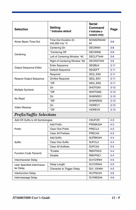
Aimer Beam Time-OutTime-Out Duration (0 - 240,000 ms) *0
SCNADR######
3-8
Centering
Centering On DECWIN1 3-8
*Centering Off DECWIN0 3-8
Left of Centering Window *40 DECLFT### 3-8
Right of Centering Window *60 DECRGT### 3-8
Output Sequence EditorEnter Sequence SEQBLK 3-11
Default Sequence SEQDFT 3-11
Require Output Sequence
Required SEQ_EN2 3-11
On/Not Required SEQ_EN1 3-11
*Off SEQ_EN0 3-11
Multiple SymbolsOn SHOTGN1 3-13
*Off SHOTGN0 3-13
No ReadOn SHWNRD1 3-13
*Off SHWNRD0 3-13
Video ReverseOn VIDREV1 3-13
*Off VIDREV0 3-13
Prefix/Suffix SelectionsAdd CR Suffix to All Symbologies VSUFCR 4-3
Prefix
Add Prefix PREBK2## 4-3
Clear One Prefix PRECL2 4-3
Clear All Prefixes PRECA2 4-3
Suffix
Add Suffix SUFBK2## 4-4
Clear One Suffix SUFCL2 4-4
Clear All Suffixes SUFCA2 4-4
Function Code Transmit*Enable RMVFNC0 4-4
Disable RMVFNC1 4-4
Intercharacter Delay DLYCHR## 4-5
User Specified Intercharac-ter Delay
Delay Length DLYCRX## 4-5
Character to Trigger Delay DLY_XX### 4-5
Interfunction Delay DLYFNC## 4-6
Intermessage Delay DLYMSG## 4-6
Selection Setting* Indicates default
Serial Command# Indicates a numeric entry
Page
IT5600/5800 User’s Guide 11 - 9
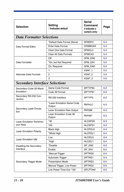
Data Formatter Selections
Data Format Editor
*Default Data Format (None) DFMDF3 5-4
Enter Data Format DFMBK3## 5-4
Clear One Data Format DFMCL3 5-4
Clear All Data Formats DFMCA3 5-4
Data Formatter
Off DFM_EN0 5-5
*On, but Not Required DFM_EN1 5-5
On, Required DFM_EN2 5-5
Alternate Data Formats
1 VSAF_1 5-5
2 VSAF_2 5-5
3 VSAF_3 5-5
Secondary Interface SelectionsSecondary Code 39 Wand Emulation
Same Code Format 2IFTYP64 6-2
Code 39 Format 2IFTYP61 6-2
Secondary RS-232 Con-nection
RS-232 Interface 2IFTYP0 6-2
Secondary Laser Emula-tion
*Laser Emulation Same Code Output
PAPHLC 6-3
Laser Emulation Raw Output PAP088 6-3
Laser Emulation Code 39 Output
PAP087 6-3
Laser Emulation Transmis-sion Rate
*36 HLCSPD0 6-3
100 HLCSPD1 6-3
Laser Emulation PolarityBlack High HLCPOL0 6-4
*White High HLCPOL1 6-4
Laser Emulation IdleLow HLCIDL0 6-4
*High HLCIDL1 6-4
Disabling the Secondary Interface
*Disable 2IF_EN0 6-2
Enable 2IF_EN1 6-2
Secondary Trigger Mode
*Manual Trigger 2IFTRG0 6-4
Automatic Trigger 2IFTRG1 6-4
Presentation Mode 2IFTRG3 6-4
Manual Trigger, Low Power 2IFTRG2 6-5
Low Power Time-Out *120 2IFLPT### 6-5
Selection Setting* Indicates default
Serial Command# Indicates a numeric entry
Page
11 - 10 IT5600/5800 User’s Guide
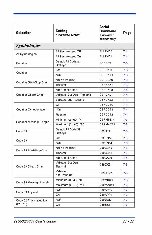
Symbologies
All SymbologiesAll Symbologies Off ALLENA0 7-1
All Symbologies On ALLENA1 7-1
CodabarDefault All Codabar Settings
CBRDFT 7-3
CodabarOff CBRENA0 7-3
*On CBRENA1 7-3
Codabar Start/Stop Char.*Don’t Transmit CBRSSX0 7-3
Transmit CBRSSX1 7-3
Codabar Check Char.
*No Check Char. CBRCK20 7-4
Validate, But Don’t Transmit CBRCK21 7-4
Validate, and Transmit CBRCK22 7-4
Codabar Concatenation
Off CBRCCT0 7-4
*On CBRCCT1 7-4
Require CBRCCT2 7-4
Codabar Message LengthMinimum (2 - 60) *4 CBRMIN## 7-5
Maximum (2 - 60) *60 CBRMAX## 7-5
Code 39Default All Code 39 Settings
C39DFT 7-5
Code 39Off C39ENA0 7-5
*On C39ENA1 7-5
Code 39 Start/Stop Char.*Don’t Transmit C39SSX0 7-5
Transmit C39SSX1 7-5
Code 39 Check Char.
*No Check Char. C39CK20 7-6
Validate, But Don’t Transmit
C39CK21 7-6
Validate, and Transmit
C39CK22 7-6
Code 39 Message LengthMinimum (0 - 48) *0 C39MIN## 7-6
Maximum (0 - 48) *48 C39MAX## 7-6
Code 39 Append*Off C39APP0 7-7
On C39APP1 7-7
Code 32 Pharmaceutical (PARAF)
*Off C39B320 7-7
On C39B321 7-7
Selection Setting* Indicates default
Serial Command# Indicates a numeric entry
Page
IT5600/5800 User’s Guide 11 - 11
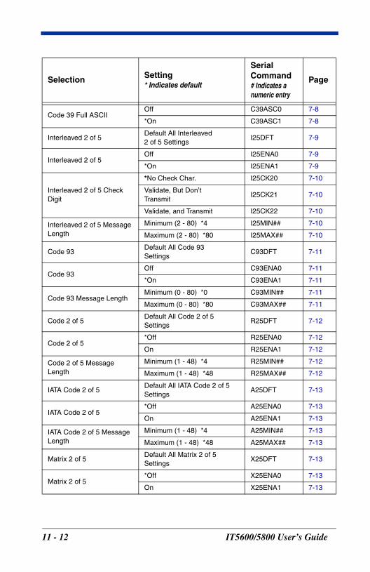
Code 39 Full ASCIIOff C39ASC0 7-8
*On C39ASC1 7-8
Interleaved 2 of 5Default All Interleaved2 of 5 Settings
I25DFT 7-9
Interleaved 2 of 5Off I25ENA0 7-9
*On I25ENA1 7-9
Interleaved 2 of 5 Check Digit
*No Check Char. I25CK20 7-10
Validate, But Don’t Transmit
I25CK21 7-10
Validate, and Transmit I25CK22 7-10
Interleaved 2 of 5 Message Length
Minimum (2 - 80) *4 I25MIN## 7-10
Maximum (2 - 80) *80 I25MAX## 7-10
Code 93Default All Code 93 Settings
C93DFT 7-11
Code 93Off C93ENA0 7-11
*On C93ENA1 7-11
Code 93 Message LengthMinimum (0 - 80) *0 C93MIN## 7-11
Maximum (0 - 80) *80 C93MAX## 7-11
Code 2 of 5Default All Code 2 of 5Settings
R25DFT 7-12
Code 2 of 5*Off R25ENA0 7-12
On R25ENA1 7-12
Code 2 of 5 Message Length
Minimum (1 - 48) *4 R25MIN## 7-12
Maximum (1 - 48) *48 R25MAX## 7-12
IATA Code 2 of 5Default All IATA Code 2 of 5Settings
A25DFT 7-13
IATA Code 2 of 5*Off A25ENA0 7-13
On A25ENA1 7-13
IATA Code 2 of 5 Message Length
Minimum (1 - 48) *4 A25MIN## 7-13
Maximum (1 - 48) *48 A25MAX## 7-13
Matrix 2 of 5Default All Matrix 2 of 5Settings
X25DFT 7-13
Matrix 2 of 5*Off X25ENA0 7-13
On X25ENA1 7-13
Selection Setting* Indicates default
Serial Command# Indicates a numeric entry
Page
11 - 12 IT5600/5800 User’s Guide
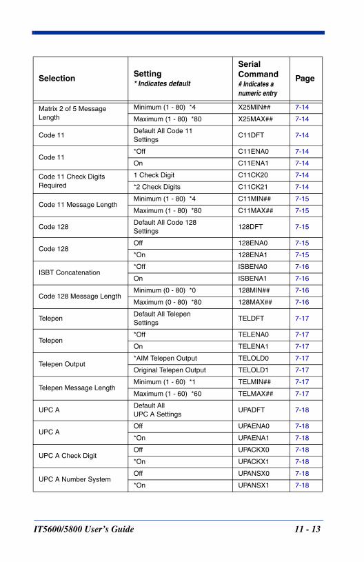
Matrix 2 of 5 Message Length
Minimum (1 - 80) *4 X25MIN## 7-14
Maximum (1 - 80) *80 X25MAX## 7-14
Code 11Default All Code 11 Settings
C11DFT 7-14
Code 11*Off C11ENA0 7-14
On C11ENA1 7-14
Code 11 Check Digits Required
1 Check Digit C11CK20 7-14
*2 Check Digits C11CK21 7-14
Code 11 Message LengthMinimum (1 - 80) *4 C11MIN## 7-15
Maximum (1 - 80) *80 C11MAX## 7-15
Code 128Default All Code 128Settings
128DFT 7-15
Code 128Off 128ENA0 7-15
*On 128ENA1 7-15
ISBT Concatenation*Off ISBENA0 7-16
On ISBENA1 7-16
Code 128 Message LengthMinimum (0 - 80) *0 128MIN## 7-16
Maximum (0 - 80) *80 128MAX## 7-16
TelepenDefault All TelepenSettings
TELDFT 7-17
Telepen*Off TELENA0 7-17
On TELENA1 7-17
Telepen Output*AIM Telepen Output TELOLD0 7-17
Original Telepen Output TELOLD1 7-17
Telepen Message LengthMinimum (1 - 60) *1 TELMIN## 7-17
Maximum (1 - 60) *60 TELMAX## 7-17
UPC ADefault All UPC A Settings
UPADFT 7-18
UPC AOff UPAENA0 7-18
*On UPAENA1 7-18
UPC A Check DigitOff UPACKX0 7-18
*On UPACKX1 7-18
UPC A Number SystemOff UPANSX0 7-18
*On UPANSX1 7-18
Selection Setting* Indicates default
Serial Command# Indicates a numeric entry
Page
IT5600/5800 User’s Guide 11 - 13
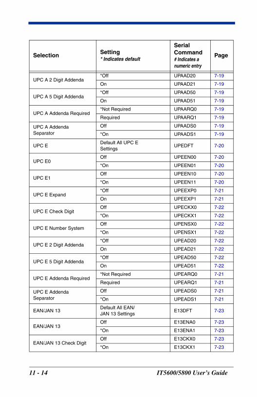
UPC A 2 Digit Addenda*Off UPAAD20 7-19
On UPAAD21 7-19
UPC A 5 Digit Addenda*Off UPAAD50 7-19
On UPAAD51 7-19
UPC A Addenda Required*Not Required UPAARQ0 7-19
Required UPAARQ1 7-19
UPC A Addenda Separator
Off UPAADS0 7-19
*On UPAADS1 7-19
UPC EDefault All UPC ESettings
UPEDFT 7-20
UPC E0Off UPEEN00 7-20
*On UPEEN01 7-20
UPC E1Off UPEEN10 7-20
*On UPEEN11 7-20
UPC E Expand*Off UPEEXP0 7-21
On UPEEXP1 7-21
UPC E Check DigitOff UPECKX0 7-22
*On UPECKX1 7-22
UPC E Number SystemOff UPENSX0 7-22
*On UPENSX1 7-22
UPC E 2 Digit Addenda*Off UPEAD20 7-22
On UPEAD21 7-22
UPC E 5 Digit Addenda*Off UPEAD50 7-22
On UPEAD51 7-22
UPC E Addenda Required*Not Required UPEARQ0 7-21
Required UPEARQ1 7-21
UPC E Addenda Separator
Off UPEADS0 7-21
*On UPEADS1 7-21
EAN/JAN 13Default All EAN/JAN 13 Settings
E13DFT 7-23
EAN/JAN 13Off E13ENA0 7-23
*On E13ENA1 7-23
EAN/JAN 13 Check DigitOff E13CKX0 7-23
*On E13CKX1 7-23
Selection Setting* Indicates default
Serial Command# Indicates a numeric entry
Page
11 - 14 IT5600/5800 User’s Guide
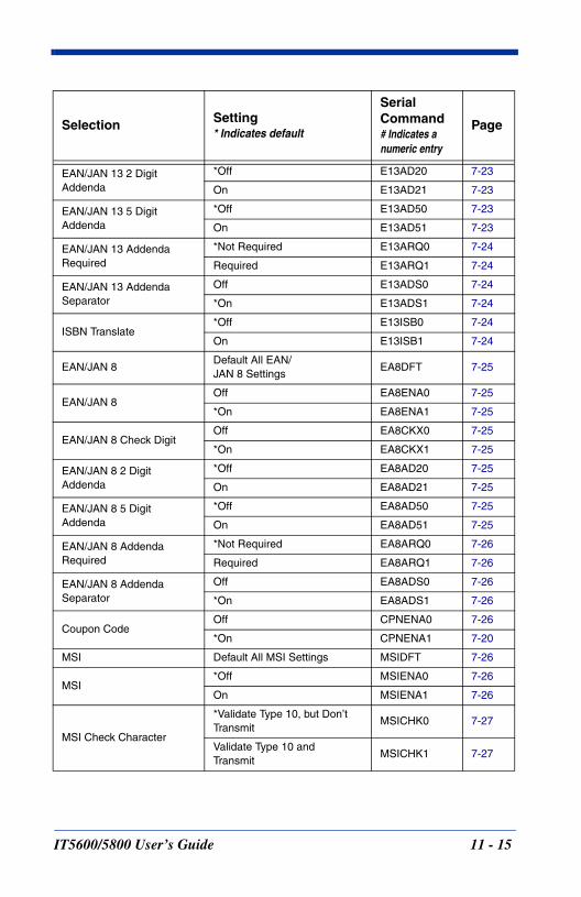
EAN/JAN 13 2 Digit Addenda
*Off E13AD20 7-23
On E13AD21 7-23
EAN/JAN 13 5 Digit Addenda
*Off E13AD50 7-23
On E13AD51 7-23
EAN/JAN 13 Addenda Required
*Not Required E13ARQ0 7-24
Required E13ARQ1 7-24
EAN/JAN 13 Addenda Separator
Off E13ADS0 7-24
*On E13ADS1 7-24
ISBN Translate*Off E13ISB0 7-24
On E13ISB1 7-24
EAN/JAN 8Default All EAN/JAN 8 Settings
EA8DFT 7-25
EAN/JAN 8Off EA8ENA0 7-25
*On EA8ENA1 7-25
EAN/JAN 8 Check DigitOff EA8CKX0 7-25
*On EA8CKX1 7-25
EAN/JAN 8 2 Digit Addenda
*Off EA8AD20 7-25
On EA8AD21 7-25
EAN/JAN 8 5 Digit Addenda
*Off EA8AD50 7-25
On EA8AD51 7-25
EAN/JAN 8 Addenda Required
*Not Required EA8ARQ0 7-26
Required EA8ARQ1 7-26
EAN/JAN 8 Addenda Separator
Off EA8ADS0 7-26
*On EA8ADS1 7-26
Coupon CodeOff CPNENA0 7-26
*On CPNENA1 7-20
MSI Default All MSI Settings MSIDFT 7-26
MSI*Off MSIENA0 7-26
On MSIENA1 7-26
MSI Check Character
*Validate Type 10, but Don’t Transmit
MSICHK0 7-27
Validate Type 10 and Transmit
MSICHK1 7-27
Selection Setting* Indicates default
Serial Command# Indicates a numeric entry
Page
IT5600/5800 User’s Guide 11 - 15
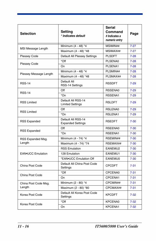
MSI Message LengthMinimum (4 - 48) *4 MSIMIN## 7-27
Maximum (4 - 48) *48 MSIMAX## 7-27
Plessey Code Default All Plessey Settings PLSDFT 7-28
Plessey Code*Off PLSENA0 7-28
On PLSENA1 7-28
Plessey Message LengthMinimum (4 - 48) *4 PLSMIN## 7-28
Maximum (4 - 48) *48 PLSMAX## 7-28
RSS-14Default All RSS-14 Settings
RSSDFT 7-29
RSS-14Off RSSENA0 7-29
*On RSSENA1 7-29
RSS LimitedDefault All RSS-14Limited Settings
RSLDFT 7-29
RSS LimitedOff RSLENA0 7-29
*On RSLENA1 7-29
RSS ExpandedDefault All RSS-14Expanded Settings
RSEDFT 7-30
RSS ExpandedOff RSEENA0 7-30
*On RSEENA1 7-30
RSS Expanded Msg. Length
Minimum (4 - 74) *4 RSEMIN## 7-30
Maximum (4 - 74) *74 RSEMAX## 7-30
EAN•UCC Emulation
RSS Emulation EANEMU2 7-30
128 Emulation EANEMU1 7-30
*EAN•UCC Emulation Off EANEMU0 7-30
China Post CodeDefault All China Post Code Settings
CPCDFT 7-31
China Post Code*Off CPCENA0 7-31
On CPCENA1 7-31
China Post Code Msg. Length
Minimum (2 - 80) *4 CPCMIN## 7-31
Maximum (2 - 80) *80 CPCMAX## 7-31
Korea Post CodeDefault All Korea Post Code Settings
KPCDFT 7-32
Korea Post Code*Off KPCENA0 7-32
On KPCENA1 7-32
Selection Setting* Indicates default
Serial Command# Indicates a numeric entry
Page
11 - 16 IT5600/5800 User’s Guide
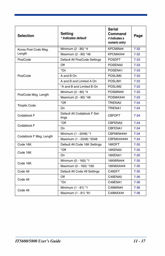
Korea Post Code Msg. Length
Minimum (2 - 80) *4 KPCMIN## 7-32
Maximum (2 - 80) *48 KPCMAX## 7-32
PosiCode Default All PosiCode Settings POSDFT 7-33
PosiCode
Off POSENA0 7-33
*On POSENA1 7-33
A and B On POSLIM0 7-33
A and B and Limited A On POSLIM1 7-33
*A and B and Limited B On POSLIM2 7-33
PosiCode Msg. LengthMinimum (2 - 80) *4 POSMIN## 7-33
Maximum (2 - 80) *48 POSMAX## 7-33
Trioptic Code*Off TRIENA0 7-34
On TRIENA1 7-34
Codablock FDefault All Codablock F Set-tings
CBFDFT 7-34
Codablock F*Off CBFENA0 7-34
On CBFENA1 7-34
Codablock F Msg. LengthMinimum (1 - 2048) *1 CBFMIN#### 7-34
Maximum (1 - 2048) *2048 CBFMAX#### 7-34
Code 16K Default All Code 16K Settings 16KDFT 7-35
Code 16K*Off 16KENA0 7-35
On 16KENA1 7-35
Code 16KMinimum (0 - 160) *1 16KMIN### 7-35
Maximum (0 - 160) *160 16KMAX### 7-35
Code 49 Default All Code 49 Settings C49DFT 7-35
Code 49Off C49ENA0 7-36
*On C49ENA1 7-36
Code 49Minimum (1 - 81) *1 C49MIN## 7-36
Maximum (1 - 81) *81 C49MAX## 7-36
Selection Setting* Indicates default
Serial Command# Indicates a numeric entry
Page
IT5600/5800 User’s Guide 11 - 17

11 - 18 IT5600/5800 User’s Guide
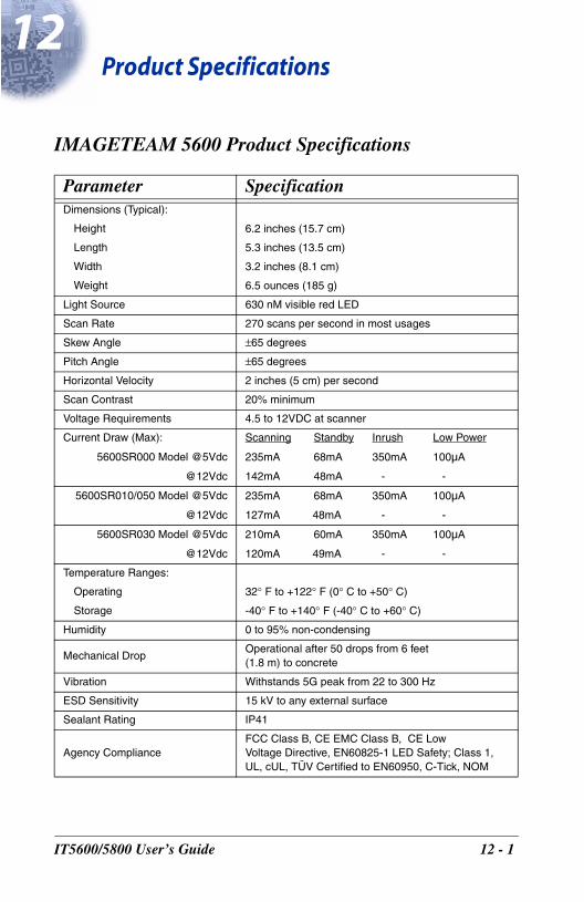
12
IT560
Product Specifications
IMAGETEAM 5600 Product Specifications
Parameter SpecificationDimensions (Typical):
Height 6.2 inches (15.7 cm)
Length 5.3 inches (13.5 cm)
Width 3.2 inches (8.1 cm)
Weight 6.5 ounces (185 g)
Light Source 630 nM visible red LED
Scan Rate 270 scans per second in most usages
Skew Angle ±65 degrees
Pitch Angle ±65 degrees
Horizontal Velocity 2 inches (5 cm) per second
Scan Contrast 20% minimum
Voltage Requirements 4.5 to 12VDC at scanner
Current Draw (Max): Scanning Standby Inrush Low Power
5600SR000 Model @5Vdc 235mA 68mA 350mA 100µA
@12Vdc 142mA 48mA - -
5600SR010/050 Model @5Vdc 235mA 68mA 350mA 100µA
@12Vdc 127mA 48mA - -
5600SR030 Model @5Vdc 210mA 60mA 350mA 100µA
@12Vdc 120mA 49mA - -
Temperature Ranges:
Operating 32° F to +122° F (0° C to +50° C)
Storage -40° F to +140° F (-40° C to +60° C)
Humidity 0 to 95% non-condensing
Mechanical DropOperational after 50 drops from 6 feet (1.8 m) to concrete
Vibration Withstands 5G peak from 22 to 300 Hz
ESD Sensitivity 15 kV to any external surface
Sealant Rating IP41
Agency ComplianceFCC Class B, CE EMC Class B, CE LowVoltage Directive, EN60825-1 LED Safety; Class 1, UL, cUL, TÜV Certified to EN60950, C-Tick, NOM
0/5800 User’s Guide 12 - 1

IMAGETEAM 5600 Depth of Field
Minimum Bar Width
Maximum Near Field
Minimum Far Field (no ambient lighting)
13 mil 100% UPC 1 in (2.5 cm) 24 in (61 cm)
7.5 mil Code 39 4 in (10 cm) 14 in (36 cm)
10 mil Code 39 2 in (5 cm) 18 in (46 cm)
13 mil Code 39 1 in (2.5 cm) 24 in (61 cm)
15 mil Code 39 1 in (2.5 cm) 28 in (71 cm)
20 mil Code 39 1 in (2.5 cm) 36 in (91 cm)
55 mil Code 39 2.5 in (7 cm) 44 in (112 cm)
12 - 2 IT5600/5800 User’s Guide
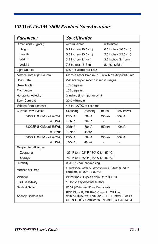
IMAGETEAM 5800 Product Specifications
Parameter SpecificationDimensions (Typical): without aimer with aimer
Height 6.4 inches (16.3 cm) 6.5 inches (16.5 cm)
Length 5.3 inches (13.5 cm) 5.3 inches (13.5 cm)
Width 3.2 inches (8.1 cm) 3.2 inches (8.1 cm)
Weight 7.5 ounces (213 g) 8.4 oz. (238 g)
Light Source 630 nm visible red LED
Aimer Beam Light Source Class 2 Laser Product, 1.0 mW Max Output:650 nm
Scan Rate 270 scans per second in most usages
Skew Angle ±65 degrees
Pitch Angle ±65 degrees
Horizontal Velocity 2 inches (5 cm) per second
Scan Contrast 20% minimum
Voltage Requirements 4.5 to 12VDC at scanner
Current Draw (Max): Scanning Standby Inrush Low Power
5800SR00X Model @5Vdc 235mA 68mA 350mA 100µA
@12Vdc 142mA 48mA - -
5800SR05X Model @5Vdc 235mA 68mA 350mA 100µA
@12Vdc 127mA 48mA - -
5800SR03X Model @5Vdc 210mA 60mA 350mA 100µA
@12Vdc 120mA 49mA - -
Temperature Ranges:
Operating -22° F to +122° F (-30° C to +50° C)
Storage -40° F to +140° F (-40° C to +60° C)
Humidity 0 to 95% non-condensing
Mechanical DropOperational after 50 drops from 6.5 feet (2 m) to concrete @ -22° F (-30° C)
Vibration Withstands 5G peak from 22 to 300 Hz
ESD Sensitivity 15 kV to any external surface
Sealant Rating IP 54 (Water and Dust Resistant)
Agency ComplianceFCC Class B, CE EMC Class B, CE LowVoltage Directive, EN60825-1 LED Safety; Class 1, UL, cUL, TÜV Certified to EN60950, C-Tick, NOM
IT5600/5800 User’s Guide 12 - 3
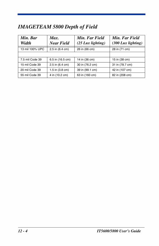
IMAGETEAM 5800 Depth of Field
Min. Bar Width
Max.Near Field
Min. Far Field(25 Lux lighting)
Min. Far Field(300 Lux lighting)
13 mil 100% UPC 2.5 in (6.4 cm) 26 in (66 cm) 28 in (71 cm)
7.5 mil Code 39 6.5 in (16.5 cm) 14 in (36 cm) 15 in (38 cm)
15 mil Code 39 2.5 in (6.4 cm) 30 in (76.2 cm) 31 in (78.7 cm)
20 mil Code 39 1.5 in (3.8 cm) 39 in (99.1 cm) 42 in (107 cm)
55 mil Code 39 4 in (10.2 cm) 63 in (160 cm) 82 in (208 cm)
12 - 4 IT5600/5800 User’s Guide
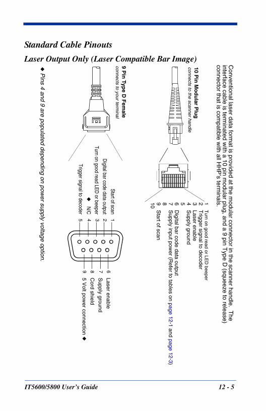
Standard Cable Pinouts
Laser Output Only (Laser Compatible Bar Image)10 P
in M
od
ular P
lug
connects to the scanner handle
1T
urn on good read or LED
beeper2
Trigger signal to decoder
3Laser enable
4S
upply ground56
Digital bar code data output
7S
upply input power (R
efer to tables on page12-1 and page
12-3)89
Start of scan
10
Start of scan
Digital bar code data output
Turn on good read LED or beeper
◆
N/C
Trigger signal to decoder
9 Pin
Type D
Fem
aleconnects to your term
inal
Laser enable
Supply ground
Cord shield
5 Volt pow
er connection ◆
12345
6789
◆ P
ins 4 and 9 are populated depending on power supply voltage option.
Conventional laser data form
at is provided at the modular connector in the scanner handle. T
he interface cable is term
inated with a 10 pin m
odular plug, and a 9 pin Type D
(squeeze to release) connector that is com
patible with all H
HP
’s terminals.
IT5600/5800 User’s Guide 12 - 5
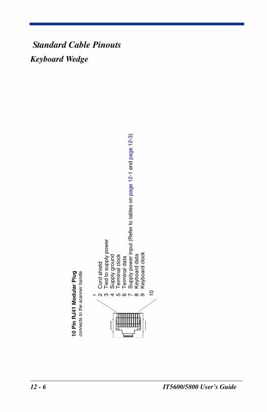
Standard Cable Pinouts
Keyboard Wedge
10 P
in R
J41
Mo
du
lar
Plu
gco
nnec
ts to
the
scan
ner
hand
le
1 2C
ord
shie
ld3
Tie
d to
sup
ply
pow
er4
Sup
ply
grou
nd5
Ter
min
al c
lock
6T
erm
inal
dat
a7
Sup
ply
pow
er in
put (
Ref
er to
tabl
es o
n pa
ge12
-1 a
nd p
age
12-3
)8
Key
boar
d da
ta9
Key
boar
d cl
ock
10
12 - 6 IT5600/5800 User’s Guide
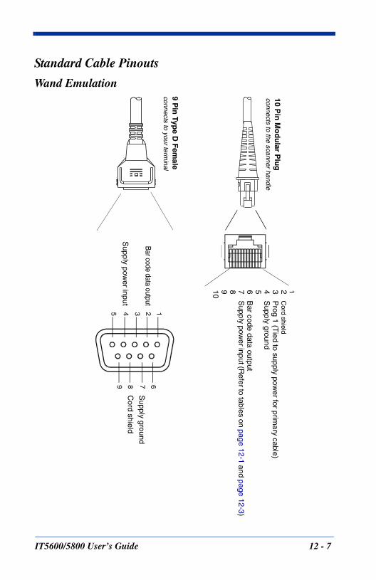
Standard Cable Pinouts
Wand Emulation10 P
in M
od
ular P
lug
connects to the scanner handle
12C
ord shield3
Prog 1 (T
ied to supply power for prim
ary cable)4
Supply ground
56B
ar code data output7
Supply pow
er input (Refer to tables on page
12-1 and page12-3)
8910
Bar code data output
Supply pow
er input
9 Pin
Type D
Fem
aleconnects to your term
inal
Supply ground
Cord shield
12345
6789
IT5600/5800 User’s Guide 12 - 7
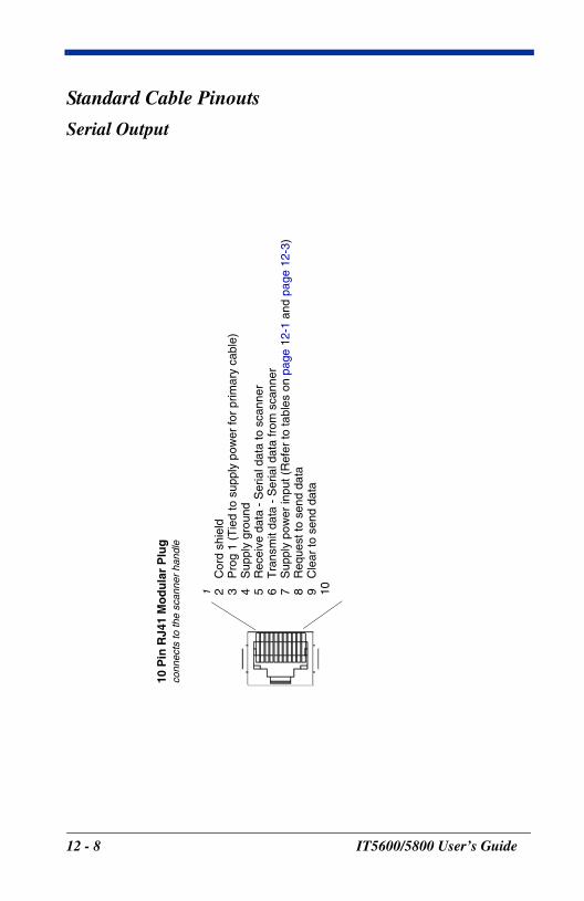
Standard Cable Pinouts
Serial Output
10 P
in R
J41
Mo
du
lar
Plu
gco
nnec
ts to
the
scan
ner
hand
le
1 2C
ord
shie
ld3
Pro
g 1
(Tie
d to
sup
ply
pow
er fo
r pr
imar
y ca
ble)
4S
uppl
y gr
ound
5R
ecei
ve d
ata
- S
eria
l dat
a to
sca
nner
6T
rans
mit
data
- S
eria
l dat
a fr
om s
cann
er7
Sup
ply
pow
er in
put (
Ref
er to
tabl
es o
n pa
ge12
-1 a
nd p
age
12-3
)8
Req
uest
to s
end
data
9C
lear
to s
end
data
10
12 - 8 IT5600/5800 User’s Guide
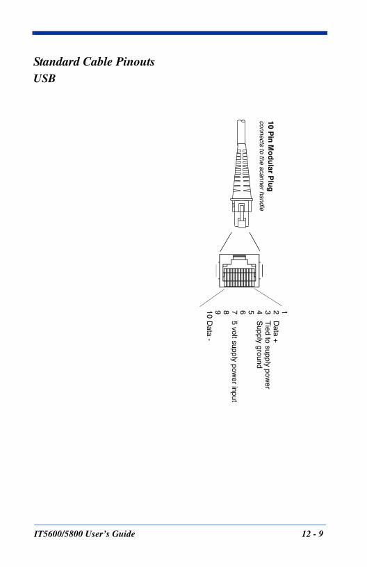
Standard Cable PinoutsUSB
10 Pin
Mo
du
lar Plu
gconnects to the scanner handle
12D
ata +3
Tied to supply pow
er4
Supply ground
5675 volt supply pow
er input8910
Data -
IT5600/5800 User’s Guide 12 - 9

12 - 10 IT5600/5800 User’s Guide
13
IT560
Maintenance
Repairs
Repairs and/or upgrades are not to be performed on this product. These services are to be performed only by an authorized service center. Please see Customer Support on page 14-1 for further information.
Maintenance
The IT5600/5800 provides reliable and efficient operation with a minimum of care. Although specific maintenance is not required, the following periodic checks ensure dependable scanner operation:
Cleaning the Scanner’s WindowReading performance may degrade if the scanner’s window is not clean. If the window is visibly dirty, or if the scanner isn’t operating well, clean the window with a soft cloth or lens tissue dampened with water (or a mild detergent- water solution or alcohol). If a detergent solution is used, rinse with a clean lens tissue dampened with water only.
The scanner’s housing may also be cleaned the same way.
Inspecting Cords and ConnectorsInspect the scanner’s interface cable and connector for wear or other signs of damage. A badly worn cable or damaged connector may interfere with scanner operation. Contact your HHP distributor for information about cable replacement. Cable replacement instructions are on page 13-2.
! Caution:Do not submerge the scanner in water. Do not use
abrasive wipes or tissues on the scanner’s window – abrasive wipes may scratch the window.
Never use solvents (e.g., acetone, benzene, ether, or phenol-based agents) on the housing or window –
solvents may damage the finish or the window.
0/5800 User’s Guide 13 - 1
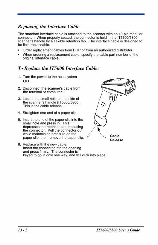
Replacing the Interface CableThe standard interface cable is attached to the scanner with an 10-pin modular connector. When properly seated, the connector is held in the IT5600/5800 scanner’s handle by a flexible retention tab. The interface cable is designed to be field replaceable.
• Order replacement cables from HHP or from an authorized distributor.• When ordering a replacement cable, specify the cable part number of the
original interface cable.
To Replace the IT5600 Interface Cable:
1. Turn the power to the host system OFF.
2. Disconnect the scanner’s cable from the terminal or computer.
3. Locate the small hole on the side of the scanner’s handle (IT5600/5800). This is the cable release.
4. Straighten one end of a paper clip.
5. Insert the end of the paper clip into the small hole and press in. This depresses the retention tab, releasing the connector. Pull the connector out while maintaining pressure on the paper clip, then remove the paper clip.
6. Replace with the new cable. Insert the connector into the opening and press firmly. The connector is keyed to go in only one way, and will click into place.
CableRelease
13 - 2 IT5600/5800 User’s Guide
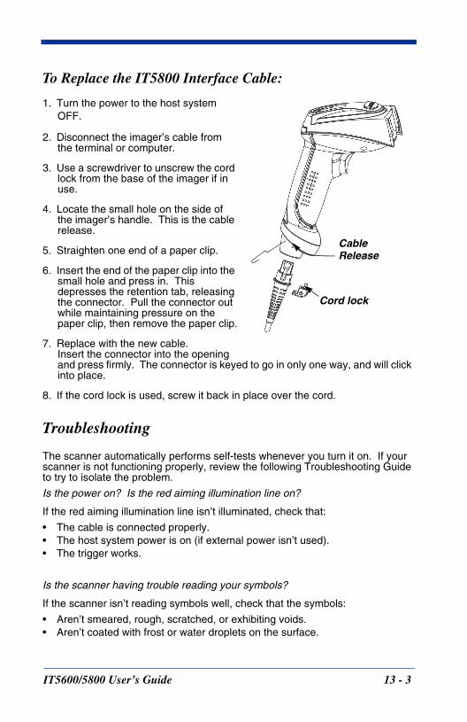
To Replace the IT5800 Interface Cable:
1. Turn the power to the host system OFF.
2. Disconnect the imager’s cable from the terminal or computer.
3. Use a screwdriver to unscrew the cord lock from the base of the imager if in use.
4. Locate the small hole on the side of the imager’s handle. This is the cable release.
5. Straighten one end of a paper clip.
6. Insert the end of the paper clip into the small hole and press in. This depresses the retention tab, releasing the connector. Pull the connector out while maintaining pressure on the paper clip, then remove the paper clip.
7. Replace with the new cable. Insert the connector into the opening and press firmly. The connector is keyed to go in only one way, and will click into place.
8. If the cord lock is used, screw it back in place over the cord.
Troubleshooting
The scanner automatically performs self-tests whenever you turn it on. If your scanner is not functioning properly, review the following Troubleshooting Guide to try to isolate the problem.
Is the power on? Is the red aiming illumination line on?
If the red aiming illumination line isn’t illuminated, check that:
• The cable is connected properly.• The host system power is on (if external power isn’t used).• The trigger works.
Is the scanner having trouble reading your symbols?
If the scanner isn’t reading symbols well, check that the symbols:
• Aren’t smeared, rough, scratched, or exhibiting voids.• Aren’t coated with frost or water droplets on the surface.
CableRelease
Cord lock
IT5600/5800 User’s Guide 13 - 3
• Are enabled in the scanner or in the decoder to which the scanner connects.
Is the bar code displayed but not entered?
The bar code is displayed on the host device correctly, but you still have to press a key to enter it (the Enter/Return key or the Tab key, for example).
You need to program a suffix. Programming a suffix enables the scanner to output the bar code data plus the key you need (such as “CR”) to enter the data into your application. Refer to Prefix/Suffix Overview on page 4-1 for further information.
Does the scanner read the bar code incorrectly?
If the scanner reads a bar code, but the data is not displayed correctly on the host screen:
• The scanner may not be programmed for the appropriate terminal interface. For example, you scan “12345” and the host displays “@es%.”
Reprogram the scanner with the correct Plug and Play or Terminal selection bar code. See Chapter 1 and Chapter 2.
• The scanner may not be programmed to output your bar code data properly.For example, you scan “12345” and the host displays “A12345B.”
Reprogram the scanner with the proper symbology selections. See Chapter 7.
The scanner won’t read your bar code at all.
1. Scan the sample bar codes in the back of this manual. If the scanner reads the sample bar codes, check that your bar code is readable.Verify that your bar code symbology is enabled (see Chapter 7).
2. If the scanner still can’t read the sample bar codes, scan All Symbologies on page 7-1.
If you aren’t sure what programming options have been set in the scanner, or if you want the factory default settings restored, scan Resetting the Standard Product Defaults on page 11-4.
13 - 4 IT5600/5800 User’s Guide
14
IT560
Customer Support
Obtaining Factory Service
HHP provides service for all its products through service centers throughout the world. To obtain warranty or non-warranty service, return the unit to HHP (postage paid) with a copy of the dated purchase record attached. Contact the appropriate location below to obtain a Return Material Authorization number (RMA #) before returning the product.
North America
HHP Corporate OfficesTelephone: (800) 782-4263, option 3Fax: (704) 566-9904E-mail: [email protected]
Canada
HHP Repair Service available through:National Service CenterTelephone: (800) 500-6421Fax: (864) 676-4277E-mail: [email protected]
Latin America
HHP Latin AmericaTelephone: (941) 263-7600Fax: (941) 263-9689
Mexico
HHP Repair Service available through:National Service CenterTelephone: (800) 500-6421Fax: (864) 676-4277E-mail: [email protected]
Brazil
HHP BrazilTelephone: +55 (21) 2494-7060Fax: +55 (21) 2494-5033E-mail: [email protected]
Europe, Middle East, and Africa
HHP EuropeTelephone:+ 31 (0) 40 29 01 633Fax: + 31 (0) 40 2901631E-mail: [email protected]
0/5800 User’s Guide 14 - 1
Asia Pacific
HHP Asia/PacificTelephone: +852-2511-3050 Fax: +852-251-13557E-mail: [email protected]
Japan
HHP JapanTelephone: +81-3-5842-6325 Fax: +81-3-5842-6335 E-mail: [email protected]
Help Desk
If you need assistance installing or troubleshooting your scanner, please call your Distributor or the nearest HHP technical support office:
North America:
Telephone: (315) 685-2476 (8 a.m. to 6 p.m. EST)or in the U.S. (800) 782-4263Fax number: (315) 685-4960E-mail: [email protected]
Europe:
Telephone-European Ofc: Int+31 (0) 40 29 01 600U.K. Ofc: Int+44 1925 240055E-mail: [email protected]
Asia:Telephone: Int+852-2511-3050 or 2511-3132 E-mail: [email protected]
Latin America:Telephone: (239) 263-7600 E-mail: [email protected]
14 - 2 IT5600/5800 User’s Guide
Limited WarrantyHand Held Products, Inc., d/b/a HHP ("HHP") warrants its products to be free from defects in materials and workmanship and to conform to HHP’s published specifications applicable to the products purchased at the time of shipment. This warranty does not cover any HHP product which is (i) improperly installed or used; (ii) damaged by accident or negligence, including failure to follow the proper maintenance, service, and cleaning schedule; or (iii) damaged as a result of (A) modification or alteration by the purchaser or other party, (B) excessive voltage or current supplied to or drawn from the interface connections, (C) static electricity or electro-static discharge, (D) operation under conditions beyond the specified operating parameters, or (E) repair or service of the product by anyone other than HHP or its authorized representatives.
This warranty shall extend from the time of shipment for the duration published by HHP for the product at the time of purchase ("Warranty Period"). Any defective product must be returned (at purchaser’s expense) during the Warranty Period to HHP’s factory or authorized service center for inspection. No product will be accepted by HHP without a Return Materials Authorization, which may be obtained by contacting HHP. In the event that the product is returned to HHP or its authorized service center within the Warranty Period and HHP determines to its satisfaction that the product is defective due to defects in materials or workmanship, HHP, at its sole option, will either repair or replace the product without charge, except for return shipping to HHP.
EXCEPT AS MAY BE OTHERWISE PROVIDED BY APPLICABLE LAW, THE FOREGOING WARRANTY IS IN LIEU OF ALL OTHER COVENANTS OR WARRANTIES, EITHER EXPRESSED OR IMPLIED, ORAL OR WRITTEN, INCLUDING, WITHOUT LIMITATION, ANY IMPLIED WARRANTIES OF MERCHANTABILITY OR FITNESS FOR A PARTICULAR PURPOSE.
HHP’S RESPONSIBILITY AND PURCHASER’S EXCLUSIVE REMEDY UNDER THIS WARRANTY IS LIMITED TO THE REPAIR OR REPLACEMENT OF THE DEFECTIVE PRODUCT. IN NO EVENT SHALL HHP BE LIABLE FOR INDIRECT, INCIDENTAL, OR CONSEQUENTIAL DAMAGES, AND, IN NO EVENT, SHALL ANY LIABILITY OF HHP ARISING IN CONNECTION WITH ANY PRODUCT SOLD HEREUNDER (WHETHER SUCH LIABILITY ARISES FROM A CLAIM BASED ON CONTRACT, WARRANTY, TORT, OR OTHERWISE) EXCEED THE ACTUAL AMOUNT PAID TO HHP FOR THE PRODUCT. THESE LIMITATIONS ON LIABILITY SHALL REMAIN IN FULL FORCE AND EFFECT EVEN WHEN HHP MAY HAVE BEEN ADVISED OF THE POSSIBILITY OF SUCH INJURIES, LOSSES, OR DAMAGES. SOME STATES, PROVINCES, OR COUNTRIES DO NOT ALLOW THE EXCLUSION OR LIMITATIONS OF INCIDENTAL OR CONSEQUENTIAL DAMAGES, SO THE ABOVE LIMITATION OR EXCLUSION MAY NOT APPLY TO YOU.
All provisions of this Limited Warranty are separate and severable, which means that if any provision is held invalid and unenforceable, such determination shall not affect the validity of enforceability of the other provisions hereof.
The limited duration of the warranty for the IMAGETEAM 5600 is for five (5) years.
The limited duration of the warranty for the IMAGETEAM 5800 is for three (3) years.
IT5600/5800 User’s Guide 14 - 3

14 - 4 IT5600/5800 User’s Guide
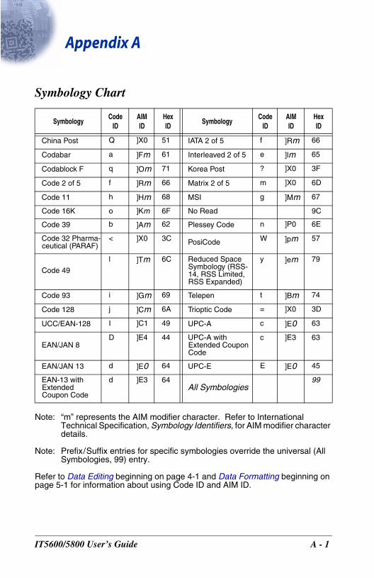
IT560
Appendix A
Symbology Chart
Note: “m” represents the AIM modifier character. Refer to International Technical Specification, Symbology Identifiers, for AIM modifier character details.
Note: Prefix/Suffix entries for specific symbologies override the universal (All Symbologies, 99) entry.
Refer to Data Editing beginning on page 4-1 and Data Formatting beginning on page 5-1 for information about using Code ID and AIM ID.
SymbologyCode
IDAIMID
HexID
SymbologyCode
IDAIMID
HexID
China Post Q ]X0 51 IATA 2 of 5 f ]Rm 66
Codabar a ]Fm 61 Interleaved 2 of 5 e ]lm 65
Codablock F q ]Om 71 Korea Post ? ]X0 3F
Code 2 of 5 f ]Rm 66 Matrix 2 of 5 m ]X0 6D
Code 11 h ]Hm 68 MSI g ]Mm 67
Code 16K o ]Km 6F No Read 9C
Code 39 b ]Am 62 Plessey Code n ]P0 6E
Code 32 Pharma-ceutical (PARAF)
< ]X0 3C PosiCode W ]pm 57
Code 49
l ]Tm 6C Reduced Space Symbology (RSS-14, RSS Limited, RSS Expanded)
y ]em 79
Code 93 i ]Gm 69 Telepen t ]Bm 74
Code 128 j ]Cm 6A Trioptic Code = ]X0 3D
UCC/EAN-128 I ]C1 49 UPC-A c ]E0 63
EAN/JAN 8D ]E4 44 UPC-A with
Extended Coupon Code
c ]E3 63
EAN/JAN 13 d ]E0 64 UPC-E E ]E0 45
EAN-13 with Extended Coupon Code
d ]E3 64All Symbologies
99
0/5800 User’s Guide A - 1
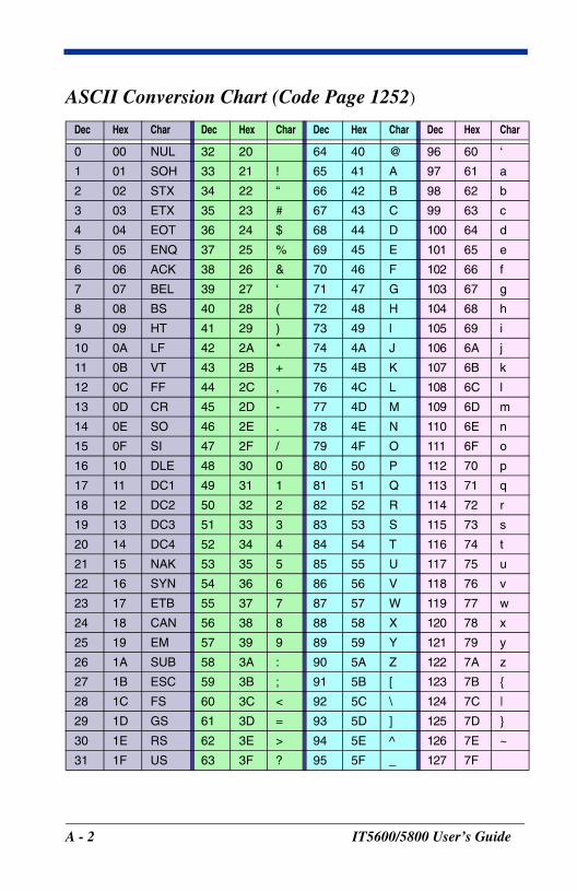
ASCII Conversion Chart (Code Page 1252)
Dec Hex Char Dec Hex Char Dec Hex Char Dec Hex Char
0 00 NUL 32 20 64 40 @ 96 60 ‘
1 01 SOH 33 21 ! 65 41 A 97 61 a
2 02 STX 34 22 “ 66 42 B 98 62 b
3 03 ETX 35 23 # 67 43 C 99 63 c
4 04 EOT 36 24 $ 68 44 D 100 64 d
5 05 ENQ 37 25 % 69 45 E 101 65 e
6 06 ACK 38 26 & 70 46 F 102 66 f
7 07 BEL 39 27 ‘ 71 47 G 103 67 g
8 08 BS 40 28 ( 72 48 H 104 68 h
9 09 HT 41 29 ) 73 49 l 105 69 i
10 0A LF 42 2A * 74 4A J 106 6A j
11 0B VT 43 2B + 75 4B K 107 6B k
12 0C FF 44 2C , 76 4C L 108 6C l
13 0D CR 45 2D - 77 4D M 109 6D m
14 0E SO 46 2E . 78 4E N 110 6E n
15 0F SI 47 2F / 79 4F O 111 6F o
16 10 DLE 48 30 0 80 50 P 112 70 p
17 11 DC1 49 31 1 81 51 Q 113 71 q
18 12 DC2 50 32 2 82 52 R 114 72 r
19 13 DC3 51 33 3 83 53 S 115 73 s
20 14 DC4 52 34 4 84 54 T 116 74 t
21 15 NAK 53 35 5 85 55 U 117 75 u
22 16 SYN 54 36 6 86 56 V 118 76 v
23 17 ETB 55 37 7 87 57 W 119 77 w
24 18 CAN 56 38 8 88 58 X 120 78 x
25 19 EM 57 39 9 89 59 Y 121 79 y
26 1A SUB 58 3A : 90 5A Z 122 7A z
27 1B ESC 59 3B ; 91 5B [ 123 7B {
28 1C FS 60 3C < 92 5C \ 124 7C |
29 1D GS 61 3D = 93 5D ] 125 7D }
30 1E RS 62 3E > 94 5E ^ 126 7E ~
31 1F US 63 3F ? 95 5F _ 127 7F
A - 2 IT5600/5800 User’s Guide
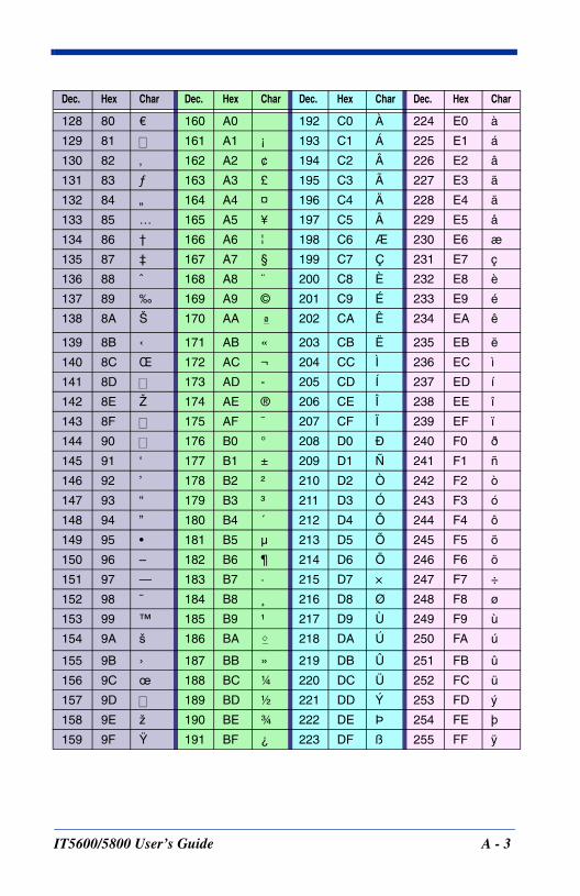
Dec. Hex Char Dec. Hex Char Dec. Hex Char Dec. Hex Char
128 80 €€ 160 A0 192 C0 À 224 E0 à
129 81 161 A1 ¡ 193 C1 Á 225 E1 á
130 82 ‚ 162 A2 ¢ 194 C2 Â 226 E2 â
131 83 ƒ 163 A3 £ 195 C3 Ã 227 E3 ã
132 84 „ 164 A4 ¤ 196 C4 Ä 228 E4 ä
133 85 … 165 A5 ¥ 197 C5 Å 229 E5 å
134 86 † 166 A6 ¦ 198 C6 Æ 230 E6 æ
135 87 ‡ 167 A7 § 199 C7 Ç 231 E7 ç
136 88 ˆ 168 A8 ¨ 200 C8 È 232 E8 è
137 89 ‰ 169 A9 © 201 C9 É 233 E9 é
138 8A Š 170 AA 202 CA Ê 234 EA ê
139 8B ‹ 171 AB « 203 CB Ë 235 EB ë
140 8C Œ 172 AC ¬ 204 CC Ì 236 EC ì
141 8D 173 AD - 205 CD Í 237 ED í
142 8E Ž 174 AE ® 206 CE Î 238 EE î
143 8F 175 AF ¯ 207 CF Ï 239 EF ï
144 90 176 B0 ° 208 D0 Ð 240 F0 ð
145 91 ‘ 177 B1 ± 209 D1 Ñ 241 F1 ñ
146 92 ’ 178 B2 ² 210 D2 Ò 242 F2 ò
147 93 “ 179 B3 ³ 211 D3 Ó 243 F3 ó
148 94 ” 180 B4 ´ 212 D4 Ô 244 F4 ô
149 95 • 181 B5 µ 213 D5 Õ 245 F5 õ
150 96 – 182 B6 ¶ 214 D6 Ö 246 F6 ö
151 97 — 183 B7 · 215 D7 × 247 F7 ÷
152 98 ˜ 184 B8 ¸ 216 D8 Ø 248 F8 ø
153 99 ™ 185 B9 ¹ 217 D9 Ù 249 F9 ù
154 9A š 186 BA 218 DA Ú 250 FA ú
155 9B › 187 BB » 219 DB Û 251 FB û
156 9C œ 188 BC ¼ 220 DC Ü 252 FC ü
157 9D 189 BD ½ 221 DD Ý 253 FD ý
158 9E ž 190 BE ¾ 222 DE Þ 254 FE þ
159 9F Ÿ 191 BF ¿ 223 DF ß 255 FF ÿ
ª
IT5600/5800 User’s Guide A - 3
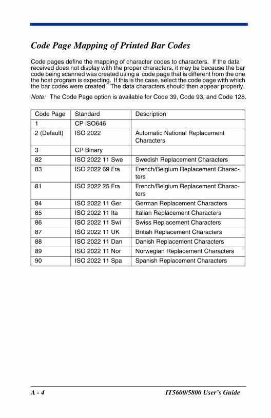
Code Page Mapping of Printed Bar Codes
Code pages define the mapping of character codes to characters. If the data received does not display with the proper characters, it may be because the bar code being scanned was created using a code page that is different from the one the host program is expecting. If this is the case, select the code page with which the bar codes were created. The data characters should then appear properly.
Note: The Code Page option is available for Code 39, Code 93, and Code 128.
Code Page Standard Description
1 CP ISO646
2 (Default) ISO 2022 Automatic National Replacement Characters
3 CP Binary
82 ISO 2022 11 Swe Swedish Replacement Characters
83 ISO 2022 69 Fra French/Belgium Replacement Charac-ters
81 ISO 2022 25 Fra French/Belgium Replacement Charac-ters
84 ISO 2022 11 Ger German Replacement Characters
85 ISO 2022 11 Ita Italian Replacement Characters
86 ISO 2022 11 Swi Swiss Replacement Characters
87 ISO 2022 11 UK British Replacement Characters
88 ISO 2022 11 Dan Danish Replacement Characters
89 ISO 2022 11 Nor Norwegian Replacement Characters
90 ISO 2022 11 Spa Spanish Replacement Characters
A - 4 IT5600/5800 User’s Guide

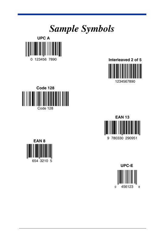
Sample SymbolsUPC A
0 123456 7890 Interleaved 2 of 5
Code 128
EAN 13
1234567890
Code 128
9 780330 290951
654
EAN 8
3210 5
456123 80
UPC-E
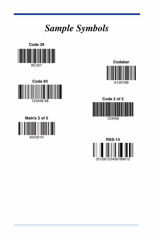
Sample Symbols
Code 93
123456-9$ Code 2 of 5
123456Matrix 2 of 5
6543210RSS-14
(01)00123456789012
Code 39
CodabarBC321
A13579B


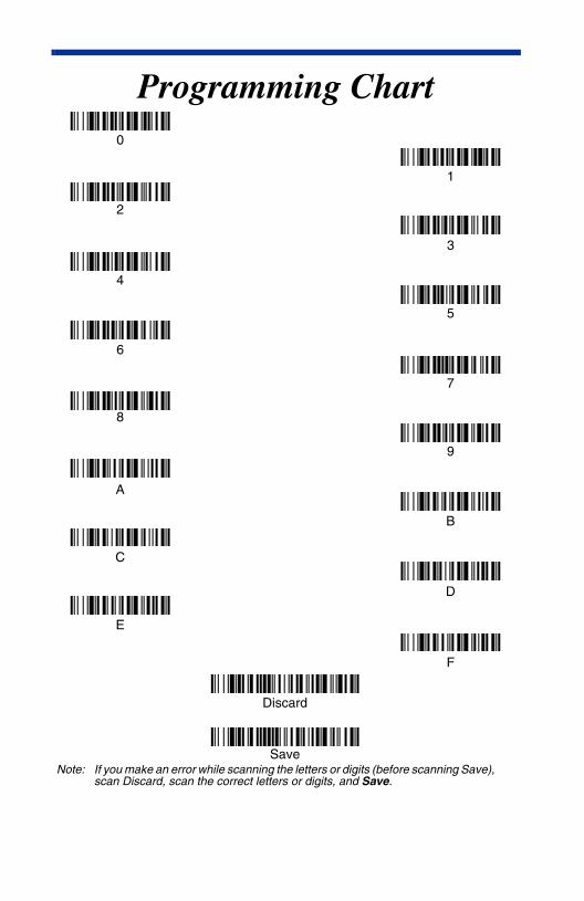
Programming Chart
A
C
Save
B
Discard
F
E
D
Note: If you make an error while scanning the letters or digits (before scanning Save), scan Discard, scan the correct letters or digits, and Save.
0
2
6
1
7
5
4
3
8
9

56/5800/UG Rev B