Embed Size (px)
Citation preview

VITODENS 100-W
Installation and ServiceInstructionsfor use by heating contractor
Vitodens 100-W
WB1A Series
Wall-mounted, natural gas-fired condensing boiler
For natural gasHeating input 29 to 100 MBH
8.5 to 29.3 kW
Read and save these instructions
for future reference.
IMPORTANT
Vitodens 100-W, WB1A(with preinstalled coaxial vent pipeadaptor)
Ple
ase
file
inS
erv
ice
Bin
der
5581 775 v1.3 08/2009

Safety, Installation and Warranty Requirements
2
Safety, Installation and Warranty Requirements
Please ensure that these instructions are read and understood before commencing installation. Failure to comply with the
instructions listed below and details printed in this manual can cause product/property damage, severe personal injury, and/or loss
of life. Ensure all requirements below are understood and fulfilled (including detailed information found in manual subsections).
Licensed professional heating
contractor
The installation, service, andmaintenance of this equipment mustbe performed by a licensedprofessional heating contractor.
Please see section
entitled “Important
Regulatory and
Installation
Requirements” in the
Installation Instructions.
Product documentation
Read all applicable documentation
before commencing installation. Storedocumentation near boiler in a readilyaccessible location for reference inthe future by service personnel.
For a listing of
applicable literature,
please see section
entitled “Important
Regulatory and
Installation Requirements”
in the Installation Instructions.
Advice to owner
Once the installation work iscomplete, the heating contractormust familiarize the systemoperator/ultimate owner with allequipment, as well as safetyprecautions/requirements, shut-downprocedure, and the need forprofessional service annually beforethe heating season begins.
Carbon monoxide
Improper installation, service and/ormaintenance can cause flue productsto flow into living space. Flueproducts contain poisonous carbonmonoxide gas.
For information
pertaining to the proper
installation, service and
maintenance of this
equipment to avoid
formation of carbon monoxide, please
see the Installation Instructions of the
Vitodens Venting System.
Equipment venting
Never operate boiler without aninstalled venting system. An improperventing system can cause carbonmonoxide poisoning.
Warranty
Information contained inthis and related productdocumentation must beread and followed. Failureto do so may render
warranty null and void.
55817751.3
Installers must follow local
regulations with respect to
installation of carbon monoxide
detectors. Follow manufacturer’s
maintenance schedule of boiler.
WARNING

Index
3
Page
Safety Important Regulatory and Installation Requirements 5. . . . . . . . . . . . . . . . . . . . . . . . . . .
General Information About these Installation Instructions 8. . . . . . . . . . . . . . . . . . . . . . . . . . . . . . . . . . . . . . . . . . . . . . . . . . . . . . . . . .
Applicability 9. . . . . . . . . . . . . . . . . . . . . . . . . . . . . . . . . . . . . . . . . . . . . . . . . . . . . . . . . . . . . . . . . . . . . . . . . . . . . . . . . . . . . . . . . . . . . . . . . . . . . . . . . . . .
Product Information 9. . . . . . . . . . . . . . . . . . . . . . . . . . . . . . . . . . . . . . . . . . . . . . . . . . . . . . . . . . . . . . . . . . . . . . . . . . . . . . . . . . . . . . . . . . .
Mechanical Room 10. . . . . . . . . . . . . . . . . . . . . . . . . . . . . . . . . . . . . . . . . . . . . . . . . . . . . . . . . . . . . . . . . . . . . . . . . . . . . . . . . . . . . . . . . . . . . . . .
Set-up Before Set-up 12. . . . . . . . . . . . . . . . . . . . . . . . . . . . . . . . . . . . . . . . . . . . . . . . . . . . . . . . . . . . . . . . . . . . . . . . . . . . . . . . . . . . . . . . . . . . . . . . . . . . . . . . .
Minimum Clearances 12. . . . . . . . . . . . . . . . . . . . . . . . . . . . . . . . . . . . . . . . . . . . . . . . . . . . . . . . . . . . . . . . . . . . . . . . . . . . . . . . . . . . . . . . . . .
Boiler Connections Preparing the Connections 13. . . . . . . . . . . . . . . . . . . . . . . . . . . . . . . . . . . . . . . . . . . . . . . . . . . . . . . . . . . . . . . . . . . . . . . . . . . . . .
Connections overview 13. . . . . . . . . . . . . . . . . . . . . . . . . . . . . . . . . . . . . . . . . . . . . . . . . . . . . . . . . . . . . . . . . . . . . . . . . . . . . . . . . . . . . . . .
Dimensions overview without bottom connections 13. . . . . . . . . . . . . . . . . . . . . . . . . . . . . .
Dimensions overview with connections 13. . . . . . . . . . . . . . . . . . . . . . . . . . . . . . . . . . . . . . . . . . . . . . . . . . . . .
Dimensions overview with connections and alternative drainconnection 13. . . . . . . . . . . . . . . . . . . . . . . . . . . . . . . . . . . . . . . . . . . . . . . . . . . . . . . . . . . . . . . . . . . . . . . . . . . . . . . . . . . . . . . . . . . . . . . . . . . . . . . . . . . . . . .
Wall Mounting 16. . . . . . . . . . . . . . . . . . . . . . . . . . . . . . . . . . . . . . . . . . . . . . . . . . . . . . . . . . . . . . . . . . . . . . . . . . . . . . . . . . . . . . . . . . . . . . . . . . . . . .
Wall mounting bracket installation 16. . . . . . . . . . . . . . . . . . . . . . . . . . . . . . . . . . . . . . . . . . . . . . . . . . . . . . . . . . . . . .
Mounting Vitodens 100-W boiler 18. . . . . . . . . . . . . . . . . . . . . . . . . . . . . . . . . . . . . . . . . . . . . . . . . . . . . . . . . . . . . . . . . .
Connections 18. . . . . . . . . . . . . . . . . . . . . . . . . . . . . . . . . . . . . . . . . . . . . . . . . . . . . . . . . . . . . . . . . . . . . . . . . . . . . . . . . . . . . . . . . . . . . . . . . . . . . . . . . . .
Flue gas connection 18. . . . . . . . . . . . . . . . . . . . . . . . . . . . . . . . . . . . . . . . . . . . . . . . . . . . . . . . . . . . . . . . . . . . . . . . . . . . . . . . . . . . . . . . . . .
Proper piping practice 19. . . . . . . . . . . . . . . . . . . . . . . . . . . . . . . . . . . . . . . . . . . . . . . . . . . . . . . . . . . . . . . . . . . . . . . . . . . . . . . . . . . . . . . . .
Gas connection and piping 19. . . . . . . . . . . . . . . . . . . . . . . . . . . . . . . . . . . . . . . . . . . . . . . . . . . . . . . . . . . . . . . . . . . . . . . . . . . . . .
Gas piping pressure test 21. . . . . . . . . . . . . . . . . . . . . . . . . . . . . . . . . . . . . . . . . . . . . . . . . . . . . . . . . . . . . . . . . . . . . . . . . . . . . . . . . . .
Heating water connections 22. . . . . . . . . . . . . . . . . . . . . . . . . . . . . . . . . . . . . . . . . . . . . . . . . . . . . . . . . . . . . . . . . . . . . . . . . . . . .
Condensate connection 23. . . . . . . . . . . . . . . . . . . . . . . . . . . . . . . . . . . . . . . . . . . . . . . . . . . . . . . . . . . . . . . . . . . . . . . . . . . . . . . . . . . .
Fill siphon with water 23. . . . . . . . . . . . . . . . . . . . . . . . . . . . . . . . . . . . . . . . . . . . . . . . . . . . . . . . . . . . . . . . . . . . . . . . . . . . . . . . . . . . . . . . .
Safety Connections and Pressure Testing 24. . . . . . . . . . . . . . . . . . . . . . . . . . . . . . . . . . . . . . . . . . . . . . . . .
Installing safety devices on the boiler 24. . . . . . . . . . . . . . . . . . . . . . . . . . . . . . . . . . . . . . . . . . . . . . . . . . . . . . .
Performing pressure test on the boiler 25. . . . . . . . . . . . . . . . . . . . . . . . . . . . . . . . . . . . . . . . . . . . . . . . . . . . . . . .
Installation Examples 26. . . . . . . . . . . . . . . . . . . . . . . . . . . . . . . . . . . . . . . . . . . . . . . . . . . . . . . . . . . . . . . . . . . . . . . . . . . . . . . . . . . . . . . . .
Boiler in heating/cooling application 34. . . . . . . . . . . . . . . . . . . . . . . . . . . . . . . . . . . . . . . . . . . . . . . . . . . . . . . . . . . . .
Boiler with low water cut-off (remote mounted, field supplied) 35. . . . . .
Low-loss header 36. . . . . . . . . . . . . . . . . . . . . . . . . . . . . . . . . . . . . . . . . . . . . . . . . . . . . . . . . . . . . . . . . . . . . . . . . . . . . . . . . . . . . . . . . . . . . . . . . . . .
Venting Connection 37. . . . . . . . . . . . . . . . . . . . . . . . . . . . . . . . . . . . . . . . . . . . . . . . . . . . . . . . . . . . . . . . . . . . . . . . . . . . . . . . . . . . . . . . . . . .
Control Connections Electrical Connections 37. . . . . . . . . . . . . . . . . . . . . . . . . . . . . . . . . . . . . . . . . . . . . . . . . . . . . . . . . . . . . . . . . . . . . . . . . . . . . . . . . . . . . . .
Removing the control unit and openingthe power pump module 37. . . . . . . . . . . . . . . . . . . . . . . . . . . . . . . . . . . . . . . . . . . . . . . . . . . . . . . . . . . . . . . . . . . . . . . . . . . . . . . . . .
Electrical connections to the power pump module 38. . . . . . . . . . . . . . . . . . . . . . . . . . . . . . . .
Closing the power pump module and reinstalling thecontrol unit 39. . . . . . . . . . . . . . . . . . . . . . . . . . . . . . . . . . . . . . . . . . . . . . . . . . . . . . . . . . . . . . . . . . . . . . . . . . . . . . . . . . . . . . . . . . . . . . . . . . . . . . . . . . . . .
Reinstalling the front cover panel 39. . . . . . . . . . . . . . . . . . . . . . . . . . . . . . . . . . . . . . . . . . . . . . . . . . . . . . . . . . . . . . . .
55817751.3

4
Initial Start-up,
Inspection and MaintenanceNecessary Tools 40. . . . . . . . . . . . . . . . . . . . . . . . . . . . . . . . . . . . . . . . . . . . . . . . . . . . . . . . . . . . . . . . . . . . . . . . . . . . . . . . . . . . . . . . . . . . . . . . . . .
Overview of Controls and Indicators 41. . . . . . . . . . . . . . . . . . . . . . . . . . . . . . . . . . . . . . . . . . . . . . . . . . . . . . . . . . .
Overview of Components 43. . . . . . . . . . . . . . . . . . . . . . . . . . . . . . . . . . . . . . . . . . . . . . . . . . . . . . . . . . . . . . . . . . . . . . . . . . . . . . . . .
Procedure (Overview) 44. . . . . . . . . . . . . . . . . . . . . . . . . . . . . . . . . . . . . . . . . . . . . . . . . . . . . . . . . . . . . . . . . . . . . . . . . . . . . . . . . . . . . . . .
Steps 45. . . . . . . . . . . . . . . . . . . . . . . . . . . . . . . . . . . . . . . . . . . . . . . . . . . . . . . . . . . . . . . . . . . . . . . . . . . . . . . . . . . . . . . . . . . . . . . . . . . . . . . . . . . . . . . . . . . . . . . .
Troubleshooting Troubleshooting Steps 60. . . . . . . . . . . . . . . . . . . . . . . . . . . . . . . . . . . . . . . . . . . . . . . . . . . . . . . . . . . . . . . . . . . . . . . . . . . . . . . . . . . . . .
Overview of Controls and Indicators 60. . . . . . . . . . . . . . . . . . . . . . . . . . . . . . . . . . . . . . . . . . . . . . . . . . . . . . . . . .
Changing Room Temperature 61. . . . . . . . . . . . . . . . . . . . . . . . . . . . . . . . . . . . . . . . . . . . . . . . . . . . . . . . . . . . . . . . . . . . . . . .
Diagnosis 62. . . . . . . . . . . . . . . . . . . . . . . . . . . . . . . . . . . . . . . . . . . . . . . . . . . . . . . . . . . . . . . . . . . . . . . . . . . . . . . . . . . . . . . . . . . . . . . . . . . . . . . . . . . . . . . .
Sequence of operation and potential faults during eachstart-up cycle 62. . . . . . . . . . . . . . . . . . . . . . . . . . . . . . . . . . . . . . . . . . . . . . . . . . . . . . . . . . . . . . . . . . . . . . . . . . . . . . . . . . . . . . . . . . . . . . . . . . . . . . . .
Diagnostics table: Faults with fault display on control unit 63. . . . . . . . . . . . .
Correction 65. . . . . . . . . . . . . . . . . . . . . . . . . . . . . . . . . . . . . . . . . . . . . . . . . . . . . . . . . . . . . . . . . . . . . . . . . . . . . . . . . . . . . . . . . . . . . . . . . . . . . . . . . . . . . . .
Remove front cover panel 65. . . . . . . . . . . . . . . . . . . . . . . . . . . . . . . . . . . . . . . . . . . . . . . . . . . . . . . . . . . . . . . . . . . . . . . . . . . . . . .
Check boiler temperature sensor 65. . . . . . . . . . . . . . . . . . . . . . . . . . . . . . . . . . . . . . . . . . . . . . . . . . . . . . . . . . . . . . . . . .
Check fixed high limit 66. . . . . . . . . . . . . . . . . . . . . . . . . . . . . . . . . . . . . . . . . . . . . . . . . . . . . . . . . . . . . . . . . . . . . . . . . . . . . . . . . . . . . . .
Check fuses 67. . . . . . . . . . . . . . . . . . . . . . . . . . . . . . . . . . . . . . . . . . . . . . . . . . . . . . . . . . . . . . . . . . . . . . . . . . . . . . . . . . . . . . . . . . . . . . . . . . . . . . . . . . .
Additional Information Technical Data 68. . . . . . . . . . . . . . . . . . . . . . . . . . . . . . . . . . . . . . . . . . . . . . . . . . . . . . . . . . . . . . . . . . . . . . . . . . . . . . . . . . . . . . . . . . . . . . . . . . . . . .
Burner Program Sequence of Operation 70. . . . . . . . . . . . . . . . . . . . . . . . . . . . . . . . . . . . . . . . . . . . . . . . . . . . .
Wiring Diagram 71. . . . . . . . . . . . . . . . . . . . . . . . . . . . . . . . . . . . . . . . . . . . . . . . . . . . . . . . . . . . . . . . . . . . . . . . . . . . . . . . . . . . . . . . . . . . . . . . . . . . . .
Parts List 72. . . . . . . . . . . . . . . . . . . . . . . . . . . . . . . . . . . . . . . . . . . . . . . . . . . . . . . . . . . . . . . . . . . . . . . . . . . . . . . . . . . . . . . . . . . . . . . . . . . . . . . . . . . . . . . . . .
Maintenance Record 74. . . . . . . . . . . . . . . . . . . . . . . . . . . . . . . . . . . . . . . . . . . . . . . . . . . . . . . . . . . . . . . . . . . . . . . . . . . . . . . . . . . . . . . . . . .
Lighting and Operating Instructions 75. . . . . . . . . . . . . . . . . . . . . . . . . . . . . . . . . . . . . . . . . . . . . . . . . . . . . . . . . . . . .
55817751.3

Safety
5
Important Regulatory and Installation Requirements
Codes
The installation of this unit shall be inaccordance with local codes or, in theabsence of local codes, useCAN/CSA-B149.1 or .2 InstallationCodes for Gas Burning Appliances forCanada. For U.S. installations use theNational Fuel Gas Code ANSI Z223.1.Always use latest editions of codes.
In Canada all electrical wiring is to bedone in accordance with the latestedition of CSA C22.1 Part 1 and/orlocal codes. In the U.S. use theNational Electrical Code ANSI/NFPA70. The heating contractor must alsocomply with both the Standard forControls and Safety Devices forAutomatically Fired Boilers,ANSI/ASME CSD-1, and the InstallationCode for Hydronic Heating Systems,CSA B214-01, where required by theauthority having jurisdiction.
Leave all literature at the installation
site and advise the system
operator/ultimate owner where the
literature can be found. Contact
Viessmann for additional copies.
This product comes with several
safety instruction labels attached.
Do not remove!
Contact Viessmann immediately if
replacement labels are required.
Special Requirements for Side-Wall Vented Appliances
In the Commonwealth of Massachusetts
The Commonwealth of Massachusetts requires compliance with regulation 248 CMR 4.00 and 5.00 for installation ofside-wall vented gas appliances as follows:
(a) For all side-wall horizontally vented gas fueled equipment installed in every dwelling, building or structure used in wholeor in part for residential purposes, including those owned or operated by the Commonwealth and where the side-wallexhaust vent termination is less than (7) feet above finished grade in the area of the venting, including but not limited todecks and porches, the following requirements shall be satisfied:
1. INSTALLATION OF CARBON MONOXIDE DETECTORS. At the time of installation of the side-wall horizontal ventedgas fueled equipment, the installing plumber or gasfitter shall observe that a hard wired carbon monoxide detectorwith an alarm and battery back-up is installed on the floor level where the gas equipment is to be installed. Inaddition, the installing plumber or gasfitter shall observe that a battery operated or hard wired carbon monoxidedetector with an alarm is installed on each additional level of the dwelling, building or structure served by theside-wall horizontal vented gas fueled equipment. It shall be the responsibility of the property owner to secure theservices of qualified licensed professional for the installation of hard-wired carbon monoxide detectors.
a. In the event that the side-wall horizontally vented gas fueled equipment is installed in a crawl space or an attic,the hard-wired carbon monoxide detector with alarm and battery back-up may be installed on the next adjacentfloor level.
b. In the event that the requirements of this subdivision can not be met at the time of completion of installation, theowner shall have a period of thirty (30) days to comply with the above requirements; provided, however, thatduring said thirty (30) day period, a battery operated carbon monoxide detector with an alarm shall be installed.
Continued on following page.
55817751.3

Safety
6
Important Regulatory and Installation Requirements (continued)
2. APPROVED CARBON MONOXIDE DETECTORS. Each carbon monoxide detector as required in accordance with theabove provisions shall comply with NFPA 720 and be ANSI/UL 2034 listed and IAS certified.
3. SIGNAGE. A metal or plastic identification plate shall be permanently mounted to the exterior of the building at aminimum height of eight (8) feet above grade directly in line with the exhaust vent terminal for the horizontally ventedgas fueled heating appliance or equipment. The sign shall read, in print size no less than one-half (1/2) inch in size,”GAS VENT DIRECTLY BELOW. KEEP CLEAR OF ALL OBSTRUCTIONS”.
4. INSPECTION. The state or local gas inspector of the side-wall horizontally vented gas fueled equipment shall notapprove the installation unless, upon inspection, the inspector observes carbon monoxide detectors and signageinstalled in accordance with the provisions of 248 CMR 5.08(2)(a) 1 through 4.
(b) EXEMPTIONS: The following equipment is exempt from 248 CMR 5.08(2)(a) 1 through 4:
1. The equipment listed in Chapter 10 entitled ”Equipment Not Required To Be Vented” in the most current edition ofNFPA 54 as adopted by the Board; and
2. Product Approved side-wall horizontally vented gas fueled equipment installed in a room or structure separate fromthe dwelling, building or structure used in whole or in part for residential purposes.
(c) MANUFACTURER REQUIREMENTS - GAS EQUIPMENT VENTING SYSTEM PROVIDED. When the manufacturer ofProduct Approved side-wall horizontally vented gas equipment provides a venting system design or venting systemcomponents with the equipment, the instructions provided by the manufacturer for installation of the equipment and theventing system shall include:
1. Detailed instructions for the installation of venting system design or the venting system components; and
2. A complete parts list for the venting system design or venting system.
(d) MANUFACTURER REQUIREMENTS - GAS EQUIPMENT VENTING SYSTEM NOT PROVIDED. When the manufacturer of aProduct Approved side-wall horizontally vented gas fueled equipment does not provide the parts for venting the fluegases, but identifies ”special venting systems”, the following requirements shall be satisfied by the manufacturer:
1. The referenced ”special venting system” instructions shall be included with the appliance or equipment installationinstructions; and
2. The ”special venting systems” shall be Product Approved by the Board, and the instructions for that system shallinclude a parts list and detailed installation instructions.
(e) A copy of all installation instructions for all Product Approved side-wall horizontally vented gas fueled equipment, allventing instructions, all parts lists for venting instructions, and/or all venting design instructions shall remain with theappliance or equipment at the completion of the installation.
55817751.3

Safety
7
Important Regulatory and Installation Requirements (continued)
Working on the equipment
The installation, adjustment, service,and maintenance of this boiler must beperformed by a licensed professional
heating contractor who is qualified andexperienced in the installation, service,and maintenance of hot water boilers.There are no user serviceable parts onthe boiler, burners, or control.
Ensure main power supply toequipment, the heating system, and allexternal controls has been deactivated.Close main gas supply valve. Takeprecautions in all instances to avoidaccidental activation of power duringservice work.
The completeness and functionality of
field supplied electrical controls and
components must be verified by the
heating contractor. This includes low
water cut-offs, flow switches (if used),
staging controls, pumps, motorized
valves, air vents, thermostats, etc.
Technical literature
Literature for the Vitodens boiler:- Technical Data Manual- Installation and Service Instructions- Operating Instructionsand User’s Information Manual
- Vitodens Venting System InstallationInstructions
- Instructions of other products utilizedand installed
- Installation codes mentionedin this manual and as locallyapplicable
Leave all literature at the installation
site and advise the system
operator/ultimate owner where the
literature can be found. Contact
Viessmann for additional copies.
This product comes with several
safety instruction labels attached.
Do not remove!
Contact Viessmann immediately if
replacement labels are required.
55817751.3

General Information
8
About these Installation Instructions
Take note of all symbols and notations intended to draw attention to potential hazards or important product information.
These include ”WARNING”, ”CAUTION”, and ”IMPORTANT”. See below.
Warnings draw your attention to the
presence of potential hazards or
important product information.
Cautions draw your attention to the
presence of potential hazards or
important product information.
Helpful hints for installation,
operation or maintenance which
pertain to the product.
This symbol indicates that additional,
pertinent information is to be found in
column three.
This symbol indicates that other
instructions must be referenced.
55817751.3
Indicates an imminently hazardous
situation which, if not avoided, could
result in death, serious injury or
substantial product/property damage.
WARNING
Indicates an imminently hazardous
situation which, if not avoided, may
result in minor injury or
product/property damage.
CAUTION
IMPORTANT

General Information
9
Applicability
Boiler serial number must be provided
when ordering replacement parts.
Both the 16-digit serial number bar
code paper label and the 12-digit
ASME/NB serial number correlate to
each other. Providing either serial
number is sufficient.
Vitodens 100-W, WB1A 8-24, 8-30
Model No. Serial No.WB1A 8-24 7246174
andWB1A 8-30 7246175
Product Information
Natural gas-fired wall-mounted hot water heating boiler for space heating.
For operation with constant (set point) boiler water temperatures in closed loop,forced circulation hot water heating circuits. An external controller is required foroutdoor responsive control and DHW production.
The Vitodens 100-W comes factory set for operation with natural gas, with no
option of conversion to liquid propane.
Boiler model must be selected based on an accurate heat loss calculation of thebuilding. Ensure boiler model is compatible with connected radiation.
Vitodens 100 boilers are 100% factory tested and calibrated. No furtheradjustments are required during field start-up.
To vent this boiler, follow the Vitodens Venting System Installation Instructions.
55817751.3
IMPORTANT
Serial No. location (16-digitbarcode white paper labellocated on the left or rightside of the boiler)
ASME/NB stamp serialnumber location (12-digitmetallic plate riveted on theheat exchanger)

General Information
10
Mechanical Room
During the early stages of new home design, we recommend that properconsideration be given to constructing a separate mechanical room dedicated togas- or oil-fired equipment including domestic hot water storage tanks.
The boiler must be located in a heated indoor space, near a floor drain, and asclose as possible to the wall.
Whenever possible, install boiler near an outside wall so that it is easy to duct theventing system to the boiler.
Locate boiler on walls capable of supporting the weight of the boiler filled withwater (see section entitled “Technical Data” on page 68 for information requiredfor total boiler weight calculation). Ensure that boiler location does not interferewith proper circulation of combustion and ventilation air of other fuel burningequipment (if applicable) within the mechanical room.
The maximum room temperature of the mechanical room where the boiler islocated must not exceed 104°F/40°C.
Boiler operation in marine environments
(damp, salty coastal areas):
The service life of the boiler’s exposedmetallic surfaces, such as the casingand fan housing, is directly influencedby proximity to damp and salty marineenvironments. In such areas, higherconcentration levels of chlorides fromsea spray, coupled with relativehumidity, can lead to degradation ofthe exposed metallic surfacesmentioned above. Therefore, it isimperative that boilers installed in suchenvironments not be installed usingdirect vent systems which drawoutdoor air for combustion. Suchboilers must be installed using room airdependent vent systems; i.e. usingroom air for combustion. The indoor airwill have a much lower relativehumidity and, hence, potentialcorrosion will be minimized.
55817751.3
IMPORTANT

General Information
11
Mechanical Room (continued)
Installation area conditions
Ensure ambient temperatures arehigher than 32°F / 0°C and lowerthan104°F / 40°C.
Prevent the air from becomingcontaminated by halogenatedhydrocarbons (e.g. as contained inpaints solvents or cleaning fluids) andexcessive dust (e.g. through grindingor polishing work).Combustion air for the heatingprocess, and ventilation of the boilerroom must be free of corrosivecontaminants. To that end, any boilermust be installed in an area that hasno chemical exposure.The list to the right indicates themain, currently known sources.
Avoid continuously high levels ofhumidity (e.g. through frequentdrying of laundry).
Never close existing ventilationopenings.
Sources of combustion and ventilation
air contaminants
Areas likely to contain contaminants:
New building construction Swimming pools Remodelling areas, hobby rooms Garages with workshops Furniture refinishing areas Dry cleaning/laundry areas andestablishments
Auto body shops Refrigeration repair shopsMetal fabrication plants Plastic manufacturing plants Photo processing plants Beauty salons
Products containing contaminants:
Chlorine-type bleaches, detergentsand cleaning solvents found inhousehold laundry rooms
Paint and varnish removers Hydrochloric acid, muriatic acid Chlorine-based swimming poolchemicals
Spray cans containingchlorofluorocarbons
Chlorinated waxes and cleaners Cements and glues Refrigerant leaks Calcium chloride used for thawing Sodium chloride used for watersoftening salt
Permanent wave solutions Adhesives used to fasten buildingproducts and other similar items
Antistatic fabric softeners used inclothes dryers
If you notice fire coming from the
appliance, call the fire department
immediately! Do not attempt to
extinguish the fire unless qualified to
do so.
WARNING
Fire causes a risk of burns and
explosion!
Shut down the boiler
Close fuel shut-off valves
Use a tested fire extinguisher,
class ABC.
WARNING
Incorrect ambient conditions can lead
to damage to the heating system and
put safe operation at risk.
WARNING

General Information/Set-up
12
Before Set-up
Before placing boiler in its installationlocation, ensure all necessaryaccessories are installed.
Minimum Clearances
Recommended minimum service clearances
Refer to the illustrations on the left hand side.
Note:The Vitodens 100-W boiler has passed the zeroinches vent clearance to combustibles testingrequirements dictated by the boiler HarmonizedStandard ANSI Z21.13. CSA 4.9.2005 and thereforeis listed for zero clearance to combustibles whenvented with a single wall special venting system(AL-29-4C material) or UL/ULC-listed CPVC gas ventmaterial. The zero inches vent clearance tocombustibles for the Vitodens 100-W boilersupercedes the clearance to combustibles listing thatappears on the special venting system label.
Clearances to combustibles
Top Front Rear Left Right Vent pipe*1
0 0 AL, CL 0 0 0 0
AL = Alcove
CL = Closet*1Refer to the Installation Instructions of the Vitodens
Venting System for details.
The boiler must be installed in such a
way that gas ignition system
components are protected from
water (spraying, splashing, etc.)
during boiler operation and service.
CAUTION
Top clearance -12”.See VitodensVenting SystemInstallationInstructions.12”/300 mm*
4”/100mm 28”/
700 mm
¼”/5 mm ¼”/5 mm¼”/5 mm
Front
12”/305 mm
Top*
12”/305 mm
0”/mm
28”/700 mm
Side
0”/mm
Back
Side

Boiler Connections
13
Preparing the Connections
Use an approved pipe sealant or teflon tape when
connecting the following installation fittings.
Connections overview
This section constitutes an overview only! Refer to subsequent sections for
detailed information on individual piping connections.
Piping connections for Vitodens
100-W, WB1A 8-24 and 8-30 (factory
supplied)
Legend
BWR Boiler water return, ¾”BWS Boiler water supply, ¾”BD Boiler drainBF Boiler fillGC Gas connection, ¾” NPTM
(male thread)PRV Pressure relief valveNPT National Pipe ThreadPG Pressure gageVC Vent connection
55817751.3
BWS
BWR
NPT
GC
PRV
BD
PGBF
VC
NPTNPT

Boiler Connections
14
Preparing the Connections (continued)
Dimensions overview without bottom connections
Connections Vitodens 100-W,
WB1A 8-24, 8-30
Legend
Boiler water supply, NPT ¾” (malethread)Condensate drain, plastic hoseØ 0.87” / 22mmGas connection, NPT ¾” (malethread)Boiler water return, NPT ¾” (malethread)
a 7” / 180 mmb 15¾” / 400 mmc 2¼” or 2 7/16” / 58 mm or 62 mmd 27½” / 700 mme 47/8” / 123 mmf 7¼” / 183 mmg 133/8” / 340 mmh 5” / 125 mm
Vitodens 100-W, WB1A
side view
When preparing gas, water
and electrical connections in
the field, see section entitled
“Wall Mounting” on page 16
of this manual for information
regarding the installation of
the wall mounting bracket.
The maximum ambient temperature
must not exceed 104 ºF/40 ºC.
Heating water connections and gasconnection to be made in the field.See illustration to the left andconnection-specific section fordetails.
See subsection entitled “Powersupply connection” for detailsregarding power supply to theVitodens 100-W boiler.
55817751.3
d
c
he
g
a f
b
e
IMPORTANT

Boiler Connections
15
Preparing the Connections (continued)
Dimensions overview with connections
This section constitutes an overview only! Refer to subsequent sections for
detailed information on individual piping connections.
Piping connections for Vitodens
100-W, WB1A 8-24 and 8-30 (factory
supplied)
Legend
BWR Boiler water return, ¾”BWS Boiler water supply, ¾”BD Boiler drainBF Boiler fillGC Gas connection, ¾” NPTM
(male thread)PRV Pressure relief valvePG Pressure gageVC Venting connection
55817751.3
14” /
355mm
15¾” /
400mm
27/8” / 73mm
53/ 8”/137mm
27½”/700mm
33”/838mm
12”/300mm
2¼”
or2 7/16”/58mm
or
62 mm
6” /152mm 47/8” /
123mm
47/8” /123mm
VC
PRV
BD
GC
PG
BF
BWS
BWR

Boiler Connections
16
Wall Mounting
Wall mounting bracket installation
Legend
Mounting templateFinished floor level
Dimensions
a 12” / 300mmb min. 45” / 1143mm
The Vitodens 100-W can bewall-mounted ona brick/concrete wallwood studsmetal studs
Following are the installationinstructions for the mounting bracketon each material. Skip to theinstallation instructions applicable toyour installation requirements.
Installation of mounting bracket on
brick/concrete wall:
1.Drill holes (Ø 3/8”/10 mm), usingmounting template supplied with theboiler.
2.Align wall mounting bracket andattach to wall with the screws andplastic anchors supplied.
55817751.3
Ø3/8” /10mm
2x
1.
2.
a
b
Whichever mounting method is used,
ensure that the bracket is tightly and
securely fastened to wall. Failure to
secure boiler properly could cause
boiler to loosen, posing a severe
safety hazard.
CAUTION

Boiler Connections
Installation of mounting bracket
a
a = 16”/407 mm
Installation of mounting bracket on wood studs
16”/407 mm
3/16”
2x
Installation of mounting bracket on metal studs
5/8”
2x
16”/407 mm
17
Wall Mounting (continued)
Mounting bracket installation (continued)
Installation of mounting bracket on
wood and metal studs
To mount the Vitodens 100-W boileron wood or metal studs, installmounting bracket on wall as shown onprevious page.Refer to drawings on the left andbelow for more detailed installationinformation.
Install mounting bracket on wood studsas per illustration.Drill 3/16” pilot holes to insert mountingbolts.Ensure that holes are located in thecenter of each wood stud.
Install mounting bracket on metal studsas per illustration.Drill 5/8” pilot holes to insert mountingbolts.Ensure that holes are located in thecenter of each metal stud.Secure mounting bracket with bolts tometal studs as shown.
55817751.3

Boiler ConnectionsBoiler Connections
18
Wall Mounting (continued)
Mounting Vitodens 100-W boiler
1. Remove the screw at the top ofboiler.
2. Press down on springs at bottom ofboiler and remove the frontenclosure panel.
3. Remove front enclosure panel.
4.Mount boiler onto the mountingbracket.
For installation of the
mounting bracket, see
subsection entitled “Wall
mounting bracket
installation” on page 16 of
this manual.
Connections
Flue gas connection
Combustion airFlue gases
The Vitodens 100-W boiler comes witha preinstalled vent pipe adaptor (asshown).Run venting system, single-pipe,double-pipe or coaxial, through the sidewall or the roof, taking the shortestpossible route and at a rising angle(min. 3º).
Read and follow the
Installation Instructions
Vitodens Venting System for
details.
55817751.3
55817751.3

Boiler Connections
19
Connections (continued)
Proper piping practice
Support piping by proper suspensionmethod. Piping must not rest on or besupported by boiler.
Gas connection and piping
Legend
Water supply connectionCondensate drain connectionGas connectionWater return connection
1.Make gas connection in accordancewith codes CAN/CSA B149.1 orNational Fuel Gas Code ANSIZ223.1/NFPA 54, as well as localcodes where applicable.
2.Close gas shutoff valve on boiler.
3. Perform leak test.
4. Bleed air from gas supply pipe.
See following page for details on gasconnection and piping.
55817751.3
Use moderate amount of dope
Leave 2 end threads bareThread pipe right length
2 imperfect threads
¨
z z

Boiler Connections
20
Connections (continued)
Gas connection and piping (continued)
Legend
Gas connectionAccessible manual gas shutoff(factory supplied)Drip leg
Max. gas supply pressure: 14 “w.c.
1. Refer to current CAN/CSA B149.1 orNational Fuel Gas Code ANSIZ223.1/NFPA 54, as well as localcodes for gas piping requirementsand sizing. Pipe size to the boilermust be determined based on:– pipe length– number of fittings– maximum input requirements of allgas appliances in the residence.
Design piping layout in such a way that
piping does not interfere with
serviceable components.
2. Before connecting boiler to gas line,install ground joint union, cappeddrip leg and a manual equipmentshutoff valve. Valves must be listedby a nationally recognized testingagency. Make boiler gas connectionas shown on the left.
Gas connection (NPT) ∅¾“. . . . . . . . . . . . . . . . . . .
3. Perform gas piping pressure test asdescribed in the followingsubsection.
4. Identify shutoff valves as such witha tab and familiarizeoperator/ultimate owner of boilerwith these valves.
55817751.3
55817751.3
IMPORTANT
The gas supply piping must be leak
tested before placing the boiler in
operation.
WARNING
Ensure that gas piping is large
enough for all appliances in the
residence. No noticeable gas
pressure drop in the gas line must
occur when any unit (or combination
of units) lights or runs.
CAUTION
IMPORTANT

Boiler Connections
21
Connections (continued)
Gas piping pressure test
When performing the gas piping pressure test, ensure the following requirements aremet.
½ psig = 14 ”w.c.
1. Isolate the boiler from the gas supplypiping system using the individualmanual shutoff valve during pressuretests equal to or less than ½ psig/14 ”w.c.
2. The boiler and its individual shutoffvalve must be disconnected from thegas supply piping system during anypressure testing of that system attest pressures in excess of½ psig/14 ”w.c.
3. Perform leak test.Use approved liquid spray solutionfor bubble test. Ensure that no liquidis sprayed on any electricalcomponents, wires or connectors.Do not allow leak detection fluid tocontact gas valve regulator orregulator vent opening.
4.Correct any and all deficiencies.
5. Remove air from gas line.
55817751.3
Never check for gas leaks with an
open flame.
WARNING
Exposing boiler gas pressure
regulator and gas valve to extreme
pressures renders warranty null and
void.
WARNING
IMPORTANT

Boiler Connections
22
Connections (continued)
Heating water connections
Legend
BWR Boiler water return, ¾”BWS Boiler water supply, ¾”BD Boiler drainBF Boiler fillGC Gas connection, ¾” NPTMPRV Pressure relief valveNPT National Pipe ThreadPG Pressure gage
1. Thoroughly flush heating system(particularly before connecting theboiler to an existing system).
2.Connect boiler to the heatingsystem.
Max. operating pressure 3 bar/. . . . .
45 psig. . . . . . . . . . . . . . . . . . . . . . . . . . . . . . . . . . . . . . . . . . . . . . . . . . . . . . . .
Test pressure 4 bar/. . . . . . . . . . . . . . . . . . . . . . . . . . .
60 psig. . . . . . . . . . . . . . . . . . . . . . . . . . . . . . . . . . . . . . . . . . . . . . . . . . . . . . . .
Damage resulting from pressure
exceeding those values stated is not
covered by Viessmann warranty.
Use a two-hand wrench methodwhen tightening fittings or pipingonto the boiler connectors. Use onewrench to prevent the boiler pipesfrom twisting and the second wrenchto tighten the fitting or piping.Failure to support the boilerconnection could damage the boilerand its internal piping.
All plumbing must meet or exceed alllocal state and national plumbingcodes.
SUPPORT ALL PIPING USINGHANGERS. DO NOT support piping bythe unit or its components.
Use isolation valves to isolate systemcomponents.
55817751.3
55817751.3
BWS
BWR
NPT
GC
PRV
BD
PG
BF
IMPORTANT
IMPORTANT

Boiler Connections
23
Connections (continued)
Condensate connection
Flexible discharge tubingDischarge tubing
The Vitodens 100-W boiler comes witha built-in condensate trap. An externaltrap is not required when connectingthe field drain to flexible dischargetubing. Discharge tubing (field supplied)must be of 1” diameter. Use CPVC,PVC or other material approved bycodes listed below.In the U.S. the drain pipe and fittingsmust conform to ANSI standards andASTM D1785 or D2846. CPVC or PVCcement and primer must conform toASTM D2564 or F493. In Canada useCSA or ULC listed schedule 40 CPVCor PVC drain pipe, fittings and cement.If the condensate outlet of theVitodens 100-W boiler is lower thanthe drain, a condensate pump must beinstalled. Select a pump which isapproved for condensing boilerapplications. To avoid condensatespillage, select a pump with anoverflow switch. The drain connectionmust terminate into an open or venteddrain as close to the boiler as possibleto prevent siphoning of the boiler drain.
1. Install the condensate drain pipewith a suitable gradient.
2.Discharge condensate from theboiler into the drainage system,either directly or (if required) via aneutralization unit (accessory).
Installation Instructions of
Neutralization Unit
(if applicable)
Pipe ventilation must take place
between the siphon trap and the
neutralization unit (if applicable).
Do not connect the drain pipe from any
other appliance, such as water softener
backwash pipe, to Vitodens
condensate drain pipe.
Fill Siphon with water
Fill a minimum of 10 fl.oz. / 0.3 litersof water into the boiler adaptor.
55817751.3
IMPORTANT
IMPORTANT
At initial start-up, flue gases may be
emitted from the condensate drain.
Fill the siphon with water before
start-up.
WARNING

Boiler Connections
24
Safety Connections and Pressure Testing
Installing safety devices on the boiler
Legend
Pressure relief valve (30 psig),¾” NPTBrass nipple, length 2” x ¾”Drain valve connection, ¾”Tee, ¾”x¾”x¾”Brass nipple, length 3” x ¾Reducing tee, ¾”x¾”x¾”Brass nipple, length 2” x ¾Tee, ¼”x¾”x¾”Pressure gage, ¼”Boiler supply connection
1. Remove loosely preassembledcombination pressure relief valve anddrain valve assembly.
2.Apply sufficient amount of pipesealant to both ends of all pipefittings , , and , and installonto tees , and .
3. Install pressure relief valve andtighten.
4. Install discharge pipe on pressurerelief valve in such a way that... the end of the pipe is not threaded. the pressure relief discharge pipeextends to a floor drain and endsapproximately 6”/150 mm abovethe drain.
Ensure that... there is no shutoff valveinstalled in the discharge pipe.
discharge pipe diameter is notreduced.
discharge is not piped tooutdoors.
Minimum connection diameters:Pressure relief valve ¾“. . . . . . . . . . . . . . . . . . . . . . . . . . . .
Discharge pipe ¾“. . . . . . . . . . . . . . . . . . . . . . . . . . . . . . . . . . . . . . . .
Piping to prechargedexpansion tank ¾“. . . . . . . . . . . . . . . . . . . . . . . . . . . . . . . . . . . . . .
Install the (approved) factory supplied
pressure relief valve.
Removal of air from the system must
occur via use of air vent(s) in the
system supply. To ensure the boiler
can be purged of all air, ensure
supply/return water lines do not
contain restrictive piping where air
could be trapped.
Low water cut-off
A low water cut-off may be required by
local codes. If boiler is installed above
radiation level, a low water cut-off
device of approved type (field supplied)
must be installed in all instances. Do
not install an isolation valve between
boiler and low water cut-off (see
subsection entitled “Boiler with low
water cut-off” on page 36 in these
instructions).
55817751.3
IMPORTANT
Do not install an isolation valve
between boiler and pressure relief
valve.
The discharge pipe for the pressure
relief valve must be oriented to
prevent scalding of attendants.
Pipe pressure relief valve discharge
pipe close to floor drain. Never pipe
discharge pipe to the outdoors.
WARNING

Boiler Connections
25
Safety Connections and Pressure Testing (continued)
Performing pressure test on the boiler
The boiler must be leak tested beforebeing placed in operation. Before boileris connected to piping or electricalpower supply, it must behydrostatically pressure tested.
1.Cap supply and return connections(¾” NPT Male).
2.Connect ½” garden hose to boilerdrain valve at the bottom of theboiler and fill boiler slowly untilpressure gage indicates max.4 bar/60 psig.
3.Maintain pressure for 15 minutes.During time of pressure testing, donot leave boiler unattended.
4. Inspect all pipe joint connections andsafety devices with a flashlight forleaks.A lower manometer reading than4 bar/60 psig usually indicates lossof water due to leakage. All leaksmust be repaired.
5.After 15 minutes, release waterpressure from boiler by openingboiler drain valve slowly, removecaps from supply and returnconnections as well as ¾” cap from2” nipple, and install pressure reliefvalve immediately instead of ¾”cap.
After boiler has passed pressuretest, proceed with the installation.
Hot water temperature and system pressure
160ºF
w A
20psi
Hot water temperature reading
The hot water reading is constantlydisplayed during operation.
Pressure reading
1. Turn the knob „tr” to the left on„9”. The display will show theactual system pressure (e.g. 20psig).
2. Turn the knob back to the originalposition.
Note:
When the system pressure falls below8 psig, it will be indicated by a flashingdisplay. If this happens, contact yourheating contractor.
55817751.3
Exposing the boiler to pressures and
temperatures in excess of those
listed will result in damages, and will
render warranty null and void.
WARNING

Boiler Connections
26
Installation Examples
General
The schematics on the following pagesare to be seen as guidelines only. Theyfurther do not display all systemvarieties, safety devices, or conceptspossible. Specific system layouts maybe further discussed with the localViessmann sales representative office.
Clearances
A minimum of 2”/51 mmcircumferential clearance fromnon-insulated hot water pipes tocombustible construction must bemaintained. In cases where the pipesare insulated with pipe insulation ofappropriate and sufficient thicknessand insulation values, the aboveclearance may be reduced to 0” (referto local gas codes).
55817751.3
For underfloor heating applications,
an additional immersion or strap-on
aquastat must be installed in the low
temperature underfloor loop
(downstream of the mixing valve) to
de-energize the pump and/or boiler to
prevent overheating. High water
temperatures can damage concrete
slabs.
CAUTION

Boiler Connections
27
Installation Examples (continued)
Pressure drop (primary circuit) of Vitodens 100-W
Typical System Flow Rates
Model WB1A 8-24 8-30
∆∆∆∆ t for NG
Output (NG) Btu/h 72 000 90 000
20 ºF rise (GPM) 7.2 9.0
25 ºF rise (GPM) 5.8 7.2
30 ºF rise (GPM) 4.8 6.0
35 ºF rise (GPM) 4.1 5.1
40 ºF rise (GPM) 3.6 4.5
Use standard friction loss method for pipe sizing.
Observe boiler maximum and minimum flow rate limitations. If system flow rate exceeds
boiler maximum flow rate (as stated on page 68) or if system flow rate is unknown, Viessmann strongly
recommends the installation of a low-loss header. See page 36 for low-loss header information or refer to the Vitodens
Venting System Installation Instructions.
Important!
The following examples depict possible piping layouts of the Vitodens 100-W boiler equipped with Viessmann System
Technology.
Please note that the examples below are simplified conceptual drawings only!
Piping and necessary componentry must be field verified.
A low water cut-off (LWCO) must be installed where required by local codes.
Proper installation and functionality in the field is the responsibility of the heating contractor.
55817751.3
Pressure drop for model WB1A 8-24, 8-30
0
1
2
3
4
5
6
7
8
0
3.3
6.6
9.8
13.1
16.4
19.7
23
26
Supplyheadpressure
ft.
m
0 2.2 4.4 6.6 8.8 11 13.2
Flow rate
15.41.10 500 1000 1500 2000 2500 3000 3500250 ltr/h
GPM
A low-loss header must be used when the system
flow rate exceeds the maximum (or minimum) flowrate of the Vitodens 100-W boiler. An alternativemethod may be used, such as primary secondarypiping using closely spaced tees.A low-loss header offers additional benefits notprovided by a pair of closely spaced tees. Viess-mann strongly recommends and prefers the use ofa low-loss header over closely spaced tees.

Boiler Connections
28
Installation Examples (continued)
System Layout 1
Vitodens 100-W, WB1A 8-24, 8-30 with...– one heating circuit
System Layout 1 - Alternate Option
Legend
AV Air ventPRV Pressure relief valve
Vitodens 100-WRoom thermostatHeating circuitHeating circuit pump (fieldsupplied)Expansion tank
Ensure that a pressure activated
by-pass is installed. Refer to the table
for the DIP switch setting on page 38.
Please note!The use of a low-loss header isrecommended if the water flow rate is lessthan 1.7 GPM / 400 ltr/h or more than 6.2GPM / 1400 ltr/h.The low-loss header is available asaccessory part.
Model No.
Vitodens 100,
Max. flow rate
(GPM/ltr/h)
WB1A 8-24 6.2/1400
WB1A 8-30 6.2/1400
55817751.3
T--T
PRV
AV
*
T--T
PRV
AV
*
IMPORTANT

Boiler Connections
29
Installation Examples (continued)
System Layout 2
Vitodens 100-W, WB1A 8-24, 8-30 with...– DHW storage tank– low-loss header– one heating circuit
Primary pump must pump into
the boiler (as illustrated).
AV Air ventPRVPressure relief valveTPVTemperature and pressure reliefvalve
Vitodens 100-W gas-firedcondensing boilerExternal boiler/DHW controller(field supplied)Heating circuitHeating circuit pump(field supplied)DHW storage tankDHW tank temperature aquastat orsensorDHW circulating pump (fieldsupplied)Low-loss headerExpansion tankPrimary pump (boiler circuit, fieldsupplied) with low-loss header only
Please note!The use of a low-loss header isrecommended if the water flow rate isless than 1.7 GPM / 400 ltr/h or more
than 6.2 GPM / 1400 ltr/h.The low-loss header is available asaccessory part.See page 36 in this manual for detailson the low-loss header.
Model No.
Vitodens 100-W,
Max. flow rate
(GPM/ltr/h)
WB1A 8-24 6.2/1400
WB1A 8-30 6.2/1400
DHW supply and return piping between boiler DHW connections and the Viessmann DHW tank connections, shall be a
minimum of 1” nominal pipe diameter (irrespective of the ¾” DHW connection outlet sizes provided on the boiler and the
DHW tank). This will ensure pump head is fully utilized to overcome the resistance of the DHW heat exchanger coil and to
provide sufficient water flow to the boiler heat exchanger.
In non-Viessmann DHW tank applications, perform, in addition to the above, accurate calculations for DHW tank coil
pressure drop versus boiler pump head to ensure sufficient water flow to the boiler heat exchanger. Failure to heed the
above instructions may cause boiler short-cycling and inadequate DHW supply.
55817751.3
AV
PRV
TPV
Y
Y
IMPORTANT
IMPORTANT

Boiler Connections
30
Installation Examples (continued)
System Layout 3
Vitodens 100-W, WB1A 8-24, 8-30 with...– DHW storage tank– one heating circuit
Primary pump must pump into
the boiler (as illustrated).
AV Air ventPRVPressure relief valveTPVTemperature and pressure reliefvalve
Vitodens 100-W gas-firedcondensing boilerExternal boiler/DHW controller(field supplied)Heating circuitHeating circuit pump(field supplied)DHW storage tankDHW tank temperature aquastat orsensorDHW circulating pump(field supplied)Closely spaced tees, 4xpipe Øor 12” /305mm*
Expansion tankPrimary pump (boiler circuit, fieldsupplied)
*A low-loss header offers additionalbenefits not provided by a pair ofclosely spaced tees. Viessmannstrongly recommends and prefers theuse of a low-loss header over closelyspaced tees.
Please see page 36 for details.
Please note!The use of a low-loss header isrecommended if the water flow rate isless than 1.7 GPM / 400 ltr/h or more
than 6.2 GPM / 1400 ltr/h.The low-loss header is available asaccessory part.See page 36 in this manual for detailson the low-loss header.
Model No.
Vitodens 100-W,
Max. flow rate
(GPM/ltr/h)
WB1A 8-24 6.2/1400
WB1A 8-30 6.2/1400
DHW supply and return piping between boiler DHW connections and the Viessmann DHW tank connections, shall be a
minimum of 1” nominal pipe diameter (irrespective of the ¾” DHW connection outlet sizes provided on the boiler and the
DHW tank). This will ensure pump head is fully utilized to overcome the resistance of the DHW heat exchanger coil and to
provide sufficient water flow to the boiler heat exchanger.
In non-Viessmann DHW tank applications, perform, in addition to the above, accurate calculations for DHW tank coil
pressure drop versus boiler pump head to ensure sufficient water flow to the boiler heat exchanger. Failure to heed the
above instructions may cause boiler short-cycling and inadequate DHW supply.
55817751.3
AV
PRV
TPV
Y
Y
4xpipe Ø
or 12” /305mm
IMPORTANT
IMPORTANT

Boiler Connections
31
Installation Examples (continued)
Wiring diagram for system layout 4
55817751.3

Boiler Connections
32
Installation Examples (continued)
System Layout 4
Vitodens 100-W, WB1A 8-24, 8-30 with...– DHW storage tank– Low-loss header– one high-temperature heating circuit– one low-temperature heating circuit– Viessmann Vitotronic 050, HK1M controller
Legend
Legend
55817751.3
M
O
D
I
F
N
EB
J
H
K
C
R
G
A
Q
P
A1
B1
D1
C1
See next page for notes andexplanation of this drawing.
A1
B1
D1
C1
A Boiler power pump modulePrimary pump (boiler PPM control)(field supplied)
B Honeywell switching relay forheating circuit EHeating circuit pump(field supplied)
C Honeywell switching relay forDHW H controlDHW circulating pump (fieldsupplied)
D Vitotronic 050, Model HK1MDigital indoor / outdoor heatingcircuit control unit & pump controlVi. Part No. 7134 627
Heating circuit pump (fieldsupplied)
E Radiator heating circuitF Underfloor heating circuitG Low loss header
-Max. flow 17.5 USGPMVi. Part No. 7134 791-Max. flow 35 USGPMVi. Part No. 7134 792
H DHW indirect storage tankI Outdoor temperature sensorJ Limit thermostat (optional)
See note 1
K DHW tank aquastat, HoneywellPart No. L4008A1031,Vi. Part No. 9560 985
M Mixing valve motor / controlN Mixing valve supply temperature
sensorO Viessmann mixing valveP Room thermostat (optional)
See note 2.Q Vitodens 100 boilerR Expansion tank

Boiler Connections
33
Installation Examples (continued)
Installation of heating circuits:- radiator heating circuit (hightemperature circuit)
- underfloor heating circuit with 3-waymixing valve (low temperature circuit)
- DHW production with the followingflow conditions:
The flow rate of the heating circuits isgreater than the maximum possiblewater flow rate of the Vitodens 100boiler.The use of a low-loss header istherefore recommended.A low-loss header is available as anaccessory part.
The radiator heating circuit is suppliedby a circulation pump (field supplied).The underfloor heating circuit issupplied by a circulation pump installedon site which is controlled by theextension kit. The DHW pump is fieldsupplied.
Please note!The use of a low-loss header isrecommended if the water flow rate isless than 1.7 GPM / 400 ltr/h or more
than 6.2 GPM / 1400 ltr/h.The low-loss header is available asaccessory part. See page 36 in thismanual for details on the low-lossheader.
Note 1Optional high limit safety control ofheating circuit E.(During DHW production with STterminal activated, the boiler supplytemperature will be set automaticallyto 78ºC / 172ºF.The heating system must be protectedfrom excessive temperature if noautomatic mixing valves are used or noDHW priority is required.After the DHW call for heat is satisfied,there is a 80 seconds pump post purgetime.
Model No.
Vitodens 100-W,
Max. flow rate
(GPM/ltr/h)
WB1A 8-24 6.2/1400
WB1A 8-30 6.2/1400
Note 2The heating circuit pump logic outputof the Vitotronic 050 is used toenergize the T.T. output of PPM.Therefore, using a room thermostat inseries with RT input of the boiler willreduce unnecessary calls initiated bypump logic output of the Vitotronic tothe Vitodens 100 boiler (mixing valveheating circuit only).
Note 3During DHW call for heat, there is nopriority on mixing valve heating circuit.
DHW supply and return piping between boiler DHW connections and the Viessmann DHW tank connections, shall be a
minimum of 1” nominal pipe diameter (irrespective of the ¾” DHW connection outlet sizes provided on the boiler and the
DHW tank). This will ensure pump head is fully utilized to overcome the resistance of the DHW heat exchanger coil and to
provide sufficient water flow to the boiler heat exchanger.
In non-Viessmann DHW tank applications, perform, in addition to the above, accurate calculations for DHW tank coil
pressure drop versus boiler pump head to ensure sufficient water flow to the boiler heat exchanger. Failure to heed the
above instructions may cause boiler short-cycling and inadequate DHW supply.
55817751.3
IMPORTANT

Boiler Connections
34
Installation Examples (continued)
Boiler in heating/cooling application
Heating/Cooling unitSpring-loaded flow check valveCirculation pumpExpansion tankWater chillerBoiler circuit pump (field supplied)
Viessmann strongly suggests that the
valves pictured above be labelled “v1”
and “v2”.
The boiler, when used in connectionwith a refrigeration system, must beinstalled ensuring the chilled medium ispiped in parallel to the boiler withappropriate valves to prevent thechilled medium from entering the boiler.See illustration on the left.
The boiler piping system of a hot waterheating boiler connected to heatingcoils located in air handling units wherethey may be exposed to refrigerated aircirculation must be equipped with flowcontrol valves or other automaticmeans to prevent gravity circulation ofthe boiler water during the coolingcycle.
Check installation instructions of thechiller manufacturer carefully foradditional requirements.
Cooling season starts:
Close valve v1 and open valve v2.
Heating season starts:
Close valve v2 and open valve v1.
55817751.3
v2
v1
IMPORTANT

Boiler Connections
35
Installation Examples (continued)
Boiler with low water cut-off (remote-mounted, field supplied)
A low water cut-off may be required bylocal codes. If boiler is installed aboveradiation level, a low water cut-offdevice of approved type (field supplied)must be installed in all instances at thehighest point of the piping system. Donot install an isolation valve betweenboiler and low water cut-off.
Follow the installation instructions ofthe low water cut-off manufacturer.
For low water cut-off wiringinformation specific to your application,refer to applicable wiring diagram onthe boiler enclosure panel.
Note:
The Vitodens 100-W boiler has a
built-in flow switch, which may be
accepted by local codes in lieu of a low
water cutoff.
55817751.3
55817751.3
Boiler below radiation
Vitodens 100-W
LWCO
Hi-Vent
Boiler above radiation
Vitodens 100-W
LWCO
Hi-Vent
Boiler Connections
36
Installation Examples (continued)
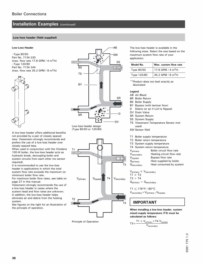
Low-loss header (field supplied)
Low-Loss Header
–Type 80/50Part No. 7134 230(max. flow rate 17.6 GPM / 4 m3/h)–Type 120/80Part No. 7134 244(max. flow rate 35.2 GPM / 8 m3/h)
A low-loss header offers additional benefitsnot provided by a pair of closely spacedtees. Viessmann strongly recommends andprefers the use of a low-loss header overclosely spaced tees.When used in conjunction with the Vitodens100-W boiler, the low-loss header acts ashydraulic break, decoupling boiler andsystem circuits from each other (no sensorrequired).It is recommended to use the low-lossheader in applications in which the totalsystem flow rate exceeds the maximum (orminimum) boiler flow rate.For maximum boiler flow rates, see table onpage 27 in this manual.Viessmann strongly recommends the use ofa low-loss header in cases where thesystem head and flow rates are unknown.In addition, the low-loss header helpseliminate air and debris from the heatingsystem.See figures on the right for an illustration ofthe principle of operation.
The low-loss header is available in the
following sizes. Select the size based on the
maximum system flow rate of your
application.
Model No. Max. system flow rate
Type 80/50 17.6 GPM / 4 m3/h
Type 120/80 35.2 GPM / 8 m3/h
*1Product does not look exactly as
illustrated.
Legend
AB Air Bleed
BR Boiler Return
BS Boiler Supply
BY Bypass (with laminar flow)
D Debris (or air if LLH is flipped)
DV Drain Valve
SR System Return
SS System Supply
TS Viessmann Temperature Sensor (not
used)
SW Sensor Well
T1 Boiler supply temperature
T2 Boiler return temperature
T3 System supply temperature
T4 System return temperature
Vprimary Boiler circuit flow rate
Vsecondary Heating circuit flow rate
Vbypass Bypass flow rate
Qprimary Heat supplied by boiler
Qsecondary Heat consumed by system
Vprimary< VsecondaryT1 > T3
T2 = T4
Qprimary = Qsecondary
T1 ± 176°F / 80°C
Vsecondary=Vprimary+Vbypass
When installing a low-loss header, system
mixed supply temperature (T3) must be
calculated as follows:
T3=T1×Vprimary+T4 Vbypass
Vsecondary
55817751.3
DV
BS
SS
SR
BR
TS
BY
AB
D
Low-loss header design(Type 80/50 or 120/80)
SW
T1
T2
Vprimary Vsecondary
T3
T4
Principle of Operation
T4Vbypass
IMPORTANT

Boiler Connections
37
Venting Connection
For detailed installation information andspecific venting requirements,reference the Vitodens Venting SystemInstallation Instructions supplied withthe boiler.
Installation Instructions
Vitodens Venting System
CAUTIONUnder certain climatic conditions some building materials may be affected by flue products expelled in close proximity tounprotected surfaces. Sealing or shielding of the exposed surfaces with a corrosion resistant material (e.g. aluminumsheeting) may be required to prevent staining or deterioration. The protective material should be attached and sealed (ifnecessary) to the building before attaching the vent termination. It is strongly recommended to install the vent terminationon the leeward side of the building.
Electrical Connections
Removing the control unit and opening the power pump module
1. Flip control unit down and outtowards you. The control unit is heldin place with a spring loaded clip A.
2. Slide unit to the left to remove.
3.Unlock 4 spring loaded lock screwsB and remove power pump modulecover plate.
Both the control unit and the power
pump module have labels and stickers
containing important information. Read
and follow their respective instructions.
Note on connection of accessories
For details regarding other installation steps required, please reference the
Installation Instructions supplied with the respective approved accessory
part.
55817751.3
A
B
IMPORTANT

Control Connections
38
Electrical Connections (continued)
Electrical connections to the power pump module
X2 X4 1 2 3 4X3 L N N L
120V PUMP RT
Note:Boilers are factory shipped witha wiring diagram (11”x17” pageinside a pouch) attached to theinside of the front cover. Thewiring diagram shipped with theboiler supercedes the wiring in-formation in this manual.
Provide main power disconnect/service switch as per local coderequirements. Also refer to wiring diagram on page 71.
DHW
Legend
Main power supply(120V, 60Hz, 1 PH).Heating circuit pump (or boilerpump with low-loss headerapplication). See DIP switchselection setting S1 below. (Pumpruns for 10 seconds every 24hours).DHW tank temperature controller /external heat demandRoom temperature thermostat(Anticipator setting 0.2A)
DIP switch settings - S1
Remove short factory test leads from
terminal L, N and Ground before
connecting main power supply to
boiler.
Ensure that pressure activated by-pass
is installed with system layout 1 on
page 28.
Note:If the boiler is operated using a 10VDCmodulating signal...
See separate OpenTherm (OT)
Module Installation
Instructions.
DIP switch settings - S1
Dip switchnumber
Setting Explanation
1 OFF Pump B is ON during callfor heat. After call for heat(RT-Terminal) is satisfiedpump B post-purges for12 mins.After DHW/external heatdemand (ST-Terminal) issatisfied, pump B post-purges for 1.5 minutes (seeimportant note above).
ON Pump B operates continu-ously
2 OFF Do not adjust
3 OFF Do not adjust
4 OFF Do not adjust
55817751.3
S1
Factory default settingsfor S1 DIP switch
1 Dip switch S1
IMPORTANT
IMPORTANT

Control Connections
39
Electrical Connections (continued)
Closing the power pump module and reinstalling the control unit
1. Reinstall power pump module coverplate.
2. Hook in control unit.
3. Flip control upward and lock intoposition.
Reinstalling the front cover panel
1.Hook in front cover panel.
2. Press in bottom portion of frontcover panel until it locks intoposition.
3. Screw in screw at top part of boiler.
Read and follow, where applicable, the
safety instructions of all labels and
stickers attached to boiler surfaces. Do
not remove any of these instructions.
Contact Viessmann if any replacement
labels are required.
55817751.3
Electrical cables may become
damaged if in contact with hot
components.
When running and securing
connecting cables on site, ensure
that the maximum permissible
temperatures of the cables are not
exceeded.
CAUTION
IMPORTANT

Start-up, Inspection and Maintenance
40
Necessary Tools
Special items
Approved leak detection fluid fornatural gas
Pipe joint sealant Garden hose for pressure testing
Testing/analysis equipment
Multimeter to measure0 - 12 A AC
Flue gas analyzer to measure % CO2or O2 (i.e. Bacharach fluid samplersor suitable electronic flue gasanalyzer)
Manometer to measure gas pressure0 to 11 ”w.c. (accurately) and up to28 ”w.c. gas pressure (or anon-electric Magnehelic® manometermay also be utilized)
Stack thermometer 0 to 500 °F /0 to 260 °C
Bacharach calculator or suitabletables to calculate standard(non-condensing) efficiency
Carbon monoxide measuringequipment 0 to 400 ppm
Cleaning supplies
Plastic hand brush Rags
Use only calibrated equipment.
55817751.3

Start-up, Inspection and Maintenance
41
Overview of Controls and Indicators
Legend
tr boiler water temperatureselector dialDisplay, fault and reset buttonLCD displayGas shutoff valvePressure gage
Opening the control unit
Controls and indicators are locatedbehind the hinged front cover.
Control and display elements
The control unit is preset at the factoryfor standard operation. Your heatingsystem is ready for use. The factorypresets may be individually adjusted tosuit your specific requirements.
55817751.3
tr9
psi
tr9
68°/20°C
140°/60°C
176°/80°C
tr9

Start-up, Inspection and Maintenance
42
Overview of Controls and Indicators (continued)
Legend
Display value or fault codeHeating modeBurner in operationCurrent burner firing rateBoiler water temperature in °F(combined with display value)FaultSystem pressure (combined withdisplay value)Emissions test activated (only forlicensed professional heatingcontractor)
55817751.3
psi
SERV
F

Start-up, Inspection and Maintenance
43
Overview of Components
Legend
Fixed high limit, 210°F/99°CIgnition transformer moduleZIG 2/12Flow switch, VK315MP-trapAir pressure switchCondensate hose, 400mmWater pressure sensor
Vent pipe adaptorTest port capBurner mounting flange assemblyBoiler temperature sensorRadial fan RG130, 120/1/60
Air + gas inlet venturiP Gas valve VK4115V, 120/1/60R Air vent w/shutoff base, 3/8”
S Power pump moduleU Control console
55817751.3

Initial Start-up, Inspection and Maintenance
44
Procedure Overview
Start-up steps
Inspection steps
Maintenance steps Page
S I M 1. Fill and vent the heating system 45. . . . . . . . . . . . . . . . . . . . . . . . . . . . . . . . . . . . . . . . . . . . . . . . . . . . . . . . . . . . . . . . . . . . . . . . . . . . . . . . . . . . . . . . . . . . . . . . . . . . . . . . . . . . . . . . . . . . . . . . . . . . . . . . . . . . . . . . . . . .
S 2. Check power supply connection 46. . . . . . . . . . . . . . . . . . . . . . . . . . . . . . . . . . . . . . . . . . . . . . . . . . . . . . . . . . . . . . . . . . . . . . . . . . . . . . . . . . . . . . . . . . . . . . . . . . . . . . . . . . . . . . . . . . . . . . . . . . . . . . . . . . . . . . . . . . . . .
S 3. Select appropriate gas type 47. . . . . . . . . . . . . . . . . . . . . . . . . . . . . . . . . . . . . . . . . . . . . . . . . . . . . . . . . . . . . . . . . . . . . . . . . . . . . . . . . . . . . . . . . . . . . . . . . . . . . . . . . . . . . . . . . . . . . . . . . . . . . . . . . . . . . . . . . . . . . . . . . . . . . .
I M 4. Measure static pressure and running pressure 47. . . . . . . . . . . . . . . . . . . . . . . . . . . . . . . . . . . . . . . . . . . . . . . . . . . . . . . . . . . . . . . . . . . . . . . . . . . . . . . . . . . . . . . . . . . . . . . . . . . . . . . . . . . . . . . . .
S I M 5. How the Vitodens 100-W boiler operates... 49. . . . . . . . . . . . . . . . . . . . . . . . . . . . . . . . . . . . . . . . . . . . . . . . . . . . . . . . . . . . . . . . . . . . . . . . . . . . . . . . . . . . . . . . . . . . . . . . . . . . . . . . . . . . . . . . . . .
I 6. Relais tests 50. . . . . . . . . . . . . . . . . . . . . . . . . . . . . . . . . . . . . . . . . . . . . . . . . . . . . . . . . . . . . . . . . . . . . . . . . . . . . . . . . . . . . . . . . . . . . . . . . . . . . . . . . . . . . . . . . . . . . . . . . . . . . . . . . . . . . . . . . . . . . . . . . . . . . . . . . . . . . . . . . . . . . . . . . . . . . . . . . . . . . . .
S I M 7. Clock natural gas meter 51. . . . . . . . . . . . . . . . . . . . . . . . . . . . . . . . . . . . . . . . . . . . . . . . . . . . . . . . . . . . . . . . . . . . . . . . . . . . . . . . . . . . . . . . . . . . . . . . . . . . . . . . . . . . . . . . . . . . . . . . . . . . . . . . . . . . . . . . . . . . . . . . . . . . . . . . . . . . . .
I 8. Set maximum input 51. . . . . . . . . . . . . . . . . . . . . . . . . . . . . . . . . . . . . . . . . . . . . . . . . . . . . . . . . . . . . . . . . . . . . . . . . . . . . . . . . . . . . . . . . . . . . . . . . . . . . . . . . . . . . . . . . . . . . . . . . . . . . . . . . . . . . . . . . . . . . . . . . . . . . . . . . . . . . . . . . . . . .
I M 9. Check all primary and secondary circuit connections for leaks 52. . . . . . . . . . . . . . . . . . . . . . . . . . . . . . . . . . . . . . . . . . . . . . . . . . . . . . . . . . . . . . . . . . . . . . . . . . . . . . . . .
I M 10. Perform combustion analysis 52. . . . . . . . . . . . . . . . . . . . . . . . . . . . . . . . . . . . . . . . . . . . . . . . . . . . . . . . . . . . . . . . . . . . . . . . . . . . . . . . . . . . . . . . . . . . . . . . . . . . . . . . . . . . . . . . . . . . . . . . . . . . . . . . . . . . . . . . . . . . . . . . .
I 11. Check venting system for leaks (circular air gap measurement)
for sealed combustion, coaxial vent only 53. . . . . . . . . . . . . . . . . . . . . . . . . . . . . . . . . . . . . . . . . . . . . . . . . . . . . . . . . . . . . . . . . . . . . . . . . . . . . . . . . . . . . . . . . . . . . . . . . . . . . . . . . . . . . . . . . . . . . . .
S I M 12. Remove burner 53. . . . . . . . . . . . . . . . . . . . . . . . . . . . . . . . . . . . . . . . . . . . . . . . . . . . . . . . . . . . . . . . . . . . . . . . . . . . . . . . . . . . . . . . . . . . . . . . . . . . . . . . . . . . . . . . . . . . . . . . . . . . . . . . . . . . . . . . . . . . . . . . . . . . . . . . . . . . . . . . . . . . . . . . . . . . .
I M 13. Check burner gasket and cylinder assembly for damage 55. . . . . . . . . . . . . . . . . . . . . . . . . . . . . . . . . . . . . . . . . . . . . . . . . . . . . . . . . . . . . . . . . . . . . . . . . . . . . . . . . . . . . . . . . .
I M 14. Check and adjust ignition and ionization electrodes 55. . . . . . . . . . . . . . . . . . . . . . . . . . . . . . . . . . . . . . . . . . . . . . . . . . . . . . . . . . . . . . . . . . . . . . . . . . . . . . . . . . . . . . . . . . . . .
I M 15. Check condensate drain and clean siphon (P-trap) 56. . . . . . . . . . . . . . . . . . . . . . . . . . . . . . . . . . . . . . . . . . . . . . . . . . . . . . . . . . . . . . . . . . . . . . . . . . . . . . . . . . . . . . . . . . . . . . . . . . . . .
I M 16. Check neutralization unit (if applicable) 56. . . . . . . . . . . . . . . . . . . . . . . . . . . . . . . . . . . . . . . . . . . . . . . . . . . . . . . . . . . . . . . . . . . . . . . . . . . . . . . . . . . . . . . . . . . . . . . . . . . . . . . . . . . . . . . . . . . . . . . . . . .
I 17. Clean combustion chamber/heat exchanger surfaces 57. . . . . . . . . . . . . . . . . . . . . . . . . . . . . . . . . . . . . . . . . . . . . . . . . . . . . . . . . . . . . . . . . . . . . . . . . . . . . . . . . . . . . . . . . . . . . . .
M 18. Check diaphragm expansion tank and system pressure 58. . . . . . . . . . . . . . . . . . . . . . . . . . . . . . . . . . . . . . . . . . . . . . . . . . . . . . . . . . . . . . . . . . . . . . . . . . . . . . . . . . . . . . . . . . . .
I 19. Check functioning of safety valves 58. . . . . . . . . . . . . . . . . . . . . . . . . . . . . . . . . . . . . . . . . . . . . . . . . . . . . . . . . . . . . . . . . . . . . . . . . . . . . . . . . . . . . . . . . . . . . . . . . . . . . . . . . . . . . . . . . . . . . . . . . . . . . . . . . . . .
I 20. Check gas pipes and fittings for leaks 59. . . . . . . . . . . . . . . . . . . . . . . . . . . . . . . . . . . . . . . . . . . . . . . . . . . . . . . . . . . . . . . . . . . . . . . . . . . . . . . . . . . . . . . . . . . . . . . . . . . . . . . . . . . . . . . . . . . . . . . . . . . . .
I 21. Reinstall burner 59. . . . . . . . . . . . . . . . . . . . . . . . . . . . . . . . . . . . . . . . . . . . . . . . . . . . . . . . . . . . . . . . . . . . . . . . . . . . . . . . . . . . . . . . . . . . . . . . . . . . . . . . . . . . . . . . . . . . . . . . . . . . . . . . . . . . . . . . . . . . . . . . . . . . . . . . . . . . . . . . . . . . . . . . . . .
55817751.3

Initial Start-up, Inspection and Maintenance
45
Steps
1. Fill and vent heating systemServiceStart-up
1. Open system isolation valves (ifinstalled).
Please note:
Before filling the heating system with
water, check that all necessary flow
check valves are installed.
2. Check inlet pressure of thediaphragm expansion tank.
If the nitrogen pressure of the
precharged expansion tank is less
than the static pressure of the
system, inflate membrane pressure to
slightly exceed pressure of system.
The static pressure required at the
tank is based upon the static height
of the system. The system fill
pressure value must be equal to the
expansion tank pressure value at
approx. 60 ºF/15.6 ºC.
During fill and removal of air, the boilerpump can be activated. To activate thepump, in less than 2 seconds turnselector dial to stand-by position froma control range (counter-clockwise) andthen right back into the control range(clockwise). The pump will run for 30minutes and cancel the requestautomatically. A rotating digitalsegment will appear on the display (seebelow).
3. To remove debris and/or sludgeensure that the system piping isflushed out. Failure to do so maycause sediment in the boilercausing overheating and damagenot covered by warranty.
4. Optional:
Fill the heating system with waterat the boiler filling tap and drainair completely from the drain tap.
To remove air from the heat exchanger
Connect a hose to the boiler fillingtap and connect the other end tofresh water supply (or heatingmedium).
Open the fresh water supply valveand then open the boiler filling tapslowly to fill the boiler with water.Isolation valves (not shown) toisolate system components must beclosed during fill/bleed process.
Flush the boiler heat exchanger viathe boiler supply and return (for atleast 10 mins.) until all air has beenremoved from the boiler.
When the drain tap begins tobleed water, close the boiler drainvalve and open system isolationvalves.
Continued on following page.
System fill pressure must be
approximately 3 psig higher than the
static head when the system is cold.
Water treatment should be
considered in areas where it is known
that boiler feed water contains a high
mineral content and hardness.
In areas where freezing might occur,
an antifreeze may be added to the
system water to protect the system.
Please adhere to the specifications
given by the antifreeze manufacturer.
Do not use automotive silicate-based
antifreeze. Please observe that an
antifreeze/water mixture may require
a backflow preventer within the
automatic water feed and influence
components such as diaphragm
expansion tanks, radiation, etc. A
40% antifreeze content will provide
freeze-up protection to -10°F/-23°C.
Do not use antifreeze other than
specifically made for hot water
heating systems. System also may
contain components which might be
negatively affected by antifreeze.
Check total system frequently when
filled with antifreeze.
55817751.3
Unsuitable fill water increases the
level of deposits and corrosion, and
may lead to damage to the
equipment.
Thoroughly flush the entire heating
system prior to filling with water.
Only use fill water of potable
quality.
Soften fill water harder than 150
ppm temporary hardness.
Inhibitors or antifreeze additives
suitable for heating systems may
be added manually.
CAUTION

Initial Start-up, Inspection and MaintenanceInitial Start-up, Inspection and Maintenance
46
Steps (continued)
1. Fill and vent heating system (continued)ServiceStart-up
5. Check system pressure.
6. Ensure proper/adequate fuel supplyexists. Open gas shutoff valve.
Max. boileroperating pressure ......45 psigMin. boileroperating pressure ......14 psigPressure relief valve ......30 psig
2. Check power supply connectionServiceStart-up
A power module is supplied with theVitodens 100-W boiler, which requiresa 120 VAC power supply.
The voltage at connector X3 must be120 V (see wiring diagram).
Neutral conductor
The electrical power supply must havea neutral conductor.
In Canada all electrical wiring is to be
done in accordance with the latest
edition of CSA C22.1 Part 1 and/or
local codes. In the U.S. use the
National Electrical Code ANSI/NFPA
70. The heating contractor must also
comply with both the Standard for
Controls and Safety Devices for
Automatically Fired Boilers, ANSI,
ASME CSD-1.
Please note:
The outer conductor ”L” and the
neutral conductor ”N” must not be
interchanged.
See wiring diagram in section entitled
”Additional Information” in this
manual.
55817751.3
IMPORTANT

Initial Start-up, Inspection and Maintenance
47
Steps (continued)
3. Select appropriate gas typeServiceStart-up and Maintenance
The Vitodens 100-W boiler is for use
with gases whose characteristics fall
within the following ranges. Do not use
any other types of gas.
1. Ensure that the fuel type listed onthe boiler rating plate is the correcttype for the installation beingattempted.
2. Record fuel type in MaintenanceRecord on page 74.
Natural gas
Heating value (gross) Btu/ft3 970 to 1100
Specific gravity 0.57 to 0.70
Ultimate carbon dioxide (CO2) % 11.7 to 12.2
4. Measure static pressure and running pressureServiceStart-up and Maintenance
Legend
Inlet gas pressure measurementportOutlet pressure port (connected todifferential pressure switch)Do not remove this screw orattempt to make any adjustmentto the gas valve
Static pressure
1. To measure static and/or runningpressure remove burner cover panelas per the removal and reinstallationinstructions on page 18 in theseinstructions.
2.Close gas shutoff valve.
3. Loosen screw in test nipple A onthe gas combination valve, do notremove completely. Connectmanometer.
4.Open the gas shutoff valve.
5.Measure static pressure. Valuesmust be: 14 “w.c. max. for NG
6. Enter measured value intoMaintenance Record on page 74 inthis manual.
7. Start up boiler, using the on/offservice switch (field supplied).
A CO measurement (see page 50) must
be taken before and after working on
gas appliances to eliminate risks to
health and to guarantee the
satisfactory condition of the system.
The burner is automatically ignited and
starts operation after a safety time has
elapsed.
During initial start-up, the unit may
indicate a fault because of air in the gas
supply pipe. After approx. 5 seconds,
press the burner reset button (see page
60). The ignition procedure is repeated.
This boiler employs a direct spark
ignition system with 3 trials for
ignition.
55817751.3
IMPORTANT
IMPORTANT

Initial Start-up, Inspection and Maintenance
48
Steps (continued)
4. Measure static pressure and running pressure (continued)ServiceStart-up and Maintenance
Running pressure
8. All measurements must be made
under high fire conditions.Measure the running pressure; valuemust be:
Use suitable measuring instruments
calibrated with a minimum resolution
of 0.04 “w.c. for measuring the
running pressure.
Running supply pressure with Corrective action
Natural gas
under 4 ”w.c. Do not attempt adjustment. Call localgas utility to increase pressure.
4 to 14 “w.c. Start up boiler.
over 14 ”w.c. Do not attempt adjustment. Call localgas utility to decrease pressure.Boiler valve must not be exposed topressure over 14 ”w.c.
9. Enter gas type into MaintenanceRecord on page 74 in this manual.
10.Switch off the heating systemon/off service switch (boiler is shutdown), close the gas shutoff valve,remove the manometer andre-tighten the screw in the testnipple A.
11.Open gas shutoff valve and checkthat the test nipple and all gasconnections are gas-tight.
55817751.3
Measuring running gas supply pressure,using test nipple
Ensure that there is no open flame in
the room.
WARNING
Never purge a gas line into a
combustion chamber. Never use
matches, candles, flame, or other
sources of ignition for purpose of
checking leakage. Use a
soap-and-water solution to check for
leakage. A failure to follow this
warning could result in fire,
explosion, personal injury, or death.
WARNING

Initial Start-up, Inspection and Maintenance
49
Steps (continued)
5. How the Vitodens 100-W boiler operates...ServiceStart-up and Maintenance
The Vitodens 100-W boiler uses a premix combustion system, which is designedto deliver a measured air-gas mixture to the burner for complete combustion. Thegas is injected upstream of the blower. The burner and heat exchanger are part ofa forced-draft design. The benefits of forced-draft systems are lower componenttemperatures, direct air-fuel connection (premix) for improved mixing, and longerservice life of the boiler due to mild to moderate ambient conditions.The cylinder burner blower and the combination gas valve are factory calibratedand pre-adjusted for optimum boiler performance at all firing rates through apneumatic link between combustion air and gas flows. Blower speed isautomatically increased or decreased based on heat demand, thereby regulatingthe amount of combustion air drawn. The pneumatic link between air and gasintroduces the required amount of gas for correct combustion to meet the currentheat demand, based on a linear relationship between ∆∆∆∆ P air and ∆∆∆∆ P gas.
Legend
Inlet gas pressure measurementportOutlet pressure port (connected todifferential pressure switch)Do not remove this screw or
attempt to make any adjustment
with inside screw
55817751.3
FOR FACTORY CALIBRATING
PURPOSES, THE COMBINATION GAS
VALVE IS EQUIPPED WITH
ADJUSTMENT SCREW “C”.
DO NOT ATTEMPT TO ADJUST OR
READJUST THESE SCREWS.
ANY ATTEMPT TO TAMPER WITH
FACTORY PRE-ADJUSTED SETTINGS
WILL LEAD TO UNSTABLE OPERATION
AND WILL AFFECT BOILER
WARRANTY.
WARNING

Initial Start-up, Inspection and Maintenance
50
Steps (continued)
6. Relais testsServiceStart-up and Maintenance
The Vitodens 100-W boiler is factorypreset for operation with natural gas. Itis recommended that a CO2 check beperformed at the boiler vent pipeadaptor as part of the initialstart-up/maintenance procedure.
The cylinder burner of the Vitodens100-W is preset. No adjustment orreadjustment of the burner is required.
The CO2 value lies within the range of 6.6 to 10.0% for natural gasThe CO2 value measured must becompared with the above CO2 value.
Note:If step 7 above is not performed, theprocess will end automatically after 30minutes.
If the CO2 value measured lies morethan 1% outside the stated range,perform the following step: Check the venting system for leaks(refer to the Vitodens VentingSystem Installation Instructions).
1. To bring the boiler to a high fireposition, from a 12:00 o’clockposition quickly (in less than 2seconds) turn selector dial “tr“
clockwise to the end, then backagain into the high fire control range(between 12:00 and 4:00 o’clock).See top illustration on left. Turningthe selector dial “tr“ counterclockwise between the 12:00 and8:00 o’clock position will bring theboiler to the low fire position. Seeillustration on bottom left.
2.Check the CO2 content. Should theactual value deviate by more than1% from the above range, check theseals in the balanced flue system.
3. Enter actual values into the servicereport.
4. To bring the boiler to a low fireposition, from a 12:00 o’clockposition quickly (in less than 2seconds) turn selector dial “tr“
clockwise to the end, then backagain into the low fire control range(between 12:00 and 8:00 o’clock).See bottom illustration on left.Turning the selector dial “tr“
clockwise between the 12:00 and4:00 o’clock position will bring theboiler to the high fire position. Seeillustration on top left.
5.Check the CO2 content. Should theactual value deviate by more than1% from the above range, check theseals in the balanced flue system.
6. Enter actual values into the servicereport.
7.Once checked, turn the selector dial“tr“ in less than 2 secondsclockwise to the end and back againinto the control range.
55817751.3
IMPORTANT
Control range - high fire
psi
SERV
F
blinking
Control range - low fire
psi
SERV
F
blinking

Initial Start-up, Inspection and Maintenance
51
Steps (continued)
7. Clock natural gas meterServiceStart-up and Maintenance
Clock natural gas meter to verify input
1.Ensure all other gas equipmentserved by the meter is turned offduring timing of gas input to theVitodens 100-W boiler.
2.Measure the time in seconds it takesfor the boiler to use 10 cu. ft. ofgas. Divide 3600 x 10 by thenumber of seconds and you get thenumber of cu. ft. of gas used perhour. Multiply this number by theheating value of the gas to obtainBtu per hour input.
For example:A Vitodens 100-W, WB1A 8-30 boiler(100 000 Btu/h input) requires 360seconds to use 10 cu. ft. of naturalgas. After contacting the local utility,you find the heating value is e.g.1000 Btu per cu. ft.Therefore,(3600 x 10)/360 x 1000 ≅ 100 000Btu/h input.Therefore, the boiler input is correct.
Burner input formulas
(up to 4500 ft.):
INPUT=(3600÷t) x 1000 wheret=TIME (sec.) for 1 ft.3
INPUT=(3600 x .01 x 1000 x 35.31)÷TwhereT = TIME (sec.) for .01 m3 natural gas
A boiler underfired by 5% is still
acceptable. Do not overfire the boiler.
8. Set maximum inputServiceStart-up
Note:
It is possible to restrict the maximum heating input to match the exact heating
load requirements. You can limit the input via the modulation range.
1. Turn OFF main power supply andguard against accidental reactivation.
2.Unhook the front of the control unitand flip down.
3. Start up the boiler and at thepotentiometer select themaximum boiler input. Check theadjustment for the correspondinggas throughput.
4. Flip up the control unit front andsnap into position.
Note:
The input restriction mentioned above
does not apply when connecting to ST
input terminals (DHW tank / external
heat demand).
55817751.3
IMPORTANT
Always contact your gas utility to
obtain the correct heating value before
clocking the meter.
CAUTION

Initial Start-up, Inspection and Maintenance
52
Steps (continued)
9. Check all primary and secondary circuit connections for leaksServiceStart-up and Maintenance
Check heating system and domestichot water connections (if applicable).Ensure all connections are pressuretight.Correct any leaks found on fittings,pumps, valves, etc.
10. Perform combustion analysisServiceStart-up and Maintenance
A CO measurement (see page 50) must
be taken before and after working on gas
appliances to eliminate risks to health
and to guarantee the satisfactory condition
of the system.
Record the measured combustionvalues in the sequence stated in theMaintenance Record on page 74 in thismanual.
55817751.3
IMPORTANT

Initial Start-up, Inspection and Maintenance
53
Steps (continued)
11. Check venting system for leaks (circular air gap measurement)
For sealed combustion, coaxial vent onlyServiceStart-up and Maintenance
Combustion air measuring point
Viessmann strongly recommends thatthe heating contractor perform asimplified leak test during boilerstart-up. For this purpose it is sufficientto measure the CO2 concentration ofthe combustion air in the coaxial gap ofthe air intake pipe. The vent pipe isconsidered sufficiently leak-proof if aCO2 concentration in the combustionair no higher than 0.2% or an O2concentration no lower than 20.6% ismeasured.
If higher CO2 values or lower O2 valuesare measured, check venting systemthoroughly.
Please note!
The vent pipe adaptor comes with twomeasurement ports, one forcombustion air intake measurementand one for flue gas measurement.
Please note!
This test is not applicable for single -wall venting system (non-sealedcombustion).
12. Remove burnerServiceMaintenance
To ensure continued efficient operation of the boiler, it is recommended that it ischecked and serviced as necessary at regular intervals. The frequency ofservicing will depend on the particular installation conditions and usage but ingeneral once a year should be adequate. Any service work must be carried outby a licensed professional heating contractor.The boiler incorporates a flue sampling point in front of the flue outlet. The fluegases can be analyzed if required. The push fit cap may be removed and asample tube installed. The push fit cap must be replaced after use. The flue gassample will enable the heating contractor to judge whether any major action isrequired. Before commencing any service operation, isolate and secure the mainpower supply against accidental reactivation, and turn off the main gas supply.
1. Remove the screw at the top of theboiler.
2. Press down the springs on theunderside of the boiler.
3. Remove the front panel.
4. Switch off the main power supply.
5.Close gas shutoff valve and secureagainst reopening.
Continued on following page.
55817751.3

Initial Start-up, Inspection and Maintenance
54
Steps (continued)
12. Remove burner (continued)ServiceMaintenance
6.Disconnect electrical cables from gasvalve , and ignition transformerunit .
7. Remove connection hose from airpressure switch.
8. Loosen the fitting on the gasconnection pipe.
9. Loosen four Torx (T-30) screws ,remove burner and disconnect allelectrical cables from blower motor.
55817751.3
To avoid damage to the burner, do
not lay burner on its cylindrical
burner tube.
Failure to heed this caution may
cause damage to the burner tube,
which may lead to improper
operation.
CAUTION

Initial Start-up, Inspection and Maintenance
55
Steps (continued)
13. Check burner gasket and cylinder assembly for damageServiceMaintenance
Check the burner gasket and burner cylinder assembly for damage and
replace if necessay. Replace the burner cylinder assembly if damaged.
1. Remove electrode block .
2. Loosen the three Torx screws andremove the thermal insulation ring.
3. Loosen the four Torx screws andremove burner cylinder assemblyand assembly gasket .
4. Fit and secure new burner cylinderassembly and new assemblygasket .Tighten to a torque of 2.5 lb.ft. /
3.5 Nm using a calibrated torque
wrench.
5. Reinstall thermal insulation ring .
6. Reinstall electrode block .Tighten to a torque of 1.8 lb.ft. /
2.5 Nm using a calibrated torque
wrench.
14. Check and adjust ignition and ionization electrodesServiceMaintenance
1.Check ignition and ionizationelectrode for wear andcontamination.
2.Clean electrodes with a small brushor emory paper.
3.Check clearances. If clearances arenot satisfactory or the electrodes aredamaged, replace electrode blockand gasket and align. Tightenfastening screws for the electrodesto a torque of 1.8 lb.ft. / 2.5 Nmusing a calibrated torque wrench.
Legend
Ignition and ionization electrodesGrounding rod
55817751.3
+2--1
10
Side view
Top view

Initial Start-up, Inspection and Maintenance
56
Steps (continued)
15. Check condensate drain and clean siphon (P-trap)ServiceMaintenance
1.Check the siphon to ensureunimpeded drainage of condensate.
2. Place appropriate containerunderneath siphon .
3. Remove sealing cap and drainsiphon content into the container.
4. Replace the sealing cap w/gasket.
5. Fill the siphon with water bypouring 10 fl.oz. / 0.3L of water intothe combustion chamber.
If the condensate does not drain freely,condensate will accumulate in bottompart of boiler resulting in a burnershut-down (fault message F4). Thecombustion chamber refractory willalso become wet at the bottomportion. Do not restart the boilerimmediately with a wet combustionchamber refractory. This will damagethe refractory. Either dry the refractoryor replace it.
Installation InstructionsNeutralization Unit(if applicable)
16. Check neutralization unit (if applicable) AccessoryServiceMaintenance
1.Check the pH value of thecondensate with a pH measuringstrip. If the pH value is less than6.5, replace granulate.
pH measuring strip is field supplied.
2. If contaminated:Rinse neutralization unit with tapwater.
3.Add granulate as marked.
The granulate is consumed as itneutralizes the condensate. The redmarking indicates the min. filling level.
Installation InstructionsNeutralization Unit
55817751.3
A
B
IMPORTANT
IMPORTANT
IMPORTANT

Initial Start-up, Inspection and Maintenance
57
Steps (continued)
17. Clean combustion chamber/heat exchanger surfacesServiceMaintenance
1. Remove burner cover panel (if stillinstalled) as per the removal andreinstallation instructions on page 53in this manual, and reinstall panelupon completion of service work.
2. If necessary, clean the combustionchamber and heat exchangersurfaces with a brush and/or rinsewith water.Use solvent-free cleaning agents toremove residues: Remove deposits of soot withalkaline agents containing tenside.
Remove coatings and (yellowishbrown) surface discoloration withphosphoric acid-based “Antox 75 EPlus”, or citric acid-basedCitriSurf 3050 by StellarSolutions Inc.
Rinse thoroughly with water.
Please note:
Be careful not to scratch parts which
are in contact with flue gas. Use
plastic brushes, not wire brushes!
The cleaning agents must not contain
hydrocarbon-based solvents or
potassium.
3.Connect electrical cables tocorresponding parts.
Perform leak test.
55817751.3
Follow cleaning agent manufacturer’s
safety instructions and wear
appropriate protective equipment.
WARNING
IMPORTANT

Initial Start-up, Inspection and Maintenance
58
Steps (continued)
18. Check diaphragm expansion tank and system pressureServiceStart-up and Maintenance
Perform check on the system when cold.
1.Drain boiler/system and reducepressure until the manometer readingis ”0”.
2. If the nitrogen pressure of theprecharged expansion tank is lessthan the static pressure of thesystem, inflate membrane pressureto slightly exceed pressure ofsystem.The static pressure required at thetank is based upon the static heightof the system. The system fillpressure value must be equal to theexpansion tank pressure value atapprox. 60 ºF/15.6 ºC.
Example
Static head of 33 ft./10 m
(distance between boiler and
topmost heat emitter surface)
corresponds to a static
pressure of 1 bar/15 psig.
3. Top up with water until fillingpressure is higher than the inletpressure of the diaphragm expansiontank.
With the system cold, the filling
pressure must be approx. 3 psig
higher than the static pressure.
Max. operating pressure:
45 psig. . . . . . . . . . . . . . . . . . . . . . . . . . . . . . . . . . . . . . . .
Min. operating pressure:
14 psig. . . . . . . . . . . . . . . . . . . . . . . . . . . . . . . . . . . . . . . .
4.When starting up the system for thefirst time, mark this value as theminimum filling pressure on themanometer.
A lower manometer reading usually
indicates loss of water due to
leakage. All leaks must be repaired.
19. Check functioning of safety valvesServiceStart-up and Maintenance
Ensure proper operation of low watercut-off(s) (if applicable), pressure reliefvalve, and pump(s).
Check pressure gage, air vent andpressure relief valve. Ensure thatpressure relief valve does not leak andthat it operates in accordance withinformation provided by themanufacturer.
Refer to maintenance instructions
supplied with low water cut-offs,
pumps, etc.
Flush float water type low watercut-offs (if used).
Follow local regulations with respect tobackflow preventers.
If oil-lubricated pumps are used, ensureproper lubrication.
If motorized zone valves are used, referto maintenance instructions providedwith zone valves.
55817751.3

Initial Start-up, Inspection and Maintenance
59
Steps (continued)
20. Check gas pipes and fittings for leaksServiceStart-up and Maintenance
21. Reinstall burnerServiceStart-up and Maintenance
1. Replace electrical cables from fanmotor , mount burner, anddiagonally tighten 4 torque screws
(approx. 3 ft.lbs./4 Nm using acalibrated torque wrench).
2. Insert new gasket and tighten thefitting on the gas connectionpipe.
3. Insert air pressure switch connectionpipe onto the gas valve “OUT”connector (P2 on the switch).
4. Replace electrical cables from gasvalve , and ignition transformerunit .
5.Open gas shutoff valve and switchon power supply.
55817751.3
The gas supply piping must be leak
tested before placing the boiler in
operation.
WARNING
Ensure all joints of gas line are
pressure tight and that gas valves do
not leak when under normal
operating pressure (use approved
leak detection liquid).
CAUTION

60
Troubleshooting Steps
Diagnosis 1. Establish fault message or diagnose behavior of system.
2. Look for corresponding cause of fault in the diagnostics table.
Diagnosis
for faults with fault display on control unit (see below).
Please note:
3. Find corrective action in the table.
Correction 4. Perform corrective action (page 65).
Overview of Controls and Indicators
Legend
tr boiler water temperatureselector dialDisplay, fault and reset buttonLCD display
Opening the control unit
Controls and indicators are locatedbehind the hinged front cover.
Control and display elements
The control unit is preset at the factoryfor standard operation. Your heatingsystem is ready for use. The factorypresets may be individually adjusted tosuit your specific requirements.
55817751.3
Troubleshooting
55817751.3
tr9
tr9
68°/20°C
140°/60°C
176°/80°C

61
Overview of Controls and Indicators (continued)
Legend
Display value or fault codeHeating modeBurner in operationCurrent burner firing rateBoiler water temperature in °F(combined with display value)FaultSystem pressure (combined withdisplay value)Emissions test activated (only forlicensed professional heatingcontractor)
Changing Room Temperature
In case a separate external roomtemperature controller (thermostat) isinstalled, the desired room temperaturewill be adjusted using this device.
Make adjustments using theappropriate operating instructions only.
Please also note:
lf thermostatic radiator valves areinstalled in the room where the controlis installed they must be fully open.
In case the room temperature settingon the separate room temperaturecontroller is not sufficient to achievethe desired room temperature (e.g.during a particularly cold winter), theboiler water temperature can beadjusted accordingly using the boilerwater temperature selector dial tr.
Troubleshooting55817751.3
psi
SERV
F

Water flow switch activatesplug 33.
Check water flow switch. Replaceif necessary.
no
no
noDisplay message
Fault F5/F9
after approx. 51 seconds
Check cabling and plug-in connectors of the
blower , as well as blower itself. Checkproper power supply to the blower.
yes
yes
Fault F5/F9
after approx. 51 seconds
no Check flue gas system and differential airpressure switch.
Differential air pressure switch enablesstart-up.(Close contacts between terminalsX8.7 and X8.8)
104VRAC (DC)
(symbol A appears).
unit and it’s plug-in connections.
Check condensate line and flue gassystem for leaks.
Fault F4
Fault F4
Fault F4
check gas supply pressure.
between brown and blue must be presentduring start-up, plug 35
62 Dia
gnosis
Sequence
of
opera
tion
and
pote
ntia
lfa
ults
durin
geach
sta
rt-up
cycle
Troubleshooting
5581 775 1.3

Troubleshooting
63
Faults are indicated by a flashing faultcode with fault code sysmbol “U” andthe reset button is illuminated.For fault code explanations see thefollowing table.
Diagnostics table: Faults with fault display on control unit
Fault mes-
sage in dis-
play window
System behavior Cause Corrective measures
0b Burner blocked Insufficient water flow.
Incorrect flow direction.Defective flow switch.
Check proper heating circuit pumpsize and operation.Check flow direction.Check flow switch connection cable.
0c Burner blocked Insufficient power supply Contact your local hydro company.
30 Burner blocked Boiler temperature sensor shortedout
Check the boiler temperature sensor(see page 65).
38 Burner blocked Boiler temperature sensor lead break Check the boiler temperature sensor(see page 65).
b1 Control mode Communication fault - internal pro-gramming unit
Check connections and replace thecontrol unit if necessary.
b5 Control mode Internal fault Replace control unit.
e4 Burner blocked Fault with the supply voltage (powerpump module)
Check connections. Replace controlunit.
e5 Burner blocked Internal fault Check ignition and ionization elec-trodes and leads.Press “Reset”.
e6 Burner blocked Water pressure too low Top up water .
f0 Burner blocked Internal fault Replace control unit.
f2 Burner in fault mode Fixed high limit tripped Check the heating system waterlevel. Check the circulation pumpoperation. Vent the heating systemof air. Check the fixed high limit andleads.Press “Reset”.
f3 Burner in fault mode The flame signal is already present atburner start
Check the ionization electrode andleads.Press “Reset”.
f4 Burner in fault mode No flame signal is present Check the ionization electrode andleads, check the gas pressure, checkthe gas combination valve, controlunit and condensate drain see page56).Press “Reset”.
f5 Burner blocked Faulty air pressure switch Check the air pressure switch andthe interconnecting cable.
Check the burner air/gas
mixture damper. Reference the
Burner Damper Replacement
Instructions.
Diagnosis (continued)
55817751.3
55817751.3
tr9

Troubleshooting
64
Diagnosis (continued)
Diagnostics table: Faults with fault display on control unit (continued)
Fault mes-
sage in dis-
play window
System behavior Cause Corrective measures
f7 Burner blocked Faulty water pressure sensor Check the water pressure sensor andthe interconnecting cable.
f8 Burner in fault mode Combination gas valve closes toolate
Check the gas combination valve.Check both air and gas paths.Press “Reset”.
f9 Burner in fault mode Blower speed too low at burner start Check the blower, check the blowercables and supply, check the blowercontrol.Press “Reset”.
fa Burner in fault mode Blower not at stand-still (blowermust be in stand-still when in stand-by mode)
Check the blower, check the blowercables, check the blower control.Press “Reset”.
fd Burner blocked Burner control unit fault Check the ignition electrodes andleads. Check whether a strong inter-ference (EMC) field exists near theequipment.Press “reset”.If the fault is not removed, replacethe control unit.
fe Burner blocked Faulty main PCB If the equipment will not restart afterresetting, replace control unit
18 Burner in fault mode DIP switch S2 is set to “ON” Set DIP switch S2 back to “OFF”
58 Burner in fault mode DIP switch S4 is set to “ON” Set DIP switch S4 back to “OFF”
a9 Non-permanent lock-out(burner in fault mode)
Communication error OpenThermModule
Turn boiler OFF, then ON
Check communication cable on Ter-minals X3.3, X3.4 on boiler controls.Check connection on OT-Module subbase Terminals 12, 13.
Check 24VAC output of PPM of theboiler Terminals X4.3, X4.4 (RT Ter-minals).
Check for 0-10VDC input signal (amin. of 3.0 volts is required to startup the boiler).
55817751.3
55817751.3

Troubleshooting
65
Correction
Remove front cover panel
1. Remove the screw at the top of theboiler.
2. Press down the springs on theunderside of the boiler.
3. Remove the front cover panel.
4. Lift the front cover panel from thewall mounting frame.
Check boiler temperature sensor
1.Disconnect cables from boilertemperature sensorA.
2.Measure resistance of the boilertemperature sensor and comparewith resistance/boiler watertemperature curve shown on theleft.
3. If the value measured differssignificantly, replace the sensor.
55817751.3
A
10
1
50 86 122 158 194 23068 104 140 176 212 248
0.2
0.4
0.6
0.8
2
4
68
20
40
Resistanceink
Boiler water temperature in ºF/ºC
10 30 5020 40 60
70 90 11080 100 120
Ω
The boiler temperature sensor is
immersed in the heating water (risk
of scalding).
Drain the boiler before replacing the
sensor.
WARNING

Troubleshooting
66
Correction (continued)
Check fixed high limit
If the burner control unit cannot be reset after a fault shutdown (F2), even
though the boiler water temperature is below approx. 203°F / 95°C, check the
fixed high limit.
1. Pull the leads from fixed high limit.
2.Check the continuity of the fixedhigh limit with a multimeter.
3. Remove faulty fixed high limit.
4.Coat the replacement fixed high limitwith heat conducting paste andinstall.
5. To reset press “Reset” on thecontrol unit.
55817751.3
A

Troubleshooting
67
Correction (continued)
Check fuses
Power pump module fuse
1. Switch off main power supply.
2. Flip down and remove control unit.
3. Remove power pump module coverplate .
4.Check fuse F1 T6.3A (slow blow).Replacements available formViessmann - package of 10(PN 7815 580).
Control unit fuse
1. Switch off main power supply.
2. Flip down control unit.
3. Remove cover .
4.Check fuse F1 T4.0A (slow blow).Replacements available formViessmann - package of 10(PN 7404 364).
55817751.3
¾”/20mm
¼”/5mm
Fuse F1 T6.3A
A
F1 T4.0A

Additional Information
68
Technical Data
Rated voltage: 120 VACRated frequency: 60 HzRated current: 6.0 A~
Max. ambienttemperature at operation: 32 to 104 ºF
0 to +40 ºCwhen storingand transporting: –4 to +149 ºF
–20 to +65 ºCSetting of adjustableelectronic high limit 176 ºF
80 ºC
Setting of fixed high limitsafety cut-out: 210 ºF(fixed setting) 99 ºC
Main fuse: max. 15 A
Power consumption Burner: max. 105 W Control unit: max. 10 VA
Standard heating boiler
Boiler Model Model No. WB1A 8-24 WB1A 8-30
Natural gas
CSA input
CSA output/DOE*1
heating capacity
MBHkWMBHkW
29-808.5-23.4
26-727.6-21
29-1008.5-29.3
26-907.6-26.4
Net I=B=R rating*2 MBH 63 78
Heat exchanger surface area ft.2
m29.260.86
9.260.86
Min. gas supply pressure
Natural gas “w.c. 4 4
Max. gas supply pressure*3
Natural gas “w.c. 14 14
A.F.U.E. % 95.1 95.1
Weight lbskg
9543
9543
Boiler water content USGltr
0.823.1
0.823.1
Boiler max. flow rate*4 GPMltr/h
6.21400
6.21400
Max. operating pressure
at 210 ºF/99 ºCpsigbar
453
453
Boiler water temperature
–Adjustable high limit (AHL)range
space heating(steady state)DHW production (set
point)
–Fixed high limit (FHL)
ºF/ºCºF/ºC
ºF/ºC
68 to 176/20 to 80172/78
210/99
Boiler connections
Boiler heating supply and returnNPTM (male) “
Pressure relief valve NPTF (female) “Drain valve (male thread)
¾¾¾
¾¾¾
*1 Output based on 140ºF / 60ºC, 120 ºF / 49ºC system supply/return temperature.*2 Net I=B=R rating based on piping and pick-up allowance of 1.15.*3 If the gas supply pressure exceeds the maximum gas supply pressure value, a separate gas pressure regulator must be installed upstream of the
heating system.*4See “Typical System Flow Rates” on page 27 in this manual.
55817751.3

Appendix
69
Technical Data (continued)
Standard heating boiler
Boiler Model Model No. WB1A 8-24 WB1A 8-30
Dimensions
Overall depth
Overall width
Overall height
inchesmminchesmminchesmm
13.434015.740027.6700
13.434015.740027.6700
Gas supply connection NPTF(female)“ ¾ ¾
Flue gas*5
Temperature (at boiler re-turn temperature of86 ºF/30 ºC)–at rated full load–at rated partial load
Temperature (at boiler re-turn temperature of 140ºF/60 ºC)
ºF/ºCºF/ºC
ºF/ºC
127/5390/32
167/75
131/5590/32
172/78
Flue gas value
Mass flow rate (of fluegas)
–at rated full load
–at rated partial load
Available draught
lbs/hkg/hlbs/hkg/h
Pambar
79.236.033.015.0
1001.0
100.145.533.015.0
1001.0
Average condensate
flow rate*6
with natural gas–TS/TR=122/86ºF/50/30ºC
USG/dayltr/day 1.8-2.1
7-82.1-2.4
8-9
Condensate connec-
tion*7hosenozzle∅ in 1 1
Boiler flue gas connec-
tion*8∅
in/mm 23/8/60 23/8/60
Combustion air supply
connection*8outer∅ in/mm 4/100 4/100
*5 Measured flue gas temperature with a combustion air temperature of 68 °F/20 °C.*6 Based on typical boiler cycles, including partial load conditions.*7 Requires 1”/25 mm tubing. See Vitodens 100-W Installation Instructions for details.*8 For detailed information refer to the Vitodens Venting System Installation Instructions (PN 5285 268).
For information regarding other Viessmann System Technology componentry, please reference documentation of respective product.
55817751.3

Additional Information
Call for heat
Flame signal
Ignition
Combination
gas valve
Actual fan
speed
Fan required
signal
Modulationrange
Time (sec)
Pre-ignition timing
(factory-set)
Pre-purge
Safety timing Post-purge
time
Ignition load
if flame exists after gas
valve closure
Post-purge
Stabilization period
max.
51 secmax. 51
sec
factory set 0.3
sec
factory set to
max. 4.9 sec
max. 30 sec factory setmax. 51
sec---
70
Burner Program Sequence of Operation
Flame safeguard program sequence of operation
Phase Explanation
0 Stand by
1 Stand-still statustest
2 Pre-purge speedtest
3 Pre-purge
4 Pre-ignition
5 Ignition
6 Burner in operation:controller active
7 Proof of closuretest / gas valve
8 Post-purge speedtest
9 Post-purge
Phase 0: Stand by
Complete shutdown until the next callfor heat. In this phase both thecombination gas valve and the blowerare not energized.
Phase 1: Stand-still status test (blower)
A call for heat initiates internal blowersensory communications to confirmthat the blower is truly in stand-stillposition. Blower speed measured mustbe< 300 rpm within a 51 second period.
Phase 2: Pre-purge speed test
The air proving switch is tested firstusing the programmed ignition blowerspeed. After the air proving switchtest, the pre-purge speed (or the forcedpre-purge speed) will be controlledwithin a ¦300 rpm tolerance in a 51second period.
Phase 3: Pre-purge
Pre-purge cycle starts within thepre-programmed timing. If air provingswitch opens during this period, theburner will revert back to Phase 1.Also, if at the end of the pre-purgeperiod expected blower speed is notreached, the burner will revert back toPhase 1.
Phase 4: Pre-ignition
The ignition spark is initiated andcontrolled.
Phase 5: Ignition
The gas valve opens during the safetytiming period (4.8 secs.). If a flame isdetected, this phase ends immediatelyin < 4.8 secs. If the flame is notestablished after 3 trials, the burnerwill lock out and will require a manualreset.
Phase 6: Burner operation
At the end of the flame stabilizationperiod (10 sec.), a release formodulation occurs and the burnertemperature controller will take overfrom the flame safeguard.
Phase 7: Combination gas valve proof
of closure test
If during the normal operation of theburner a controlled (or uncontrolled)shut-down occurs, a completemechanical and electrical gas valveproof of closure test will be performedby the flame safeguard. After asuccessful mechanical and electricalproof of closure test, the flamesafeguard will expect that the flame isnot present. If, however, the flameexisted for a period of >30 seconds,the flame safeguard will go intopermanent lock-out.
Phase 8: Post-purge speed test
Both gas valves are closed during thisphase.
Phase 9: Post-purge
Post-purge occurs during theprogrammed period. If the fixed highlimit trips during normal operation, theblower will purge for 10 min. to coolthe heat exchanger.
55817751.3

Additional Information
71
Wiring Diagram
55817751.3
PU
MP
PU
MP
DH
W

Additional Information
72
Parts List
Model No.
Serial No. *1
WB1A 24 7246174
WB1A 30 7246175
Ordering Replacement Parts:
Please provide Model and SerialNumber from rating plate whenordering replacement parts. Orderreplacement components from yourViessmann distributor.
Parts
003Air pressure switch013Gas connection pipe021Gasket set for gas connection
pipe, 17x24x2mm050Burner gasket051Combustion chamber
door refractory052Burner tube053Burner tube gasket054 Ignition and ionization
electrode block058Flapper059Radial fan RG130, 120/1/60060Air+gas inlet venturi Type 002061Gas valve VK4115V, 120/1/60062Burner mounting flange assembly063 Ignition transformer module
ZIG 2/12080Control console081Control housing, rear200Front panel201Spring clip set for front panel202Flip-down cover407Pressure switch hose
Other Parts (not illustrated)300Touch-up spray paint ”Vitowhite”301Touch-up paint stick ”Vitowhite”400 Installation fittings401 Installation / Service Instructions402Operating Instructions403Quick Start-Up Guide404Warranty Sheet Condensing405Parts List
CSA rating plate(with part number)
55817751.3
051
050
052
053
062
054
063
060
013
003
080
081
202
059
021
200
201
201
021
061
058
407

Additional Information
73
Parts List (continued)
Parts
001Fixed high limit, 210ºF/99ºC002Boiler temperature sensor004Test port cap (set of 2)005Vent pipe adaptor006Gasket set for flue gases
(order glue, part 095 below)007Heat exchanger assembly, ASME008Combustion chamber refractory009Support bracket set
for heat exchanger010Condensate hose, 400mm011P-trap012Condensate pipe014Heating supply connection pipe015Heating return connection pipe016Air vent w shut-off base, 3/8”017Water pressure sensor018O-ring set for
heat exchanger, 21x3mm023Sealing grommet set024Sealing grommet025Fastener set for sensors026 Locking clip set for return027Fastener set for return pipe028Fastener set for supply pipe031Flue gasket, 60mm032Flue gasket, 100mm033Flow switch, VK315M084Power/pump module, 120/1/60302Wall-mount bracket
408Boiler drain409Boiler fill410Boiler water return411Boiler water supply412Gas shutoff valve413Pressure gage414Pressure relief valve
Other Parts (not illustrated)019O-ring set for
supply/return, 18x3mm020Gasket set for water
pressure sensor, 10x2mm022Gasket set for P-trap, 19x2mm029Fastener set, 10mm080Connection cable,
power/pump module083Fuse, T4.0A/250V (pkg. of 10)090Wiring harness, X8091Wiring harness, X9092Connecting cable, fan093Connecting cable, gas valve094Connecting cable,
ignition transformer module095Glue
ASME/NB Rating plate(affixed to heat exchanger with 2rivets)5
5817751.3
414
408
413
409
412
411
410
NPT
009
004
006
005
031
032
009
023
027
007
008
016
015011
010
018
025
002
014033
001
028
017
025
084
018
012
023
024
026
302

Additio
nalInformation
74 M
ain
tenance
Record
Setpoint value
max.
14 ”w.c.
4-14 ”w.c.
Never exceed
50 ppm air-free
Never exceed
200 ppm air-free
Service
date:
by:
Service
date:
by:
Service
date:
by:
Service
date:
by:
Service
date:
by:
Service
date:
by:
“w.c.
“w.c.
vol.-%
vol.-%
vol.-%
vol.-%
ppm
ppm
Measurements
Static pressure
Running pressure (supply pressure)
Natural gas
Carbon dioxide content CO2
at lower end of rated input range
(low fire)
at upper end of rated input range
(high fire)
Oxygen content O2
at lower end of rated input range
(low fire)
at upper end of rated input range
(high fire)
Carbon monoxide content CO
at lower end of rated input range
at upper end of rated input range
5581 775 1.3

Additional Information
75
Lighting and Operating Instructions
55817751.3
FOR YOUR SAFETY READ BEFORE OPERATING
W A R N I N G: If you do not follow these instructions exactly, a fire orexplosion may result causing property damage, personal injury or loss of life.
A. This appliance does not have a pilot. It is equippedwith an ignition device which automatically lightsthe burner. Do not try to light the burner by hand.
B. BEFORE OPERATING smell all around theappliance area for gas. Be sure to smell next to thefloor because some gas is heavier than air and willsettle on the floor.WHAT TO DO IF YOU SMELL GAS• Do not try to light any appliance.• Do not touch any electric switch; do not use any
phone in your building.• Immediately call your gas supplier from a
neighbor’s phone. Follow the gas supplier’sinstructions.
• If you cannot reach your gas supplier, call the firedepartment.
C. Use only your hand to push in or turn the gascontrol knob. Never use tools. If the knob will notpush in or turn by hand, don’t try to repair it, call aqualified service technician. Force or attemptedrepair may result in a fire or explosion.
D. Do not use this appliance if any part has beenunder water. Immediately call a qualified servicetechnician to inspect the appliance and to replaceany part of the control system and any gas controlwhich has been under water.
1. STOP! Read the safety information above on thislabel.
2. Set thermostat or other operating control to lowestsetting.
3. Turn off all electric power to the appliance.
4. This device is equipped with an ignition devicewhich automatically lights the burner. Do not try tolight the burner by hand.
5. Close main gas shut-off valve.
6. Wait five (5) minutes to clear out any gas. Thensmell for gas, including near the floor. If you smellgas, STOP! Follow ”B” in the safety informationabove on this label. If you don’t smell gas, go to thenext step.
7. Open main gas shut-off valve.
8. Turn on all electric power to the appliance.
9. Set thermostat or other operating control todesired setting.
10. If the appliance will not operate, follow theinstructions ”To Turn Off Gas To Appliance” andcall your service technician or gas supplier.
TO TURN OFF GAS TO BOILER
1. Set thermostat or other operating control to lowestsetting.
2. Turn off all electric power to the appliance ifservice is to be performed.
3. Close main gas shut-off valve.
OPERATING INSTRUCTIONS
Closed
Open
Manual gas shutoff

Viessmann Manufacturing Company Inc.750 McMurray RoadWaterloo, Ontario • N2V 2G5 • CanadaTel. (519) 885-6300 • Fax (519) 885-0887www.viessmann.ca • [email protected]
Viessmann Manufacturing Company (U.S.) Inc.45 Access RoadWarwick, Rhode Island • 02886 • USATel. (401) 732-0667 • Fax (401) 732-0590www.viessmann-us.com • [email protected]
76
55817751.3
Printedonenvironmentally
friendly
(recycledandrecyclable)paper.
Technicalinformationsubjectto
changewithoutnotice.