Embed Size (px)
Citation preview
FORM NO 45578 (05/09/18)
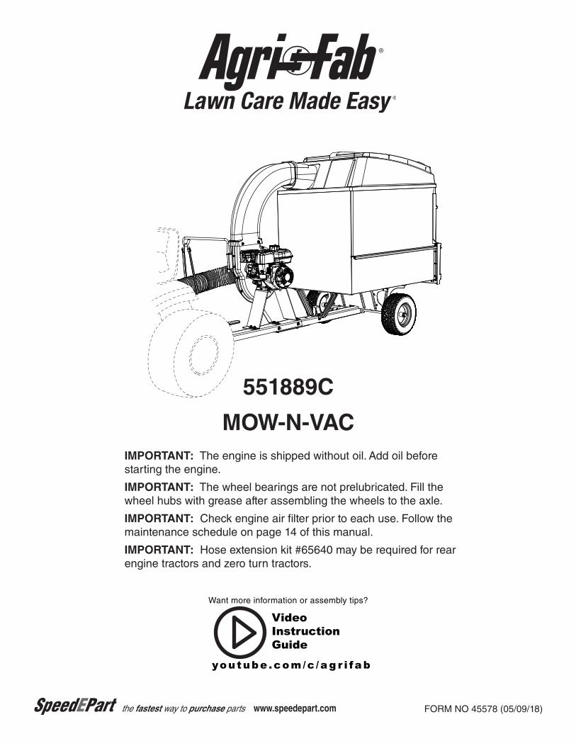
IMPORTANT: The engine is shipped without oil. Add oil before starting the engine.
IMPORTANT: The wheel bearings are not prelubricated. Fill the wheel hubs with grease after assembling the wheels to the axle.
IMPORTANT: Check engine air filter prior to each use. Follow the maintenance schedule on page 14 of this manual.
IMPORTANT: Hose extension kit #65640 may be required for rear engine tractors and zero turn tractors.
551889C
MOW-N-VAC
the fastest way to purchase parts www.speedepart.com
youtube .com/c /a g r i fa b
VideoInstructionGuide
Want more information or assembly tips?
2
TABLE OF CONTENTS
SAFETY RULES .......................................................3,4
FULL SIZE HARDWARE CHART ........................... 5,11
CARTON CONTENTS .................................................6
ASSEMBLY ..................................................................7
OPERATION .............................................................. 13
MAINTENANCE ........................................................ 14
STORAGE ................................................................. 16
TROUBLESHOOTING ............................................... 16
REPAIR PARTS ILLUSTRATIONS ..................17,18,20
REPAIR PARTS LISTS .....................................17,19,20
SLOPE GUIDE ..........................................................21
PARTS ORDERING ...................................................24
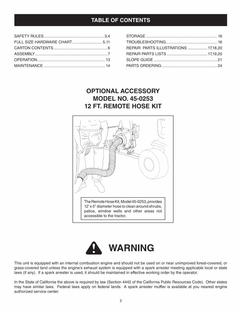
OPTIONAL ACCESSORY MODEL NO. 45-0253
12 FT. REMOTE HOSE KIT
The Remote Hose Kit, Model 45-0253, provides 12' x 5" diameter hose to clean around shrubs, patios, window wells and other areas not accessible to the tractor.
WARNINGThis unit is equipped with an internal combustion engine and should not be used on or near unimproved forest-covered, or grass-covered land unless the engine's exhaust system is equipped with a spark arrester meeting applicable local or state laws (if any). If a spark arrester is used, it should be maintained in effective working order by the operator.
In the State of California the above is required by law (Section 4442 of the California Public Resources Code). Other states may have similar laws. Federal laws apply on federal lands. A spark arrester muffler is available at you nearest engine authorized service center.
3
SAFETY
Any power equipment can cause injury if operated improperly or if the user does not understand how to operate the equipment. Exercise caution at all times, when using power equipment.
• Read and follow all instructions in this manual before attempting to assemble or operate this equipment. Failure to comply with these instructions may result in personal injury. Keep this manual in a safe place for future reference and for ordering replacement parts.
• Read this operating and service instruction manual carefully. Be thoroughly familiar with the controls and proper use of this power vacuum.
• Readthevehicleownersmanualandvehiclesafeoperationrules before using this equipment.
• Never allow children under 16 to operate thisMow-N-Vac.Children 16 years and older should only operate under close parental supervision.
• Donotallowanyonetooperatethisequipmentwithoutproperinstructions.
• Donotallowpassengerstorideonthisequipmentoronthetowing vehicle.
• Keeptheareaofoperationclearofallpersons,particularlysmall children. Also keep area clear of pets.
• Checkfuelbeforestartingengine.Donotfillfueltankindoors,or when engine is running, or while engine is hot. Wipe off any spilled fuel before starting engine.
• Engineandmufflergethot.Donottouch!Toavoidfirehazard,keep clean of debris and other accumulations.
• NeverstoreMow-N-Vacwithfuelintank.Allowenginetocoolbefore storing in any enclosure.
• Donotchangeenginegovernorsettings.• Do not operate engine if air cleaner or cover is removed,
except for adjustment. Removal of these parts could create a fire hazard.
• Keephands,feet,face,longhairandclothingoutofinletanddischarge area. There are ROTATING BLADES inside these openings.
• Beforecleaning,repairingorinspecting,makecertainallmovingparts come to a complete stop. Disconnect spark plug wire and keep wire away from plug to prevent accidental starting. Keep throttle control lever in stop position.
• IftheMow-N-Vacshouldbecomeblockedwithdebrisatanypoint, shut engine off and wait until the impeller comes to a complete stop before attempting to remove the obstruction. Disconnect spark plug wire to prevent accidental starting.
• If thecuttingmechanismstrikesa foreignobject,or if yourMow-N-Vacshouldstarttovibrateabnormally,stoptheengineimmediately, disconnect the spark plug wire and move the wire away from the spark plug. Allow the machine to stop and take the following steps.
a. Inspect for damage. b. Repair or replace any damaged parts. c. Check for loose parts and tighten to assure continued safe operation.• Checkallboltsfortightnessatfrequentintervalstohelpinsure
safe operation.• Checkvinylhardtopbootfrequentlyforwear.Replaceifworn
or damaged.• NeveroperateMow-N-Vacunlessdeckadapter,hose,hose
adapter (nozzle), discharge chute (elbow), and top cover are properly attached in their place.
• Donotremovetopcoverorattempttoemptycontentsofcartwhile engine is running.
• Neverattempttochangehoseadapter(nozzle)orto installremote hose attachment when engine is running.
• Keepallshieldsandguards(e.g.dischargechute(elbow)andhose adapter (nozzle) in place and securely attached.
• Alwayswearsafetyglassesorothersuitableeyeprotectionwhen operating or maintaining this equipment.
• Do not stand behind cart in exhaust discharge areawhileengine is running.
• Donotoperatethisequipmentwhileintoxicatedorwhiletakingdrugs or medication that impairs the senses and reactions.
• Whenusingthisequipment,startwiththevehicletransmissionin first (low) gear and then gradually increase speed only as conditions permit.
• Operatethisequipmentatreducedspeedonroughterrain,along creeks and ditches and on slopes to prevent tipping or loss of control. Do not drive too close to a creek or ditch.
• Vehiclebrakingandstabilityareaffectedby theadditionofthisequipment.DonotfilltheMow-N-Vactoitsfullcapacitywithout checking the capability of the towing vehicle to safely pullandstopwiththeMow-N-Vacattached.
• Beforeoperatingonanygrade(hill)refertothesafetyrulesin the vehicle owner's manual concerning safe operation on slopes. Also refer to the SLOPE GUIDE on page 21 of this owner's manual. Do not operate on slopes in excess of 10 degrees. STAY OFF STEEP SLOPES.
• Follow the maintenance instructions outlined in this manual.
Look for this symbol to point out important safety precautions. It means — Attention!! Become alert!! Your safety is involved.
DANGER: ThisMow-N-Vacwasbuilttobeoperatedaccordingtotherulesforsafeoperationinthismanual. As with any type of power equipment, carelessness or error on the part of the operator can result in serious injury. This unit is capable of amputating fingers and hands and throwing objects. Failure to observe the following safety instructions could result in serious injury or death.
4
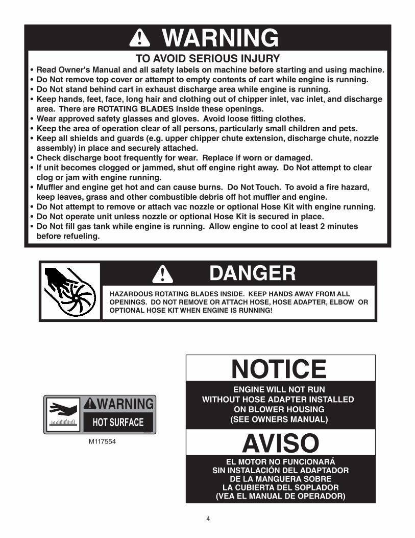
WARNING •ReadOwner'sManualandallsafetylabelsonmachinebeforestartingandusingmachine.•DoNotremovetopcoverorattempttoemptycontentsofcartwhileengineisrunning.•DoNotstandbehindcartinexhaustdischargeareawhileengineisrunning.•Keephands,feet,face,longhairandclothingoutofchipperinlet,vacinlet,anddischarge area.ThereareROTATINGBLADESinsidetheseopenings.•Wearapprovedsafetyglassesandgloves.Avoidloosefittingclothes.•Keeptheareaofoperationclearofallpersons,particularlysmallchildrenandpets.•Keepallshieldsandguards(e.g.upperchipperchuteextension,dischargechute,nozzle assembly)inplaceandsecurelyattached.•Checkdischargebootfrequentlyforwear.Replaceifwornordamaged.• Ifunitbecomescloggedorjammed,shutoffenginerightaway.DoNotattempttoclear clogorjamwithenginerunning.•Mufflerandenginegethotandcancauseburns.DoNotTouch.Toavoidafirehazard, keepleaves,grassandothercombustibledebrisoffhotmufflerandengine.•DoNotattempttoremoveorattachvacnozzleoroptionalHoseKitwithenginerunning.•DoNotoperateunitunlessnozzleoroptionalHoseKitissecuredinplace.•DoNotfillgastankwhileengineisrunning.Allowenginetocoolatleast2minutes beforerefueling.
DANGERHAZARDOUS ROTATING BLADES INSIDE. KEEP HANDS AWAY FROM ALL OPENINGS.DONOTREMOVEORATTACHHOSE,HOSEADAPTER,ELBOWOROPTIONAL HOSE KIT WHEN ENGINE IS RUNNING!
DANGER
TO AVOID SERIOUS INJURY
M117554
5
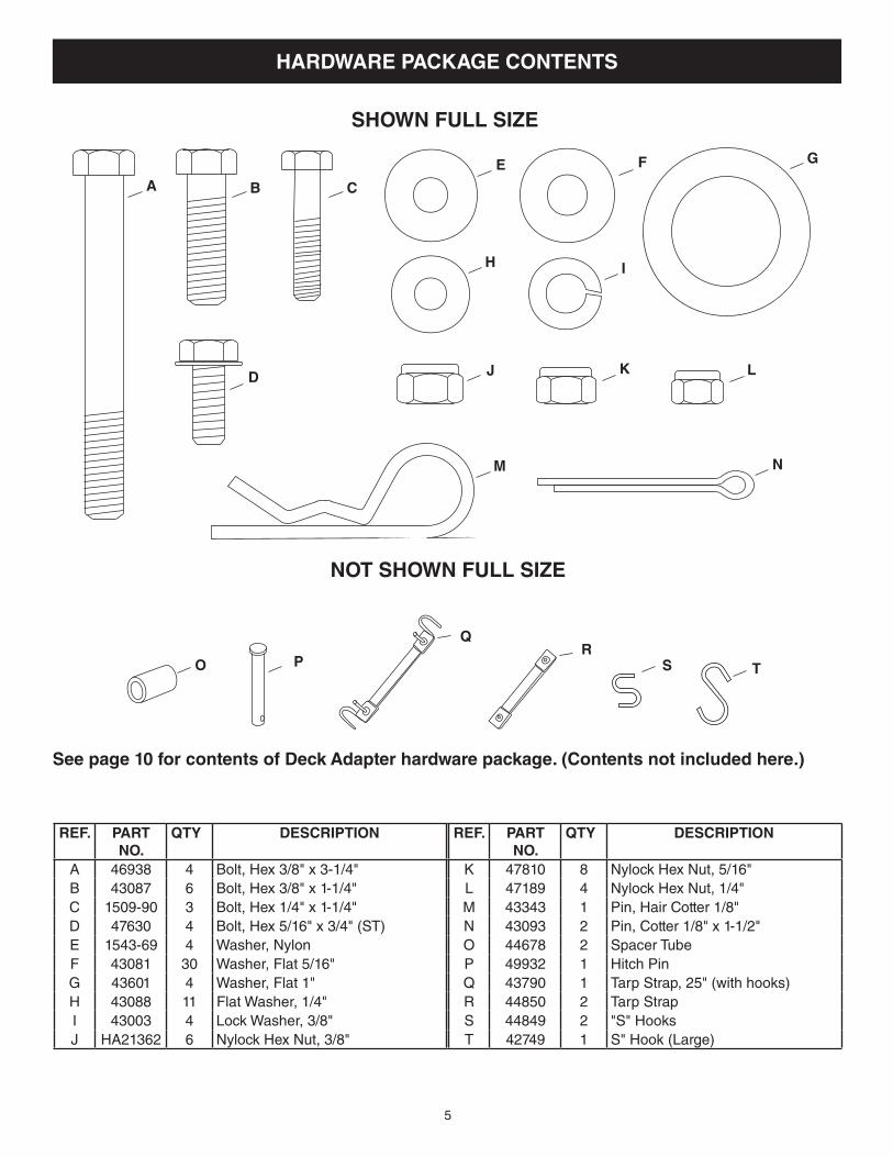
HARDWARE PACKAGE CONTENTS
Seepage10forcontentsofDeckAdapterhardwarepackage.(Contentsnotincludedhere.)
REF. PARTNO.
QTY DESCRIPTION
A 46938 4 Bolt, Hex 3/8" x 3-1/4"B 43087 6 Bolt, Hex 3/8" x 1-1/4"C 1509-90 3 Bolt, Hex 1/4" x 1-1/4"D 47630 4 Bolt, Hex 5/16" x 3/4" (ST)E 1543-69 4 Washer, NylonF 43081 30 Washer, Flat 5/16"G 43601 4 Washer, Flat 1"H 43088 11 Flat Washer, 1/4"I 43003 4 Lock Washer, 3/8"J HA21362 6 Nylock Hex Nut, 3/8"
REF. PARTNO.
QTY DESCRIPTION
K 47810 8 Nylock Hex Nut, 5/16"L 47189 4 Nylock Hex Nut, 1/4"M 43343 1 Pin, Hair Cotter 1/8"N 43093 2 Pin, Cotter 1/8" x 1-1/2"O 44678 2 Spacer TubeP 49932 1 Hitch PinQ 43790 1 Tarp Strap, 25" (with hooks)R 44850 2 Tarp StrapS 44849 2 "S" HooksT 42749 1 S" Hook (Large)
G
D
CBA
I
J
M N
K L
H
SHOWN FULL SIZE
F
NOT SHOWN FULL SIZE
O PR
Q
E
TS
6
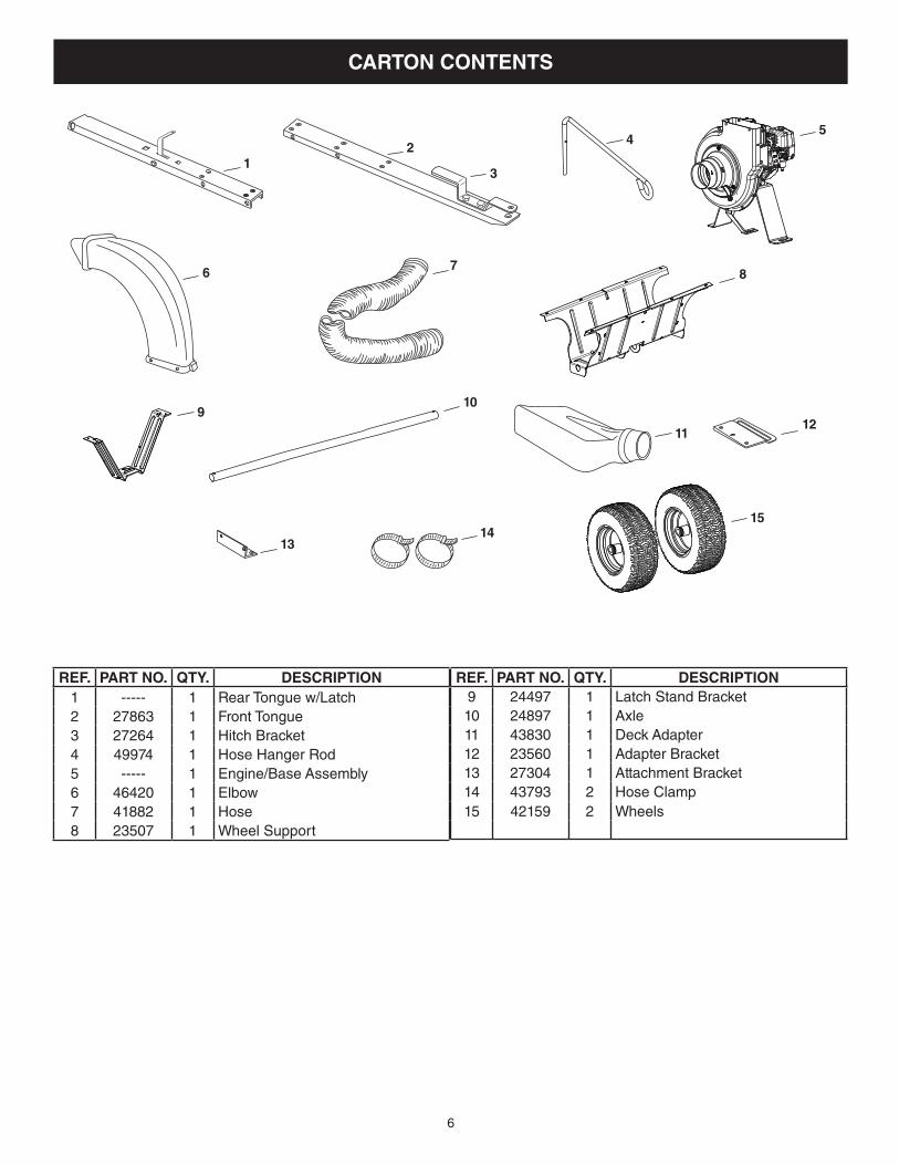
CARTON CONTENTS
10
12
4
3
15
11
9
5
6 7
12
1314
8
REF. PART NO. QTY. DESCRIPTION1 ----- 1 Rear Tongue w/Latch2 27863 1 Front Tongue3 27264 1 Hitch Bracket4 49974 1 Hose Hanger Rod5 ----- 1 Engine/Base Assembly6 46420 1 Elbow7 41882 1 Hose8 23507 1 Wheel Support
REF. PART NO. QTY. DESCRIPTION9 24497 1 Latch Stand Bracket10 24897 1 Axle11 43830 1 Deck Adapter12 23560 1 Adapter Bracket13 27304 1 Attachment Bracket14 43793 2 Hose Clamp15 42159 2 Wheels
7
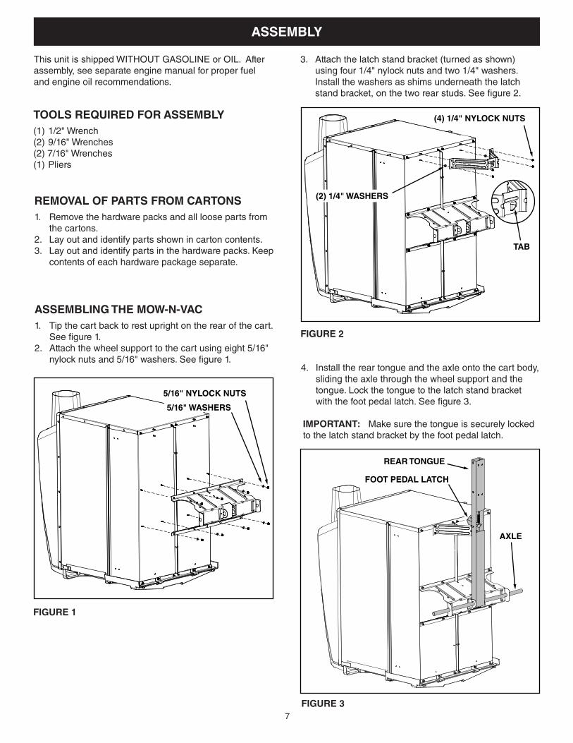
ASSEMBLY
This unit is shipped WITHOUT GASOLINE or OIL. After assembly, see separate engine manual for proper fuel and engine oil recommendations.
TOOLS REQUIRED FOR ASSEMBLY(1) 1/2" Wrench(2) 9/16" Wrenches(2) 7/16" Wrenches(1) Pliers
REMOVAL OF PARTS FROM CARTONS 1. Remove the hardware packs and all loose parts from
the cartons.2. Lay out and identify parts shown in carton contents.3. Lay out and identify parts in the hardware packs. Keep
contents of each hardware package separate.
5/16" NYLOCK NUTS
5/16" WASHERS
ASSEMBLING THE MOW-N-VAC 1. Tip the cart back to rest upright on the rear of the cart.
See figure 1.2. Attach the wheel support to the cart using eight 5/16"
nylock nuts and 5/16" washers. See figure 1.
FIGURE 1
FIGURE 2
3. Attach the latch stand bracket (turned as shown) using four 1/4" nylock nuts and two 1/4" washers. Install the washers as shims underneath the latch stand bracket, on the two rear studs. See figure 2.
(4) 1/4" NYLOCK NUTS
(2) 1/4" WASHERS
TAB
FIGURE 3
4. Install the rear tongue and the axle onto the cart body, sliding the axle through the wheel support and the tongue. Lock the tongue to the latch stand bracket with the foot pedal latch. See figure 3.
IMPORTANT: Make sure the tongue is securely locked to the latch stand bracket by the foot pedal latch.
AXLE
REAR TONGUE
FOOT PEDAL LATCH
8
FIGURE 4
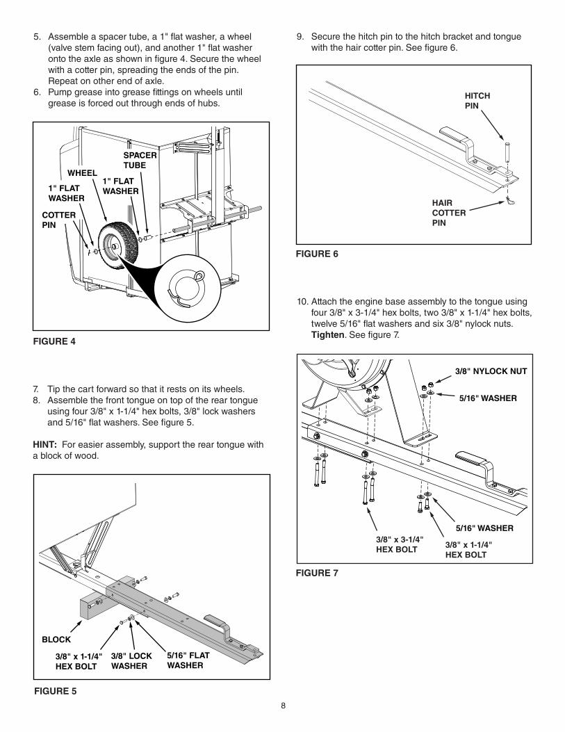
5. Assemble a spacer tube, a 1" flat washer, a wheel (valve stem facing out), and another 1" flat washer onto the axle as shown in figure 4. Secure the wheel with a cotter pin, spreading the ends of the pin. Repeat on other end of axle.
6. Pump grease into grease fittings on wheels until grease is forced out through ends of hubs.
COTTERPIN
WHEEL1" FLATWASHER1" FLAT
WASHER
SPACERTUBE
FIGURE 5
7. Tip the cart forward so that it rests on its wheels.8. Assemble the front tongue on top of the rear tongue
using four 3/8" x 1-1/4" hex bolts, 3/8" lock washers and 5/16" flat washers. See figure 5.
HINT: For easier assembly, support the rear tongue with a block of wood.
BLOCK
3/8" x 1-1/4"HEX BOLT
3/8" LOCKWASHER
5/16" FLATWASHER
9. Secure the hitch pin to the hitch bracket and tongue with the hair cotter pin. See figure 6.
FIGURE 6
HITCHPIN
HAIRCOTTERPIN
10. Attach the engine base assembly to the tongue using four 3/8" x 3-1/4" hex bolts, two 3/8" x 1-1/4" hex bolts, twelve 5/16" flat washers and six 3/8" nylock nuts. Tighten. See figure 7.
FIGURE 7
3/8" x 1-1/4"HEX BOLT
3/8" x 3-1/4"HEX BOLT
5/16" WASHER
5/16" WASHER
3/8" NYLOCK NUT
9
FIGURE 9
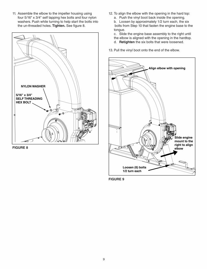
12. To align the elbow with the opening in the hard top: a. Push the vinyl boot back inside the opening. b. Loosen by approximately 1/2 turn each, the six
bolts from Step 10 that fasten the engine base to the tongue.
c. Slide the engine base assembly to the right until the elbow is aligned with the opening in the hardtop.
d. Retighten the six bolts that were loosened.
13. Pull the vinyl boot onto the end of the elbow.
5/16" x 3/4" SELF THREADINGHEX BOLT
NYLON WASHER
FIGURE 8
11. Assemble the elbow to the impeller housing using four 5/16" x 3/4" self tapping hex bolts and four nylon washers. Push while turning to help start the bolts into the un-threaded holes. Tighten. See figure 8.
Loosen (6) bolts1/2 turn each
Align elbow with opening
Slide engine mount to theright to align elbow
10
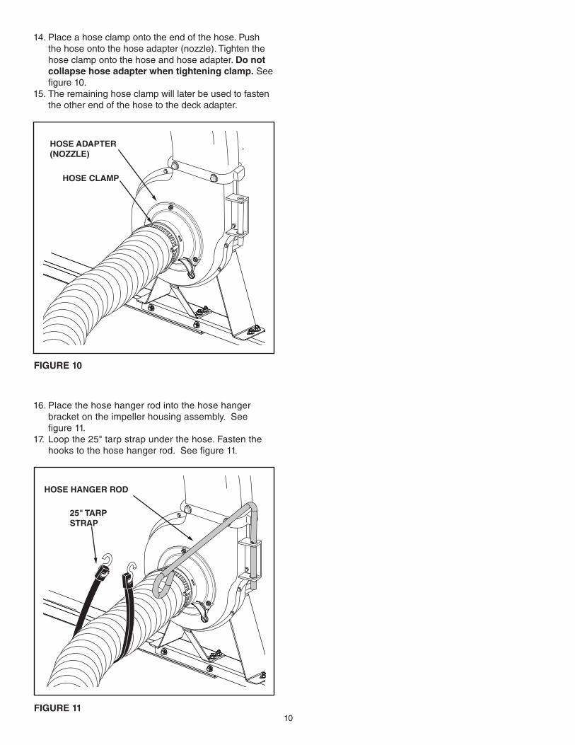
16. Place the hose hanger rod into the hose hanger bracket on the impeller housing assembly. See figure 11.
17. Loop the 25" tarp strap under the hose. Fasten the hooks to the hose hanger rod. See figure 11.
FIGURE 11
14. Place a hose clamp onto the end of the hose. Push the hose onto the hose adapter (nozzle). Tighten the hose clamp onto the hose and hose adapter. Do not collapsehoseadapterwhentighteningclamp. See figure 10.
15. The remaining hose clamp will later be used to fasten the other end of the hose to the deck adapter.
FIGURE 10
HOSE CLAMP
HOSE ADAPTER(NOZZLE)
25" TARPSTRAP
HOSE HANGER ROD

11
ASSEMBLINGTHEDECKADAPTER(#62468)TO THE MOWER DECK
ContentsofHardwarePackforDeckAdapter:
NOTE: Not all of the hardware will be used for any one particular fit up.
FIGURE 13
FIGURE 12
1/4" DOWNKeep cut-off as close to the top edge as possible.
IMPORTANT:
1/2" FROM FRONT
I
A B C
E
D
HG
F
NOT SHOWN FULL SIZE
SHOWN FULL SIZE
BEFOREPROCEEDING, look in the fold-out sheets to find the template for your mower deck. If written instructions are printed on the template, follow those instructions instead of the instructions in this manual.
STOP
CAUTION: Mower deflector must be replacedwhenVacSystemdeckadapteris removed. Do Not operate mower unless adapter or deflector is in place and properly mounted.
1. Identify and cut out the template for your brandandsize mower deck. If there is no template included for your deck size, you can make your own template by marking around a piece of cardboard held against the edge of the deck's discharge opening.
2. FOLLOW THE INSTRUCTIONS PRINTED ON THE TEMPLATE. If there are no instructions, use the following instructions as a general guide.
3. Tape the template to the face of the adapter, about 1/2" from front and 1/4" down from top for deeper
decks. For shallow decks, position template low enough that adapter will not extend below bottom of deck. Mark outline of template on face of adapter using white crayon, nail or scriber. Drill a starting hole inside the outline, then use a saber saw or key hole saw to cut out the opening. See figure 13.
PERFORM THIS STEP ONLY IF NECESSARY.4. Remove the mower discharge deflector from your
mower deck if necessary to attach deck adapter. Save the deflector and hardware for remounting deflector.
REF. PART NO. QTY. DESCRIPTIONA 43840 2 Hex Bolt, 5/16" x 1-1/4"B 43661 4 Hex Bolt, 1/4" x 1"C 43080 2 Carriage Bolt, 5/16" x 3/4"D 47810 3 Hex Nylock Nut, 5/16"E 47189 5 Hex Nylock Nut, 1/4"F 1543-69 5 Nylon WasherG 23826 1 Angle BracketH 23827 1 Mounting BracketI 23825 1 Mounting Strap
Need more help cutting out and assembling the deck adapter?Visityoutube.com/c/agrifab for product assembly instructions.
12
FIGURE 14
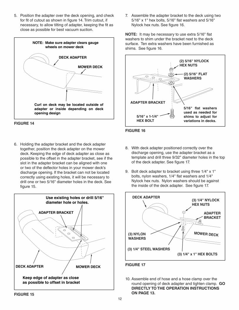
6. Holding the adapter bracket and the deck adapter together, position the deck adapter on the mower deck. Keeping the edge of deck adapter as close as possible to the offset in the adapter bracket, see if the slot in the adapter bracket can be aligned with one or two of the deflector holes in your mower deck's discharge opening. If the bracket can not be located correctly using existing holes, it will be necessary to drill one or two 5/16" diameter holes in the deck. See figure 15.
5. Position the adapter over the deck opening, and check for fit of cutout as shown in figure 14. Trim cutout, if necessary, to allow tilting of adapter, keeping the fit as close as possible for best vacuum suction.
7. Assemble the adapter bracket to the deck using two 5/16" x 1" hex bolts, 5/16" flat washers and 5/16" Nylock hex nuts. See figure 16.
NOTE: It may be necessary to use extra 5/16" flat washers to shim under the bracket next to the deck surface. Ten extra washers have been furnished as shims. See figure 16.
FIGURE 16
FIGURE 17
10. Assemble end of hose and a hose clamp over the round opening of deck adapter and tighten clamp. GO DIRECTLY TO THE OPERATION INSTRUCTIONS ON PAGE 13.
8. With deck adapter positioned correctly over the discharge opening, use the adapter bracket as a template and drill three 9/32" diameter holes in the top of the deck adapter. See figure 17.
9. Bolt deck adapter to bracket using three 1/4" x 1" bolts, nylon washers, 1/4" flat washers and 1/4" Nylock hex nuts. Nylon washers should be against the inside of the deck adapter. See figure 17.
FIGURE 15
MOWER DECK
DECK ADAPTER
NOTE: Make sure adapter clears gauge wheels on mower deck
Curl on deck may be located outside of adapter or inside depending on deck opening design
DECK ADAPTER MOWER DECK
ADAPTER BRACKET
Keep edge of adapter as close as possible to offset in bracket
Use existing holes or drill 5/16" diameter hole or holes.
(3) 1/4" NYLOCK HEX NUTS
(3) NYLON WASHERS
(3) 1/4" STEEL WASHERS (3) 1/4" x 1" HEX BOLTS
ADAPTER BRACKET
MOWER DECK
DECK ADAPTER
ADAPTER BRACKET
5/16" flat washers used as needed for shims to adjust for variations in decks.
(2) 5/16" NYLOCKHEX NUTS
5/16" x 1-1/4"HEX BOLT
(2) 5/16" FLATWASHERS
13
FIGURE 18
OPERATION
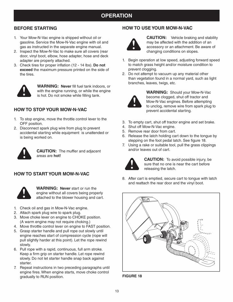
8. After cart is emptied, secure cart to tongue with latch and reattach the rear door and the vinyl boot.
HOW TO USE YOUR MOW-N-VACBEFORE STARTING
1. YourMow-N-Vacengineisshippedwithoutoilorgasoline.ServicetheMow-N-Vacenginewithoilandgas as instructed in the separate engine manual.
2. InspecttheMow-N-Vactomakesureallcovers(reardoor, vinyl boot, elbow, hose adapter, hose and deck adapter are properly attached.
3. Check tires for proper inflation (12 - 14 lbs). Do not exceed the maximum pressure printed on the side of the tires.
WARNING: Never fill fuel tank indoors, or with the engine running, or while the engine is hot. Do not smoke while filling tank.
HOW TO STOP YOUR MOW-N-VAC
1. To stop engine, move the throttle control lever to the OFF position.
2. Disconnect spark plug wire from plug to prevent accidental starting while equipment is unattended or is being worked on.
CAUTION: The muffler and adjacent areas are hot!
HOW TO START YOUR MOW-N-VAC
1. CheckoilandgasinMow-N-Vacengine.2. Attach spark plug wire to spark plug.3. Move choke lever on engine to CHOKE position. (A warm engine may not require choking.)4. Move throttle control lever on engine to FAST position.5. Grasp starter handle and pull rope out slowly until
engine reaches start of compression cycle (rope will pull slightly harder at this point). Let the rope rewind slowly.
6. Pull rope with a rapid, continuous, full arm stroke. Keep a firm grip on starter handle. Let rope rewind slowly. Do not let starter handle snap back against starter.
7. Repeat instructions in two preceding paragraphs until engine fires. When engine starts, move choke control gradually to RUN position.
WARNING: Never start or run the engine without all covers being properly attached to the blower housing and cart.
CAUTION: Vehiclebrakingandstabilitymay be affected with the addition of an accessory or an attachment. Be aware of changing conditions on slopes.
1. Begin operation at low speed, adjusting forward speed to match grass height and/or moisture condition to prevent clogging.
2. Do not attempt to vacuum up any material other than vegetation found in a normal yard, such as light branches, leaves, twigs, etc.
3. To empty cart, shut off tractor engine and set brake. 4. ShutoffMow-N-Vacengine.5. Remove rear door from cart.6. Release the latch holding cart down to the tongue by
stepping on the foot pedal latch. See figure 18.7. Using a rake or suitable tool, pull the grass clippings
and/or leaves out of cart.
WARNING: ShouldyourMow-N-Vacbecome clogged, shut off tractor and Mow-N-Vacengines.Beforeattemptingto unclog, remove wire from spark plug to prevent accidental starting.
CAUTION: To avoid possible injury, be sure that no one is near the cart before releasing the latch.
14
MAINTENANCE
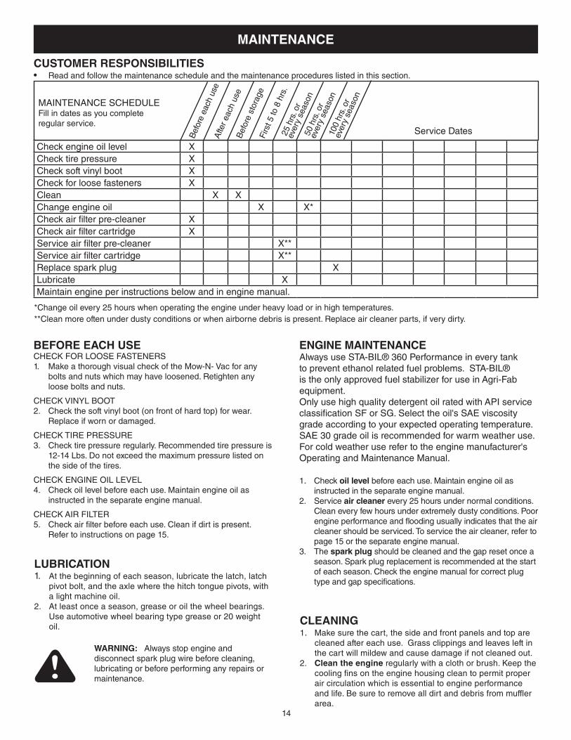
CUSTOMER RESPONSIBILITIES• Read and follow the maintenance schedule and the maintenance procedures listed in this section.
BEFORE EACH USECHECK FOR LOOSE FASTENERS1. MakeathoroughvisualcheckoftheMow-N-Vacforany
bolts and nuts which may have loosened. Retighten any loose bolts and nuts.
CHECKVINYLBOOT2. Check the soft vinyl boot (on front of hard top) for wear.
Replace if worn or damaged.
CHECK TIRE PRESSURE3. Check tire pressure regularly. Recommended tire pressure is
12-14 Lbs. Do not exceed the maximum pressure listed on the side of the tires.
CHECKENGINEOILLEVEL4. Check oil level before each use. Maintain engine oil as
instructed in the separate engine manual.
CHECK AIR FILTER5. Check air filter before each use. Clean if dirt is present.
Refer to instructions on page 15.
LUBRICATION1. At the beginning of each season, lubricate the latch, latch
pivot bolt, and the axle where the hitch tongue pivots, with a light machine oil.
2. At least once a season, grease or oil the wheel bearings. Use automotive wheel bearing type grease or 20 weight oil.
WARNING: Always stop engine and disconnect spark plug wire before cleaning, lubricating or before performing any repairs or maintenance.
ENGINE MAINTENANCEAlways use STA-BIL® 360 Performance in every tank to prevent ethanol related fuel problems. STA-BIL® is the only approved fuel stabilizer for use in Agri-Fab equipment.Only use high quality detergent oil rated with API service classification SF or SG. Select the oil's SAE viscosity grade according to your expected operating temperature. SAE 30 grade oil is recommended for warm weather use. For cold weather use refer to the engine manufacturer's Operating and Maintenance Manual.
1. Check oil level before each use. Maintain engine oil as instructed in the separate engine manual.
2. Service air cleaner every 25 hours under normal conditions. Clean every few hours under extremely dusty conditions. Poor engine performance and flooding usually indicates that the air cleaner should be serviced. To service the air cleaner, refer to page 15 or the separate engine manual.
3. The sparkplug should be cleaned and the gap reset once a season. Spark plug replacement is recommended at the start of each season. Check the engine manual for correct plug type and gap specifications.
CLEANING1. Make sure the cart, the side and front panels and top are
cleaned after each use. Grass clippings and leaves left in the cart will mildew and cause damage if not cleaned out.
2. Cleantheengine regularly with a cloth or brush. Keep the cooling fins on the engine housing clean to permit proper air circulation which is essential to engine performance and life. Be sure to remove all dirt and debris from muffler area.
MAINTENANCE SCHEDULEFill in dates as you complete regular service.
Bef
ore
each
use
Firs
t 5 to
8 h
rs.
25 h
rs. o
rev
ery
seas
on50
hrs
. or
ever
y se
ason
Afte
r eac
h us
e
Check engine oil level XCheck tire pressure XCheck soft vinyl boot XCheck for loose fasteners XClean X XChange engine oil X X*Check air filter pre-cleaner XCheck air filter cartridge XService air filter pre-cleaner X**Service air filter cartridge X**Replace spark plug XLubricate XMaintain engine per instructions below and in engine manual.
*Change oil every 25 hours when operating the engine under heavy load or in high temperatures.**Clean more often under dusty conditions or when airborne debris is present. Replace air cleaner parts, if very dirty.
Service DatesBef
ore
stor
age
100
hrs.
or
ever
y se
ason
15
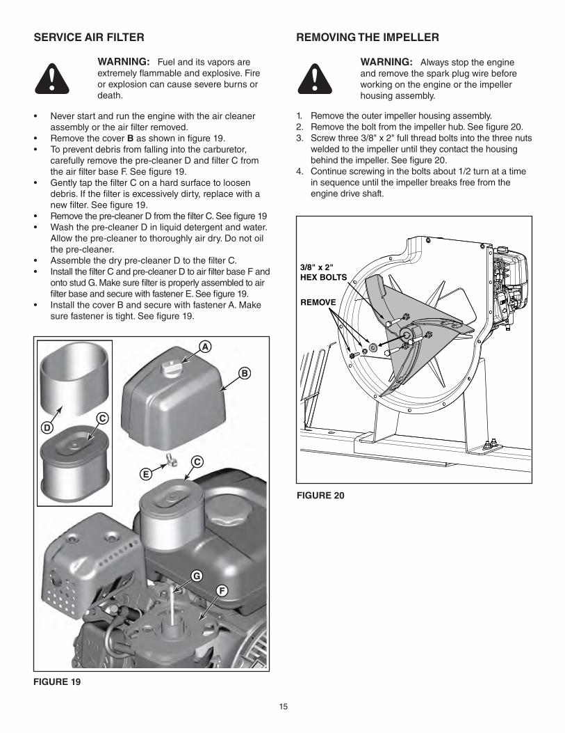
SERVICE AIR FILTER
• Neverstartandruntheenginewiththeaircleanerassembly or the air filter removed.
• RemovethecoverB as shown in figure 19.• Topreventdebrisfromfallingintothecarburetor,
carefully remove the pre-cleaner D and filter C from the air filter base F. See figure 19.
• GentlytapthefilterConahardsurfacetoloosendebris. If the filter is excessively dirty, replace with a new filter. See figure 19.
• Removethepre-cleanerDfromthefilterC.Seefigure19• Washthepre-cleanerDinliquiddetergentandwater.
Allow the pre-cleaner to thoroughly air dry. Do not oil the pre-cleaner.
• Assemblethedrypre-cleanerDtothefilterC.• InstallthefilterCandpre-cleanerDtoairfilterbaseFand
onto stud G. Make sure filter is properly assembled to air filter base and secure with fastener E. See figure 19.
• InstallthecoverBandsecurewithfastenerA.Makesure fastener is tight. See figure 19.
WARNING: Fuel and its vapors are extremely flammable and explosive. Fire or explosion can cause severe burns or death.
FIGURE 19
REMOVING THE IMPELLER
1. Remove the outer impeller housing assembly.2. Remove the bolt from the impeller hub. See figure 20.3. Screw three 3/8" x 2" full thread bolts into the three nuts
welded to the impeller until they contact the housing behind the impeller. See figure 20.
4. Continue screwing in the bolts about 1/2 turn at a time in sequence until the impeller breaks free from the engine drive shaft.
WARNING: Always stop the engine and remove the spark plug wire before working on the engine or the impeller housing assembly.
FIGURE 20
REMOVE
3/8" x 2"HEX BOLTS
16
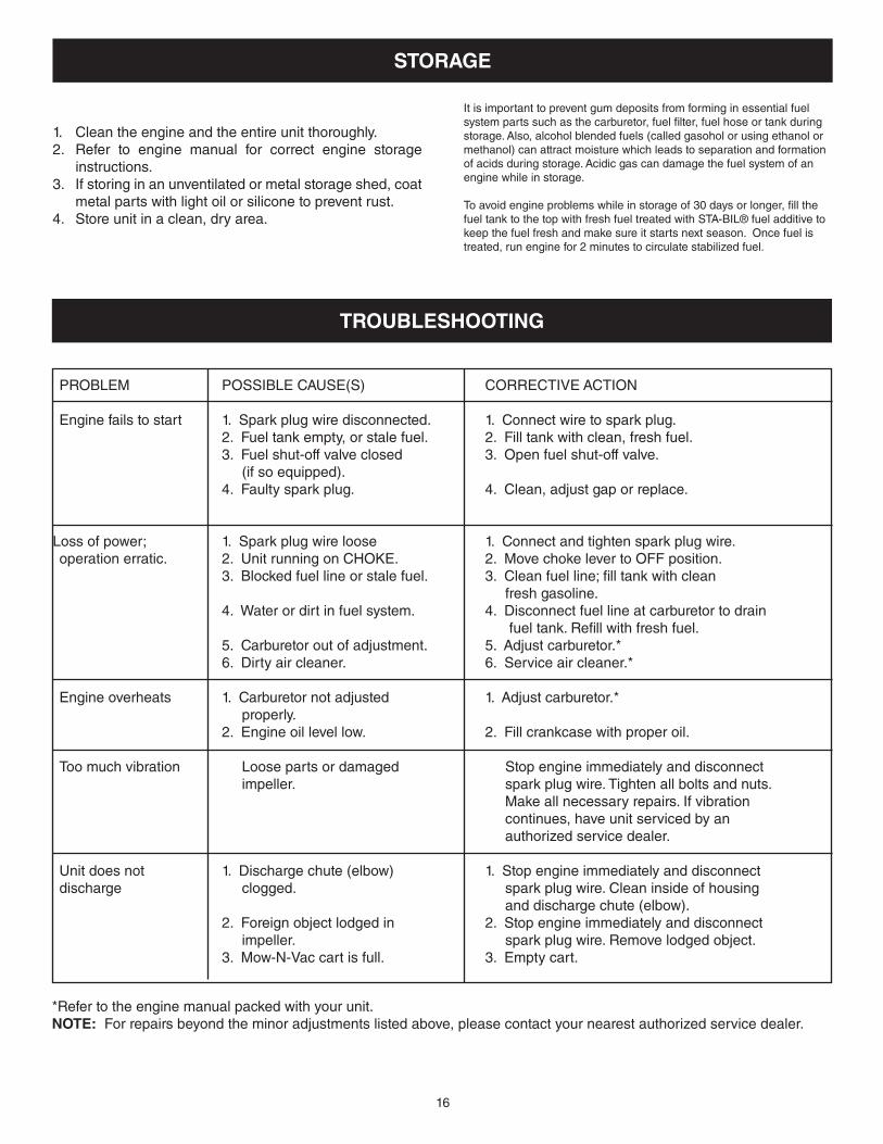
PROBLEM POSSIBLECAUSE(S) CORRECTIVEACTION
Engine fails to start 1. Spark plug wire disconnected. 1. Connect wire to spark plug. 2. Fuel tank empty, or stale fuel. 2. Fill tank with clean, fresh fuel. 3. Fuel shut-off valve closed 3. Open fuel shut-off valve. (if so equipped). 4. Faulty spark plug. 4. Clean, adjust gap or replace.
Loss of power; 1. Spark plug wire loose 1. Connect and tighten spark plug wire. operation erratic. 2. Unit running on CHOKE. 2. Move choke lever to OFF position. 3. Blocked fuel line or stale fuel. 3. Clean fuel line; fill tank with clean fresh gasoline. 4. Water or dirt in fuel system. 4. Disconnect fuel line at carburetor to drain fuel tank. Refill with fresh fuel. 5. Carburetor out of adjustment. 5. Adjust carburetor.* 6. Dirty air cleaner. 6. Service air cleaner.*
Engine overheats 1. Carburetor not adjusted 1. Adjust carburetor.* properly. 2. Engine oil level low. 2. Fill crankcase with proper oil.
Too much vibration Loose parts or damaged Stop engine immediately and disconnect impeller. spark plug wire. Tighten all bolts and nuts. Make all necessary repairs. If vibration continues, have unit serviced by an authorized service dealer.
Unit does not 1. Discharge chute (elbow) 1. Stop engine immediately and disconnect discharge clogged. spark plug wire. Clean inside of housing and discharge chute (elbow). 2. Foreign object lodged in 2. Stop engine immediately and disconnect impeller. spark plug wire. Remove lodged object. 3.Mow-N-Vaccartisfull. 3.Emptycart.
TROUBLESHOOTING
*Refer to the engine manual packed with your unit.NOTE: For repairs beyond the minor adjustments listed above, please contact your nearest authorized service dealer.
STORAGE
1. Clean the engine and the entire unit thoroughly.2. Refer to engine manual for correct engine storage
instructions.3. If storing in an unventilated or metal storage shed, coat
metal parts with light oil or silicone to prevent rust.4. Store unit in a clean, dry area.
It is important to prevent gum deposits from forming in essential fuel system parts such as the carburetor, fuel filter, fuel hose or tank during storage. Also, alcohol blended fuels (called gasohol or using ethanol or methanol) can attract moisture which leads to separation and formation of acids during storage. Acidic gas can damage the fuel system of an engine while in storage.
To avoid engine problems while in storage of 30 days or longer, fill the fuel tank to the top with fresh fuel treated with STA-BIL® fuel additive to keep the fuel fresh and make sure it starts next season. Once fuel is treated, run engine for 2 minutes to circulate stabilized fuel.
17
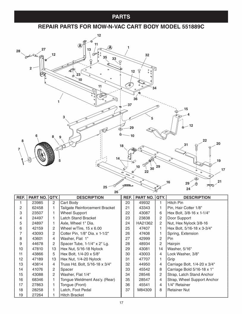
PARTS
REF. PART NO. QTY. DESCRIPTION1 23985 2 Cart Body2 62458 1 Tailgate Reinforcement Bracket3 23507 1 Wheel Support4 24497 1 Latch Stand Bracket5 24897 1 Axle, Wheel 1" Dia.6 42159 2 Wheel w/Tire, 15 x 6.007 43093 2 Cotter Pin, 1/8" Dia. x 1-1/2"8 43601 4 Washer, Flat 1"9 44678 2 Spacer Tube, 1-1/4" x 2" Lg.10 47810 13 Hex Nut, 5/16-18 Nylock11 43866 5 Hex Bolt, 1/4-20 x 5/8"12 47189 13 Hex Nut, 1/4-20 Nylock13 43814 4 Truss Hd. Bolt, 5/16-18 x 3/4"14 41076 2 Spacer15 43088 2 Washer, Flat 1/4"16 68346 1 Tongue Weldment Ass'y. (Rear)17 27863 1 Tongue (Front)18 28258 1 Latch, Foot Pedal19 27264 1 Hitch Bracket
REF. PART NO. QTY. DESCRIPTION20 49932 1 Hitch Pin 21 43343 1 Pin, Hair Cotter 1/8"22 43087 6 Hex Bolt, 3/8-16 x 1-1/4"23 23838 2 Door Support24 HA21362 2 Nut, Hex Nylock 3/8-1625 47407 1 Hex Bolt, 5/16-18 x 3-3/4"26 47408 1 Spring, Extension27 42999 2 Pin28 48934 2 Hairpin29 43081 14 Washer, 5/16"30 43003 4 Lock Washer, 3/8"31 47707 1 Grip32 44950 4 Carriage Bolt, 1/4-20 x 3/4"33 45542 8 Carriage Bold 5/16-18 x 1"34 28546 2 Strap, Latch Stand Anchor35 28547 4 Strap, Wheel Support Anchor36 45541 4 1/4" Retainer37 M84309 8 Retainer Nut
REPAIR PARTS FOR MOW-N-VAC CART BODY MODEL 551889C
11
32
4
1
2
11
1
3 5
A
5
868
7
9
12
12
12
12
3335
13
10
34
20
23
28 27A
16
17
18
19
21
22
22
242526
10
10
14
29
31
3029
29
1537
36
18
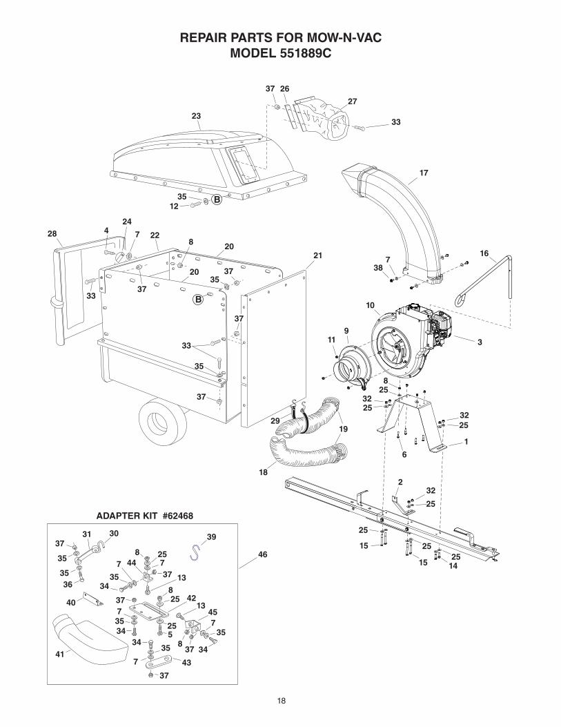
REPAIR PARTS FOR MOW-N-VACMODEL 551889C
26
33
27
23
424
78
1235
37
2120
37
33
35
37
16
17
19
18
29
738
22
2035
B
B
28
33
37
58
37
8
37
37
8
7
7 7
7
7
35
35
35
35
25
25
25
25
25
25
39
34
34
3413
41
4213
43
45
44
ADAPTER KIT #62468
37
46
1
2
6
8
9311
10
32
32
32
31 30
3635
35
37
40
34
25
25
25
25
15
15 14
37
19
the fastest way to purchase parts www.speedepart.com
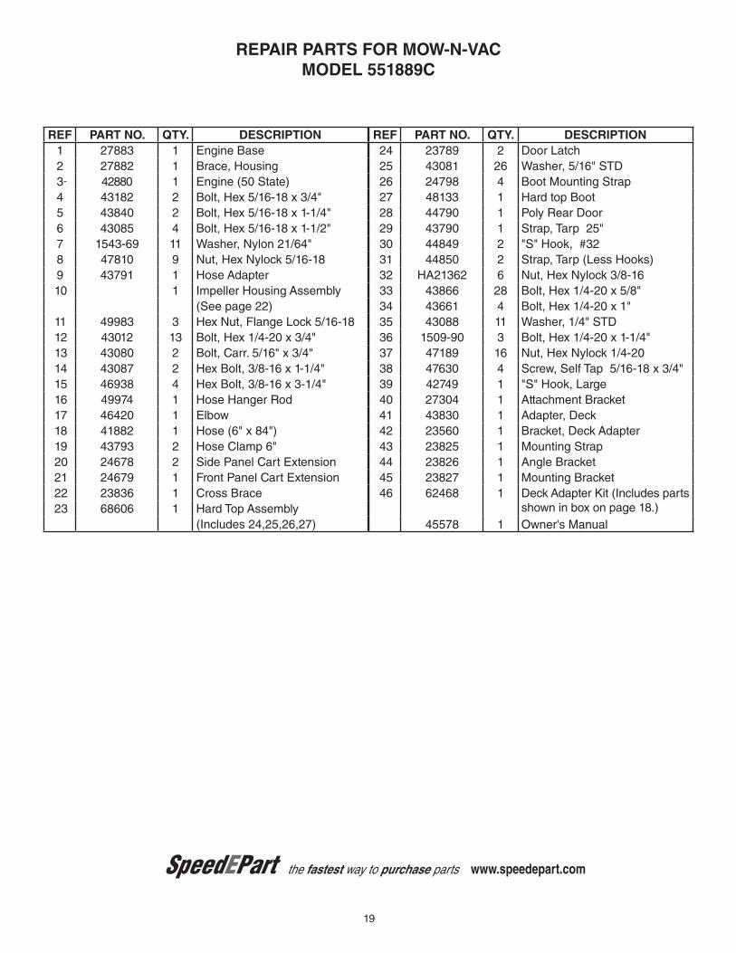
REPAIR PARTS FOR MOW-N-VACMODEL 551889C
REF PART NO. QTY. DESCRIPTION1 27883 1 Engine Base2 27882 1 Brace, Housing3 42880 1 Engine (50 State)4 43182 2 Bolt, Hex 5/16-18 x 3/4"5 43840 2 Bolt, Hex 5/16-18 x 1-1/4"6 43085 4 Bolt, Hex 5/16-18 x 1-1/2"7 1543-69 11 Washer, Nylon 21/64"8 47810 9 Nut, Hex Nylock 5/16-189 43791 1 Hose Adapter10 1 Impeller Housing Assembly
(See page 22)11 49983 3 Hex Nut, Flange Lock 5/16-1812 43012 13 Bolt, Hex 1/4-20 x 3/4"13 43080 2 Bolt, Carr. 5/16" x 3/4"14 43087 2 Hex Bolt, 3/8-16 x 1-1/4"15 46938 4 Hex Bolt, 3/8-16 x 3-1/4"16 49974 1 Hose Hanger Rod17 46420 1 Elbow18 41882 1 Hose (6" x 84")19 43793 2 Hose Clamp 6"20 24678 2 Side Panel Cart Extension21 24679 1 Front Panel Cart Extension22 23836 1 Cross Brace23 68606 1 Hard Top Assembly
(Includes 24,25,26,27)
REF PART NO. QTY. DESCRIPTION24 23789 2 Door Latch25 43081 26 Washer, 5/16" STD26 24798 4 Boot Mounting Strap27 48133 1 Hard top Boot28 44790 1 Poly Rear Door29 43790 1 Strap, Tarp 25"30 44849 2 "S" Hook, #3231 44850 2 Strap, Tarp (Less Hooks)32 HA21362 6 Nut, Hex Nylock 3/8-1633 43866 28 Bolt, Hex 1/4-20 x 5/8"34 43661 4 Bolt, Hex 1/4-20 x 1"35 43088 11 Washer, 1/4" STD36 1509-90 3 Bolt, Hex 1/4-20 x 1-1/4"37 47189 16 Nut, Hex Nylock 1/4-2038 47630 4 Screw, Self Tap 5/16-18 x 3/4"39 42749 1 "S" Hook, Large40 27304 1 Attachment Bracket41 43830 1 Adapter, Deck42 23560 1 Bracket, Deck Adapter43 23825 1 Mounting Strap44 23826 1 Angle Bracket45 23827 1 Mounting Bracket46 62468 1 Deck Adapter Kit (Includes parts
shown in box on page 18.)45578 1 Owner's Manual
20
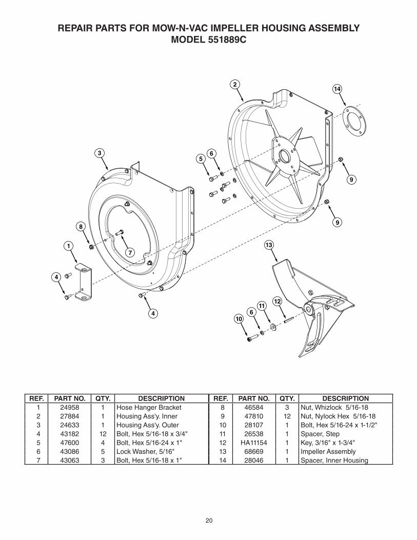
REPAIR PARTS FOR MOW-N-VAC IMPELLER HOUSING ASSEMBLYMODEL 551889C
REF. PART NO. QTY. DESCRIPTION1 24958 1 Hose Hanger Bracket2 27884 1 Housing Ass'y. Inner3 24633 1 Housing Ass'y. Outer4 43182 12 Bolt, Hex 5/16-18 x 3/4"5 47600 4 Bolt, Hex 5/16-24 x 1"6 43086 5 Lock Washer, 5/16"7 43063 3 Bolt, Hex 5/16-18 x 1"
REF. PART NO. QTY. DESCRIPTION8 46584 3 Nut, Whizlock 5/16-189 47810 12 Nut, Nylock Hex 5/16-1810 28107 1 Bolt, Hex 5/16-24 x 1-1/2"11 26538 1 Spacer, Step12 HA11154 1 Key, 3/16" x 1-3/4"13 68669 1 Impeller Assembly14 28046 1 Spacer, Inner Housing
1
4
35
2
6
14
4
9
9
713
611
12
10
8
21
A P
OW
ER
PO
LE
A C
OR
NE
R O
F A
BU
ILD
ING
OR
A F
EN
CE
PO
ST
FOLD
ALO
NG
DO
TTED
LINE
, RE
PR
ES
EN
TING
A 10 D
EG
RE
E S
LOP
E
SIG
HT
AN
D H
OL
D T
HIS
LE
VE
L W
ITH
A V
ER
TIC
AL
TR
EE
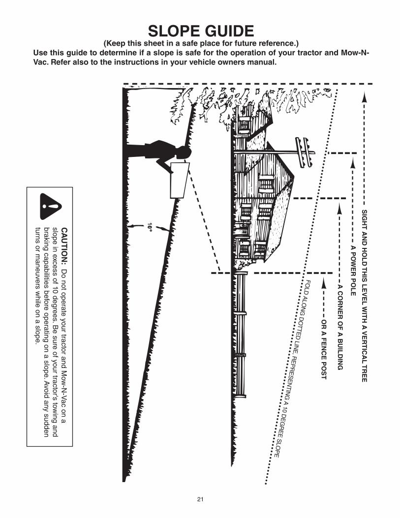
SLOPE GUIDE(Keepthissheetinasafeplaceforfuturereference.)
UsethisguidetodetermineifaslopeissafefortheoperationofyourtractorandMow-N-Vac.Referalsototheinstructionsinyourvehicleownersmanual.
CA
UT
ION
: DonotoperateyourtractorandM
ow-N-Vacona
slope in excess of 10 degrees. Be sure of your tractor's tow
ing and braking capabilities before operating on a slope. A
void any sudden turns or m
aneuvers while on a slope.

22

23

the fastest way to purchase parts www.speedepart.com
REPAIR PARTSAgri-Fab, Inc.
809 South Hamilton Sullivan, IL. 61951
217-728-8388www.agri-fab.com
© 2018 Agri-Fab, Inc.
This document (or manual) is protected under the U.S. Copyright Laws and the copyright laws of foreign countries, pursuant to the Universal Copyright Convention and the Berne convention. No part of this document may be reproduced or transmitted in any form or by any means, electronic or mechanical, including photocopying or recording, or by any information storage or retrieval system, without the express written permission of Agri-Fab, Inc. Unauthorized uses and/or reproductions of this manual will subject such unauthorized user to civil and criminal penalties as provided by the United States Copyright Laws.
PRINTED IN U.S.A.