Embed Size (px)
Citation preview
Temposonics®
Magnetostrictive, Absolute, Non-contact Linear-Position Sensors
MH-Series Model MH Mobile Hydraulic Sensor CAN Test KitCANopen, CAN Safety and CAN J1939 Outputs
SENSORS
®
Document Part Number551140 Revision B
Installation and User’s Manual
The Measurable Difference
1
TABLE OF CONTENTS
General InformationContact and support information ............................................ 1Related publications ............................................................... 1
1.0 MH-Series CAN Test Kit1.1 Kit contents .................................................................... 2
2.0 Installation2.1 Installing USB-CAN adapter drivers ................................ 22.2 Installing the CAN test software .......................................42.3 Connecting the USB-CAN adapter to the PC ................... 42.4 Connecting the sensor to the USB-CAN adapter ............. 5
2.4.1 Cable options for connecting the sensor ................... 52.4.2 Connecting the sensor .............................................. 5
2.5 Registering the software ................................................. 52.5.1 Obtaining the unlock code ........................................ 5
3.0 Operation3.1 Startup ............................................................................ 63.2 Familiarizing yourself with the GUI ................................. 63.3 Input sensor parameters ................................................. 7
3.3.1 Selecting the sensor protocol ................................... 73.3.2 Selecting the sensor baud rate ................................ 73.3.3 Input sensor node ID ................................................ 7
3.4 Sensor search ................................................................. 73.5 Start test ......................................................................... 83.6 Communication window ................................................ 8
3.6.1 Messages tab ........................................................... 83.6.2 Communications log tab .......................................... 8
3.7 Graphing window ............................................................ 93.7.1 Position/velocity selection ....................................... 93.7.2 Graphing window setup ............................................ 93.7.3 Reset graph settings ................................................. 9
3.8 Modifying sensor settings............................................... 93.8.1 To modify the parameters ....................................... 93.8.2 Changing the;sensor node ID ................................... 93.8.3 Changing the baud rate ........................................... 93.8.4 Reading the cycle time .......................................... 103.8.5 Changing the cycle time ......................................... 10
3.9 Status bits ......................................................................103.10 Stop test ......................................................................10
MH-Series CAN Test Kit, CAN J1939, CANOpen and CAN SafetyTable of Contents, Contact Information
General Contact Information:Tel.: (919) 677-0100 Fax: (919) 677-2343E-mail: [email protected]://www.mtssensors.com
Mailing and Shipping Address: MTS Systems CorporationSensors Division3001 Sheldon Dr. Cary, North Carolina27513 USA
Customer Service:Tel.: (800) 633-7609Fax: (800) 498-4442E-mail: [email protected]
Technical Support and Applications:24 Hour Emergency Technical SupportTel.: 1 (800) 633-7609E-mail: [email protected]
Office Hours (EST):Monday - Thursday: 8:00 a.m. to 5:00 p.m.Friday: 8:00 a.m. to 4:00 p.m.
Remittance Address:MTS Systems CorporationSensors DivisionNW 5872 P.O. Box 1450Minneapolis, MN USA55486-5872
Quote and Contract Terms & Conditions:The parties expressly agree that the purchase and use of Material and/or Services from MTS Sensors Division are subject to MTS’ Terms and Conditions, in effect as of the date of this document, which are located at http://www.mtssensors.com/about/terms-and-conditions/index.html and are incorporated by reference into this and any ensuing contract. Printed Terms and Conditions can be provided upon request by E-mailing [email protected].
Related Publications:
MH-Series CAN Test kit Interface Data Sheet MTS part no. 551141 is available in PDF format at http://www.mtssensors.com.
MTS Sensors
Temposonics® Linear-Position Sensors - MH Series CAN Test Kit User Manual, CANOpen, CAN J1939 and CAN Safety Outputs Document Part No.: 551140 Revision B, 10/13
1.0 MH-SERIES CAN TEST KIT
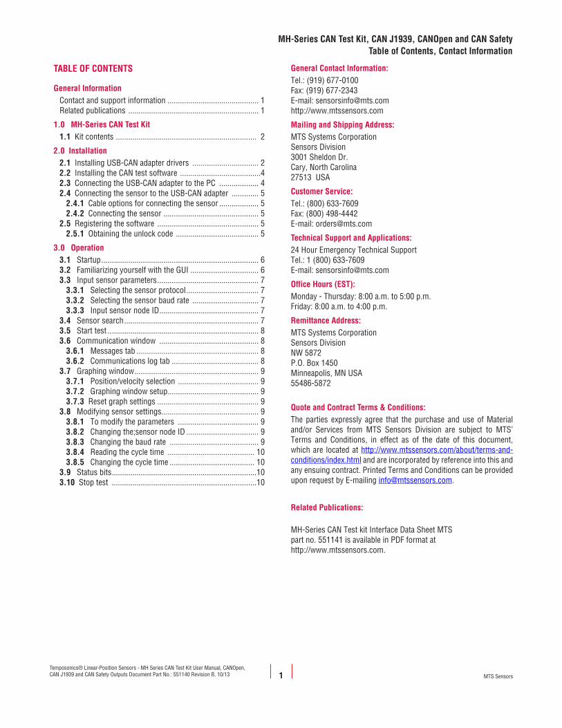
1.1 Kit contentsThe MH-Series CAN Test Kit includes:
• USB CAN adapter kit: • USB-CAN adapter• Utility CD (inclusive manual and drivers)
• M12 test cable with DB9 connector• Pigtailed test cable with DB9 connector• Multi-plug 12 Vdc power supply cable with power plug adapters• MTS CAN Test Interface installation CD• Carrying case• CAN Test Interface Installation Manual/User’s Guide
2.0 INSTALLATION
2.1 Installing USB-CAN adapter drivers software
Note:
This software must be installed on a PC using Windows 2000 or higher.
1. Insert the ‘USB-CAN Adapter Utility CD’ into the CD drive.2. Close the CD drive and wait for the installation program to
begin.
3.
Notes:
If the installation program does not start automatically, use the Windows explore function and browse to the appropriate drive and path of the USB-CAN adapter Utility drivers directory, then double-click ‘Setup.exe’ to start the installation. Wait for the prompt to disconnect all USB-CAN adapters.
The ‘Welcome Screen/Language Select’ window opens.
4. Select the desired language button to continue.
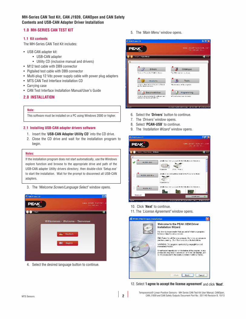
5. The ‘Main Menu’ window opens.
6. Select the ‘Drivers’ button to continue.7. The ‘Drivers’ window opens.8. Select ‘PCAN-USB’ to continue.9. The ‘Installation Wizard’ window opens.
10. Click ‘Next’ to continue.11. The ‘License Agreement’ window opens.
12. Select ‘I agree to accept the license agreement’ and click ‘Next’.
MH-Series CAN Test Kit, CAN J1939, CANOpen and CAN SafetyContents and USB-CAN Adapter Driver Installation
2MTS Sensors
Temposonics® Linear-Position Sensors - MH Series CAN Test Kit User Manual, CANOpen, CAN J1939 and CAN Safety Outputs Document Part No.: 551140 Revision B, 10/13
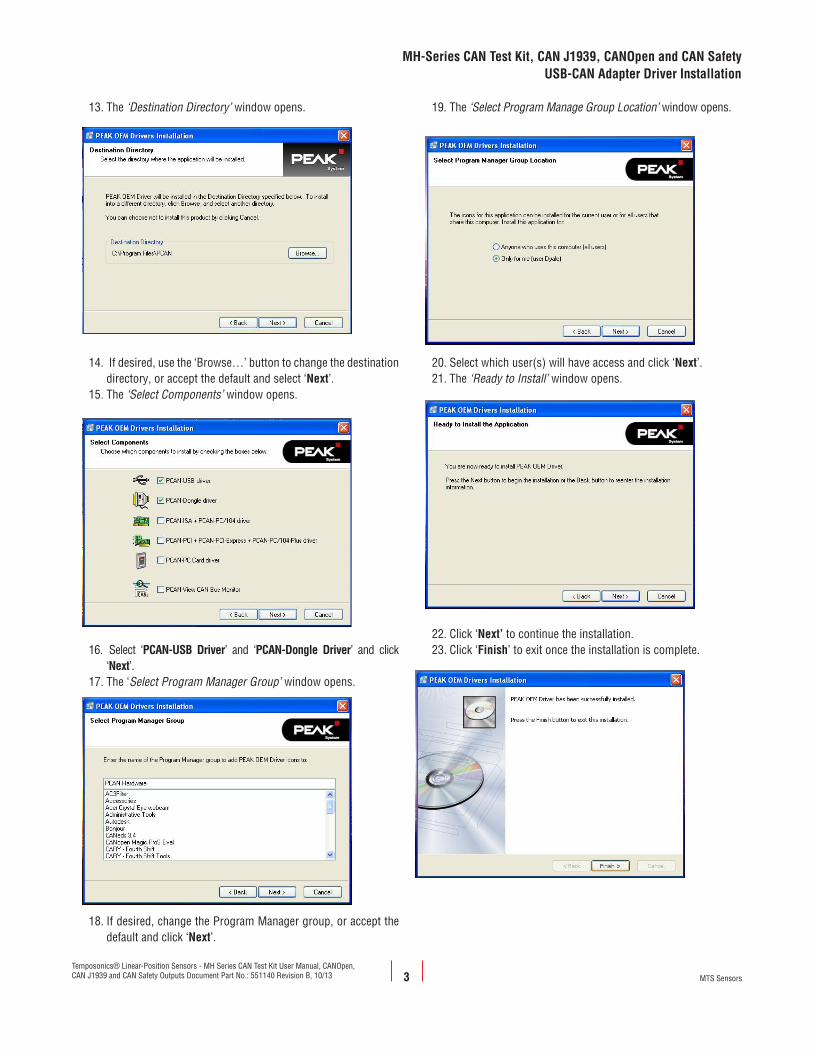
13. The ‘Destination Directory’ window opens.
14. If desired, use the ‘Browse…’ button to change the destination directory, or accept the default and select ‘Next’.
15. The ‘Select Components’ window opens.
16. Select ‘PCAN-USB Driver’ and ‘PCAN-Dongle Driver’ and click ‘Next’.
17. The ‘Select Program Manager Group’ window opens.
18. If desired, change the Program Manager group, or accept the default and click ‘Next’.
19. The ‘Select Program Manage Group Location’ window opens.
20. Select which user(s) will have access and click ‘Next’.21. The ‘Ready to Install’ window opens.
22. Click ‘Next’ to continue the installation.23. Click ‘Finish’ to exit once the installation is complete.
3
MH-Series CAN Test Kit, CAN J1939, CANOpen and CAN SafetyUSB-CAN Adapter Driver Installation
MTS Sensors
Temposonics® Linear-Position Sensors - MH Series CAN Test Kit User Manual, CANOpen, CAN J1939 and CAN Safety Outputs Document Part No.: 551140 Revision B, 10/13
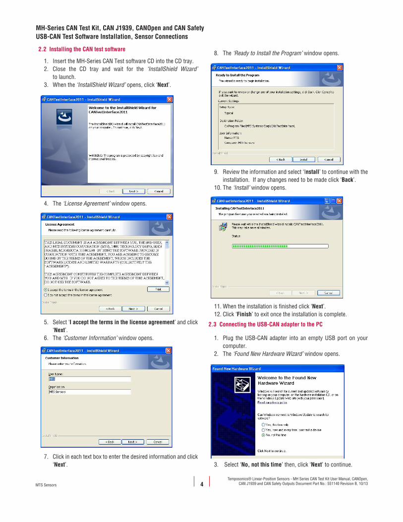
2.2 Installing the CAN test software
1. Insert the MH-Series CAN Test software CD into the CD tray.2. Close the CD tray and wait for the ‘InstallShield Wizard’
to launch.3. When the ‘InstallShield Wizard’ opens, click ‘Next’.
4. The ‘License Agreement’ window opens.
5. Select ‘I accept the terms in the license agreement’ and click ‘Next’.
6. The ‘Customer Information’ window opens.
7. Click in each text box to enter the desired information and click ‘Next’.
8. The ‘Ready to Install the Program’ window opens.
9. Review the information and select ‘Install’ to continue with the installation. If any changes need to be made click ‘Back’.
10. The ‘Install’ window opens.
11. When the installation is finished click ‘Next’.12. Click ‘Finish’ to exit once the installation is complete.
2.3 Connecting the USB-CAN adapter to the PC
1. Plug the USB-CAN adapter into an empty USB port on your computer.
2. The ‘Found New Hardware Wizard’ window opens.
3. Select ‘No, not this time’ then, click ‘Next’ to continue.
MH-Series CAN Test Kit, CAN J1939, CANOpen and CAN SafetyUSB-CAN Test Software Installation, Sensor Connections
4MTS Sensors
Temposonics® Linear-Position Sensors - MH Series CAN Test Kit User Manual, CANOpen, CAN J1939 and CAN Safety Outputs Document Part No.: 551140 Revision B, 10/13
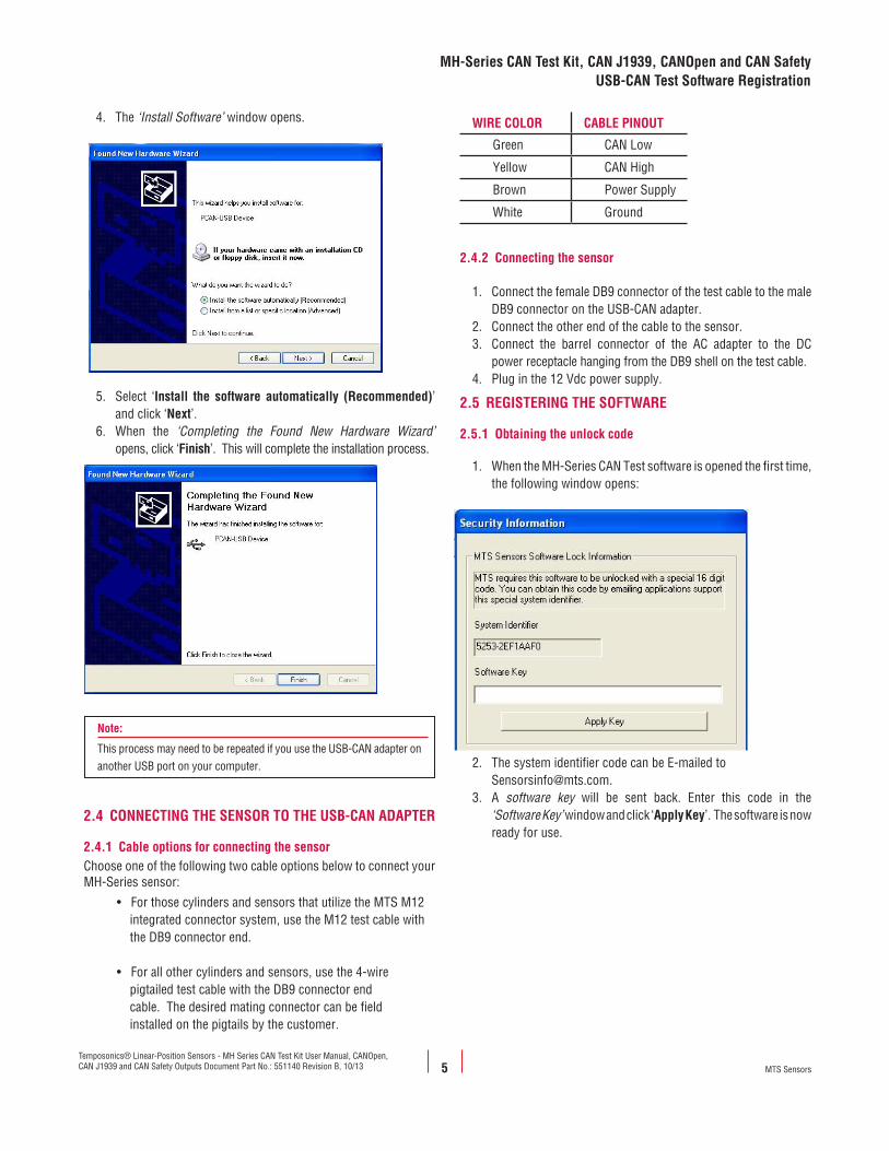
4. The ‘Install Software’ window opens.
5. Select ‘Install the software automatically (Recommended)’ and click ‘Next’.
6. When the ‘Completing the Found New Hardware Wizard’ opens, click ‘Finish’. This will complete the installation process.
Note:
This process may need to be repeated if you use the USB-CAN adapter on another USB port on your computer.
2.4 CONNECTING THE SENSOR TO THE USB-CAN ADAPTER
2.4.1 Cable options for connecting the sensorChoose one of the following two cable options below to connect your MH-Series sensor:
• For those cylinders and sensors that utilize the MTS M12 integrated connector system, use the M12 test cable with the DB9 connector end.
• For all other cylinders and sensors, use the 4-wire pigtailed test cable with the DB9 connector end cable. The desired mating connector can be field installed on the pigtails by the customer.
WIRE COLOR CABLE PINOUT
Green CAN Low
Yellow CAN High
Brown Power Supply
White Ground
2.4.2 Connecting the sensor
1. Connect the female DB9 connector of the test cable to the male DB9 connector on the USB-CAN adapter.
2. Connect the other end of the cable to the sensor.3. Connect the barrel connector of the AC adapter to the DC
power receptacle hanging from the DB9 shell on the test cable.4. Plug in the 12 Vdc power supply.
2.5 REGISTERING THE SOFTWARE
2.5.1 Obtaining the unlock code
1. When the MH-Series CAN Test software is opened the first time, the following window opens:
2. The system identifier code can be E-mailed to [email protected].
3. A software key will be sent back. Enter this code in the ‘Software Key’ window and click ‘Apply Key’. The software is now ready for use.
5
MH-Series CAN Test Kit, CAN J1939, CANOpen and CAN SafetyUSB-CAN Test Software Registration
MTS Sensors
Temposonics® Linear-Position Sensors - MH Series CAN Test Kit User Manual, CANOpen, CAN J1939 and CAN Safety Outputs Document Part No.: 551140 Revision B, 10/13
3.0 OPERATION
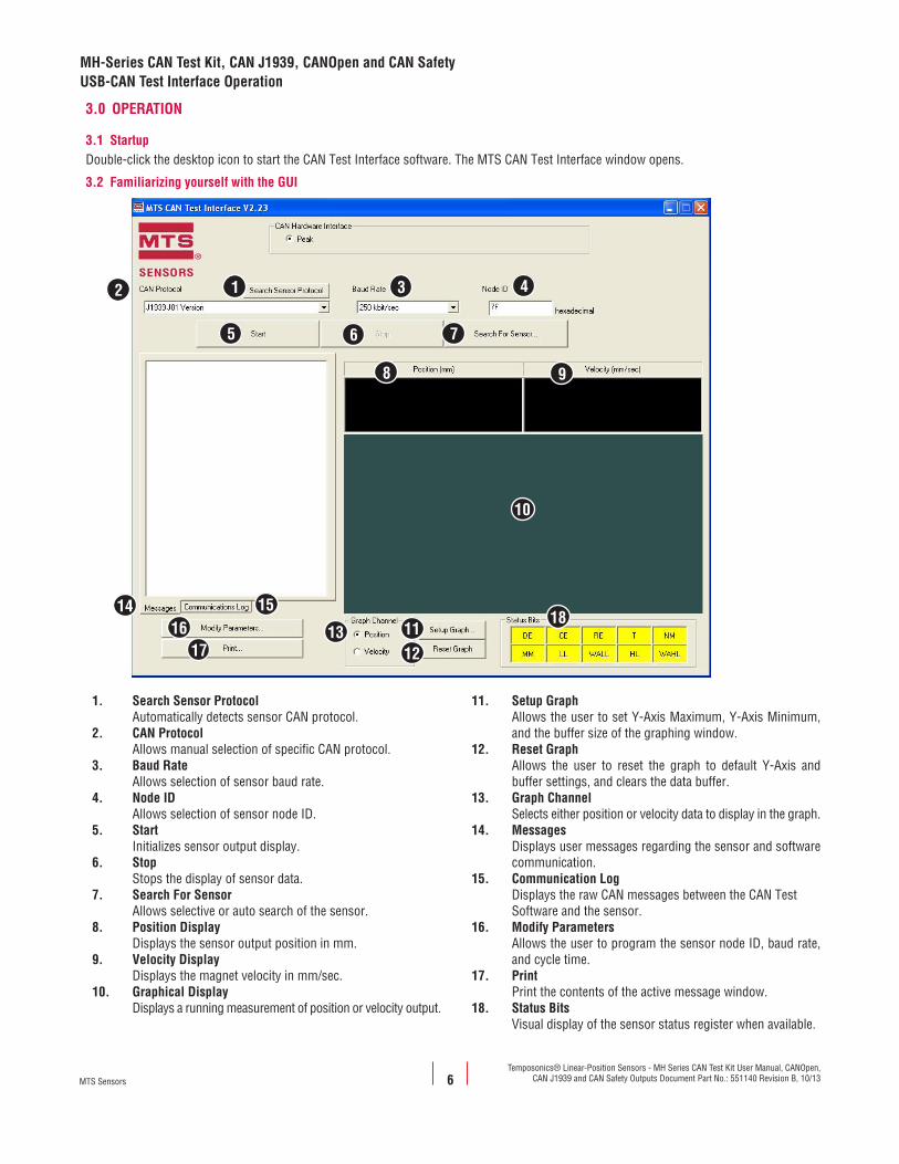
3.1 StartupDouble-click the desktop icon to start the CAN Test Interface software. The MTS CAN Test Interface window opens.
3.2 Familiarizing yourself with the GUI
MH-Series CAN Test Kit, CAN J1939, CANOpen and CAN SafetyUSB-CAN Test Interface Operation
6
12
5 6 7
3 4
8 9
14 15
1716 11
1213
18
1. Search Sensor Protocol Automatically detects sensor CAN protocol.2. CAN Protocol Allows manual selection of specific CAN protocol.3. Baud Rate Allows selection of sensor baud rate.4. Node ID Allows selection of sensor node ID.5. Start Initializes sensor output display.6. Stop Stops the display of sensor data.7. Search For Sensor Allows selective or auto search of the sensor.8. Position Display Displays the sensor output position in mm.9. Velocity Display Displays the magnet velocity in mm/sec.10. Graphical Display Displays a running measurement of position or velocity output.
11. Setup Graph Allows the user to set Y-Axis Maximum, Y-Axis Minimum, and the buffer size of the graphing window.12. Reset Graph Allows the user to reset the graph to default Y-Axis and buffer settings, and clears the data buffer.13. Graph Channel Selects either position or velocity data to display in the graph.14. Messages Displays user messages regarding the sensor and software communication.15. Communication Log Displays the raw CAN messages between the CAN Test Software and the sensor.16. Modify Parameters Allows the user to program the sensor node ID, baud rate, and cycle time.17. Print Print the contents of the active message window.18. Status Bits Visual display of the sensor status register when available.
10
MTS Sensors
Temposonics® Linear-Position Sensors - MH Series CAN Test Kit User Manual, CANOpen, CAN J1939 and CAN Safety Outputs Document Part No.: 551140 Revision B, 10/13
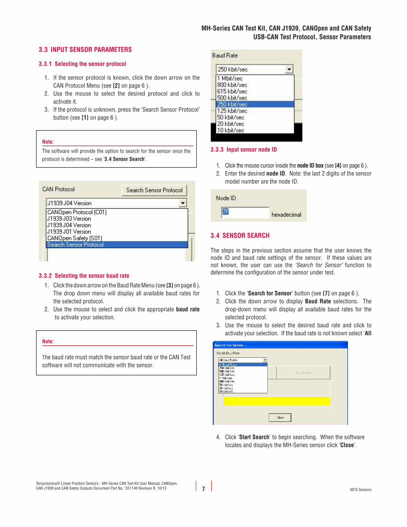
3.3 INPUT SENSOR PARAMETERS
3.3.1 Selecting the sensor protocol
1. If the sensor protocol is known, click the down arrow on the CAN Protocol Menu (see [2] on page 6 ).
2. Use the mouse to select the desired protocol and click to activate it.
3. If the protocol is unknown, press the ‘Search Sensor Protocol’ button (see [1] on page 6 ).
Note:
The software will provide the option to search for the sensor once the protocol is determined – see ‘3.4 Sensor Search’.
3.3.2 Selecting the sensor baud rate
1. Click the down arrow on the Baud Rate Menu (see [3] on page 6 ). The drop down menu will display all available baud rates for the selected protocol.
2. Use the mouse to select and click the appropriate baud rate to activate your selection.
Note:
The baud rate must match the sensor baud rate or the CAN Test software will not communicate with the sensor.
3.3.3 Input sensor node ID
1. Click the mouse cursor inside the node ID box (see [4] on page 6 ). 2. Enter the desired node ID. Note: the last 2 digits of the sensor
model number are the node ID.
3.4 SENSOR SEARCH
The steps in the previous section assume that the user knows the node ID and baud rate settings of the sensor. If these values are not known, the user can use the ‘Search for Sensor’ function to determine the configuration of the sensor under test.
1. Click the ‘Search for Sensor’ button (see [7] on page 6 ). 2. Click the down arrow to display Baud Rate selections. The
drop-down menu will display all available baud rates for the selected protocol.
3. Use the mouse to select the desired baud rate and click to activate your selection. If the baud rate is not known select ‘All
.Baud Rates’.
4. Click ‘Start Search’ to begin searching. When the software locates and displays the MH-Series sensor click ‘Close’.
7
MH-Series CAN Test Kit, CAN J1939, CANOpen and CAN SafetyUSB-CAN Test Protocol, Sensor Parameters
MTS Sensors
Temposonics® Linear-Position Sensors - MH Series CAN Test Kit User Manual, CANOpen, CAN J1939 and CAN Safety Outputs Document Part No.: 551140 Revision B, 10/13
8
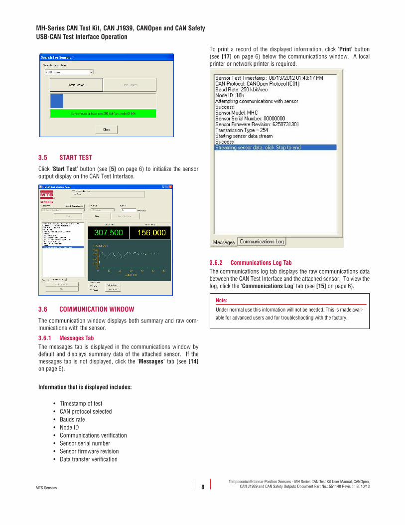
3.5 START TEST
Click ‘Start Test’ button (see [5] on page 6) to initialize the sensor output display on the CAN Test Interface.
3.6 COMMUNICATION WINDOW
The communication window displays both summary and raw com-munications with the sensor.
3.6.1 Messages TabThe messages tab is displayed in the communications window by default and displays summary data of the attached sensor. If the messages tab is not displayed, click the ‘Messages’ tab (see [14] on page 6).
Information that is displayed includes:
• Timestamp of test• CAN protocol selected• Bauds rate• Node ID• Communications verification• Sensor serial number• Sensor firmware revision• Data transfer verification
To print a record of the displayed information, click ‘Print’ button (see [17] on page 6) below the communications window. A local printer or network printer is required.
3.6.2 Communications Log TabThe communications log tab displays the raw communications data between the CAN Test Interface and the attached sensor. To view the log, click the ‘Communications Log’ tab (see [15] on page 6).
Note:
Under normal use this information will not be needed. This is made avail-able for advanced users and for troubleshooting with the factory.
MH-Series CAN Test Kit, CAN J1939, CANOpen and CAN SafetyUSB-CAN Test Interface Operation
MTS Sensors
Temposonics® Linear-Position Sensors - MH Series CAN Test Kit User Manual, CANOpen, CAN J1939 and CAN Safety Outputs Document Part No.: 551140 Revision B, 10/13
9
The ‘Print’ button can also be used to print a record of this screen.
3.7 GRAPHING WINDOW
The ‘graphing’ window (see [10] on page 6) displays a rolling display of the sensor output data of the position display (see [8] on page 6) or the velocity display (see [9] on page 6).
3.7.1 Position/Velocity SelectionTo view the graphical representation of the sensor output click the ‘Position’ or ‘Velocity’ radio button in the Graph Channel box (see [13] on page 6).
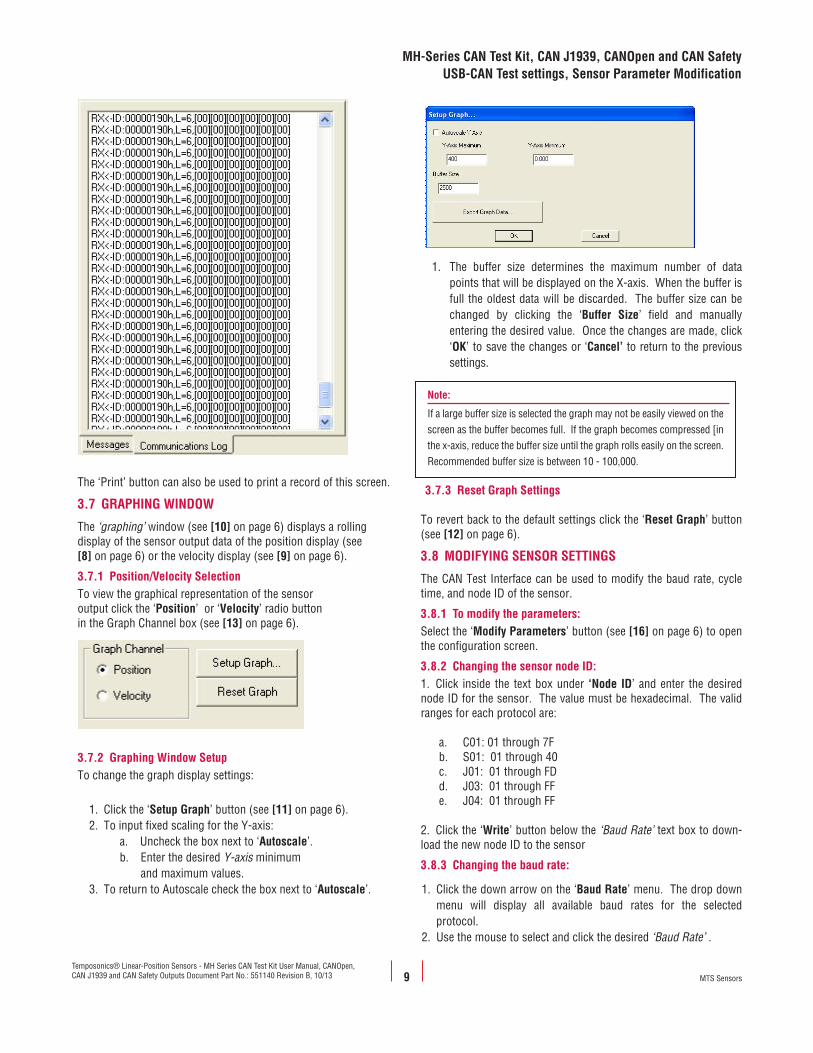
3.7.2 Graphing Window SetupTo change the graph display settings:
1. Click the ‘Setup Graph’ button (see [11] on page 6).2. To input fixed scaling for the Y-axis:
a. Uncheck the box next to ‘Autoscale’. b. Enter the desired Y-axis minimum and maximum values.
3. To return to Autoscale check the box next to ‘Autoscale’.
1. The buffer size determines the maximum number of data points that will be displayed on the X-axis. When the buffer is full the oldest data will be discarded. The buffer size can be changed by clicking the ‘Buffer Size’ field and manually entering the desired value. Once the changes are made, click ‘OK’ to save the changes or ‘Cancel’ to return to the previous settings.
Note:
If a large buffer size is selected the graph may not be easily viewed on the screen as the buffer becomes full. If the graph becomes compressed [in the x-axis, reduce the buffer size until the graph rolls easily on the screen. Recommended buffer size is between 10 - 100,000.
3.7.3 Reset Graph Settings
To revert back to the default settings click the ‘Reset Graph’ button (see [12] on page 6).
3.8 MODIFYING SENSOR SETTINGS
The CAN Test Interface can be used to modify the baud rate, cycle time, and node ID of the sensor.
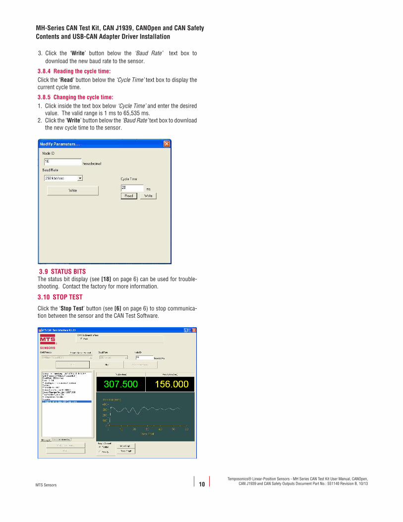
3.8.1 To modify the parameters:Select the ‘Modify Parameters’ button (see [16] on page 6) to open the configuration screen.
3.8.2 Changing the sensor node ID:1. Click inside the text box under ‘Node ID’ and enter the desired node ID for the sensor. The value must be hexadecimal. The valid ranges for each protocol are:
a. C01: 01 through 7Fb. S01: 01 through 40c. J01: 01 through FDd. J03: 01 through FFe. J04: 01 through FF
2. Click the ‘Write’ button below the ‘Baud Rate’ text box to down-load the new node ID to the sensor
3.8.3 Changing the baud rate:
1. Click the down arrow on the ‘Baud Rate’ menu. The drop down menu will display all available baud rates for the selected protocol.
2. Use the mouse to select and click the desired ‘Baud Rate’ .
MH-Series CAN Test Kit, CAN J1939, CANOpen and CAN SafetyUSB-CAN Test settings, Sensor Parameter Modification
MTS Sensors
Temposonics® Linear-Position Sensors - MH Series CAN Test Kit User Manual, CANOpen, CAN J1939 and CAN Safety Outputs Document Part No.: 551140 Revision B, 10/13
MH-Series CAN Test Kit, CAN J1939, CANOpen and CAN SafetyContents and USB-CAN Adapter Driver Installation
10
3. Click the ‘Write’ button below the ‘Baud Rate’ text box to download the new baud rate to the sensor.
3.8.4 Reading the cycle time:Click the ‘Read’ button below the ‘Cycle Time’ text box to display the current cycle time.
3.8.5 Changing the cycle time:1. Click inside the text box below ‘Cycle Time’ and enter the desired value. The valid range is 1 ms to 65,535 ms.2. Click the ‘Write’ button below the ‘Baud Rate’ text box to download the new cycle time to the sensor.
3.9 STATUS BITSThe status bit display (see [18] on page 6) can be used for trouble-shooting. Contact the factory for more information.
3.10 STOP TEST
Click the ‘Stop Test’ button (see [6] on page 6) to stop communica-tion between the sensor and the CAN Test Software.
MTS Sensors
Temposonics® Linear-Position Sensors - MH Series CAN Test Kit User Manual, CANOpen, CAN J1939 and CAN Safety Outputs Document Part No.: 551140 Revision B, 10/13
MTS Systems CorporationSensors Division
3001 Sheldon DriveCary, North Carolina27513, USATel.: +1-800-633-7609Fax: +1-919-677-2343 +1-800-498-4442e-mail: [email protected]://www.mtssensors.com
MTS Sensor TechnologieGmbH & Co. KG
Auf dem Schüffel 9D - 58513 Lüdenscheid, GermanyTel.: +49-2351-9587-0Fax: +49-2351-56491e-mail: [email protected]://www.mtssensor.de
MTS Sensors TechnologyCorporation
737 Aihara-cho, Machida-shiTokyo 194-0211, JapanTel.: +81-42-775-3838Fax: +81-42-775-5516e-mail: [email protected]://www.mtssensor.co.jp
SENSORS
®
Document Part Number: 551140 Revision B, 10/13
MTS and Temposonics are registered trademarks of MTS Systems Corporation.All other trademarks are the property of their respective owners.
Printed in USA. Copyright © 2013 MTS Systems Corporation. All Rights Reserved in all media.