Embed Size (px)
Citation preview
7/23/2019 54458302 IBM 6400
http://slidepdf.com/reader/full/54458302-ibm-6400 1/349
Ethernet Interface
User’s Manual
6400i Line Matrix Printers
Form Number S544-5830-02
Copyright IBM Corp., 2003

7/23/2019 54458302 IBM 6400
http://slidepdf.com/reader/full/54458302-ibm-6400 2/349
7/23/2019 54458302 IBM 6400
http://slidepdf.com/reader/full/54458302-ibm-6400 3/349
S544-5830-02
Ethernet Interface
User’s Manual
6400i Line Matrix Printers
7/23/2019 54458302 IBM 6400
http://slidepdf.com/reader/full/54458302-ibm-6400 4/349
Third Edition (May 2003)
This edition replaces S544-5830-01.
Requests for IBM ® publications should be made to your IBMrepresentative or to the IBM branch office serving your locality. If yourequest publications from the address given below, your order will bedelayed because publications are not stocked here. Many of the IBMPrinting Systems Division publications are available from the web pagelisted below.
A Reader’s Comment form is provided at the back of this publication. Ifthe form has been removed, you can send comments by fax to1-800-524-1519 (USA only) or 1-303-924-6873; by E-mail [email protected]; or by mail to:
IBM Printing Systems DivisionDepartment H7FE Building 004MInformation DevelopmentPO Box 1900Boulder CO 80301-9191 USA
IBM may use or distribute whatever information you supply in any way itbelieves appropriate without incurring any oblication to you.
© Copyright International Business Machines Corporation 2003. Alrights reserved.
US Government Users Restricted Rights – Use, duplication or disclosurerestricted by GSA ADP Schedule Contract with IBM Corp.
Before using this information and the product it supports, read the information in “Notices”on page 315.
Note!
Visit our home page at: http://www.ibm.com/printersInternet
7/23/2019 54458302 IBM 6400
http://slidepdf.com/reader/full/54458302-ibm-6400 5/349
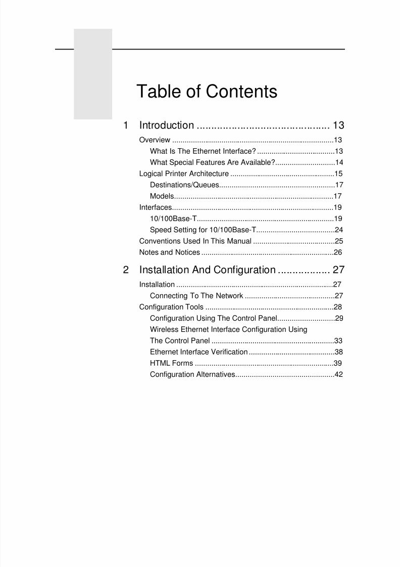
Table of Contents1 Introduction .............................................. 13
Overview ...............................................................................13
What Is The Ethernet Interface? ......................................13
What Special Features Are Available?.............................14
Logical Printer Architecture ...................................................15
Destinations/Queues........................................................17
Models..............................................................................17Interfaces...............................................................................19
10/100Base-T...................................................................19
Speed Setting for 10/100Base-T......................................24
Conventions Used In This Manual ........................................25
Notes and Notices .................................................................26
2 Installation And Configuration .................. 27Installation .............................................................................27
Connecting To The Network ............................................27Configuration Tools ...............................................................28
Configuration Using The Control Panel............................29
Wireless Ethernet Interface Configuration Using
The Control Panel ............................................................33
Ethernet Interface Verification ..........................................38
HTML Forms ....................................................................39
Configuration Alternatives................................................42
7/23/2019 54458302 IBM 6400
http://slidepdf.com/reader/full/54458302-ibm-6400 6/349
Table of Contents
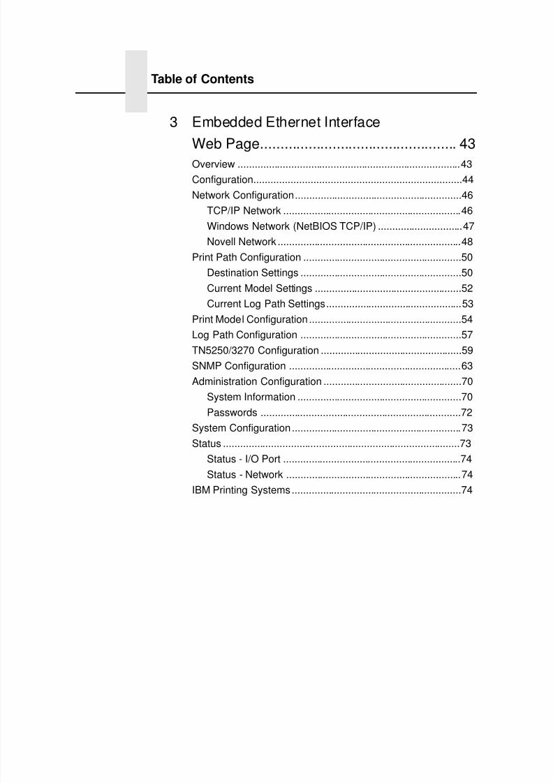
3 Embedded Ethernet Interface
Web Page................................................. 43Overview ...............................................................................43
Configuration.........................................................................44
Network Configuration...........................................................46
TCP/IP Network ...............................................................46
Windows Network (NetBIOS TCP/IP) ..............................47
Novell Network .................................................................48
Print Path Configuration ........................................................50
Destination Settings .........................................................50Current Model Settings ....................................................52
Current Log Path Settings................................................53
Print Model Configuration ......................................................54
Log Path Configuration .........................................................57
TN5250/3270 Configuration ..................................................59
SNMP Configuration .............................................................63
Administration Configuration .................................................70
System Information ..........................................................70
Passwords .......................................................................72System Configuration ............................................................73
Status ....................................................................................73
Status - I/O Port ...............................................................74
Status - Network ..............................................................74
IBM Printing Systems............................................................74
7/23/2019 54458302 IBM 6400
http://slidepdf.com/reader/full/54458302-ibm-6400 7/349
Table of Contents
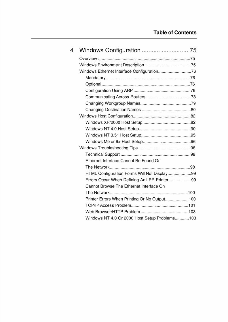
4 Windows Configuration ............................ 75Overview ...............................................................................75
Windows Environment Description........................................75
Windows Ethernet Interface Configuration............................76
Mandatory ........................................................................76
Optional............................................................................76
Configuration Using ARP .................................................76
Communicating Across Routers.......................................78
Changing Workgroup Names...........................................79
Changing Destination Names ..........................................80
Windows Host Configuration.................................................82
Windows XP/2000 Host Setup.........................................82
Windows NT 4.0 Host Setup............................................90
Windows NT 3.51 Host Setup..........................................95
Windows Me or 9x Host Setup.........................................96
Windows Troubleshooting Tips .............................................98
Technical Support ............................................................98
Ethernet Interface Cannot Be Found On
The Network.....................................................................98HTML Configuration Forms Will Not Display....................99
Errors Occur When Defining An LPR Printer ...................99
Cannot Browse The Ethernet Interface On
The Network...................................................................100
Printer Errors When Printing Or No Output....................100
TCP/IP Access Problem.................................................101
Web Browser/HTTP Problem .........................................103
Windows NT 4.0 Or 2000 Host Setup Problems............103
7/23/2019 54458302 IBM 6400
http://slidepdf.com/reader/full/54458302-ibm-6400 8/349
Table of Contents
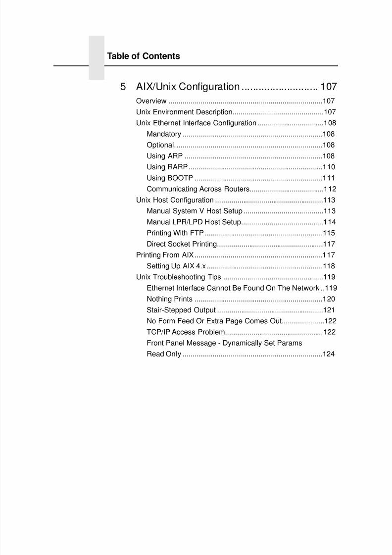
5 AIX/Unix Configuration ........................... 107Overview .............................................................................107
Unix Environment Description.............................................107
Unix Ethernet Interface Configuration .................................108
Mandatory ......................................................................108
Optional..........................................................................108
Using ARP .....................................................................108
Using RARP...................................................................110
Using BOOTP ................................................................111
Communicating Across Routers.....................................112
Unix Host Configuration ......................................................113
Manual System V Host Setup........................................113
Manual LPR/LPD Host Setup.........................................114
Printing With FTP...........................................................115
Direct Socket Printing.....................................................117
Printing From AIX................................................................117
Setting Up AIX 4.x..........................................................118
Unix Troubleshooting Tips ..................................................119
Ethernet Interface Cannot Be Found On The Network ..119Nothing Prints ................................................................120
Stair-Stepped Output .....................................................121
No Form Feed Or Extra Page Comes Out.....................122
TCP/IP Access Problem.................................................122
Front Panel Message - Dynamically Set Params
Read Only ......................................................................124
7/23/2019 54458302 IBM 6400
http://slidepdf.com/reader/full/54458302-ibm-6400 9/349
Table of Contents
6 Novell Configuration............................... 125Overview .............................................................................125
Novell Environment Description ..........................................125
Novell Ethernet Interface Configuration ..............................126
Using HTML Forms ........................................................127
Novell Host Configuration....................................................128
NetWare Version 3.x PSERVER Setup .........................128
NetWare Version 3.x RPRINTER Setup ........................131
NetWare Version 4.x and 5.x PSERVER Setup.............134
NetWare Version 4.x and 5.x RPRINTER Setup ...........137
Novell Troubleshooting Tips................................................139
NetWare 3.x - No PSERVER Connection......................140
NetWare 4.x and 5.x- No PSERVER Connection ..........141
7 Novell Configuration For
10/100Base-T Interfaces........................ 143Overview .............................................................................143
Novell Ethernet Interface Configuration (10/100Base-T) ....144
Preferred File Server (NDS and Bindery Setups) ..........144Setting Password Security
(NDS and Bindery Setups).............................................147
Adjusting Polling Time
(NDS and Bindery Setups).............................................149
Changing The Ethernet Interface Name
(NDS and Bindery Setups).............................................150
Changing The Ethernet Interface Frame Type
(NDS and Bindery Setups).............................................152
Changing The Ethernet Interface Mode(NDS and Bindery Setups).............................................153
Setting The Ethernet Interface NDS Context
(NDS Setups) .................................................................154
Setting The Ethernet Interface Preferred NDS Tree
(NDS Setups) .................................................................155
7/23/2019 54458302 IBM 6400
http://slidepdf.com/reader/full/54458302-ibm-6400 10/349
Table of Contents
Novell Host Configuration (10/100Base-T) .........................156
NDS PSERVER Setup (Netware 4.x/5.x).......................157Bindery PSERVER Setup
(Netware 3.x, Netware 4.x, and Netware 5.x) ................160
Referencing A Bindery Queue In NDS
(Netware 3.x, Netware 4.x, and Netware 5.x) ................160
RPRINTER/NPRINTER Setup
(Netware 3.x, Netware 4.x, and Netware 5.x) ................161
NDPS Configuration (Netware 4.11 and Above)............164
Troubleshooting (10/100Base-T) ........................................167
PSERVER Setup ...........................................................167RPRINTER/NPRINTER Setup.......................................170
Printing Related .............................................................172
8 iSeries Configuration, ASCII Printer ....... 175Overview .............................................................................175
Configuring iSeries For ASCII Using TCP/IP ......................177
Configuring With ADDTCPIFC.......................................177
Configuring A Router Definition With ADDTCPRTE ......179
Configuring A Local Domain And Hostname..................179Configuring A TCP/IP Host Table Entry.........................179
Configuring The iSeries For Printing ...................................180
Setting Up Printing For ASCII Files................................180
Verify Printing On iSeries ....................................................185
iSeries ASCII Troubleshooting ............................................186
TCP/IP Access Problem.................................................187
Web Browser/HTTP Problem.........................................189
7/23/2019 54458302 IBM 6400
http://slidepdf.com/reader/full/54458302-ibm-6400 11/349
Table of Contents
9 iSeries Configuration, IPDS Printer........ 191Configuring On iSeries As An IPDS Printer.........................191
Printing AFP, IPDS, And SCS Files ...............................191
Requirements.................................................................192
Configuration Checklist ..................................................192
Configuring An iSeries TCP/IP Interface With
ADDTCPIFC...................................................................194
Configuring PSF For IPDS On V3R7 Or V4R1 ..............196
Configuring PSF for IPDS On V4R2 And Above............202
Verifying The IPDS Configuration On iSeries......................209
Sharing The iSeries Printer On The Network......................211
Printer Sharing Parameters............................................211
iSeries Troubleshooting.......................................................213
Cannot PING The Printer...............................................213
PSF Terminates When Initialized...................................213
Spooled Print File Remains In PND Status....................214
Spooled Files Disappear Without Printing......................214
Data Is Being Clipped ....................................................214
10 z/OS Configuration for an IPDSPrinter..................................................... 215Overview .............................................................................215
Requirements.................................................................215
Configuration Checklist ..................................................216
Configuring PSF for z/OS to Print IPDS Files .....................217
Configuration Procedure ................................................217
Verifying a TCP/IP-Attached Printer on z/OS.................227
Sharing IBM 6400i Printers on z/OS ...................................228JES Spool Printer Sharing .............................................228
Port Switching Printer Sharing .......................................230
Handling z/OS Connectivity Problems ................................230
Ping is Not Successful ...................................................230
Ping is Successful ..........................................................231
7/23/2019 54458302 IBM 6400
http://slidepdf.com/reader/full/54458302-ibm-6400 12/349
Table of Contents
11 z/OS Configuration, TN3270E................ 233z/OS Configuration For A TN3270E Printer ........................233
Coax Printer Support FMID.................................................233
Program Materials ...............................................................234
VTAM Definitions For SCS and DSE TN3270E.............235
TCPIP Configuration With TN3270E..............................237
Printer Inventory Manager As Defined With TN3270E...238
Configuration Screens.........................................................247
12 iSeries Configuration, TN5250 ............... 251Setting Up TN5250 Print Queues on iSeries.......................251
Setting Up A TN5250 Connection/Device Via A
Telnet Session ....................................................................252
User Supplied Values ....................................................253
Using Telnet Commands for TN5250..................................253
Command List ................................................................253
Getting Started...............................................................254
TN5250 Job Formatting ......................................................255
Font Identifier (FONT) - Help ..............................................25713 SNMP Installation Instructions ............... 259
Configuring for a *LAN 3812 SNMP Device Description.....259
Configuration Instructions ..............................................259
Varying on the Printer ....................................................265
Problem Areas for Consideration...................................265
Additional Information ....................................................266
7/23/2019 54458302 IBM 6400
http://slidepdf.com/reader/full/54458302-ibm-6400 13/349
Table of Contents
14 Monitoring Printers................................. 267Implementing Printer Management .....................................267
Agent/Manager Model....................................................267
MIB.................................................................................268
SNMP.............................................................................270
The Printer Management Utility Software (PMU)...........270
Monitoring Tools..................................................................270
OS/2 TCP/IP ..................................................................270
Monitoring With AIX NetView/6000................................271
Setting The SNMP Community Name............................271
15 IBM Network Printer Manager................ 273Overview .............................................................................273
16 Commands............................................. 275Command Shell Overview...................................................275
npsh Access Methods....................................................275
Main npsh Command Prefixes.......................................275
Getting Command Help..................................................276
Complete Command List .....................................................276
Store Commands ...........................................................277
Set Commands ..............................................................287
List Commands ..............................................................299
Miscellaneous Commands.............................................303
7/23/2019 54458302 IBM 6400
http://slidepdf.com/reader/full/54458302-ibm-6400 14/349
Table of Contents
17 Extra Features ........................................ 307Ethernet Interface Security..................................................307
Users And Passwords....................................................307
Reset The Ethernet Password .......................................309
TCP Access Lists ...........................................................310
Printer Monitoring And Logging...........................................311
Printer And Print Job Monitoring ....................................311
Printer Logging Through Logpaths ................................312
Ethernet Interface Naming Schemes ..................................314
Notices ................................................... 315Energy Star .........................................................................315
Notices ................................................................................316
Trademarks .........................................................................319
Product Recycling and Disposal .........................................320
Communication Statements ................................................321
Glossary ................................................. 327
7/23/2019 54458302 IBM 6400
http://slidepdf.com/reader/full/54458302-ibm-6400 15/349
13
1 Introduction
Overview
This chapter introduces you to the Ethernet Interface architecture
and special features, as well as providing information on installationand configuration tools.
What Is The Ethernet Interface?
The Ethernet Interface allows you to attach printers on a local areanetwork (LAN) rather than attaching them directly to a host system.Following simple configuration steps, these peripherals can besimultaneously shared with users on the network whether you areusing TCP/IP, NetBIOS over TCP/IP, or IPX (Novell ® ).
The Ethernet Interface package contains an Ethernet Interface toattach itself and the printer to the network. The Ethernet Interface issupplied in one of three forms:
an adapter attached to the printer parallel port
• an integrated Ethernet card
• a wireless Ethernet card.
Throughout this manual, features specific to each EthernetInterface type will be indicated by the sideheads ADAPTER,
INTEGRATED, and WIRELESS.
7/23/2019 54458302 IBM 6400
http://slidepdf.com/reader/full/54458302-ibm-6400 16/349
Chapter 1 Overview
14
What Special Features Are Available?
The Ethernet Interface offers an extensive list of features including:
• built-in HTML forms for easy cross-platform configuration
• availability of remote management software
• a detailed and easy-to-use command shell built-in to thefirmware
• multi-level configuration security through passwords,permission levels, and access lists
• WAN-wide communication access• numerous printer logging methods (e.g., automatic email) to
record printer errors and usage
• remote management through HTML forms, Telnet sessions,rsh/rcmd/remsh commands, SNMP, and pre-defined logmethods
• extensive built-in troubleshooting tools
• built-in telnet and ping clients
• configurable memory usage by disabling protocols anddestination services
• multiple destinations/queues for versatile printer manipulationand distinct print setups
• header and trailer strings to instruct printers on font, pitch,printing, etc.
• flexible naming conventions
• automatic network connection and frame type sensing
• simultaneous printing across all I/O ports and all supported
protocols
• multiple network protocol support
7/23/2019 54458302 IBM 6400
http://slidepdf.com/reader/full/54458302-ibm-6400 17/349
What Special Features Are Available?
15
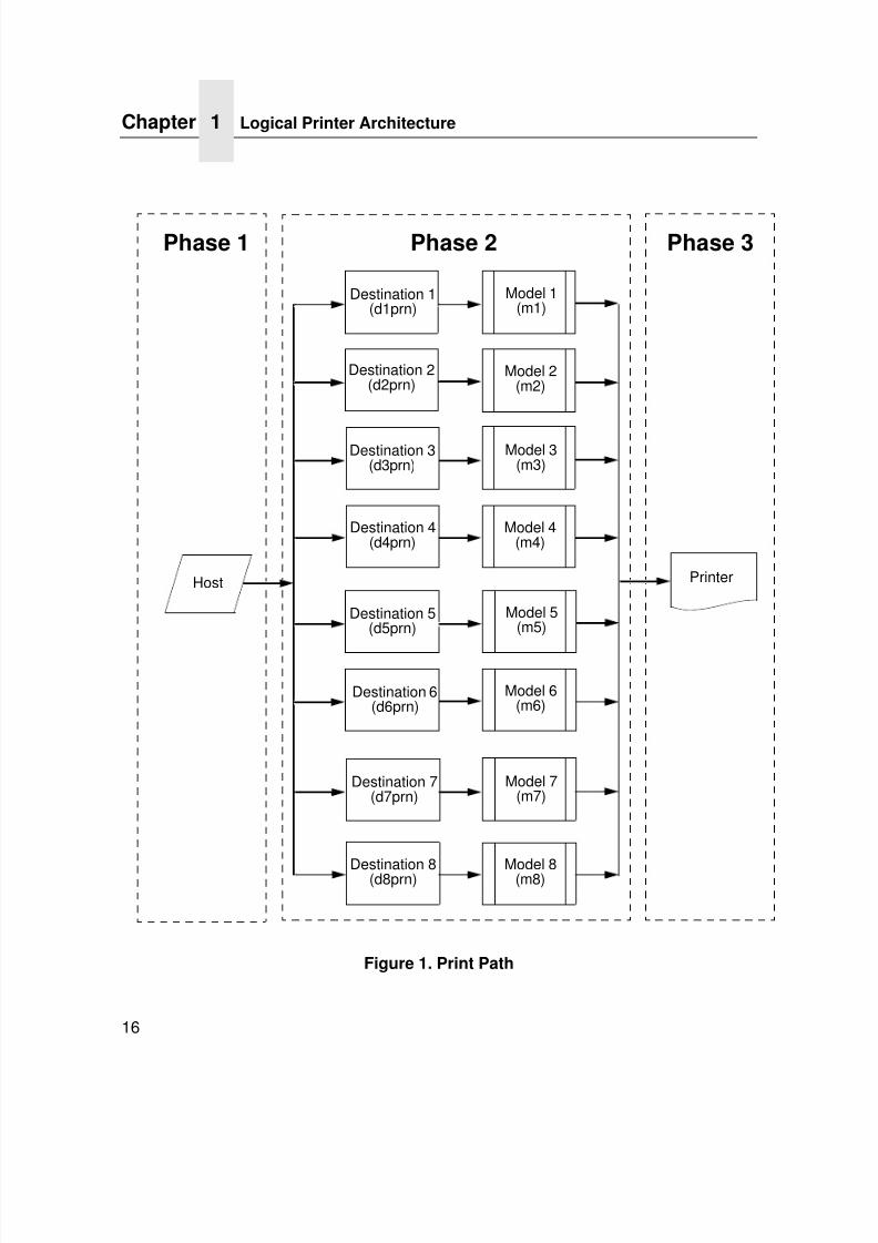
Logical Printer Architecture
The Ethernet Interface implements a logical printer architecturewhich gives the system administrator the possibility to configure theprint server to handle and act upon the print data in several ways.When a print job comes through the print server, there is a certainlogical print path that it follows before it gets to the printer. Eachlogical print path consists of a sequence of logical steps whereextra processing may be performed on the print data before it issent to the printer. This ability to preprocess the print data before itis sent to the printer allows elimination of certain printing problems,
or implementation of printer enhancements that may be difficult andtime consuming to solve or introduce at the system, spool file orqueue level. The preprocess ability is also simplistic to perform atthe print server level.
NOTE: If the printer is configured for IPDS, any reference to“d4prn” should be understood to mean “dipdsprn.” Thisqueue should only be used to print IPDS.
The logical print path for a print job going through the EthernetInterface consists of three different phases:
• Phase 1 - the host sends the job to a destination or queue onthe Ethernet Interface (e.g. d1prn).
• Phase 2 - the print job passes through the associated “model”(e.g. model “m1”) on the Ethernet Interface for any extraprocessing associated with the model.
• Phase 3 - the processed print job is directed to the printer foroutput.
Logical Printer Architecture
7/23/2019 54458302 IBM 6400
http://slidepdf.com/reader/full/54458302-ibm-6400 18/349
Chapter 1 Logical Printer Architecture
16
Figure 1. Print Path
Phase 1 Phase 2 Phase 3
Host
Destination 4(d4prn)
Destination 2(d2prn)
Destination 3(d3prn)
Destination 1(d1prn)
Model 1(m1)
Model 2(m2)
Model 3(m3)
Model 4(m4)
Printer
Destination 8(d8prn)
Destination 6(d6prn)
Destination 7(d7prn)
Destination 5(d5prn)
Model 5(m5)
Model 6(m6)
Model 7(m7)
Model 8(m8)
7/23/2019 54458302 IBM 6400
http://slidepdf.com/reader/full/54458302-ibm-6400 19/349
Destinations/Queues
17
Destinations/Queues
For every I/O port on the Ethernet Interface, there is at least onepre-defined logical print queue or destination to accept print jobsdestined for it. This includes print job that is sent directly to the I/Oport, such as port 9100. These queue or destination names are pre-defined but can be changed by the user.
Models
For every destination or queue, there is a pre-defined model
associated with it. The model defines how the print job will beprocessed as it passes through to the printer. Models are a set ofmini filters that can be used to modify the print data stream. Thefunctions available for each model are as follows:
1. Insert carriage return after line feed
2. Insert a banner page before or after each print job
3. Insert header strings to
• Print in landscape mode
• Print in portrait mode4. Insert trailer strings to
• Reset the printer once the print job completes
• Force the end of the job
• Perform a form feed at the end of the data
7/23/2019 54458302 IBM 6400
http://slidepdf.com/reader/full/54458302-ibm-6400 20/349
Chapter 1 Logical Printer Architecture
18
5. Log one or all of the following information as each print job
passes through the model• Job ID and username
• User ID and three messages per job about the start andfinish
• Checksum value of the data transferred
• Miscellaneous messages from the printer
• Status of the printer based on the port interface signals
6. Load a specific printer configuration before processing a print
job• Specify a printer configuration to be associated with a print
queue.
• When a job is set to that print queue, the associated printerconfiguration will be loaded before the job is processed.
• Feature allows you to define up to eight unique andindependent printer personalities in a single printer.
• Allows you to effectively have eight different printers in one.
7/23/2019 54458302 IBM 6400
http://slidepdf.com/reader/full/54458302-ibm-6400 21/349
10/100Base-T
19
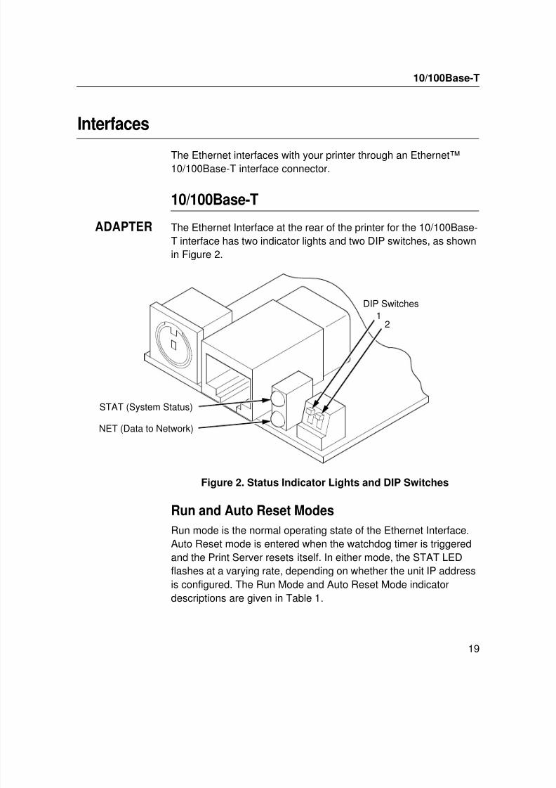
Interfaces
The Ethernet interfaces with your printer through an Ethernet™10/100Base-T interface connector.
10/100Base-T
ADAPTER The Ethernet Interface at the rear of the printer for the 10/100Base-T interface has two indicator lights and two DIP switches, as shownin Figure 2.
Figure 2. Status Indicator Lights and DIP Switches
Run and Auto Reset Modes
Run mode is the normal operating state of the Ethernet Interface.Auto Reset mode is entered when the watchdog timer is triggeredand the Print Server resets itself. In either mode, the STAT LEDflashes at a varying rate, depending on whether the unit IP addressis configured. The Run Mode and Auto Reset Mode indicatordescriptions are given in Table 1.
12
STAT (System Status)
NET (Data to Network)
DIP Switches
7/23/2019 54458302 IBM 6400
http://slidepdf.com/reader/full/54458302-ibm-6400 22/349
Chapter 1 Interfaces
20
Network Indicator
The NET LED displays the status of the network link. When theNET LED is on, link integrity is confirmed. The NET LED flashes offfor 1/3 second when a data packet is being transferred. When theNET LED is off, the network connection has been severed.
Table 1. Run Mode and Auto Reset Mode Indicator Descriptions
STAT Indication Description
OFF flashes on once per second Normal Mode, IP address configured
OFF flashes on two times persecond
IP address not configured
ON flashes off once per second Download (MOS)
ON flashes off twice per second Error
Table 2. NET LED Indicator
NET Indication Description
ON constantly Indicates link integrity
ON flashes off 1/3 second Flashes off 1/3 second each time apacket is transmitted
7/23/2019 54458302 IBM 6400
http://slidepdf.com/reader/full/54458302-ibm-6400 23/349
10/100Base-T
21
Integrated NIC Card LED:
Wireless Network Indicator
WIRELESS The wireless Ethernet Interface has 2 bi-color LEDs which canproduce three colors each: green, red, and yellow (green and redcombined). Table 4 shows the STAT LED states for various sytemconditions:
Table 3. Integrated NIC LED Indicator
NET Indication Description
ON flashes Indicates activity
ON constant Indicates that the link is good at 10 Mbps
ON constant Indicates that the link is good at 100 Mbps
Table 4. Wireless Ethernet Interface STAT LED States
System Condition STAT LED
System is running without an IPaddress.
Green, 2 Hz flash
System is running with an IP address. Green, 1 Hz flash
System error. Red 2Hz flash
System is in upgrade mode with an IPaddress.
Yellow, 1 Hz flash
System is in upgrade mode without anIP address.
Yellow, 2 Hz flash
7/23/2019 54458302 IBM 6400
http://slidepdf.com/reader/full/54458302-ibm-6400 24/349
Chapter 1 Interfaces
22
Table 5 shows the NET LED states for various network conditions
when a WLAN card is inserted into the wireless Ethernet. TheEthernet (wired) interface will not affect the NET LED while aWLAN card is present.
Table 6 shows the NET LED states for various network conditionswhen no WLAN card is found or present.
Table 5. Wireless Ethernet Interface NET LED States
WLAN Network Condition NET LED
Network-link quality is good Green
Network-link quality is fair Yellow
Network-link quality is bad RedNetwork-link not present Off
Network-link present and transmitting Link quality + blink
Table 6. Wireless Ethernet Interface NET LED States(No WLAN)
Wired Ethernet Network Condition(No WLAN)
NET LED
Network-link is present Green
Network-link is not present Off
Network-link present and transmitting Blink
7/23/2019 54458302 IBM 6400
http://slidepdf.com/reader/full/54458302-ibm-6400 25/349
10/100Base-T
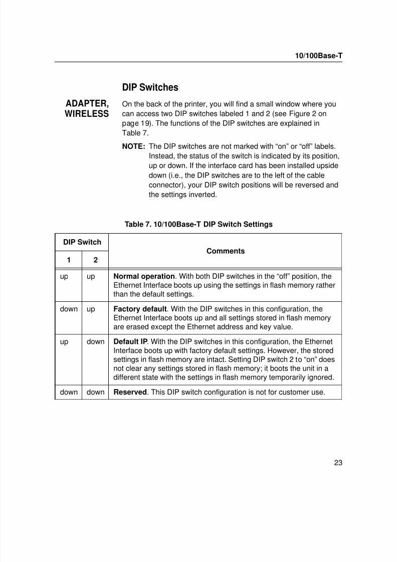
23
DIP Switches
ADAPTER,WIRELESS
On the back of the printer, you will find a small window where youcan access two DIP switches labeled 1 and 2 (see Figure 2 onpage 19). The functions of the DIP switches are explained inTable 7.
NOTE: The DIP switches are not marked with “on” or “off” labels.Instead, the status of the switch is indicated by its position,up or down. If the interface card has been installed upsidedown (i.e., the DIP switches are to the left of the cableconnector), your DIP switch positions will be reversed and
the settings inverted.
Table 7. 10/100Base-T DIP Switch Settings
DIP SwitchComments
1 2
up up Normal operation. With both DIP switches in the “off” position, theEthernet Interface boots up using the settings in flash memory rather
than the default settings.
down up Factory default. With the DIP switches in this configuration, theEthernet Interface boots up and all settings stored in flash memoryare erased except the Ethernet address and key value.
up down Default IP. With the DIP switches in this configuration, the EthernetInterface boots up with factory default settings. However, the storedsettings in flash memory are intact. Setting DIP switch 2 to “on” doesnot clear any settings stored in flash memory; it boots the unit in adifferent state with the settings in flash memory temporarily ignored.
down down Reserved. This DIP switch configuration is not for customer use.
7/23/2019 54458302 IBM 6400
http://slidepdf.com/reader/full/54458302-ibm-6400 26/349
Chapter 1 Interfaces
24
Speed Setting for 10/100Base-T
When the router is set to auto-negotiation enable, the following isthe correct behavior of the Ethernet Interface with each setting:
1. 10mbps Half Duplex
Use parallel detection because the Ethernet Interface is usingforce mode and thus has auto-negotiation disabled.
PORs to Half Duplex. Resets to Half Duplex. Reconnection atswitch maintains Half Duplex.
2. 10mbps Full Duplex
Use parallel detection because the Ethernet Interface is usingforce mode and thus has auto-negotiation disabled.
PORs to Half Duplex. Resets to Half Duplex. Reconnection atswitch maintains Half Duplex.
3. 100mbps Half Duplex
Use parallel detection because the Ethernet Interface is usingforce mode and thus has auto-negotiation disabled.
PORs to Half Duplex. Resets to Half Duplex. Reconnection at
switch results in Half Duplex.4. 100mbps Full Duplex
Use parallel detection because the Ethernet Interface is usingforce mode and thus has auto-negotiation disabled.
PORs to Half Duplex. Resets to Half Duplex. Reconnection atswitch results in Half Duplex.
5. Ethernet in Auto mode in 100mbps FD environment
Use auto negotiation to the highest common local and remote
capability, i.e. 100FD in this case.PORs to 100/FD. Resets to 100/FD. Reconnection at switchremains 100/FD.
7/23/2019 54458302 IBM 6400
http://slidepdf.com/reader/full/54458302-ibm-6400 27/349
Speed Setting for 10/100Base-T
25
6. Ethernet in Auto mode in 10mbps HD environment
(determined using 10hd hub)Use auto-negotiation to the highest common local and remotecapability, i.e. 100FD in this case.
PORs to 10HD. Resets to 10HD. Reconnection at switchmaintains 10HD.
NOTE: With parallel detection, only speed can be determined. Theduplex mode sets to half duplex.
Conventions Used In This ManualAll uppercase print indicates control panel keys.Example: Press the CLEAR key, then press the ONLINE key.
Quotation marks (“ ”) indicate messages on the Liquid CrystalDisplay (LCD).Example: Press the ONLINE key. “OFFLINE” appears on the LCD.
Command syntax and examples are formatted as follows:
• The Courier font in boldface indicates commands that you
type. For example:At the prompt, type:
ping ftp.CompanyWebsite.com
• Regular Courier font indicates references to command syntaxand output. For example:
The ftp.CompanyWebsite.com site is working properly.
• Variable values are shown in italics in command syntax, output,and in text. For example:
ping ipname
The ipname is working properly.
Conventions Used In This Manual

7/23/2019 54458302 IBM 6400
http://slidepdf.com/reader/full/54458302-ibm-6400 28/349
Chapter 1 Notes and Notices
26
Notes and Notices
For your safety and to protect valuable equipment, read and complywith the notes included in this manual. A description follows:
NOTE: A Note gives you helpful information and tips about printeroperation and maintenance.
7/23/2019 54458302 IBM 6400
http://slidepdf.com/reader/full/54458302-ibm-6400 29/349
27
2 Installation And Configuration
InstallationThe Ethernet Interface provides an RJ-45 connector for10/100Base-T (UTP) networks.
Connecting To The Network
To attach the Ethernet Interface to a network, plug the networkcable into the Ethernet Interface connector.
Watch the LEDs in the rear of the printer as they cycle through the
power-on self-test. When the test is complete, the STAT LED willbegin to flash.
7/23/2019 54458302 IBM 6400
http://slidepdf.com/reader/full/54458302-ibm-6400 30/349
Chapter 2 Configuration Tools
28
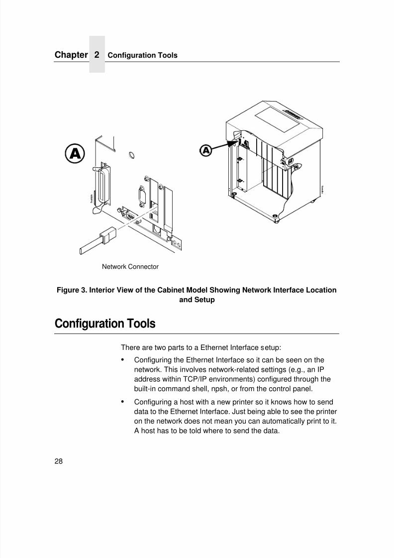
Figure 3. Interior View of the Cabinet Model Showing Network Interface Locationand Setup
Configuration Tools
There are two parts to a Ethernet Interface setup:
• Configuring the Ethernet Interface so it can be seen on thenetwork. This involves network-related settings (e.g., an IPaddress within TCP/IP environments) configured through the
built-in command shell, npsh, or from the control panel.• Configuring a host with a new printer so it knows how to send
data to the Ethernet Interface. Just being able to see the printeron the network does not mean you can automatically print to it.A host has to be told where to send the data.
A A
Network Connector
7/23/2019 54458302 IBM 6400
http://slidepdf.com/reader/full/54458302-ibm-6400 31/349
Configuration Using The Control Panel
29
NOTE: Some network environments do not require any network
settings to be configured on the Ethernet Interface.However, all network setups require configuration on thehost end.
Configuration Using The Control Panel
You can set Ethernet Interface settings from the printer controlpanel.
CAUTION When the printer is first powered on, the message “ETHERNET
ADAPTER IS BEING INITIALIZED” displays on the control
panel. To prevent a loss of Ethernet Interface configuration
information, do not change the Ethernet Interface settings
while this message is displayed. When the initialization is
complete, the message “ETHERNET ADAPTER IS READY”
displays, and you can safely change the Ethernet Interface
settings from the control panel.
1. You can set any of three listed parameters from the printercontrol panel. These parameters are located in the EthernetAddress, Adapter Address, or Wireless Address menu. Arrange
to have an IBM service technician install the Ethernet Interfacecard if it is not already installed; this is not a customerinstallable feature.
2. Power on the printer. The message “ETHERNET ADAPTER ISBEING INITIALIZED” appears when the printer is powered on.Configuration can be done after the “ETHERNET ADAPTER ISREADY” message appears.
3. Disable the Power Saver mode before starting this procedure,see the 6400i Setup Guide for instructions.
7/23/2019 54458302 IBM 6400
http://slidepdf.com/reader/full/54458302-ibm-6400 32/349
Chapter 2 Configuration Tools
30
4. Always print an Ethernet Adapter test page before performing
any updates or network configuration using the following steps:For 6400i printers:
a. Press STOP to take the printer offline. The printer is in theNOT READY state.
b. Press Scroll↑ + Scroll↓ simultaneously to unlock theprinter menu.
c. Press Menu to display OPERATOR MENU.
d. Press Scroll until “Operator Print Test” displays, then press
Enter.e. Press Scroll until the following displays:
“ETHERNET TEST PAGE” for the integrated or wirelessEthernet.
“ADAPTER TEST PAGE” for the Ethernet Adapter.
f. Press Enter.
5. Verify the current Ethernet Interface firmware version number.
NOTE: Firmware exists within the Ethernet Interface and the
printer itself. Each firmware is a separate entity with its ownversion number. Please pay close attention to the type offirmware referenced in the remaining sections of thisdocument.
The Ethernet Interface version should be 1.1.3 or higher for 10/ 100Base-T Ethernet adapters. If the Ethernet Interface versionis current, skip to step 6 below. If the Ethernet Interface versionis not current, you need to update both the Ethernet Interfaceand printer firmware.
If you need to update the printer firmware, you must do so now.
After the update is complete, you must restart this instructionfrom the beginning. To upgrade the printer firmware, contactyour IBM service representative.
7/23/2019 54458302 IBM 6400
http://slidepdf.com/reader/full/54458302-ibm-6400 33/349
Configuration Using The Control Panel
31
CAUTION Turning off the printer before the firmware update is complete
may permanently damage the Ethernet Interface adapter.
Updating the printer firmware takes time. Please be patient
and wait for the “ETHERNET ADAPTER IS READY” message
to display on the LCD. Do not turn off the printer before it has
completed the firmware download procedure. The LCD will
display “ONLINE / ETHERNET ADAPTER IS READY” when the
download is complete. Wait for this message before turning
off the printer.
6. To enter IP Address parameters, do the following:
a. Press STOP to get to the NOT READY state.b. Press Scroll↑ + Scroll↓ to unlock the printer menu.
c. Press Menu to display OPERATOR MENU.
d. Press Scroll until NETWORK SETUP displays, then pressEnter.
e. Press Scroll until ADAPTER ADDRESS or ETHERNETADDRESS displays, then press Enter.
f. Press Scroll until IP ADDRESS displays, then press Enter.
g. Press Enter again, then Scroll to choose an IP addressoctet to change. Press Enter.
h. Press Scroll to choose the desired value for the octet, thenpress Enter. The new value is shown with an asterisk.Press Return.
i. Repeat steps d and e until you have set all IP addressoctets to the desired value.
j. Press Return until ADAPTER ADDRESS or ETHERNETADDRESS is on the first display line.
k. Press Scroll to choose other IP parameters to change,then follow the above steps for each of these.
l. When finished, press Return multiple times until NOTREADY displays.
m. Press Start.

7/23/2019 54458302 IBM 6400
http://slidepdf.com/reader/full/54458302-ibm-6400 34/349
Chapter 2 Configuration Tools
32
n. Wait for “ETHERNET ADAPTER IS READY” to display.
o. Press Scroll↑ + Scroll↓ to lock the printer menu.
7. Put the printer online and wait for the “ETHERNET ADAPTERIS READY” message to display on the front panel. Placing theprinter online starts the Ethernet Interface IP Address andNetmask update process. This process will take severalminutes.
NOTE: If you do not put the printer online, the setting you justentered will not take effect. Do not turn the printer off untilyou see the “ETHERNET ADAPTER IS READY” message.
If you turn the printer off before the new values are writtento memory in the Ethernet Interface adapter, you will needto repower the printer and repeat steps 6 and 7 aboveimmediately.
8. Once the “ETHERNET ADAPTER IS READY” messagedisplays, you may enter the Gateway Address by repeatingfront panel steps 6 and 7 above. This will ensure the correctNetmask becomes associated with the Gateway value youenter. From the front panel navigate to the Gateway Addressand enter the appropriate value. You must press ENTER afterinputting each segment of the Gateway Address.
9. Put the printer online and wait for the “ETHERNET ADAPTERIS READY” message to display on the front panel.
10. Enable the Power Saver mode if desired.
7/23/2019 54458302 IBM 6400
http://slidepdf.com/reader/full/54458302-ibm-6400 35/349
Wireless Ethernet Interface Configuration Using The Control Panel
33
Wireless Ethernet Interface Configuration Using
The Control Panel
WIRELESS NOTE: The Access Point must be configured according to themanufacturer's installation guide.
To configure Wireless Ethernet Interface, configure the ethernetand wireless IP addresses so they can be seen on the network.This includes several network-related settings (e.g., an IP addresswithin TCP/IP environments) configured through the built-incommand shell, npsh, or from the control panel.
IP Address Configuration
You can set the wireless Ethernet Interface IP settings from theprinter control panel.
CAUTION When the printer is first powered on, the message
“ETHERNET ADAPTER IS BEING INITIALIZED” displays on the
control panel. To prevent a loss of Ethernet Interface
configuration information, do not change the Ethernet
Interface settings while this message displays. When the
initialization is complete, “ETHERNET ADAPTER IS READY”
displays, and you can safely change the Ethernet Interface
settings from the control panel.
You need to set both the ethernet and wireless network IPaddresses according to the TCP/IP environment that the printer isconnected to. There are four parameters accessed from the printercontrol panel that are IP address related. These parameters arelocated in the "ETHERNET ADDRESS" menu and the "WIRELESSADDRESS" menu:
• IP Address
This is the host for IP addresses that have four segments. They aredisplayed as SEG1, SEG2, SEG3, and SEG4 which can be set toany value in the range of 0 to 255.
7/23/2019 54458302 IBM 6400
http://slidepdf.com/reader/full/54458302-ibm-6400 36/349
Chapter 2 Configuration Tools
34
• Subnet Mask
This is the subnet mask for the host IP that has four segments.They are displayed as SEG1, SEG2, SEG3, and SEG4 which canbe set to any value in the range of of 0 to 255.
• Gateway Address
This is the gateway IP addresses that have four segments. Theyare displayed as SEG1, SEG2, SEG3, and SEG4 which can be setto any value in the range of 0 to 255.
• DHCP
The DHCP can be configured to Enable or Disable.
Wireless Parameter Configuration
Certain "WIRELESS PARAMETERS" must be configured to matchthe Access Point settings:
NOTE: The "ETHERNET PARAMETERS" are configured thesame way as the 10/100 Ethernet external EthernetInterface. Please refer to the PrintNet menu.
• OPERATION MODE
This is the operation mode of the wireless network. The optionsinclude “Infrastructure” or “Ad Hoc” mode. This must match theAccess Point's configuration.
• SSID NAME
This is the Service Set Identifier which must be identical to theAccess Point's SSID name. The SSID name can be configured to amaximum of 32 alphanumeric characters. The SSID name andalphanumeric characters are divided into three parts in the controlpanel menu as "SSID Name (01-15)", "SSID Name (16-30)" and
"SSID Name (31-32)".
7/23/2019 54458302 IBM 6400
http://slidepdf.com/reader/full/54458302-ibm-6400 37/349
Wireless Ethernet Interface Configuration Using The Control Panel
35
• MINIMUM TRANSFER RATE
Allows you to set the minimum speed at which the Wireless Optionwill accept a connection (in million bits per second).
This is the wireless transfer rate, and can be set to either “enable”or “disable.” It is set to “enable” when the operation mode is"Infrastructure" so that the Ethernet Interface can automaticallydetect the optimal transfer rate. If the operation mode is "Ad Hoc"and the transfer rate is known, the user can enable or disable thecorresponding transfer rate in the menus "Xfer Rate 1Mb", "XferRate 2Mb", "Xfer Rate 5.5Mb" or "Xfer Rate 11Mb".
• CHANNELThis is the frequency used for wireless communication. The2.4GHz band spectrum is divided into different channels (1-15). It isset to "Default" so that the Ethernet Interface can detect the correctchannel to communicate with the Access Point in infrastructuremode. If the operation mode is "Ad Hoc" and the channel is known,the user can set the corresponding channel in this menu.
• ANTENNA DIVERSITY
This is used to select the antenna for communication. It is
recommended to set to "Diverse" for the Ethernet Interface todetect for optimal communication. It can also be set to "Primary" or"Auxiliary".
• PREAMBLE
This is the preamble used in the wireless packets. It isrecommended to set to "Default" so that the Ethernet Interface candetect the correct preamble. The preamble is approximately 8 bytesof the packet header generated by the AP is and attached to thepacket prior to transmission. The preamble length is transmissiondata rate dependent. The "short" preamble is 50% shorter than the"long" preamble. It must match the Access Point's preambleconfiguration.
7/23/2019 54458302 IBM 6400
http://slidepdf.com/reader/full/54458302-ibm-6400 38/349
Chapter 2 Configuration Tools
36
• POWER MANAGEMENT
This option allows you to set power-save mode and sleep time. Avalue specifying the sleep time in milliseconds will be provided. Ifset to zero, power-save mode will be disabled.
• INTERNATIONAL MODE
When enabled, the Wireless option adapts to internationalfrequency requirements in Europe.
• SIGNAL STRENGTH
This menu displays the strength of the wireless signal.
NOTE: This is a display value only and cannot be changed.• DEFAULT WEP KEY
The default key must match the Access Point's configuration. If theAccess Point is configured to use "Open System", the default keyshould be set to 0. If the Access Point is configured to use 40-bit or128-bit WEP encryption key, the encryption key must be set to thesame setting as the Access Point's setting. See the followingsection on how to set up the encryption key. In addition, there arefour keys (1-4) that an Access Point can use. If the Access Point is
set to use key 1, the default key must be set to 1 to correspond tothe Access Point's setting.
Encryption Key Configuration
As mentioned above, there are four encryption keys that can beconfigured through the control panel. For each encryption key x(where x can be 1 to 4), the following control menu can be used toconfigure the key:
• KEY FORMAT
This is the format of the key. It can be set to either ASCII orHexadecimal.
• KEY WIDTH
This is the number of bits used for encryption. This can be set toeither 40 Bits or 128 Bits and must match the Access Point'sconfiguration.
7/23/2019 54458302 IBM 6400
http://slidepdf.com/reader/full/54458302-ibm-6400 39/349
Wireless Ethernet Interface Configuration Using The Control Panel
37
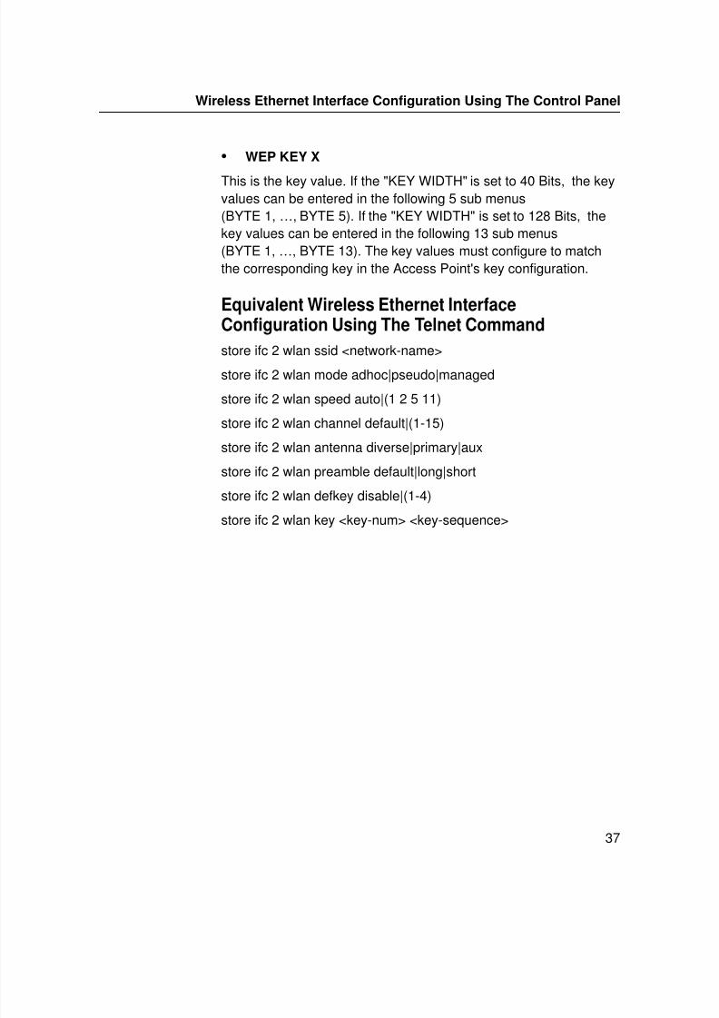
• WEP KEY X
This is the key value. If the "KEY WIDTH" is set to 40 Bits, the keyvalues can be entered in the following 5 sub menus(BYTE 1, …, BYTE 5). If the "KEY WIDTH" is set to 128 Bits, thekey values can be entered in the following 13 sub menus(BYTE 1, …, BYTE 13). The key values must configure to matchthe corresponding key in the Access Point's key configuration.
Equivalent Wireless Ethernet InterfaceConfiguration Using The Telnet Command
store ifc 2 wlan ssid <network-name>store ifc 2 wlan mode adhoc|pseudo|managed
store ifc 2 wlan speed auto|(1 2 5 11)
store ifc 2 wlan channel default|(1-15)
store ifc 2 wlan antenna diverse|primary|aux
store ifc 2 wlan preamble default|long|short
store ifc 2 wlan defkey disable|(1-4)
store ifc 2 wlan key <key-num> <key-sequence>
7/23/2019 54458302 IBM 6400
http://slidepdf.com/reader/full/54458302-ibm-6400 40/349
Chapter 2 Configuration Tools
38
Ethernet Interface Verification
Before performing the verification, you must connect the EthernetInterface card to the network.
1. Print an Ethernet test page (following the steps on page -29) toverify the settings you made.
2. Verify the Netmask is correct in two locations on the Ethernettest page:
• NETWORK INTERFACES
• TCP/IP ROUTING TABLE
The Netmask must be the same in both locations. For example,if the Netmask is listed as 255.255.255.0 in NETWORKINTERFACES and is listed as 255.255.255.255 in the TCP/IPROUTING TABLE, they do not match and you must correct itfor the Gateway. Also, if a Gateway Address was entered,verify that “xxx.xxx.xxx.xxx is alive” is printed under the DefaultGateway Ping Test, where xxx.xxx.xxx.xxx is the GatewayAddress. If a Gateway Address was not entered, the DefaultGateway Ping test is not required and will not display on the
page.If the Netmask does not match, complete the following steps:
a. Place the printer offline.
b. Using the front panel, modify the Gateway value to 0.0.0.0.(non-configured).
c. Place the printer online and wait for the “ETHERNETADAPTER IS READY” message to display.
d. Place the printer offline and enter the Gateway Addressyou desire.
e. Place the printer online and wait for the “ETHERNETADAPTER IS READY” message. This saves the newGateway Address.
Your Ethernet Interface is now configured and connected to yournetwork.
7/23/2019 54458302 IBM 6400
http://slidepdf.com/reader/full/54458302-ibm-6400 41/349
HTML Forms
39
HTML Forms
The Ethernet Interface settings can be configured over TCP/IPthrough a standard Web browser. The Ethernet Interface Webpages provide a handy way to access some of the commands builtinto the print server.
NOTE: If a router is used, make sure a Gateway value isconfigured.
To access the Ethernet Interface home page:
1. Make sure the print server has an IP address and Subnet Mask
so it is recognizable on your TCP/IP network.2. Make sure your network station can successfully ping the
Ethernet Interface over the network.
3. Direct your Web browser to the URL:http://IPaddress
(e.g., http://192.75.11.9)where IPaddress is the IP address of your Ethernet Interface.
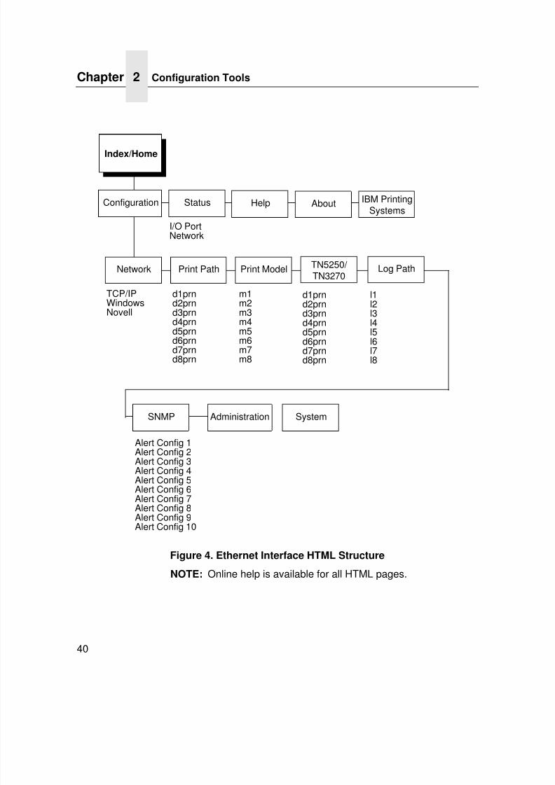
The Ethernet Interface HTML structure is divided into severalmenus as shown in Figure 4.
7/23/2019 54458302 IBM 6400
http://slidepdf.com/reader/full/54458302-ibm-6400 42/349
Chapter 2 Configuration Tools
40
Figure 4. Ethernet Interface HTML Structure
NOTE: Online help is available for all HTML pages.
Index/Home
Configuration
I/O PortNetwork
TCP/IPWindowsNovell
d1prnd2prnd3prnd4prnd5prnd6prnd7prnd8prn
m1m2m3m4m5m6m7m8
Alert Config 1Alert Config 2Alert Config 3Alert Config 4Alert Config 5Alert Config 6Alert Config 7Alert Config 8Alert Config 9Alert Config 10
Status Help About
AdministrationSNMP
Print ModelPrint PathNetwork
TN5250/
TN3270
d1prnd2prnd3prnd4prnd5prnd6prnd7prnd8prn
System
IBM PrintingSystems
Log Path
l1l2l3l4l5l6l7l8
7/23/2019 54458302 IBM 6400
http://slidepdf.com/reader/full/54458302-ibm-6400 43/349
HTML Forms
41
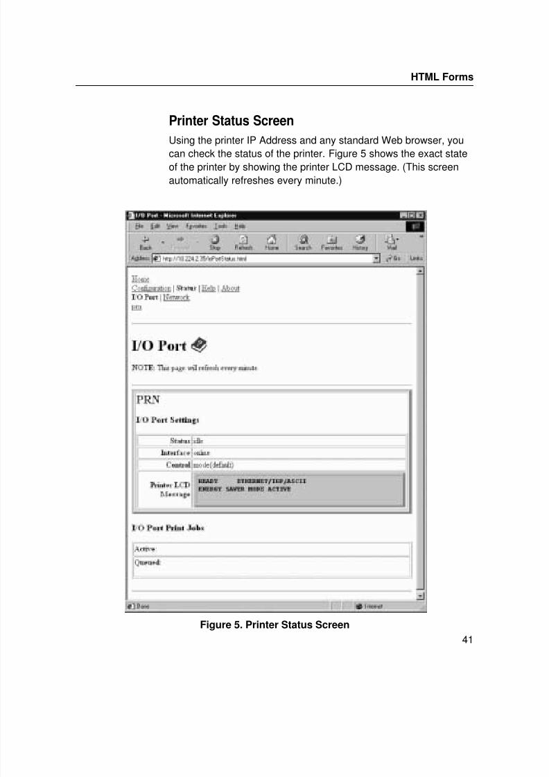
Printer Status Screen
Using the printer IP Address and any standard Web browser, youcan check the status of the printer. Figure 5 shows the exact stateof the printer by showing the printer LCD message. (This screenautomatically refreshes every minute.)
Figure 5. Printer Status Screen
7/23/2019 54458302 IBM 6400
http://slidepdf.com/reader/full/54458302-ibm-6400 44/349
Chapter 2 Configuration Tools
42
Configuration Alternatives
Besides the HTML forms and software provided, the EthernetInterface internal command shell, npsh, can also be reached usingTelnet and Remote Shell.
Telnet
A TCP/IP command that helps configure Ethernet Interface settingsremotely. A TCP/IP host starts a Telnet session with the printserver and logs into the device command shell to alter and viewsettings.
Example:
telnet 192.75.11.9
Remote Shell
A TCP/IP command that helps configure print server settingsremotely. A TCP/IP host uses this command to remotely execute asingle command on the Ethernet Interface.
Example:
rsh spike list prnThis command remotely executes the npsh command list prn on the Ethernet Interface named spike.
7/23/2019 54458302 IBM 6400
http://slidepdf.com/reader/full/54458302-ibm-6400 45/349
43
3 Embedded Ethernet Interface Web Page
OverviewThe Ethernet Interface comes with an extremely powerful printermanagement tool that allows you to monitor, configure, andmanage both the printer and its print job. The Ethernet Interfacecomes with an embedded web server that allows SystemAdministrators and users access to its printer managementcapabilities from a standard web browser.
The Ethernet Interface printer’s IP address is used as a URL,similar to the URL of an Internet web page. When a web browser is
activated and the printer’s IP address is entered, the printer’sembedded web server will display its home page, with links to theprinter’s status and configuration settings.
All of the Ethernet Interface’s configuration settings are protectedby a password so unauthorized users cannot make changes. Whenyou try to open any of the Ethernet Interface’s configuration pages,you are asked for your user name and password. At the prompt,you need to enter root (unless you have another user configuredwith root privileges) followed by the associated password. If there isno password, just press ENTER . For more information on setting
passwords, refer to “Ethernet Interface Security” on page 307.
7/23/2019 54458302 IBM 6400
http://slidepdf.com/reader/full/54458302-ibm-6400 46/349
Chapter 3 Configuration
44
After you configure the Ethernet Interface settings, and click the
SUBMIT button on the related form, re-power the Ethernet Interfaceshould to ensure the latest settings are in use. To reset theEthernet Interface, go to the System form under the ConfigurationMenu and click the REBOOT button.
The embedded Ethernet Interface Web server gives you the abilityto configure the network adapter, monitor printer status, and tomanage print jobs. The Ethernet Interface Web page structure isdivided into several menus, as shown in Figure 4.
ConfigurationThe Configuration menu items allow you to configure the settingsfor the following items:
• Network - this menu item allows you to change the networksetting for each protocol: TCP/IP, NetBIOS over TCP/IP, andNetware.
• Print Path - this menu item allows you to change the name ofthe destination queues, and define how the print job will bepreprocessed before printing. It allows you to select whatinformation to log, and to specify the SMTP server’s IPaddress.
• Print Model - this menu item displays model settings one at atime.
• Log Path - this menu item displays log path settings one at atime.
• TN5250/3270 - this menu item allows you to configure theTN5250/3270 settings.
7/23/2019 54458302 IBM 6400
http://slidepdf.com/reader/full/54458302-ibm-6400 47/349
45
• SNMP - this menu item allows you to configure the SNMP trap
manager settings. It also allows you to define the printer eventtypes to monitor, and the e-mail address that should receivealert notifications.
• Administration - this menu item allows you to define or changethe printer name, location, description, etc. It also allows you tochange the root and guest user passwords.
• System - this menu item allows you to reboot the EthernetInterface, or restore its settings to the factory default.
Configuration
7/23/2019 54458302 IBM 6400
http://slidepdf.com/reader/full/54458302-ibm-6400 48/349
Chapter 3 Network Configuration
46
Network Configuration
The network configuration allows you to specify the setting for eachnetwork protocol. Beside each protocol name is a checkbox whichallows you to enable or disable each protocol depending on yournetwork printing needs.
NOTE: TCP/IP is the only supported protocol which is alwaysenabled.
TCP/IP Network
Figure 6. TCP/IP Network Configuration
Interface
The two edit fields contain the Ethernet Interface's IP address and
subnet mask. The check boxes enable the RARP, BOOTP, andDHCP protocols, which are alternate methods of assigning IPaddresses. On most networks, you want to enter a permanent IPaddress and subnet mask and disable RARP, BOOTP, and DHCP.However, if your network requires one of these, you should clearthe IP address (and possibly the subnet mask) fields and ensurethat the appropriate check box is selected.
7/23/2019 54458302 IBM 6400
http://slidepdf.com/reader/full/54458302-ibm-6400 49/349
Windows Network (NetBIOS TCP/IP)
47
Routing
The routing table tells the Ethernet Interface which router orgateway to use to access other subnets or hosts. In mostsituations, you can simply add your router's IP address as thedefault router. All packets destined for other subnets will beforwarded to the default router for delivery to the destination host. Ifyou have more complex routing requirements, add static routingentries for specific hosts or networks in the remaining Routing rows.Packets with IP addresses that match a given Destination andMask (from the first two fields in a Routing row) will be routed to therouter/gateway named in the third field. Packets which do not
match any of the listed Destinations and Masks will be routed to thedefault router if one is set.
Windows Network (NetBIOS TCP/IP)
TCP/IP is used for Windows (i.e. Windows NT, Windows 95, andWindows for Workgroups) printing unless another protocol like IPXis available. Therefore, mandatory TCP/IP settings (i.e. IP addressand subnet mask) are necessary on the Ethernet Interface. Go to“TCP/IP Network” on this form to fill in these settings if you haven't
done so already.
Figure 7. Windows Network (NetBIOS TCP/IP) Configuration
Workgroup Name
This name specifies which Windows workgroup the EthernetInterface will reside in.
7/23/2019 54458302 IBM 6400
http://slidepdf.com/reader/full/54458302-ibm-6400 50/349
Chapter 3 Network Configuration
48
Novell Network
ADAPTER,WIRELESS
Novell configuration is supported only on the Ethernet Adapter andWireless Ethernet.
Figure 8. Novell Network Configuration
FrameType
This option determines which framing scheme will be used inprocessing Novell signals. The different types of Ethernet packetformats include:
• Auto Sensing (the default)
• Ethernet II
• Ethernet 802.3
• Ethernet 802.2
• 802.2 Snap
7/23/2019 54458302 IBM 6400
http://slidepdf.com/reader/full/54458302-ibm-6400 51/349
Novell Network
49
Service Type
Allows you to change the Nest Server. The options are:
• Bindery
• NDS
• Auto
File Server
Define a Novell file server for the Ethernet Interface to service aseither a PSERVER or an RPRINTER.
NDS
NDS (Novell Directory Services) is a distributed database ofnetwork information. An NDS contains information that definesevery object on the network. For more information please see yourNovell administrator.
Pserver
Define a password for the Ethernet Interface to use when logging in
to the file server as a PSERVER. This is an optional file serversecurity feature.
Rprinter
Define an RPRINTER setup so the Ethernet Interface knows toservice a PSERVER.NLM on a Novell file server. Define thePSERVER.NLM name, the number of the printer serviced by theEthernet Interface within this PSERVER.NLM, and the destinationon the Ethernet Interface you want the print jobs to pass through.
7/23/2019 54458302 IBM 6400
http://slidepdf.com/reader/full/54458302-ibm-6400 52/349
Chapter 3 Print Path Configuration
50
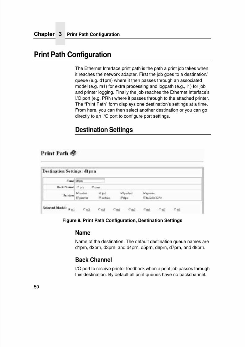
Print Path Configuration
The Ethernet Interface print path is the path a print job takes whenit reaches the network adapter. First the job goes to a destination/ queue (e.g. d1prn) where it then passes through an associatedmodel (e.g. m1) for extra processing and logpath (e.g., l1) for joband printer logging. Finally the job reaches the Ethernet Interface'sI/O port (e.g. PRN) where it passes through to the attached printer.The “Print Path” form displays one destination's settings at a time.From here, you can then select another destination or you can godirectly to an I/O port to configure port settings.
Destination Settings
Figure 9. Print Path Configuration, Destination Settings
Name
Name of the destination. The default destination queue names ared1prn, d2prn, d3prn, and d4prn, d5prn, d6prn, d7prn, and d8prn.
Back Channel
I/O port to receive printer feedback when a print job passes throughthis destination. By default all print queues have no backchannel.
7/23/2019 54458302 IBM 6400
http://slidepdf.com/reader/full/54458302-ibm-6400 53/349
Destination Settings
51
Services
Define what type(s) of print services the destination will support. Bydefault all services are enabled.
Selected Model
Defines the model configuration that is to be associated with thecurrent destination. The default model names are m1, m2, m3, m4,m5, m6, m7, and m8.
Parameters
socket Printing to a TCP port number (e.g. 4000) on theEthernet Interface
lpd Remote printing using the Line Printer Daemon
lpsched System V printing using the “lp” command
ADAPTER,WIRELESS
rprinter Novell's remote printer setup
ADAPTER,WIRELESS
pserver Novell's PSERVER setup
netbios Printing from Windows stations relying onNetBIOS over TCP/IP
ftpd Printing using the File Transfer Protocol (FTP)tn5250/3270 Printing using tn5250/3270 configuration
7/23/2019 54458302 IBM 6400
http://slidepdf.com/reader/full/54458302-ibm-6400 54/349
Chapter 3 Print Path Configuration
52
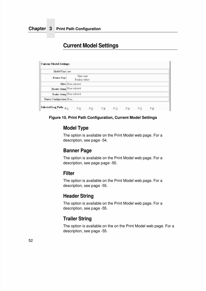
Current Model Settings
Figure 10. Print Path Configuration, Current Model Settings
Model Type
The option is available on the Print Model web page. For adescription, see page -54.
Banner PageThe option is available on the Print Model web page. For adescription, see page page -55.
Filter
The option is available on the Print Model web page. For adescription, see page -55.
Header String
The option is available on the Print Model web page. For adescription, see page -55.
Trailer String
The option is available on the on the Print Model web page. For adescription, see page -55.
7/23/2019 54458302 IBM 6400
http://slidepdf.com/reader/full/54458302-ibm-6400 55/349
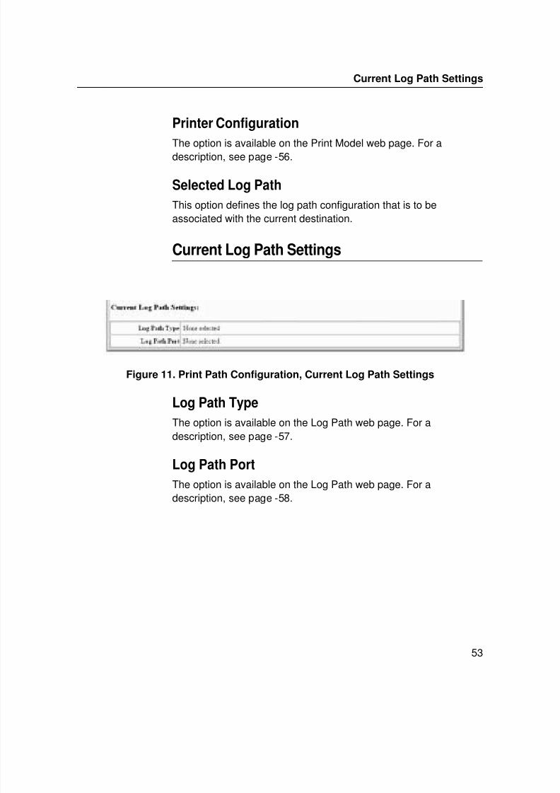
Current Log Path Settings
53
Printer Configuration
The option is available on the Print Model web page. For adescription, see page -56.
Selected Log Path
This option defines the log path configuration that is to beassociated with the current destination.
Current Log Path Settings
Figure 11. Print Path Configuration, Current Log Path Settings
Log Path Type
The option is available on the Log Path web page. For adescription, see page -57.
Log Path Port
The option is available on the Log Path web page. For adescription, see page -58.
7/23/2019 54458302 IBM 6400
http://slidepdf.com/reader/full/54458302-ibm-6400 56/349
Chapter 3 Print Model Configuration
54
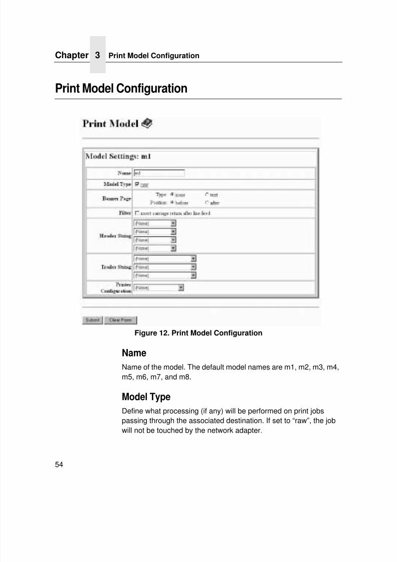
Print Model Configuration
Figure 12. Print Model Configuration
Name
Name of the model. The default model names are m1, m2, m3, m4,m5, m6, m7, and m8.
Model Type
Define what processing (if any) will be performed on print jobspassing through the associated destination. If set to “raw”, the jobwill not be touched by the network adapter.
7/23/2019 54458302 IBM 6400
http://slidepdf.com/reader/full/54458302-ibm-6400 57/349
Current Log Path Settings
55
Banner Page
Tell the Ethernet Interface to produce a banner page with each print job. The type of banner page data can be text. You can also specifywhether the banner page should come at the front or the end of aprint job.
Filter
Specify whether the Ethernet Interface is to add carriage returns toprint jobs passing through that contain solitary linefeeds. This iscommon with Unix text jobs resulting in stair-stepped output.
Header String
Define an escape sequence to be sent to the printer before eachprint job. For example, you may want to send a sequence to printthe job in landscape mode or to a certain tray on the printer. Youcan specify up to four separate sequences per header string. TheEthernet Interface will execute them in order from top to bottom. Ifspecifying fewer than four sequences, be sure to start at the topleaving undefined fields at the bottom.
The most common sequences are listed on the form:
• Print landscape - tells the printer to print in landscape mode.
• Print portrait - tells the printer to print in portrait mode.
Trailer String
Define an escape sequence to be sent to the printer after each print job. For example, you may want to send a sequence to add aformfeed so you don't have to manually press the formfeed buttonon the printer. You may also want to tell the printer to reset itself in
case you have set a header string which tells the printer to dosomething special with the job. You can specify up to threeseparate sequences per trailer string. The Ethernet Interfaceexecutes them in order from top to bottom. If specifying fewer thanfour sequences, be sure to start at the top leaving undefined fieldsat the bottom.
Print Model Configuration
7/23/2019 54458302 IBM 6400
http://slidepdf.com/reader/full/54458302-ibm-6400 58/349
Chapter 3 Print Model Configuration
56
The most common sequences are listed on the form:
• PCL Reset - tells the printer to reset itself once the datacompletes
• End of Transmission (EOT) - tells the printer to force the end ofthe job
• Formfeed - tells the printer to do a formfeed at the end of thedata.
Printer Configuration
Specify a printer configuration number to be loaded beforeprocessing the print job. This ability to associate a printerconfigurations to a logical printer model allows you to define up toeight unique and independent printer personalities in a singleprinter. Using this feature, you effectively have four differentprinters in one.
To associate a printer configuration to the currently selecteddestination queue, just select the desired printer configurationnumber from the drop down list. Once a printer configuration havebeen associated with a destination queue, any print job sent to that
destination queue name will cause the printer to load theassociated printer configuration before processing the print job.
7/23/2019 54458302 IBM 6400
http://slidepdf.com/reader/full/54458302-ibm-6400 59/349
Current Log Path Settings
57
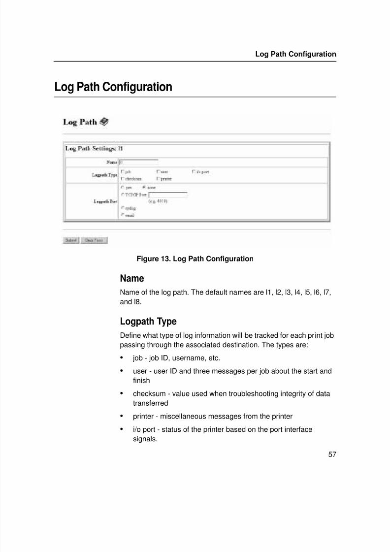
Log Path Configuration
Figure 13. Log Path Configuration
Name
Name of the log path. The default names are l1, l2, l3, l4, l5, l6, l7,and l8.
Logpath Type
Define what type of log information will be tracked for each print jobpassing through the associated destination. The types are:
• job - job ID, username, etc.
• user - user ID and three messages per job about the start andfinish
• checksum - value used when troubleshooting integrity of datatransferred
• printer - miscellaneous messages from the printer
• i/o port - status of the printer based on the port interfacesignals.
Log Path Configuration
7/23/2019 54458302 IBM 6400
http://slidepdf.com/reader/full/54458302-ibm-6400 60/349
Chapter 3 Log Path Configuration
58
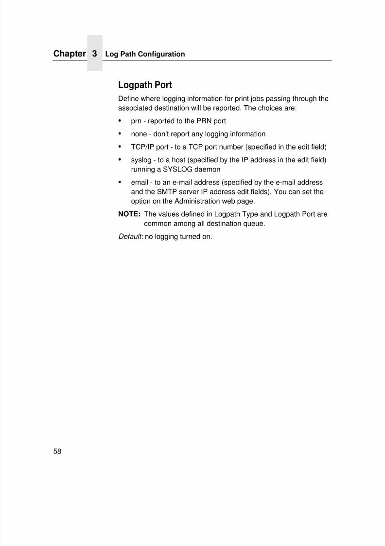
Logpath Port
Define where logging information for print jobs passing through theassociated destination will be reported. The choices are:
• prn - reported to the PRN port
• none - don't report any logging information
• TCP/IP port - to a TCP port number (specified in the edit field)
• syslog - to a host (specified by the IP address in the edit field)running a SYSLOG daemon
• email - to an e-mail address (specified by the e-mail address
and the SMTP server IP address edit fields). You can set theoption on the Administration web page.
NOTE: The values defined in Logpath Type and Logpath Port arecommon among all destination queue.
Default: no logging turned on.
7/23/2019 54458302 IBM 6400
http://slidepdf.com/reader/full/54458302-ibm-6400 61/349
Current Log Path Settings
59
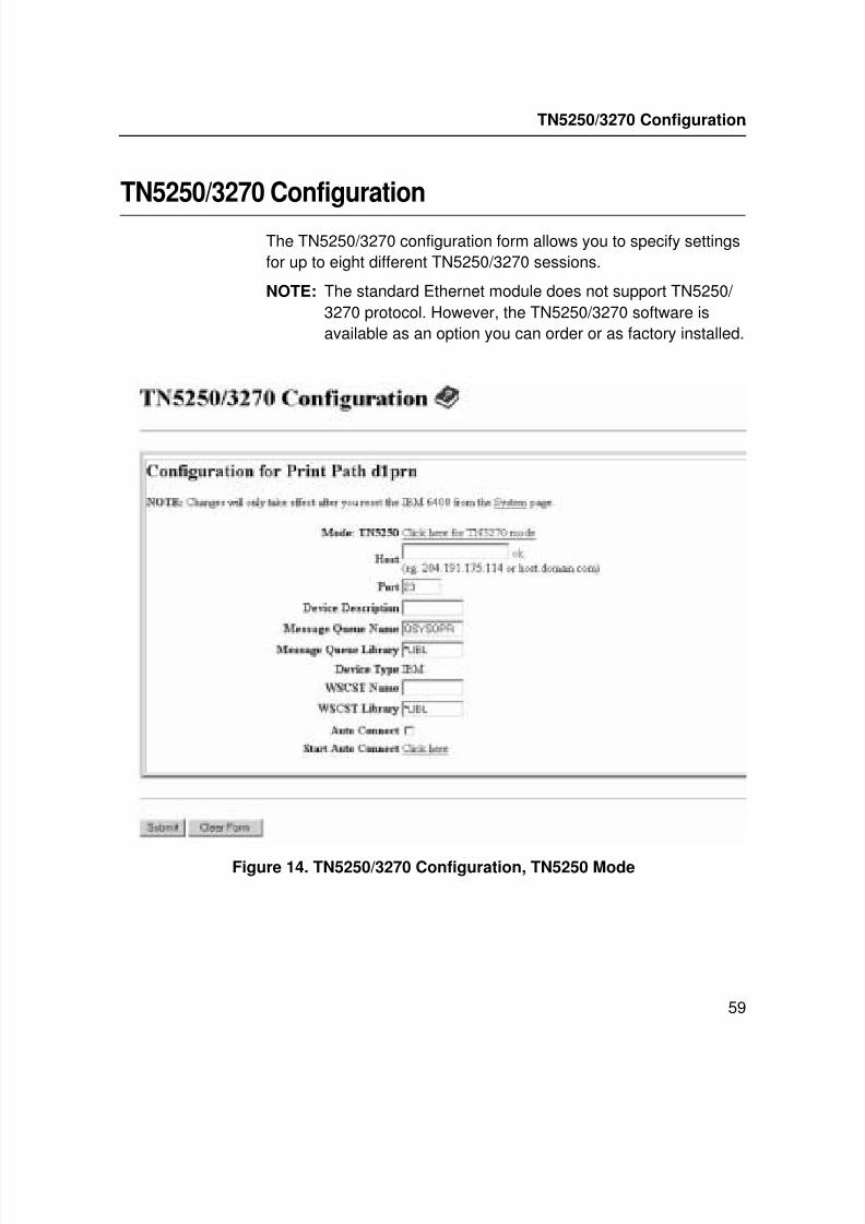
TN5250/3270 Configuration
The TN5250/3270 configuration form allows you to specify settingsfor up to eight different TN5250/3270 sessions.
NOTE: The standard Ethernet module does not support TN5250/ 3270 protocol. However, the TN5250/3270 software isavailable as an option you can order or as factory installed.
Figure 14. TN5250/3270 Configuration, TN5250 Mode
TN5250/3270 Configuration
7/23/2019 54458302 IBM 6400
http://slidepdf.com/reader/full/54458302-ibm-6400 62/349
Chapter 3 TN5250/3270 Configuration
60
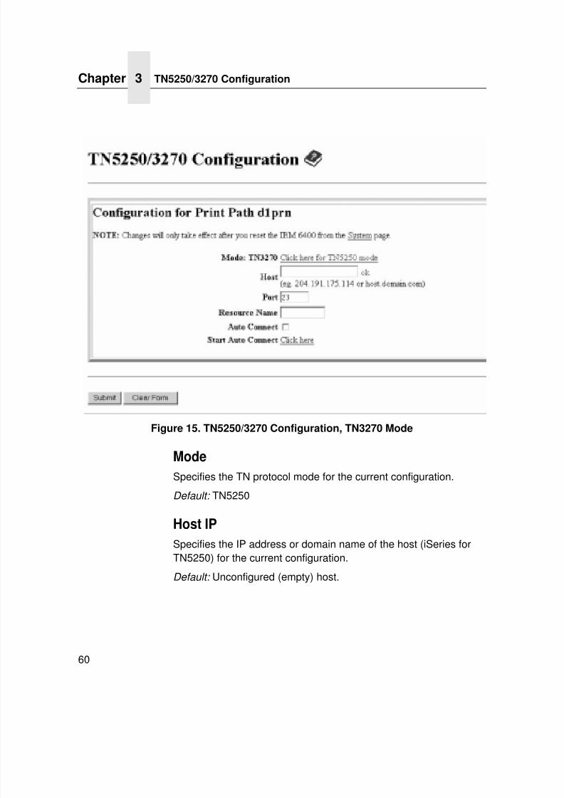
Figure 15. TN5250/3270 Configuration, TN3270 Mode
Mode
Specifies the TN protocol mode for the current configuration.
Default: TN5250
Host IP
Specifies the IP address or domain name of the host (iSeries for
TN5250) for the current configuration.Default: Unconfigured (empty) host.
7/23/2019 54458302 IBM 6400
http://slidepdf.com/reader/full/54458302-ibm-6400 63/349
Current Log Path Settings
61
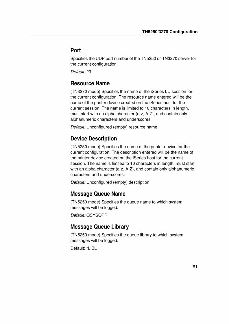
Port
Specifies the UDP port number of the TN5250 or TN3270 server forthe current configuration.
Default: 23
Resource Name
(TN3270 mode) Specifies the name of the iSeries LU session forthe current configuration. The resource name entered will be thename of the printer device created on the iSeries host for thecurrent session. The name is limited to 10 characters in length,
must start with an alpha character (a-z, A-Z), and contain onlyalphanumeric characters and underscores.
Default: Unconfigured (empty) resource name
Device Description
(TN5250 mode) Specifies the name of the printer device for thecurrent configuration. The description entered will be the name ofthe printer device created on the iSeries host for the currentsession. The name is limited to 10 characters in length, must start
with an alpha character (a-z, A-Z), and contain only alphanumericcharacters and underscores.
Default: Unconfigured (empty) description
Message Queue Name
(TN5250 mode) Specifies the queue name to which systemmessages will be logged.
Default: QSYSOPR
Message Queue Library(TN5250 mode) Specifies the queue library to which systemmessages will be logged.
Default: *LIBL
TN5250/3270 Configuration
7/23/2019 54458302 IBM 6400
http://slidepdf.com/reader/full/54458302-ibm-6400 64/349
Chapter 3 TN5250/3270 Configuration
62
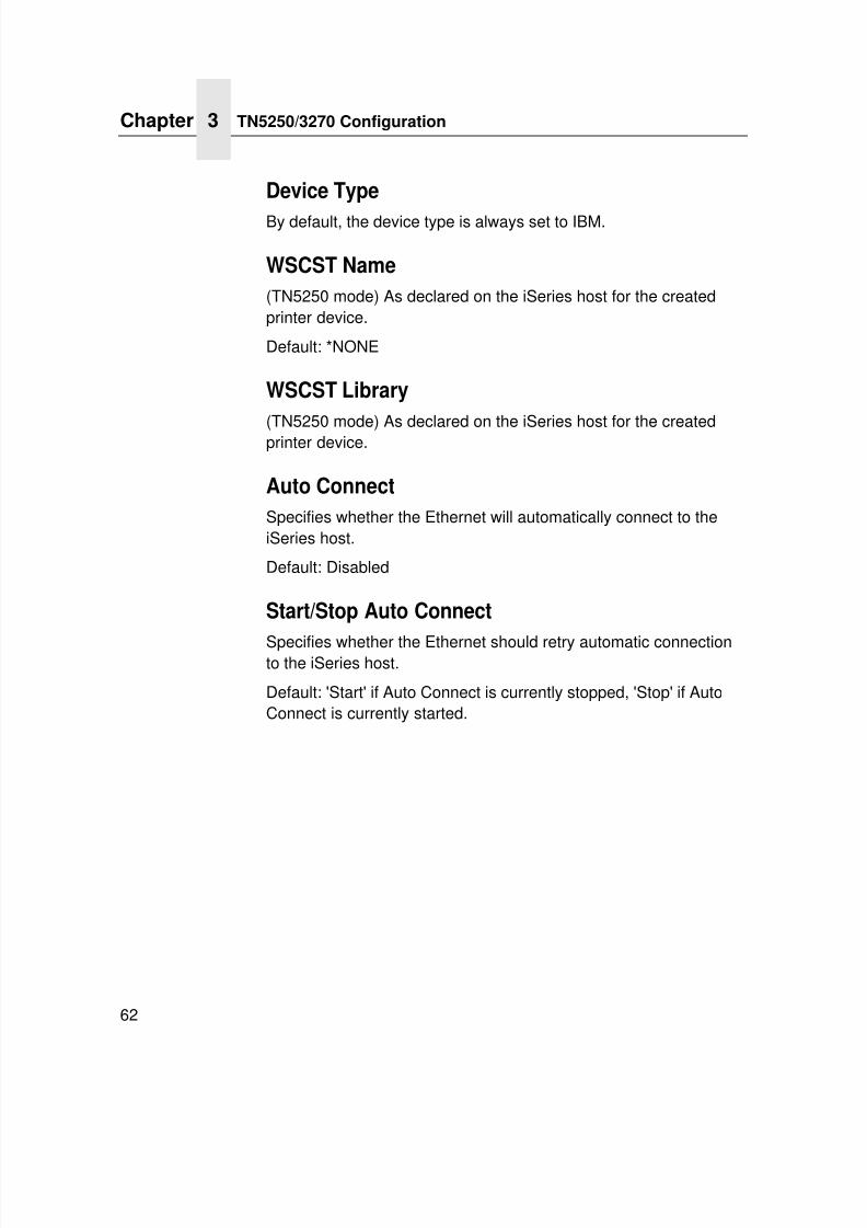
Device Type
By default, the device type is always set to IBM.
WSCST Name
(TN5250 mode) As declared on the iSeries host for the createdprinter device.
Default: *NONE
WSCST Library
(TN5250 mode) As declared on the iSeries host for the createdprinter device.
Auto Connect
Specifies whether the Ethernet will automatically connect to theiSeries host.
Default: Disabled
Start/Stop Auto Connect
Specifies whether the Ethernet should retry automatic connectionto the iSeries host.
Default: 'Start' if Auto Connect is currently stopped, 'Stop' if AutoConnect is currently started.
7/23/2019 54458302 IBM 6400
http://slidepdf.com/reader/full/54458302-ibm-6400 65/349
Current Log Path Settings
63
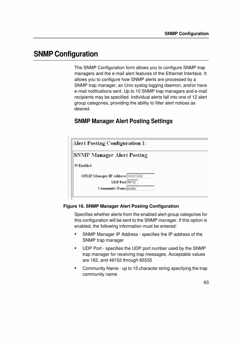
SNMP Configuration
The SNMP Configuration form allows you to configure SNMP trapmanagers and the e-mail alert features of the Ethernet Interface. Itallows you to configure how SNMP alerts are processed by aSNMP trap manager, an Unix syslog logging daemon, and/or havee-mail notifications sent. Up to 10 SNMP trap managers and e-mailrecipients may be specified. Individual alerts fall into one of 12 alertgroup categories, providing the ability to filter alert notices asdesired.
SNMP Manager Alert Posting Settings
Figure 16. SNMP Manager Alert Posting Configuration
Specifies whether alerts from the enabled alert group categories forthis configuration will be sent to the SNMP manager. If this option isenabled, the following information must be entered:
• SNMP Manager IP Address - specifies the IP address of the
SNMP trap manager
• UDP Port - specifies the UDP port number used by the SNMPtrap manager for receiving trap messages. Acceptable valuesare 162, and 49152 through 65535
• Community Name - up to 15 character string specifying the trapcommunity name.
SNMP Configuration
7/23/2019 54458302 IBM 6400
http://slidepdf.com/reader/full/54458302-ibm-6400 66/349
Chapter 3 SNMP Configuration
64
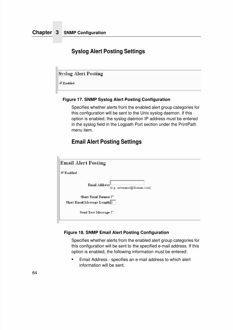
Syslog Alert Posting Settings
Figure 17. SNMP Syslog Alert Posting Configuration
Specifies whether alerts from the enabled alert group categories for
this configuration will be sent to the Unix syslog daemon. If thisoption is enabled, the syslog daemon IP address must be enteredin the syslog field in the Logpath Port section under the PrintPathmenu item.
Email Alert Posting Settings
Figure 18. SNMP Email Alert Posting Configuration
Specifies whether alerts from the enabled alert group categories forthis configuration will be sent to the specified e-mail address. If thisoption is enabled, the following information must be entered:
• Email Address - specifies an e-mail address to which alertinformation will be sent.
7/23/2019 54458302 IBM 6400
http://slidepdf.com/reader/full/54458302-ibm-6400 67/349
Current Log Path Settings
65
• Short E-mail Format - specifies whether a short (15-80
character) alert e-mail message should be sent.If enabled, the message will contain the alert description, theseverity level, and device name (unless the length of themessage exceeds the Short E-mail Message Length, in whichcase the message will be truncated.
If disabled, the message will contain additional informationincluding the device name and location, alert description, alertgroup, and alert severity level, and printer status.
Default: Disabled
• Short E-mail Message Length - specifies the maximum size ofthe short e-mail message. Acceptable values are 15 to 80characters.
Default: 80 characters
• Send Test Message - provides a way to test the validity of thee-mail address/SMTP server address. If checked, a testmessage will be sent to the specified e-mail address when thesubmit button is pressed.
Default: All alert groups are disabled by default.
If the alert message is to be sent to a cellular phone or pager, theShort Email Format option should be enabled. Once this option isenabled, you may specify the maximum e-mail message length(15-80 characters). When enabled, the message will contain thealert description, the severity level, and device name (unless thelength of the message exceeds the Short Email Message Length, inwhich case the message will be truncated).
If the Short Email format is disabled, the message will containadditional information including the device name and location, alert
description, alert group, alert severity level, and printer status.To test the validity of the e-mail address and the SMTP serveraddress, enable the Send Test Message option. If the Send TestMessage box is checked, a test message will be sent to thespecified email address when the submit button is pressed.
SNMP Configuration
7/23/2019 54458302 IBM 6400
http://slidepdf.com/reader/full/54458302-ibm-6400 68/349
Chapter 3 SNMP Configuration
66
Alert Groups
Figure 19. SNMP Alert Groups Configuration
Specifies which alert groups are enabled for reporting for thisconfiguration. When an alert occurs that is contained in one of theenabled alert groups, it will be posted to the specified SNMPmanager, Unix syslog daemon, and/or e-mail address. Thefollowing table describes which printer events belongs to whichAlert Group.
Table 8. Alert Groups and Printer Events
Alert Group Printer Events
Offline Printer is OfflineHold Print Time Out
Warning COMM CheckInvalid AddressCU Time OutCU Not EnabledFile System Full
File ExistHex Dump ModeHalf Speed ModePrinter WarmPrint Head Warm2B-Toner Density Too High2C-Toner Density Too Low
7/23/2019 54458302 IBM 6400
http://slidepdf.com/reader/full/54458302-ibm-6400 69/349
Current Log Path Settings
67
Media Input Load PaperPaper Out Time OutFanfold Paper EmptyNo Fanfold Paper63-CutSheet Feeder FailCutsheet Pick MissNo Paper TrayPaper Jam at Entrance
Cutsheet Cover OpenCutsheet Paper EmptyTray Mismatch
Media Output Stacker FullStacker Jam Time OutStacker Full Time OutStacker Fault Time OutStacker JamStacker FaultStack Over FlowStack Under Flow
Stacker FailStacker Interlock FailStacker Not Ready
Table 8. Alert Groups and Printer Events
Alert Group Printer Events
SNMP Configuration
7/23/2019 54458302 IBM 6400
http://slidepdf.com/reader/full/54458302-ibm-6400 70/349
Chapter 3 SNMP Configuration
68
Media Path Clear Paper JamPaper Jam Time OutPaper Jam FuserPaper Jam ExitCutsheet Path OpenPaper Jam at DrumPaper Jam at FuserPaper Jam at Exit
Tractor MTR FWD Speed ErrorTracker MTR BKWD Speed ErrorPaper Jam at EntranceCutsheet Motor FailCutsheet Feeder FailClear Jam at Fuser InputClear Jam at Fuser ExitClear Jam Near TOF Lever
Marker Ribbon Stall Time OutRibbon Ink OutRibbon Stall
Ribbon DriveShuttle Over SpeedRibbon FaultRibbon DetectedPrint Head UpRibbon BrokenRibbon Load BadRibbon Take-up Full2A-Toner EmptyAdd TonerInstall Toner Cup
Cutter Cutter FaultCutter Fail
Bar Code Barcode Fail SpecificationBarcode Quiet Zone Too SmallBarcode Improper Data Format
Table 8. Alert Groups and Printer Events
Alert Group Printer Events
7/23/2019 54458302 IBM 6400
http://slidepdf.com/reader/full/54458302-ibm-6400 71/349
Current Log Path Settings
69
NOTE: Not all of the alerts are available on all of the printers. Thealerts available for monitoring will depend on the printertype and the options installed on the printer.
Scanner Unscannable Check MediaPoor Scanning Check Head and HeatPoor Scanning Inspect HeadPoor Scanning Check MediaContrast Too Low Check Media
Intervention These are error messages that needsome kind of user intervention to solvethem.
Consumable Ribbon LowToner Low
Label Label PresentGap Not Detected
Table 8. Alert Groups and Printer Events
Alert Group Printer Events
SNMP Configuration
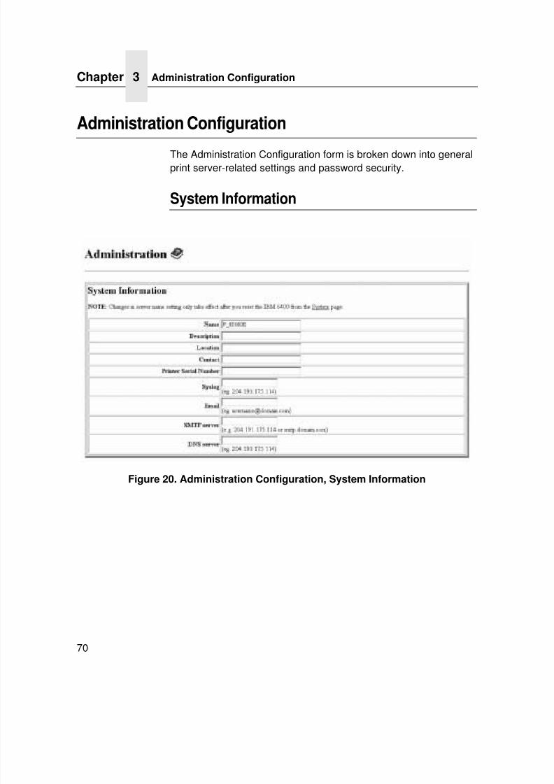
7/23/2019 54458302 IBM 6400
http://slidepdf.com/reader/full/54458302-ibm-6400 72/349
Chapter 3 Administration Configuration
70
Administration Configuration
The Administration Configuration form is broken down into generalprint server-related settings and password security.
System Information
Figure 20. Administration Configuration, System Information
7/23/2019 54458302 IBM 6400
http://slidepdf.com/reader/full/54458302-ibm-6400 73/349
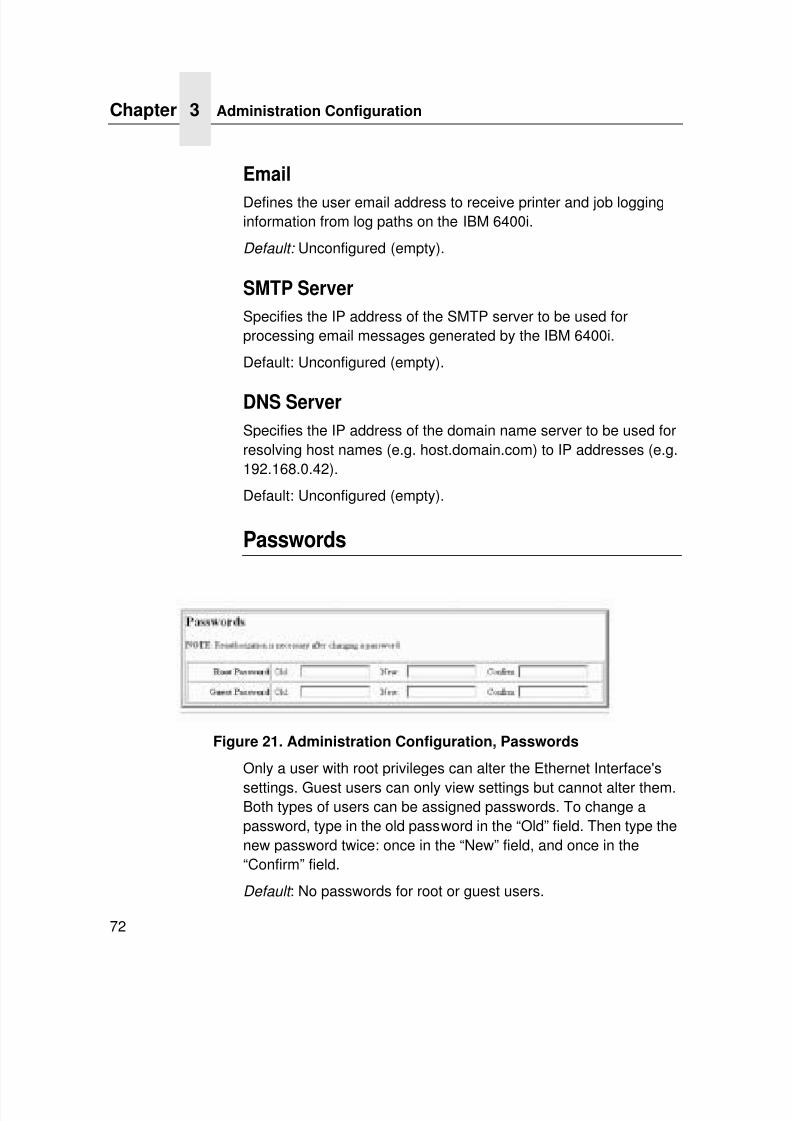
7/23/2019 54458302 IBM 6400
http://slidepdf.com/reader/full/54458302-ibm-6400 74/349
Chapter 3 Administration Configuration
72
Defines the user email address to receive printer and job logginginformation from log paths on the IBM 6400i.
Default: Unconfigured (empty).
SMTP Server
Specifies the IP address of the SMTP server to be used forprocessing email messages generated by the IBM 6400i.
Default: Unconfigured (empty).
DNS Server
Specifies the IP address of the domain name server to be used forresolving host names (e.g. host.domain.com) to IP addresses (e.g.192.168.0.42).
Default: Unconfigured (empty).
Passwords
Figure 21. Administration Configuration, Passwords
Only a user with root privileges can alter the Ethernet Interface's
settings. Guest users can only view settings but cannot alter them.Both types of users can be assigned passwords. To change apassword, type in the old password in the “Old” field. Then type thenew password twice: once in the “New” field, and once in the“Confirm” field.
Default : No passwords for root or guest users.
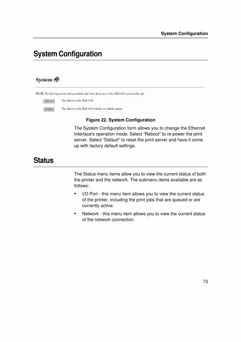
7/23/2019 54458302 IBM 6400
http://slidepdf.com/reader/full/54458302-ibm-6400 75/349
Passwords
73
System Configuration
Figure 22. System Configuration
The System Configuration form allows you to change the EthernetInterface's operation mode. Select “Reboot” to re-power the printserver. Select “Default” to reset the print server and have it comeup with factory default settings.
Status
The Status menu items allow you to view the current status of both
the printer and the network. The submenu items available are asfollows:
• I/O Port - this menu item allows you to view the current statusof the printer, including the print jobs that are queued or arecurrently active.
• Network - this menu item allows you to view the current statusof the network connection.
System Configuration
7/23/2019 54458302 IBM 6400
http://slidepdf.com/reader/full/54458302-ibm-6400 76/349
Chapter 3 IBM Printing Systems
74
Status - I/O Port
The I/O Port Status form allows you to remotely see what ishappening on the Ethernet Interface I/O port. The port's status anda list of active and queued jobs will be displayed. You can cancel a
job (as long as you have permission to) by clicking on the Cancelicon beside the desired job. If you see “waiting” in the “Status” line,this indicates the network adapter is either waiting for data from thehost or for feedback from the printer. If you see “blocked” in thisline, this indicates the printer is not allowing the Ethernet Interfaceto send anymore data. The printer could be busy processing data it
has already received or it could be in an error state.The printer status display is automatically refreshed every minute.
NOTE: You cannot cancel a print job with an IPDS Emulation. Donot click the Cancel icon.
Status - Network
This form allows you to view the current status of the network. Thestatistical data provided is broken down by network protocol. You
can use this form to troubleshoot network-related problems.
IBM Printing Systems
The IBM Printing Systems web site which contains productinformation, technical support, and more.
7/23/2019 54458302 IBM 6400
http://slidepdf.com/reader/full/54458302-ibm-6400 77/349
75
4 WindowsConfiguration
OverviewThis chapter details a complete Windows configuration setupincluding:
• Identifying the Ethernet Interface on the network using TCP/IPas the underlying protocol
• Configuring the Ethernet Interface with its mandatory TCP/IPsettings(IP address and subnet mask)
• Configuring a new printer on the Windows station
Windows Environment Description
The Ethernet Interface supports network printing under Windowsenvironments by using TCP/IP. In a Windows NT ® setup, pureTCP/IP is used as the network protocol whereas with Windows 95/ 98® or Windows Millennium® , NetBIOS is used over TCP/IP.
The ideal configuration is a network printer defined on the NT/2000
server to be shared by Windows 95/98/Millennium clients.However, any Windows station can also go directly to the EthernetInterface.
7/23/2019 54458302 IBM 6400
http://slidepdf.com/reader/full/54458302-ibm-6400 78/349
Chapter 4 Windows Ethernet Interface Configuration
76
Windows Ethernet Interface Configuration
The IP address and subnet mask are mandatory TCP/IP settingsand are needed before the print server can be detected on thenetwork. There are also additional optional settings. This sectionoffers alternative methods for configuring your Ethernet Interface ina Windows environment and describes some of the more commonoptional settings available.
Mandatory
Since TCP/IP is used for Windows printing, the Ethernet Interfacemust be configured with a minimum of an IP address and subnetmask before it can be seen on the network.
Optional
Additional settings, like routing entries, can be configured. Thisallows communication across subnets when no other router exists.
You can configure the Ethernet Interface from the printer control
panel, Web browser, host commands, or other IBM utility software.To configure these options, see “Configuration Tools” on page 28.
Configuration Using ARP
To configure the Ethernet Interface with its IP settings using amanual arp command:
1. Log on to a Windows station with TCP/IP loaded and locatedon the same subnet as the Ethernet Interface.
2. Find the Ethernet address for the Ethernet Interface on theconfiguration printout. It must be entered as part of thisprocedure.
7/23/2019 54458302 IBM 6400
http://slidepdf.com/reader/full/54458302-ibm-6400 79/349
Configuration Using ARP
77
3. Use the arp command to add an entry into the Windows
station ARP table for the Ethernet Interface. This is the mostcommon syntax for this command:
Syntax:
arp -s ipaddress ethernetaddress
Example for Microsoft ® TCP stacks:
arp -s 192.75.11.9 00-80-72-07-00-60
This example specifies a Ethernet Interface using IP address192.75.11.9 and Ethernet address 00-80-72-07-00-60.
4. Check if the ARP entry was accepted.
arp -a
You should see an entry in the listed ARP table with the IPaddress and Ethernet address specified in Step 3.
5. Ping this IP address to see if the Ethernet Interface can beseen on your network.
At this point, you should be able to communicate with theEthernet Interface from your local Windows station. This meansthe print server knows about an IP address and subnet maskand has these settings in its current memory. However, if the
Ethernet Interface is power cycled, these settings willdisappear unless you store them into flash memory. To do this:
a. Load a Web browser on your Windows station and direct itto the URL:http://EthernetInterfaceIPaddress/
networkConf.html
(e.g., http://192.75.11.9/networkConf.html).
NOTE:If prompted for a “User ID” and password first, typeroot for the ID and press ENTER at the password
prompt (since there is no password by default).b. At the “Network Configuration” HTML form that displays,
click in the field below the “IP Address” heading and type inthe IP address for the Ethernet Interface.
7/23/2019 54458302 IBM 6400
http://slidepdf.com/reader/full/54458302-ibm-6400 80/349
Chapter 4 Windows Ethernet Interface Configuration
78
c. Under the “Subnet Mask” heading, enter the Ethernet
Interface subnet mask.NOTE:If you would like to communicate with the Ethernet
Interface from across routers, you will need to fill in anentry within the “Routing” section. Please see“Communicating Across Routers” on page 78 for moredetails.
6. Click on the SUBMIT button when done and physically repowerthe printer to make the new settings take effect.
Communicating Across RoutersSince Windows environments rely on TCP/IP to communicate withthe Ethernet Interface, crossing routers becomes an issue.
After you have followed one of the Ethernet Interface configurationmethods mentioned, most likely you will only be able tocommunicate with the print server from the same subnet. Thismeans any hosts across a router will not be able to see yourEthernet Interface. In order for hosts across a router to see yourEthernet Interface, store a default
router/gateway within the print server so that any packets destinedfor another subnet get forwarded to this router automatically. Therouter (or series of routers) can then take over, ensuring thepackets get to their final destination on another subnet on yournetwork.
To configure a default router/gateway within the Ethernet Interface:
1. Load a Web browser on your Windows station and direct it tothe URL:http://EthernetInterfaceIPaddress/
networkConf.html
(e.g., http://192.75.11.9/networkConf.html).
NOTE: If prompted for a “User ID” and password first, type in root for the ID and press ENTER at the password prompt (sincethere is no password by default).
7/23/2019 54458302 IBM 6400
http://slidepdf.com/reader/full/54458302-ibm-6400 81/349
Changing Workgroup Names
79
2. At the “Network Configuration” HTML form that displays, click in
the first field below the “Gateway” heading and type in the IPaddress of the default router/gateway for the Ethernet Interfacesubnet.
3. Click on the SUBMIT button when done and physically repowerthe print server to make the new settings take effect.
Changing Workgroup Names
Windows environments define groups of related computers as“workgroups.” By default, “WORKGROUP” is the name that is
assigned to the Ethernet Interface workgroup. However, you maywant to change this to suit your network better. To do this:
1. Load a Web browser on your Windows station and direct it tothe URL:http://EthernetInterfaceIPaddress/
networkConf.html
(e.g., http://192.75.11.9/networkConf.html).
NOTE: If prompted for a “User ID” and password first, type in root for the ID and press ENTER at the password prompt (since
there is no password by default).2. At the “Network Configuration” HTML form that displays,
search for the “Windows (NetBIOS TCP/IP)” section andhighlight the “Workgroup Name” field.
3. Type in the new workgroup name for the Ethernet Interface.
4. Click on the SUBMIT button when done and physically repowerthe print server to make the new settings take effect.
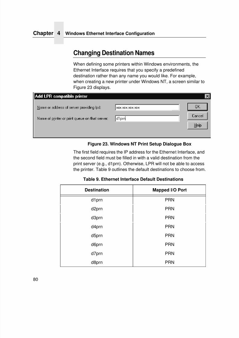
7/23/2019 54458302 IBM 6400
http://slidepdf.com/reader/full/54458302-ibm-6400 82/349
Chapter 4 Windows Ethernet Interface Configuration
80
Changing Destination Names
When defining some printers within Windows environments, theEthernet Interface requires that you specify a predefineddestination rather than any name you would like. For example,when creating a new printer under Windows NT, a screen similar toFigure 23 displays.
Figure 23. Windows NT Print Setup Dialogue Box
The first field requires the IP address for the Ethernet Interface, andthe second field must be filled in with a valid destination from theprint server (e.g., d1prn). Otherwise, LPR will not be able to accessthe printer. Table 9 outlines the default destinations to choose from.
Table 9. Ethernet Interface Default Destinations
Destination Mapped I/O Port
d1prn PRN
d2prn PRN
d3prn PRN
d4prn PRN
d5prn PRNd6prn PRN
d7prn PRN
d8prn PRN
7/23/2019 54458302 IBM 6400
http://slidepdf.com/reader/full/54458302-ibm-6400 83/349
Changing Destination Names
81
This name can be changed to something more meaningful using
the built-in HTML forms. To do this:1. Load a Web browser on your Windows station and direct it to
the URL:http://EthernetInterfaceIPaddress/
networkConf.html
(e.g., http://192.75.11.9/networkConf.html).
NOTE: If prompted for a “User ID” and password first, type in root for the ID and press ENTER at the password prompt (sincethere is no password by default).
2. At the “Print Path Configuration” HTML form that displays,select a destination link from the top of the page to bring up theappropriate destination form. By default, you should see a linenear the top of the form showing the destinations listed inTable 9.
3. Once the desired destination HTML form displays, highlight the“Name” field and type in the new name for this destination.
4. Click on the SUBMIT button when done and physically repowerthe print server to make the new setting take effect.
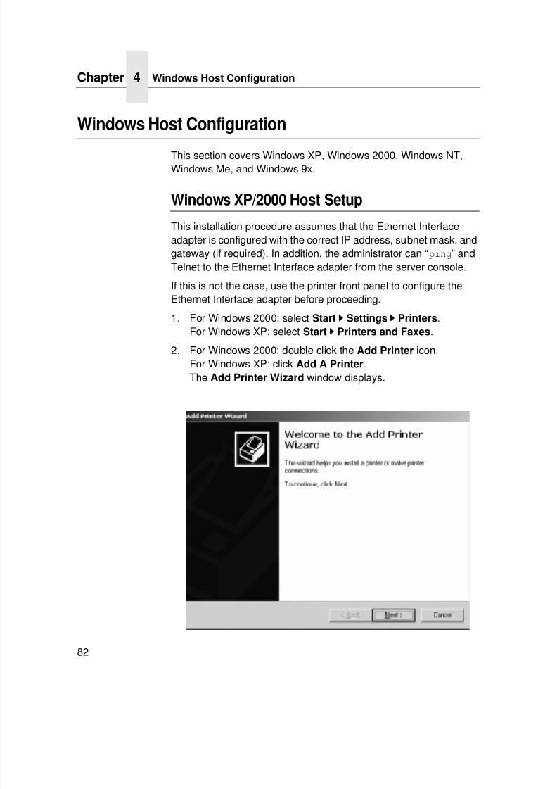
7/23/2019 54458302 IBM 6400
http://slidepdf.com/reader/full/54458302-ibm-6400 84/349
Chapter 4 Windows Host Configuration
82
Windows Host Configuration
This section covers Windows XP, Windows 2000, Windows NT,Windows Me, and Windows 9x.
Windows XP/2000 Host Setup
This installation procedure assumes that the Ethernet Interfaceadapter is configured with the correct IP address, subnet mask, andgateway (if required). In addition, the administrator can “ping” andTelnet to the Ethernet Interface adapter from the server console.
If this is not the case, use the printer front panel to configure theEthernet Interface adapter before proceeding.
1. For Windows 2000: select Start Settings Printers.For Windows XP: select Start
Printers and Faxes.
2. For Windows 2000: double click the Add Printer icon.For Windows XP: click Add A Printer.The Add Printer Wizard window displays.
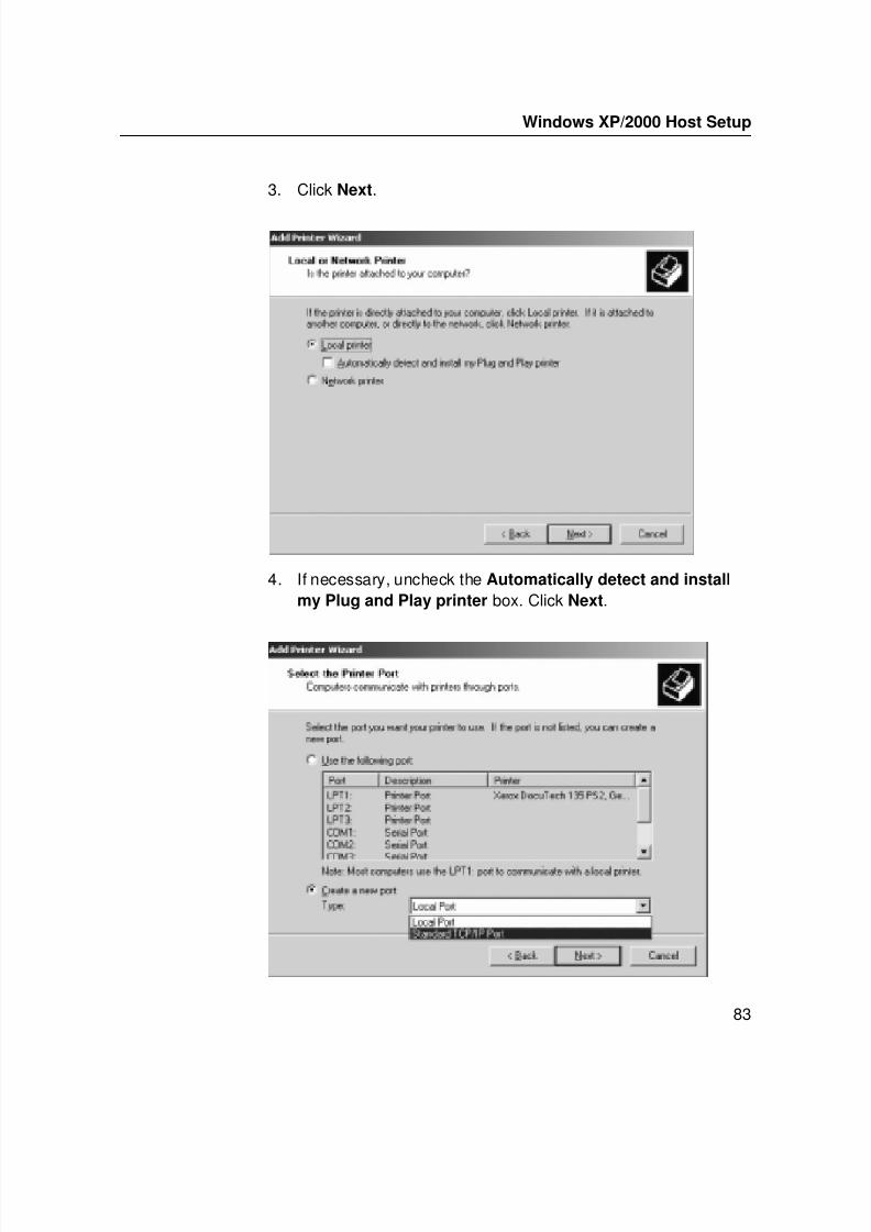
7/23/2019 54458302 IBM 6400
http://slidepdf.com/reader/full/54458302-ibm-6400 85/349
Windows XP/2000 Host Setup
83
3. Click Next.
4. If necessary, uncheck the Automatically detect and install
my Plug and Play printer box. Click Next.
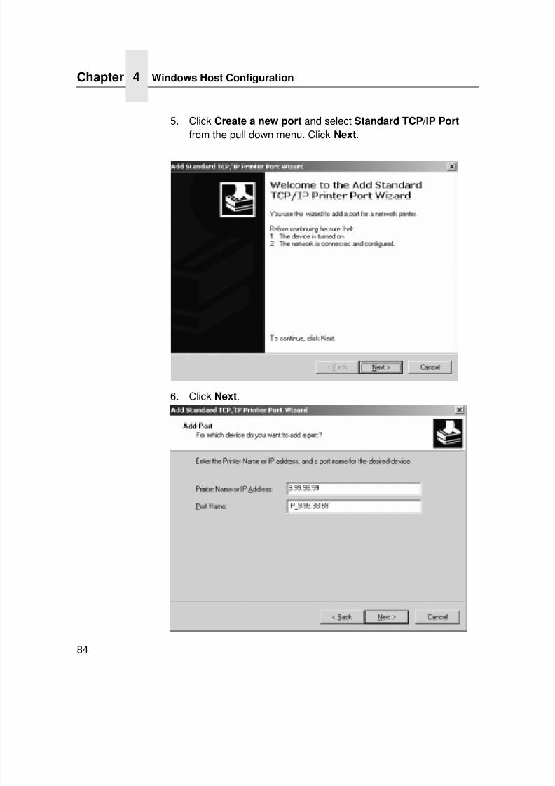
7/23/2019 54458302 IBM 6400
http://slidepdf.com/reader/full/54458302-ibm-6400 86/349
Chapter 4 Windows Host Configuration
84
5. Click Create a new port and select Standard TCP/IP Port
from the pull down menu. Click Next.
6. Click Next.
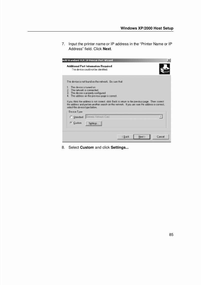
7/23/2019 54458302 IBM 6400
http://slidepdf.com/reader/full/54458302-ibm-6400 87/349
Windows XP/2000 Host Setup
85
7. Input the printer name or IP address in the “Printer Name or IP
Address” field. Click Next.
8. Select Custom and click Settings...
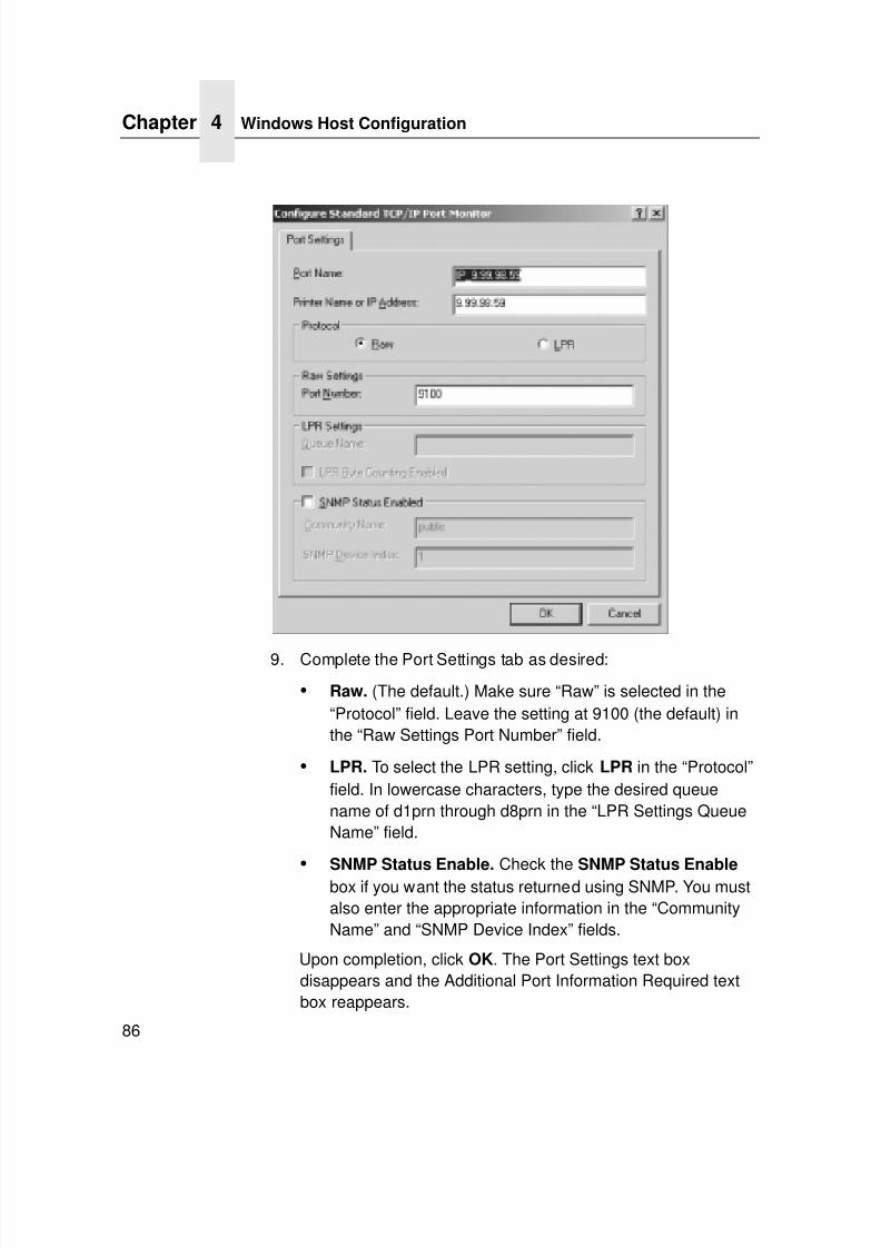
7/23/2019 54458302 IBM 6400
http://slidepdf.com/reader/full/54458302-ibm-6400 88/349
Chapter 4 Windows Host Configuration
86
9. Complete the Port Settings tab as desired:
• Raw. (The default.) Make sure “Raw” is selected in the“Protocol” field. Leave the setting at 9100 (the default) inthe “Raw Settings Port Number” field.
• LPR. To select the LPR setting, click LPR in the “Protocol”field. In lowercase characters, type the desired queuename of d1prn through d8prn in the “LPR Settings QueueName” field.
• SNMP Status Enable. Check the SNMP Status Enable box if you want the status returned using SNMP. You mustalso enter the appropriate information in the “CommunityName” and “SNMP Device Index” fields.
Upon completion, click OK. The Port Settings text boxdisappears and the Additional Port Information Required textbox reappears.
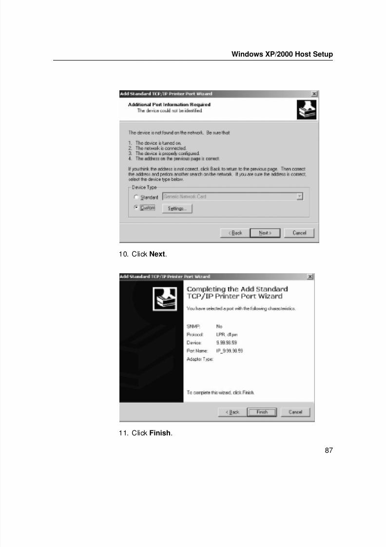
7/23/2019 54458302 IBM 6400
http://slidepdf.com/reader/full/54458302-ibm-6400 89/349
Windows XP/2000 Host Setup
87
10. Click Next.
11. Click Finish.
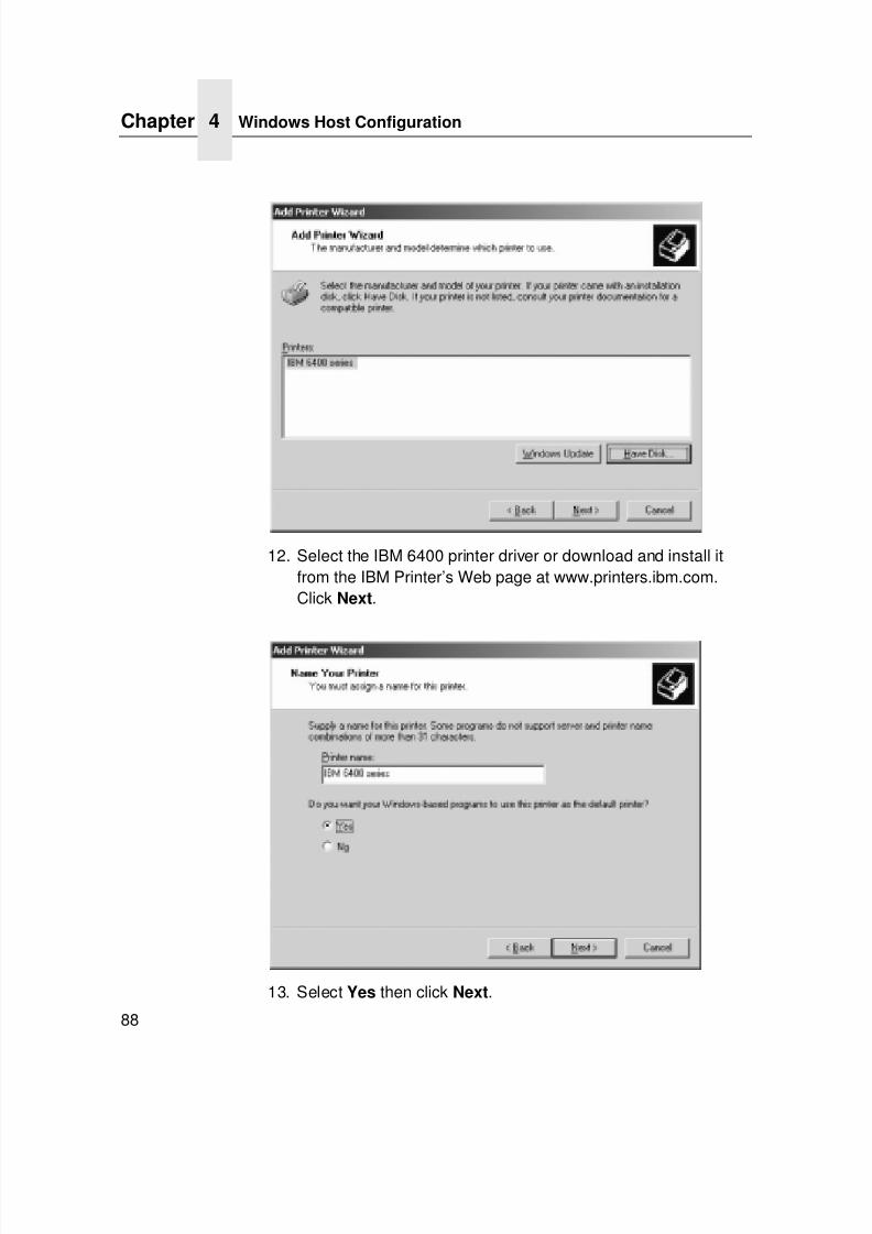
7/23/2019 54458302 IBM 6400
http://slidepdf.com/reader/full/54458302-ibm-6400 90/349
Chapter 4 Windows Host Configuration
88
12. Select the IBM 6400 printer driver or download and install itfrom the IBM Printer’s Web page at www.printers.ibm.com.Click Next.
13. Select Yes then click Next.
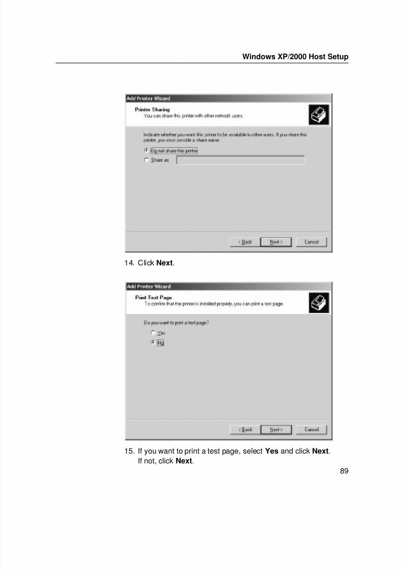
7/23/2019 54458302 IBM 6400
http://slidepdf.com/reader/full/54458302-ibm-6400 91/349
Windows XP/2000 Host Setup
89
14. Click Next.
15. If you want to print a test page, select Yes and click Next.If not, click Next.
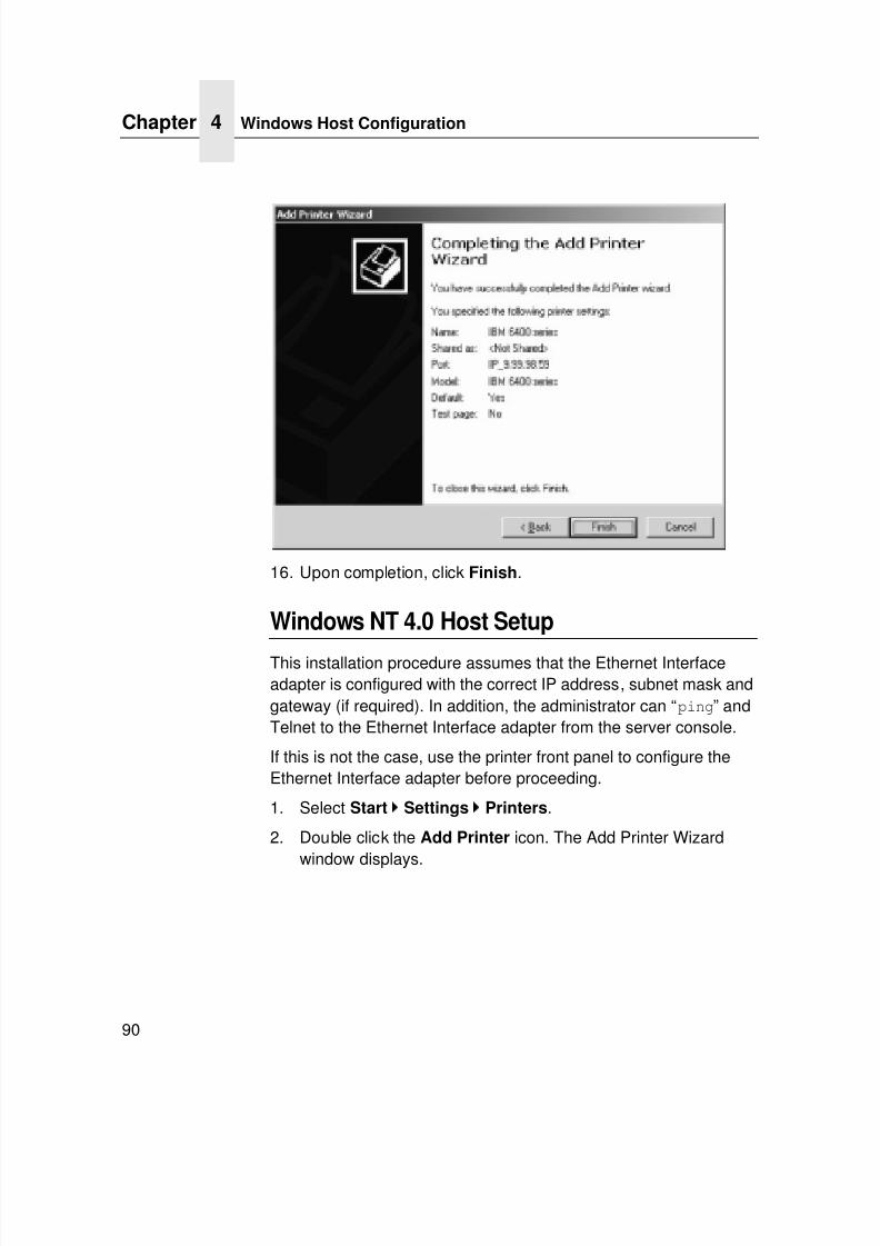
7/23/2019 54458302 IBM 6400
http://slidepdf.com/reader/full/54458302-ibm-6400 92/349
Chapter 4 Windows Host Configuration
90
16. Upon completion, click Finish.
Windows NT 4.0 Host Setup
This installation procedure assumes that the Ethernet Interfaceadapter is configured with the correct IP address, subnet mask andgateway (if required). In addition, the administrator can “ping” andTelnet to the Ethernet Interface adapter from the server console.
If this is not the case, use the printer front panel to configure theEthernet Interface adapter before proceeding.
1. Select Start
Settings
Printers.
2. Double click the Add Printer icon. The Add Printer Wizardwindow displays.
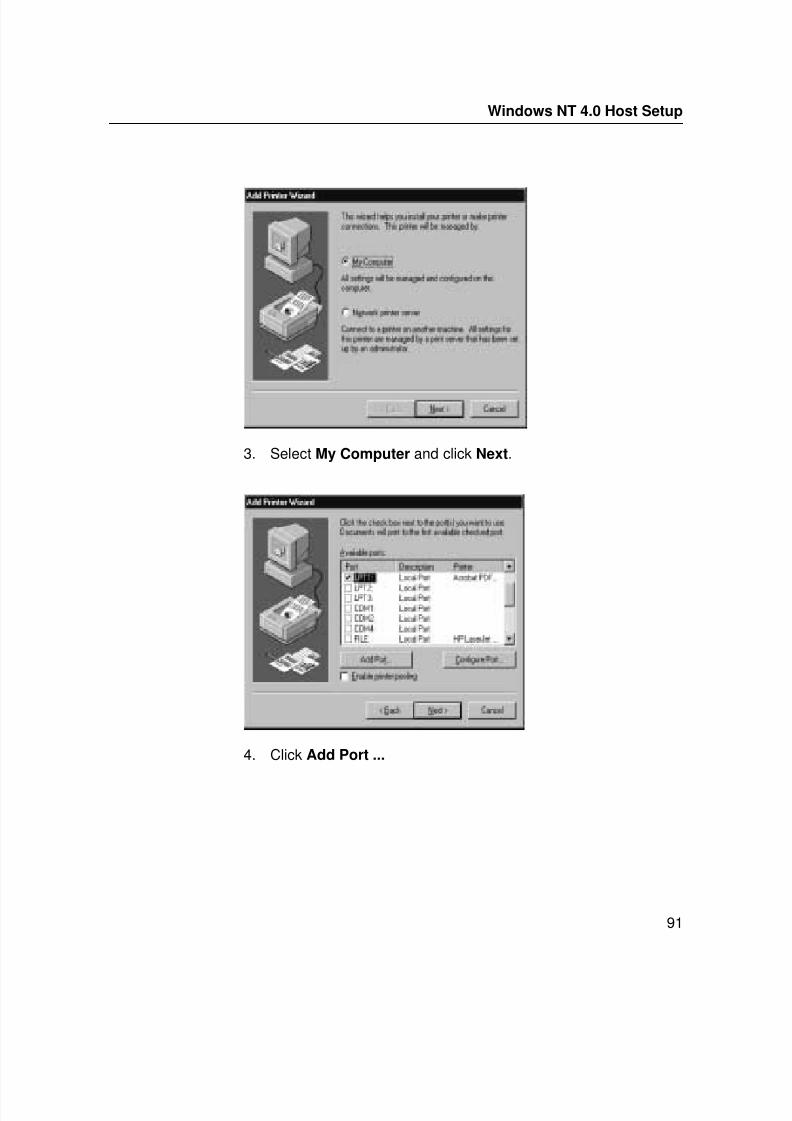
7/23/2019 54458302 IBM 6400
http://slidepdf.com/reader/full/54458302-ibm-6400 93/349
Windows NT 4.0 Host Setup
91
3. Select My Computer and click Next.
4. Click Add Port ...
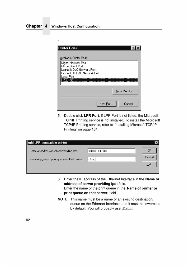
7/23/2019 54458302 IBM 6400
http://slidepdf.com/reader/full/54458302-ibm-6400 94/349
Chapter 4 Windows Host Configuration
92
”
5. Double click LPR Port. If LPR Port is not listed, the MicrosoftTCP/IP Printing service is not installed. To install the MicrosoftTCP/IP Printing service, refer to “Installing Microsoft TCP/IPPrinting” on page 104.
6. Enter the IP address of the Ethernet Interface in the Name or
address of server providing lpd: field.Enter the name of the print queue in the Name of printer or
print queue on that server: field.
NOTE: This name must be a name of an existing destination/ queue on the Ethernet Interface, and it must be lowercaseby default. You will probably use d1prn.
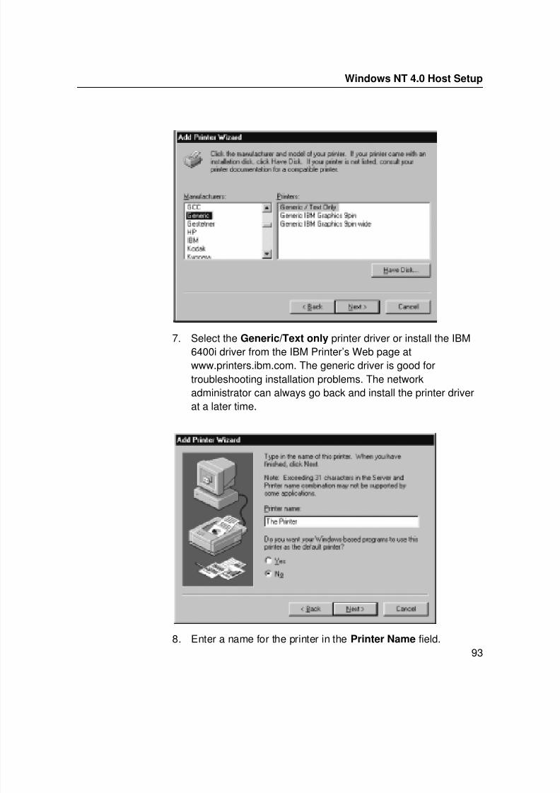
7/23/2019 54458302 IBM 6400
http://slidepdf.com/reader/full/54458302-ibm-6400 95/349
Windows NT 4.0 Host Setup
93
7. Select the Generic/Text only printer driver or install the IBM6400i driver from the IBM Printer’s Web page atwww.printers.ibm.com. The generic driver is good fortroubleshooting installation problems. The networkadministrator can always go back and install the printer driverat a later time.
8. Enter a name for the printer in the Printer Name field.
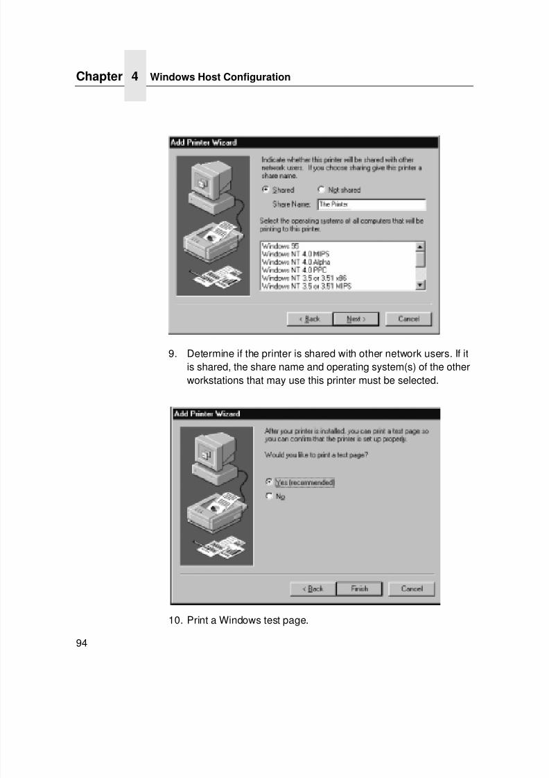
7/23/2019 54458302 IBM 6400
http://slidepdf.com/reader/full/54458302-ibm-6400 96/349
Chapter 4 Windows Host Configuration
94
9. Determine if the printer is shared with other network users. If itis shared, the share name and operating system(s) of the otherworkstations that may use this printer must be selected.
10. Print a Windows test page.
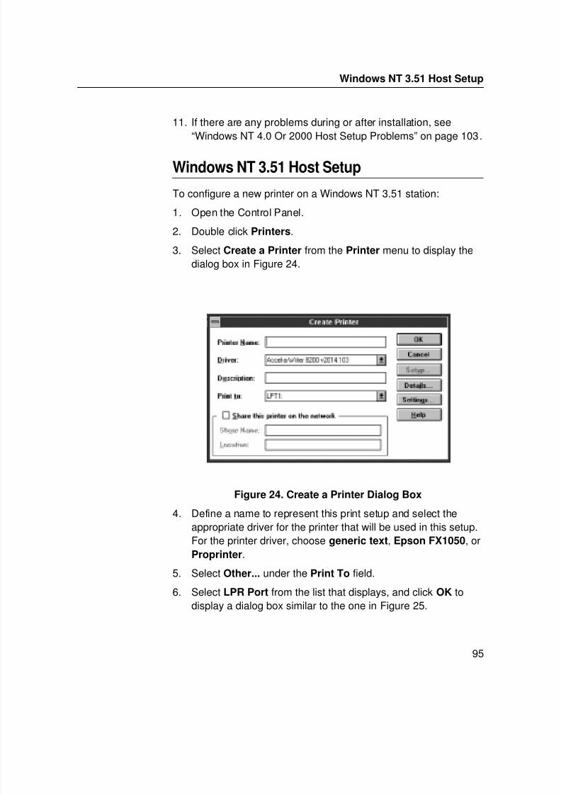
7/23/2019 54458302 IBM 6400
http://slidepdf.com/reader/full/54458302-ibm-6400 97/349
Windows NT 3.51 Host Setup
95
11. If there are any problems during or after installation, see
“Windows NT 4.0 Or 2000 Host Setup Problems” on page 103.
Windows NT 3.51 Host Setup
To configure a new printer on a Windows NT 3.51 station:
1. Open the Control Panel.
2. Double click Printers.
3. Select Create a Printer from the Printer menu to display thedialog box in Figure 24.
Figure 24. Create a Printer Dialog Box
4. Define a name to represent this print setup and select theappropriate driver for the printer that will be used in this setup.For the printer driver, choose generic text, Epson FX1050, or
Proprinter.5. Select Other... under the Print To field.
6. Select LPR Port from the list that displays, and click OK todisplay a dialog box similar to the one in Figure 25.
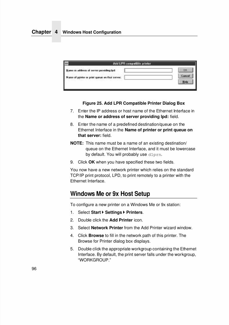
7/23/2019 54458302 IBM 6400
http://slidepdf.com/reader/full/54458302-ibm-6400 98/349
Chapter 4 Windows Host Configuration
96
Figure 25. Add LPR Compatible Printer Dialog Box
7. Enter the IP address or host name of the Ethernet Interface inthe Name or address of server providing lpd: field.
8. Enter the name of a predefined destination/queue on theEthernet Interface in the Name of printer or print queue on
that server: field.
NOTE: This name must be a name of an existing destination/ queue on the Ethernet Interface, and it must be lowercaseby default. You will probably use d1prn.
9. Click OK when you have specified these two fields.
You now have a new network printer which relies on the standardTCP/IP print protocol, LPD, to print remotely to a printer with theEthernet Interface.
Windows Me or 9x Host Setup
To configure a new printer on a Windows Me or 9x station:
1. Select Start
Settings
Printers.
2. Double click the Add Printer icon.
3. Select Network Printer from the Add Printer wizard window.
4. Click Browse to fill in the network path of this printer. TheBrowse for Printer dialog box displays.
5. Double click the appropriate workgroup containing the EthernetInterface. By default, the print server falls under the workgroup,“WORKGROUP.”
7/23/2019 54458302 IBM 6400
http://slidepdf.com/reader/full/54458302-ibm-6400 99/349
Windows Me or 9x Host Setup
97
6. Continue searching the network until you see the Ethernet
Interface name, “P_xxxxxx” or “M_xxxxxx”, where “xxxxxx”equals the last six digits of the print server Ethernet addressfound when a configuration is printed.
7. Once you see the Ethernet Interface, double click it to display alist of predefined destinations/queues from which to choose.
8. Select a destination/queue that will use d1prn.
9. Click OK once you have selected a destination. The networkpath window reappears with the path filled in.
10. Click Next.
11. Select the appropriate print driver and click Next.
12. Fill in a name for this new network printer at the next windowand decide if you want this to be the default printer. This printername can be anything you would like as long as it is unique.
13. When prompted for a test page, select either Yes or No depending on the state of the attached printer, and click Finish.
NOTE: Windows may ask for a disk or CD-ROM to load theappropriate printer driver to complete this new printer
setup.There should now be a new printer icon within the “Printers” folder.This new network printer relies on NetBIOS over TCP/IP as theunderlying protocol to print to the Ethernet Interface.
7/23/2019 54458302 IBM 6400
http://slidepdf.com/reader/full/54458302-ibm-6400 100/349
Chapter 4 Windows Troubleshooting Tips
98
Windows Troubleshooting Tips
This section provides information on possible solutions to somestandard Windows and Ethernet Interface configuration errors.
Technical Support
If you require technical support, please have the followinginformation available when you call:
1. Level of software are you running.
2. Type of attachment do you have.
3. Your host operating system.
4. A detailed description of the problem.
5. How often, and when the problem occurs
6. A detailed description of your network and the componentsattached.
Ethernet Interface Cannot Be Found On The
NetworkPlease follow these tips to determine what the problem may be withyour Ethernet Interface configuration.
• Have you assigned the Ethernet Interface a unique and valid IPaddress which corresponds with the other IP addresses onyour network? For example, are you sure no other device isusing this IP address?
• Are you sure you are trying to talk to the Ethernet Interfacefrom a Windows station on the same subnet? The print servercan only be seen locally unless you configured a routing entryearlier.
7/23/2019 54458302 IBM 6400
http://slidepdf.com/reader/full/54458302-ibm-6400 101/349
HTML Configuration Forms Will Not Display
99
• If you look at the back of the printer, is the STAT LED flashing
once a second, or is it quicker than that? A slower, once-a-second rate indicates that the print server is in fact configuredwith an IP address. A faster rate means it knows nothing aboutthis, so you may need to try the configuration process again.
• Have you confirmed that the network connection to theEthernet Interface is working correctly? Trying different networkcables and locations will help narrow down the problem.
• For wireless NIC, is the SSID correct? Is the operation modecorrect?
HTML Configuration Forms Will Not Display
• Can you ping the Ethernet Interface from the Windowsstation? If not, refer to “Ethernet Interface Cannot Be Found OnThe Network” on page 98.
• Have you used the correct URL for the Ethernet Interface homepage? It should behttp://EthernetInterfaceIPaddress (e.g., http://192.75.11.9).
• Is HTTP support enabled? If not, refer to “Web Browser/HTTPProblem” on page 103.
Errors Occur When Defining An LPR Printer
• Can you ping the Ethernet Interface from your Windows NTstation? If not, please refer to “Ethernet Interface Cannot BeFound On The Network” on page 98.
• Did you specify the correct IP address or host name for the
Ethernet Interface in the first field of the “Add LPR CompatiblePrinter” box?
• Did you specify a valid destination/queue on the EthernetInterface in the second field of the “Add LPR CompatiblePrinter” dialogue box? If so, did you also enter it in lowercaseletters?
7/23/2019 54458302 IBM 6400
http://slidepdf.com/reader/full/54458302-ibm-6400 102/349
Chapter 4 Windows Troubleshooting Tips
100
Cannot Browse The Ethernet Interface On The
Network
• Have you looked under the right Windows workgroup? Bydefault, the Ethernet Interface will be found under“WORKGROUP.”
• Are you able to browse other Windows stations and devices onthe network from this same station?
• Has this Windows station been given enough time to update itsregistry so it can see this newly added workgroup device?
Sometimes Windows stations can take considerable time,depending on the size of the network.
Printer Errors When Printing Or No Output
• Is there a large job currently printing which is taking up all of theprinter resources? Usually when printing from Windows 95/98stations, a busy printer can cause Windows to display a printererror message. This is because it demands immediate printerattention rather than holding the data until the printer is ready
again. The best way around this is to use a central spoolingstation like an NT server.
• Have you tried restarting the spooler under “ControlPanel:Services?” Sometimes this is needed to get printingstarted.
NOTE: As a last resort, you may want to reboot the Windowsstation. Sometimes this is the only option to completelyclear this situation. The Ethernet Interface usually hasnothing to do with this problem.
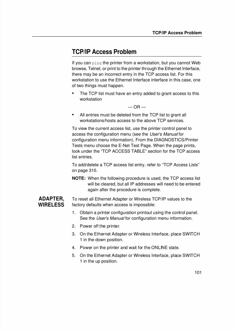
7/23/2019 54458302 IBM 6400
http://slidepdf.com/reader/full/54458302-ibm-6400 103/349
TCP/IP Access Problem
101
TCP/IP Access Problem
If you can ping the printer from a workstation, but you cannot Webbrowse, Telnet, or print to the printer through the Ethernet Interface,there may be an incorrect entry in the TCP access list. For thisworkstation to use the Ethernet Interface interface in this case, oneof two things must happen.
• The TCP list must have an entry added to grant access to thisworkstation
— OR —
• All entries must be deleted from the TCP list to grant allworkstations/hosts access to the above TCP services.
To view the current access list, use the printer control panel toaccess the configuration menu (see the User's Manual forconfiguration menu information). From the DIAGNOSTICS/PrinterTests menu choose the E-Net Test Page. When the page prints,look under the “TCP ACCESS TABLE” section for the TCP accesslist entries.
To add/delete a TCP access list entry, refer to “TCP Access Lists”on page 310.
NOTE: When the following procedure is used, the TCP access listwill be cleared, but all IP addresses will need to be enteredagain after the procedure is complete.
ADAPTER,WIRELESS
To reset all Ethernet Adapter or Wireless TCP/IP values to thefactory defaults when access is impossible:
1. Obtain a printer configuration printout using the control panel.See the User's Manual for configuration menu information.
2. Power off the printer.
3. On the Ethernet Adapter or Wireless Interface, place SWITCH1 in the down position.
4. Power on the printer and wait for the ONLINE state.
5. On the Ethernet Adapter or Wireless Interface, place SWITCH1 in the up position.
7/23/2019 54458302 IBM 6400
http://slidepdf.com/reader/full/54458302-ibm-6400 104/349
Chapter 4 Windows Troubleshooting Tips
102
6. From a workstation attached to this network segment, create
an ARP entry. The Ethernet Interface IP address and hardwareor Machine Address Code (MAC) address are needed. At theworkstation enter:
arp -s <ipaddress> < MACaddress>
ping <ipaddress>
7. Try to ping this IP address to see if the Ethernet Interface canbe seen on your network. If the interface does not respond,verify you are on the same network segment as the printer andthat the ARP entry was created.
8. Telnet into the Ethernet Interface using the same IP addressas above. Log in as root. There is no password by default.
9. At the system prompt, enter:
store tcpip from default
config http on
save
reset
NOTE: This will reset all TCP/IP settings to factory default andreset the Ethernet Interface.
10. Power the printer off and then back on.
11. Set the IP address, subnet mask, and default gatewayparameters to the desired values.
INTEGRATED To reset all Integrated Ethernet Interface TCP/IP values to thefactory defaults when access is impossible, contact your IBMservice representative for assistance.
7/23/2019 54458302 IBM 6400
http://slidepdf.com/reader/full/54458302-ibm-6400 105/349
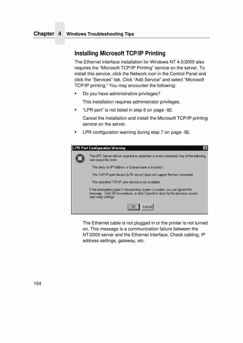
7/23/2019 54458302 IBM 6400
http://slidepdf.com/reader/full/54458302-ibm-6400 106/349
Chapter 4 Windows Troubleshooting Tips
104
Installing Microsoft TCP/IP Printing
The Ethernet Interface installation for Windows NT 4.0/2000 alsorequires the “Microsoft TCP/IP Printing” service on the server. Toinstall this service, click the Network icon in the Control Panel andclick the “Services” tab. Click “Add Service” and select “MicrosoftTCP/IP printing.” You may encounter the following:
• Do you have administrative privileges?
This installation requires administrator privileges.
• “LPR port” is not listed in step 6 on page -92.
Cancel the installation and install the Microsoft TCP/IP printingservice on the server.
• LPR configuration warning during step 7 on page -92.
The Ethernet cable is not plugged in or the printer is not turnedon. This message is a communication failure between theNT/2000 server and the Ethernet Interface. Check cabling, IP
address settings, gateway, etc.
7/23/2019 54458302 IBM 6400
http://slidepdf.com/reader/full/54458302-ibm-6400 107/349
Windows NT 4.0 Or 2000 Host Setup Problems
105
• Test page does not print or prints incorrectly:
1.Is the printer online? Re-send test page.
2.The print queue name in step 6 on page -92 should be d1prn;however, the name can be changed. To verify the queuenames, print an E-Net Test Page. Refer to your User's
Manual for information.
3.The IBM NT print driver requires P-Series emulation active onthe printer. The Generic/Text driver should print in anyprinter emulation.
4.Delete then re-install the Microsoft TCP/IP Print service on
the server.
If you are still experiencing difficulty accessing or browsing theprinter, contact an IBM representative for further assistance.

7/23/2019 54458302 IBM 6400
http://slidepdf.com/reader/full/54458302-ibm-6400 108/349
Chapter 4 Windows Troubleshooting Tips
106
7/23/2019 54458302 IBM 6400
http://slidepdf.com/reader/full/54458302-ibm-6400 109/349
107
5 AIX/UnixConfiguration
OverviewThis chapter details a complete Unix setup including:
• Configuring the Ethernet Interface with its mandatory TCP/IPsettings (e.g., IP address and subnet mask).
• Configuring the Unix host station with a new printer.
Unix Environment Description
The Ethernet Interface supports network printing under variousTCP/IP environments including all variations of Unix. Printing cancome from multiple hosts directly or through central spoolingmachines.
7/23/2019 54458302 IBM 6400
http://slidepdf.com/reader/full/54458302-ibm-6400 110/349
Chapter 5 Unix Ethernet Interface Configuration
108
Unix Ethernet Interface Configuration
There are mandatory and optional settings needed before the printserver can be detected on the network. This section offersalternative methods for configuring your Ethernet Interface andmentions some of the more common optional settings available.
Mandatory
Since TCP/IP is used, the Ethernet Interface must be configuredwith a minimum of an IP address and subnet mask before it can beseen on the network. To configure these options, see“Configuration Tools” on page 28.
Optional
Additional settings, like routing entries, can be configured allowingfor communication across subnets.
Configuration of the Ethernet Interface can be done from the controlpanel through host commands via Telnet or through the Web
browser interface. To configure these options, see “ConfigurationTools” on page 28.
Using ARP
To configure the Ethernet Interface with its TCP/IP settings using amanual arp command, the syntax is:
arp -s ipaddress ethernetaddress
For the aix command, the syntax is:
aix -s ether ipaddress Mac_address
To use either of these commands:
1. Log on to a Unix station as superuser or root. This stationmust be located on the same subnet as the Ethernet Interfacesince ARP is limited to subnets.
7/23/2019 54458302 IBM 6400
http://slidepdf.com/reader/full/54458302-ibm-6400 111/349
Using ARP
109
2. Find the Ethernet address for the Ethernet Interface by printing
a configuration or reading it from the control panel. It must beentered as part of this procedure.
3. Use the arp command to add an entry into the Unix stationARP table for this Ethernet Interface. Here is the most commonsyntax for this command:
arp -s ipaddress ethernetaddress
Example for Microsoft TCP stacks:
arp -s 192.75.11.9 00:80:72:07:00:60
This example specifies an Ethernet Interface using IP address
192.75.11.9 and Ethernet address 00:80:72:07:00:60.4. Verify that the ARP entry was properly applied.
arp -a
You should see an entry in the listed ARP table with the IPaddress and Ethernet address specified in step 3.
5. Try to ping this IP address to see if the Ethernet Interface canbe seen on your network.
At this point, you should be able to communicate with the EthernetInterface from your local Unix station. This means the printer knows
about an IP address and subnet mask and has these settings in itscurrent memory. However, if the Ethernet Interface is shut off,these settings will be lost unless you store them in flash memory,as follows:
1. Start a Web browser on your local station and direct it to theURL:http://EthernetInterfaceIPaddress/
networkConf.html
(e.g., http://192.75.11.9/networkConf.html).
NOTE: If prompted for a “User ID” and password first, type inroot for the ID and press ENTER at the password prompt(since there is no default password).
2. At the “Network Configuration” HTML form that displays, click inthe field below the “IP Address” heading and type in the IPaddress for the Ethernet Interface.
7/23/2019 54458302 IBM 6400
http://slidepdf.com/reader/full/54458302-ibm-6400 112/349
Chapter 5 Unix Ethernet Interface Configuration
110
3. Under the “Subnet Mask” heading, enter the Ethernet Interface
subnet mask.NOTE: If you would like to communicate with the Ethernet
Interface from across routers, you will need to fill in an entrywithin the “Routing” section. Please see “CommunicatingAcross Routers” on page 112 for further details.
4. Click on the SUBMIT button when done and physically repowerthe print server to make sure the new settings are in effect.
Using RARP
RARP allows you to dynamically assign an IP address to theEthernet Interface upon bootup. To configure the Ethernet Interfacewith its TCP/IP settings using RARP:
1. On your RARP server, make an entry in the /etc/ethers file forthe Ethernet Interface.
Syntax:
ethernetaddress EthernetInterfaceIPaddress
Example:
00:80:72:07:00:60 192.75.11.92. Start the RARP daemon on the RARP server if not already
running. If it is running, send an HUP signal to it with the kill command:
Syntax:
kill -HUP pid
where pid is the process ID of the RARP daemon.
3. Power on the Ethernet Interface so that it immediately sendsout an RARP request. Wait one minute to allow the address
assignment process to complete. You should see the STATLED on the Ethernet Interface slow down, to indicate that itknows about an IP address to use.
7/23/2019 54458302 IBM 6400
http://slidepdf.com/reader/full/54458302-ibm-6400 113/349
Using BOOTP
111
4. Try to ping the Ethernet Interface IP address from a local Unix
station to see if it can be seen on your network.NOTE: You will only be able to communicate with the Ethernet
Interface from a network station on the same subnet as theprint server. The Ethernet Interface needs to be told abouta default router/gateway so any packets that come in froma different subnet can be returned via this gateway. Pleasesee “Communicating Across Routers” on page 112 to setthis up.
Using BOOTP
BOOTP allows you to dynamically assign an IP address to theEthernet Interface upon bootup. In addition, the BOOTP server canprovide additional details like a default router/gateway address. Toconfigure the Ethernet Interface with its TCP/IP settings usingBOOTP:
1. On your BOOTP server, make an entry in the /etc/bootptab filefor the Ethernet Interface.
Syntax:
EthernetInterfaceIPname:\:sm=netmask :\:hd=homedirectory :\:bf=null:\:gw=defaultgateway :\:ht=ethernet:\:ha=ethernetaddress:\:ip=ipaddress:\:ts=timeserver :\:to=timezone:
Example:
spike:\
:sm=255.255.255.0:\:hd=/usr/null:\:bf=null:\:gw=192.75.11.1:\:ht=ethernet:\:ha=008072070060:\:ip=192.75.11.9:\:ts=192.75.11.7:\:to=25200:
7/23/2019 54458302 IBM 6400
http://slidepdf.com/reader/full/54458302-ibm-6400 114/349
Chapter 5 Unix Ethernet Interface Configuration
112
2. Turn the Ethernet Interface on so that it immediately sends out
a BOOTP request. Wait one minute to allow the IP addressassignment process to complete. You should see the STATLED (on the Ethernet Interface) slow down, indicating it knowsabout an IP address to use.
3. Try to ping the Ethernet Interface IP address from a networkstation to see if it can be seen on your network.
NOTE: You will be able to communicate with the Ethernet Interfacefrom network stations on different subnets if the print serverhas been told about its default router/gateway in theBOOTP response from the BOOTP server.
Communicating Across Routers
Since Unix environments rely on TCP/IP to communicate with theEthernet Interface, crossing routers becomes an issue.
After you have followed one of the Ethernet Interface configurationmethods mentioned (other than the BOOTP method), most likely,you will only be able to communicate with the print server from thesame subnet. This means any host across a router will not be able
to see your Ethernet Interface. To communicate across a router,store a default router/gateway within the print server so that anypackets destined for another subnet get forwarded to this routerautomatically. The router (or series of routers) can then take overthe process of ensuring the packets get to their final destination onanother subnet on your network.
To configure a default router/gateway within the Ethernet Interface:
1. Start a Web browser on your local station and direct it to theURL:http://EthernetInterfaceIPaddress/
networkConf.html
(e.g., http://192.75.11.9/networkConf.html).
NOTE: If prompted for a “User ID” and password first, type in root for the ID and press ENTER at the password prompt (sincethere is no default password).
7/23/2019 54458302 IBM 6400
http://slidepdf.com/reader/full/54458302-ibm-6400 115/349
Manual System V Host Setup
113
2. At the “Network Configuration” HTML form that displays, click in
the first field below the “Gateway” heading and type in the IPaddress of the default router/gateway for the Ethernet Interfacesubnet.
3. Click the SUBMIT button when done and physically repowerthe print server to make sure the new setting is in effect.
Unix Host Configuration
There may be times when you would prefer or need to perform the
manual setup steps for a new printer definition. There may also betimes when you require a less common print solution such as directsocket capabilities. This section covers these additional setups.
Manual System V Host Setup
This setup involves any Unix operating system using System Vprint spooling (e.g., SCO, Solaris ® , HP-UX ® , DG/UX® , etc.). Thismeans an interface file is used for each defined printer and, in thecase of any System V print setup involving an Ethernet Interface,
the RSHD protocol is used to transfer data from the host to the printserver.
To manually configure a new System V printer on a Unix station,create a dummy device file that acts as a locking mechanismbetween contending print jobs.
Syntax:
touch /dev/EthernetInterfacename.portname
where EthernetInterfacename is the host or IP name of the printserver and portname is one of its four I/O ports.
Example:
touch /dev/spike.prn
7/23/2019 54458302 IBM 6400
http://slidepdf.com/reader/full/54458302-ibm-6400 116/349
7/23/2019 54458302 IBM 6400
http://slidepdf.com/reader/full/54458302-ibm-6400 117/349
Printing With FTP
115
3. Create the log and account files specified by the lf= and af=
entries in the printcap entry for this printer.Example:
touch /usr/spool/lpd/6400i/log
touch /usr/spool/lpd/6400i/acct
4. Change permissions and ownership on the spool directory andeverything within it.
Example:
chmod -R g+rwX,o+rX /usr/spool/lpd/ 6400i
chmod -R daemon.daemon /usr/spool/lpd/ 6400i
5. Start the printer daemon for this new printer.
Example:
lpc start 6400i
You now have a new printer which relies on LPR/LPD to print to aEthernet Interface printer. Use the following command to testprinting:
Syntax:
lpr -P printername filename
Example:lpr -P 6400i /etc/hosts
Printing With FTP
Print jobs can also be sent to the Ethernet Interface using the FileTransfer Protocol (FTP). To do this:
1. On your network station, change to the directory containing thefile you want to print.
2. Open an FTP session with the Ethernet Interface.
Syntax:
ftp EthernetInterfaceIPaddress
3. Log in as root.
4. At the password prompt, press ENTER (since there is nodefault password).
7/23/2019 54458302 IBM 6400
http://slidepdf.com/reader/full/54458302-ibm-6400 118/349
Chapter 5 Unix Host Configuration
116
5. Change to the dest directory.
Syntax:cd dest
6. List the contents of this directory using the dir command anddetermine which destination/queue you would like to send theprint job through. Most likely, you will select d1prn for the PRNport.
7. Change to this destination directory.
Example:
cd d1prn
8. Change the mode to correspond with the type of file you aregoing to print. By default, ASCII is set for text-only files, but ifyou need to print both text and graphics, select binary using thebin command.
9. Place the file to be printed within this directory on the EthernetInterface, so it can be spooled and printed.
Syntax:
put filename
10. Close the FTP session, unless you have more jobs to print.Syntax:
quit
7/23/2019 54458302 IBM 6400
http://slidepdf.com/reader/full/54458302-ibm-6400 119/349
Direct Socket Printing
117
Direct Socket Printing
Within TCP/IP environments, there are some setups which requirethe host to print directly to a TCP port number on the EthernetInterface, bypassing all of the higher level destination/queuenames. If you run into a setup which requires this, you will need todefine two parameters for a new print setup:
1. Ethernet Interface IP address. The IP address or host nameof the print server to which you want to print.
2. Ethernet Interface TCP port number. A pre-defined numberfor the I/O port on the print server. 9100 is the default portnumber.
Though the host will be sending directly to a TCP port number onthe Ethernet Interface, the port numbers are still mapped todestinations/queues in case there is some type of specialprocessing or logging to be done to the job. However, thedestination name is of no concern in this type of printer definition.Only the two parameters mentioned above need to be defined forprinting to work.
Printing From AIX
Version 4.0 and higher of AIX ® offers LPR/LPD support for networkprinting. This means, to set up a new printer under this operatingsystem, you only need to define these two parameters:
1. Ethernet Interface IP address. The IP address or host nameof the print server to which you want to print.
2. Ethernet Interface destination/queue. A pre-defined nameon the print server telling the device to which I/O port to send
the jobs. Most likely, you will use d1prn for the PRN.
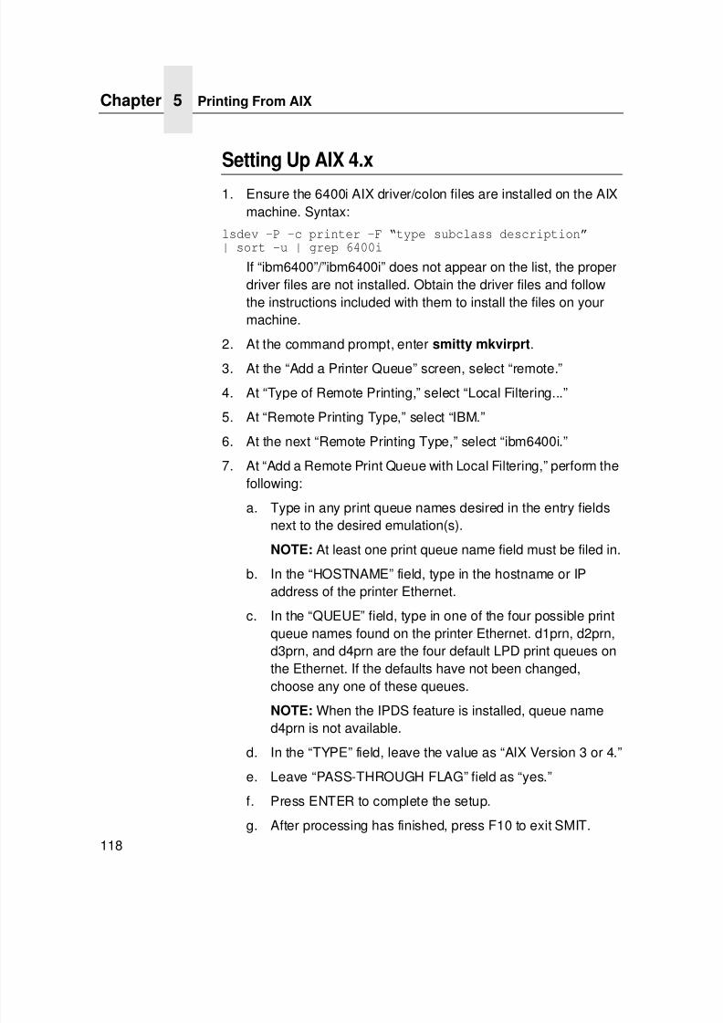
7/23/2019 54458302 IBM 6400
http://slidepdf.com/reader/full/54458302-ibm-6400 120/349
Chapter 5 Printing From AIX
118
Setting Up AIX 4.x
1. Ensure the 6400i AIX driver/colon files are installed on the AIXmachine. Syntax:
lsdev -P -c printer -F “type subclass description”| sort -u | grep 6400i
If “ibm6400”/”ibm6400i” does not appear on the list, the properdriver files are not installed. Obtain the driver files and followthe instructions included with them to install the files on yourmachine.
2. At the command prompt, enter smitty mkvirprt.
3. At the “Add a Printer Queue” screen, select “remote.”
4. At “Type of Remote Printing,” select “Local Filtering...”
5. At “Remote Printing Type,” select “IBM.”
6. At the next “Remote Printing Type,” select “ibm6400i.”
7. At “Add a Remote Print Queue with Local Filtering,” perform thefollowing:
a. Type in any print queue names desired in the entry fieldsnext to the desired emulation(s).
NOTE: At least one print queue name field must be filed in.
b. In the “HOSTNAME” field, type in the hostname or IPaddress of the printer Ethernet.
c. In the “QUEUE” field, type in one of the four possible printqueue names found on the printer Ethernet. d1prn, d2prn,d3prn, and d4prn are the four default LPD print queues onthe Ethernet. If the defaults have not been changed,choose any one of these queues.
NOTE: When the IPDS feature is installed, queue named4prn is not available.
d. In the “TYPE” field, leave the value as “AIX Version 3 or 4.”
e. Leave “PASS-THROUGH FLAG” field as “yes.”
f. Press ENTER to complete the setup.
g. After processing has finished, press F10 to exit SMIT.
7/23/2019 54458302 IBM 6400
http://slidepdf.com/reader/full/54458302-ibm-6400 121/349
Ethernet Interface Cannot Be Found On The Network
119
8. At the command prompt, enter eng -A to view the print queues
just entered.9. Enter qprt -Pqueuename filename to send a job to the
printer.
Unix Troubleshooting Tips
This section provides information on possible solutions to somestandard configuration errors. If you require technical support,please have as much of the following information available when
you call:1. Level of software are you running.
2. Type of attachment do you have.
3. Your host operating system.
4. How often, and when the problem occurs.
5. A detailed description of the problem.
6. A detailed description of your network and the componentsattached.
Ethernet Interface Cannot Be Found On TheNetwork
• Have you configured the Ethernet Interface with a unique andvalid IP address which corresponds with the other IP addresseson your network? For example, are you sure no other device isusing this IP address?
• Are you sure you are trying to talk to the Ethernet Interface
from a Unix station on the same subnet? Currently, the printserver can only be seen locally unless you configured it with arouting entry.
7/23/2019 54458302 IBM 6400
http://slidepdf.com/reader/full/54458302-ibm-6400 122/349
Chapter 5 Unix Troubleshooting Tips
120
• If you look at the back of the printer, is the STAT LED flashing
once a second or is it quicker than that? A slower, once-a-second rate tells you that the print server is in fact configuredwith an IP address. A faster rate indicates it knows nothingabout this, so you may need to try the configuration processagain.
• Have you confirmed that the network connection to theEthernet Interface is working correctly? Trying different networkcables and locations will help narrow down the problem.
Nothing Prints
• Can you ping the Ethernet Interface from your Unix station? Ifnot, please refer to “Ethernet Interface Cannot Be Found OnThe Network” shown above.
• Is the Ethernet Interface able to communicate with the attachedprinter? To test this, you can:
1.Telnet to the print server (e.g., telnet 192.75.11.9)and log in as root.
2.Enter the command start fox prn.
3.Execute stop prn right after starting the test.
4.This test will send the same text line over and over to theattached printer.
• Is the job getting stuck in the Unix host queue? If so, check thatthe printer is online. If it is, there is a configuration error on theUnix station, so creating a new print setup may be needed.
• Is the control panel showing any activity to indicate it isreceiving data? If so, but there is nothing printing, check if a
manual form feed is needed. Also, ensure that the printer cansupport the type of job coming through.
7/23/2019 54458302 IBM 6400
http://slidepdf.com/reader/full/54458302-ibm-6400 123/349
Stair-Stepped Output
121
• Do all jobs fail or just certain ones? For example, is it possible
that jobs from a certain application are the only ones to fail? Ifso, check the type of data it sends to make sure it matches theprinter emulation. Check the application printer configurationfor mistakes.
• If you are using System V, was the spooler restarted?
Stair-Stepped Output
Stair-stepped output is print which starts at the top left of the pagebut every line thereafter starts a little further over to the right. It also
refers to Unix jobs that print one line of text at the top of a pagefollowed by a series of blank pages.
This kind of output happens only with Unix text jobs if carriagereturn insertion is not incorporated into the print setup. The printermay be told to do a linefeed, but the Unix job does not specifyanything about a carriage return to follow this.
To fix this, carriage return insertion must be enabled somewhere inthe print setup. The easiest and most common location is on theEthernet Interface itself within the appropriate model. The feature is
called “onlcr” and the command syntax is:set model modelname stty onlcr
save
For example, if printing to the destination, d1prn, the associatedmodel is m1. Therefore, the command is:
set model m1 stty onlcr
save
7/23/2019 54458302 IBM 6400
http://slidepdf.com/reader/full/54458302-ibm-6400 124/349
Chapter 5 Unix Troubleshooting Tips
122
No Form Feed Or Extra Page Comes Out
Unix text jobs may also have problems outputting the last page of a job especially when the BSD Remote (LPD) print method is used.This means the form feed button has to be pressed on the printer toget this last page out.
To make this process automatic, tell the Ethernet Interface tohandle this task by setting this feature “on” in the appropriatemodel. The command syntax is:
set model modelname trailer $FF
save
For example, if printing to the destination, d2prn, the associatedmodel is m2. Therefore, the command is:
set model m2 trailer $FF
save
For default destination model mappings of the Ethernet Interface,please see “Ethernet Interface Naming Schemes” on page 314.
TCP/IP Access Problem
If you can ping the printer from a workstation, but you cannot Webbrowse, Telnet, or print to the printer through the Ethernet Interface,there may be an incorrect entry in the TCP access list. In order forthis workstation to use the Ethernet Interface in this case, one oftwo things must happen:
• the TCP list must have an entry added to grant access to thisworkstation, or
• all entries must be deleted from the TCP list to grant allworkstations/hosts access to the above TCP services.
To view the current access list, use the printer control panel toaccess the configuration menu (see the User's Manual forconfiguration menu information). From the DIAGNOSTICS/PrinterTests menu choose the E-NET Test Page. When the page prints,look under the “TCP ACCESS TABLE” section for the TCP accesslist entries.
7/23/2019 54458302 IBM 6400
http://slidepdf.com/reader/full/54458302-ibm-6400 125/349
TCP/IP Access Problem
123
To add/delete a TCP access list entry, refer to “TCP Access Lists”
on page 310.NOTE: When the following procedure is used, the TCP access list
will be cleared, but all IP addresses will need to be enteredagain after the procedure is complete.
ADAPTER,WIRELESS
To reset all Ethernet Adapter or Wireless TCP/IP values to thefactory defaults when access is impossible:
1. Obtain a configuration printout using the control panel. See theUser's Manual for configuration menu information.
2. Power off the printer.
3. On the Ethernet Adapter or Wireless Interface, place SWITCH1 in the down position.
4. Power on the printer and wait for the ONLINE state.
5. On the Ethernet Adapter or Wireless Interface, place SWITCH1 in the up position.
6. From a workstation attached to this network segment, createan ARP entry. The Ethernet Interface IP address and hardwareor Machine Address Code (MAC) address are needed. At the
workstation enter:arp -s <ipaddress> < MACaddress>
ping <ipaddress>
7. Try to ping this IP address to see if the Ethernet Interface canbe seen on your network. If the interface does not respond,verify you are on the same network segment as the printer andthat the ARP entry was created.
8. Telnet into the Ethernet Interface using the same IP addressas above. Log in as root with no password.
9. At the system prompt, enter:store tcpip from default
config http on
reset
NOTE: This will reset all TCP/IP settings to factory default andreset the Ethernet Interface.
7/23/2019 54458302 IBM 6400
http://slidepdf.com/reader/full/54458302-ibm-6400 126/349
Chapter 5 Unix Troubleshooting Tips
124
10. Power the printer off and then back on.
11. Set the IP address, subnet mask, and default gatewayparameters to the desired values.
12. If the Web browser access does not work, telnet into theEthernet Interface as root. Enter the following command:
config http on
INTEGRATED To reset all Integrated Ethernet Interface TCP/IP values to thefactory defaults when access is impossible, contact your IBMservice representative for assistance.
Front Panel Message - Dynamically Set ParamsRead Only
This is not an error. It is an informational message warning that theIP address has been dynamically set by dhcp, rarp, or bootp.
To assign a static IP address, turn off the rarp, bootp, and dhcp onthe adapter. Use the following procedure:
1. Telnet to the adapter. Login = root, password = (Enter key)
Telnet commands are:
store tcpip 1 opts -rarp -bootp -dhcp
reset
Wait two minutes for the adapter to reset.
2. Program the IP address, Subnet Mask, and Gateway (ifrequired) from the front panel.
7/23/2019 54458302 IBM 6400
http://slidepdf.com/reader/full/54458302-ibm-6400 127/349
125
6 Novell Configuration
Overview
NOTE: Novell configuration is not applicable to the integrated
Ethernet.
ADAPTER,WIRELESS
This chapter applies to the Ethernet Adapter and Wireless Interfaceand details a complete Novell setup, including:
• Identifying the Ethernet Interface on the network.
• Configuring the Ethernet Interface with its mandatory printsetup settings.
• Configuring a new print queue on the file server.
For information about additional options available with the 10/100
Base-T interface, see “Novell Configuration For 10/100Base-TInterfaces” on page 143.
NOTE: The NetWare 3.x PConsole procedures (page 128) usePConsole v3.75. The NetWare 4.x PConsole procedures(page 134) use PConsole v4.15.
Novell Environment Description
The Ethernet Interface supports network printing under Novell
environments by using IPX. It supports all 3.x versions of NetWare.Version 4.x and 5.x is supported under bindery emulation only.
7/23/2019 54458302 IBM 6400
http://slidepdf.com/reader/full/54458302-ibm-6400 128/349
Chapter 6 Novell Ethernet Interface Configuration
126
Novell Ethernet Interface Configuration
ADAPTER,WIRELESS
Mandatory
Under all Novell environments, the Ethernet Interface does notrequire any network settings to make it visible on the network.Simply plug it in to your network and power it on. However, with anew print queue setup on a Novell file server, there can bemandatory settings needed on the Ethernet Interface.
Optional
Additional settings are available to fine-tune the EthernetInterface’s Novell functionality. These options include:
• NDS Context. The NDS context in which the print server objectwas created. If you create the printer server object in a differentfile server object from the file server you logged into, then toensure the absolute path, you must activate the NDS context.
• NDS Tree. The NDS tree the print server object was created in.This is only needed if your environment uses more than oneNDS tree.
• Mode. The mode the Ethernet Interface will run in. This can beauto, bindery, or NDS. The default is auto so that the EthernetInterface can autosense which mode it should run in. See“NetWare Version 4.x and 5.x RPRINTER Setup” on page 137for information on what to do when using both bindery and NDSfile servers at the same time.
7/23/2019 54458302 IBM 6400
http://slidepdf.com/reader/full/54458302-ibm-6400 129/349
7/23/2019 54458302 IBM 6400
http://slidepdf.com/reader/full/54458302-ibm-6400 130/349
Chapter 6 Novell Host Configuration
128
3. At the “Administration Configuration” HTML form that displays,
highlight the field beside the “Name” heading and type in thenew name of the print server.
4. Click on the SUBMIT button when done and physically repowerthe printer to make the new setting take effect.
Novell Host Configuration
ADAPTER,WIRELESS
Under all versions of NetWare, both PSERVER and RPRINTERsetups are supported by the Ethernet Interface. Since a PSERVER
setup is the most common, you will find the necessary steps toconfigure the Ethernet Interface as a PSERVER shown first.Configuration for RPRINTER and NPRINTER setup follow thePSERVER information.
NOTE: In a NetWare environment the Ethernet Interface willservice only one of the four available printer objects (suchas d1prn); do not configure more than one printer objectfrom the printer. The Ethernet Interface cannot servicemultiple file servers at one time; do not configure multiplefile servers to access the printer.
NetWare Version 3.x PSERVER Setup
To configure a print queue on a NetWare 3.x network:
1. Log on to the Novell file server as supervisor.
2. Enter PCONSOLE.
3. Select “Print Queue Information” from the PCONSOLE MainMenu.
4. Press INSERT to add a new queue to the list of currentlydefined queues showing.
5. Type in the name of this new queue when prompted and pressENTER. This can be any name you would like.
6. Press ESCAPE to return to the Main Menu.
7. Select “Print Server Information” and press ENTER.
7/23/2019 54458302 IBM 6400
http://slidepdf.com/reader/full/54458302-ibm-6400 131/349
NetWare Version 3.x PSERVER Setup
129
8. Press INSERT when the list of existing print servers displays.
9. Type the name of the Ethernet Interface when prompted for aprint server name, and press ENTER when done. The default isM_xxxxxx, where xxxxxx represents the last six digits of theEthernet address found on the configuration printout or controlpanel settings under Ethernet Parameters, MAC address (e.g.,M_091C1A).
10. Back at the print server list, select this newly defined EthernetInterface and press ENTER.
11. Select “Print Server Configuration” from the menu that displays.
12. Select “Printer Configuration” from the next menu to display alist of configured printers.
13. Select the first item listed as “NOT INSTALLED” and pressENTER.
14. At the printer configuration window, type in the name for thisnew printer. The name must be one of the predefineddestinations/queues on the Ethernet Interface, normallyd1prn.
15. Go to the “Type” field and press ENTER to see the possible
choices.
16. Select “Defined Elsewhere” from this list.
17. When done, press ESCAPE and select “Yes” to save thechanges to this new printer.
18. Press ESCAPE again to return to the “Print ServerConfiguration” menu.
19. Select “Queues Serviced by Printer.”
20. Select this new printer from the printer list that displays and
press ENTER.21. At the empty queue list that displays, press INSERT.
22. Select the queue created in step 5 and press ENTER.
23. When prompted for the priority, press ENTER to select thedefault or select a priority.
7/23/2019 54458302 IBM 6400
http://slidepdf.com/reader/full/54458302-ibm-6400 132/349
Chapter 6 Novell Host Configuration
130
24. Press ESCAPE until back at the PCONSOLE Main Menu.
25. Repower the printer.
26. Wait two minutes and then select “Print Queue Information”from the PCONSOLE Main Menu.
27. Select this new queue from the menu that displays.
28. Select “Currently Attached Servers” to see which print server isservicing this queue.
At this point, the Ethernet Interface name (e.g., M_091C1A) shouldshow within this window. This means the Ethernet Interface knows
about this new Novell print queue it must service as a PSERVER.Therefore, it will poll this queue regularly looking for jobs to print.
NOTE: In a NetWare environment the Ethernet Interface willservice only one of the four available printer objects (suchas d1prn); do not configure more than one printer objectfrom the printer. The Ethernet Interface cannot servicemultiple file servers at one time; do not configure multiplefile servers to access the printer.
7/23/2019 54458302 IBM 6400
http://slidepdf.com/reader/full/54458302-ibm-6400 133/349
NetWare Version 3.x RPRINTER Setup
131
NetWare Version 3.x RPRINTER Setup
These steps are for Novell environments with Netware 3.x (orearlier) file servers.
To configure a new RPRINTER on a NetWare 3.x network:
1. Log in to the Ethernet Interface command shell, npsh, as root.
If you have TCP/IP available and this print server already hasan IP address stored within it, you can use the built-in HTMLconfiguration forms or a Telnet session. Please see“Configuration Tools” on page 28 for further details. If you have
only Novell available, you will need to use a PC, laptop, orterminal.
NOTE: If you use HTML configuration, you will need to go to the“Network Configuration” HTML form(i.e., http://IPaddress/networkConf.html;e.g., http://192.75.11.9/networkConf.html)and look under the “Novell” section. The settings in thefollowing step are found there. If using a Telnet session,you will need to manually execute the commands listed inthe next step.
2. Store the RPRINTER settings on the Ethernet Interface. Thiswill refer to an existing PSERVER.NLM on the file server or toone that you will create later in these steps.
Syntax:
store rprinter add PSERVERname printernumber EthernetInterfacedestination
An example for an RPRINTER servicing printer 0 of thePSERVER.NLM called pserver1 and sending jobs to theEthernet Interface destination d1prn is:
store rprinter add pserver1 0 d1prn
3. Leave this Ethernet Interface login session and log on to theNetWare 3.x file server as “Supervisor.”
7/23/2019 54458302 IBM 6400
http://slidepdf.com/reader/full/54458302-ibm-6400 134/349
Chapter 6 Novell Host Configuration
132
4. Load a PSERVER.NLM if one is not already loaded. This will
be the PSERVER that the Ethernet Interface services as anRPRINTER, so it must match the PSERVER name given instep 2.
5. Enter PCONSOLE.
6. Select “Print Queue Information” from the PCONSOLE MainMenu.
7. Press INSERT to add a new queue to the list of currentlydefined queues.
8. Type in the name of this new queue when prompted, and press
ENTER. This can be any name you would like.
9. Click ESCAPE to return to the Main Menu.
10. Select “Print Server Information” and press ENTER.
11. Press INSERT when the list of existing print servers displays.
12. Select the print server that you want the Ethernet Interface toservice as an RPRINTER. This is the PSERVER.NLM loadedin step 4.
13. Select “Print Server Configuration” from the menu that displays.
14. Select “Printer Configuration” from the next menu to display alist of configured printers.
15. Select an item from the list (e.g., an existing printer name or“Not Installed”) to display the printer configuration window.
16. Assign a name (if not an existing printer) to this printer.
17. At the “Type” field, select “Remote Other/Unknown.”
18. Click ESCAPE to save the changes.
19. Click ESCAPE until you are back at the “Print Server
Configuration” menu.20. Select “Queues Serviced by Printer” to display a list of defined
printers.
21. Select the printer you just defined and press ENTER.
22. At the list of queues that displays, press INSERT to add aqueue to the list.
7/23/2019 54458302 IBM 6400
http://slidepdf.com/reader/full/54458302-ibm-6400 135/349
NetWare Version 3.x RPRINTER Setup
133
23. Select the queue defined and press ENTER.
24. When prompted for a priority, press ENTER to select thedefault or select a priority.
25. Click ESCAPE until you have exited PCONSOLE.
26. Reload the PSERVER.NLM that the Ethernet Interface is toservice as an RPRINTER.
27. Repower the Ethernet Interface by turning the printer off andthen back on.
28. Wait two minutes and then check your PSERVER to see if the
appropriate printer is being serviced. The PSERVER shouldindicate that the printer is “Waiting for job.”
At this point, the Ethernet Interface knows to receive any jobs thisPSERVER.NLM has to send to it through the defined printer.
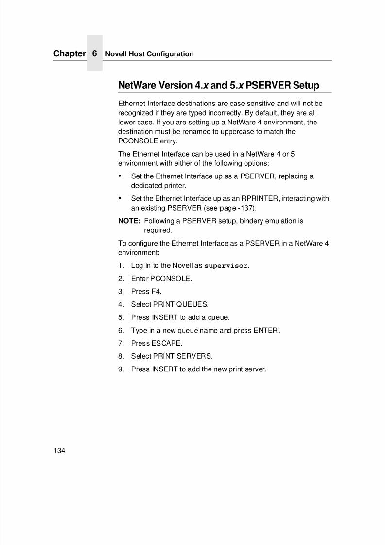
7/23/2019 54458302 IBM 6400
http://slidepdf.com/reader/full/54458302-ibm-6400 136/349
Chapter 6 Novell Host Configuration
134
NetWare Version 4.x and 5.x PSERVER Setup
Ethernet Interface destinations are case sensitive and will not berecognized if they are typed incorrectly. By default, they are alllower case. If you are setting up a NetWare 4 environment, thedestination must be renamed to uppercase to match thePCONSOLE entry.
The Ethernet Interface can be used in a NetWare 4 or 5environment with either of the following options:
• Set the Ethernet Interface up as a PSERVER, replacing adedicated printer.
• Set the Ethernet Interface up as an RPRINTER, interacting withan existing PSERVER (see page -137).
NOTE: Following a PSERVER setup, bindery emulation isrequired.
To configure the Ethernet Interface as a PSERVER in a NetWare 4environment:
1. Log in to the Novell as supervisor.
2. Enter PCONSOLE.
3. Press F4.
4. Select PRINT QUEUES.
5. Press INSERT to add a queue.
6. Type in a new queue name and press ENTER.
7. Press ESCAPE.
8. Select PRINT SERVERS.
9. Press INSERT to add the new print server.
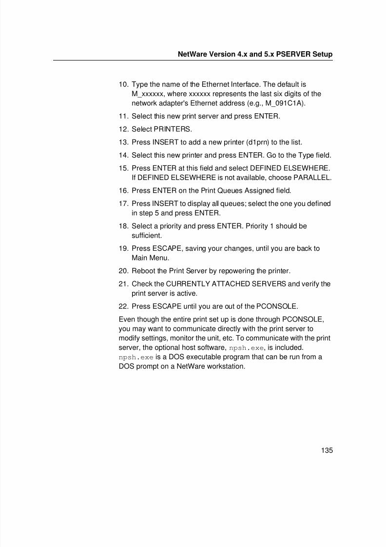
7/23/2019 54458302 IBM 6400
http://slidepdf.com/reader/full/54458302-ibm-6400 137/349
NetWare Version 4.x and 5.x PSERVER Setup
135
10. Type the name of the Ethernet Interface. The default is
M_xxxxxx, where xxxxxx represents the last six digits of thenetwork adapter's Ethernet address (e.g., M_091C1A).
11. Select this new print server and press ENTER.
12. Select PRINTERS.
13. Press INSERT to add a new printer (d1prn) to the list.
14. Select this new printer and press ENTER. Go to the Type field.
15. Press ENTER at this field and select DEFINED ELSEWHERE.If DEFINED ELSEWHERE is not available, choose PARALLEL.
16. Press ENTER on the Print Queues Assigned field.17. Press INSERT to display all queues; select the one you defined
in step 5 and press ENTER.
18. Select a priority and press ENTER. Priority 1 should besufficient.
19. Press ESCAPE, saving your changes, until you are back toMain Menu.
20. Reboot the Print Server by repowering the printer.
21. Check the CURRENTLY ATTACHED SERVERS and verify theprint server is active.
22. Press ESCAPE until you are out of the PCONSOLE.
Even though the entire print set up is done through PCONSOLE,you may want to communicate directly with the print server tomodify settings, monitor the unit, etc. To communicate with the printserver, the optional host software, npsh.exe, is included.npsh.exe is a DOS executable program that can be run from aDOS prompt on a NetWare workstation.
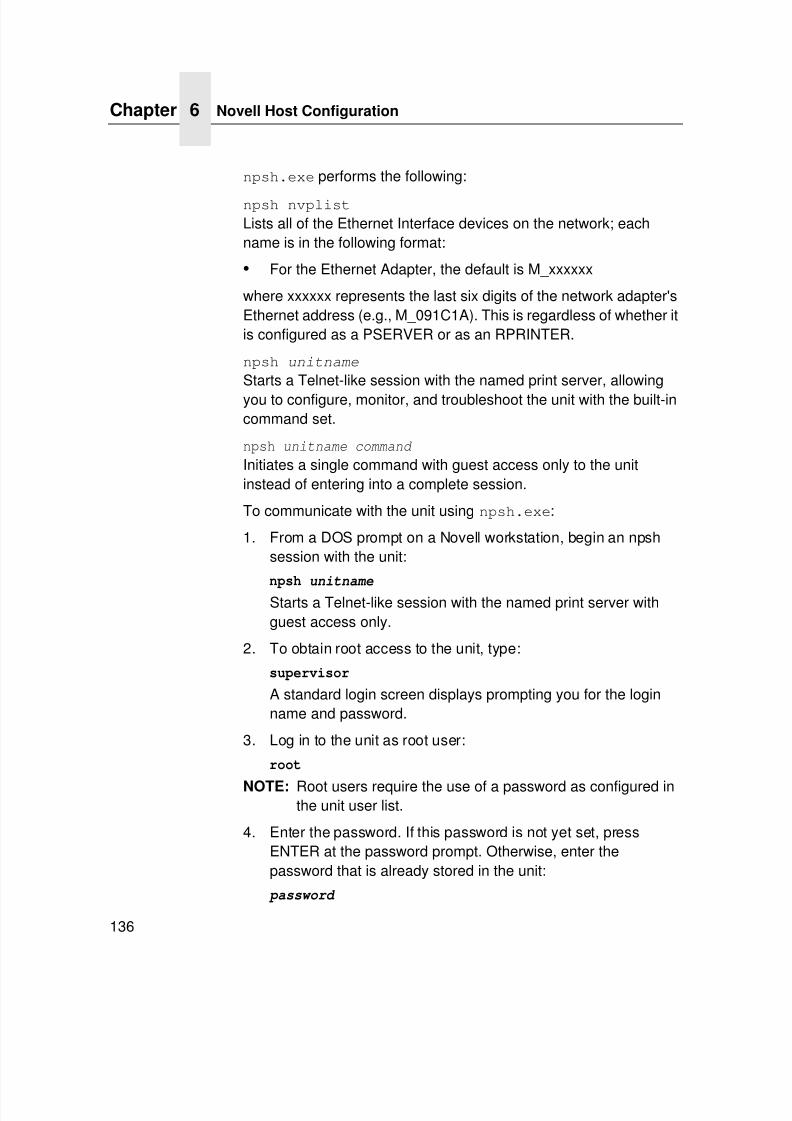
7/23/2019 54458302 IBM 6400
http://slidepdf.com/reader/full/54458302-ibm-6400 138/349
Chapter 6 Novell Host Configuration
136
npsh.exe performs the following:
npsh nvplist
Lists all of the Ethernet Interface devices on the network; eachname is in the following format:
• For the Ethernet Adapter, the default is M_xxxxxx
where xxxxxx represents the last six digits of the network adapter'sEthernet address (e.g., M_091C1A). This is regardless of whether itis configured as a PSERVER or as an RPRINTER.
npsh unitname
Starts a Telnet-like session with the named print server, allowingyou to configure, monitor, and troubleshoot the unit with the built-incommand set.
npsh unitname command
Initiates a single command with guest access only to the unitinstead of entering into a complete session.
To communicate with the unit using npsh.exe:
1. From a DOS prompt on a Novell workstation, begin an npshsession with the unit:
npsh unitnameStarts a Telnet-like session with the named print server withguest access only.
2. To obtain root access to the unit, type:
supervisor
A standard login screen displays prompting you for the loginname and password.
3. Log in to the unit as root user:
root
NOTE: Root users require the use of a password as configured inthe unit user list.
4. Enter the password. If this password is not yet set, pressENTER at the password prompt. Otherwise, enter thepassword that is already stored in the unit:
password
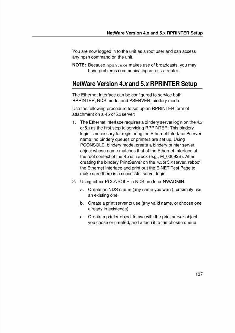
7/23/2019 54458302 IBM 6400
http://slidepdf.com/reader/full/54458302-ibm-6400 139/349
NetWare Version 4.x and 5.x RPRINTER Setup
137
You are now logged in to the unit as a root user and can access
any npsh command on the unit.NOTE: Because npsh.exe makes use of broadcasts, you may
have problems communicating across a router.
NetWare Version 4.x and 5.x RPRINTER Setup
The Ethernet Interface can be configured to service bothRPRINTER, NDS mode, and PSERVER, bindery mode.
Use the following procedure to set up an RPRINTER form of
attachment on a 4.x
or 5.x
server:1. The Ethernet Interface requires a bindery server login on the 4.x
or 5.x as the first step to servicing RPRINTER. This binderylogin is necessary for registering the Ethernet Interface Pservername; no bindery queues or printers are set up. UsingPCONSOLE, bindery mode, create a bindery printer serverobject whose name matches that of the Ethernet Interface atthe root context of the 4.x or 5.x box (e.g., M_03092B). Aftercreating the bindery PrintServer on the 4.x or 5.x server, rebootthe Ethernet Interface and print out the E-NET Test Page to
make sure there is a successful server login.2. Using either PCONSOLE in NDS mode or NWADMIN:
a. Create an NDS queue (any name you want), or simply usean existing one
b. Create a print server to use (any valid name, or choose onealready in existence)
c. Create a printer object to use with the print server objectyou chose or created, and attach it to the chosen queue
7/23/2019 54458302 IBM 6400
http://slidepdf.com/reader/full/54458302-ibm-6400 140/349
Chapter 6 Novell Host Configuration
138
NOTE: The 4.x or 5.x queue name, print server name, and printer
object do not have to match any Ethernet Interface name;multiple printers can be defined, but only one print servercan be attached to.
Example:
NDS queue name: FinanceNDS print server name: Fin_QNDS printer name: Fin_Prt_1NDS printer name: Accounting_Prt_1
3. At a 4.x or 5.x console session, if a pserver.nlm session is
already running for Fin_Q, first unload it, then reload it to findthe new objects, or simply issue load pserver Fin_Q.
If you are successful, the print server console screen will showa “printer status” option. In the “printer status” window, note thenumbers assigned to the printers you created. Assume for ourexample that one printer previously existed (number 0), and weare adding two more whose numbers became 1 and 2.
NOTE: On the load command, you must strictly follow the case ofthe name (this is not required on the Ethernet Interface).
4. Via a Telnet or npsh session, create RPRINTER attachments:store rprinter add Fin_Q 1 d1prn
This command assigns destination d1prn as the RPRINTER 1service path.
store rprinter add Fin_Q 2 d4prn
This command assigns destination d4prn as the RPRINTER 2service path.
For Ethernet Interface entries, case does not have to beobserved. Also, if you want to change the destination names
from dx prn, do so first with the set dest <dest> name <newname> command, being sure to use the save command sothese reappear after a reboot.
5. Reboot the Ethernet Interface adapter (power the printer offand on, or use the reset command) so the new RPRINTERservice names are broadcast.
7/23/2019 54458302 IBM 6400
http://slidepdf.com/reader/full/54458302-ibm-6400 141/349
NetWare Version 4.x and 5.x RPRINTER Setup
139
6. Open a Telnet or npsh session and log into the Ethernet
Interface. Wait a minute or two, then use the list rprinter command, and you should see your entries. You could also dothis by looking at the connection status on the 4.x or 5.x PSERVER printer status entries.
7. If you add, delete, or change RPRINTER entries on theEthernet Interface or 4.x or 5.x console, you should alwaysunload and reload the pserver.nlm module to register thechanges. The Ethernet Interface can be configured and readybefore the pserver.nlm is reloaded, or the Ethernet Interfacecan be reset after pserver.nlm is reloaded.
8. A Web browser can also be used to see the RPRINTERattachments and status.
Novell Troubleshooting Tips
This section provides information on possible solutions to somestandard configuration errors. If you require technical support,please have as much of the following information available whenyou call:
1. Level of software are you running.
2. Type of attachment do you have.
3. Your host operating system.
4. A detailed description of the problem.
5. When and how often the problem occurs.
6. A detailed description of your network and the componentsattached.
Please follow these tips to determine what the problem may be withyour Ethernet Interface configuration.
7/23/2019 54458302 IBM 6400
http://slidepdf.com/reader/full/54458302-ibm-6400 142/349
Chapter 6 Novell Troubleshooting Tips
140
NetWare 3.x - No PSERVER Connection
• Was the Ethernet Interface power cycled after the PCONSOLEsteps were completed? This will make the print server boot upand realize which print queue and file server it needs to service.
• Is the Ethernet Interface already servicing a queue on anotherfile server? If so, it cannot service another file server at thesame time.
• When defining a new print server within PCONSOLE, didyou use the correct name for the Ethernet Interface(e.g., M_091C1A)?
For the Ethernet Adapter, it recognizes itself as the default,M_xxxxxx, where xxxxxx represents the last six digits of thenetwork adapter's Ethernet address (e.g., M_091C1A) foundon the configuration printout.
• When defining a new printer name within PCONSOLE, didyou use a predefined destination/queue rather than a name ofyour own? By default, the Ethernet Interface only recognizesnames like d1prn. All other names will be ignored by thedevice.
• Is the Ethernet Interface in Bindery mode as seen under thelist pserver output on the device? If servicing only aNetWare 3.x file server, it must be set to handle Binderyservices. The default setting is Bindery.
• Is there an available NetWare user license for the EthernetInterface to use while it acts as a PSERVER? Every PSERVERtakes up one user license since it logs into the Novell fileserver.
• Have you given the connection process some time after
repowering the Ethernet Interface? In larger Novellenvironments, the file server identification and connectionprocess can take several minutes.

7/23/2019 54458302 IBM 6400
http://slidepdf.com/reader/full/54458302-ibm-6400 143/349

7/23/2019 54458302 IBM 6400
http://slidepdf.com/reader/full/54458302-ibm-6400 144/349
Chapter 6 Novell Troubleshooting Tips
142
7/23/2019 54458302 IBM 6400
http://slidepdf.com/reader/full/54458302-ibm-6400 145/349
143
7 Novell ConfigurationFor 10/100Base-T
Interfaces
Overview
ADAPTER,WIRELESS
This chapter applies to the Ethernet Adapter and Wireless Interfaceand provides additional information for Novell environments usingthe 10/100Base-T interface, including:
• Ethernet Interface Configuration. This section includessetting the preferred file server, setting password security,
adjusting polling time, changing the Ethernet Interface name,changing the Ethernet Interface frame type, changing theEthernet Interface mode, setting the Ethernet Interface NDScontext, and setting the Ethernet Interface preferred NDS tree.
• Host Configuration. This section includes NDS PSERVERsetup, Bindery PSERVER setup, referencing a Bindery queuein NDS, and RPRINTER/NPRINTER setups.
• Troubleshooting tips. This section covers PSERVER setups,RPRINTER/NPRINTER setups, and printing related problems.
7/23/2019 54458302 IBM 6400
http://slidepdf.com/reader/full/54458302-ibm-6400 146/349
Chapter 7 Novell Ethernet Interface Configuration (10/100Base-T)
144
Novell Ethernet Interface Configuration (10/100Base-T)
ADAPTER,WIRELESS
There are no mandatory Novell settings needed before the printserver can be detected on the network. However, there can besome mandatory settings needed before a Novell print queue canbe serviced by the Ethernet Interface. These mandatory settingsare covered separately for Netware 3.x , 4.x and 5.x under the HostConfiguration heading.
The print server setup in a Novell environment is much simpler thanthat required in a TCP/IP one. No addresses, masks, or router
entries are necessary and, in most cases, the Ethernet Interfacecan simply be connected to the network, turned on, and thenconfigured for printing from a Novell station through PCONSOLE orNetware Administrator.
However, there are some optional parameters you may wish tochange, such as the preferred file server(s), print server password,polling time, frame type, print server name, NDS context, and NDSpreferred tree. The following sections describe these optionalparameters.
Preferred File Server (NDS and Bindery Setups)
In a bindery setup, the preferred file server specifies the file serveron which the print server object was created. In an NDS setup, itspecifies a file server on which the print server object resides.Since NDS is distributed, most administrators will not know whichfile server(s) the print server object is actually stored on, so in mostNDS environments this option is not used. This feature is useful in alarge Novell network, so that the Ethernet Interface does not ignoreimportant file servers. If you are setting up the Ethernet Interface to
work with a Bindery file server, it is a good idea to set a preferredserver on the Ethernet Interface.
7/23/2019 54458302 IBM 6400
http://slidepdf.com/reader/full/54458302-ibm-6400 147/349
7/23/2019 54458302 IBM 6400
http://slidepdf.com/reader/full/54458302-ibm-6400 148/349
Chapter 7 Novell Ethernet Interface Configuration (10/100Base-T)
146
Removing Preferred File Server
HTML Method
1. Load a Web browser on a network station that cancommunicate with the print server over TCP/IP.
2. Direct your Web browser to URL:http://EthernetInterfaceIPaddress/
networkConf.html
(e.g., http://192.75.11.9/networkConf.html).
NOTE: If prompted for a “User ID” and password first, type in root
for the ID and press ENTER at the password prompt (sincethere is no password by default).
3. Look under the “Novell” section and remove the name of thepreferred file server from the “File Server” field.
4. Click the SUBMIT button when done and physically repowerthe print server to make the new settings take effect.
Manual (Telnet) Method
1. Telnet to the print server:
telnet ipaddress
NOTE: If prompted for a “User ID” and password first, type in root for the ID and press ENTER at the password prompt (sincethere is no password by default).
2. You should see a prompt with the Ethernet Interface IPaddress:ipaddress:root>
3. At the prompt, enter:store pserver novell fserver del fservername
where fservername is the name of the Novell file server youwant to remove as a preferred file server.
4. Reset the unit to ensure the changes take effect.reset

7/23/2019 54458302 IBM 6400
http://slidepdf.com/reader/full/54458302-ibm-6400 149/349
Setting Password Security (NDS and Bindery Setups)
147
Setting Password Security
(NDS and Bindery Setups)
Besides the general security measures, a Novell setup providesfurther password security. A password can be set on the EthernetInterface and within your PCONSOLE or Netware Administratorsetup so that when the Ethernet Interface tries to login to the fileserver, the passwords are compared.
To set the password on the Novell host for use in a PSERVERsetup, you will need to:
Netware 4.x and 5.x
1. Log in to Netware Administrator on your Novell host as a userwith security equal to “Admin.”
2. Double click the print server object you are using for yoursetup. This will bring up the print server objects details page.
3. Select the “Change Password...” button on the “Identification”page.
4. At the prompts, type and retype the new password. Click OK
when you are finished.5. Proceed to the next section to store the password on the
Ethernet Interface.
Netware 3.x
1. Log in to PCONSOLE on your Novell host as supervisor.
2. Select “Print Server Information” from the main menu.
3. Select the appropriate printer and press ENTER.
4. Select “Change Password.”5. At the prompts, type and retype the new password. Press
ENTER when you are finished.
6. Proceed to the next section to store the password on theEthernet Interface.
7/23/2019 54458302 IBM 6400
http://slidepdf.com/reader/full/54458302-ibm-6400 150/349
Chapter 7 Novell Ethernet Interface Configuration (10/100Base-T)
148
Print Server Setup - HTML Method
1. Load a Web browser on a network station that cancommunicate with the print server over TCP/IP.
2. Direct your Web browser to URL:http://EthernetInterfaceIPaddress/
networkConf.html
(e.g., http://192.75.11.9/networkConf.html).
NOTE: If prompted for a “User ID” and password first, type root forthe ID and press ENTER at the password prompt (sincethere is no password by default).
3. Look under the “Novell” section and add the new password tothe “Pserver Password” field.
NOTE: The passwords entered in Netware Administrator orPCONSOLE must match the password set on the unit.
4. Click the SUBMIT button when done and physically repowerthe printer to make the new settings take effect.
Print Server Setup - Manual (Telnet) Method
1. Telnet to the print server:telnet ipaddress
NOTE: If prompted for a “User ID” and password first, type root forthe ID and press ENTER at the password prompt sincethere is no password by default.
2. You should see a prompt with the Ethernet Interface IPaddress:ipaddress:root>
3. At the prompt, enter:store pserver novell passwd password
NOTE: The passwords entered in Netware Administrator orPCONSOLE must match the password set on the unit.
4. Reset the unit to ensure the changes take effect:reset
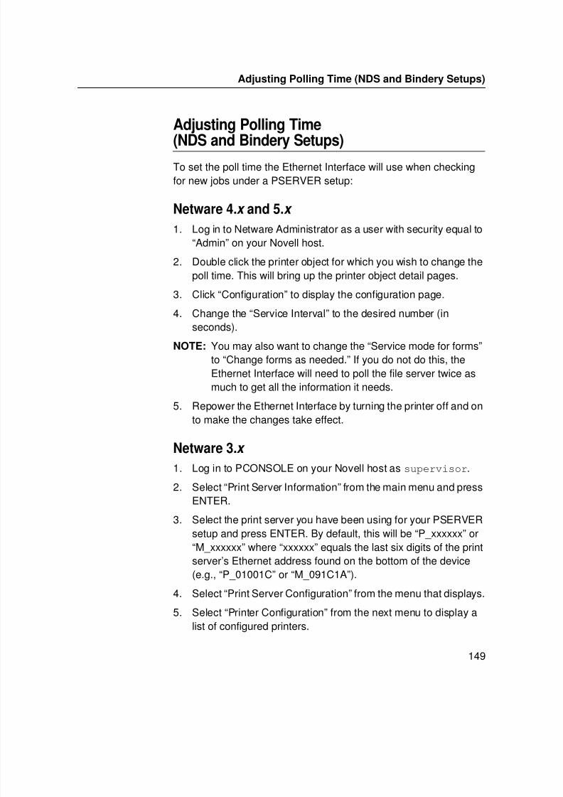
7/23/2019 54458302 IBM 6400
http://slidepdf.com/reader/full/54458302-ibm-6400 151/349
Adjusting Polling Time (NDS and Bindery Setups)
149
Adjusting Polling Time
(NDS and Bindery Setups)
To set the poll time the Ethernet Interface will use when checkingfor new jobs under a PSERVER setup:
Netware 4.x and 5.x
1. Log in to Netware Administrator as a user with security equal to“Admin” on your Novell host.
2. Double click the printer object for which you wish to change the
poll time. This will bring up the printer object detail pages.3. Click “Configuration” to display the configuration page.
4. Change the “Service Interval” to the desired number (inseconds).
NOTE: You may also want to change the “Service mode for forms”to “Change forms as needed.” If you do not do this, theEthernet Interface will need to poll the file server twice asmuch to get all the information it needs.
5. Repower the Ethernet Interface by turning the printer off and on
to make the changes take effect.
Netware 3.x
1. Log in to PCONSOLE on your Novell host as supervisor.
2. Select “Print Server Information” from the main menu and pressENTER.
3. Select the print server you have been using for your PSERVERsetup and press ENTER. By default, this will be “P_xxxxxx” or“M_xxxxxx” where “xxxxxx” equals the last six digits of the printserver’s Ethernet address found on the bottom of the device(e.g., “P_01001C” or “M_091C1A”).
4. Select “Print Server Configuration” from the menu that displays.
5. Select “Printer Configuration” from the next menu to display alist of configured printers.
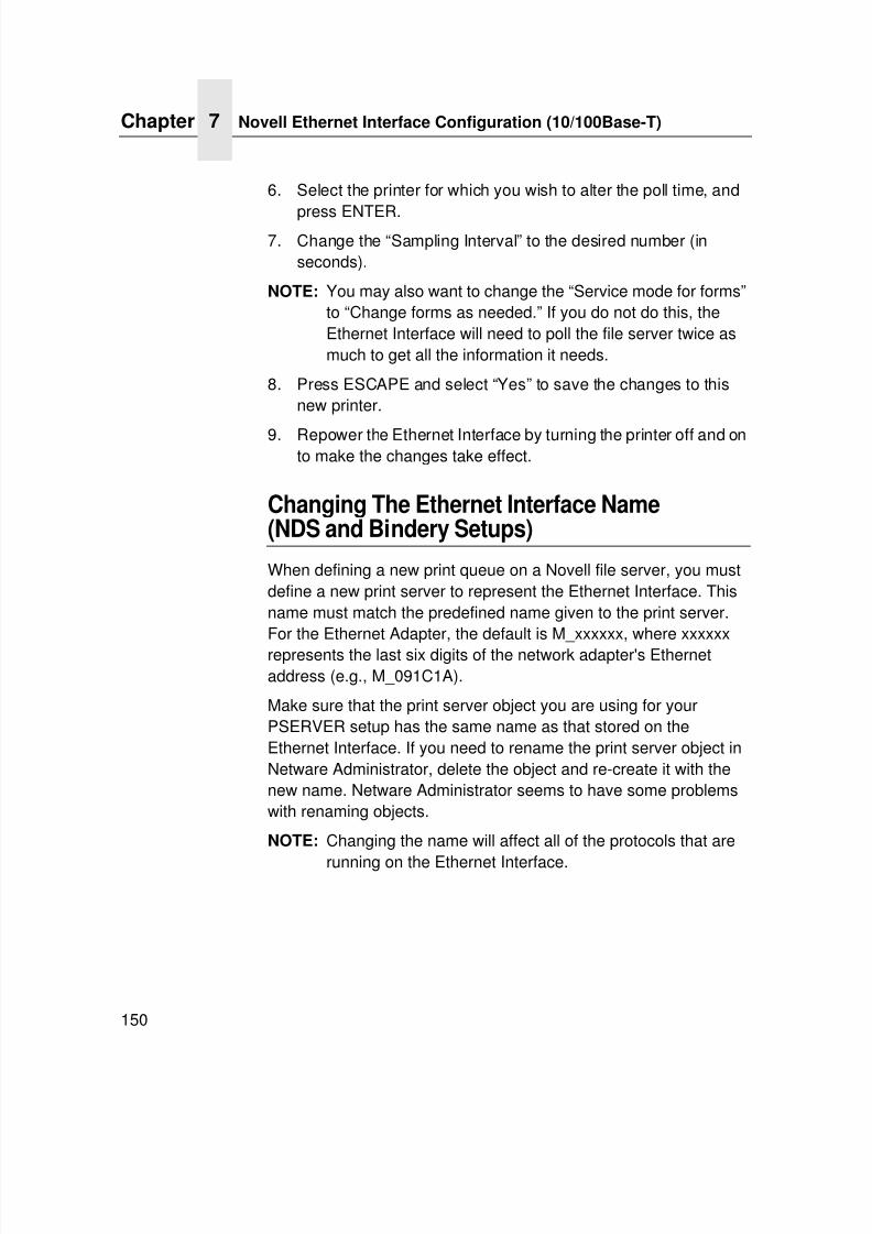
7/23/2019 54458302 IBM 6400
http://slidepdf.com/reader/full/54458302-ibm-6400 152/349
Chapter 7 Novell Ethernet Interface Configuration (10/100Base-T)
150
6. Select the printer for which you wish to alter the poll time, and
press ENTER.7. Change the “Sampling Interval” to the desired number (in
seconds).
NOTE: You may also want to change the “Service mode for forms”to “Change forms as needed.” If you do not do this, theEthernet Interface will need to poll the file server twice asmuch to get all the information it needs.
8. Press ESCAPE and select “Yes” to save the changes to thisnew printer.
9. Repower the Ethernet Interface by turning the printer off and onto make the changes take effect.
Changing The Ethernet Interface Name(NDS and Bindery Setups)
When defining a new print queue on a Novell file server, you mustdefine a new print server to represent the Ethernet Interface. Thisname must match the predefined name given to the print server.For the Ethernet Adapter, the default is M_xxxxxx, where xxxxxxrepresents the last six digits of the network adapter's Ethernetaddress (e.g., M_091C1A).
Make sure that the print server object you are using for yourPSERVER setup has the same name as that stored on theEthernet Interface. If you need to rename the print server object inNetware Administrator, delete the object and re-create it with thenew name. Netware Administrator seems to have some problemswith renaming objects.
NOTE: Changing the name will affect all of the protocols that are
running on the Ethernet Interface.
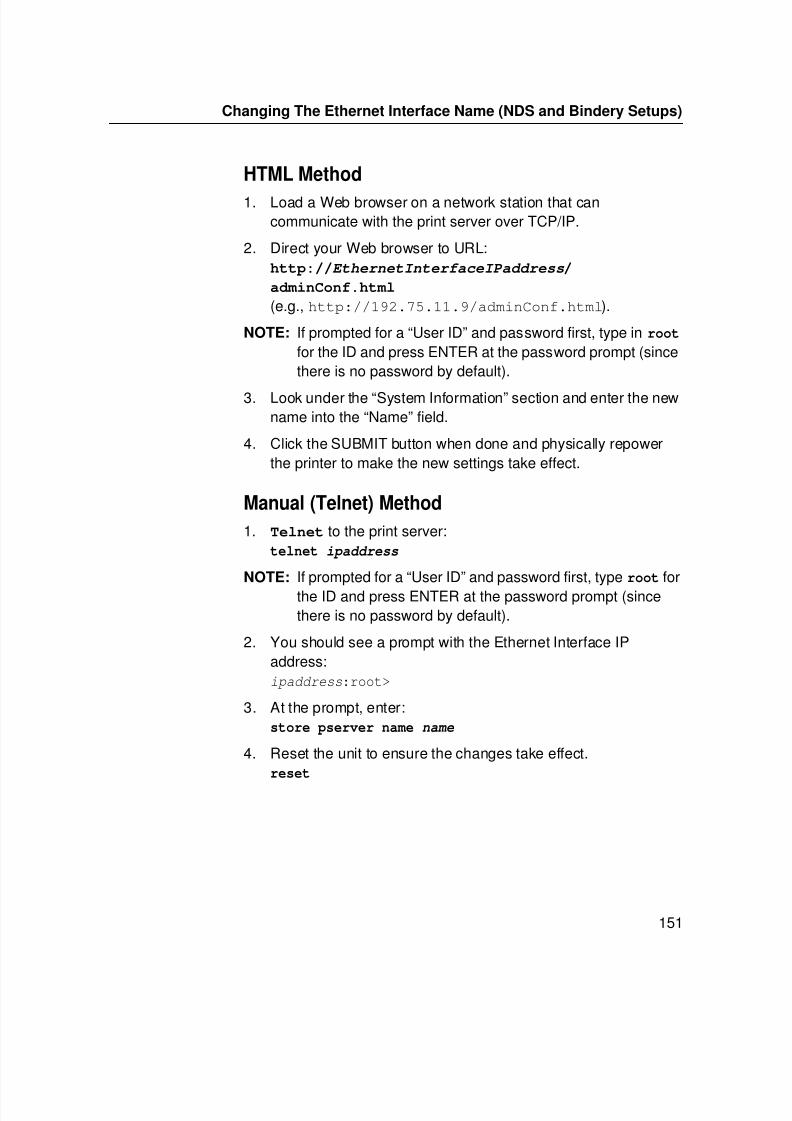
7/23/2019 54458302 IBM 6400
http://slidepdf.com/reader/full/54458302-ibm-6400 153/349
Changing The Ethernet Interface Name (NDS and Bindery Setups)
151
HTML Method
1. Load a Web browser on a network station that cancommunicate with the print server over TCP/IP.
2. Direct your Web browser to URL:http://EthernetInterfaceIPaddress/
adminConf.html
(e.g., http://192.75.11.9/adminConf.html).
NOTE: If prompted for a “User ID” and password first, type in root for the ID and press ENTER at the password prompt (sincethere is no password by default).
3. Look under the “System Information” section and enter the newname into the “Name” field.
4. Click the SUBMIT button when done and physically repowerthe printer to make the new settings take effect.
Manual (Telnet) Method
1. Telnet to the print server:telnet ipaddress
NOTE: If prompted for a “User ID” and password first, type root forthe ID and press ENTER at the password prompt (sincethere is no password by default).
2. You should see a prompt with the Ethernet Interface IPaddress:ipaddress:root>
3. At the prompt, enter:store pserver name name
4. Reset the unit to ensure the changes take effect.reset
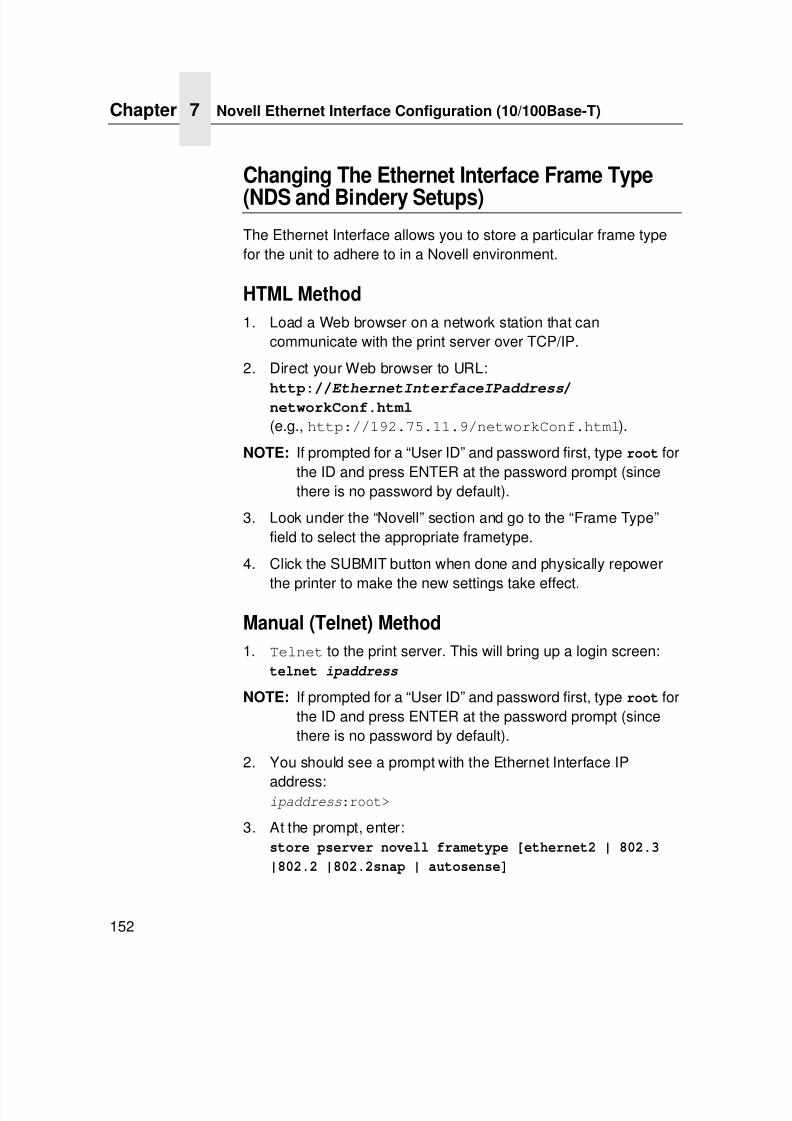
7/23/2019 54458302 IBM 6400
http://slidepdf.com/reader/full/54458302-ibm-6400 154/349
Chapter 7 Novell Ethernet Interface Configuration (10/100Base-T)
152
Changing The Ethernet Interface Frame Type
(NDS and Bindery Setups)
The Ethernet Interface allows you to store a particular frame typefor the unit to adhere to in a Novell environment.
HTML Method
1. Load a Web browser on a network station that cancommunicate with the print server over TCP/IP.
2. Direct your Web browser to URL:
http://EthernetInterfaceIPaddress/networkConf.html
(e.g., http://192.75.11.9/networkConf.html).
NOTE: If prompted for a “User ID” and password first, type root forthe ID and press ENTER at the password prompt (sincethere is no password by default).
3. Look under the “Novell” section and go to the “Frame Type”field to select the appropriate frametype.
4. Click the SUBMIT button when done and physically repower
the printer to make the new settings take effect.
Manual (Telnet) Method
1. Telnet to the print server. This will bring up a login screen:telnet ipaddress
NOTE: If prompted for a “User ID” and password first, type root forthe ID and press ENTER at the password prompt (sincethere is no password by default).
2. You should see a prompt with the Ethernet Interface IP
address:ipaddress:root>
3. At the prompt, enter:store pserver novell frametype [ethernet2 | 802.3
|802.2 |802.2snap | autosense]
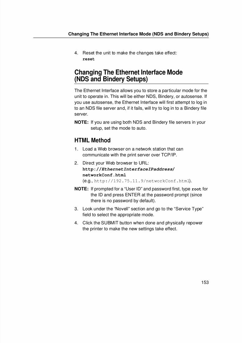
7/23/2019 54458302 IBM 6400
http://slidepdf.com/reader/full/54458302-ibm-6400 155/349
Changing The Ethernet Interface Mode (NDS and Bindery Setups)
153
4. Reset the unit to make the changes take effect:
reset
Changing The Ethernet Interface Mode(NDS and Bindery Setups)
The Ethernet Interface allows you to store a particular mode for theunit to operate in. This will be either NDS, Bindery, or autosense. Ifyou use autosense, the Ethernet Interface will first attempt to log into an NDS file server and, if it fails, will try to log in to a Bindery fileserver.
NOTE: If you are using both NDS and Bindery file servers in yoursetup, set the mode to auto.
HTML Method
1. Load a Web browser on a network station that cancommunicate with the print server over TCP/IP.
2. Direct your Web browser to URL:http://EthernetInterfaceIPaddress/
networkConf.html
(e.g., http://192.75.11.9/networkConf.html).
NOTE: If prompted for a “User ID” and password first, type root forthe ID and press ENTER at the password prompt (sincethere is no password by default).
3. Look under the “Novell” section and go to the “Service Type”field to select the appropriate mode.
4. Click the SUBMIT button when done and physically repowerthe printer to make the new settings take effect.
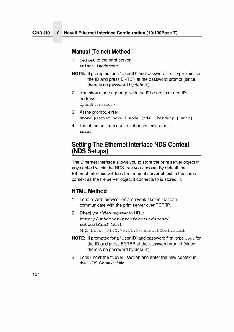
7/23/2019 54458302 IBM 6400
http://slidepdf.com/reader/full/54458302-ibm-6400 156/349
Chapter 7 Novell Ethernet Interface Configuration (10/100Base-T)
154
Manual (Telnet) Method
1. Telnet to the print server:telnet ipaddress
NOTE: If prompted for a “User ID” and password first, type root forthe ID and press ENTER at the password prompt (sincethere is no password by default).
2. You should see a prompt with the Ethernet Interface IPaddress:ipaddress:root>
3. At the prompt, enter:store pserver novell mode [nds | bindery | auto]
4. Reset the unit to make the changes take effect:reset
Setting The Ethernet Interface NDS Context(NDS Setups)
The Ethernet Interface allows you to store the print server object inany context within the NDS tree you choose. By default the
Ethernet Interface will look for the print server object in the samecontext as the file server object it connects to is stored in.
HTML Method
1. Load a Web browser on a network station that cancommunicate with the print server over TCP/IP.
2. Direct your Web browser to URL:http://EthernetInterfaceIPaddress/
networkConf.html
(e.g., http://192.75.11.9/networkConf.html).NOTE: If prompted for a “User ID” and password first, type root for
the ID and press ENTER at the password prompt (sincethere is no password by default).
3. Look under the “Novell” section and enter the new context inthe “NDS Context” field.
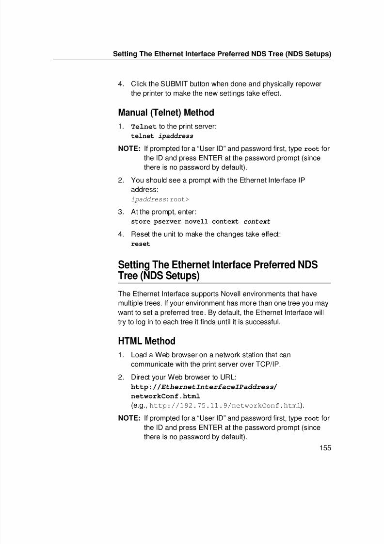
7/23/2019 54458302 IBM 6400
http://slidepdf.com/reader/full/54458302-ibm-6400 157/349
Setting The Ethernet Interface Preferred NDS Tree (NDS Setups)
155
4. Click the SUBMIT button when done and physically repower
the printer to make the new settings take effect.
Manual (Telnet) Method
1. Telnet to the print server:telnet ipaddress
NOTE: If prompted for a “User ID” and password first, type root forthe ID and press ENTER at the password prompt (sincethere is no password by default).
2. You should see a prompt with the Ethernet Interface IP
address:ipaddress:root>
3. At the prompt, enter:store pserver novell context context
4. Reset the unit to make the changes take effect:reset
Setting The Ethernet Interface Preferred NDSTree (NDS Setups)
The Ethernet Interface supports Novell environments that havemultiple trees. If your environment has more than one tree you maywant to set a preferred tree. By default, the Ethernet Interface willtry to log in to each tree it finds until it is successful.
HTML Method
1. Load a Web browser on a network station that cancommunicate with the print server over TCP/IP.
2. Direct your Web browser to URL:http://EthernetInterfaceIPaddress/
networkConf.html
(e.g., http://192.75.11.9/networkConf.html).
NOTE: If prompted for a “User ID” and password first, type root forthe ID and press ENTER at the password prompt (sincethere is no password by default).
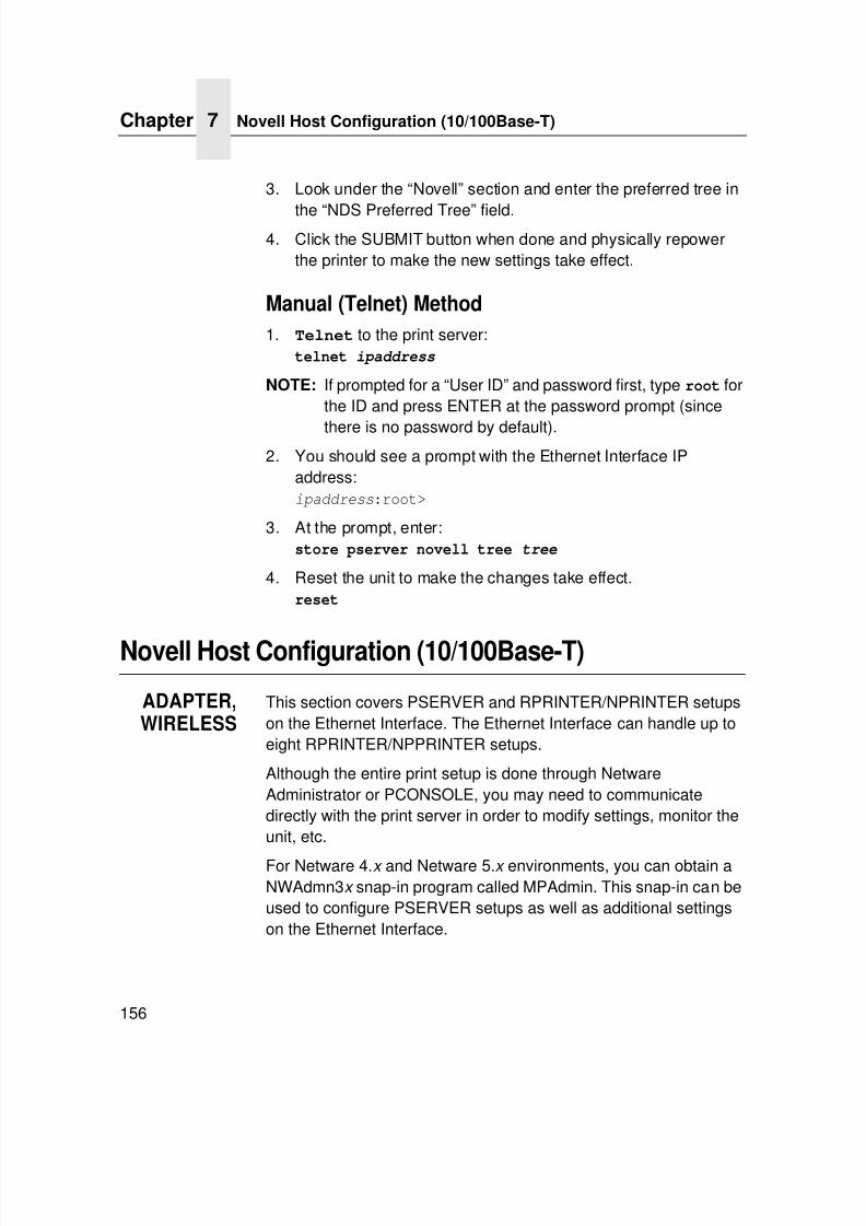
7/23/2019 54458302 IBM 6400
http://slidepdf.com/reader/full/54458302-ibm-6400 158/349
Chapter 7 Novell Host Configuration (10/100Base-T)
156
3. Look under the “Novell” section and enter the preferred tree in
the “NDS Preferred Tree” field.4. Click the SUBMIT button when done and physically repower
the printer to make the new settings take effect.
Manual (Telnet) Method
1. Telnet to the print server:telnet ipaddress
NOTE: If prompted for a “User ID” and password first, type root forthe ID and press ENTER at the password prompt (since
there is no password by default).2. You should see a prompt with the Ethernet Interface IP
address:ipaddress:root>
3. At the prompt, enter:store pserver novell tree tree
4. Reset the unit to make the changes take effect.reset
Novell Host Configuration (10/100Base-T)
ADAPTER,WIRELESS
This section covers PSERVER and RPRINTER/NPRINTER setupson the Ethernet Interface. The Ethernet Interface can handle up toeight RPRINTER/NPPRINTER setups.
Although the entire print setup is done through NetwareAdministrator or PCONSOLE, you may need to communicatedirectly with the print server in order to modify settings, monitor theunit, etc.
For Netware 4.x and Netware 5.x environments, you can obtain aNWAdmn3x snap-in program called MPAdmin. This snap-in can beused to configure PSERVER setups as well as additional settingson the Ethernet Interface.
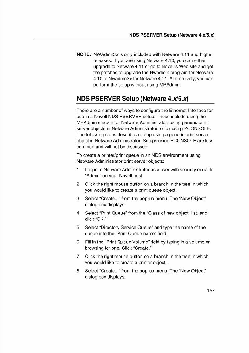
7/23/2019 54458302 IBM 6400
http://slidepdf.com/reader/full/54458302-ibm-6400 159/349
NDS PSERVER Setup (Netware 4.x/5.x)
157
NOTE: NWAdmn3x is only included with Netware 4.11 and higher
releases. If you are using Netware 4.10, you can eitherupgrade to Netware 4.11 or go to Novell’s Web site and getthe patches to upgrade the Nwadmin program for Netware4.10 to Nwadmn3x for Netware 4.11. Alternatively, you canperform the setup without using MPAdmin.
NDS PSERVER Setup (Netware 4.x /5.x )
There are a number of ways to configure the Ethernet Interface foruse in a Novell NDS PSERVER setup. These include using the
MPAdmin snap-in for Netware Administrator, using generic printserver objects in Netware Administrator, or by using PCONSOLE.The following steps describe a setup using a generic print serverobject in Netware Administrator. Setups using PCONSOLE are lesscommon and will not be discussed.
To create a printer/print queue in an NDS environment usingNetware Administrator print server objects:
1. Log in to Netware Administrator as a user with security equal to“Admin” on your Novell host.
2. Click the right mouse button on a branch in the tree in whichyou would like to create a print queue object.
3. Select “Create...” from the pop-up menu. The “New Object”dialog box displays.
4. Select “Print Queue” from the “Class of new object” list, andclick “OK.”
5. Select “Directory Service Queue” and type the name of thequeue into the “Print Queue name” field.
6. Fill in the “Print Queue Volume” field by typing in a volume or
browsing for one. Click “Create.”
7. Click the right mouse button on a branch in the tree in whichyou would like to create a printer object.
8. Select “Create...” from the pop-up menu. The “New Object”dialog box displays.
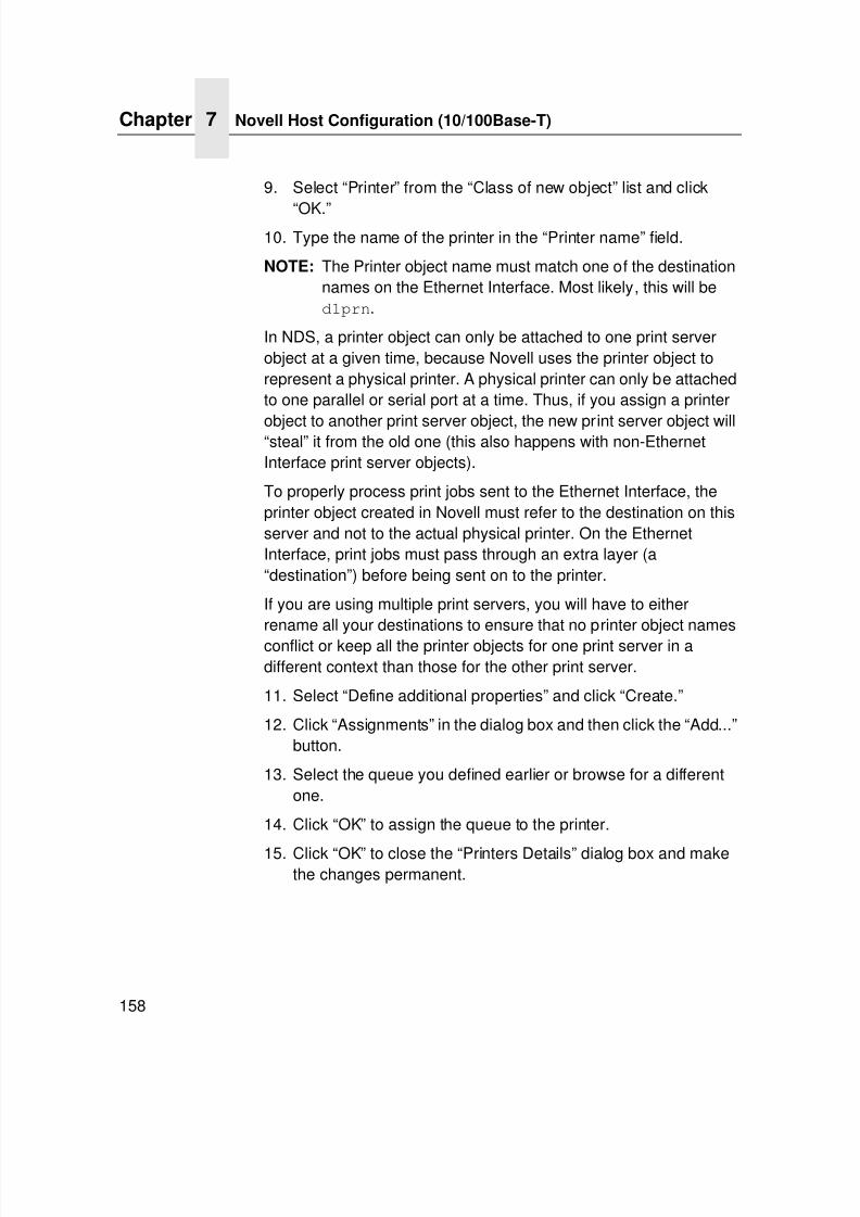
7/23/2019 54458302 IBM 6400
http://slidepdf.com/reader/full/54458302-ibm-6400 160/349
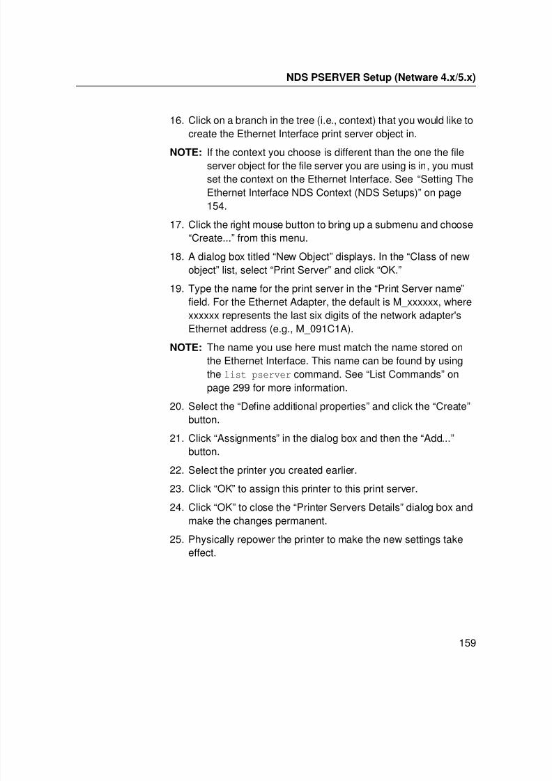
7/23/2019 54458302 IBM 6400
http://slidepdf.com/reader/full/54458302-ibm-6400 161/349
NDS PSERVER Setup (Netware 4.x/5.x)
159
16. Click on a branch in the tree (i.e., context) that you would like to
create the Ethernet Interface print server object in.NOTE: If the context you choose is different than the one the file
server object for the file server you are using is in, you mustset the context on the Ethernet Interface. See “Setting TheEthernet Interface NDS Context (NDS Setups)” on page154.
17. Click the right mouse button to bring up a submenu and choose“Create...” from this menu.
18. A dialog box titled “New Object” displays. In the “Class of new
object” list, select “Print Server” and click “OK.”19. Type the name for the print server in the “Print Server name”
field. For the Ethernet Adapter, the default is M_xxxxxx, wherexxxxxx represents the last six digits of the network adapter'sEthernet address (e.g., M_091C1A).
NOTE: The name you use here must match the name stored onthe Ethernet Interface. This name can be found by usingthe list pserver command. See “List Commands” onpage 299 for more information.
20. Select the “Define additional properties” and click the “Create”button.
21. Click “Assignments” in the dialog box and then the “Add...”button.
22. Select the printer you created earlier.
23. Click “OK” to assign this printer to this print server.
24. Click “OK” to close the “Printer Servers Details” dialog box andmake the changes permanent.
25. Physically repower the printer to make the new settings takeeffect.
7/23/2019 54458302 IBM 6400
http://slidepdf.com/reader/full/54458302-ibm-6400 162/349
Chapter 7 Novell Host Configuration (10/100Base-T)
160
Bindery PSERVER Setup
(Netware 3.x , Netware 4.x , and Netware 5.x )
A Bindery PSERVER setup is possible under both Netware 3.x ,Netware 4.x and Netware 5.x . If you are using Netware 4.x orNetware 5.x, Bindery emulation is required. Please consult yourNovell manual on how to set up Bindery emulation. A Bindery setup using PCONSOLE in Netware 3.x is described in “NetWareVersion 3.x RPRINTER Setup” on page -131. The setup usingPCONSOLE in Netware 4.x or Netware 5.x is described in“NetWare Version 4.x and 5.x RPRINTER Setup” on page -137.
Referencing A Bindery Queue In NDS(Netware 3.x , Netware 4.x , and Netware 5.x )
If you would like to reference a Bindery queue when you performyour PSERVER setup in NDS, you must create a PSERVER objectfor the Ethernet Interface on the file server where the Binderyqueue resides. This is important because, in order to service thequeue, the Ethernet Interface must log in to the queue’s file server.Since the queue is not an NDS queue, the Ethernet Interface
cannot log in under NDS, so it must log in under Bindery.This will only work if there is a valid PSERVER object on the fileserver. This PSERVER object must have the same name that wasused for the NDS setup. For the Ethernet Adapter, the default isM_xxxxxx where xxxxxx represents the last six digits of the networkadapter's Ethernet address (e.g., M_091C1A). This PSERVERobject does not need any printers or queues assigned to it. Also,when referencing a Bindery queue in NDS, set the Novell Mode onthe Ethernet Interface to “auto” so that both NDS and Binderylogins are possible. See “Setting The Ethernet Interface NDSContext (NDS Setups)” on page 154.
7/23/2019 54458302 IBM 6400
http://slidepdf.com/reader/full/54458302-ibm-6400 163/349
RPRINTER/NPRINTER Setup (Netware 3.x, Netware 4.x, and Netware 5.x)
161
RPRINTER/NPRINTER Setup
(Netware 3.x , Netware 4.x , and Netware 5.x )
This procedure associates an existing PSERVER with a remoteEthernet Interface acting as a RPRINTER/NPRINTER in a Netware3.x , Netware 4.x , or Netware 5.x environment. It is the PSERVER’sresponsibility to get jobs from the queue and to pass them off to theEthernet Interface acting as the remote printer. Unlike a PSERVERsetup, the Ethernet Interface does not deal directly with the queues.
NOTE: As a RPRINTER/NPRINTER, the print server does not usea login ID. A non-Ethernet Interface print server such as
PSERVER.NLM or PSERVER.EXE must be running forRPRINTER to operate. Also, if the Ethernet Interface losesa connection to a PSERVER, it will automatically reconnectwhen that server becomes available again.
The following steps assume that you have created a PSERVERobject in Netware 3.x , Netware 4.x , or Netware 5.x and haveassigned printers and queues to it. If you have not already donethis, do it now. The setup is similar to creating a PSERVER setupfor the Ethernet Interface, except that there are no restrictionsabout which names may be used for the print server and printerobjects.
NOTE: Write down the printer number(s) assigned to the printer(s)you are going to be using for this setup. You will need themin a later step.
HTML Method
1. Load a PSERVER on your Netware 3.x , Netware 4.x , orNetware 5.x file server (i.e., issue a load pserver
pservername command on the file server).
NOTE: If it is an NDS PSERVER on a Netware 4.x /5.x file server,you must specify the PSERVER name and context forpservername. For example:load pserver .sales_ps.sales.microplex
2. Load a Web browser on a network station that cancommunicate with the print server over TCP/IP.
7/23/2019 54458302 IBM 6400
http://slidepdf.com/reader/full/54458302-ibm-6400 164/349
Chapter 7 Novell Host Configuration (10/100Base-T)
162
3. Direct your Web browser to URL:
http://EthernetInterfaceIPaddress/networkConf.html
(e.g., http://192.75.11.9/networkConf.html).
NOTE: If prompted for a “User ID” and password first, type in root for the ID and press ENTER at the password prompt (sincethere is no password by default).
4. Look under the “Novell” section and find a row in theRPRINTER category.
5. Click “Enabled” and enter the name used with the
PSERVER.NLM into the “Print Server Name” field.NOTE: If it is an NDS pserver, enter only the PSERVER name and
not the context (e.g., sales_ps).
6. Enter the printer number of the printer you would like servicedinto the “Printer Number” field, and then select the destinationon the Ethernet Interface you would like to use for output.
7. Repeat steps 4 through 6 for each additional printer you wouldlike to have serviced.
8. Click the SUBMIT button when done and physically repower
the printer to make the new settings take effect.
Manual (Telnet) Method
1. Load a PSERVER on your Netware 3.x , Netware 4.x , orNetware 5.x file server (i.e., issue a load pserver
pservername command on the file server).
NOTE: If it is an NDS PSERVER on a Netware 4.x /5.x file server,you must specify the pserver name and context for pservername. For example:
load pserver .sales_ps.sales.IBM
2. Telnet to the print server:telnet ipaddress
NOTE: If prompted for a “User ID” and password first, type root forthe ID and press ENTER at the password prompt (sincethere is no password by default).
7/23/2019 54458302 IBM 6400
http://slidepdf.com/reader/full/54458302-ibm-6400 165/349
7/23/2019 54458302 IBM 6400
http://slidepdf.com/reader/full/54458302-ibm-6400 166/349
Chapter 7 Novell Host Configuration (10/100Base-T)
164
NDPS Configuration (Netware 4.11 and Above)
Overview
In 1998, Novell released a new printing system designed to makenetwork administration of printers easier and more fully functional.This system is called Novell Distributed Print Services (NDPS), andcan be used with Novell Netware 4.11 and above along with thesupporting software on clients. This section gives high-levelinstructions to install and use NDPS with the printer. Theseinstructions assume that you understand NDPS architecture wellenough to be able to use these instructions along with Novell'sinstructions to install the Ethernet Interface into NDPS. SeeNovell’s documentation to understand terms not defined here.
The drivers used with the IBM printer, can be found onwww.printers.ibm.com. For a driver to be automatically downloadedto a Windows machine when an NDPS printer is installed, the drivermust be installed into the NDPS Broker Resource ManagementService. See Novell’s documentation for more information.
The Ethernet Interface can be installed into NDPS using the NovellPrinter Gateway feature of NDPS. Within this Novell Printer
Gateway, various printer connection modes can be used to installthe printer into NDPS. The ones described here are:
• Setup using Forward Jobs to a Queue Mode
• Setup using LPR Mode
• Setup using RPRINTER Mode
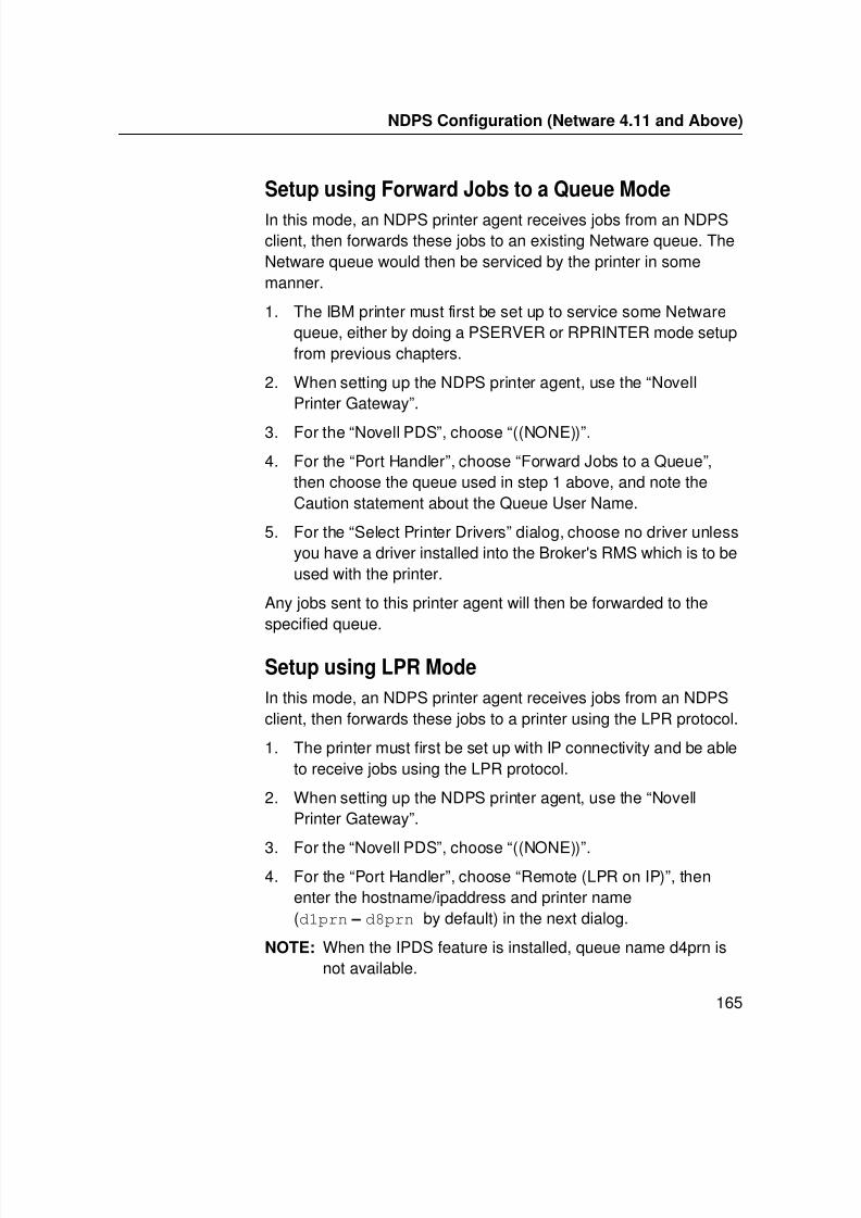
7/23/2019 54458302 IBM 6400
http://slidepdf.com/reader/full/54458302-ibm-6400 167/349
NDPS Configuration (Netware 4.11 and Above)
165
Setup using Forward Jobs to a Queue Mode
In this mode, an NDPS printer agent receives jobs from an NDPSclient, then forwards these jobs to an existing Netware queue. TheNetware queue would then be serviced by the printer in somemanner.
1. The IBM printer must first be set up to service some Netwarequeue, either by doing a PSERVER or RPRINTER mode setupfrom previous chapters.
2. When setting up the NDPS printer agent, use the “NovellPrinter Gateway”.
3. For the “Novell PDS”, choose “((NONE))”.
4. For the “Port Handler”, choose “Forward Jobs to a Queue”,then choose the queue used in step 1 above, and note theCaution statement about the Queue User Name.
5. For the “Select Printer Drivers” dialog, choose no driver unlessyou have a driver installed into the Broker's RMS which is to beused with the printer.
Any jobs sent to this printer agent will then be forwarded to thespecified queue.
Setup using LPR Mode
In this mode, an NDPS printer agent receives jobs from an NDPSclient, then forwards these jobs to a printer using the LPR protocol.
1. The printer must first be set up with IP connectivity and be ableto receive jobs using the LPR protocol.
2. When setting up the NDPS printer agent, use the “NovellPrinter Gateway”.
3. For the “Novell PDS”, choose “((NONE))”.4. For the “Port Handler”, choose “Remote (LPR on IP)”, then
enter the hostname/ipaddress and printer name(d1prn – d8prn by default) in the next dialog.
NOTE: When the IPDS feature is installed, queue name d4prn isnot available.
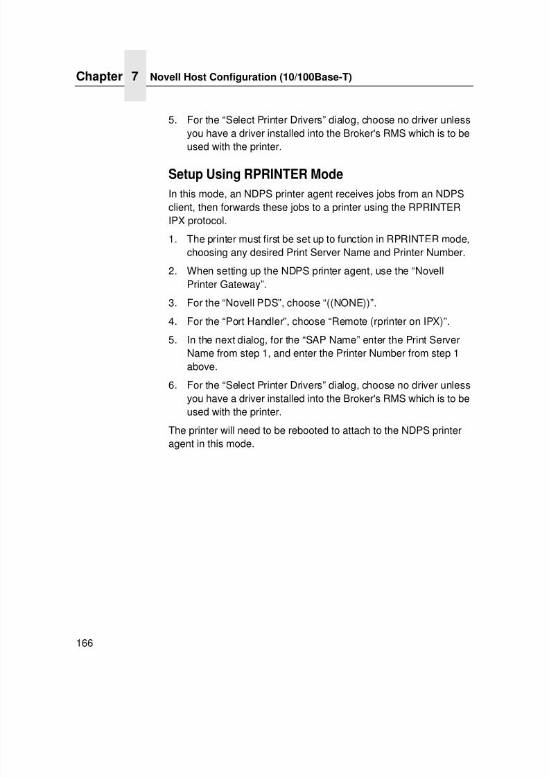
7/23/2019 54458302 IBM 6400
http://slidepdf.com/reader/full/54458302-ibm-6400 168/349
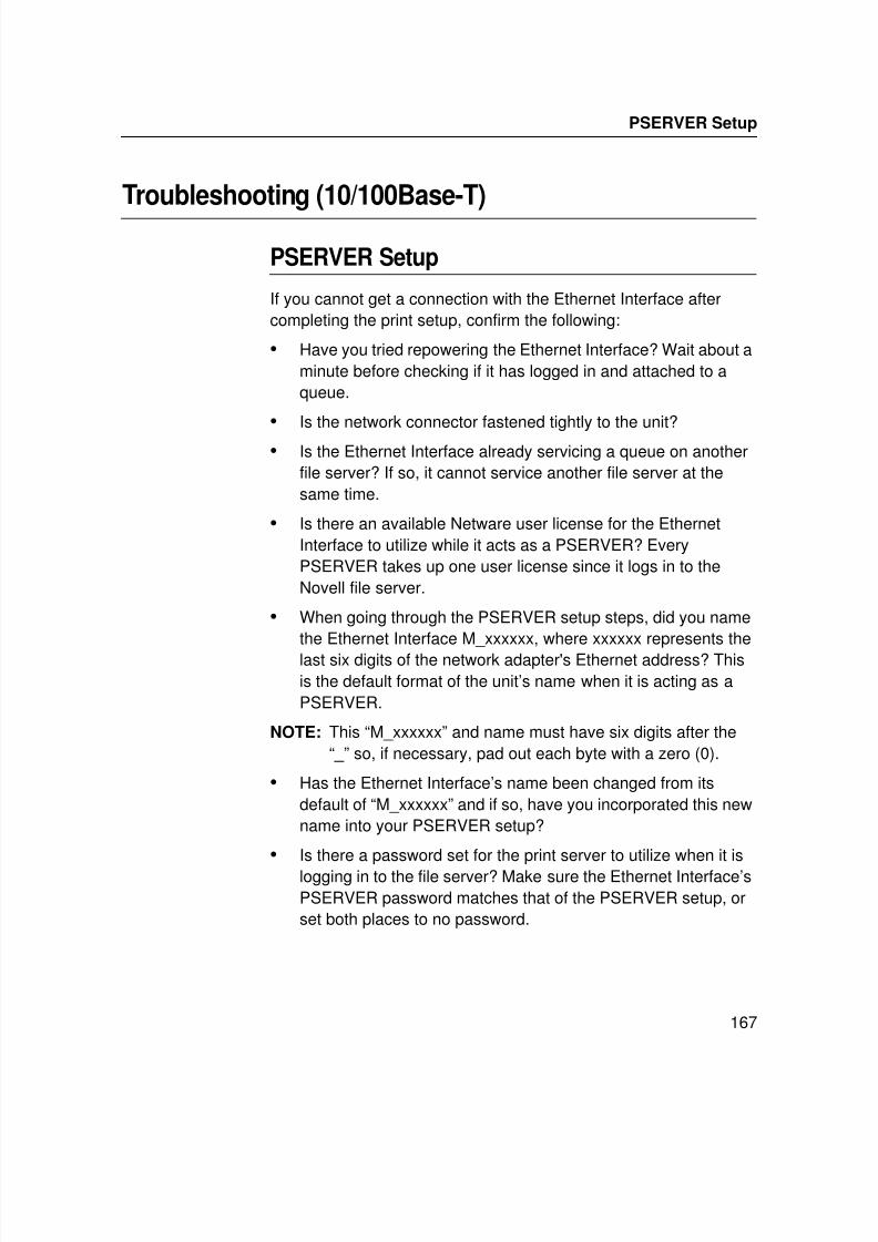
7/23/2019 54458302 IBM 6400
http://slidepdf.com/reader/full/54458302-ibm-6400 169/349
PSERVER Setup
167
Troubleshooting (10/100Base-T)
PSERVER Setup
If you cannot get a connection with the Ethernet Interface aftercompleting the print setup, confirm the following:
• Have you tried repowering the Ethernet Interface? Wait about aminute before checking if it has logged in and attached to aqueue.
• Is the network connector fastened tightly to the unit?
• Is the Ethernet Interface already servicing a queue on anotherfile server? If so, it cannot service another file server at thesame time.
• Is there an available Netware user license for the EthernetInterface to utilize while it acts as a PSERVER? EveryPSERVER takes up one user license since it logs in to theNovell file server.
• When going through the PSERVER setup steps, did you namethe Ethernet Interface M_xxxxxx, where xxxxxx represents thelast six digits of the network adapter's Ethernet address? Thisis the default format of the unit’s name when it is acting as aPSERVER.
NOTE: This “M_xxxxxx” and name must have six digits after the“ _ ” so, if necessary, pad out each byte with a zero (0).
• Has the Ethernet Interface’s name been changed from itsdefault of “M_xxxxxx” and if so, have you incorporated this newname into your PSERVER setup?
• Is there a password set for the print server to utilize when it islogging in to the file server? Make sure the Ethernet Interface’sPSERVER password matches that of the PSERVER setup, orset both places to no password.
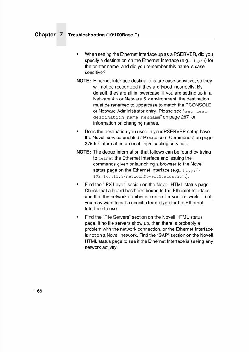
7/23/2019 54458302 IBM 6400
http://slidepdf.com/reader/full/54458302-ibm-6400 170/349
Chapter 7 Troubleshooting (10/100Base-T)
168
• When setting the Ethernet Interface up as a PSERVER, did you
specify a destination on the Ethernet Interface (e.g., d1prn) forthe printer name, and did you remember this name is casesensitive?
NOTE: Ethernet Interface destinations are case sensitive, so theywill not be recognized if they are typed incorrectly. Bydefault, they are all in lowercase. If you are setting up in aNetware 4.x or Netware 5.x environment, the destinationmust be renamed to uppercase to match the PCONSOLEor Netware Administrator entry. Please see “set destdestination name newname” on page 287 for
information on changing names.• Does the destination you used in your PSERVER setup have
the Novell service enabled? Please see “Commands” on page275 for information on enabling/disabling services.
NOTE: The debug information that follows can be found by tryingto telnet the Ethernet Interface and issuing thecommands given or launching a browser to the Novellstatus page on the Ethernet Interface (e.g., http://192.168.11.9/networkNovellStatus.html).
• Find the “IPX Layer” secion on the Novell HTML status page.Check that a board has been bound to the Ethernet Interfaceand that the network number is correct for your network. If not,you may want to set a specific frame type for the EthernetInterface to use.
• Find the “File Servers” section on the Novell HTML statuspage. If no file servers show up, then there is probably aproblem with the network connection, or the Ethernet Interfaceis not on a Novell network. Find the “SAP” section on the NovellHTML status page to see if the Ethernet Interface is seeing any
network activity.
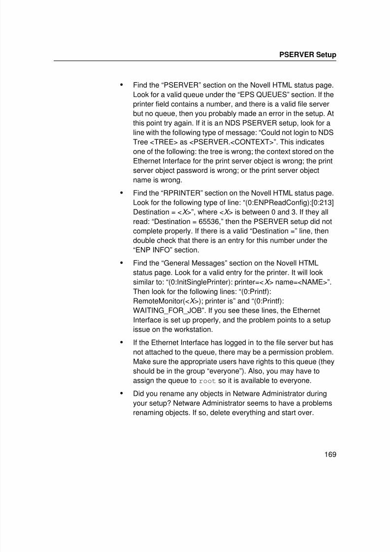
7/23/2019 54458302 IBM 6400
http://slidepdf.com/reader/full/54458302-ibm-6400 171/349
PSERVER Setup
169
• Find the “PSERVER” section on the Novell HTML status page.
Look for a valid queue under the “EPS QUEUES” section. If theprinter field contains a number, and there is a valid file serverbut no queue, then you probably made an error in the setup. Atthis point try again. If it is an NDS PSERVER setup, look for aline with the following type of message: “Could not login to NDSTree <TREE> as <PSERVER.<CONTEXT>”. This indicatesone of the following: the tree is wrong; the context stored on theEthernet Interface for the print server object is wrong; the printserver object password is wrong; or the print server objectname is wrong.
• Find the “RPRINTER” section on the Novell HTML status page.Look for the following type of line: “(0:ENPReadConfig):[0:213]Destination = <X >”, where <X > is between 0 and 3. If they allread: “Destination = 65536,” then the PSERVER setup did notcomplete properly. If there is a valid “Destination =” line, thendouble check that there is an entry for this number under the“ENP INFO” section.
• Find the “General Messages” section on the Novell HTMLstatus page. Look for a valid entry for the printer. It will looksimilar to: “(0:InitSinglePrinter): printer=<X > name=<NAME>”.
Then look for the following lines: “(0:Printf):RemoteMonitor(<X >); printer is” and “(0:Printf):WAITING_FOR_JOB”. If you see these lines, the EthernetInterface is set up properly, and the problem points to a setupissue on the workstation.
• If the Ethernet Interface has logged in to the file server but hasnot attached to the queue, there may be a permission problem.Make sure the appropriate users have rights to this queue (theyshould be in the group “everyone”). Also, you may have toassign the queue to root so it is available to everyone.
• Did you rename any objects in Netware Administrator duringyour setup? Netware Administrator seems to have a problemsrenaming objects. If so, delete everything and start over.
7/23/2019 54458302 IBM 6400
http://slidepdf.com/reader/full/54458302-ibm-6400 172/349
Chapter 7 Troubleshooting (10/100Base-T)
170
If none of these solutions help your situation, try the whole setup
again. Completely delete the setup that is giving you trouble and gothrough the setup again, following each step carefully.
NOTE: After completing a PSERVER setup and before beginninga new setup, be sure to reboot the printer. Wait at least aminute for the Print Server to login and attach to a queue.
RPRINTER/NPRINTER Setup
If you cannot get a connection with the Ethernet Interface aftercompleting the print setup, confirm the following:
• Have you tried repowering the printer? Wait about a minutebefore checking to see if it has logged in and attached to aqueue.
• Is the network connector fastened tightly to the unit?
• Is the Ethernet Interface already servicing a queue on anotherfile server? If so, it cannot service another file server at thesame time.
• Is an entry produced when a list rprinter telnet command
is done on the Ethernet Interface (not found on the NovellHTML status page)? When the Ethernet Interface is configuredas an RPRINTER, this command should produce theappropriate entry.
• If the Ethernet Interface has logged in to the file server but hasnot attached to the queue, there may be a permission problem.Make sure the appropriate users have rights to this queue (theyshould be in the group “everyone”). Also, you may have toassign the queue to root so it is available to everyone.
7/23/2019 54458302 IBM 6400
http://slidepdf.com/reader/full/54458302-ibm-6400 173/349
RPRINTER/NPRINTER Setup
171
• Does the destination you used in your RPRINTER setup have
the Novell service enabled? Please see “Commands” on page275 for information on enabling/disabling services.
• Find the “IPX Layer” section on the Novell HTML status page.Check that a board has been bound to the Ethernet Interfaceand that the network number is correct for your network. If not,set a specific frame type for the Ethernet Interface to use. Youcan find out what frame type is bound to which board numberfrom the “ODI Layer” section on the Novell HTML status page.
• Find the “SAP” section on the Novell HTML status page to seeif the Ethernet Interface is seeing any network activity.
• Find the “RPRINTER” section on the Novell HTML status page.Look for an entry for one of the numbers 4 to 7 under “ENPINFO.” The “dest” field should match the destination used onthe Ethernet Interface. If no entry is found, check that thedestination has the Novell service enabled. If the “ERROR-CODE” field has an error of 308, make sure no otherRPRINTER setup is servicing this printer object at the sametime. Only one RPRINTER connection is allowed to service aPSERVER.NLM printer.
• If the Ethernet Interface has logged in to the file server but hasnot attached to the queue, there may be a permission problem.Make sure the appropriate users have rights to this queue (theyshould be in the group “everyone”). Also, you may have toassign the queue to root so it is available to everyone.
If none of these help your situation, try the whole setup again.Completely delete the setup that is giving you trouble and gothrough the setup again following each step carefully.
NOTE: After completing a PSERVER set up and before beginning
a new set up, be sure to reboot the printer. Wait at least aminute for the Print Server to login and attach to a queue.
7/23/2019 54458302 IBM 6400
http://slidepdf.com/reader/full/54458302-ibm-6400 174/349
Chapter 7 Troubleshooting (10/100Base-T)
172
Printing Related
The Job Goes To The Queue But Nothing Prints
If nothing is printing, first make sure you have a connection to theEthernet Interface. Please see “RPRINTER/NPRINTER Setup” onpage 170 if you are having connection-related problems.Otherwise, consider these points when trying to solve printingproblems in a Novell environment:
• Does the job leave the queue or is it stuck there indefinitely? Ifit leaves properly, the problem points to the actual printing
mechanism on your Novell system (e.g., CAPTURE, NPRINT,etc.), to the print job format, or to the printer itself. Otherwise,review the configuration steps you have already followed.
• Have you confirmed that you can print from the EthernetInterface to the printer and ignore the Novell setup altogether?Please see “start fox|tts|loopb prn” on page -304 for agood test.
• Is anything happening on the printer when the print job is sent?Sometimes, the print job may have arrived at the printer butmight be waiting for a manual form feed. If so see “Commands”on page 275 for information on trailer strings.
• Is the printing mechanism you are using (e.g., CAPTURE,NPRINT, etc.) configured to service the appropriate queue?
• Is the Ethernet Interface configured as the queue’s “CurrentlyAttached Server”? If not, make sure you have associated thequeue and the printer. See “Novell Host Configuration” on page128.
• Is there a hold on the print job? If you select the job fromPCONSOLE’s CURRENT PRINT JOB ENTRIES, change theUser Hold or Operator Hold to “no.”
• If you look in PCONSOLE’s CURRENT QUEUE STATUSwithin the PRINT QUEUE INFORMATION menu, is the serverconfigured to service entries in this queue? It is possible to turnservicing off here.
7/23/2019 54458302 IBM 6400
http://slidepdf.com/reader/full/54458302-ibm-6400 175/349
Printing Related
173
If you have followed the suggestions above and are still having
printing problems, try rebooting the Ethernet Interface. Then eitherreview every step you took when configuring the Ethernet Interfaceor try redoing the setup, paying special attention to each stepexplained in “Novell Host Configuration” on page 128.
The Job Prints Incorrectly
This category can be broken down into several sub-categories suchas lost characters, garbled data, extra banner pages, or blankpages at the end of a job. However, the reason for these mishapscan generally be traced back to the printing mechanism used on
your Novell system. Consider these points when configuring yourprint method (e.g., CAPTURE, NPRINT, etc.):
• Did you include the “No Tabs” option?
• Did you specify “No Banner” with PostScript printers?
• Did you turn off banner pages and form feeds if this is alreadytaken care of within an application or on the Ethernet Interface?Doubling up these types of print features is easy to do sincethese options are provided both on the Ethernet Interface (in amodel) and within the print command.
• Are you running the latest version of PSERVER (later than1.22)? If not, upgrade the PSERVER software.
• In a PSERVER setup, did you ensure that the printer name(e.g., d1prn) was set up as “Defined Elsewhere”?
• Is the timeout option in the CAPTURE command set highenough so the printer does not time out before the printprocessing has had a chance to complete? This can be aproblem with graphic jobs.
• When garbled data persists, consider the following:• tab expansion (xtab) set on (in a model) with graphic jobs
• the correct driver for the printer if printing from withinWindows
For additional information on these suggestions, please refer toyour Netware user manuals.

7/23/2019 54458302 IBM 6400
http://slidepdf.com/reader/full/54458302-ibm-6400 176/349
Chapter 7 Troubleshooting (10/100Base-T)
174
7/23/2019 54458302 IBM 6400
http://slidepdf.com/reader/full/54458302-ibm-6400 177/349
175
8 iSeries Configuration, ASCII Printer
OverviewThis chapter details a complete iSeries configuration setupincluding:
• Developing Line Descriptions with CRTLINETH
• Configuring the iSeries for TCP/IP
• Configuring the iSeries for Printing
• Verifying Printing from the iSeries
This document assumes no iSeries printer configuration has beendone. If any configuration has been done, please follow theprocedure to the point at which continued configuration is required.
Developing Line Descriptions With CRTLINETH
For each LAN adapter on the iSeries, a line description needs to becreated for the Ethernet Interface.
If a line description already exists, make sure the SSAP listincludes default options “AA” and “12.” You must also know theLAN speed for the iSeries LAN adapter.
NOTE: To change a line description, you need to vary the line offbefore making the change. After making the change, youneed to vary the line back on.
To change an existing line description, use the CHGLINETHcommand. To create a line description, use CRTLINETH.
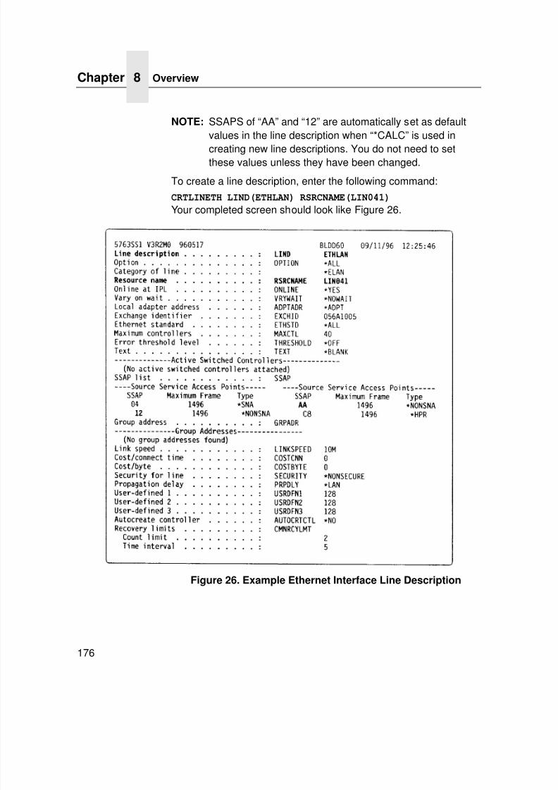
7/23/2019 54458302 IBM 6400
http://slidepdf.com/reader/full/54458302-ibm-6400 178/349
Chapter 8 Overview
176
NOTE: SSAPS of “AA” and “12” are automatically set as default
values in the line description when “*CALC” is used increating new line descriptions. You do not need to setthese values unless they have been changed.
To create a line description, enter the following command:
CRTLINETH LIND(ETHLAN) RSRCNAME(LIN041)
Your completed screen should look like Figure 26.
Figure 26. Example Ethernet Interface Line Description
7/23/2019 54458302 IBM 6400
http://slidepdf.com/reader/full/54458302-ibm-6400 179/349
Configuring With ADDTCPIFC
177
The following three parameters must be specified:
Line Description (LIND)
The line description name is the user's name for the iSeriesadapter. This name must be identical to the name entered when theTCP/IP is configured on the iSeries.
Resource Name (RSRCNAME)
The system-assigned name for the interface (for example, LIN041).
SSAPWhen *CALC is used, the values of “12” and “AA” are enteredautomatically as defaults. Verify that those SSAP values have notbeen changed.
Configuring iSeries For ASCII Using TCP/IP
The next step is to configure the interface on the iSeries forTCP/IP.
NOTE: The iSeries interface is not the Ethernet Interface. Do notset the iSeries interface address to the same address asthe Ethernet Interface IP address. Also, do not add theEthernet Interface to the iSeries TCP/IP interface list.
Configuring With ADDTCPIFC
ADDTCPIFC is used to add a TCP/IP interface to the iSeries. Thisstep configures the iSeries for attachments to a TCP/IP network.
At the iSeries command line, enter the following command: ADDTCPIFC INTNETADR ('9.99.15.188') LIND(ETHLAN)SUBNETMASK('255.255.255.0')
Your completed screen should look like Figure 27.
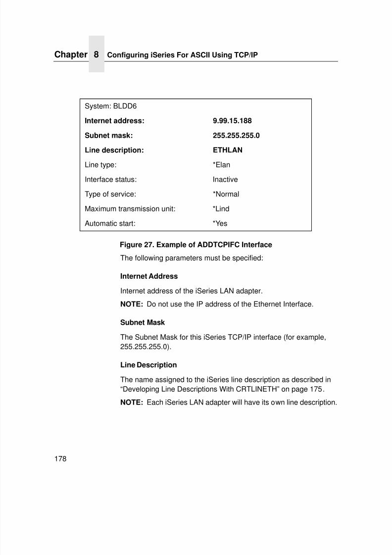
7/23/2019 54458302 IBM 6400
http://slidepdf.com/reader/full/54458302-ibm-6400 180/349
Chapter 8 Configuring iSeries For ASCII Using TCP/IP
178
Figure 27. Example of ADDTCPIFC Interface
The following parameters must be specified:
Internet Address
Internet address of the iSeries LAN adapter.NOTE: Do not use the IP address of the Ethernet Interface.
Subnet Mask
The Subnet Mask for this iSeries TCP/IP interface (for example,255.255.255.0).
Line Description
The name assigned to the iSeries line description as described in
“Developing Line Descriptions With CRTLINETH” on page 175.
NOTE: Each iSeries LAN adapter will have its own line description.
System: BLDD6
Internet address: 9.99.15.188
Subnet mask: 255.255.255.0
Line description: ETHLAN
Line type: *Elan
Interface status: Inactive
Type of service: *Normal
Maximum transmission unit: *Lind
Automatic start: *Yes
7/23/2019 54458302 IBM 6400
http://slidepdf.com/reader/full/54458302-ibm-6400 181/349
Configuring A Router Definition With ADDTCPRTE
179
Configuring A Router Definition With
ADDTCPRTE
If necessary, use the ADDTCPRTE command to create a routedefinition. This is required if the printer is somewhere other than ona local segment and must cross bridges.
Configuring A Local Domain And Hostname
The iSeries print commands, described in “Setting Up Printing ForASCII Files” on page 180, require a local name and hostname. If
you have already configured LAN attached TCP/IP printers on theiSeries system, you will have a local domain name and hostnameconfigured on the system.
NOTE: If you already have a local domain name and hostnameconfigured on the system, do not change your setup.
If the local domain name and hostname file is empty, the file mustbe set up. This control file information is used to determine if a printrequest comes from an authorized host.
To configure the local domain and hostname, you will run the
CFGTCP command and select Option “12” from the menu. Enter alocal domain name, such as city.company.com. Enter a localhostname, such as as400-01. This is the name of your iSeriessystem and must match the hostname for your system in the hostentry table. Refer to “Configuring A TCP/IP Host Table Entry” formore information.
NOTE: If the printer and iSeries are not on the same local LANsegment, use CFGTCP Option 2 to verify that there is aroute defined in the TCP/IP route list.
Configuring A TCP/IP Host Table Entry
Although creating a TCP/IP host table entry is optional, it is a goodidea to take this step. Add the iSeries name and the IP address ofthe LAN adapter to the “Host Table Entries.”
7/23/2019 54458302 IBM 6400
http://slidepdf.com/reader/full/54458302-ibm-6400 182/349
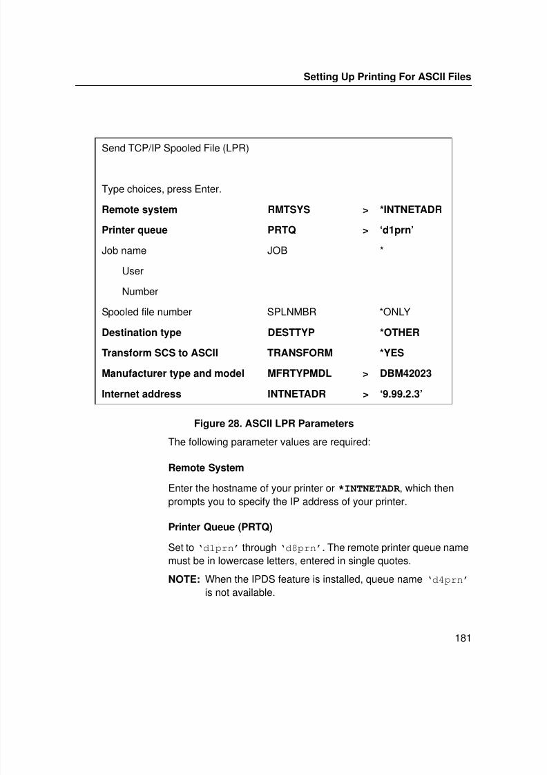
7/23/2019 54458302 IBM 6400
http://slidepdf.com/reader/full/54458302-ibm-6400 183/349
Setting Up Printing For ASCII Files
181
Figure 28. ASCII LPR Parameters
The following parameter values are required:
Remote System
Enter the hostname of your printer or *INTNETADR , which thenprompts you to specify the IP address of your printer.
Printer Queue (PRTQ)
Set to ‘d1prn’ through ‘d8prn’. The remote printer queue namemust be in lowercase letters, entered in single quotes.
NOTE: When the IPDS feature is installed, queue name ‘d4prn’ is not available.
Send TCP/IP Spooled File (LPR)
Type choices, press Enter.
Remote system RMTSYS > *INTNETADR
Printer queue PRTQ > ‘d1prn’
Job name JOB *
User
Number
Spooled file number SPLNMBR *ONLY
Destination type DESTTYP *OTHER
Transform SCS to ASCII TRANSFORM *YES
Manufacturer type and model MFRTYPMDL > DBM42023
Internet address INTNETADR > ‘9.99.2.3’
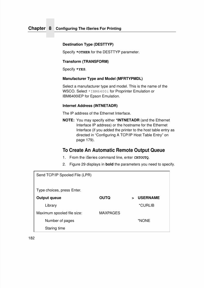
7/23/2019 54458302 IBM 6400
http://slidepdf.com/reader/full/54458302-ibm-6400 184/349
Chapter 8 Configuring The iSeries For Printing
182
Destination Type (DESTTYP)
Specify *OTHER for the DESTTYP parameter.
Transform (TRANSFORM)
Specify *YES.
Manufacturer Type and Model (MFRTYPMDL)
Select a manufacturer type and model. This is the name of theWSCO. Select *IBM6400i for Proprinter Emulation orIBM6400iEP for Epson Emulation.
Internet Address (INTNETADR)
The IP address of the Ethernet Interface.
NOTE: You may specify either *INTNETADR (and the EthernetInterface IP address) or the hostname for the EthernetInterface (if you added the printer to the host table entry asdirected in “Configuring A TCP/IP Host Table Entry” onpage 179).
To Create An Automatic Remote Output Queue1. From the iSeries command line, enter CRTOUTQ.
2. Figure 29 displays in bold the parameters you need to specify.
Send TCP/IP Spooled File (LPR)
Type choices, press Enter.
Output queue OUTQ > USERNAME
Library *CURLIB
Maximum spooled file size: MAXPAGES
Number of pages *NONE
Staring time
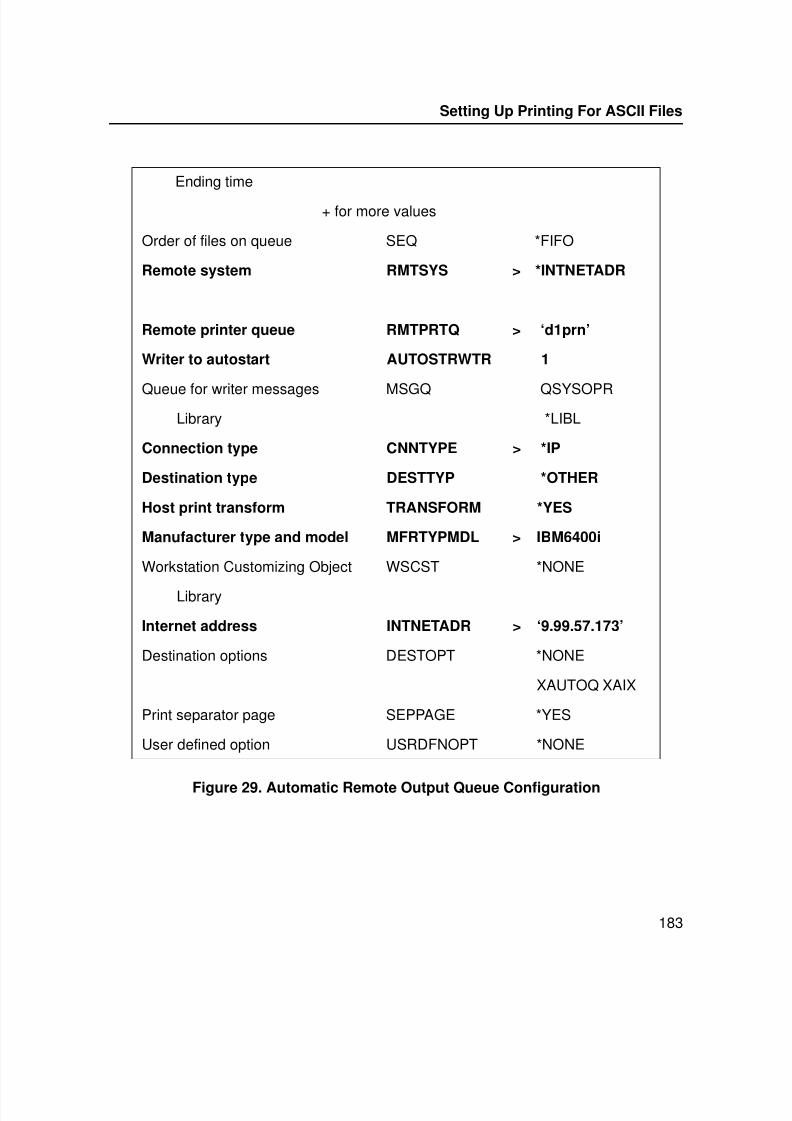
7/23/2019 54458302 IBM 6400
http://slidepdf.com/reader/full/54458302-ibm-6400 185/349
Setting Up Printing For ASCII Files
183
Figure 29. Automatic Remote Output Queue Configuration
Ending time
+ for more values
Order of files on queue SEQ *FIFO
Remote system RMTSYS > *INTNETADR
Remote printer queue RMTPRTQ > ‘d1prn’
Writer to autostart AUTOSTRWTR 1
Queue for writer messages MSGQ QSYSOPRLibrary *LIBL
Connection type CNNTYPE > *IP
Destination type DESTTYP *OTHER
Host print transform TRANSFORM *YES
Manufacturer type and model MFRTYPMDL > IBM6400i
Workstation Customizing Object WSCST *NONE
Library
Internet address INTNETADR > ‘9.99.57.173’
Destination options DESTOPT *NONE
XAUTOQ XAIX
Print separator page SEPPAGE *YES
User defined option USRDFNOPT *NONE
7/23/2019 54458302 IBM 6400
http://slidepdf.com/reader/full/54458302-ibm-6400 186/349
Chapter 8 Configuring The iSeries For Printing
184
3. Enter values for the following parameters:
Output Queue (OUTQ)
The name of the iSeries output queue. The name can beanything you would like. This name is not the same as theprinter internal queue name, ‘d1prn’.
Remote System (RMTSYS)
Internet address of the Ethernet Interface on the printer(*INTNETADR prompts you for this) or the hostname of the
Ethernet Interface.Remote Printer Queue (RMTPRTQ)
Default name of the network printer. Set for any of ‘d1prn’ through ‘d8prn’. The remote printer queue name must belowercase, entered in single quotes.
NOTE:When the IPDS feature is installed, queue name‘d4prn’ is not available.
Writer to Autostart (AUTOSRTWTR)
Set the value to 1. This will start the Remote Writer when thequeue is created, and it automatically starts the Remote Writerafter each IPL of the iSeries and whenever STRTCP is started.
Connection Type (CNNTYPE)
Specify this value as *IP.
Destination Type (DESTTYP)
Specify *OTHER . *OTHER is a performance enhancement, inwhich data is not required to be transformed again if theconnection is interrupted and allows printing of multiple copies.
Transform (TRANSFORM)
Specify this value as *YES.
7/23/2019 54458302 IBM 6400
http://slidepdf.com/reader/full/54458302-ibm-6400 187/349
Setting Up Printing For ASCII Files
185
Destination Options (DESTOPT)
Specify XAUTOQ, XAIX. XAUTOQ is a performanceenhancement, in which data is not required to be transformedagain if the connection is interrupted. XAIX allows printing ofmultiple copies.
Manufacturer Type (MFRTYPMDL)
Select a manufacturer type and model. This is the name of theWSCO. Select *IBM6400i for Proprinter Emulation. Or6400iEP for Proprinter for Epson Emulation.
Internet address (INTNETADR)
Specify the IP address of the printer.
Verify Printing On iSeries
This section verifies that the printer is capable of printing ASCII filesand that the printer can be pinged on the network.
To test ASCII printing:
1. Start TCP/IP, if it is not already running, by entering thecommand STRTCP.
2. Verify that the iSeries TCP/IP interface is active.
3. Ping the printer from an iSeries workstation with thecommand:
ping ip_address.
Where ip_address is the Internet address of the remotesystem printer (the Ethernet Interface) or the hostname of theprinter (if you put the hostname in the host entry table asdirected in “Configuring A TCP/IP Host Table Entry” on page179).
4. If the printer cannot be pinged, proceed to “iSeries ASCIITroubleshooting” on page 186.
Verify Printing On iSeries
7/23/2019 54458302 IBM 6400
http://slidepdf.com/reader/full/54458302-ibm-6400 188/349
Chapter 8 iSeries ASCII Troubleshooting
186
5. Use one of the following methods to send a spooled file to the
printer:• Enter the LPR command on the iSeries command line with
the appropriate parameters. See “To Use LPR Manually” on page -180.
• Enter STRRMTWTR name on the iSeries command line,where name is the name of the iSeries remote outputqueue (not the printer Internet queue, as described on“To Create An Automatic Remote Output Queue” on page182).
• Use the WRKOUTQ command to send jobs.
iSeries ASCII Troubleshooting
During power up, the printer performs an interface hardware test.The presence of the ETHERNET PARAMS menu selection at theprinter control panel indicates that the Ethernet Interface hardwareis functioning properly. See the User's Manual for configurationmenu information.
If you have trouble pinging the printer:
1. Verify the configuration of the iSeries, including the printer andany intervening devices such as routers and bridges.
2. Verify that the iSeries line description is varied on and theprinter is turned on and displays an ONLINE status.
3. Verify that the iSeries TCP/IP is active.
7/23/2019 54458302 IBM 6400
http://slidepdf.com/reader/full/54458302-ibm-6400 189/349
7/23/2019 54458302 IBM 6400
http://slidepdf.com/reader/full/54458302-ibm-6400 190/349
Chapter 8 iSeries ASCII Troubleshooting
188
6. From a workstation attached to this network segment, create
an ARP entry. The Ethernet Interface IP address and hardwareor MAC address are needed. At the workstation, enter:arp -s <ipaddress> <MACaddress>
ping <ipaddress>
7. Try to ping this IP address to see if the Ethernet Interface canbe seen on your network. If the interface does not respond,verify you are on the same network segment as the printer andthat the ARP entry was created.
8. Telnet into the Ethernet Interface using the same IP addressas above. Log in as root with no password.
9. At system prompt, enter:store tcpip from default
config http on
reset
NOTE: This will reset all TCP/IP settings to factory default andreset the Ethernet Interface.
10. Wait five minutes for the Ethernet Interface to reset.
11. Power the printer off and then back on.
12. Wait for the “E-NET READY” message to display.
13. Set the IP address, subnet mask, and default gatewayparameters to the desired values. (See “Configuration Tools”on page 28.)
7/23/2019 54458302 IBM 6400
http://slidepdf.com/reader/full/54458302-ibm-6400 191/349
Web Browser/HTTP Problem
189
Web Browser/HTTP Problem
In some cases you may not be able to browse the printer Web pagesimply because the Ethernet Interface HTTP may be turned off.
If you cannot ping the Ethernet Interface IP address, make surethe IP address, subnet mask, and default gateway are set correctlyby checking the ETHERNET PARAMS menu from the controlpanel. See the User's Manual for configuration menu information.
If you can ping the Ethernet Interface IP address but cannotaccess the Web pages, perform the following procedure to verifythe Ethernet Interface HTTP is turned on:
1. Telnet into the Ethernet Interface and log in as root with nopassword.
2. At the system prompt, enter the following commands:
config http on
save
reset
3. After approximately 5 minutes, point your browser to theEthernet Interface IP address. The printer Web pages shouldnow be accessible.

7/23/2019 54458302 IBM 6400
http://slidepdf.com/reader/full/54458302-ibm-6400 192/349
Chapter 8 iSeries ASCII Troubleshooting
190
7/23/2019 54458302 IBM 6400
http://slidepdf.com/reader/full/54458302-ibm-6400 193/349
191
9 iSeries Configuration, IPDS Printer
Configuring On iSeries As An IPDS PrinterUse this chapter to configure your printer on iSeries as an IPDSprinter. To print IPDS, you must install the IPDS option on yourprinter. Once configured as an IPDS printer, the printer can alsoprint AFP™ and SCS, but these datastreams must be converted toIPDS first.
NOTE: Do not cancel IPDS print jobs by using WebPage cancel.
Printing AFP, IPDS, And SCS FilesPrinters configured as IPDS only print IPDS files. AFP and SCSfiles can be printed, but they must be transformed to IPDS beforeprinting.
• APF files are transformed directly by Print Services Facility™(PSF), which then sends the transformed file to the printer.
• SCS files are transformed into IPDS by setting theIPDSPASTHR parameter to YES (see Figure 32 on page -200 or Figure 31 on page -197). This path yields the best
performance by sending IPDS files directly to the printer withno transform.
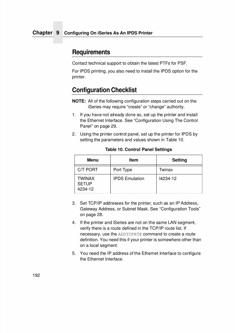
7/23/2019 54458302 IBM 6400
http://slidepdf.com/reader/full/54458302-ibm-6400 194/349
Chapter 9 Configuring On iSeries As An IPDS Printer
192
Requirements
Contact technical support to obtain the latest PTFs for PSF.
For IPDS printing, you also need to install the IPDS option for theprinter.
Configuration Checklist
NOTE: All of the following configuration steps carried out on theiSeries may require “create” or “change” authority.
1. If you have not already done so, set up the printer and installthe Ethernet Interface. See “Configuration Using The ControlPanel” on page 29.
2. Using the printer control panel, set up the printer for IPDS bysetting the parameters and values shown in Table 10.
3. Set TCP/IP addresses for the printer, such as an IP Address,Gateway Address, or Subnet Mask. See “Configuration Tools”on page 28.
4. If the printer and iSeries are not on the same LAN segment,verify there is a route defined in the TCP/IP route list. If
necessary, use the ADDTCPRTE command to create a routedefinition. You need this if your printer is somewhere other thanon a local segment.
5. You need the IP address of the Ethernet Interface to configurethe Ethernet Interface.
Table 10. Control Panel Settings
Menu Item Setting
C/T PORT Port Type Twinax
TWINAXSETUP4234-12
IPDS Emulation I4234-12
7/23/2019 54458302 IBM 6400
http://slidepdf.com/reader/full/54458302-ibm-6400 195/349
Configuration Checklist
193
6. If you have not done so yet, create a line description for your
Ethernet Interface. See “Developing Line Descriptions WithCRTLINETH” on page 175.
7. Create or verify the existence of an iSeries TCP/IP interface forthe Ethernet Interface. See “Configuring An iSeries TCP/IPInterface With ADDTCPIFC” on page 194.
8. The next step depends on your iSeries release. See“Configuring PSF For IPDS On V3R7 Or V4R1” on page 196 toconfigure your printer.
NOTE: When the IPDS feature is installed, the queue name ‘d4prn’
is not available.9. Verify the printer is ON using the VFYCFG command.
10. Verify that TCP/IP has been started using the STRTCP command.
11. Test your configuration. See “Verifying The IPDS ConfigurationOn iSeries” on page 209.
12. To share the printer on the network, verify that the necessaryparameters have been set correctly. See “Sharing The iSeriesPrinter On The Network” on page 211.
13. If you have problems, refer to “iSeries Troubleshooting” onpage 213.
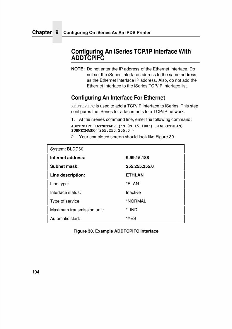
7/23/2019 54458302 IBM 6400
http://slidepdf.com/reader/full/54458302-ibm-6400 196/349
Chapter 9 Configuring On iSeries As An IPDS Printer
194
Configuring An iSeries TCP/IP Interface With
ADDTCPIFC
NOTE: Do not enter the IP address of the Ethernet Interface. Donot set the iSeries interface address to the same addressas the Ethernet Interface IP address. Also, do not add theEthernet Interface to the iSeries TCP/IP interface list.
Configuring An Interface For Ethernet
ADDTCPIFC is used to add a TCP/IP interface to iSeries. This stepconfigures the iSeries for attachments to a TCP/IP network.
1. At the iSeries command line, enter the following command:
ADDTCPIFC INTNETADR ('9.99.15.188') LIND(ETHLAN)SUBNETMASK('255.255.255.0')
2. Your completed screen should look like Figure 30.
Figure 30. Example ADDTCPIFC Interface
System: BLDD60
Internet address: 9.99.15.188
Subnet mask: 255.255.255.0
Line description: ETHLAN
Line type: *ELAN
Interface status: Inactive
Type of service: *NORMAL
Maximum transmission unit: *LIND
Automatic start: *YES
7/23/2019 54458302 IBM 6400
http://slidepdf.com/reader/full/54458302-ibm-6400 197/349
Configuring An iSeries TCP/IP Interface With ADDTCPIFC
195
3. The following parameters must be specified:
a. Internet Address
Internet address of the iSeries Ethernet LAN adapter.
NOTE:Do not use the IP address of the Ethernet Interface.
b. Subnet Mask
The Subnet Mask for this iSeries TCP/IP interface (forexample, 255.255.255.0).
c. Line Description
The name assigned to the iSeries line description asdescribed in “Developing Line Descriptions WithCRTLINETH” on page 175. Each iSeries LAN adapter willhave its own line description.
Configuring A TCP/IP Host Table Entry
Although optional, it is recommended that you create a TCP/IP hosttable entry. Add the iSeries name and the IP address of the LANadapter to the “Host Table Entries.” Also, add the hostname and IPaddress of the printer to the list. You can access the host table
entries function by using the CFGTCP command, then selectingoption 10 from the menu.
You can also add entries to your host table for both the hostnameand the fully qualified network name for your system. The entryname should match the name you configured for host and domain.For example, if your hostname is “RCHASM03” and your domainname is “RCHLAND.IBM.COM”, your fully qualified network nameis “RCHASM03.RCHLAND.IBM.COM”. In your host entry table,enter both RCHASM03 and RCHASM03.RCHLAND.IBM.COM.
7/23/2019 54458302 IBM 6400
http://slidepdf.com/reader/full/54458302-ibm-6400 198/349
Chapter 9 Configuring On iSeries As An IPDS Printer
196
Configuring PSF For IPDS On V3R7 Or V4R1
To configure IPDS on iSeries V3R7 and above, use the followingcommands:
• CRTPSFCFG (Optional)
• CRTDEVPRT
Configuring AFP With CRTPSFCFG On V3R7 OrV4R1 (Optional)
New for V3R7 is the ability to specify three TCP/IP-related
parameters for PSF in a printer device description: RMTLOCNAME,PORT, and ACTTMR. In V3R2, CRTPSFCFG, which replacedWRKAFP2, was used to specify these same parameters, along withother parameters. In V3R7 and higher, these three parameters areignored when specified in a PSF configuration object, since theyare specified in a printer device description. However, you maywish to use a PSF configuration object to specify other parameters,such as IPDS pass through and so on.
The PSF configuration object created with this command is used byPSF when printing IPDS files only if the object is specified with theUSRDFNOBJ parameter in the printer device description.
To configure iSeries for IPDS printing on V3R7 or V4R1:
1. At the iSeries command line, enter a command in the form:
CRTPSFCFG PSFCFG(AFP/NET6400IPDSPASTHR(*YES) RLSTMR(*SEC15)TEXT(‘ printer_type NETWORK PRINTER’)
2. A completed screen looks like Figure 31.
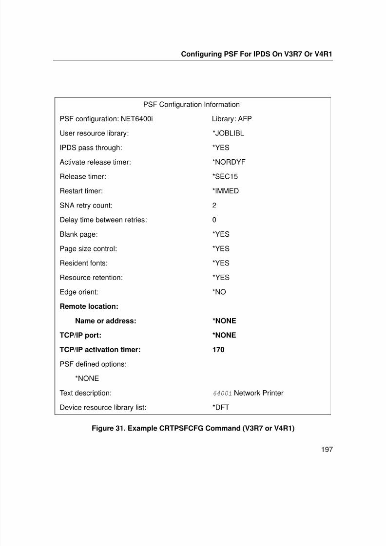
7/23/2019 54458302 IBM 6400
http://slidepdf.com/reader/full/54458302-ibm-6400 199/349
Configuring PSF For IPDS On V3R7 Or V4R1
197
Figure 31. Example CRTPSFCFG Command (V3R7 or V4R1)
PSF Configuration Information
PSF configuration: NET6400i Library: AFP
User resource library: *JOBLIBL
IPDS pass through: *YES
Activate release timer: *NORDYF
Release timer: *SEC15
Restart timer: *IMMED
SNA retry count: 2
Delay time between retries: 0
Blank page: *YES
Page size control: *YES
Resident fonts: *YES
Resource retention: *YES
Edge orient: *NO
Remote location:
Name or address: *NONE
TCP/IP port: *NONE
TCP/IP activation timer: 170
PSF defined options:
*NONEText description: 6400i Network Printer
Device resource library list: *DFT
7/23/2019 54458302 IBM 6400
http://slidepdf.com/reader/full/54458302-ibm-6400 200/349
Chapter 9 Configuring On iSeries As An IPDS Printer
198
NOTE: The lines in bold in Figure 31 are not used by PSF.
Instead, PSF uses the information entered in the devicedescription screen.
3. The following parameters are recommended:
a. PSF configuration (PSFCFG)
The name used for this PSF configuration object. Thename must match the user-defined object name(USRDFNOBJ) in the printer DEVD.
b. IPDS pass through (IPDSPASTHR)
To print SCS files, specify *YES, PSF transforms SCS intoIPDS before printing.
c. Activate release timer (ACTRLSTMR)
Specifies the point at which the release timer (RLSTMR) isactivated. Set to *NORDYF.
d. Release timer (RLSTMR)
Specifies the amount of time to wait before a session ordialog is released without terminating the writer. TheACTRLSTMR parameter specifies when this timer is to be
activated. Set the parameter to a value at least equal to theTIMEOUT value on the printer. The recommended value is*SEC15.
e. Page Size Control (PAGSIZCTL)
Specifies if the page size (FORMS) is set by PSF.400.Usually set to *YES.
7/23/2019 54458302 IBM 6400
http://slidepdf.com/reader/full/54458302-ibm-6400 201/349
Configuring PSF For IPDS On V3R7 Or V4R1
199
Configuring PSF With CRTDEVPRT On V3R7 Or
V4R1This section describes how to create a printer device description.
1. At the iSeries command line, enter a command in the form:
CRTDEVPRT DEVD(NETPRT64) DEVCLS(*LAN) TYPE(*IPDS) MODEL(0) LANATTACH(*IP) AFP(*YES) PORT(5001)FONT(11) FORMFEED(*CONT)RMTLOCNAME(‘128.9.12.134’)USRDFNOBJ(AFP/5000NETPRT *PSFCFG)TEXT(‘ printer_type NETWORK PRINTER’)
NOTE: Only use the USRDFNOBJ parameter if it was defined in
the previous procedure. See “Configuring AFP WithCRTPSFCFG On V3R7 Or V4R1 (Optional)” on page 196.
2. A completed screen looks like the example shown in Figure 32.
Display Device Description
5716SS1 V3R7M0 961108 BLDRB1
Device Description: DEVD NETPRT64
Option: OPTION *ALL
Category of device: *PRT
Device class: DEVCLS *LAN
Device type: TYPE *IPDS
Device model: MODEL 0
LAN attachment: LANATTACH *IP
User-defined object: USRDFNOBJ NET6400i
Library: AFP
Object type: *PSFCFG
Data transform program: USRDTATFM *NONE
User-defined driver program: USRDRVPGM *NONE
Advanced function printing: AFP *YES
7/23/2019 54458302 IBM 6400
http://slidepdf.com/reader/full/54458302-ibm-6400 202/349
Chapter 9 Configuring On iSeries As An IPDS Printer
200
Figure 32. Example CRTDEVPRT Command (V3R7 and above)
Port number: PORT 5001
Online at IPL: ONLINE *YES
Font: FONT
Identifier: 011
Point size: *NONE
Form feed: FORMFEED *CONT
Separator drawer: SEPDRAWER *FILE
Separator program: SEPPGM *NONELibrary:
Printer error message: PRTERRMSG *INQ
Message queue: MSGQ QSYSOPR
Library: *LIBL
Activation timer: ACTTMR 170
Maximum pending requests: MAXPNDRQS 6
Print while converting: PRTCVT *YES
Print request timer: PRTRQSTMR *NOMAX
Form definition: FORMDF F1C10110
Library: *LIBL
Remote location: RMTLOCNAME
Name or address: 128.9.12.134
Dependent location name: DEPLOCNAME *NONEText: TEXT 6400i Network Printer
User-defined options: USRDFNOPT
7/23/2019 54458302 IBM 6400
http://slidepdf.com/reader/full/54458302-ibm-6400 203/349
Configuring PSF For IPDS On V3R7 Or V4R1
201
3. Values must be entered for the following parameters:
a. Device Description (DEVD)
The device description or name.
b. Device Class (DEVCLS)
Specify *LAN
c. Device Type (TYPE)
Specify *IPDS
d. Device Model (MODEL)
Specify 0e. LAN Attachment (LANATTACH)
Specify *IP
f. Port Number (PORT)
Specify 5001
g. Font (FONT)
Enter an appropriate value.
h. Form Feed (FORMFEED)
Specify *CONT
i. Activation Timer (ACTTMR)
This value specifies the number of seconds that PSF waitsfor a printer to respond to an activation request. If only onesystem is using the printer, use the default value (170seconds). If more than one system is using the printer,specify *NOMAX, which causes PSF to wait indefinitely for aresponse to an activation request.
j. Remote Location (RMTLOCNAME)Enter the IP address or hostname of the printer.
7/23/2019 54458302 IBM 6400
http://slidepdf.com/reader/full/54458302-ibm-6400 204/349
Chapter 9 Configuring On iSeries As An IPDS Printer
202
k. User-Defined Object (USRDFNOBJ)
To use a PSF configuration object, specify its name andlibrary here. This object type must be *PSFCFG. For V3R7and higher, a single PSF configuration object may bereferenced by multiple device descriptions, if required.
Configuring PSF for IPDS On V4R2 And Above
To configure IPDS on the iSeries V4R3, use the followingcommands:
• CRTDEVPRT• CRTPSFCFG (Optional)
Configuring AFP with CRTPSFCFG on V4R3 andabove (Optional)
To configure the iSeries for IPDS printing on V4R3:
1. At the iSeries command line, enter a command in the form:
CRTPSFCFG PSFCFG(AFP/NETPRT6400i) IPDSPASTHR(*YES)RLSTMR(*SEC15) TEXT(‘IBM 6400i NETWORK ATTACHED
PRINTER’) PAGSIZCTL(*YES) ACTRLSTMR(*NORDYF)2. A completed screen looks like Figure 33.
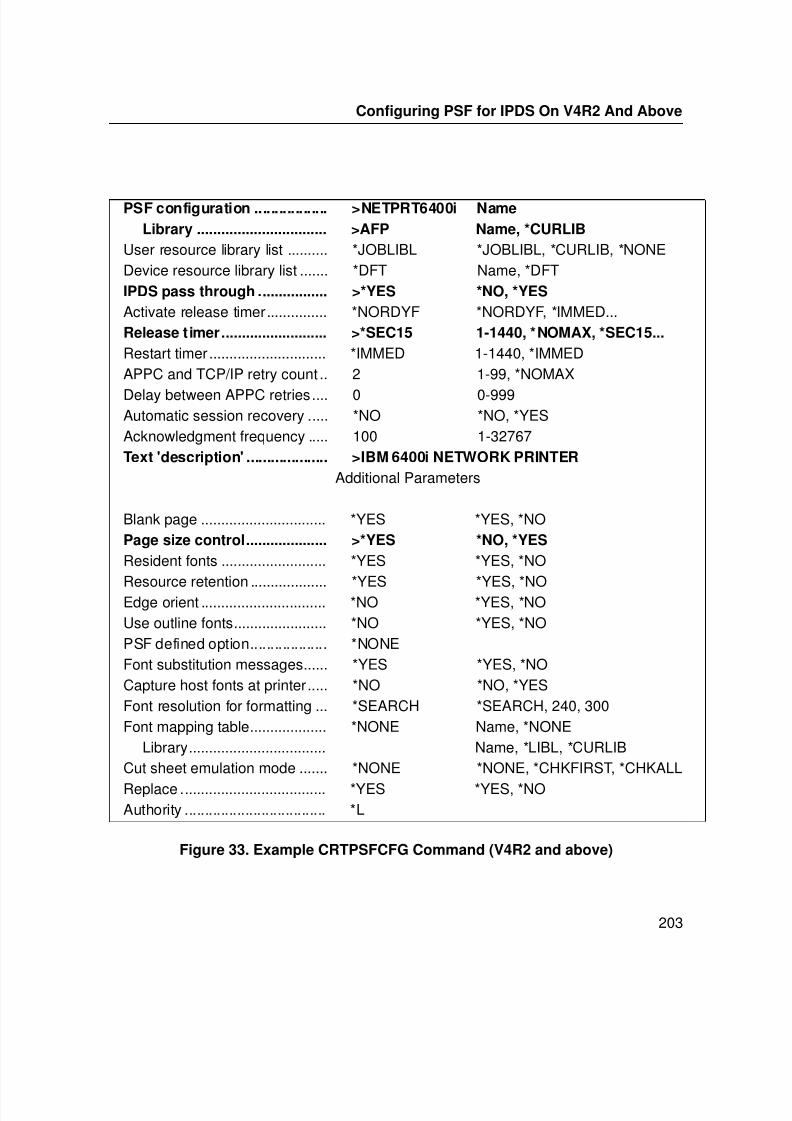
7/23/2019 54458302 IBM 6400
http://slidepdf.com/reader/full/54458302-ibm-6400 205/349
7/23/2019 54458302 IBM 6400
http://slidepdf.com/reader/full/54458302-ibm-6400 206/349
Chapter 9 Configuring On iSeries As An IPDS Printer
204
3. The following parameters are recommended: PSF
configuration (PSFCFG)The name used for this PSF configuration object. The name mustmatch the user-defined object name (USRDFNOBJ) in the printerDEVD.
PSF configuration (PSFCFG)
The name used for this PSF configuration object. The name mustmatch the user-defined object name (USRDFNOBJ) in the printerDEVD.
IPDS pass through (IPDSPASTHR)
To print SCS files, specify *YES, PSF transforms SCS into IPDSbefore printing.
Release timer (RLSTMR)
Specifies the amount of time to wait before a session or dialog isreleased without terminating the writer. The ACTRLSTMRparameter specifies when this timer is to be activated. Set theparameter to a value at least equal to the TIMEOUT value on the
printer. IBM recommends *SEC15.
Page size control (PAGSIZCTL)
Specifies if the page size (forms) is set by PSF. Usually set to*YES.
Remote Location name or address (RMTLOCNAME)
Enter the IP address or hostname of the printer.
7/23/2019 54458302 IBM 6400
http://slidepdf.com/reader/full/54458302-ibm-6400 207/349
Configuring PSF for IPDS On V4R2 And Above
205
Configuring PSF with CRTDEVPRT On V4R2 and
aboveThis section describes how to create a printer device description.
1. At the iSeries command line, enter a command in the form:
Only use the USRDFNOBJ parameter if it was defined in theprevious procedure.
A completed screen looks like the example shown in Figure 34.
CRTDEVPRT DEVD(P6400i) DEVCLS(*LAN) TYPE(*IPDS) MODEL(0)
LANATTACH(*IP) AFP(*YES) PORT(5001) FONT(11)FORMFEED(*CONT) RMTLOCNAME(‘128.9.12.134’)
USRDFNOBJ(AFP/NETPRT6400i *PSFCFG)
TEXT(‘IBM 6400i NETWORK PRINTER’)
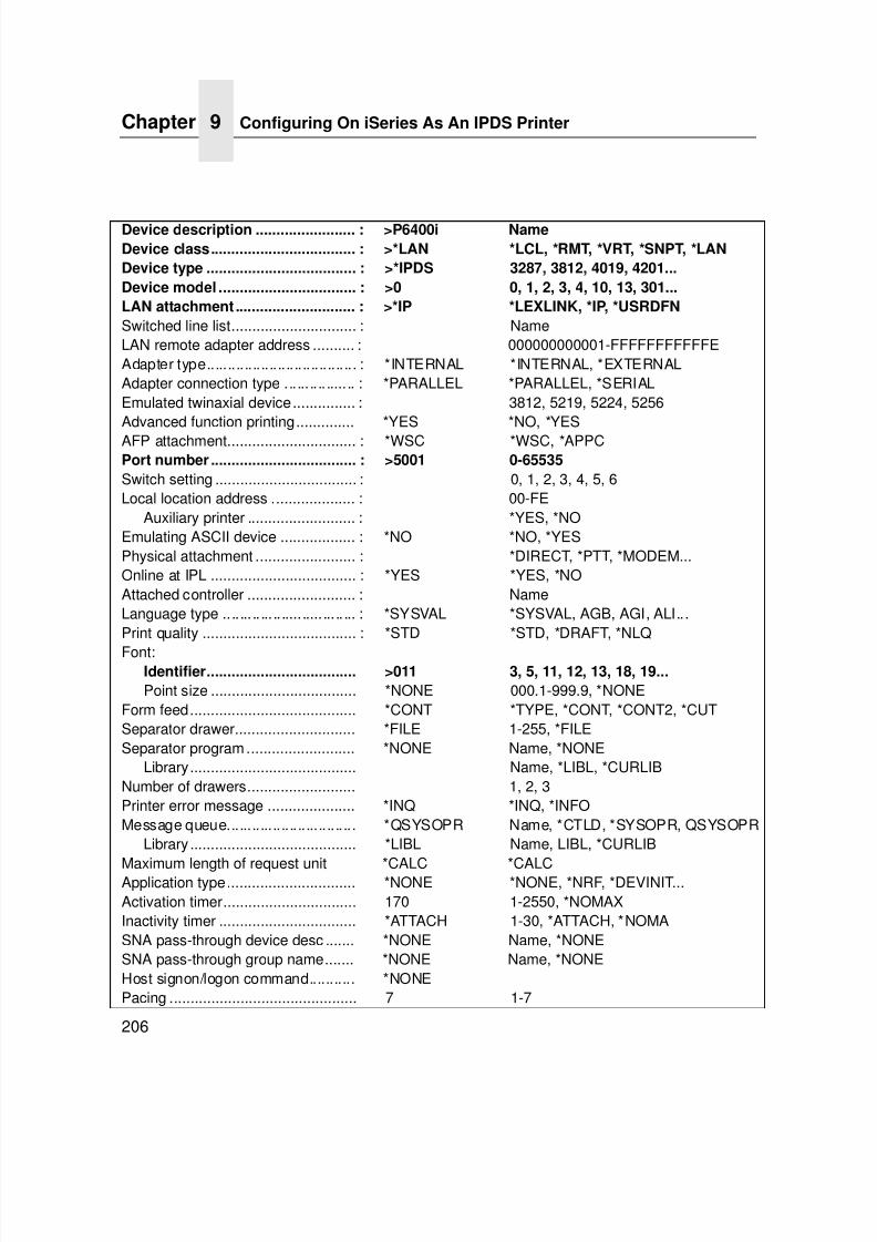
7/23/2019 54458302 IBM 6400
http://slidepdf.com/reader/full/54458302-ibm-6400 208/349
Chapter 9 Configuring On iSeries As An IPDS Printer
206
Device description ........................ : >P6400i Name
Device class................................... : >*LAN *LCL, *RMT, *VRT, *SNPT, *LAN
Device type .................................... : >*IPDS 3287, 3812, 4019, 4201...
Device model ................................. : >0 0, 1, 2, 3, 4, 10, 13, 301...
LAN attachment ............................. : >*IP *LEXLINK, *IP, *USRDFN
Switched line list.............................. : NameLAN remote adapter address .......... : 000000000001-FFFFFFFFFFFEAdapter type.................................... : *INTERNAL *INTERNAL, *EXTERNALAdapter connection type ................. : *PARALLEL *PARALLEL, *SERIALEmulated twinaxial device............... : 3812, 5219, 5224, 5256Advanced function printing.............. *YES *NO, *YES
AFP attachment............................... : *WSC *WSC, *APPCPort number ................................... : >5001 0-65535
Switch setting .................................. : 0, 1, 2, 3, 4, 5, 6Local location address .................... : 00-FE
Auxiliary printer .......................... : *YES, *NOEmulating ASCII device .................. : *NO *NO, *YESPhysical attachment ........................ : *DIRECT, *PTT, *MODEM...Online at IPL ................................... : *YES *YES, *NOAttached controller .......................... : NameLanguage type ................................ : *SYSVAL *SYSVAL, AGB, AGI, ALI...Print quality ..................................... : *STD *STD, *DRAFT, *NLQ
Font:Identifier.................................... >011 3, 5, 11, 12, 13, 18, 19...
Point size ................................... *NONE 000.1-999.9, *NONEForm feed........................................ *CONT *TYPE, *CONT, *CONT2, *CUTSeparator drawer............................. *FILE 1-255, *FILESeparator program.......................... *NONE Name, *NONE
Library........................................ Name, *LIBL, *CURLIBNumber of drawers.......................... 1, 2, 3Printer error message ..................... *INQ *INQ, *INFOMessage queue............................... *QSYSOPR Name, *CTLD, *SYSOPR, QSYSOPR
Library ........................................ *LIBL Name, LIBL, *CURLIB
Maximum length of request unit *CALC *CALCApplication type............................... *NONE *NONE, *NRF, *DEVINIT...Activation timer................................ 170 1-2550, *NOMAXInactivity timer ................................. *ATTACH 1-30, *ATTACH, *NOMASNA pass-through device desc ....... *NONE Name, *NONESNA pass-through group name....... *NONE Name, *NONEHost signon/logon command........... *NONEPacing ............................................. 7 1-7
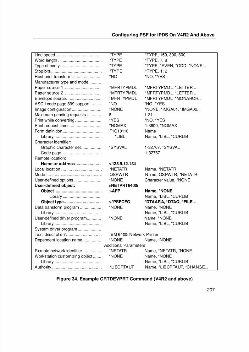
7/23/2019 54458302 IBM 6400
http://slidepdf.com/reader/full/54458302-ibm-6400 209/349
Configuring PSF for IPDS On V4R2 And Above
207
Figure 34. Example CRTDEVPRT Command (V4R2 and above)
Line speed....................................... *TYPE *TYPE, 150, 300, 600
Word length . .................................... *TYPE *TYPE, 7, 8Type of parity................................... *TYPE *TYPE, *EVEN, *ODD, *NONE...Stop bits ........................................... *TYPE *TYPE, 1, 2Host print transform ......................... *NO *NO, *YESManufacturer type and model..........Paper source 1................................ *MFRTYPMDL *MFRTYPMDL, *LETTER...Paper source 2................................ *MFRTYPMDL *MFRTYPMDL, *LETTER...Envelope source.............................. *MFRTYPMDL *MFRTYPMDL, *MONARCH...ASCII code page 899 support ......... *NO *NO, *YESImage configuration......................... *NONE *NONE, *IMGA01, *IMGA02...Maximum pending requests ............ 6 1-31Print while converting ...................... *YES *NO, *YESPrint request timer ........................... *NOMAX 1-3600, *NOMAXForm definition................................. F1C10110 Name
Library ........................................ *LIBL Name, *LIBL, *CURLIBCharacter identifier:
Graphic character set ................. *SYSVAL 1-32767, *SYSVALCode page.................................. 1-32767
Remote location:Name or address ...................... >128.9.12.134
Local location...................................: *NETATR Name, *NETATRMode................................................ QSPWTR Name, QSPWTR, *NETATRUser-defined options ....................... *NONE Character value, *NONEUser-defined object: >NETPRT6400i
Object ........................................ >AFP Name, *NONE
Library ................................. Name, *LIBL, *CURLIBObject type................................ >*PSFCFG *DTAARA, *DTAQ, *FILE...
Data transform program .................. *NONE Name, *NONELibrary ........................................ Name, *LIBL, *CURLIB
User-defined driver program............ *NONE Name, *NONELibrary ........................................ Name, *LIBL, *CURLIB
System driver program ....................Text ‘description’.............................. IBM 6400i Network PrinterDependent location name................ *NONE Name, *NONE
Additional ParametersRemote network identifier................ *NETATR Name, *NETATR, *NONEWorkstation customizing object ....... *NONE Name, *NONE
Library ........................................ Name, *LIBL, *CURLIBAuthority .......................................... *LIBCRTAUT Name, *LIBCRTAUT, *CHANGE...
7/23/2019 54458302 IBM 6400
http://slidepdf.com/reader/full/54458302-ibm-6400 210/349
Chapter 9 Configuring On iSeries As An IPDS Printer
208
2. Values must be entered for the following parameters:
Device Description (DEVD)
The device description or name.
Device Class (DEVCLS)
Specify *LAN.
Device Type (TYPE)
Specify *IPDS.
Device Model (MODEL)
Specify 0.
LAN attachment (LANATTACH)
Specify *IP.
Port number (PORT)
Specify 5001.
Font (FONT)
Enter an appropriate value.
Form Feed (FORMFEED)
Specify *CONT.
Activation timer (ACTTMR)
This value specifies the number of seconds that PSF waits for aprinter to respond to an activation request. If only one system isusing the printer, use the default value (170 seconds). If more thanone system is using the printer, specify *NOMAX, which causesPSF to wait indefinitely for a response to an activation request.
7/23/2019 54458302 IBM 6400
http://slidepdf.com/reader/full/54458302-ibm-6400 211/349
Configuring PSF for IPDS On V4R2 And Above
209
Remote Location (RMTLOCNAME)
Enter the IP address or hostname of the printer.
User-Defined Object (USRDFNOBJ)
To use a PSF configuration object, specify its name and libraryhere. This object type must be *PSFCFG. For V3R7 and higher, asingle PSF configuration object may be referenced by multipledevice descriptions, if required.
Verifying The IPDS Configuration On iSeriesTo test IPDS printing:
1. If it is not already on, vary on the line description: VRYCFG CFGTYPE(*LIN)
2. To start TCP/IP, enter STRTCP.
3. Verify that the iSeries TCP/IP interface is active. Use thecommand:
WRKTCPSTS
and then select option 1.
4. Turn the printer on and wait until the printer control paneldisplays “ETHERNET ADAPTER IS READY.”
Verifying The IPDS Configuration On iSeries
7/23/2019 54458302 IBM 6400
http://slidepdf.com/reader/full/54458302-ibm-6400 212/349
Chapter 9 Verifying The IPDS Configuration On iSeries
210
5. To verify the printer is connected to iSeries, ping the printer
from an iSeries workstation with one of the followingcommands:PING ip_address
orPING hostname
where ip_address is the Internet address of the remotesystem printer (the Ethernet Interface), and hostname is thehostname you defined for the printer, if any.
• If the ping is not successful, refer to “Cannot PING The
Printer” on page 213.• If the ping is successful, vary on the printer device
description with the command: VRYCFG ( printer_device) CFGTYPE(*DEV)
STATUS(*ON)
6. To use PSF to send an IPDS file to the printer, enter:STRPRTWTR DEV ( printer_device)
where printer_device is the name of the printer.
7. If you have problems printing, do the following:
• Print an Ethernet Test Page. Refer to your User's Manual .
• Verify that port number 5001 is being used.
8. If you are still unable to print IPDS files, contact technicalsupport.
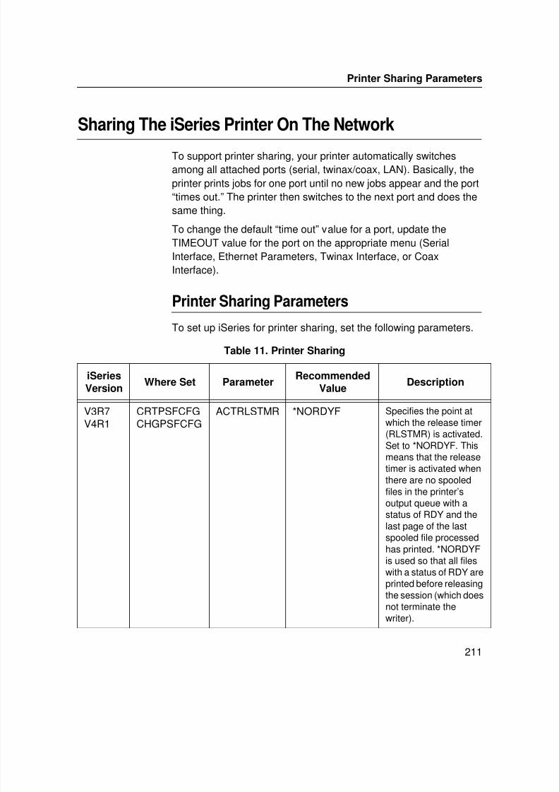
7/23/2019 54458302 IBM 6400
http://slidepdf.com/reader/full/54458302-ibm-6400 213/349
Printer Sharing Parameters
211
Sharing The iSeries Printer On The Network
To support printer sharing, your printer automatically switchesamong all attached ports (serial, twinax/coax, LAN). Basically, theprinter prints jobs for one port until no new jobs appear and the port“times out.” The printer then switches to the next port and does thesame thing.
To change the default “time out” value for a port, update theTIMEOUT value for the port on the appropriate menu (SerialInterface, Ethernet Parameters, Twinax Interface, or CoaxInterface).
Printer Sharing Parameters
To set up iSeries for printer sharing, set the following parameters.
Table 11. Printer Sharing
iSeriesVersion
Where Set ParameterRecommended
ValueDescription
V3R7V4R1 CRTPSFCFGCHGPSFCFG ACTRLSTMR *NORDYF Specifies the point atwhich the release timer(RLSTMR) is activated.Set to *NORDYF. Thismeans that the releasetimer is activated whenthere are no spooledfiles in the printer’soutput queue with astatus of RDY and thelast page of the lastspooled file processed
has printed. *NORDYFis used so that all fileswith a status of RDY areprinted before releasingthe session (which doesnot terminate thewriter).
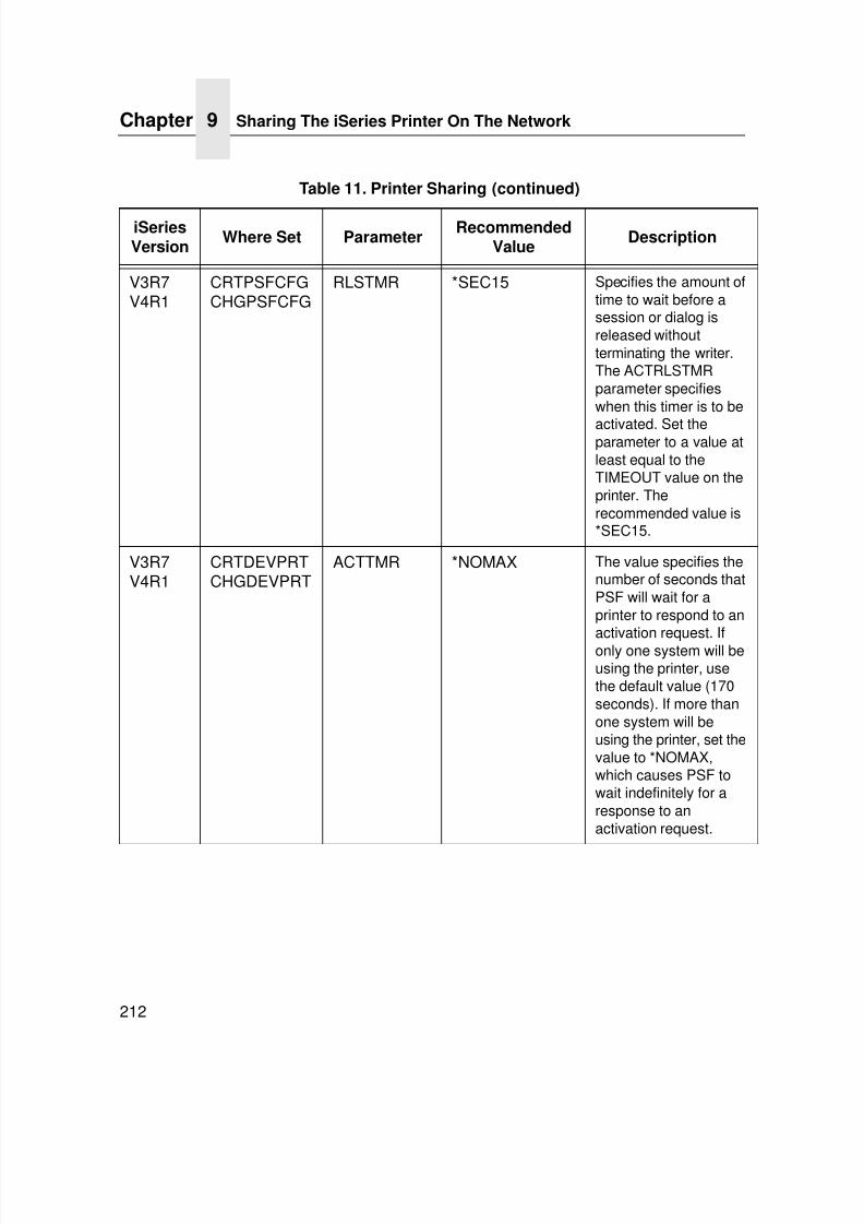
7/23/2019 54458302 IBM 6400
http://slidepdf.com/reader/full/54458302-ibm-6400 214/349
Chapter 9 Sharing The iSeries Printer On The Network
212
V3R7V4R1
CRTPSFCFGCHGPSFCFG
RLSTMR *SEC15 Specifies the amount oftime to wait before asession or dialog isreleased withoutterminating the writer.The ACTRLSTMRparameter specifieswhen this timer is to be
activated. Set theparameter to a value atleast equal to theTIMEOUT value on theprinter. Therecommended value is*SEC15.
V3R7V4R1
CRTDEVPRTCHGDEVPRT
ACTTMR *NOMAX The value specifies thenumber of seconds thatPSF will wait for aprinter to respond to an
activation request. Ifonly one system will beusing the printer, usethe default value (170seconds). If more thanone system will beusing the printer, set thevalue to *NOMAX,which causes PSF towait indefinitely for aresponse to anactivation request.
Table 11. Printer Sharing (continued)
iSeriesVersion
Where Set ParameterRecommended
ValueDescription
7/23/2019 54458302 IBM 6400
http://slidepdf.com/reader/full/54458302-ibm-6400 215/349
Cannot PING The Printer
213
iSeries Troubleshooting
Use this section to resolve problems configuring iSeries on TCP/IPnetworks.
Cannot PING The Printer
If you have problems trying to ping the printer:
• Verify the configuration of iSeries, including the printer and anyintervening devices such as routers and bridges.
• Verify that the iSeries line description is varied on and theprinter is turned on and displays a status of ONLINE.
• Verify that the iSeries TCP/IP interface is active.
PSF Terminates When Initialized
If PSF terminates when you initialize it for IPDS printing and issuesmessage PQT3603, check for the following error codes:
• Code 10 means an incorrect RMTSYS or RMTLOCNAME (V3R2,
V3R7, or V4R1) has been specified for the printer.• Code 15 means that PSF timed out waiting for the printer’s
response. Check the value you entered for Activation Timerwhen using WRKAFP2, CRTPSFCFG (V3R2), or CRTDEVPRT (V3R7 or V4R1).
• Codes 20-39 indicate a general communications failure. Makesure all of the components in your network are operational,such as routers. If necessary, call IBM technical support.
• Codes 40-59 indicate a logic error between PSF and the printer
control unit. Contact IBM technical support.
iSeries Troubleshooting
7/23/2019 54458302 IBM 6400
http://slidepdf.com/reader/full/54458302-ibm-6400 216/349
Chapter 9 iSeries Troubleshooting
214
Spooled Print File Remains In PND Status
Check the output queue with the command:
WRKOUTQ queuename
This typically indicates that PSF is waiting for a response from theprinter. This can be verified by displaying the QSPL subsystem,WRKACTJOBSBS (QSPL). If the status of the PDJ job for the printeris SELW, then PSF is waiting for a response from the printer. Makesure that the printer is in ONLINE mode and that all networkconnections (for example, routers) between the iSeries and theprinter are active.
Spooled Files Disappear Without Printing
To resolve this problem:
• Check that the correct printer queue name and correct IPaddress have been used.
• Ping the IP address. If the ping is successful, disconnect thenetwork cable from the printer/print server, and ping theaddress again. If the ping is still successful, there is another
printer with that IP address on the network.
Data Is Being Clipped
To resolve this problem, you may want to set the PSC (Page SizeControl) parameter to *YES in the CRTPSFCFG command (V3R2,V3R7, or V4R1).
7/23/2019 54458302 IBM 6400
http://slidepdf.com/reader/full/54458302-ibm-6400 217/349
215
10 z/OS Configuration for an IPDS Printer
OverviewUse this chapter to configure z/OS to print IPDS files on your IBM4400/6400i network printer.
To print IPDS files, you must have the IPDS option on the printer.
Requirements
Verify that you have the following required software:
• PSF Version 2.2.0 with APAR OW15599 (for TCP/IP support)
• z/OS Scheduler with APAR OW12236 to support two newPRINTDEV keywords: IPADDR and PORTNO
• TCP/IP Version 3 Release 1, or higher, installed and configuredon z/OS
To obtain the PTFs associated with these APARs, contact the IBMSupport Center.
7/23/2019 54458302 IBM 6400
http://slidepdf.com/reader/full/54458302-ibm-6400 218/349
Chapter 10 Overview
216
Configuration Checklist
All of the following configuration steps carried out on z/OS requireappropriate RACF authority.
1. Using the printer operator panel, set up the IPDS printeremulation to 6408/6412.
2. Set TCP/IP addresses for the printer, such as IP address,gateway address, or subnet mask. See “Configuration Tools”on page 28.
3. Configure the host environment.
See “Configuring PSF for z/OS to Print IPDS Files” onpage 217.
4. Verify the configuration. See “Verifying a TCP/IP-AttachedPrinter on z/OS” on page 227.
5. If you want to share the printer, do the procedure in “SharingIBM 6400i Printers on z/OS” on page 228.
6. If you have problems, refer to “Handling z/OS ConnectivityProblems” on page 230.
7/23/2019 54458302 IBM 6400
http://slidepdf.com/reader/full/54458302-ibm-6400 219/349
Configuration Procedure
217
Configuring PSF for z/OS to Print IPDS Files
To perform this procedure, you need the IP address of theEthernet.
Configuration Procedure
Configuring PSF to print IPDS files includes the following steps:
1. Define the z/OS communications control unit to z/OS. See“Define the Communications Control Unit to z/OS” on page218.
2. Modify the TCP/IP profile on your z/OS system, if necessary.See “Modify the TCP/IP Profile in z/OS” on page 218.
3. “Ping” the printer. See “Verify the Printer Connection” on page221.
4. Define the printer as a writer-controlled printer to JES. See“Define the Printer to JES” on page 222.
5. Define the printer to PSF with a PRINTDEV statement,including the IP address. See “Define the Printer to PSF” on
page 223.This section does not provide all the information you need to installand configure TCP/IP on your z/OS system. For more informationon installing TCP/IP, refer to TCP/IP for z/OS: Customization and
Administration Guide .
The routing of information is determined on the basis of the IPaddress, and is performed by IP gateways. After the network isconfigured correctly, the z/OS host appears to be communicatingdirectly with the TCP/IP-attached printer.
7/23/2019 54458302 IBM 6400
http://slidepdf.com/reader/full/54458302-ibm-6400 220/349
Chapter 10 Configuring PSF for z/OS to Print IPDS Files
218
Define the Communications Control Unit to z/OS
If you have not already done so, define the communications controlunit for the z/OS host, such as the 3172 or the 3745 control unit, toz/OS. Use either an z/OS configuration program (MVSCP) or ahardware configuration definition (HCD), depending on the versionof your z/OS system:
• When using a version earlier than z/OS 4.1.0, use an MVSCP.
• When using a version of z/OS 4.1.0 or later, use an HCD or anMVSCP.
For more information about using these methods, refer to:
• MVS/ESA* Migration Planning: Dynamic I/O Configuration
• MVS/ESA Hardware Configuration: Using the Dialog
Modify the TCP/IP Profile in z/OS
The TCP/IP profile contains system configuration statements usedto initialize the TCP/IP address space. Of those statements, thefollowing are subject to special considerations when you areprinting from PSF on TCP/IP-attached printers. Samples of thesestatements are printed in bold in the example shown in Figure 35.
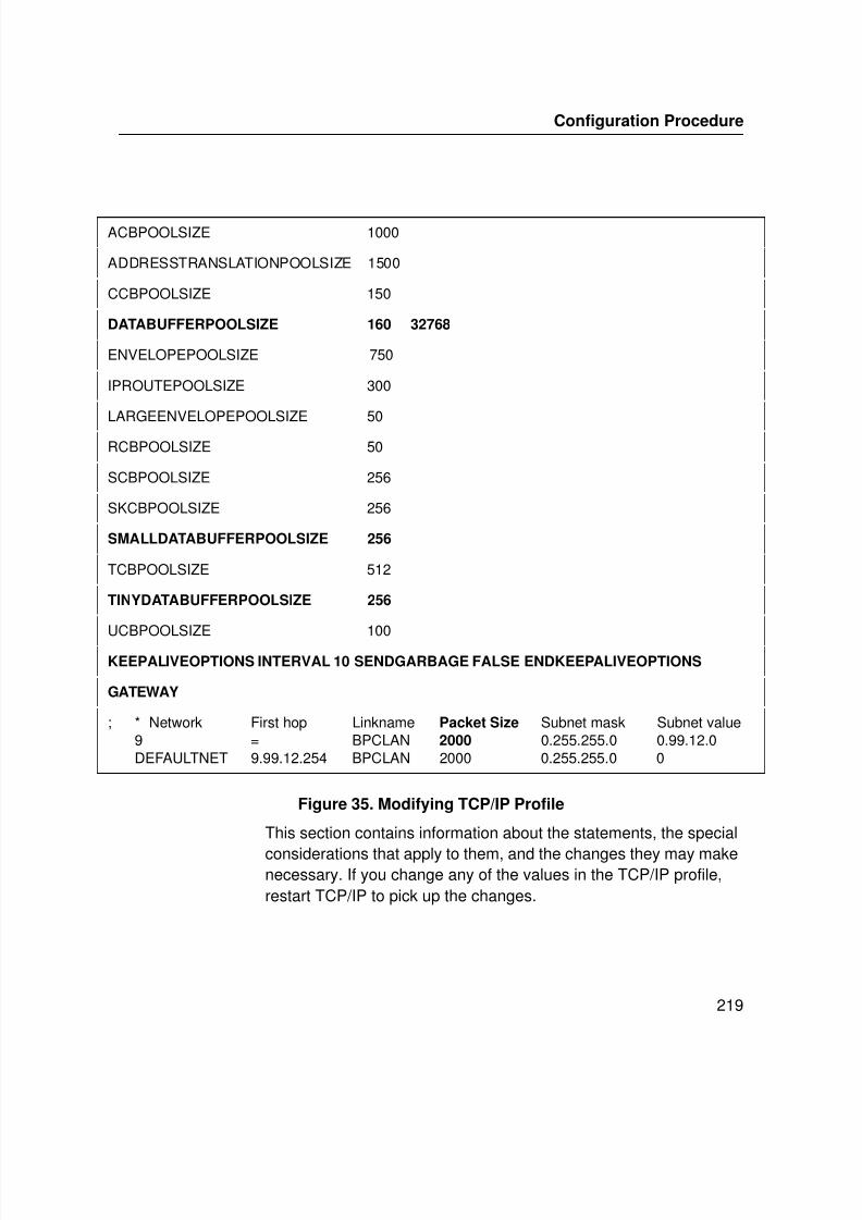
7/23/2019 54458302 IBM 6400
http://slidepdf.com/reader/full/54458302-ibm-6400 221/349
Configuration Procedure
219
Figure 35. Modifying TCP/IP Profile
This section contains information about the statements, the special
considerations that apply to them, and the changes they may makenecessary. If you change any of the values in the TCP/IP profile,restart TCP/IP to pick up the changes.
ACBPOOLSIZE 1000
ADDRESSTRANSLATIONPOOLSIZE 1500
CCBPOOLSIZE 150
DATABUFFERPOOLSIZE 160 32768
ENVELOPEPOOLSIZE 750
IPROUTEPOOLSIZE 300
LARGEENVELOPEPOOLSIZE 50
RCBPOOLSIZE 50
SCBPOOLSIZE 256
SKCBPOOLSIZE 256
SMALLDATABUFFERPOOLSIZE 256
TCBPOOLSIZE 512
TINYDATABUFFERPOOLSIZE 256
UCBPOOLSIZE 100KEEPALIVEOPTIONS INTERVAL 10 SENDGARBAGE FALSE ENDKEEPALIVEOPTIONS
GATEWAY
; * Network First hop Linkname Packet Size Subnet mask Subnet value9 = BPCLAN 2000 0.255.255.0 0.99.12.0DEFAULTNET 9.99.12.254 BPCLAN 2000 0.255.255.0 0
7/23/2019 54458302 IBM 6400
http://slidepdf.com/reader/full/54458302-ibm-6400 222/349
Chapter 10 Configuring PSF for z/OS to Print IPDS Files
220
For information about the TCP/IP profile and the statements
described in this section, refer to:• IBM TCP/IP z/OS Customization and Administration Guide
• IBM TCP/IP Performance and Tuning Guide
DATABUFFERPOOLSIZE
The DATABUFFERPOOLSIZE statement defines the number andsize of the data buffers. For printing on TCP/IP-attached printers,IBM recommends that you specify at least 160 data buffers, 32768 buffer size.
SMALLDATABUFFERPOOLSIZE
The SMALLDATABUFFERPOOLSIZE statement defines thenumber of small data buffers. For printing on TCP/IP-attachedprinters, IBM recommends that you specify at least 256 small databuffers.
TINYDATABUFFERPOOLSIZE
The TINYDATABUFFERPOOLSIZE statement defines the number
of tiny data buffers. For printing on TCP/IP-attached printers, IBMrecommends that you specify at least 256 tiny data buffers.
KEEPALIVEOPTIONS
PSF relies on TCP to detect when a connection with a TCP/IP-attached printer is no longer usable. When no data has beenexchanged between PSF and its connection partner, TCP sendskeep-alive probes to the connection partner periodically. Theseperiodic probes, called keep-alive transmissions, enable TCP todiscover when a connection is no longer usable even if the
connection partner is abruptly powered off or is no longeraccessible through the network.
The frequency of keep-alive transmissions is controlled by theINTERVAL parameter on the KEEPALIVEOPTIONS statement.The frequency applies to all TCP applications that direct TCP tosend keep-alive transmissions. The default frequency is after abouttwo hours of inactivity.

7/23/2019 54458302 IBM 6400
http://slidepdf.com/reader/full/54458302-ibm-6400 223/349
Configuration Procedure
221
For printing on TCP/IP-attached printers, IBM recommends that
you specify a shorter interval than the default, such as 10 minutes,for the interval between keep-alive transmissions.
Also, if any target host requires that the keep-alive packet containdata, specify SENDGARBAGE TRUE. For example:
KEEPALIVEOPTIONS INTERVAL 5 SENDGARBAGE TRUEENDKEEPALIVEOPTIONS
GATEWAY
The Packet Size parameter of the GATEWAY statement definesthe maximum transmission unit (MTU) for the z/OS host. For IBM
10/100Base-T Ethernet Interface printers, the MTU size is fixed at1024 bytes. The value cannot be adjusted.
Verify the Printer Connection
To verify that the z/OS system can establish a connection with theTCP/IP-attached printer, “ ping” the printer from the MVS system.
From a TSO session, enter the following command:
TSO PING ip_address
In JES2, enter the following command from the System Display andSearch Facility (SDSF) menu 6:
ping ip_address
ip_address specifies the IP address of the Ethernet.
Here is an example of a successful “ ping” command:
EZA0458I Ping V3R1: Pinging host 9.99.12.33(Use ATTN to interrupt.)EZA0463I PING: Ping #1 response took 0.084 seconds.Successes so far = 1.
Here is an example of an unsuccessful “ ping” command:
EZA0458I Ping V3R1: Pinging host 9.99.12.33(Use ATTN to interrupt.)EZA0464I PING: Ping #1 timed out
NOTE: If you have problems “ ping”-ing a printer, refer to “Handlingz/OS Connectivity Problems” on page 230.
7/23/2019 54458302 IBM 6400
http://slidepdf.com/reader/full/54458302-ibm-6400 224/349
Chapter 10 Configuring PSF for z/OS to Print IPDS Files
222
Define the Printer to JES
When a TCP/IP-attached printer is to be used with JES, it must bedefined for deferred printing mode with JES.
JES2 Printer Definitions
Below is an example of the JES2 printer definition initializationmember, located in the system PARMLIB:
FSS(FSS1),PROC=PSFPROC,HASPFSSM=HASPFSSM PRT1 FSS=FSS1,MODE=FSS,PRMODE=(LINE,PAGE,SOSI1),
CLASS=C,UCS=0,SEP,NOSEPDS,CKPTPAGE=100,DRAIN,MARK,TRKCELL=YES
The above example is correct for JES2 3.11 and above. For earlierversions of JES2, the statement is named FSSDEF and would bestated as FSSDEF FSSNAME=FSS1.
The value you specify for the PROC parameter must match thename on the PSF Startup procedure.
JES3 Printer Definitions
Below is an example JES3 printer definition. This example is notexecutable, but it is intended to help the JES3 systems programmer
define the printer to the z/OS host.FSSDEF,TYPE=WTR,FSSNAME=FSS1,PNAME=PSFPROC,SYSTEM=SYS1,TERM=NO DEVICE,JNAME=PRT1,JUNIT=(,SYS1,,OFF),FSSNAME=FSS1, MODE=FSS,PM=(LINE,PAGE,SOSI1),CHARS=(YES,GT12),
The value you specify for the JNAME parameter must match thename of the printer in the PSF Startup procedure.
The value you specify for the PNAME parameter must match thename on the PSF Startup procedure.
7/23/2019 54458302 IBM 6400
http://slidepdf.com/reader/full/54458302-ibm-6400 225/349
Configuration Procedure
223
Define the Printer to PSF
Each TCP/IP-attached printer must be defined to PSF with aPRINTDEV statement in the PSF startup procedure.
Figure 36 shows a sample PSFPROC procedure that you canmodify to suit your installation. The PRINTDEV statement showsthe required IPADDR keyword.
No 6400i printer-specific writer procedure is currently supplied byIBM. You can, however, copy the APSWPROT sample from theAPAR medium and modify it for the IBM 6400i printer.
NOTE: The IBM 6400i printer supports only resident symbol sets.
//PSFPROC PROC
//**************** IBM NETWORK PRINTERS WRITER PROCEDURE ****************
//*
//*01* MODULE-NAME = PSFPROC
//*
//*01* DESCRIPTIVE-NAME = START PROCEDURE FOR PSF:
//*TCP/IP ATTACHED IBM NETWORK PRINTERS
//*
//*01* NOTES = THE FULL NAME OF THE DEFAULT PAGEDEF IS
//*P1A06462.
//*THE FULL NAME OF THE DEFAULT FORMDEF IS
//*F1A10110.
//*THE FULL NAMES OF THE DEFAULT FONTS ARE
//*X0GF10, X0GS10, X0TU10, AND X0GU10.
//*THE FULL NAME OF THE SEPARATOR PAGE PAGEDEF IS
//*P1V06483.
//*THE FULL NAME OF THE SEPARATOR PAGE FONT IS
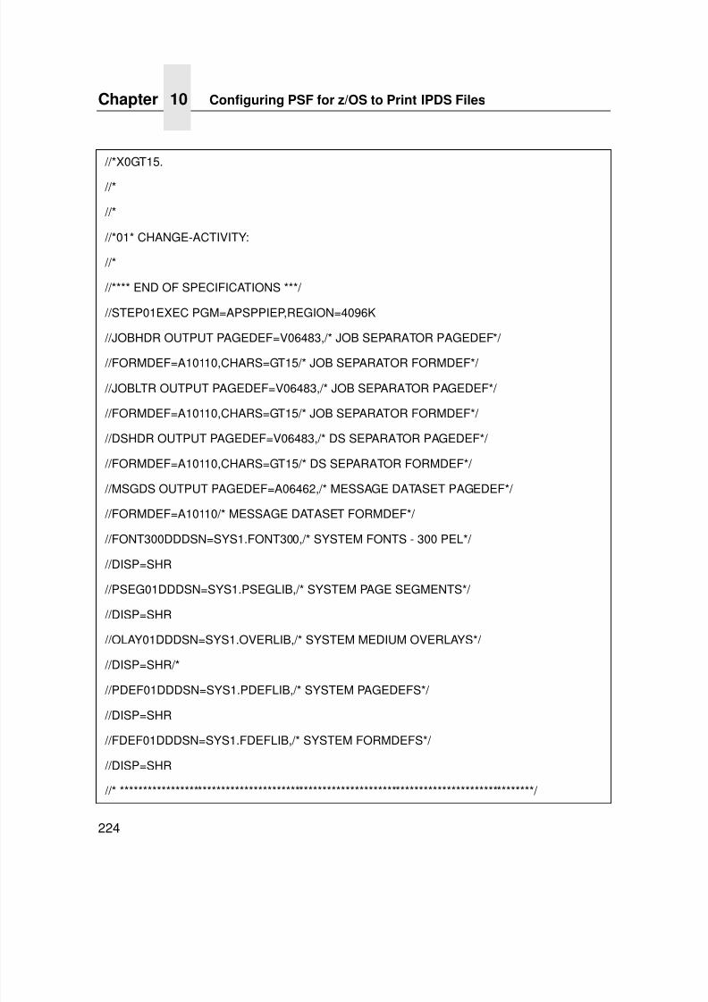
7/23/2019 54458302 IBM 6400
http://slidepdf.com/reader/full/54458302-ibm-6400 226/349
Chapter 10 Configuring PSF for z/OS to Print IPDS Files
224
//*X0GT15.
//*
//*
//*01* CHANGE-ACTIVITY:
//*
//**** END OF SPECIFICATIONS ***/
//STEP01EXEC PGM=APSPPIEP,REGION=4096K
//JOBHDR OUTPUT PAGEDEF=V06483,/* JOB SEPARATOR PAGEDEF*/
//FORMDEF=A10110,CHARS=GT15/* JOB SEPARATOR FORMDEF*/
//JOBLTR OUTPUT PAGEDEF=V06483,/* JOB SEPARATOR PAGEDEF*/
//FORMDEF=A10110,CHARS=GT15/* JOB SEPARATOR FORMDEF*/
//DSHDR OUTPUT PAGEDEF=V06483,/* DS SEPARATOR PAGEDEF*/
//FORMDEF=A10110,CHARS=GT15/* DS SEPARATOR FORMDEF*/
//MSGDS OUTPUT PAGEDEF=A06462,/* MESSAGE DATASET PAGEDEF*/
//FORMDEF=A10110/* MESSAGE DATASET FORMDEF*/
//FONT300DDDSN=SYS1.FONT300,/* SYSTEM FONTS - 300 PEL*/
//DISP=SHR
//PSEG01DDDSN=SYS1.PSEGLIB,/* SYSTEM PAGE SEGMENTS*/
//DISP=SHR
//OLAY01DDDSN=SYS1.OVERLIB,/* SYSTEM MEDIUM OVERLAYS*/
//DISP=SHR/*
//PDEF01DDDSN=SYS1.PDEFLIB,/* SYSTEM PAGEDEFS*/
//DISP=SHR
//FDEF01DDDSN=SYS1.FDEFLIB,/* SYSTEM FORMDEFS*/
//DISP=SHR
//* ******************************************************************************************/
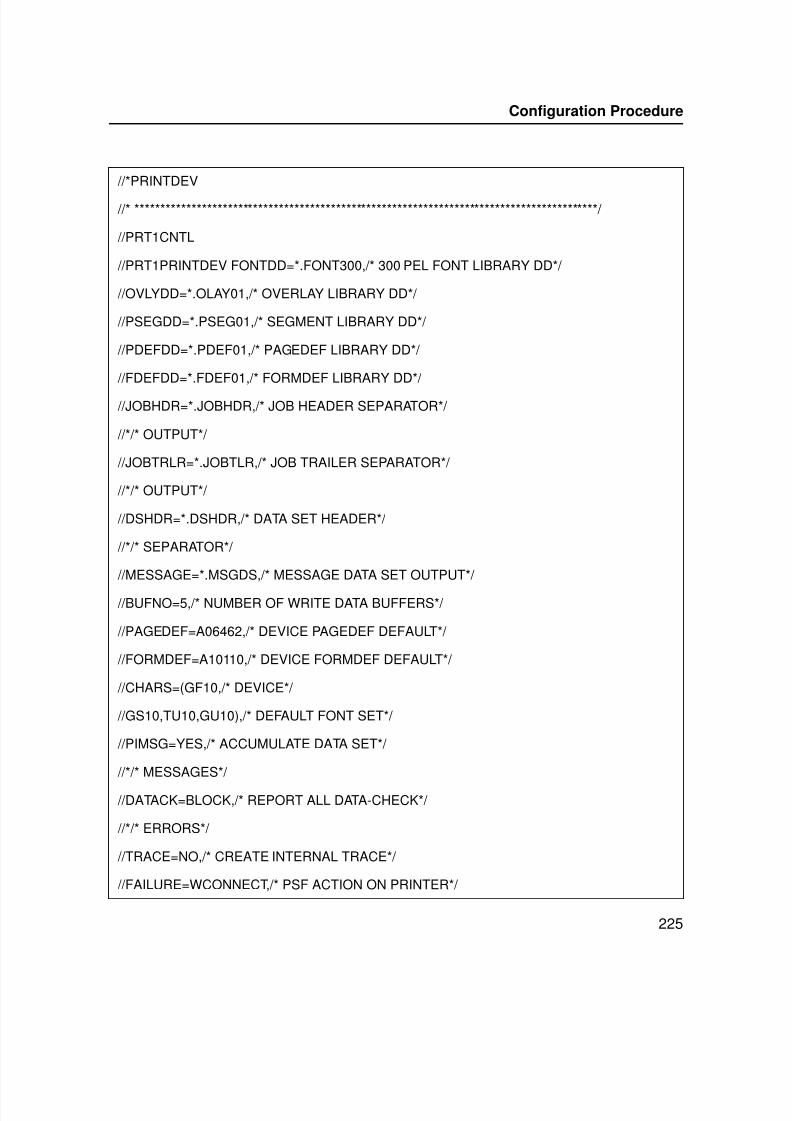
7/23/2019 54458302 IBM 6400
http://slidepdf.com/reader/full/54458302-ibm-6400 227/349
Configuration Procedure
225
//*PRINTDEV
//* ******************************************************************************************/
//PRT1CNTL
//PRT1PRINTDEV FONTDD=*.FONT300,/* 300 PEL FONT LIBRARY DD*/
//OVLYDD=*.OLAY01,/* OVERLAY LIBRARY DD*/
//PSEGDD=*.PSEG01,/* SEGMENT LIBRARY DD*/
//PDEFDD=*.PDEF01,/* PAGEDEF LIBRARY DD*/
//FDEFDD=*.FDEF01,/* FORMDEF LIBRARY DD*/
//JOBHDR=*.JOBHDR,/* JOB HEADER SEPARATOR*/
//*/* OUTPUT*/
//JOBTRLR=*.JOBTLR,/* JOB TRAILER SEPARATOR*/
//*/* OUTPUT*/
//DSHDR=*.DSHDR,/* DATA SET HEADER*/
//*/* SEPARATOR*/
//MESSAGE=*.MSGDS,/* MESSAGE DATA SET OUTPUT*/
//BUFNO=5,/* NUMBER OF WRITE DATA BUFFERS*/
//PAGEDEF=A06462,/* DEVICE PAGEDEF DEFAULT*/
//FORMDEF=A10110,/* DEVICE FORMDEF DEFAULT*/
//CHARS=(GF10,/* DEVICE*/
//GS10,TU10,GU10),/* DEFAULT FONT SET*/
//PIMSG=YES,/* ACCUMULATE DATA SET*/
//*/* MESSAGES*/
//DATACK=BLOCK,/* REPORT ALL DATA-CHECK*/
//*/* ERRORS*/
//TRACE=NO,/* CREATE INTERNAL TRACE*/
//FAILURE=WCONNECT,/* PSF ACTION ON PRINTER*/
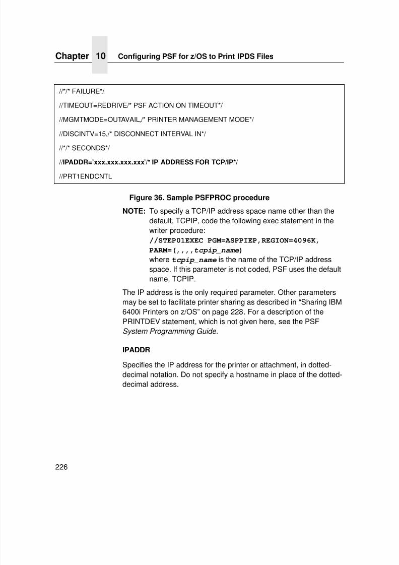
7/23/2019 54458302 IBM 6400
http://slidepdf.com/reader/full/54458302-ibm-6400 228/349
Chapter 10 Configuring PSF for z/OS to Print IPDS Files
226
Figure 36. Sample PSFPROC procedure
NOTE: To specify a TCP/IP address space name other than thedefault, TCPIP, code the following exec statement in thewriter procedure://STEP01EXEC PGM=ASPPIEP,REGION=4096K,
PARM=(,,,,tcpip_name)
where tcpip_name is the name of the TCP/IP addressspace. If this parameter is not coded, PSF uses the defaultname, TCPIP.
The IP address is the only required parameter. Other parametersmay be set to facilitate printer sharing as described in “Sharing IBM6400i Printers on z/OS” on page 228. For a description of thePRINTDEV statement, which is not given here, see the PSFSystem Programming Guide .
IPADDR
Specifies the IP address for the printer or attachment, in dotted-decimal notation. Do not specify a hostname in place of the dotted-decimal address.
//*/* FAILURE*/
//TIMEOUT=REDRIVE/* PSF ACTION ON TIMEOUT*/
//MGMTMODE=OUTAVAIL,/* PRINTER MANAGEMENT MODE*/
//DISCINTV=15,/* DISCONNECT INTERVAL IN*/
//*/* SECONDS*/
// IPADDR=’xxx.xxx.xxx.xxx’/* IP ADDRESS FOR TCP/IP*/
//PRT1ENDCNTL
7/23/2019 54458302 IBM 6400
http://slidepdf.com/reader/full/54458302-ibm-6400 229/349
Verifying a TCP/IP-Attached Printer on z/OS
227
Verifying a TCP/IP-Attached Printer on z/OS
To operate a TCP/IP-attached printer, use JES operatorcommands.
Starting a TCP/IP-attached Printer
To start a TCP/IP-attached printer, do the following:
1. Start TCP/IP.
2. Power on the printer.
3. Start the printer FSA.
• On JES2, the command is:$S printer_name
• On JES3, the command is:*VARY printer_name,ON
Stopping a TCP/IP-attached Printer
You can stop a TCP/IP-attached printer in several ways:
• The preferred method is to first stop the PSF FSA for the printer
by entering the following command from the z/OS console:
JES2:$P printer_name
JES3:*VARY printer_name,OFF
*CANCEL printer_name
where printer_name specifies the name of the printer FSA.
Then you can turn off power to the printer.
• To end the PSF FSA for the printer, use the JES commands. Ifyou are unable to purge or cancel the printer by use of the JEScommands, enter the following command:
MODIFY FSSname,FORCE, printer_name
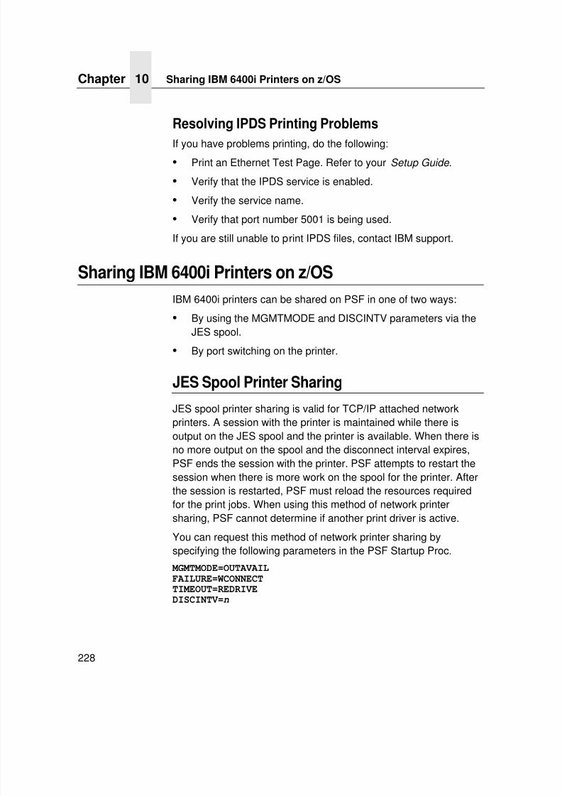
7/23/2019 54458302 IBM 6400
http://slidepdf.com/reader/full/54458302-ibm-6400 230/349
Chapter 10 Sharing IBM 6400i Printers on z/OS
228
Resolving IPDS Printing Problems
If you have problems printing, do the following:
• Print an Ethernet Test Page. Refer to your Setup Guide .
• Verify that the IPDS service is enabled.
• Verify the service name.
• Verify that port number 5001 is being used.
If you are still unable to print IPDS files, contact IBM support.
Sharing IBM 6400i Printers on z/OSIBM 6400i printers can be shared on PSF in one of two ways:
• By using the MGMTMODE and DISCINTV parameters via theJES spool.
• By port switching on the printer.
JES Spool Printer Sharing
JES spool printer sharing is valid for TCP/IP attached networkprinters. A session with the printer is maintained while there isoutput on the JES spool and the printer is available. When there isno more output on the spool and the disconnect interval expires,PSF ends the session with the printer. PSF attempts to restart thesession when there is more work on the spool for the printer. Afterthe session is restarted, PSF must reload the resources requiredfor the print jobs. When using this method of network printersharing, PSF cannot determine if another print driver is active.
You can request this method of network printer sharing by
specifying the following parameters in the PSF Startup Proc. MGMTMODE=OUTAVAILFAILURE=WCONNECTTIMEOUT=REDRIVEDISCINTV=n
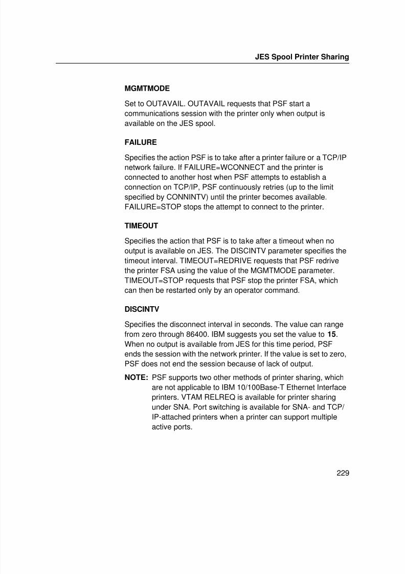
7/23/2019 54458302 IBM 6400
http://slidepdf.com/reader/full/54458302-ibm-6400 231/349
JES Spool Printer Sharing
229
MGMTMODE
Set to OUTAVAIL. OUTAVAIL requests that PSF start acommunications session with the printer only when output isavailable on the JES spool.
FAILURE
Specifies the action PSF is to take after a printer failure or a TCP/IPnetwork failure. If FAILURE=WCONNECT and the printer isconnected to another host when PSF attempts to establish aconnection on TCP/IP, PSF continuously retries (up to the limit
specified by CONNINTV) until the printer becomes available.FAILURE=STOP stops the attempt to connect to the printer.
TIMEOUT
Specifies the action that PSF is to take after a timeout when nooutput is available on JES. The DISCINTV parameter specifies thetimeout interval. TIMEOUT=REDRIVE requests that PSF redrivethe printer FSA using the value of the MGMTMODE parameter.TIMEOUT=STOP requests that PSF stop the printer FSA, whichcan then be restarted only by an operator command.
DISCINTV
Specifies the disconnect interval in seconds. The value can rangefrom zero through 86400. IBM suggests you set the value to 15.When no output is available from JES for this time period, PSFends the session with the network printer. If the value is set to zero,PSF does not end the session because of lack of output.
NOTE: PSF supports two other methods of printer sharing, whichare not applicable to IBM 10/100Base-T Ethernet Interface
printers. VTAM RELREQ is available for printer sharingunder SNA. Port switching is available for SNA- and TCP/ IP-attached printers when a printer can support multipleactive ports.
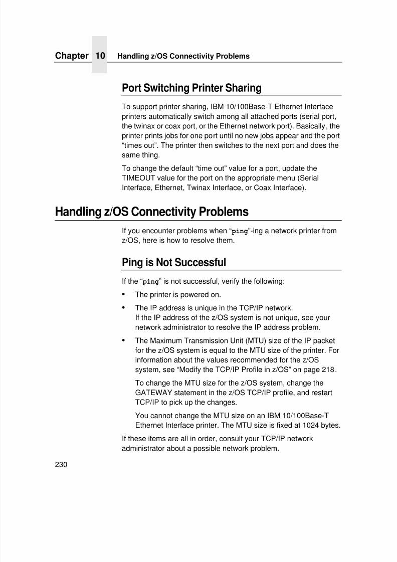
7/23/2019 54458302 IBM 6400
http://slidepdf.com/reader/full/54458302-ibm-6400 232/349
Chapter 10 Handling z/OS Connectivity Problems
230
Port Switching Printer Sharing
To support printer sharing, IBM 10/100Base-T Ethernet Interfaceprinters automatically switch among all attached ports (serial port,the twinax or coax port, or the Ethernet network port). Basically, theprinter prints jobs for one port until no new jobs appear and the port“times out”. The printer then switches to the next port and does thesame thing.
To change the default “time out” value for a port, update theTIMEOUT value for the port on the appropriate menu (SerialInterface, Ethernet, Twinax Interface, or Coax Interface).
Handling z/OS Connectivity Problems
If you encounter problems when “ ping”-ing a network printer fromz/OS, here is how to resolve them.
Ping is Not Successful
If the “ ping” is not successful, verify the following:
• The printer is powered on.• The IP address is unique in the TCP/IP network.
If the IP address of the z/OS system is not unique, see yournetwork administrator to resolve the IP address problem.
• The Maximum Transmission Unit (MTU) size of the IP packetfor the z/OS system is equal to the MTU size of the printer. Forinformation about the values recommended for the z/OSsystem, see “Modify the TCP/IP Profile in z/OS” on page 218.
To change the MTU size for the z/OS system, change the
GATEWAY statement in the z/OS TCP/IP profile, and restartTCP/IP to pick up the changes.
You cannot change the MTU size on an IBM 10/100Base-TEthernet Interface printer. The MTU size is fixed at 1024 bytes.
If these items are all in order, consult your TCP/IP networkadministrator about a possible network problem.
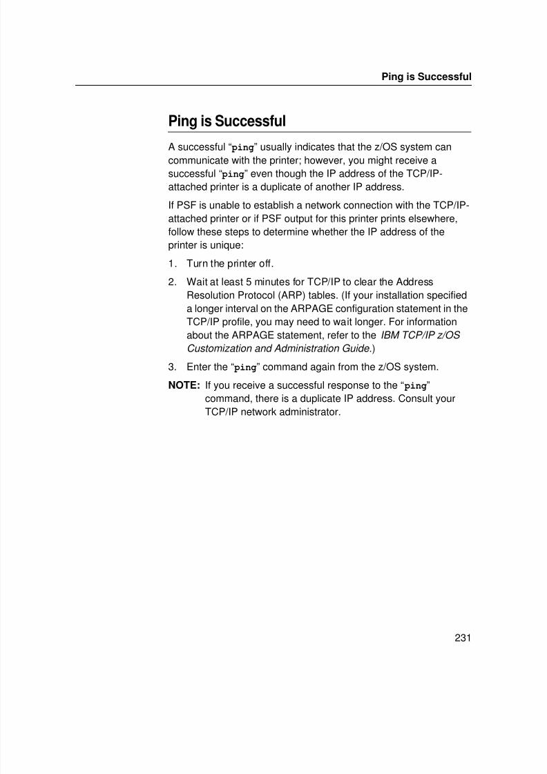
7/23/2019 54458302 IBM 6400
http://slidepdf.com/reader/full/54458302-ibm-6400 233/349
Ping is Successful
231
Ping is Successful
A successful “ ping” usually indicates that the z/OS system cancommunicate with the printer; however, you might receive asuccessful “ ping” even though the IP address of the TCP/IP-attached printer is a duplicate of another IP address.
If PSF is unable to establish a network connection with the TCP/IP-attached printer or if PSF output for this printer prints elsewhere,follow these steps to determine whether the IP address of theprinter is unique:
1. Turn the printer off.
2. Wait at least 5 minutes for TCP/IP to clear the AddressResolution Protocol (ARP) tables. (If your installation specifieda longer interval on the ARPAGE configuration statement in theTCP/IP profile, you may need to wait longer. For informationabout the ARPAGE statement, refer to the IBM TCP/IP z/OS
Customization and Administration Guide .)
3. Enter the “ ping” command again from the z/OS system.
NOTE: If you receive a successful response to the “ ping”command, there is a duplicate IP address. Consult yourTCP/IP network administrator.

7/23/2019 54458302 IBM 6400
http://slidepdf.com/reader/full/54458302-ibm-6400 234/349
Chapter 10 Handling z/OS Connectivity Problems
232
7/23/2019 54458302 IBM 6400
http://slidepdf.com/reader/full/54458302-ibm-6400 235/349
233
11 z/OS Configuration,TN3270E
z/OS Configuration For A TN3270E PrinterThe following configuration information shows how a 6400i printercan be configured on z/OS and Info Print Server to print TN3270E.Modtabs are provided for both an SCS and DSC printer. The z/OSlevel is 1.3.
These basic configurations provided a starting point for users newto printing in this manner.
NOTE: Since Info Print Server (IPS) treats the TN3270E printer asa COAX attached printer, additional COAX feature for IPSis required.
Coax Printer Support FMID
Coax Printer Support consists of the following FMID:
HPRT100
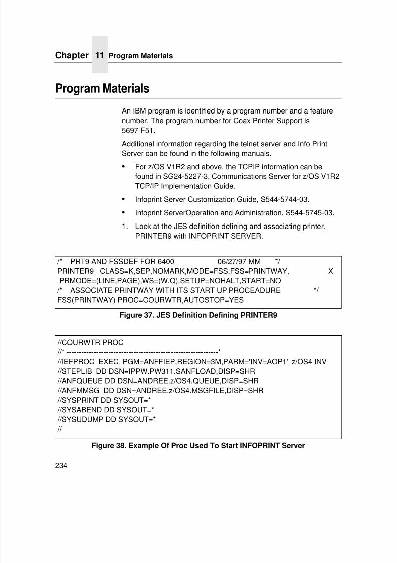
7/23/2019 54458302 IBM 6400
http://slidepdf.com/reader/full/54458302-ibm-6400 236/349
Chapter 11 Program Materials
234
Program Materials
An IBM program is identified by a program number and a featurenumber. The program number for Coax Printer Support is5697-F51.
Additional information regarding the telnet server and Info PrintServer can be found in the following manuals.
• For z/OS V1R2 and above, the TCPIP information can befound in SG24-5227-3, Communications Server for z/OS V1R2TCP/IP Implementation Guide.
• Infoprint Server Customization Guide, S544-5744-03.
• Infoprint ServerOperation and Administration, S544-5745-03.
1. Look at the JES definition defining and associating printer,PRINTER9 with INFOPRINT SERVER.
Figure 37. JES Definition Defining PRINTER9
Figure 38. Example Of Proc Used To Start INFOPRINT Server
/* PRT9 AND FSSDEF FOR 6400 06/27/97 MM */ PRINTER9 CLASS=K,SEP,NOMARK,MODE=FSS,FSS=PRINTWAY, XPRMODE=(LINE,PAGE),WS=(W,Q),SETUP=NOHALT,START=NO
/* ASSOCIATE PRINTWAY WITH ITS START UP PROCEADURE */ FSS(PRINTWAY) PROC=COURWTR,AUTOSTOP=YES
//COURWTR PROC //* -------------------------------------------------------------* //IEFPROC EXEC PGM=ANFFIEP,REGION=3M,PARM='INV=AOP1' z/OS4 INV //STEPLIB DD DSN=IPPW.PW311.SANFLOAD,DISP=SHR //ANFQUEUE DD DSN=ANDREE.z/OS4.QUEUE,DISP=SHR
//ANFMMSG DD DSN=ANDREE.z/OS4.MSGFILE,DISP=SHR //SYSPRINT DD SYSOUT=* //SYSABEND DD SYSOUT=* //SYSUDUMP DD SYSOUT=* //
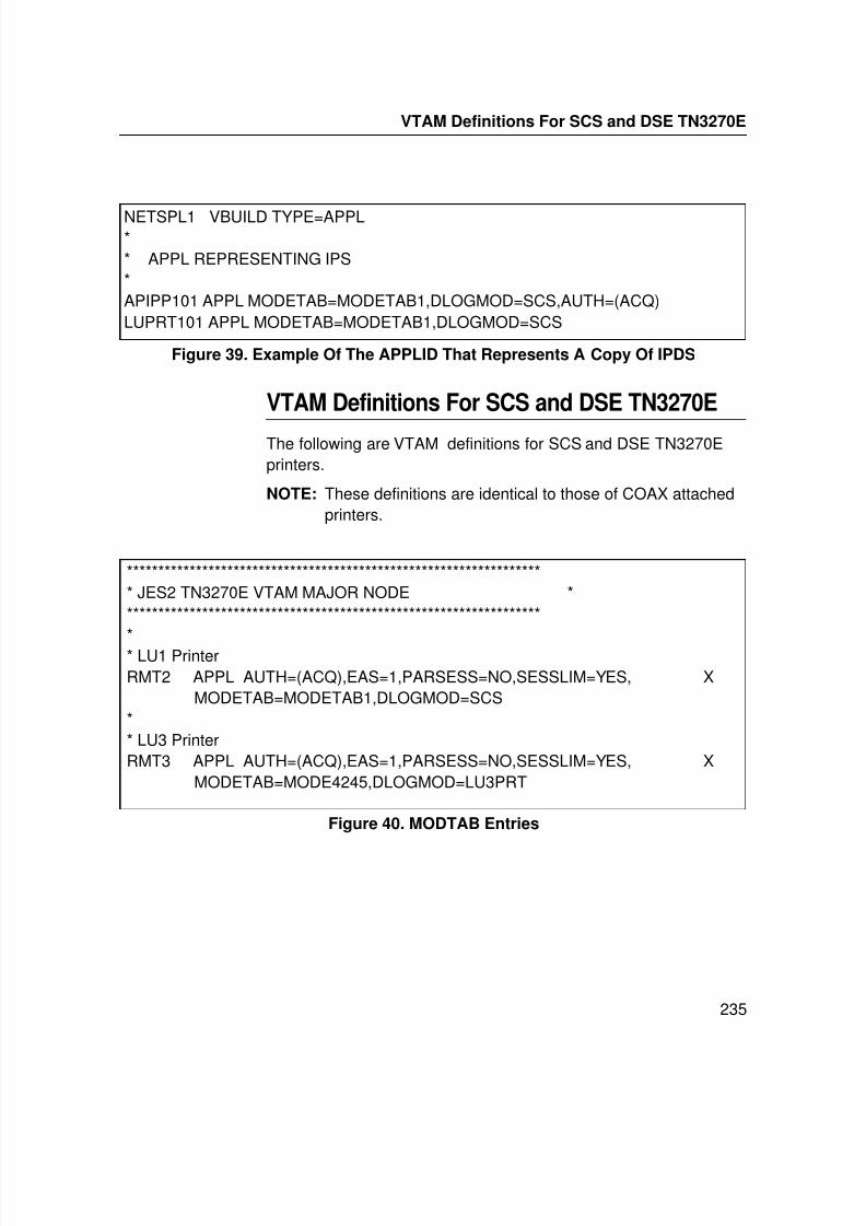
7/23/2019 54458302 IBM 6400
http://slidepdf.com/reader/full/54458302-ibm-6400 237/349
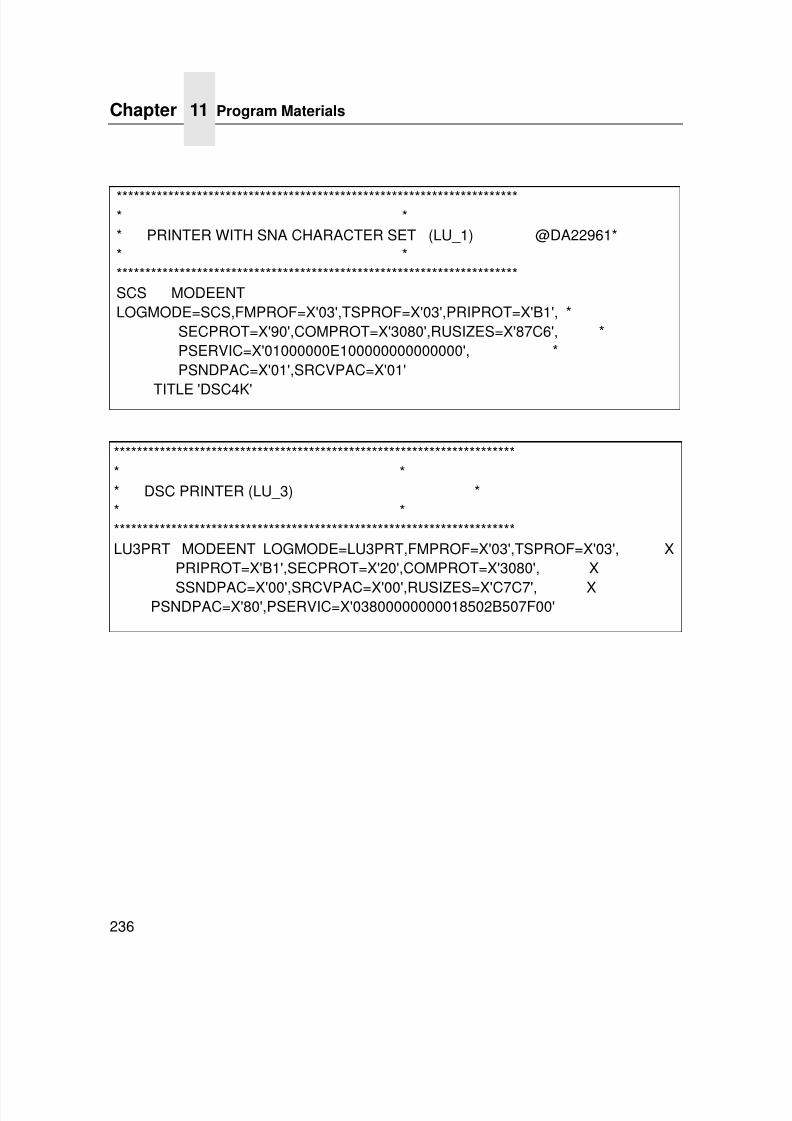
7/23/2019 54458302 IBM 6400
http://slidepdf.com/reader/full/54458302-ibm-6400 238/349
Chapter 11 Program Materials
236
*********************************************************************** ** PRINTER WITH SNA CHARACTER SET (LU_1) @DA22961** ***********************************************************************SCS MODEENTLOGMODE=SCS,FMPROF=X'03',TSPROF=X'03',PRIPROT=X'B1', *
SECPROT=X'90',COMPROT=X'3080',RUSIZES=X'87C6', *PSERVIC=X'01000000E100000000000000', *PSNDPAC=X'01',SRCVPAC=X'01'
TITLE 'DSC4K'
*********************************************************************** ** DSC PRINTER (LU_3) ** ***********************************************************************LU3PRT MODEENT LOGMODE=LU3PRT,FMPROF=X'03',TSPROF=X'03', X
PRIPROT=X'B1',SECPROT=X'20',COMPROT=X'3080', X
SSNDPAC=X'00',SRCVPAC=X'00',RUSIZES=X'C7C7', XPSNDPAC=X'80',PSERVIC=X'03800000000018502B507F00'
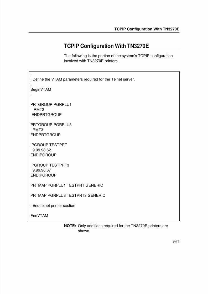
7/23/2019 54458302 IBM 6400
http://slidepdf.com/reader/full/54458302-ibm-6400 239/349
TCPIP Configuration With TN3270E
237
TCPIP Configuration With TN3270E
The following is the portion of the system’s TCPIP configurationinvolved with TN3270E printers.
NOTE: Only additions required for the TN3270E printers areshown.
;; Define the VTAM parameters required for the Telnet server.;BeginVTAM;
PRTGROUP PGRPLU1RMT2
ENDPRTGROUP
PRTGROUP PGRPLU3RMT3
ENDPRTGROUP
IPGROUP TESTPRT9.99.98.62
ENDIPGROUP
IPGROUP TESTPRT39.99.98.67
ENDIPGROUP
PRTMAP PGRPLU1 TESTPRT GENERIC
PRTMAP PGRPLU3 TESTPRT3 GENERIC
; End telnet printer section
EndVTAM
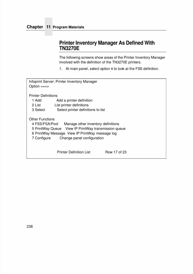
7/23/2019 54458302 IBM 6400
http://slidepdf.com/reader/full/54458302-ibm-6400 240/349
Chapter 11 Program Materials
238
Printer Inventory Manager As Defined With
TN3270E
The following screens show areas of the Printer Inventory Managerinvolved with the definition of the TN3270E printers.
1. At main panel, select option 4 to look at the FSS definition.
Infoprint Server: Printer Inventory ManagerOption ===>
Printer Definitions1 Add Add a printer definition2 List List printer definitions3 Select Select printer definitions to list
Other Functions4 FSS/FSA/Pool Manage other inventory definitions5 PrintWay Queue View IP PrintWay transmission queue6 PrintWay Message View IP PrintWay message log7 Configure Change panel configuration
Printer Definition List Row 17 of 23
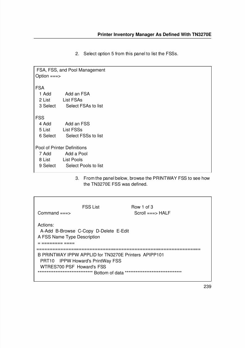
7/23/2019 54458302 IBM 6400
http://slidepdf.com/reader/full/54458302-ibm-6400 241/349
Printer Inventory Manager As Defined With TN3270E
239
2. Select option 5 from this panel to list the FSSs.
3. From the panel below, browse the PRINTWAY FSS to see how
the TN3270E FSS was defined.
FSA, FSS, and Pool ManagementOption ===>
FSA1 Add Add an FSA2 List List FSAs3 Select Select FSAs to list
FSS4 Add Add an FSS5 List List FSSs6 Select Select FSSs to list
Pool of Printer Definitions7 Add Add a Pool8 List List Pools9 Select Select Pools to list
FSS List Row 1 of 3Command ===> Scroll ===> HALF
Actions:A-Add B-Browse C-Copy D-Delete E-Edit
A FSS Name Type Description
= ======== ==================================================================B PRINTWAY IPPW APPLID for TN3270E Printers APIPP101PRT10 IPPW Howard's PrintWay FSSWTRES700 PSF Howard's FSS
******************************* Bottom of data ********************************
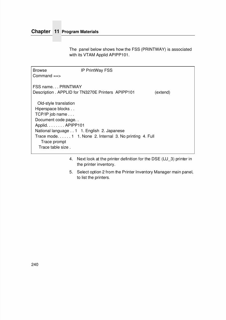
7/23/2019 54458302 IBM 6400
http://slidepdf.com/reader/full/54458302-ibm-6400 242/349
Chapter 11 Program Materials
240
The panel below shows how the FSS (PRINTWAY) is associated
with its VTAM Applid APIPP101.
4. Next look at the printer definition for the DSE (LU_3) printer inthe printer inventory.
5. Select option 2 from the Printer Inventory Manager main panel,to list the printers.
Browse IP PrintWay FSSCommand ==>
FSS name. . . PRINTWAYDescription . APPLID for TN3270E Printers APIPP101 (extend)
Old-style translationHiperspace blocks . .TCP/IP job name . . .Document code page. .Applid. . . . . . . . APIPP101National language . . 1 1. English 2. JapaneseTrace mode. . . . . . 1 1. None 2. Internal 3. No printing 4. Full
Trace promptTrace table size .
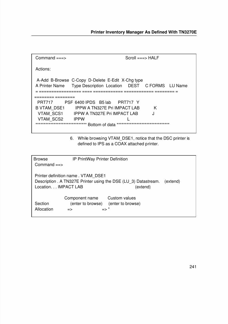
7/23/2019 54458302 IBM 6400
http://slidepdf.com/reader/full/54458302-ibm-6400 243/349
Printer Inventory Manager As Defined With TN3270E
241
6. While browsing VTAM_DSE1, notice that the DSC printer isdefined to IPS as a COAX attached printer.
Command ===> Scroll ===> HALF
Actions:
A-Add B-Browse C-Copy D-Delete E-Edit X-Chg typeA Printer Name Type Description Location DEST C FORMS LU Name= ================= ==== ============ ============ ======== =
======== ========PRT717 PSF 6400 IPDS B5 lab PRT717 Y
B VTAM_DSE1 IPPW A TN327E Pri IMPACT LAB K
VTAM_SCS1 IPPW A TN327E Pri IMPACT LAB JVTAM_SCS2 IPPW L
******************************* Bottom of data ********************************
Browse IP PrintWay Printer DefinitionCommand ==>
Printer definition name . VTAM_DSE1Description . A TN327E Printer using the DSE (LU_3) Datastream. (extend)Location. . . IMPACT LAB (extend)
Component name Custom valuesSection (enter to browse) (enter to browse)Allocation => => *
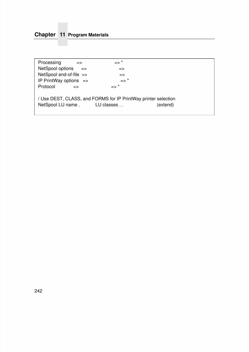
7/23/2019 54458302 IBM 6400
http://slidepdf.com/reader/full/54458302-ibm-6400 244/349
Chapter 11 Program Materials
242
Processing => => *NetSpool options => =>NetSpool end-of-file => =>IP PrintWay options => => *Protocol => => *
/ Use DEST, CLASS, and FORMS for IP PrintWay printer selectionNetSpool LU name . LU classes . . (extend)
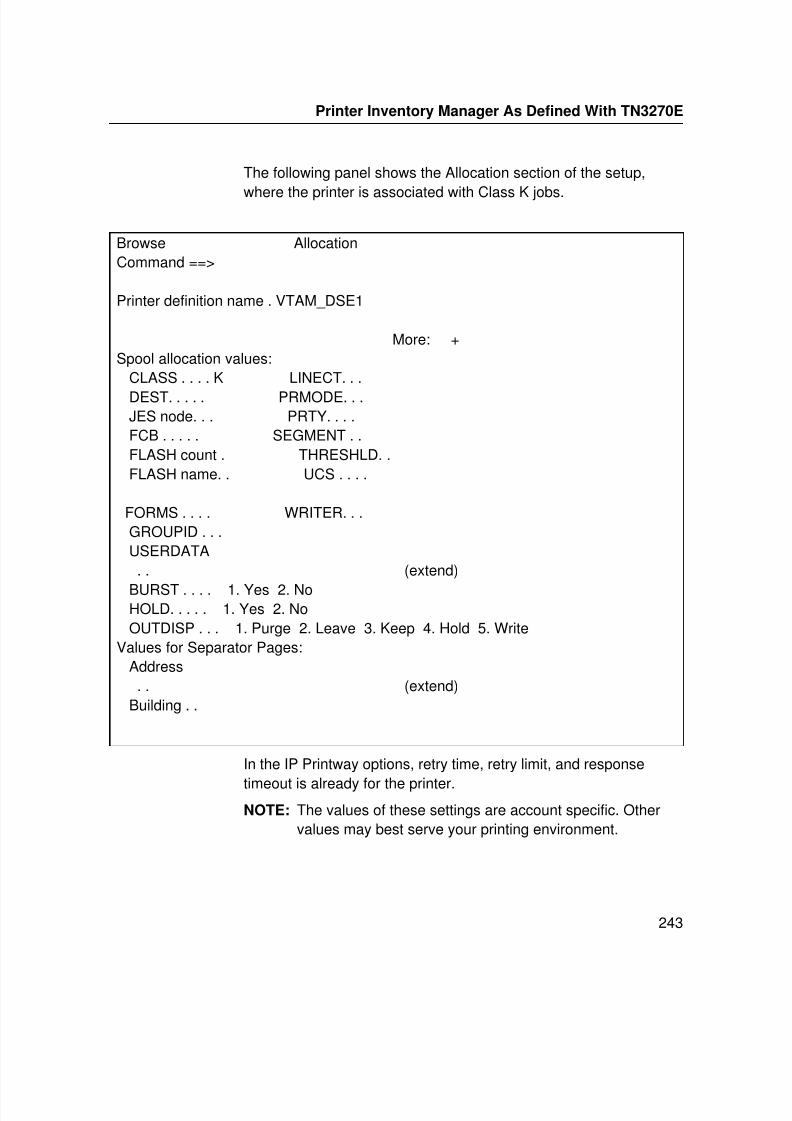
7/23/2019 54458302 IBM 6400
http://slidepdf.com/reader/full/54458302-ibm-6400 245/349
Printer Inventory Manager As Defined With TN3270E
243
The following panel shows the Allocation section of the setup,
where the printer is associated with Class K jobs.
In the IP Printway options, retry time, retry limit, and response
timeout is already for the printer.NOTE: The values of these settings are account specific. Other
values may best serve your printing environment.
Browse AllocationCommand ==>
Printer definition name . VTAM_DSE1
More: +Spool allocation values:
CLASS . . . . K LINECT. . .
DEST. . . . . PRMODE. . .JES node. . . PRTY. . . .FCB . . . . . SEGMENT . .FLASH count . THRESHLD. .FLASH name. . UCS . . . .
FORMS . . . . WRITER. . .GROUPID . . .USERDATA. . (extend)
BURST . . . . 1. Yes 2. NoHOLD. . . . . 1. Yes 2. NoOUTDISP . . . 1. Purge 2. Leave 3. Keep 4. Hold 5. Write
Values for Separator Pages:Address. . (extend)
Building . .
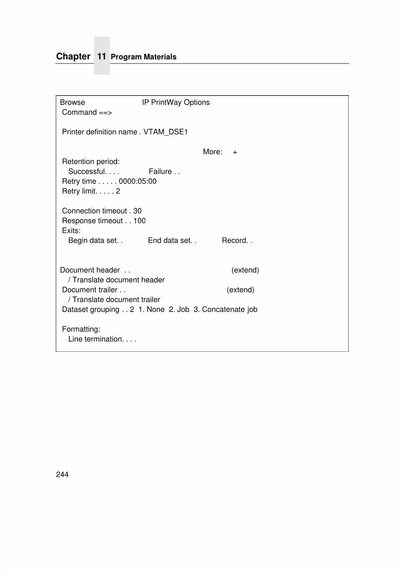
7/23/2019 54458302 IBM 6400
http://slidepdf.com/reader/full/54458302-ibm-6400 246/349
Chapter 11 Program Materials
244
Browse IP PrintWay OptionsCommand ==>
Printer definition name . VTAM_DSE1
More: +Retention period:
Successful. . . . Failure . .Retry time . . . . . 0000:05:00Retry limit. . . . . 2
Connection timeout . 30Response timeout . . 100Exits:
Begin data set. . End data set. . Record. .
Document header . . (extend) / Translate document header
Document trailer . . (extend)
/ Translate document trailerDataset grouping . . 2 1. None 2. Job 3. Concatenate job
Formatting:Line termination. . . .
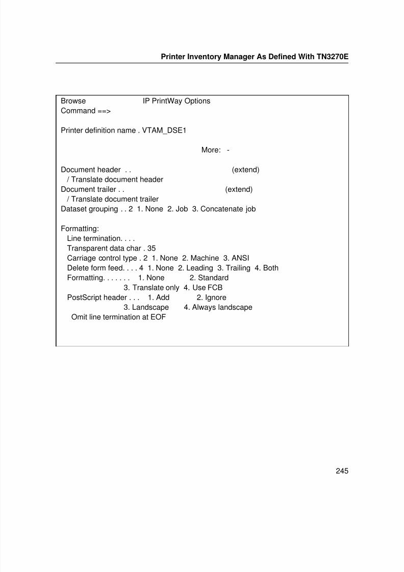
7/23/2019 54458302 IBM 6400
http://slidepdf.com/reader/full/54458302-ibm-6400 247/349
Printer Inventory Manager As Defined With TN3270E
245
Browse IP PrintWay OptionsCommand ==>
Printer definition name . VTAM_DSE1
More: -
Document header . . (extend) / Translate document header
Document trailer . . (extend)
/ Translate document trailerDataset grouping . . 2 1. None 2. Job 3. Concatenate job
Formatting:Line termination. . . .Transparent data char . 35Carriage control type . 2 1. None 2. Machine 3. ANSIDelete form feed. . . . 4 1. None 2. Leading 3. Trailing 4. BothFormatting. . . . . . . 1. None 2. Standard
3. Translate only 4. Use FCB
PostScript header . . . 1. Add 2. Ignore3. Landscape 4. Always landscapeOmit line termination at EOF
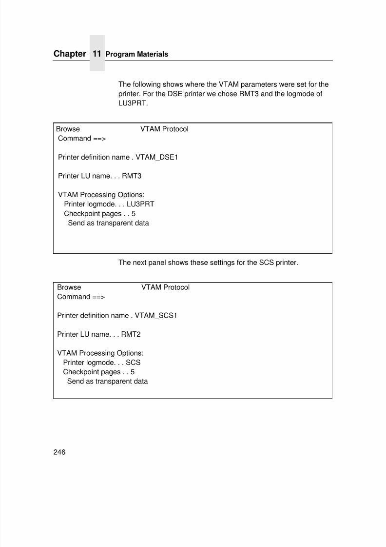
7/23/2019 54458302 IBM 6400
http://slidepdf.com/reader/full/54458302-ibm-6400 248/349
Chapter 11 Program Materials
246
The following shows where the VTAM parameters were set for the
printer. For the DSE printer we chose RMT3 and the logmode ofLU3PRT.
The next panel shows these settings for the SCS printer.
Browse VTAM ProtocolCommand ==>
Printer definition name . VTAM_DSE1
Printer LU name. . . RMT3
VTAM Processing Options:Printer logmode. . . LU3PRTCheckpoint pages . . 5Send as transparent data
Browse VTAM ProtocolCommand ==>
Printer definition name . VTAM_SCS1
Printer LU name. . . RMT2
VTAM Processing Options:Printer logmode. . . SCSCheckpoint pages . . 5
Send as transparent data
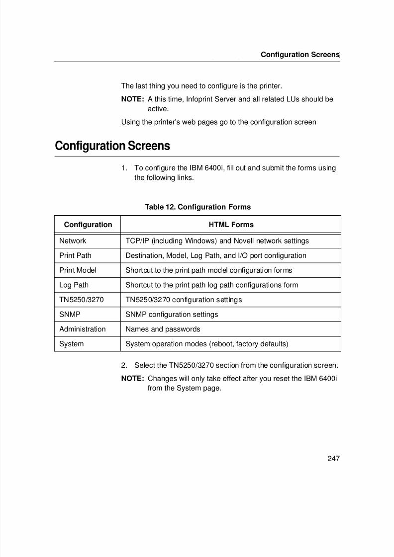
7/23/2019 54458302 IBM 6400
http://slidepdf.com/reader/full/54458302-ibm-6400 249/349
Printer Inventory Manager As Defined With TN3270E
247
The last thing you need to configure is the printer.
NOTE: A this time, Infoprint Server and all related LUs should beactive.
Using the printer's web pages go to the configuration screen
Configuration Screens
1. To configure the IBM 6400i, fill out and submit the forms usingthe following links.
2. Select the TN5250/3270 section from the configuration screen.
NOTE: Changes will only take effect after you reset the IBM 6400i
from the System page.
Table 12. Configuration Forms
Configuration HTML Forms
Network TCP/IP (including Windows) and Novell network settings
Print Path Destination, Model, Log Path, and I/O port configuration
Print Model Shortcut to the print path model configuration forms
Log Path Shortcut to the print path log path configurations form
TN5250/3270 TN5250/3270 configuration settings
SNMP SNMP configuration settings
Administration Names and passwords
System System operation modes (reboot, factory defaults)
Configuration Screens
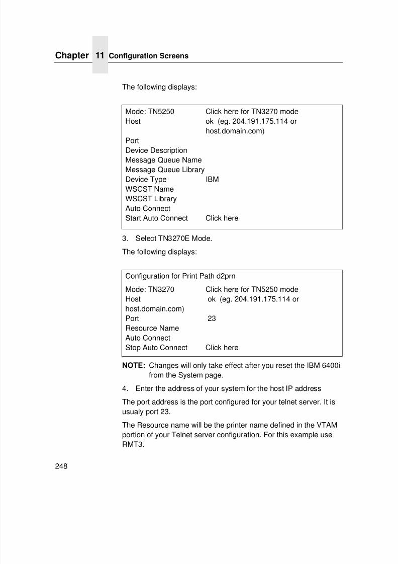
7/23/2019 54458302 IBM 6400
http://slidepdf.com/reader/full/54458302-ibm-6400 250/349
Chapter 11 Configuration Screens
248
The following displays:
3. Select TN3270E Mode.
The following displays:
NOTE: Changes will only take effect after you reset the IBM 6400ifrom the System page.
4. Enter the address of your system for the host IP address
The port address is the port configured for your telnet server. It isusualy port 23.
The Resource name will be the printer name defined in the VTAMportion of your Telnet server configuration. For this example useRMT3.
Mode: TN5250 Click here for TN3270 modeHost ok (eg. 204.191.175.114 or
host.domain.com)PortDevice DescriptionMessage Queue NameMessage Queue LibraryDevice Type IBMWSCST Name
WSCST LibraryAuto ConnectStart Auto Connect Click here
Configuration for Print Path d2prn
Mode: TN3270 Click here for TN5250 modeHost ok (eg. 204.191.175.114 orhost.domain.com)Port 23Resource NameAuto ConnectStop Auto Connect Click here
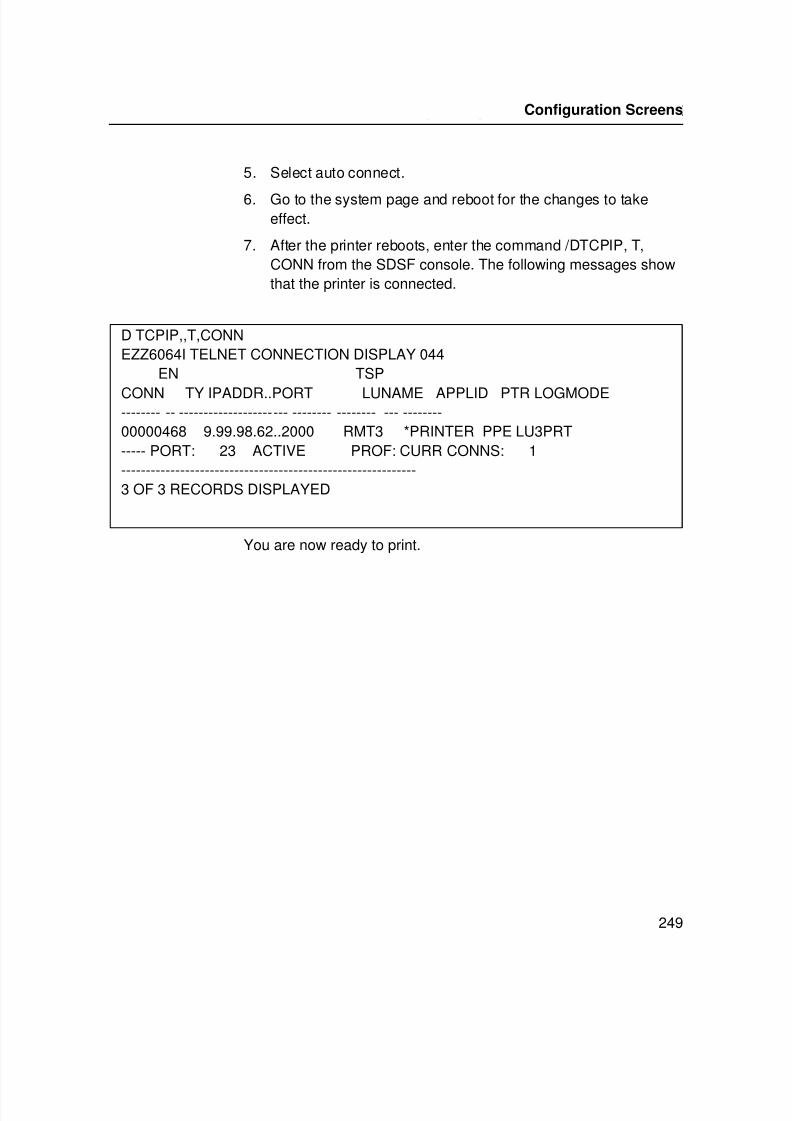
7/23/2019 54458302 IBM 6400
http://slidepdf.com/reader/full/54458302-ibm-6400 251/349
Printer Inventory Manager As Defined With TN3270E
249
5. Select auto connect.
6. Go to the system page and reboot for the changes to takeeffect.
7. After the printer reboots, enter the command /DTCPIP, T,CONN from the SDSF console. The following messages showthat the printer is connected.
You are now ready to print.
D TCPIP,,T,CONNEZZ6064I TELNET CONNECTION DISPLAY 044
EN TSP
CONN TY IPADDR..PORT LUNAME APPLID PTR LOGMODE-------- -- ---------------------- -------- -------- --- --------00000468 9.99.98.62..2000 RMT3 *PRINTER PPE LU3PRT----- PORT: 23 ACTIVE PROF: CURR CONNS: 1------------------------------------------------------------3 OF 3 RECORDS DISPLAYED
Configuration Screens

7/23/2019 54458302 IBM 6400
http://slidepdf.com/reader/full/54458302-ibm-6400 252/349
Chapter 11 Configuration Screens
250
7/23/2019 54458302 IBM 6400
http://slidepdf.com/reader/full/54458302-ibm-6400 253/349
251
12 iSeries Configuration,TN5250
Setting Up TN5250 Print Queues on iSeriesStart with V3R7 or later and the most recent PTF level. The iSeriesshould have tcpip installed, be fully configured, and functional. Toset up the TN5250 print queues, do the following:
1. Make sure the iSeries has sufficient resources to add additionalvirtual devices.
2. Establish the IP value (not the dns name) of the iSeries.
3. Set the IP, subnet mask, and default router on the Ethernet
adapter.4. Use a telnet session or web browser session to configure three
items per dest (logical Ethernet queue) for use as a logicalnetwork connection to the iSeries.
NOTE: The three values (i.e., 192.168.168.34) represent theiSeries IP in dotted notation and are the entries for theiSeries.
The newly created TN5250 device/queue (i.e. pallet form, firstchair is alpha, 10 char. max) assumes the new name
“devicedesc.”5. Determine whether or not to autoconnect (initiate connection
on power up or through Ethernet reset) the TN5250 device/ queue.
7/23/2019 54458302 IBM 6400
http://slidepdf.com/reader/full/54458302-ibm-6400 254/349
7/23/2019 54458302 IBM 6400
http://slidepdf.com/reader/full/54458302-ibm-6400 255/349
User Supplied Values
253
User Supplied Values
iSeries: For this session, use the IP value from (step 4 above).
Device description: This is the name of the virtual device.
Auto connect:
• If true (enabled) then queue and device automatically attach.
• If not true (disabled) the command “tn dest dxprn start/stop”allows individual sessions to start or stop.
NOTE: Leave other values at their default descriptions.
Example of telnet session commands:store tn dest d8prn iSeries 192.168.168.34
store tn dest d8prn devicedesc palletform
store tn dest d8prn autoconnect
reset
This example creates a device/queue named “palletform” on theiSeries with IP 192.168.168.34. The Ethernet adapter initiates theconnection each time it is reset or the printer power is cycled.
Using Telnet Commands for TN5250
Command List
The following commands for TN5250 are available via a Telnetsession with the Ethernet.
Store Commandsstore tn dest <dxprn>iSeries<IPaddress>
store tn dest <dxprn>port<portnumber>store tn dest <dxprn>devicedesc<devicename>
store tn dest <dxprn>msgqname<msgqname>msgqlib<msgqlib>
store tn dest<dxprn>WSCSTname<WSCSTname>WSCSTlib<WSCSTlib>
store tn dest <dxprn>from default
store tn dest <dxprn>[-]autoconnect
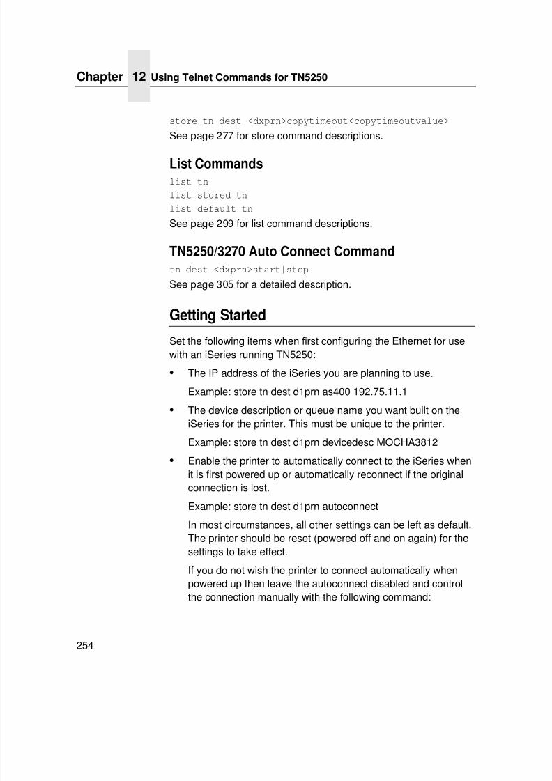
7/23/2019 54458302 IBM 6400
http://slidepdf.com/reader/full/54458302-ibm-6400 256/349
Chapter 12 Using Telnet Commands for TN5250
254
store tn dest <dxprn>copytimeout<copytimeoutvalue>
See page 277 for store command descriptions.
List Commandslist tn
list stored tn
list default tn
See page 299 for list command descriptions.
TN5250/3270 Auto Connect Command
tn dest <dxprn>start|stopSee page 305 for a detailed description.
Getting Started
Set the following items when first configuring the Ethernet for usewith an iSeries running TN5250:
• The IP address of the iSeries you are planning to use.
Example: store tn dest d1prn as400 192.75.11.1
• The device description or queue name you want built on theiSeries for the printer. This must be unique to the printer.
Example: store tn dest d1prn devicedesc MOCHA3812
• Enable the printer to automatically connect to the iSeries whenit is first powered up or automatically reconnect if the originalconnection is lost.
Example: store tn dest d1prn autoconnect
In most circumstances, all other settings can be left as default.The printer should be reset (powered off and on again) for thesettings to take effect.
If you do not wish the printer to connect automatically whenpowered up then leave the autoconnect disabled and controlthe connection manually with the following command:
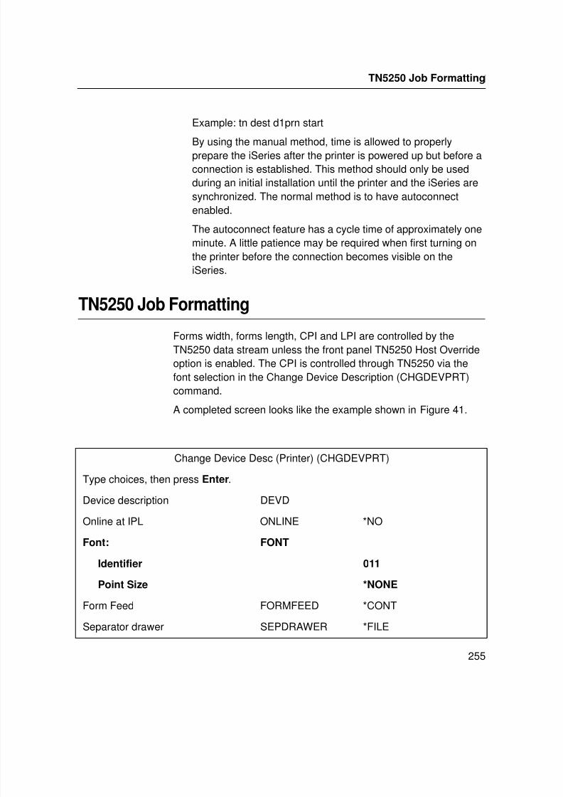
7/23/2019 54458302 IBM 6400
http://slidepdf.com/reader/full/54458302-ibm-6400 257/349
Getting Started
255
Example: tn dest d1prn start
By using the manual method, time is allowed to properlyprepare the iSeries after the printer is powered up but before aconnection is established. This method should only be usedduring an initial installation until the printer and the iSeries aresynchronized. The normal method is to have autoconnectenabled.
The autoconnect feature has a cycle time of approximately oneminute. A little patience may be required when first turning onthe printer before the connection becomes visible on theiSeries.
TN5250 Job Formatting
Forms width, forms length, CPI and LPI are controlled by theTN5250 data stream unless the front panel TN5250 Host Overrideoption is enabled. The CPI is controlled through TN5250 via thefont selection in the Change Device Description (CHGDEVPRT)command.
A completed screen looks like the example shown in Figure 41.
Change Device Desc (Printer) (CHGDEVPRT)
Type choices, then press Enter.
Device description DEVD
Online at IPL ONLINE *NO
Font: FONT
Identifier 011
Point Size *NONE
Form Feed FORMFEED *CONT
Separator drawer SEPDRAWER *FILE
TN5250 Job Formatting
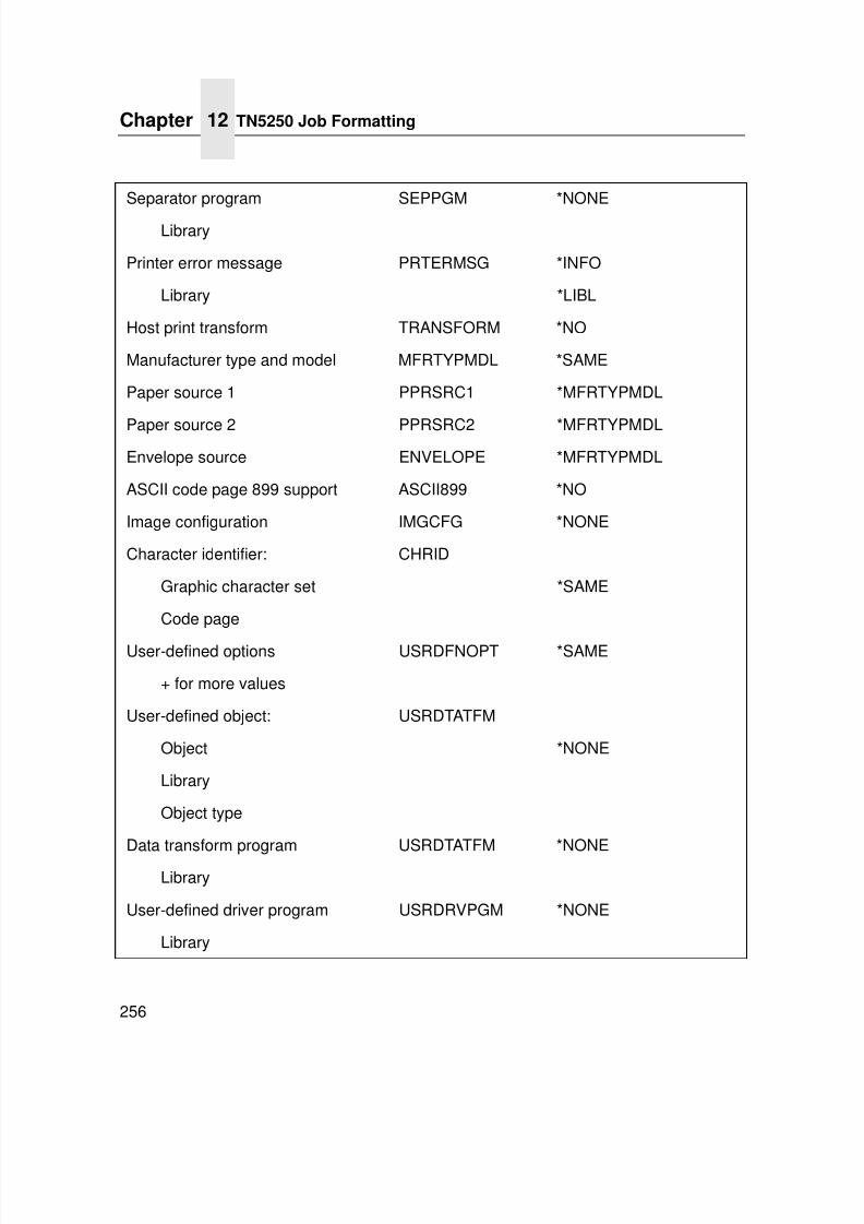
7/23/2019 54458302 IBM 6400
http://slidepdf.com/reader/full/54458302-ibm-6400 258/349
Chapter 12 TN5250 Job Formatting
256
Separator program SEPPGM *NONE
Library
Printer error message PRTERMSG *INFO
Library *LIBL
Host print transform TRANSFORM *NO
Manufacturer type and model MFRTYPMDL *SAME
Paper source 1 PPRSRC1 *MFRTYPMDL
Paper source 2 PPRSRC2 *MFRTYPMDLEnvelope source ENVELOPE *MFRTYPMDL
ASCII code page 899 support ASCII899 *NO
Image configuration IMGCFG *NONE
Character identifier: CHRID
Graphic character set *SAME
Code page
User-defined options USRDFNOPT *SAME
+ for more values
User-defined object: USRDTATFM
Object *NONE
Library
Object type
Data transform program USRDTATFM *NONELibrary
User-defined driver program USRDRVPGM *NONE
Library
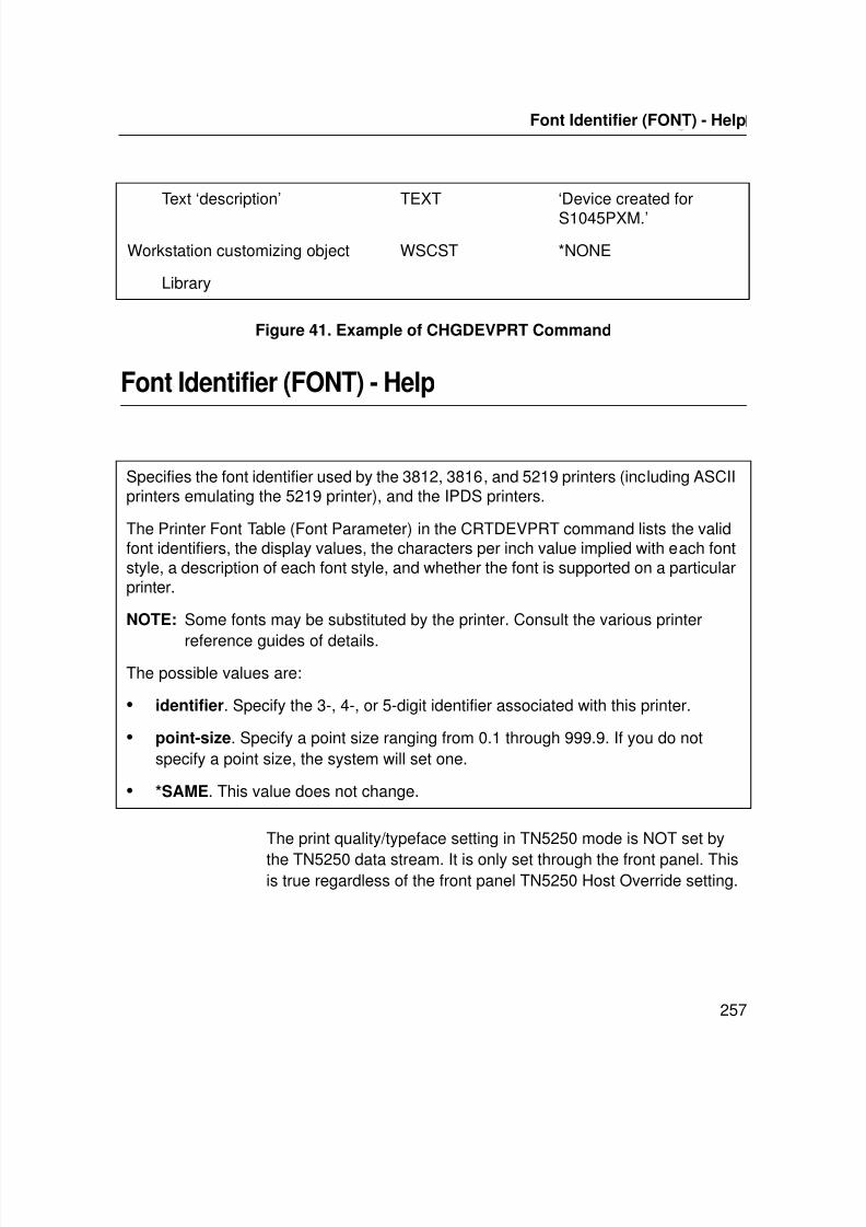
7/23/2019 54458302 IBM 6400
http://slidepdf.com/reader/full/54458302-ibm-6400 259/349
Getting Started
257
Figure 41. Example of CHGDEVPRT Command
Font Identifier (FONT) - Help
The print quality/typeface setting in TN5250 mode is NOT set by
the TN5250 data stream. It is only set through the front panel. Thisis true regardless of the front panel TN5250 Host Override setting.
Text ‘description’ TEXT ‘Device created for
S1045PXM.’
Workstation customizing object WSCST *NONE
Library
Specifies the font identifier used by the 3812, 3816, and 5219 printers (including ASCIIprinters emulating the 5219 printer), and the IPDS printers.
The Printer Font Table (Font Parameter) in the CRTDEVPRT command lists the validfont identifiers, the display values, the characters per inch value implied with each fontstyle, a description of each font style, and whether the font is supported on a particularprinter.
NOTE: Some fonts may be substituted by the printer. Consult the various printer
reference guides of details.The possible values are:
• identifier. Specify the 3-, 4-, or 5-digit identifier associated with this printer.
• point-size. Specify a point size ranging from 0.1 through 999.9. If you do notspecify a point size, the system will set one.
• *SAME. This value does not change.
Font Identifier (FONT) - Help

7/23/2019 54458302 IBM 6400
http://slidepdf.com/reader/full/54458302-ibm-6400 260/349
Chapter 12 Font Identifier (FONT) - Help
258
7/23/2019 54458302 IBM 6400
http://slidepdf.com/reader/full/54458302-ibm-6400 261/349
259
13 SNMP Installation Instructions
Configuring for a *LAN 3812 SNMP Device DescriptionSupport for SNMP is available in the base code for iSeriesOS V4RS and above. *LAN 3812 SNMP device descriptions aresimilar to *LAN 3812 PJL device descriptions, and they fully supportthe page range function.
Configuration Instructions
To configure a 6400i, for SNMP system device driver program, use
the CRTDEVPRT command. The following parameters should bespecified:
Device Class (DEVCLS)
This needs to be set to *LAN.
Device Type (TYPE)
This needs to be set to 3812.
Device Model (MODEL)This needs to be set to 1.
LAN Attachment (LANATTACH)
This needs to be set to *IP.
7/23/2019 54458302 IBM 6400
http://slidepdf.com/reader/full/54458302-ibm-6400 262/349
Chapter 13 Configuring for a *LAN 3812 SNMP Device Description
260
Port number (PORT)
This needs to be set to 9100.
Font (FONT) = 011
This is typically set to 011, which is the default 10 CPI font. A fontID is required to create the device description. Unless specialrequirements in your operation dictate something different, thisshould suffice.
Form Feed (FORMFEED)
This should be set to *CONT. Leaving this set at *TYPE or setting itto the wrong value can cause problems with both drawer selectionand paper size.
Printer Error Message (PRTERRMSG)
This defaults to *INQ, but can be set to *INFO so the printer'smessage queue will receive informational messages wheneverpossible. If this is set to *INQ and a problem occurs on the printer(such as out of forms or a paper jam) a message will be sent to the
printer's message queue that must be answered before printing cancontinue.
Activation Timer (ACTTMR)
This defaults to 170 (seconds), but can be set to any value from 1to 2550 seconds (or 42.5 minutes). The activation timer refers tothe amount of time for the system to wait for the LAN-attachedprinter device to respond before ending a connection attempt. If theprinter refuses a connection attempt by the host for any reasonbefore the timer expires, it will be considered not available and an
error message will post.
7/23/2019 54458302 IBM 6400
http://slidepdf.com/reader/full/54458302-ibm-6400 263/349
Configuration Instructions
261
Inactivity Timer (INACTTMR)
This defaults to *ATTACH, but can be set to any value from 1 to 30(minutes), as well as *SEC15 (15 seconds), *SEC30 (30 seconds)or *NOMAX (no maximum). This value determines when the printdriver closes the connection to the printer (freeing it up to receivedspooled output from another source) once there are no iSeries OSspooled files left in RDY (ready) status. It is recommended that thisbe set to *SEC15 so the iSeries OS will free up the printer 15seconds after all RDY spooled files have been processed. Setting itto *NOMAX will cause the iSeries OS to maintain the connectionuntil the writer ends, so the printer device will not be shared with
other systems.
Host Print Transform (TRANSFORM)
This needs to be set to *YES so the iSeries OS system's Host PrintTransform (HPT) function will convert both SCS and AFPDSspooled files to the printer's data stream.
Manufacturer Type and Model (MFRTYPMDL)
This indicates the type of ASCII printer being used. This value is
used by HPT to determine what ASCII controls to use whenconverting the spooled file from SCS or AFPDS to ASCII. Therecommended values are determined by the ASCII emulationsetting on the printer. The choices are: *IBM6400iEP for Epsonemulation, *IBM6400i or *IBM4203 for Proprinter.
Remote Location (RMTLOCNAME)
This should be set to the printer's IP address, host name or DNSname. If an IP address is used, it should be entered without leadingzeros (for example, use 192.186.10.2 instead of 192.186.010.002).If an IP address is used, verify that the iSeries OS can reach theprinter by using either the PING or Verify TCP/IP Connection(VFYTCPCNN) command with that IP address. If a host name orDNS name is used, verify that the iSeries OS can reach the printerby using either the PING or Verify TCP/IP Connection(VFYTCPCNN) command with that host name or DNS name.
7/23/2019 54458302 IBM 6400
http://slidepdf.com/reader/full/54458302-ibm-6400 264/349
Chapter 13 Configuring for a *LAN 3812 SNMP Device Description
262
User-Defined Options (USRDFNOPT)
Specifies, for spooled output only, one or more user-definedoptions to be used by user applications, user-specified programs orthe writer. A maximum of four user-defined options can bespecified. This should be set to *IBMSHRCNN wheneverconfiguring a *LAN 3812 SNMP.
Specifying *IBMSHRCNN will cause the print driver to open andclose the connection to the data port on the printer for every copy ofevery spooled file. This allows multiple writers and systems toaccess the printer, while the print driver is active and there are files
in ready status. When this option is specified, the printer is capableof being shared and the value that is specified for the InactivityTimer is ignored.
System Driver Program (SYSDRVPGM)
Specifies the name of a system-defined driver program, whichprovides the capability to send the iSeries OS printer output to aprinter attached over a TCP/IP network. This should be set to*IBMSNMPDRV whenever configuring a *LAN 3812 SNMP devicedescription.
Workstation Customizing Object (WSCST)
This is typically set to *NONE, but can be used to specify amodified workstation customer object.
All other parameters should be specified like any other printer.
7/23/2019 54458302 IBM 6400
http://slidepdf.com/reader/full/54458302-ibm-6400 265/349
Configuration Instructions
263
Configuration Example
To configure a *LAN 3812 SNMP device description typeCRTDEVPRT and press the F4 (Prompt) key. The following is anexample of using the Create Device Printer (CRTDEVPRT)command to create a *LAN 3812 SNMP device description:
CRTDEVPRT DEVD(SNMP6400i) DEVCLS(*LAN) TYPE(3812)MODEL(1) LANATTACH(*IP) PORT(9001) FONT(011)FORMFEED(*CONT) PARITY(*NONE)STOPBITS(1)TRANSFORM(*YES)MFRTYPMDL(*IBM6400i)RMTLOCNAME('9.5.208.46') USRDFNOPT(*IBMSHRCNN) USRDRVPGM(*NONE)SYSDRVPGM(*IBMSNMPDRV)
Create Device Desc (Printer) (CRTDEVPRT)
Type choices, then press Enter.
Device description SNMP6400i Name
Device class *LAN *LCL, *RMT, *VRT, *SNPT, *LAN
Device type 3812 3287, 3812, 4019, 4201...
Device model 1 0, 1, 2, 3, 4, 10, 13, 301...
LAN attachment *IP *LEXLINK, *IP, *USRDFN
Port number 9100 0-65535
Online at IPL *YES *YES, *NO
Font:
Identifier 11 3, 5, 11, 12, 13, 18, 19...
Point size *NONE 000.1-999.9, *NONE
Form feed *CONT *TYPE, *CONT, *CONT2, *CUT...
Separator drawer *FILE 1-255, *FILE
Separator program *NONE Name, *NONE
Library Name, *LIBL, *CURLIB
Printer error message *INFO *INQ, *INFO
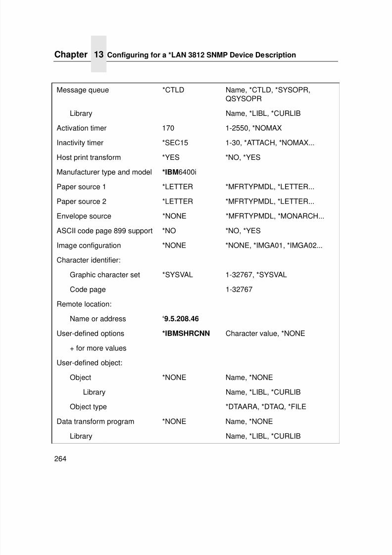
7/23/2019 54458302 IBM 6400
http://slidepdf.com/reader/full/54458302-ibm-6400 266/349
Chapter 13 Configuring for a *LAN 3812 SNMP Device Description
264
Message queue *CTLD Name, *CTLD, *SYSOPR,
QSYSOPR
Library Name, *LIBL, *CURLIB
Activation timer 170 1-2550, *NOMAX
Inactivity timer *SEC15 1-30, *ATTACH, *NOMAX...
Host print transform *YES *NO, *YES
Manufacturer type and model *IBM6400i
Paper source 1 *LETTER *MFRTYPMDL, *LETTER...
Paper source 2 *LETTER *MFRTYPMDL, *LETTER...
Envelope source *NONE *MFRTYPMDL, *MONARCH...
ASCII code page 899 support *NO *NO, *YES
Image configuration *NONE *NONE, *IMGA01, *IMGA02...
Character identifier:
Graphic character set *SYSVAL 1-32767, *SYSVAL
Code page 1-32767Remote location:
Name or address ‘9.5.208.46
User-defined options *IBMSHRCNN Character value, *NONE
+ for more values
User-defined object:
Object *NONE Name, *NONE
Library Name, *LIBL, *CURLIB
Object type *DTAARA, *DTAQ, *FILE
Data transform program *NONE Name, *NONE
Library Name, *LIBL, *CURLIB
7/23/2019 54458302 IBM 6400
http://slidepdf.com/reader/full/54458302-ibm-6400 267/349
Varying on the Printer
265
Varying on the Printer
Once you have created the printer device description, you need tovary on the printer device description using either the VaryConfiguration (VRYCFG) command or Work with ConfigurationStatus (WRKCFGSTS) command. Once the device has been
varied on, you must start the printer writer using either(STRPRTWTR) or Work with Writers (WRKWTR) command.
Problem Areas for Consideration
If you then place a spooled file in the printer's output queue and itgoes to MSGW (message wait) status with MSGCPA3394 “Loadform type '&4' device &5 writer &1. (G B I H R C)” then chances aregood that the spooled file will print once you answer this messagewith a “G.”
However, if the spooled file stays in RDY (ready) status or goes toPND (pending) status without printing or if the WTR ends you canlook in the Message queue you specified in the devd, the SYSOPRmessage queue or the writer job log for messages that mayindicate why the spooled file is not printing or why the WTR ended.
To look in the message queue you specified in the devd or theSYSOPR message queue, simply Type, DSPMSG, then press F4 (toPrompt the cmd) and enter either your queue name/library or*SYSOPR. You should see the a message indicating that the job
was submitted and then above that the failure. You may press F1on that message to obtain the second level text. If you are referredto the WTR job log for additional information, refer to the followinginstructions.
System driver program *IBMSNMPDRV
Text ‘description’ ‘*LAN 3218 SNMP DeviceDescription for IBM 6400i’
7/23/2019 54458302 IBM 6400
http://slidepdf.com/reader/full/54458302-ibm-6400 268/349
Chapter 13 Configuring for a *LAN 3812 SNMP Device Description
266
To look at the writer job, do the following:
NOTE: Check to see if the writer is still active.
1. On the iSeries OS command line, type the following:
WRKJOB JOB(writer-name) The writer name is typically thesame name given to the device description. Press the Enterkey. This brings you to the Select Job panel or the Work withJob panel. If you are at the Select Job panel, the most currentwriter job is at the top of the list. Place a 1 in the Option field tothe left of the most recent WTR job and press the Enter key.
If the writer has ended, take menu option 4 (Work with spooled
files) on the Work with Job panel. From the Work with JobSpooled Files panel, select Option 5 (Display) to display theQPJOBLOG spooled file or Option 2 (Change) to requeue thespooled file to a different output queue so it can be printed andinvestigated. Make any suggested corrections, restart thewriter, and re-submit the job.
If the writer is still active, select menu option 10 (Display joblog, if active or on job queue) on the Work with Job panel.Press the F10 key and the Page Up and Page Down keys toview the messages in the writer job log.
Additional Information
The success of *LAN 3812 SNMP device descriptions is dependenton the configuration settings in the iSeries OS as well as on theprinter and print server hardware. For more information aboutconfiguring the time-out values on the printer and print serverhardware and common error messages that you can receive whenprinting through a *LAN 3812 SNMP device description, pleaserefer to the following document:
19935220 Configuration Settings and Error Messages for *LAN3812 SNMP Device Descriptions located on the iSeries support lineKnowledge base Web site.
7/23/2019 54458302 IBM 6400
http://slidepdf.com/reader/full/54458302-ibm-6400 269/349
267
14 Monitoring Printers
Implementing Printer Management
Printer management includes the following tasks:
• Monitoring the status of network printers
• Responding to alarms
• Gathering statistics on printer operations
The three elements of network printer monitoring and managementare:
• Agent/manager model
• The management information database (MIB)
• SNMP, the protocol used to get management information• Printer management utility (PMU)
Agent/Manager Model
The elements of a monitoring system, MIB and SNMP, areimplemented in an agent/manager model:
• The MANAGER is a console, workstation, or server on workinghubs or routers which has a global knowledge of Ethernet
Interfaces and printers.• AGENTS are utilities that reside on devices, such as a Ethernet
Interface, that respond through SNMP to managementrequests for information. The information is stored in an MIB.
7/23/2019 54458302 IBM 6400
http://slidepdf.com/reader/full/54458302-ibm-6400 270/349
Chapter 14 Implementing Printer Management
268
MIB
An MIB contains information a device makes available throughSNMP. The MIB is a management information base that describesinformation about actual objects to be managed and controlled.
Standards Of Network Printer MIBs
The Printer MIB is based on the following standards:
• System and Interfaces Group MIB (RFC 1213 of March 1991)
• Host Resource MIB (RFC 1514 of September 1993)
• Printer MIB (RFC 1759 of March 1995)
Components Of The Printer MIB
The printer MIB gives the network manager access to most of theinformation that is normally accessible through the EthernetInterface command set for configuring the server with SNMP. Someobjects identified by this MIB are not applicable to the EthernetInterface.
The printer MIB is composed of the following sections:
• General
• Cover
• Localization
• Input
• Output
• Marker
• Media Path
• Channel
• Interpreter
• Console
• Alert
7/23/2019 54458302 IBM 6400
http://slidepdf.com/reader/full/54458302-ibm-6400 271/349
MIB
269
Information Provided By The MIB
The printer MIB contains the following types of information aboutnetwork printers:
Descriptions. Printer configuration, location, and contact.
Status. Current operating status of printers.
Alerts. Reportable events from printers.
General Information About MIBs
For further information on SNMP and MIB, refer to the following:• RFC 1155 — Structure and Identification of Management
Information for TCP/IP-based Internets (SMI)
• RFC 1156 — Management Information Base for Managementof TCP/IP Internets (MIB)
• RFC 1157 — A Simple Network Management Protocol (SNMP)
• The Simple Book: An Introduction to Management ofTCP/IP-based Internets
Getting The Latest MIB InformationTo obtain the latest copy of these and other RFCs, FTP the filesfrom one of the following two sources:
Internet:ftp://ftp.isi.edu/internet-drafts
World Wide Web:http://www.ietf.cnri.reston.va.us/lid-abstracts.html
7/23/2019 54458302 IBM 6400
http://slidepdf.com/reader/full/54458302-ibm-6400 272/349
Chapter 14 Monitoring Tools
270
SNMP
SNMP is the protocol used to communicate between manager andagent. Managers request information, usually through automatedpolling at specified intervals, and agents respond. Though usedprimarily on TCP/IP networks, SNMP can be implemented on otherprotocols, for example, IPX.
SNMP is a standard by which a network manager can get statisticsand configuration information from the Ethernet Interfaces andother devices on the network. This is done through a NetworkManagement Station (NMS) such as NetView ® .
The Printer Management Utility Software (PMU)
The IBM printer manager utility is a versatile and dynamic program.It allows you to organize all of the printers in your office remotely ina single database, download software and printer settings from ahost computer with a single mouse click, and use a virtualoperator's panel to configure printers in the same room or on theother side of the world. Refer to IBM Printer Management Utility User’s Manual for more details on this tool.
Monitoring Tools
Many tools can be used to monitor printers with SNMP agents. Oneof these tools is NetView. There are also other MIB browsers whichare not described here.
OS/2 TCP/IP
To get SNMP.EXE to work correctly to browse MIB items, you mayneed to delete the following file:
d:\mptn\etc\mib2.tbl
7/23/2019 54458302 IBM 6400
http://slidepdf.com/reader/full/54458302-ibm-6400 273/349
Monitoring With AIX NetView/6000
271
Monitoring With AIX NetView/6000
The AIX NetView/6000 program can manage any IP-addressabledevice with an SNMP agent.
NetView/6000 can be used to set a network topology, monitor anetwork, diagnose problems, and measure network performance.
Through its MIB Browser, information about the resources affectingan event (such as an alarm) can be obtained.
Setting The SNMP Community Name
The default SNMP read-only community name is “public” andcannot be changed.
Change the SNMP R/W community name with the command:set user passwd snmp com_name
save
where com_name is the new SNMP R/W community name.
The default is no R/W community name.
NOTE: Changing SNMP community names or access rights may
hinder or disable applications that are monitoring yourprinters.

7/23/2019 54458302 IBM 6400
http://slidepdf.com/reader/full/54458302-ibm-6400 274/349
Chapter 14 Monitoring Tools
272
7/23/2019 54458302 IBM 6400
http://slidepdf.com/reader/full/54458302-ibm-6400 275/349
273
15 IBM Network Printer Manager
OverviewIBM Network Printer Manager (NPM) lets network administratorsmonitor, control, and configure IBM 6400i printers in variousenvironments. NPM works with the IBM 6400i, the network printerfamily, including IBM Infoprint 20 and 32 (except for NPM for OS/2),and IBM Network Printers 12, 17, and 24. For the Windows and IPand Web versions, you can also use NPM with othermanufacturer’s network printers that comply with RFC 1759, suchas the Hewlett-Packard** LaserJet** 5si and the Lexmark**Optra** N.
NOTE: IBM 6400i is supported only in the “web” and NT versions,not OS/2.
Using NPM, administrators can:
• View the status of each printer, such as its alarm conditions
• View and change printer properties, such as the default inputtray
• View and change printer network properties, such as theNetBIOS printer network workgroup name
• Add new network services to printers so you can customize theenvironment, such as creating high- and low-priority printservices.
For detailed information on how to use NPM, please refer to NPMonline help.
7/23/2019 54458302 IBM 6400
http://slidepdf.com/reader/full/54458302-ibm-6400 276/349
Chapter 15 IBM Network Printer Manager
274
You can configure NPM using either the TCP/IP or NetBIOS
network protocols, and use TCP/IP to monitor the printers.NPM is available on the World Wide Web. To obtain the latestversion of NPM:
1. Access the IBM Printing Systems Home Page at:http://www.printers.ibm.com
2. Navigate to IBM Network Printer Manager.
3. Follow the instructions to download NPM. Installationinstructions are in the README file.
NOTE: NPM for Windows NT requires that a specific SNMP R/Wcommunity name be defined in the printer before it can besuccessfully discovered. The SNMP R/W community namemust be set to ibmpsc_admin with the following telnetcommands:
set user passwd snmp ibmpsc_admin
save
7/23/2019 54458302 IBM 6400
http://slidepdf.com/reader/full/54458302-ibm-6400 277/349
275
16 Commands
Command Shell Overview
The Ethernet Interface comes with an in-depth command shell
called npsh. It allows you to manipulate objects like destinations,I/O ports, and models and provides monitoring and troubleshootingcapabilities.
npsh Access Methods
This command shell can be accessed by:
• built in HTML forms
• a Telnet session from a TCP/IP host to the Ethernet Interface
• a single remote shell command (e.g., rsh, rcmd, remsh) froma TCP/IP host
Main npsh Command Prefixes
All configurable commands either start with store or set, andview commands start with list.
NOTE: If the store prefix is used, the Ethernet Interface must berepowered to make the changes take effect. Since store
affects flash memory settings only, the print server mustreset and read the new settings now in flash memory.
7/23/2019 54458302 IBM 6400
http://slidepdf.com/reader/full/54458302-ibm-6400 278/349
Chapter 16 Complete Command List
276
NOTE: If the set prefix is used, a save command must be
executed as well so that the new settings are retained afterpower cycles. Since set only affects the settings inmemory, they will be lost after a power cycle unless theyare saved to flash memory.
Getting Command Help
The Ethernet Interface command shell provides several online helptools, including:
“?” CommandTyping “?” when logged in to the command shell will produce a fulllist of all available commands.
Command Prefixes
Typing in the first portion of a command will produce an errormessage showing the correct syntax. For example, typing in storetcpip will produce a list of all commands that start with this prefix.
Complete Command List
This section outlines the entire Ethernet Interface command setincluding the command syntax, a description, and in most cases, anexample for each command listed.
NOTE: If you see the word ifnum in any npsh commands, youshould substitute a 1 unless told otherwise. This 1 represents the one network interface (e.g., Ethernet)supported.
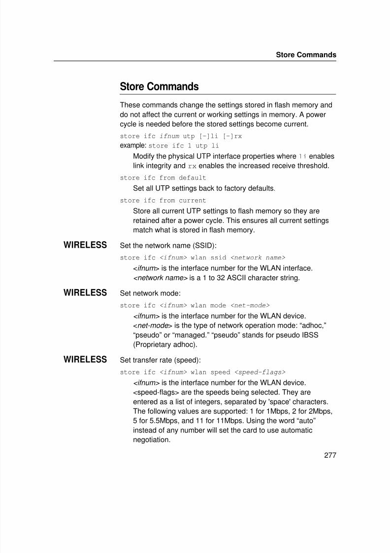
7/23/2019 54458302 IBM 6400
http://slidepdf.com/reader/full/54458302-ibm-6400 279/349
Store Commands
277
Store Commands
These commands change the settings stored in flash memory anddo not affect the current or working settings in memory. A powercycle is needed before the stored settings become current.
store ifc ifnum utp [-]li [-]rx
example: store ifc 1 utp li
Modify the physical UTP interface properties where li enableslink integrity and rx enables the increased receive threshold.
store ifc from default
Set all UTP settings back to factory defaults.
store ifc from current
Store all current UTP settings to flash memory so they areretained after a power cycle. This ensures all current settingsmatch what is stored in flash memory.
WIRELESS Set the network name (SSID):
store ifc <ifnum> wlan ssid <network name>
<ifnum > is the interface number for the WLAN interface.<network name> is a 1 to 32 ASCII character string.
WIRELESS Set network mode:
store ifc <ifnum> wlan mode <net-mode>
<ifnum> is the interface number for the WLAN device.<net-mode > is the type of network operation mode: “adhoc,”“pseudo” or “managed.” “pseudo” stands for pseudo IBSS(Proprietary adhoc).
WIRELESS Set transfer rate (speed):
store ifc <ifnum> wlan speed <speed-flags>
<ifnum> is the interface number for the WLAN device.<speed-flags> are the speeds being selected. They areentered as a list of integers, separated by 'space' characters.The following values are supported: 1 for 1Mbps, 2 for 2Mbps,5 for 5.5Mbps, and 11 for 11Mbps. Using the word “auto”instead of any number will set the card to use automaticnegotiation.
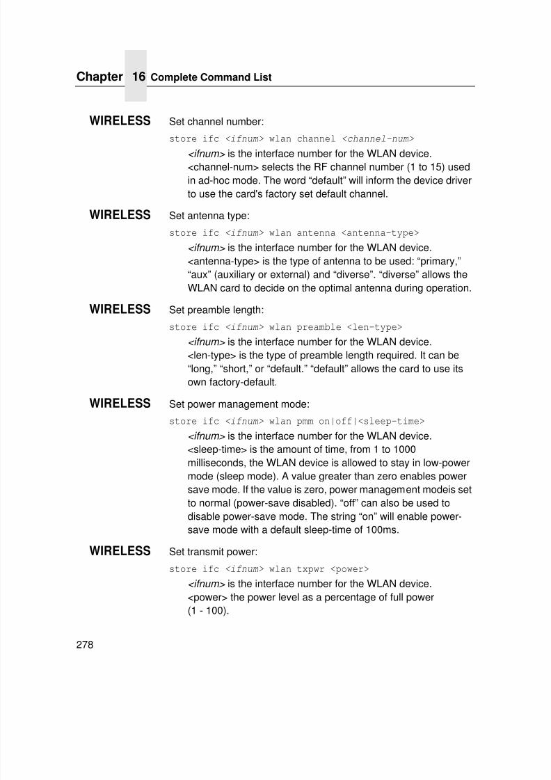
7/23/2019 54458302 IBM 6400
http://slidepdf.com/reader/full/54458302-ibm-6400 280/349
Chapter 16 Complete Command List
278
WIRELESS Set channel number:
store ifc <ifnum> wlan channel <channel-num>
<ifnum> is the interface number for the WLAN device.<channel-num> selects the RF channel number (1 to 15) usedin ad-hoc mode. The word “default” will inform the device driverto use the card's factory set default channel.
WIRELESS Set antenna type:
store ifc <ifnum> wlan antenna <antenna-type>
<ifnum> is the interface number for the WLAN device.<antenna-type> is the type of antenna to be used: “primary,”
“aux” (auxiliary or external) and “diverse”. “diverse” allows theWLAN card to decide on the optimal antenna during operation.
WIRELESS Set preamble length:
store ifc <ifnum> wlan preamble <len-type>
<ifnum> is the interface number for the WLAN device.<len-type> is the type of preamble length required. It can be“long,” “short,” or “default.” “default” allows the card to use itsown factory-default.
WIRELESS Set power management mode:store ifc <ifnum> wlan pmm on|off|<sleep-time>
<ifnum> is the interface number for the WLAN device.<sleep-time> is the amount of time, from 1 to 1000milliseconds, the WLAN device is allowed to stay in low-powermode (sleep mode). A value greater than zero enables powersave mode. If the value is zero, power management modeis setto normal (power-save disabled). “off” can also be used todisable power-save mode. The string “on” will enable power-save mode with a default sleep-time of 100ms.
WIRELESS Set transmit power:
store ifc <ifnum> wlan txpwr <power>
<ifnum> is the interface number for the WLAN device.<power> the power level as a percentage of full power(1 - 100).
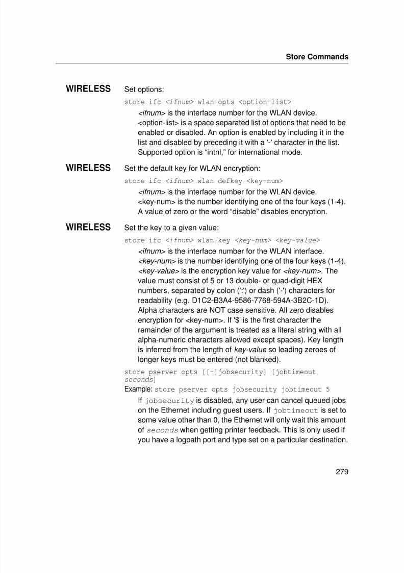
7/23/2019 54458302 IBM 6400
http://slidepdf.com/reader/full/54458302-ibm-6400 281/349
Store Commands
279
WIRELESS Set options:
store ifc <ifnum> wlan opts <option-list>
<ifnum> is the interface number for the WLAN device.<option-list> is a space separated list of options that need to beenabled or disabled. An option is enabled by including it in thelist and disabled by preceding it with a '-' character in the list.Supported option is “intnl,” for international mode.
WIRELESS Set the default key for WLAN encryption:
store ifc <ifnum> wlan defkey <key-num>
<ifnum> is the interface number for the WLAN device.
<key-num> is the number identifying one of the four keys (1-4).A value of zero or the word “disable” disables encryption.
WIRELESS Set the key to a given value:
store ifc <ifnum> wlan key <key-num> <key-value>
<ifnum> is the interface number for the WLAN interface.<key-num> is the number identifying one of the four keys (1-4).<key-value> is the encryption key value for <key-num> . Thevalue must consist of 5 or 13 double- or quad-digit HEXnumbers, separated by colon (':') or dash ('-') characters for
readability (e.g. D1C2-B3A4-9586-7768-594A-3B2C-1D).Alpha characters are NOT case sensitive. All zero disablesencryption for <key-num>. If '$' is the first character theremainder of the argument is treated as a literal string with allalpha-numeric characters allowed except spaces). Key lengthis inferred from the length of key-value so leading zeroes oflonger keys must be entered (not blanked).
store pserver opts [[-]jobsecurity] [jobtimeoutseconds]
Example: store pserver opts jobsecurity jobtimeout 5
If jobsecurity is disabled, any user can cancel queued jobson the Ethernet including guest users. If jobtimeout is set tosome value other than 0, the Ethernet will only wait this amountof seconds when getting printer feedback. This is only used ifyou have a logpath port and type set on a particular destination.
7/23/2019 54458302 IBM 6400
http://slidepdf.com/reader/full/54458302-ibm-6400 282/349
Chapter 16 Complete Command List
280
store pserver opts [[-]jobsecurity][jobtimeout <SECONDS>] [jobcontrol[off|standard|enhanced]]
Example: store pserver opts [-]jobcontrol
If jobcontrol is disabled then the need for start of job / end of job flow control with the printer is determined by the printer. Jobflow control is used for jobs requiring backchannel responsessuch as IPDS, TN and PJL jobs only. This is available as aperformance enhancement for LPR, TCP socket printing etc.The job flow control has no affect on IPDS, TN, and PJL jobs.These options perform their own control. When jobcontrol isenabled all jobs will be supported with job flow control.
NOTE: When jobcontrol is disabled, dynamic config loading on amodel change is also disabled.
• off. no job control; no SOJ/EOJ commands. The printer printsfaster in off mode.
• standard. (the default) traditional job control with immediateacknowledgements of SOJ/EOJ commands.
• enhanced. job control with EOJ acknowledgements held off bythe printer until job is fully printed. The printer prints slower in
enhanced mode.To monitor the printer, use the telnet command “lpstat.” The normalstatus reported on the first line of the lpstat response is the status ofthe queue (LPQ) within the Ethernet. The status reported does notreflect the state of the print job once it has been sent from theEthernet to the printer.
The new line at the bottom of the lpstate response labeled “printer job:” can report one of two status values:
a. In Progress. A job in the printer is not yet finished.
b. Done. There are no jobs in the printer. All previous jobs arefinished.
7/23/2019 54458302 IBM 6400
http://slidepdf.com/reader/full/54458302-ibm-6400 283/349
Store Commands
281
store pserver lpd [-]dest1default
Example: store pserver lpd dest1defaultIf dest1default is disabled and upon verification, the printername supplied by the LPR protocol and the destination namedoes not match, then an error message is returned and theservice is refused. If dest1default is enabled and uponverification, the printer name supplied by the LPR protocol andthe destination name does not match, then the job isautomatically routed to the first destination and the service isaccepted.
Default: enabled
store pserver tcpsocket TCPportnumber port newTCPportnumber
Example: store pserver tcpsocket 4000 port 5000
Change a pre-defined TCPportnumber on the EthernetInterface to a newTCPportnumber . The default number is9100 for prn.
store pserver tcpsocket TCPportnumber dest destination
Example: store pserver tcpsocket 5000 dest d1prn
Assign a pre-defined TCPportnumber to a particulardestination
on the Ethernet Interface. Therefore, if you areusing a print method that sends jobs directly to a TCP portnumber, you still have the option to process the job datathrough this destination setting.
ADAPTER,WIRELESS
store pserver novell passwd password
Example: store pserver novell passwd mplex
Store the password for the Ethernet Interface to use whenlogging in to a Novell file server. This password would have tomatch one set on the file server.
ADAPTER,WIRELESS
store pserver novell fserver add|del fileservernameExample: store pserver novell fserver add fs1
Add or remove a server entry on the Ethernet Interface for theNovell file server it will be servicing.
7/23/2019 54458302 IBM 6400
http://slidepdf.com/reader/full/54458302-ibm-6400 284/349
Chapter 16 Complete Command List
282
ADAPTER,
WIRELESS
store pserver novell frametype [ethernet2|802.2|802.3|
802.2 smap|autosense]Sets the frame type for the Novell protocol.
store pserver smb workgrp newworkgroupname
Example: store pserver smb workgrp eng
Define a different Windows workgroup as defined bynewworkgroupname for the Ethernet Interface to be visiblewithin (should be 14 characters or less). By default, the printserver only comes up within the group called “WORKGROUP.”
store pserver from default
Set all general print server settings back to factory defaults.
store pserver from current
Store all current general print server settings to flash memoryso they are retained after a power cycle. This ensures allcurrent settings match what is stored in flash memory.
ADAPTER,WIRELESS
store rprinter add|del printservername printernumber destination
Example: store rprinter add pserver1 0 d1prn
Add or delete the RPRINTER settings on the Ethernet Interfacefor a Novell environment. The printservername must be the
name of an existing PSERVER.NLM on your Novell file server.The printernumber is the printer number within thisPSERVER.NLM. The destination is the queue on theEthernet Interface where the print jobs will be sent to.
store tcpip ifnum addr IPaddress
Example: store tcpip 1 addr 192.75.11.9
Store the IP address for the Ethernet Interface.
store tcpip ifnum mask netmask
Example: store tcpip 1 mask 255.255.255.0
Store the subnet mask for the Ethernet Interface.
7/23/2019 54458302 IBM 6400
http://slidepdf.com/reader/full/54458302-ibm-6400 285/349
Store Commands
283
store tcpip ifnum opts [[-]rarp] [[-]bootp] [[-]dhcp][[-]dms]
Example: store tcpip 1 opts -rarp -bootp -dhcp
Enable or disable the automatic RARP, BOOTP, DHCP, orDNS requests for IP addresses upon bootup. If you are storingthe Ethernet Interface TCP/IP network settings within thedevice, you will not need to rely on RARP, BOOTP, DHCP, orDNS for new settings.
store tcpip ifnum frametype [[-]ethernet2][[-]802.2snap]
Example: store tcpip 1 frametype ethernet2 802.2snap
Control which frame type(s) is supported with the TCP/IPprotocol. By default, both Ethernet2 and 802.2snap areenabled, but normal TCP/IP communications rely on Ethernet2. This setting has no affect on other supported networkprotocols (e.g., Novell).
store tcpip route add|del host|net IPaddress ifnum
Example: store tcpip route add net 192.75.12.0 1
Add or delete a static route to a particular TCP/IP host orsubnet specified by IPaddress so the Ethernet Interfaceknows how to communicate with it. Normally one entry for a
default router/gateway is all that is needed for communicationsbetween different subnets. Please see the next command fordetails.
store tcpip route add|del default routerIPaddress ifnum
Example: store tcpip route add default 192.75.11.1 1
Store a default router/gateway defined by routerIPaddress so the Ethernet Interface knows where to direct packetsdestined for another subnet. It is easier to store one defaultentry rather than an entry per remote host or network as in theprevious command.
store tcpip tcp rxwin packets
Example: store tcpip tcp rxwin 2
Determine the receive window size for the Ethernet Interface.Usually the packets value ranges from 2 to 8, with the lowernumber allowing for more simultaneous TCP connections withthe print server.
7/23/2019 54458302 IBM 6400
http://slidepdf.com/reader/full/54458302-ibm-6400 286/349
Chapter 16 Complete Command List
284
store tcpip tcp opts [-]keepalive [-]disbufmgmt[-]zeroIArp [-]keepalivedata
Example: store tcpip tcp opts keepalive -disbufmgmt
Control whether the Ethernet Interface maintains a connectionwith a host when data cannot be accepted into its buffer.Normally the keepalive feature is enabled so when theprinter cannot accept data, the print job connection ismaintained and continued once the situation clears. Thekeepalivedata option controls whether the keepalive packetcontains a data byte for hosts that require it. If disbufmgmt isdisabled (i.e., “-”), the Ethernet Interface will not buffer any data
when there is a blocked situation with the printer. Normally, it isbest to have both keepalive and disbufmgmt enabled.
Example: store tcpip tcp opts zeroIPArp
If zeroIPArp is disabled then a Ethernet Interface with an IPaddress of 0.0.0.0 will not allow IP access until the IP addressis configured. If zeroIPArp is enabled on an Ethernet Interfacewith an IP address of 0.0.0.0 then any attempted access with avalid IP address is assumed for this Ethernet Interface and anArp lookup is performed.
Default: enabled
store tcpip tcp access [root] add|del IPaddress
Example: store tcpip tcp access add 192.75.11.25
Add or remove an entry from the Ethernet Interface TCPaccess list defined by IPaddress. If the list has an entry, onlythis host can print to and remotely interact with the print server.
store tcpip from default|current
Example: store tcpip from default
Set all TCP/IP network settings back to factory defaults.
Example: store tcpip from current
Store all current TCP/IP network settings to flash memory sothey are retained after a power cycle. This ensures all currentsettings match what is stored in flash memory.
7/23/2019 54458302 IBM 6400
http://slidepdf.com/reader/full/54458302-ibm-6400 287/349
Store Commands
285
store tn dest destination connect resourcename
Example: store tn dest d1prn connect MYRESNMStore the resource name for the host session. The resourcename must be the same as the name of the printer devicecreated on the host for the session.
Default: Unconfigured (empty) resource name
store tn dest destination mode 5250|3270
Example: store tn dest d1prn mode 3270
Store the TN protocol mode.
Default: 5250
store tn dest destination host IPaddress
Example: store tn dest d1prn host 192.75.11.1
Store the IP address of the TN5250/3270 host
Default: Unconfigured (empty) IP address
store tn dest destination port portnumber
Example: store tn dest d1prn port 27
Store the UDP port number of the TN server.
Default: 23
store tn dest destination devicedesc devicename
Example: store tn dest d1prn devicedesc MOCHA3812
Store the name of the printer device. The description enteredwill be the name of the printer device created on the iSerieshost for the current session.
Default: Unconfigured (empty) description.
store tn dest destination msgqname msgqname msgqlibmsgqlib
Example: store tn dest d1prn msqqname QSYSOPR msgqlib *LIBL
Store the queue name and the queue library to which systemmessages will be logged.
Default: QSYSOPR , *LIBL
7/23/2019 54458302 IBM 6400
http://slidepdf.com/reader/full/54458302-ibm-6400 288/349
Chapter 16 Complete Command List
286
store tn dest destination WSCSTname WSCSTname WSCSTlibWSCSTlib
Example: store tn dest d1prn WSCSTname *NONE WSCSTlib*LIBL
Store the queue name and the queue library to which systemmessages will be logged.
Default: *NONE , *LIBL
store tn dest destination [-]autoconnect
Example: store tn dest d1prn autoconnect
Store the state of the autoconnect flag. If the autoconnect flagis enabled the Ethernet Interface TN client will attempt a
connection and binding with the specified TN hostautomatically on power-up. This connection sequence will berepeated every 60 seconds until successful or the autoconnectflag is disabled.
See “tn dest destination start | stop” command.
Default: disabled
store tn dest destination copytimeout
Example: store tn dest d1prn copytimeout 1000
Store the value of the copytimeout. When consecutive
TN5250/3270 jobs are sent to the Ethernet, they are treateddifferently depending how soon they arrive. In an attempt toprovide a perception of collation when multiple copies are sentfrom one host, if the time between jobs is less than thecopytimeout value then they are treated as copies and the jobis given precedence over other host documents. This keepsdocuments, which are sent in rapid succession together as ifthey were copies of the same document. A higher valueimproves the likelihood of collation but impacts performance.
Default: 500
store tn dest destination from default
Example: store tn dest d1prn from default
Store all tn default settings to flash memory so that they areretained after power up.
7/23/2019 54458302 IBM 6400
http://slidepdf.com/reader/full/54458302-ibm-6400 289/349
Set Commands
287
Set Commands
These settings alter the current or working settings in memory only.Therefore, they will be lost if the Ethernet Interface is power cycled.To ensure this does not happen, issue a save command so thecurrent settings get written to flash memory.
set date year month day
Example: set date 1997 02 10
Set the current date noting the four-digit year , the two-digitmonth from 1 through 12, and the day (the number in themonth). If the Ethernet Interface is reset, this value will be lost
so you will need to set the date again.set dest destination name newname
Example: set dest d1prn name thermal
Change the current name of the destination to a new nameas indicated by newname. This newname must be ninecharacters or less or it will be truncated. These names are casesensitive.
set dest destination backchannel prn [prn]
Example: set dest d1prn backchannel prn
Establish a return path for printer feedback for a givendestination. The Ethernet Interface I/O port is bi-directional,however, you will most likely use the same I/O port to which thedestination is currently sending jobs.
set dest destination model modelname
Example: set dest d1prn model m4
Associate a model with a destination. Jobs sent to the nameddestination are processed according to the options definedin the named model.
set dest destination logpath logpathname
Example: set dest d1prn logpath l4
Associate a logpath with a destination. Jobs sent to the nameddestination are logged according to the settings defined inthe named logpath.
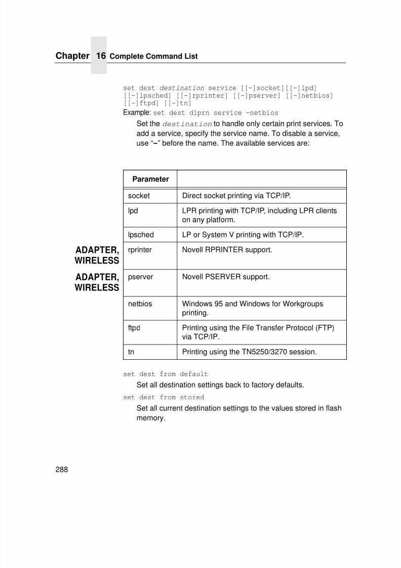
7/23/2019 54458302 IBM 6400
http://slidepdf.com/reader/full/54458302-ibm-6400 290/349
Chapter 16 Complete Command List
288
set dest destination service [[-]socket][[-]lpd][[-]lpsched] [[-]rprinter] [[-]pserver] [[-]netbios][[-]ftpd] [[-]tn]
Example: set dest d1prn service -netbios
Set the destination to handle only certain print services. Toadd a service, specify the service name. To disable a service,use “-” before the name. The available services are:
set dest from default
Set all destination settings back to factory defaults.
set dest from stored
Set all current destination settings to the values stored in flashmemory.
Parameter
socket Direct socket printing via TCP/IP.lpd LPR printing with TCP/IP, including LPR clients
on any platform.
lpsched LP or System V printing with TCP/IP.
ADAPTER,WIRELESS
rprinter Novell RPRINTER support.
ADAPTER,WIRELESS
pserver Novell PSERVER support.
netbios Windows 95 and Windows for Workgroupsprinting.
ftpd Printing using the File Transfer Protocol (FTP)via TCP/IP.
tn Printing using the TN5250/3270 session.
7/23/2019 54458302 IBM 6400
http://slidepdf.com/reader/full/54458302-ibm-6400 291/349
Set Commands
289
set logpath logpath name newname
Example: set logpath l1 name pagecountChange the current name of the logpath to a new name asindicated by newname. This newname must be nine charactersor less or it will be truncated. These names are case sensitive.
set logpath logpath type [[-]job] [[-]user] [[-]pgcnt][[-]cksum] [[-]printer] [[-]ioport]
Example: set logpath l2 type job user printer pgcnt
Establish the type of printer and print job logging to be donewithin this logpath. The options are:
job Job ID, username, etc.
user User ID along with three messages per jobabout start and finish.
pgcnt For total pages printed in a job.
cksum 16-bit checksum value to confirm integrity ofdata printed.
printer For special printer feedback.
ioport Printer error messages determined throughthe parallel port pins.
set logpath logpath port TCPportnumber | email|syslog
Example: set logpath l3 port 2000
Determine where the log information should be sent for a print job or attached printer. The choices are:
TCPportnumber TCP port number ranging from 1024 to65000.
email Particular user's email address. This addressis set using the set sysinfo email
emailname@IPaddress command.
syslog A central TCP/IP host running the SYSLOGdaemon. This host is set using the set
sysinfo syslog IPaddress command.
set logpath from default
Set all logpath settings back to factory defaults.
7/23/2019 54458302 IBM 6400
http://slidepdf.com/reader/full/54458302-ibm-6400 292/349
Chapter 16 Complete Command List
290
set logpath from stored
Set all current logpath settings to the values stored in flashmemory.
set model model name newname
Example: set model m1 name landscape
Change the current name of the model to a new name asindicated by newname. This newname must be nine charactersor less or it will be truncated. These names are case sensitive.
set model model type raw
Example: set model m2 type raw
Set the modeltype
toraw
so that it does not process the datapassing through it in any way.
set model model banner [ps|text|auto [after]]
Example: set model m2 banner text
Determine whether a banner page should be added for print jobs passing through the model mapped destination/queue.auto will determine which type is needed depending on thetype of print job data passing through. By default, banner pagesare added to the front of the job. If after is set, the bannerpage will come at the end.
set model model stty [[-]onlcr] [[-]descramble] [xtabtablength|none]
Example: set model m3 stty onlcr
Control extra job processing done by the model. Theprocessing options are:
onlcr Carriage return insertion for Unix text jobs.Adds carriage returns to text jobs with solitarylinefeeds. This will prevent stair-steppedoutput or output running off the right side ofthe page.
descramble Automatic descrambling of print jobs passingthrough which have been scrambled usingproprietary Unix scramble utility,npscramble.
xtab Tab expansion from 1 to 16 spaces.
7/23/2019 54458302 IBM 6400
http://slidepdf.com/reader/full/54458302-ibm-6400 293/349
Set Commands
291
set model model header headerstring
Example: set model m7 trailer $FFSet a header string to be sent to the printer at the end of anyprint jobs passing through this model. The headerstring can consist of up to nine elements. An example element is ahexadecimal code (e.g., 0x04) or a pre-defined variable on theprint server (e.g., $FF for a formfeed). Use list var to see allavailable variables.
set model model config [config _num]
Set the printer configuration number config_num to be loadedprior to printing a job on the specified printer model. Ifconfig_num is omitted, the model resets to the default, whichmeans no configuration is associated with it. If config_num is0, the factory configuration loads before the job prints. Ifconfig_num is in the range 1 through 8, the correspondingconfiguration number loads before the job prints.
set model from default
Set all model settings back to factory defaults.
set model from stored
Set all current model settings to the values stored in flash
memory.set prn [-]autofd
Example: set prn -autofd
Assert or do not assert the AUTOFD line for carriage returninsertion. This only affects printers that support this function,such as impact printers.
set prn flush
Flush the data in the parallel port input and output buffers.
set prn unlock
Release the access lock on the parallel port.
7/23/2019 54458302 IBM 6400
http://slidepdf.com/reader/full/54458302-ibm-6400 294/349
Chapter 16 Complete Command List
292
set prn timeout minutes |none
Example: set prn timeout noneTerminate the print job sent to the parallel port if it is not printedafter the timeout period in minutes expires. The minutes value ranges from 0 though 255, with 0 indicating no timing outto take place. This is the default setting and should be fine formost print setups.
set prn [-]opost
Example: set prn -opost
Allow or disallow output processing on the parallel port such ascarriage return insertion (e.g., onlcr).
set prn [-]onlcr
Example: set prn -onlcr
Enable or disable carriage return insertion on the parallel port.This may be needed for Unix text jobs coming through withsolitary linefeeds. This feature is almost always set at themodel level rather than the I/O port level.
set prn xtab tablength |none
Example: set prn xtab none
Set the tabstop width as indicated by tablength. The range is
1 through 16 spaces.set prn from default
Set all parallel port settings back to factory defaults.
set prn from stored
Set all current parallel port settings to the values stored in flashmemory.
7/23/2019 54458302 IBM 6400
http://slidepdf.com/reader/full/54458302-ibm-6400 295/349
Set Commands
293
set snmp
To add a user named snmp with root privileges, follow the stepsbelow:
1.Login to the Ethernet Interface as a root user.
2.Add a user named snmp:set user add snmp
3.Set the user type to root:set user type snmp root
4.Set the password for the snmp user:set user passwd snmp snmppassword
5.Save the changes:save
The user snmp is now created and snmppassword is the onlycommunity string which will allow write access.
set snmp manager index ipaddress trap-community
The Ethernet Interface continuously generates traps. To set theEthernet Interface to send traps to a particular SNMP manager,use this command to add an SNMP manager to the trap table.
The index is the index number of the trap table. ipaddress isthe IP address of the SNMP manager receiving traps. Thetrap-community is the community string sent along with thetrap information.
set snmp trapport index udpport
Set the UDP port number in the SNMP trap manager table.This value should correspond to the port number monitored bythe SNMP manager application running on the host at the IPaddress specified in the ‘set snmp manager’ command.
The index is the index number of the SNMP trap managertable. udpport is the desired UDP port number. Acceptablevalues are 162, and 49152 through 65535.
7/23/2019 54458302 IBM 6400
http://slidepdf.com/reader/full/54458302-ibm-6400 296/349
Chapter 16 Complete Command List
294
set snmp trap index [-]active
Enable or disable an SNMP trap manager table entry.The index is the index number of the SNMP trap managertable. “active” enables the table entry, “-active” disables theentry.
set snmp emailaddr index emailaddress
The Ethernet Interface can also send SNMP alert messages toa desired e-mail address. To specify an e-mail address to sendalert messages to, use this command to add the e-mail addressto the SNMP alert table.
The index is the index number of the SNMP trap managertable. The emailaddress is the desired e-mail address of theform [email protected].
set snmp emailformat index [-]short
Enable or disable the short e-mail message format for anSNMP alert table entry. When enabled, the short e-mail formatcan be used when messages will be viewed on devices havinga limited display size (a cellular phone or pager, for example).
The index is the index number of the SNMP alert table. “short”
enables the short e-mail format, “-short” disables it.set snmp shortmsglen index length
Specify the length of the short e-mail message format for anSNMP alert table entry. This command is effective only whenthe short e-mail message format for an SNMP alert table entryis enabled.
The index is the index number of the SNMP alert table.“length” specifies the length of the short e-mail message, andhas an acceptable range of 15 to 80 characters.
set snmp email index [-]active
Enable or disable sending e-mail alert messages for an SNMPalert table entry.
The index is the index number of the SNMP alert table.“active” enables the short e-mail format, “-active” disables it.
7/23/2019 54458302 IBM 6400
http://slidepdf.com/reader/full/54458302-ibm-6400 297/349
Set Commands
295
set snmp syslog index [-]active
The Ethernet Interface can also log SNMP alert messages tothe defined SYSLOG host (see the ‘set sysinfo syslog’command description). Use this command to enable or disablelogging of alert messages for an SNMP alert table entry.
The index is the index number of the SNMP alert table.“active” enables alert message logging, “-active” disables it.
set snmp alerts index [-]all | [[-]warning][[-]offline] [[-]mediainput] [[-]mediaoutput][[-]mediapath] [[-]marker] [[-]cutter] [[-]barcode][[-]scanner] [[-]intervention] [[-]consumable][[-]label]
Example: set snmp alerts 1 warning -cutter]
Enable warning alerts and disable cutter alerts for SNMP tableentry 1. This specifies which alert groups are enabled forreporting via an SNMP manager, e-mail alert message, and/orUnix syslog daemon. See Table 8 on page 66 for a descriptionof specific printer events belonging to each group.
The index is the index number of the SNMP manager/alerttable.
“-all” disables and “all” enables reporting of alerts in all alertgroups. Individual alert groups can be selectively enabled ordisabled via combinations of alert group switches.
set sysinfo name newname
Example: set sysinfo name salesprinter
Set a descriptive name defined by newname for EthernetInterface identification purposes. This is not used in theoperation of the print server in any way.
set sysinfo location description
Example: set sysinfo location salesdept
Set the physical location of the Ethernet Interface. This is foridentification purposes and is not used in the operation of theprint server in any way.
7/23/2019 54458302 IBM 6400
http://slidepdf.com/reader/full/54458302-ibm-6400 298/349
Chapter 16 Complete Command List
296
set sysinfo contact contactname
Example: set sysinfo contact Paul_HarrisSet a person or department to contact in case of print servertrouble.
set sysinfo loginfo [-]sys | [-]tcp | [-]ipx | [-]spx
Example: set sysinfo loginfo -sys ipx
Set the Ethernet Interface debugging information type. Usuallythis information includes unexpected errors or exceptions fromthe print server divided into these groups:
sys General system messages
tcp TCP stack messagesipx IPX stack messages
spx SPX stack messages
NOTE: This is not printer or job logging information.
set sysinfo logport null|syslog
Example: set sysinfo logport null
Define to where the debugging information should be sent. Thiscan be sent to an output device off of the Ethernet Interface I/Oport or to a central TCP/IP host running a SYSLOG daemon.To set TCP/IP host, use the command set sysinfosyslog hostIPaddress.
set sysinfo email emailaddress
Example: set sysinfo email [email protected]
Define the user email address to receive printer and job logginginformation from a particular logpath on the Ethernet Interface.Email name is the host or IP name of the user.
set sysinfo smtp IPaddress [port portnumber]
Example: set sysinfo smtp 192.75.11.5 port 25
Define the SMTP (Simple Mail Transfer Protocol) server IPaddress and port number where the mail is stored on yournetwork.
Default: Unconfigured, 25
7/23/2019 54458302 IBM 6400
http://slidepdf.com/reader/full/54458302-ibm-6400 299/349
Set Commands
297
set sysinfo email emailname@domain
Example: set sysinfo email [email protected] the user email address to receive printer and job logginginformation from a particular logpath on the Ethernet Interface.
set sysinfo syslog hostIPaddress
Example: set sysinfo syslog 192.75.11.30
Set the IP address of the host running the SYSLOG daemon.Ethernet Interface debugging or print job and printer logginginformation can be sent to that IP address.
set sysinfo dns DNSserverIPaddress
Example: set sysinfo dns 192.75.11.2
Set your DNS server IP address so the Ethernet Interface canresolve host names when used with its built-in Telnet andping clients.
set sysinfo module [[-]novell] [[-]netbios]
Example: set sysinfo module -novell
Enable and disable certain network protocol stacks within theEthernet Interface. Sometimes it helps to disable any protocolsyou are not using on your network.
NOTE: [-]novell option is available on Adapter,
Wireless only.
set user add|del username
Example: set user add eng
Add or remove a user on the Ethernet Interface defined byusername.
IMPORTANT Do not delete the root user, or you will be unable to configure
any further settings on the print server. You will have to go
back to factory defaults to correct this problem.
set user passwd username password
Example: set user passwd eng mplex1
Assign a password to a defined user on the Ethernet Interface.This password must be less than eleven characters.
7/23/2019 54458302 IBM 6400
http://slidepdf.com/reader/full/54458302-ibm-6400 300/349
Chapter 16 Complete Command List
298
set user type username root|guest
Example: set user type eng rootAssign root or guest privileges to a particular user defined byusername. Guest permissions allow viewing of settings only.Root permissions allow complete control of the EthernetInterface.
set user from default
Set all user settings back to factory defaults.
set user from stored
Set all current user settings to the values stored in flash
memory.set user passwd snmp com_name
Set the new SNMP R/W community name as the com_name value.
set var variablename variablestring
Example: set var LANDSCAPE 0x1b 0x26 0x6c 0x31 0x4f
Define a new variable to be used in header, trailer, or switchstrings on the Ethernet Interface and call it variablename.
The variablestring can be a space-separated list of words,hexadecimal numbers (e.g., 0x04), or references to other pre-
defined variables. It is easiest to make up thevariablestring with hexadecimal values, as shown in theexample.
NOTE: One variable counts as one element within header andtrailer strings.
NOTE: Defined variables are referenced in strings by placing a “$”before the variable name (e.g., set model m1 trailer$FF).
set var from default
Set all variable settings back to factory defaults.set var from stored
Set all current variable settings to the values stored in flashmemory.
7/23/2019 54458302 IBM 6400
http://slidepdf.com/reader/full/54458302-ibm-6400 301/349
List Commands
299
List Commands
These commands list the current or working settings for a particularsection within the command shell. To view stored settings in flashmemory, insert stored after list. For example, list prn shows the current printer settings but list stored prn showsthe settings in flash memory. Normally these should match.
list arp
List the current ARP table that the Ethernet Interface adheresto in a TCP/IP network.
list date
List the current date on the Ethernet Interface.
list default tn
List all the default tn protocol settings which would be used inthe “store tn dest destination from default” command.
list dest
List the current destination settings (e.g., names and mappedI/O ports, models, and logpaths).
list diff
List the differences between the current settings and the storedsettings in flash memory. Normally, you want these values tomatch, so issue a save command followed by a reset command.
7/23/2019 54458302 IBM 6400
http://slidepdf.com/reader/full/54458302-ibm-6400 302/349
Chapter 16 Complete Command List
300
list ifc
List the current UTP interface settings (e.g., link integrity).
WIRELESS For the wireless Ethernet, the WLAN interface settings will also beincluded. The WLAN parameters display in the following manner,after the interface list has displayed:
WLAN
ifnum = <ifnum>
ssid = <network name>
mode = <net-mode>
channel = <channel-num>
antenna = <antenna-type>
speed = <speed-flags>
preamble = <len-type>
pmm = <sleep-time>
defkey = <key-num>
txpwr = <power>
opts = <option-list>
Status = <status>
Quality = <comms-quality>
Where:
<ifnum> is the interface number for the WLAN device.
<network name> is a 1 to 32 ASCII character string.
<net-mode> is the type of network mode of operation: “adhoc,”“pseudo,” or “managed.”
<channel-num> is the RF channel being used for communication.
<antenna-type> is the type of antenna (“Primary,” “Auxiliary,” or“Diverse”).
<speed-flags> is the speeds being used for communication ([1 2511], or “auto”).
7/23/2019 54458302 IBM 6400
http://slidepdf.com/reader/full/54458302-ibm-6400 303/349
List Commands
301
<len-type> indicates the selected preamble length (“long,” “short,”
or “default”).
<sleep-time> indicates the power-save sleep-time in milliseconds.If power-save is disabled (time is set to zero), “normal” (power-saveoff) displays.
<key-num> is the number identifying one of the four encryptionkeys, starting from one. Encryption is disabled if “Encryptiondisabled” displays.
<power> is a percentage indicating the approximate fraction of fullpower.
<option-list> is a list of options that are enabled (disabled optionsare not shown).
<status> is the current access point association status(“disassociated” or “associated with <MAC address>”).
<comms-quality> indicates the strength or quality (in percent) of thewireless signal.
NOTE: The “list stored ifc” command does not display the “Status”or “Quality” lines.
list keyList the license details and license key number.
list logins
List any active user logins on the Ethernet Interface.
list logpath
List the current logpath settings (e.g., names and mappeddestinations).
list model
List the current model settings (e.g., names and mapped
destinations).list pserver
List the current general print server settings (e.g., print servername and Novell mode).
NOTE: Novell parameters are listed on Adapter and WirelessEthernet Interfaces only.
7/23/2019 54458302 IBM 6400
http://slidepdf.com/reader/full/54458302-ibm-6400 304/349
Chapter 16 Complete Command List
302
list prn
List the current parallel port setting (e.g., mode).
ADAPTER,WIRELESS
list rprinter
List any current RPRINTER definitions.
list snmp
List the Trap Table containing SNMP Managers.
list stored tn
List all the tn protocol settings which are stored in the flashmemory. If there is no valid settings stored in flash then thedefault setting are listed. If this is done then an “*” is added tothe word “stored” in the top left corner of the displayed list table.
list sysinfo
List the current Ethernet Interface system information (e.g.,contact name and protocol stacks enabled).
list tcpip
List all current TCP/IP network settings (e.g., IP address andsubnet mask).
list test
List the status of output tests on the I/O ports.
list time
List the current time on the Ethernet Interface.
list tn
List all current tn protocol settings.
list user
List the current user definitions (e.g., user names and types).
list var
List all pre-defined variables including any newly created ones.
Any of these defined variables can be referenced in a string byplacing a “$” before the variable name (e.g., set model m1trailer $FF).
7/23/2019 54458302 IBM 6400
http://slidepdf.com/reader/full/54458302-ibm-6400 305/349
Miscellaneous Commands
303
Miscellaneous Commands
These commands do not fall under any specific section of thecommand shell, but they are used quite frequently.
save [default]
Save the current settings to flash memory so they are availableafter power cycles. Sysinfo, destination, model, logpath,variable, user, and I/O port settings will be saved. If default is specified as well, factory settings will be saved, overwritingany new settings you have configured.
reset
Perform a warm boot or hardware reset to simulate a power-onreset. This restores current settings to those stored in flashmemory, since the flash memory settings will be read andloaded into memory upon bootup.
load [default]
Load the settings stored in flash memory and use them as thecurrent or working settings. If default is specified as well,factory settings will be loaded.
lpstat [ioport] [jobID]
Example: lpstat prnDisplay active and queued jobs and I/O port status for a givenioport or jobID. Specifying one of these parameters willshorten the output and focus on the particular I/O port or print
job specified.
cancel jobID
Example: cancel d1prn-10
Remove a job from an I/O port queue. Use lpstat to find aparticular job ID first.
7/23/2019 54458302 IBM 6400
http://slidepdf.com/reader/full/54458302-ibm-6400 306/349
Chapter 16 Complete Command List
304
start fox|tts|loopb prn
Example: start fox prnBegin a debugging test on one of the I/O ports on the EthernetInterface. The tests available are:
fox A continuous stream of text sent to theattached printer. This is a good test fortroubleshooting hardware as long as theattached printer supports text output.
tts A continuous stream of Gandalf 400CTTS-compatible text sent to the attached
printer.loopb Loopback test. Any input characters from the
device attached to the I/O port is echoedback.
stop prn
Stop an output test on an I/O port.
disable ioport|destination
Example: disable prn
Disable an I/O port so that queued jobs are not printed, or
disable adestination
so jobs cannot be queued to it.enable ioport|destination
Example: enable prn
Enable an I/O port so that queued jobs are printed, orenable a destination so jobs can be queued to it.
close tcp TCPindexnumber
Example: close tcp 3
Close the a TCP/IP connection between a TCP/IP host and theEthernet Interface. The TCPindexnumber can be retrievedfrom “debug tcp” output.
7/23/2019 54458302 IBM 6400
http://slidepdf.com/reader/full/54458302-ibm-6400 307/349
Miscellaneous Commands
305
ping [-s] hostIPaddress [datasize [ packetnumber ]]
Example: ping 192.75.11.30ping another TCP/IP host specified by hostIPaddress onthe Ethernet Interface network. datasize is the datagrampacket size which defaults to 64 bytes if no size is included inthe syntax and packetnumber is the number of requests to besent.
NOTE: To use a host or IP name instead of the address, you musthave set the DNS server on the Ethernet Interface. Use thecommand set sysinfo dns... to do this.
telnet hostIPaddress [escapecharacter ]
Example: telnet 192.75.11.35
Start a Telnet session with another TCP/IP host specified byhostIPaddress on the Ethernet Interface network. Ifescapecharacter is used, it resets the key sequence usedto exit the Telnet session. It will return you to the telnet> promptwhere you can execute quit. Use the keycode command tofind out exact escape characters if needed. The defaultcharacter is CTRL].
NOTE: To use a host or IP name instead of the address, you must
have set the DNS server on the Ethernet Interface. Use thecommand set sysinfo dns... to do this.
tn dest destination start|stopExample: tn dest d1prn start
Set the tn autoconnect flag temporarily to enable (start) ordisable (stop). For more information, see the command “storetn dest destination [-]autoconnect” on page 286.
chr string
Echo string or redirect string to an I/O port using thechr string > ioport.
keycode
Determine the hexadecimal value for a key to be used as theescape character with the Ethernet Interface built-in telnet command.

7/23/2019 54458302 IBM 6400
http://slidepdf.com/reader/full/54458302-ibm-6400 308/349
Chapter 16 Complete Command List
306
7/23/2019 54458302 IBM 6400
http://slidepdf.com/reader/full/54458302-ibm-6400 309/349
307
17 Extra Features
Ethernet Interface Security
There are TCP access lists available to restrict host connections
with the device.
Users And Passwords
The Ethernet Interface supports two user types:
root Access to everything within the print serverincluding all configurable settings.
guest Ability to list settings only.
Passwords can be set for each user type. However, most often youwill just set a password for the root user to protect the EthernetInterface configuration. Guest users cannot alter the print serverconfiguration in any way.
To configure a root password on your Ethernet Interface:
1. Load a Web browser on a network station that cancommunicate with the print server over TCP/IP. Thecommands to set a root password are:
Syntax:
set user passwd username password save
Example:
set user passwd root your_password_for_root
save
7/23/2019 54458302 IBM 6400
http://slidepdf.com/reader/full/54458302-ibm-6400 310/349
Chapter 17 Ethernet Interface Security
308
2. Direct your Web browser to URL:
http://EthernetInterfaceIPaddress/adminConf.html
(e.g., http://192.75.11.9/adminConf.html).
NOTE: If prompted for a “User ID” and password first, type root for the user ID and press ENTER at the password prompt(since there is no password by default).
3. At the “Administration Configuration” HTML form that displays,scroll down to the “Passwords” section.
4. Click within the “Old” field beside the “Root Password” heading
and enter the existing root password. By default, there is noroot password, so you can go to the next step without typinganything in this field.
5. Within the “Root Password” section, click within the “New” fieldand enter the new root password.
6. Within the “Root Password” section, click within the “Confirm”field and enter the new root password again. Remember this iscase sensitive.
7. Click the SUBMIT button when done and physically repower
the print server to make the new setting take effect.From this point on, anytime you log in to the Ethernet Interface asroot, you will need to specify this password or your login attemptwill fail.
NOTE: To clear this password or change it, use the same“Administration Configuration” HTML form. Just enter theappropriate “Old” password and put in the new one (ornothing if you do not want a root password any longer). Thecommands directly on the Ethernet Interface are:
set user from defaultsave
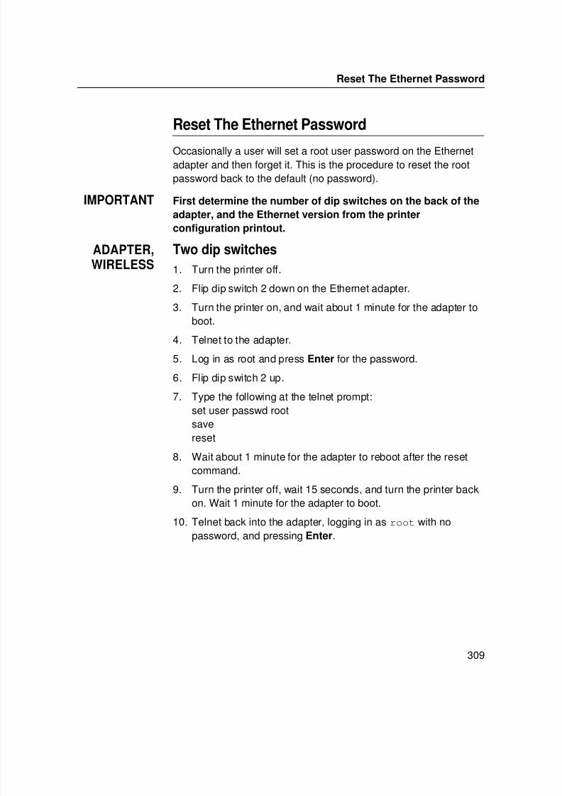
7/23/2019 54458302 IBM 6400
http://slidepdf.com/reader/full/54458302-ibm-6400 311/349
Reset The Ethernet Password
309
Reset The Ethernet Password
Occasionally a user will set a root user password on the Ethernetadapter and then forget it. This is the procedure to reset the rootpassword back to the default (no password).
IMPORTANT First determine the number of dip switches on the back of the
adapter, and the Ethernet version from the printer
configuration printout.
ADAPTER,WIRELESS
Two dip switches
1. Turn the printer off.
2. Flip dip switch 2 down on the Ethernet adapter.
3. Turn the printer on, and wait about 1 minute for the adapter toboot.
4. Telnet to the adapter.
5. Log in as root and press Enter for the password.
6. Flip dip switch 2 up.
7. Type the following at the telnet prompt:set user passwd rootsavereset
8. Wait about 1 minute for the adapter to reboot after the resetcommand.
9. Turn the printer off, wait 15 seconds, and turn the printer backon. Wait 1 minute for the adapter to boot.
10. Telnet back into the adapter, logging in as root with nopassword, and pressing Enter.
7/23/2019 54458302 IBM 6400
http://slidepdf.com/reader/full/54458302-ibm-6400 312/349
Chapter 17 Ethernet Interface Security
310
TCP Access Lists
Within TCP/IP environments, the Ethernet Interface can restricthost access to destinations/queues and remote command (e.g.,rsh, rcmd, remsh, and telnet) execution services. This is done usingan access list similar in function to the Unix .rhosts file.
NOTE: Access list settings are not configurable through the HTMLforms provided with the Ethernet Interface.
To view the current access list on the print server:
1. Start a Telnet session with the Ethernet Interface.
Syntax:telnet EthernetInterfaceIPaddress
2. Log in as root and press ENTER at the password promptsince there is no password by default (or your password foryour home set).
3. List the current access list.
Syntax:
List tcpip
If the list is empty, all hosts have access to the EthernetInterface services. If there are entries in the list, only thosehosts specified have access to printing and remote commandexecution.
To add and delete access list entries, the commands are:
Syntax:
store tcpip tcp access add|del hostIPaddress|networkaddress
reset
where hostIPaddress is the IP address of a TCP/IP host onyour network and networkaddress is the address of a subnet onyour network.
7/23/2019 54458302 IBM 6400
http://slidepdf.com/reader/full/54458302-ibm-6400 313/349
Printer And Print Job Monitoring
311
Example:
store tcpip tcp access add 192.75.11.25store tcpip tcp access add 192.75.12.0
store tcpip tcp access del 192.75.11.25
reset
NOTE: Although the maximum number of entries in the access listis 10, each entry can refer to a network rather than aspecific host. This allows all hosts on that specified networkand any individual hosts specified in the list to have access.
Printer Monitoring And LoggingThe Ethernet Interface allows you to monitor printer status and loginformation through its built-in HTML forms, command set, andlogpaths.
Printer And Print Job Monitoring
To view the current status of an I/O port on the Ethernet Interface,two methods are available:
• select the desired I/O port on the “Status” HTML form(i.e., http://EthernetInterfaceIPaddress/indexStatus.html; e.g., http://192.75.11.9/indexStatus.html) that comes with the Ethernet Interface.
• enter the lpstat command directly on the print server oncelogged in as guest or root.
In each case, you are given a description of each I/O port statusand a list of queued jobs. Table 13 describes some of the commonterms you may encounter.
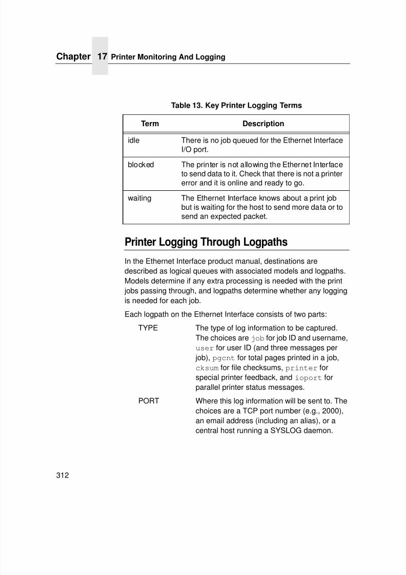
7/23/2019 54458302 IBM 6400
http://slidepdf.com/reader/full/54458302-ibm-6400 314/349
Chapter 17 Printer Monitoring And Logging
312
Printer Logging Through Logpaths
In the Ethernet Interface product manual, destinations aredescribed as logical queues with associated models and logpaths.Models determine if any extra processing is needed with the print
jobs passing through, and logpaths determine whether any logging
is needed for each job.Each logpath on the Ethernet Interface consists of two parts:
TYPE The type of log information to be captured.The choices are job for job ID and username,user for user ID (and three messages per
job), pgcnt for total pages printed in a job,cksum for file checksums, printer forspecial printer feedback, and ioport forparallel printer status messages.
PORT Where this log information will be sent to. Thechoices are a TCP port number (e.g., 2000),an email address (including an alias), or acentral host running a SYSLOG daemon.
Table 13. Key Printer Logging Terms
Term Description
idle There is no job queued for the Ethernet InterfaceI/O port.
blocked The printer is not allowing the Ethernet Interfaceto send data to it. Check that there is not a printererror and it is online and ready to go.
waiting The Ethernet Interface knows about a print jobbut is waiting for the host to send more data or tosend an expected packet.
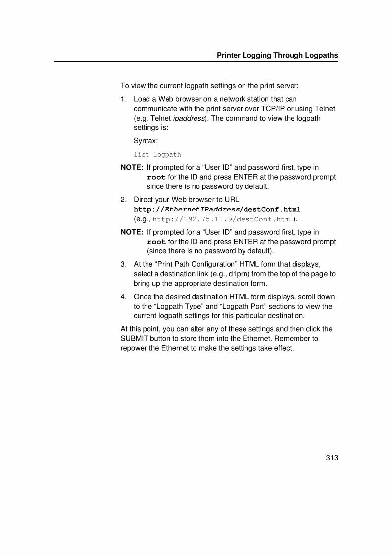
7/23/2019 54458302 IBM 6400
http://slidepdf.com/reader/full/54458302-ibm-6400 315/349
Printer Logging Through Logpaths
313
To view the current logpath settings on the print server:
1. Load a Web browser on a network station that cancommunicate with the print server over TCP/IP or using Telnet(e.g. Telnet ipaddress ). The command to view the logpathsettings is:
Syntax:
list logpath
NOTE: If prompted for a “User ID” and password first, type inroot for the ID and press ENTER at the password promptsince there is no password by default.
2. Direct your Web browser to URLhttp://EthernetIPaddress/destConf.html
(e.g., http://192.75.11.9/destConf.html).
NOTE: If prompted for a “User ID” and password first, type inroot for the ID and press ENTER at the password prompt(since there is no password by default).
3. At the “Print Path Configuration” HTML form that displays,select a destination link (e.g., d1prn) from the top of the page tobring up the appropriate destination form.
4. Once the desired destination HTML form displays, scroll downto the “Logpath Type” and “Logpath Port” sections to view thecurrent logpath settings for this particular destination.
At this point, you can alter any of these settings and then click theSUBMIT button to store them into the Ethernet. Remember torepower the Ethernet to make the settings take effect.
7/23/2019 54458302 IBM 6400
http://slidepdf.com/reader/full/54458302-ibm-6400 316/349
Chapter 17 Ethernet Interface Naming Schemes
314
Ethernet Interface Naming Schemes
A single I/O Port destination can be configured with a variety ofmodel and logpath combinations. For instance, once you set theparameters for m1 and l1, you can assign the model and logpath tomore than one I/O port destination such as d1prn, d2prn, andd8prn. You may now use the same set of model and logpathparameters more than once without having to redefine thoseparameters each time for another I/O Port destination.

7/23/2019 54458302 IBM 6400
http://slidepdf.com/reader/full/54458302-ibm-6400 317/349
315
Notices
Energy Star
The Environmental Protection Agency ENERGY STAR®
Computersprogram is a partnership effort with manufacturers of dataprocessing equipment to promote the introduction of energy-efficient personal computers, monitors, printers, fax machines, andcopiers to help reduce air pollution and global warming caused byelectricity generation.
IBM Printing Systems Company participates in this program byintroducing printers that reduce power consumption when they arenot being used. As an ENERGY STAR®
Partner, IBM PrintingSystems Company has determined that this product meets theENERGY STAR
®
guidelines for energy efficiency.
NOTE: The ENERGY STAR®
emblem does not represent EPAendorsement of any product or service.
7/23/2019 54458302 IBM 6400
http://slidepdf.com/reader/full/54458302-ibm-6400 318/349
Notices
316
Notices
This information was developed for products and services offeredin the U.S.A.
IBM may not offer the products, services, or features discussed inthis document in other countries. Consult your IBM representativefor information on the products and services currently available inyour area. Any reference to an IBM product, program, or service isnot intended to state or imply that only that IBM product, program,or service may be used. Any functionally equivalent product,program, or service that does not infringe any IBM intellectualproperty rights may be used instead. However, it is the user’sresponsibility to evaluate and verify the operation of any non-IBMproduct, program, or service.
IBM may have patents or pending patent applications coveringsubject matter described in this document. The furnishing of thisdocument does not give you any license to these patents. You cansend license inquires, in writing, to:
IBM Director of LicensingIBM Corporation
North Castle DriveArmonk, NY 10504-1785 U.S.A.
The following paragraph does not apply to the United
Kingdom or any other country where such provisions are
inconsistent with local law:
INTERNATIONAL BUSINESS MACHINES CORPORATIONPROVIDES THIS PUBLICATION “AS IS” WITHOUT WARRANTYOF ANY KIND, EITHER EXPRESS OR IMPLIED, INCLUDING,BUT NOT LIMITED TO, THE IMPLIED WARRANTIES OF NON-
INFRINGEMENT, MERCHANTABILITY OR FITNESS FOR APARTICULAR PURPOSE. Some states do not allow disclaimer ofexpress or implied warranties in certain transactions, therefore, thisstatement may not apply to you.

7/23/2019 54458302 IBM 6400
http://slidepdf.com/reader/full/54458302-ibm-6400 319/349
317
This information could include technical inaccuracies or
typographical errors. Changes are periodically made to theinformation herein; these changes will be incorporated in neweditions of the publication. IBM may make improvements and/orchanges in the product(s) described in this publication at any timewithout notice.
Any references in this information to non-IBM Web sites areprovided for convenience only and do not in any manner serve asan endorsement of those Web sites. The materials at those Websites are not part of the materials for this IBM product and use ofthose Web sites is at your own risk.
IBM may use or distribute any of the information you supply in anyway it believes appropriate without incurring any obligation to you.
Any performance data contained herein was determined in acontrolled environment. Therefore, the results obtained in otheroperating environments may vary significantly. Somemeasurements may have been made on development-levelsystems and there is no guarantee that these measurements will bethe same on generally available systems. Furthermore, somemeasurement may have been estimated through extrapolation.
Actual results may vary. Users of this document should verify theapplicable data for their specific environment.
Information concerning non-IBM products was obtained from thesuppliers of those products, their published announcements orother publicly available sources. IBM has not tested those productsand cannot confirm the accuracy of performance, compatibility orany other claims related to non-IBM products. Questions on thecapabilities of non-IBM products should be addressed to thesuppliers of those products.
This information contains examples of data and reports used in
daily business operations. To illustrate them as completely aspossibly, the examples include the names of individuals,companies, brands, and products. All of these names are fictitiousand any similarity to the names and addresses used by an actualbusiness enterprise is entirely coincidental.
7/23/2019 54458302 IBM 6400
http://slidepdf.com/reader/full/54458302-ibm-6400 320/349
Notices
318
If you are viewing this information softcopy, the photographs and
color illustrations may not appear.For online versions of this book, we authorize you to:
• Copy, modify, and print the documentation contained on themedia, for use within your enterprise, provided you reproducethe copyright notice, all warning statements, and other requiredstatements on each copy or partial copy.
• Transfer the original unaltered copy of the documentation whenyou transfer the related IBM product (which may be eithermachines you own, or programs, if the program’s license terms
permit a transfer). You must, at the same time, destroy all othercopies of the documentation.
You are responsible for payment of any taxes, including personalproperty taxes, resulting from this authorization.
Your failure to comply with the terms above terminates thisauthorization. Upon termination, you must destroy your machinereadable documentation.
7/23/2019 54458302 IBM 6400
http://slidepdf.com/reader/full/54458302-ibm-6400 321/349
319
Trademarks
The following terms, used in this publication, are trademarks of theIBM corporation in the United States or other countries or both:
AFCCU; iSeriesAFP Micro ChannelAdvanced Function Presentation z/OSAIX ® System/370AIX/6000 S/370AS/400 ® OS/2 ®
BCOCA Personal System/2 ®
Bar Code Object Content Architecture Print Services FacilityESCON ® pSeriesES/3090 PSFES/4381 PS/2 ®
ES/9000 RISC System/6000 ®
ES/9370 XGAIBM ® zSeries ®
InfoprintIPDS
C-bus is a trademark of Collary, Inc. in the United States, othercountries, or both.
Java and all Java-based trademarks and logos are trademarks orregistered trademarks of Sun Microsystems, Inc. in the UnitedStates, other countries, or both.
Microsoft, Windows, Windows NT, and Windows logo aretrademarks of Microsoft Corporation in the United States, othercountries, or both.
PC Direct is a trademark of Ziff Communications Company in the
United States, other countries, or both and is used by IBMCorporation under license.
ActionMedia, LANDesk, MMX, Pentium and ProShare aretrademarks of Intel Corporation in the United States, othercountries, or both. (For a complete list of Intel trademarks, seewww.intel.com/tradmarx.htm.)

7/23/2019 54458302 IBM 6400
http://slidepdf.com/reader/full/54458302-ibm-6400 322/349
Product Recycling and Disposal
320
Unix is a registered trademark of The Open Group in the United
States and other countries.SET and SET Logo are trademarks owned by SET SecureElectronic Transaction LLC. (For further information, seewww.setco.org/aboutmark.html.)
zSeries is a trademark of IBM.
Other company, product, or service names may be the trademarksor service marks of others.
Product Recycling and DisposalThis unit may have lead-containing materials – such as circuitboards and connectors – that require special handling. Before thisunit is disposed of, these materials must be removed and recycledor discarded according to applicable regulations. This bookcontains specific information on batteries and refrigerant whereapplicable.
This product may contain a sealed, lead-acid battery; lithiumbattery; nickel-metal-hydride battery; or nickel-cadium battery.
Batteries of these types must be recycled or disposed of properly.Recycling facilities may not be available in your area.
In the United States, IBM has established a collection process forreuse, recycling, or proper disposal of used batteries and batterpacks from IBM equipment. For information on proper disposal ofthe batteries in this product, please contact IBM at 1-800-426-4333.
For information on disposal of batteries outside the United States,contact your local waste disposal facility.
7/23/2019 54458302 IBM 6400
http://slidepdf.com/reader/full/54458302-ibm-6400 323/349
321
Communication Statements
Federal Communications Commission (FCC)Statement
This equipment has been tested and found to comply with the limitsfor a Class A digital device, pursuant to Part 15 of the FCC Rules.These limits are designed to provide reasonable protection againstharmful interference when the equipment is operated in acommercial environment. This equipment generates, uses, and canradiate radio frequency energy and, if not installed and used in
accordance with the instructions, may cause harmful interference toradio communications. Operation of this equipment in a residentialarea is likely to cause harmful interference in which case the userwill be required to correct the interference at his own expense.
Properly shielded and grounded cables and connectors must beused in order to meet FCC emission limits. Proper cables andconnectors are available from IBM authorized dealers. IBM is notresponsible for any radio or television interference caused by usingother than recommended cables and connectors or byunauthorized changes or modifications to this equipment.Unauthorized changes or modifications could void the user’sauthority to operate the equipment.
This device complies with Part 15 of the FCC Rules. Operation issubject to the following two conditions: (1) this device may notcause harmful interference, and (2) this device must accept anyinterference received, including interference that may causeundesired operation.

7/23/2019 54458302 IBM 6400
http://slidepdf.com/reader/full/54458302-ibm-6400 324/349
Communication Statements
322
European Union (EU) Conformity Statement
This product is in conformity with the protection requirements of ECCouncil Directive 89/336/EEC on the approximation of the laws ofthe Member States relating to electromagnetic compatibility.
IBM cannot accept responsibility for any failure to satisfy theprotection requirements resulting from a non-recommendedmodification of the product, including the fitting of non-IBM optioncards.
This product has been tested and found to comply with the limits forClass A Information Technology Equipment according to European
standard EN 55022. The limits for Class A equipment were derivedfor commercial and industrial environments to provide reasonableprotection against interference with licensed communicationdevices.
Properly shielded and grounded cables and connectors must beused in order to reduce the potential for causing interference toradio and TV communications and to other electrical or electronicequipment. Such cables and connectors are available from IBMauthorized dealers. IBM cannot accept responsibility for anyinterference caused by using other than recommended cables andconnectors.
Industry Canada Compliance Statement
This Class A digital apparatus complies with Canadian ICES-003.
Cet appareil numérique de la classe A conform á la norme NMB-003 du Canada.
This is a Class A product. In a domestic environment this product may cause radiointerference in which case the user may be required to take adequate measures.
WARNING

7/23/2019 54458302 IBM 6400
http://slidepdf.com/reader/full/54458302-ibm-6400 325/349
323
Statement of CISPR 22 Edition 2 Compliance
Attention: This is a Class A Product. In a domestic environmentthis product may cause radio interference in which case the usermay be required to take adequate measures.
Japanese VCCI Class A
Japan JEITA Statement
533

7/23/2019 54458302 IBM 6400
http://slidepdf.com/reader/full/54458302-ibm-6400 326/349
Communication Statements
324
Communication Statements (Taiwan)
Warning: This is a Class A product. In a domestic environment thisproduct may cause radio interference in which case the user will berequired to take adequate measures.
Australia/New Zealand
Attention: This is a Class A Product. In a domestic environmentthis product may cause radio interference in which case the usermay be required to take adequate measures.
Korea

7/23/2019 54458302 IBM 6400
http://slidepdf.com/reader/full/54458302-ibm-6400 327/349
325
China
Declaration: This is a Case A Product. In a domestic environmentthis product may cause radio interference in which case the usermay be required to take practical actions.
German Conformity StatementZulassungsbescheinigung Gesetz über die
elektromagnetische Verträglichkeit von Geraten (EMVG) vom
30. August 1995
Dieses Gerät ist berechtigt in Übereinstimmung mit dem deutschendas EG-Konformitätszeichen - CE - zu führen. Verantwortlich fürdie Konformitätserklärung nach Paragraph 5 des EMVG ist die IBM
Deutschland Informationssysteme GmbH, 70548 Stuttgart.
Informationen in Hinsicht EMVG Paragraph 3 Abs. (2) 2:
Das Gerät erfüllt die Schutzanforderungen nach EN 55022 KlasseA und EN 50024.
EN 55022 Klasse A Gerdte müssen mit folgendem Warnhinweisversehen werden: Warnung: dies ist eine Einrichtung der Klasse A.Diese Einrichtung kann im Wohnbereich Funkstörungenöerursachen; in diesem Fall kann vom Betreiber verlangt werden,angemessene Maßnahmen durchzuführen und dafür
aufzukommen.

7/23/2019 54458302 IBM 6400
http://slidepdf.com/reader/full/54458302-ibm-6400 328/349
Communication Statements
326
EN 55024 Hinweis:
Wird dieses Gerät in einer industriellen Umgebung betrieben (wiein EN 55024 festgelegt), dann kann es dabei eventuell gestörtwerden. In solch einem Fall ist der Abstand bzw. die Abschirmungzu der industriellen Störquelle zu öergrvßern.
Anmerkung:Um die Einhaltung des EMVG sicherzustellen sind die Geräte, wiein den Handbüchern angegeben, zu installieren und zu betreiben.
7/23/2019 54458302 IBM 6400
http://slidepdf.com/reader/full/54458302-ibm-6400 329/349
327
Glossary
ARP Address Resolution Protocol. Associates aselected IP address with a network deviceEthernet address.
bps Bits per second.
Centronics Parallel port interface standard found onmost printers.
daemon A continuously running process thathandles system-wide functions like printspooling.
default router Local device that forwards any IP packetsdestined for another subnet.
destination Logical print queue on the Ethernet towhich hosts send their print jobs. There
are eight destinations by default.DHCP Dynamic Host Configuration Protocol.
Allows a network device to discover its IPaddress dynamically upon bootup. The IPaddress does not need to be stored withinthe device itself permanently.
Download Mode Refers to the condition of the Ethernetwhen in a startup condition, downloadingconfiguration information.
DNS Domain Name Server. Host providingresponses to queries for a given hostname IP address.
EEPROM Electrically Erasable/Programmable Read-Only Memory.
7/23/2019 54458302 IBM 6400
http://slidepdf.com/reader/full/54458302-ibm-6400 330/349
328
factory defaults Settings shipped with the Ethernet.
Factory Settings S2 jumper position stating all factorydefault settings are to be used while theEthernet is up and running.
Firmware Panic Unrecoverable errors detected by theEthernet firmware force the Print Serverinto Firmware Panic mode. Manually resetthe Ethernet to resume operation.
Flash Stores firmware code and configurablesettings. Allows for upgrades without
replacing hardware inside the Ethernet.FTP File Transfer Protocol. Used for
transferring files from one TCP/IP host toanother and used in the upgrade process.
gateway A hardware device that translates databetween two incompatible networks.
gateway address The IP address of a gateway.
Hardware Exception Bus errors, address errors, and illegalinstructions force the Ethernet into this
non-operational mode.
HTML HyperText Markup Language. Formatused for documents viewable on the WorldWide Web.
ifnum Interface Number. Represents the networkinterface. With an Ethernet, this will alwaysbe “1.”
interface script Unix host filter file that processes the print job before it is sent over the network to the
Ethernet.
I/O port Port for attaching peripherals to. TheEthernet provides four: PRN1, PRN2,COM1, COM2.
7/23/2019 54458302 IBM 6400
http://slidepdf.com/reader/full/54458302-ibm-6400 331/349
329
IP Address The Internet Protocol Address. A numeric
address such as 123.45.61.23 whichidentifies a printer or server in a LAN orWAN.
LAN Local Area Network.
LED Light Emitting Diode. The printer has anLED display which shows the status of theprinter to the operator.
logpath Determines the type of print job and printerlogging needed per job. One logpath is
associated with every destination.LPD/LPR Line Printer Daemon. The most common
TCP/IP remote printing protocol thatcrosses all hardware utilizing IP.
MAC Machine Address Code.
MIB Management Information Base. A set ofvariables (database) managed by anSNMP manager application.
model Defines how a print job should be
processed (e.g., banner pages added,ASCII to PostScript conversion) as itpasses through the Ethernet. One model isassociated with every destination.
NetBIOS Network Basic Input Output System.Common interface among PC networks.
Monitor Mode Refers to the condition of the Ethernet withno configuration or IP address loaded.
npsh Extensive built-in command shell within
the Ethernet.
PDF Portable Document Format. Encodesdifferent types of documents enablingthem to be read across multiple platforms.
ping Standard command to test a TCP/IPconnection. (e.g., ping 192.75.11.9)
7/23/2019 54458302 IBM 6400
http://slidepdf.com/reader/full/54458302-ibm-6400 332/349
330
print path Three-stage path a print job takes when it
is sent from a host to a printer through theEthernet.
protocol A set of rules or conventions governing theexchange of information betweencomputer systems or between a printerand a host computer. For computerprinters, a protocol is the codingconvention used to convey and print data.A printer protocol includes codes forprinting text and graphics, as well as codes
instructing the printer to perform specialoperations and machine-to-machinecommunication codes.
PSERVER Print Server. A Novell print method wherethe Ethernet continuously polls the Novellfile server print queue looking for print
jobs.
RAM Random Access Memory. Volatile memorywithin the Ethernet that contains current/
working settings. Settings are lost once thepower is removed.
RARP Reverse Address Resolution Protocol.Allows a network device to discover its IPaddress dynamically upon bootup. The IPaddress does not need to be stored withinthe device itself permanently.
ROM Read-Only Memory.
router A device that forwards IP packets to their
destination. Also called a gateway.RPRINTER Remote Printer. A Novell print method
where the Ethernet waits for jobs to besent to it from a defined PSERVER.
7/23/2019 54458302 IBM 6400
http://slidepdf.com/reader/full/54458302-ibm-6400 333/349
331
SNMP Simple Network Management Protocol. A
standard protocol used to monitor networkdevices called “SNMP agents.”
socket TCP connection between two hostsconsisting of a source and destination TCPport number at each end.
subnet mask A binary value used to divide IP networksinto smaller sub-networks or subnets. Thismask is used to help determine whether IPpackets need to be forwarded to othersubnets.
TCP/IP Transmission Control Protocol/InternetProtocol. Suite of protocols that act as thebase protocol for the Internet.
TCP port A logical connection point in the softwareof a TCP host or device. When two IPdevices talk, they establish a socket whichconsists of a source and destination TCPport number on both ends.
telnet Command and protocol to establish aterminal connection between two hosts onan IP network.
UTP Unshielded Twisted Pair. A cable used fortelephone and computer-to-computerconnections.
WAN Wide Area Network.

7/23/2019 54458302 IBM 6400
http://slidepdf.com/reader/full/54458302-ibm-6400 334/349
332
7/23/2019 54458302 IBM 6400
http://slidepdf.com/reader/full/54458302-ibm-6400 335/349
333
IndexSymbols
*LAN 3812 SNMP
configuration instructions, 259
*LAN 3812 SNMP Device Description, 259
? command, 276
Numerics10/100Base-T
indicators, 19
Novell Ethernet Interface
configuration, 144
Novell host configuration, 156
RPRINTER/NPRINTER setup,
troubleshooting, 170
speed setting, 24
troubleshoot printing, 172
troubleshooting, 167
Wireless Network Indicator, 21
AAccess lists, TCP, 310
Access methods, npsh, 275
Activation Timer (ACTTMR), 260
Add preferred file server, 145
Additional information, 266
ADDTCPIFC, configuring with, 177ADDTCPRTE, router definition, 179
Administration
configuration, 70
Contact, 71
Description, 71
DNS Server, 72
Email, 72
Location, 71
Name, 71
Passwords, 72
Printer Serial Number, 71
SMTP Server, 72
Syslog, 71
System information, 70
AFP file printing, 191
Agent model, printer monitoring, 267
AIX
NetView/6000, monitoring, 271
printing, 117
AIX 4.x setup, 118Alert groups, 66
Alternatives, configuration, 42
APR, Ethernet Interface, 108
ASCII
configuring iSeries, 177
setting up for printing, 180
ASCII Troubleshooting, iSeries, 186
Auto Connect, TN5250/3270, 62
Auto reset mode, 19Automatic remote output queue,
iSeries, 182
7/23/2019 54458302 IBM 6400
http://slidepdf.com/reader/full/54458302-ibm-6400 336/349
Index
334
BBindery PSERVER setup
NetWare 3.x, 160
NetWare 4.x, 160
NetWare 5.x, 160
Bindery setup
change Ethernet Interface frame type, 152
change Ethernet Interface mode, 153change Ethernet Interface name, 150
password security, 147
polling time, 149
preferred file server, 144
BOOTP, Unix, 111
Browse Ethernet Interface,
troubleshooting, 100
CChange destination names, Ethernet
Interface, 80
Change Ethernet Interface frame type
Bindery setup, 152
NDS setup, 152
Change Ethernet Interface mode
Bindery setup, 153
NDS setup, 153
Change Ethernet Interface nameBindery setup, 150
NDS setup, 150
Coax Printer Support FMD, 233
Command
?, 276
complete list, 276
getting help, 276
Command list
List commands, 254
store commands, 253
TN5250, 253TN5250/3270 Auto Connect
Command, 254
Command prefixes, 276
npsh, 275
Command Shell, 275
ways to access, 39
Commands
list, 299
miscellaneous, 303set, 287
store, 277
Communcation routers, Windows, 78
Configuration
Administration, 70
alternatives, 42
Encryption Key, 36
Equivalent Wireless Ethernet Interface, 37
front panel, 29IP Address, 33
Log Path, 57
Network, 46
7/23/2019 54458302 IBM 6400
http://slidepdf.com/reader/full/54458302-ibm-6400 337/349
Index
335
Print Model, 54
Print Path, 50PSF for IPDS on V3R7 or V4RI, 196
PSF for IPDS on V4R2 and above, 202
SNMP, 63
System, 73
TN5250/3270, 59
wireless Ethernet Interface, 33
Wireless Parameter, 34
Configuration checklist, MVS, 216
Configuration example, 263
Configuration instructions
*LAN 3812 SNMP, 259
Activation Timer (ACTTMR), 260
Configuration example, 263
Device Class (DEVCLS), 259
Device Model (MODEL), 259
Device Type (Type), Device Type
(Type), 259Font (FONT) = 011, 260
Form Feed (FORMFEED), 260
Host Print Transform
(TRANSFORM), 261
Inactivity Timer (INACTTMR), 261
LAN Attachment (LANATTACH), 259
Manufacturer Type and Model
(MFRTYPMDL), 261
Port number (PORT), 260Printer Error Message
(PRTERRMSG), 260
Remote Location
(RMTLOCNAME), 261
System Driver Program
(SYSDRVPGM), 262User-Defined Options
(USRDFNOPT), 262
Workstation Customizing Object
(WSCST), 262
Configuration menu, Ethernet Interface, 44
Configuration Screens, TN3270E, 247
Configuration tools, 28
Configuring for a *LAN 3812 SNMP Device
Description, 259
Connecting to the network, 27
CRTLINETH, line descriptions, 175
DDefine LPR printer, error, 99
Destination settings, Print Path, 50
Destinations
Ethernet Interface, 17
models, 17Device Class (DEVCLS), 259
Device Description, *LAN 3812 SNMP, 259
Device Description, TN5250/3270, 61
Device Model (MODEL), 259
Device Type, TN5250/3270, 62
Direct socket printing, 117
Document conventions, 25
EEncryption Key Configuration, 36
Equivalent Wireless Ethernet Interface
Configuration, 37
Errors, defining LPR printer, 99
7/23/2019 54458302 IBM 6400
http://slidepdf.com/reader/full/54458302-ibm-6400 338/349
Index
336
Ethernet Interface, 13
cannot be found, 98
cannot be found on network,
troubleshooting, 119
change destination names, 80
configuration (10/100Base-T), Novell, 144
configuration menu, 44
configuration, Windows, 76destinations, 17
guest user, 307
HTML structure, 39
installation, 27
naming schemes, 314
NDS content, NDS setup, 154
passwords, 307
preferred NDS tree, NDS setup, 155
queues, 17root user, 307
security, 307
Set NDS content, 154
Set preferred NDS tree, 155
special features, 14
users, 307
verification, 38
FFont (FONT) = 011, 260
Font Identifier, TN5250, 257
Form Feed (FORMFEED), 260
Front panel, configuration, 29
FTP printing, 115
GGetting Help command, 276
Getting started, NIC with AS400 running
TN5250, 254
Guest user, Ethernet Interface, 307
H
Help command, getting, 276Home page, URL, 39
Host configuration
Novell, 128
Unix, 113
Host IP, TN5250/3270, 60
Host Print Transform (TRANSFORM), 261
Host setup
Windows 2000, 82
Windows 9x, 96Windows Me, 96
Windows NT 3.51, 95
Windows NT 4.0, 90
Windows XP, 82
HTML
forms, 39
forms, Novell, 127
method, print server setup, 148
structure, Ethernet Interface, 39HTTP, troubleshooting, 103
7/23/2019 54458302 IBM 6400
http://slidepdf.com/reader/full/54458302-ibm-6400 339/349
Index
337
II/O Port, status, 74
IBM Network Printer Manager (NPM), 273
IBM Printing Systems, 74
Inactivity Timer (INACTTMR), 261
Indicators, 10/100Base-T, 19
Installation, Ethernet Interface, 27
IP Address Configuration, 33
IPDS
configuration checklist, iSeries, 192
configuration, verify on iSeries, 209
file printing, 191
printer, configuring on iSeries, 191
iSeries
ASCII HTTP problem, 189
ASCII troubleshooting, 186
automatic remote output queue, 182
configuring as an IPDS printer, 191
configuring for ASCII, 177configuring for printing, 180
CRTLINETH, 175
hostname, 179
IPDS configuration checklist, 192
local domain, 179
network sharing, 211
printer sharing parameters, 211
printing AFP files, 191
printing IPDS files, 191printing SCS files, 191
remote printer queue name, 180
TCP/IP access problem, 187
TCP/IP host table entry, 179
troubleshooting, 213
verify IPDS configuration, 209verify printing, 185
iSeries troubleshooting
cannot PING the printer, 213
clipped data, 214
PSF terminates when initialized, 213
spooled files disappear without
printing, 214
spooled print file remains in PND
status, 214
JJob formatting, TN5250, 255
LLAN Attachment (LANATTACH), 259
Line descriptions, CRTLINETH, 175
List commands, 299
TN5250, 254Log Path
configuration, 57
Logpath Port, 58
Logpath Type, 57
Name, 57
Logging, printer, 311
Logical printer architecture, 15
Logpaths, printer logging, 312
LPR/LPD Host setup, 114
7/23/2019 54458302 IBM 6400
http://slidepdf.com/reader/full/54458302-ibm-6400 340/349
Index
338
MManager model, printer monitoring, 267
Manual (Telnet) method, print server setup, 148
Manual LPR/LPD Host setup, 114
Manual system, V Host setup, 113
Manufacturer Type and Model
(MFRTYMDL), 261
Message Queue Library, TN5250/3270, 61Message Queue Name, TN5250/3270, 61
MIB, 268
Microsoft TCP/IP printing, 104
Miscellaneous commands, 303
Mode
auto reset, 19
run, 19
Mode, TN5250/3270, 60
Models, 17setting a formfeed, 122
setting onlcr, 121
Monitoring
print job, 311
printer, 311
MVS
configuration checklist, 216
define printer to JES, 222
JES spool printer sharing, 228
port switching printer sharing, 230
printer connection, 221
requirements, 215
NNaming schemes, Ethernet Interface, 314
NDPS configuration, NetWare 4.11 and
above, 164
NDS PSERVER setup
NetWare 4.x, 157
NetWare 5.x, 157
NDS setupchange Ethernet Interface frame type, 152
change Ethernet Interface mode, 153
change Ethernet Interface name, 150
Ethernet Interface NDS content, 154
Ethernet Interface preferred NDS tree, 155
password security, 147
polling time, 149
preferred file server, 144
NetBIOS TCP/IP, Windows Network, 47NetWare 3.x
Bindery PSERVER setup, 160
no PSERVER connection, 140
password security, 147
polling time, 149
reference a Bindery queue, 160
RPRINTER/NPRINTER setup, 161
NetWare 4.11 and above, NDPS
configuration, 164
NetWare 4.x
Bindery PSERVER setup, 160
NDS PSERVER setup, 157
no PSERVER connection, 141
password security, 147
7/23/2019 54458302 IBM 6400
http://slidepdf.com/reader/full/54458302-ibm-6400 341/349
Index
339
polling time, 149
reference a Bindery queue, 160RPRINTER/NPRINTER setup, 161
NetWare 5.x
Bindery PSERVER setup, 160
NDS PSERVER setup, 157
no PSERVER connection, 141
password security, 147
polling time, 149
reference a Bindery queue, 160
RPRINTER/NPRINTER setup, 161
NetWare Version 3.x
Pserver setup, 128
RPrinter setup, 131
NetWare Version 4.x
PSERVER setup, 134
RPRINTER setup, 137
NetWare Version 5.x
PSERVER setup, 134RPRINTER setup, 137
Network
configuration, 46
connection, 27
Ethernet Interface cannot be found, 98
Novell, 48
sharing, iSeries, 211
status, 74
TCP/IP, 46Network Printer Manager (NPM), IBM, 273
NIC
reset password, 309running AS400 with TN5250, 254
No extra page, troubleshooting, 122
No form feed, troubleshooting, 122
Novell
environment, 125
Ethernet Interface configuration, 126
Ethernet Interface configuration
(10/100Base-T), 144
file server, 49
frametype, 48
Host configuration, 128
host configuration, 10/100Base-T, 156
HTML forms, 127
NDS, 49
Network, 48
Pserver, 49
Rprinter, 49service type, 49
troubleshooting, 139
Npsh
access methods, 275
command prefixes, 275
OOnlcr, 121
OS/2 TCP/IP, 270
7/23/2019 54458302 IBM 6400
http://slidepdf.com/reader/full/54458302-ibm-6400 342/349
Index
340
PPassword security
Bindery setup, 147
NDS setup, 147
NetWare 3.x, 147
NetWare 4.x, 147
NetWare 5.x, 147
Passwords, 72Ethernet Interface, 307
reset, 309
PMU, 270
Polling time
adjusting, 149
Bindery setup, 149
NDS setup, 149
NetWare 3.x, 149
NetWare 4.x, 149NetWare 5.x, 149
Port number (PORT), 260
Port, TN5250/3270, 61
Preferred file server
adding, 145
Bindery setup, 144
NDS setup, 144
removing, 146
Prefixes, command, 276
Print job monitoring, 311
Print Model
Banner Page, 55
configuration, 54
Filter, 55
Header String, 55
Model Type, 54
Name, 54
Printer Configuration, 56Trailer String, 55
Print Path
Back Channel, 50
Banner Page, 52
configuration, 50
destination settings, 50
Filter, 52
Header String, 52
Log Path Port, 53Log Path Type, 53
Model Type, 52
Name, 50
Printer Configuration, 53
Selected Log Path, 53
Selected Model, 51
Services, 51
Trailer String, 52
Print server setupHTML method, 148
manual (Telnet) method, 148
7/23/2019 54458302 IBM 6400
http://slidepdf.com/reader/full/54458302-ibm-6400 343/349
Index
341
Printer
errors, 100logging, 311
logging through logpaths, 312
monitoring, 311
sharing parameters, iSeries, 211
status screen, 41
varying, 265
Printer Error Message
(PRTERRMSG), 260
Printer Inventory Manager, TN3270E, 238
Printer management implementation, 267
Printer management utility (PMU), 270
Printer monitoring
Agent model, 267
Manager model, 267
MIB, 268
SNMP, 270
tools, 270Printing
AIX, 117
ASCII, 180
configuration, iSeries, 180
direct socket, 117
FTP, 115
troubleshooting, 120
verification, iSeries, 185
ProblemiSeries ASCII HTTP, 189
iSeries ASCII Web browser, 189
Problem areas, 265
Program materials, TN3270E, 234
PSERVER setup
NetWare Version 4.x, 134NetWare Version 5.x, 134
PSERVER setup (10/100Base-T),
troubleshooting, 167
Pserver setup, NetWare Version 3.x, 128
PSF for IPDS
on V3R7 or V4RI, configuring, 196
on V4R2 and above, configuring, 202
QQueues
Ethernet Interface, 17
models, 17
RRARP, Unix, 110
Reference a Bindery queue in NDS
NetWare 3.x, 160
NetWare 4.x, 160NetWare 5.x, 160
Remote shell, 42
Remove preferred file server, 146
Resource Name, TN5250/3270, 61
Root user, Ethernet Interface, 307
Routers, Unix, 112
RPRINTER setup
NetWare Version 4.x, 137
Netware Version 5.x, 137RPrinter setup, NetWare Version 3.x, 131
7/23/2019 54458302 IBM 6400
http://slidepdf.com/reader/full/54458302-ibm-6400 344/349
Index
342
RPRINTER/NPRINTER setup
NetWare 3.x, 161
NetWare 4.x, 161
NetWare 5.x, 161
Run mode, 19
SSCS file printing, 191
Security, Ethernet Interface, 307
Set commands, 287
Setup, AIX 4.x, 118
Shell, command, 275
SNMP, 270
Alert groups, 66
configuration, 63
Email alert posting, 64
manager alert posting, 63SNMP community name, 271
SNMP support, 259
Special features, Ethernet Interface, 14
Speed setting, 10/100Base-T, 24
Stair-stepped output, troubleshooting, 121
Start/Stop Auto Connect, TN5250/3270, 62
Status
I/O Port, 74
menu, 73Network, 74
Status screen, printer, 41
Store commands, 277
TN5250, 253
Syslog alert posting, 64
System configuration, 73
System Driver Program (SYSDRVPGM), 262
TTCP access lists, 310
TCP/IP
access, troubleshooting, 101
configuring iSeries for ASCII, 177
network, 46
TCP/IP access problem
iSeries, 187
Unix, 122
TCPIP Configuration, TN3270E, 237
Technical support, 98
Telnet, 42
Telnet commands, TN5250, 253TN3270E
Configuration Screens, 247
Printer Inventory Manager, 238
Programs materials, 234
TCPIP Configuration, 237
VTAM Definitions, 235
z/OS Configuration, 233
TN5250
command list, 253Font Identifier, 257
job formatting, 255
running AS400, 254
set up connection device via telenet, 252
set up print queue on iSeries, 251
7/23/2019 54458302 IBM 6400
http://slidepdf.com/reader/full/54458302-ibm-6400 345/349
Index
343
Telnet commands, 253
user supplied values, 253TN5250/3270
Auto Connect, 62
Auto Connect command, 254
configuration, 59
Device Description, 61
Device Type, 62
Host IP, 60
Message Queue Library, 61
Message Queue Name, 61
Mode, 60
Port, 61
Resource Name, 61
Start/Stop Auto Connect, 62
WSCST Library, 62
WSCST Name, 62
Tools, printer monitoring, 270
Troubleshooting(10/100Base-T) RPRINTER/
NPRINTER, 170
10/100Base-T, 167
10/100Base-T printing, 172
cannot browse Ethernet Interface on
Network, 100
defining LPR printer, 99
Ethernet Interface cannot be found, 98
Ethernet Interface cannot be found onNetwork, 119
HTML configuration forms, 99
HTTP, 103
iSeries, 213
NetWare 3.x, no PSERVER
connection, 140NetWare 4.x, no PSERVER
connection, 141
NetWare 5.x, no PSERVER
connection, 141
no extra page, 122
no form feed, 122
Novell, 139
printer errors, 100
printing, 120
PSERVER setup (10/100Base-T), 167
stair-stepped output, 121
TCP/IP access problem, 101
Unix, 119
Web browser, 103
Windows, 98
Windows 2000 Host setup, 103
Windows NT 4.0 Host setup, 103
UUnix
crossing routers, 112
environment, 107
Ethernet Interface configuration, 108
Host configuration, 113
manual system V Host setup, 113
TCP/IP access problem, 122
troubleshooting, 119
using APR, 108
using BOOTP, 111
using RARP, 110
7/23/2019 54458302 IBM 6400
http://slidepdf.com/reader/full/54458302-ibm-6400 346/349
Index
344
URL, home page, 39
User-Defined Options (USRDFNOPT), 262Users, Ethernet Interface, 307
Using ARP, Windows, 76
VV Host setup, manual system, 113
Varying on the Printer, 265
Verification, Ethernet Interface, 38
VTAM Definitions, TN3270E, 235
WWeb browser
problem, 189
troubleshooting, 103
Web server, overview, 43
Windows
communication routers, 78
configuration, 75
environment, description, 75
Ethernet Interface configuration, 76
mandatory configuration, 76
optional configuration, 76
troubleshooting, 98
using ARP, 76
Windows 2000
Host setup, 82
Host setup, troubleshooting, 103
Windows 9x, Host setup, 96
Windows Me, Host setup, 96
Windows Network (NetBIOS TCP/IP), 47
Windows NT 3.51, Host setup, 95
Windows NT 4.0
Host setup, 90Host setup, troubleshooting, 103
Windows XP
Host setup, 82
Wireless Ethernet Interface
Configuration, 33
Wireless Network Indicator, 21
Wireless Parameter Configuration, 34
Workstation Customizing Object
(WSCST), 262WSCST Library, TN5250/3270, 62
WSCST Name, TN5250/3270, 62
Zz/OS
communications control unit, 218
connectivity problems, 230
define printer to PSF, 223
printer sharing, 228printing IPDS, 217
TCP/IP profile, 218
verifying TCP/IP-attached printer, 227
z/OS Configuration, TN3270E, 233
7/23/2019 54458302 IBM 6400
http://slidepdf.com/reader/full/54458302-ibm-6400 347/349
Readers’ Comments — We’d Like to Hear from You
IBM 4400 Series Thermal Printer:Legacy Migration Utility
Publication No. G544-5796-00
Overall, how satisfied are you with the information in this book?
Very Satisfied Satisfied Neutral Dissatisfied Very
Dissatisfied
Overall satisfaction h h h h h
How satisfied are you that the information in this book is:
Very Satisfied Satisfied Neutral Dissatisfied Very
Dissatisfied
Accurate h h h h h
Complete h h h h h
Easy to find h h h h h
Easy to understand h h h h h
Well organized h h h h h
Applicable to your tasks h h h h h
Please tell us how we can improve this book:
Thank you for your responses. May we contact you? h Yes h No
When you send comments to IBM, you grant IBM a nonexclusive right to use or distribute your comments in any
way it believes appropriate without incurring any obligation to you.
Name Address
Company or Organization
Phone No.
IBM 6400i Ethernet Interface User’s Manual
S544-5830-02
7/23/2019 54458302 IBM 6400
http://slidepdf.com/reader/full/54458302-ibm-6400 348/349
346
Readers’ Comments — We’d Like to Hear from YouG544-5796-00
G544-5796-00
Cut or FoldAlong Line
Cut or FoldAlong Line
Fold and Tape Please do not staple Fold and Tape
Fold and Tape Please do not staple Fold and Tape
NO POSTAGENECESSARYIF MAILED IN THEUNITED STATES
BUSINESS REPLY MAILFIRST-CLASS MAIL PERMIT NO. 40 ARMONK, NEW YORK
POSTAGE WILL BE PAID BY ADDRESSEE
IBM Corporation
Information DevelopmentIBM Printing SystemsDepatment 583E Building 003GPO Box 1900Boulder, CO 80301-9817
_ _ _ _ _ _ _ _ _ _ _ _ _ _ _ _ _ _ _ _ _ _ _ _ _ _ _ _ _ _ _ _ _ _ _ _ _ _ _ _ _ _ _ _ _ _ _ _ _ _ _ _ _ _ _ _ _ _ _ _ _ _ _ _ _ _ _ _ _ _ _ _ _ _ _ _ _ _ _ _ _ _ _ _ _ _ _ _ _
_ _ _ _ _ _ _ _ _ _ _ _ _ _ _ _ _ _ _ _ _ _ _ _ _ _ _ _ _ _ _ _ _ _ _ _ _ _ _ _ _ _ _ _ _ _ _ _ _ _ _ _ _ _ _ _ _ _ _ _ _ _ _ _ _ _ _ _ _ _ _ _ _ _ _ _ _ _ _ _ _ _ _ _ _ _ _ _ _
_ _ _
_ _ _ _ _ _ _ _ _ _ _ _ _ _ _ _ _ _ _ _ _ _ _ _ _ _ _ _ _ _ _ _ _ _ _ _ _ _ _ _ _ _ _ _ _ _ _ _ _
_ _ _ _ _ _ _ _ _ _ _ _ _ _ _ _ _ _ _ _ _ _ _ _ _ _ _ _ _ _ _ _ _ _ _ _ _ _ _ _ _ _ _ _ _ _ _
S544-5830-02
IBM Corporation
Information Development
IBM Printing Systems
Department H7FE Building 004M
PO Box 1900
Boulder, CO 80301-9817
S544-5830-02

7/23/2019 54458302 IBM 6400
http://slidepdf.com/reader/full/54458302-ibm-6400 349/349