Embed Size (px)
Citation preview

2792-20M18™ Radio Charger Dec. 2013
54-49-0300REVISED BULLETIN
SERVICE PARTS LISTBULLETIN NO.
WIRING INSTRUCTION
DATE
CATALOG NO.
SPECIFY CATALOG NO. AND SERIAL NO. WHEN ORDERING PARTS
SERIALNUMBER
MILWAUKEE ELECTRIC TOOL CORPORATION13135 W. LISBON RD., BROOKFIELD, WI 53005
Drwg. 1
F69A SEE PAGE 4
FIG. PART NO. DESCRIPTION OF PART NO. REQ. 1 05-88-1735 M3 x 12mm Pan Hd. Hex (30) 2 05-88-1750 M3 x 16mm Pan Hd. Hex (20) 3 05-88-1741 M3 x 12mm Pan Hd. Phillips (14) 5 05-88-1745 M3 x 10mm Pan Hd. Washer Phillips (6) 6 05-88-1760 M3 x 25mm Pan Hd. Hex (2)
Left Handle
Speaker Grill
#1 (6x)
#3 (2x) #3 (4x each side)
Under Left and Right Handles. The Right and Left Handles must be removed to access the eight #3 screws
#2 (3x each side) on bottom of Left and Right Handles
#2 (9x each side) on side of Left and Right Handles
#2 (1x each side) on back of Left and Right Handles
Right Handle
#1 (1x each side) on bottom of Left and Right Handles
NOTE:The same series of screws that are used for the Left Handle are used on the Right Handle
#6(2x)
#1 (4x each side) on side of Left and Right Side Handles
#1 (4x) on the two top and two bottom holes of Rear Cabinet.
#3 (4x) on the Rear Cabinet. See back view detail at the left.
#1 (6x) on the bottom of Rear Cabinet.
#5 (6x) IMPORTANT: These 6 screws must be removed from the inside of the Rear Cabinet in order to remove the Left and Right Side Handles.
Rear Cabinet
Front Cabinet Left Side Handle
BO
TTO
M V
IEW
FRO
NT
VIEW
BA
CK
VIE
WSI
DE
VIEW
NOTE:All fasteners
indicated must beremoved to gain
access to the interiorof the unit and servicing of the
Charger andPCBA
Speaker Grill removed to show these screws
Screws behind Left & Right Handles(8x)
28
1112 30
#6(2x)
1(6x)
11
1(4x)
12
10
15
3 (4x) Chrome
17
18(3x)
13 19See detail belowfor wire ribboninformation
14
12
3(4x)
*
*
110 31
16
14
3(4x), 22(2x)
22(2x)
ATTENTIONOBSERVE PRECAUTIONS
FOR HANDLINGELECTROSTATIC
SENSITIVEDEVICES
FIG. PART NO. DESCRIPTION OF PART NO. REQ. 1 05-88-1735 M3 x 12mm Pan Hd. Hex (10) 3 05-88-1741 M3 x 12mm Pan Hd. Phillips Screw (8) 6 05-88-1760 M3 x 25mm Pan Hd. Hex (2) 10 --------------- Speaker Grill (1) 11 --------------- On-Off Dial (1) 12 --------------- Face Plate (1) 13 45-06-1075 Gasket (Door Seal) (1) 14 42-92-1700 Device Door Assembly (1) 15 22-68-0325 Backup Battery Door Assembly (1) 16 14-06-0150 Device Storage Assy. with AM Antenna (1) 17 22-09-0035 USB PCBA (1) 18 05-88-1765 M2.6 x 10mm Pan Hd. Phillips Screw (3) 19 22-09-0490 Main PCBA (1) 22 05-88-1770 M3 x 14mm Pan Hd. Washer Phillips (2) 28 12-20-2792 Service Nameplate (1) 30 14-46-0875 On-Off Dial with Face Plate (1) 31 43-40-0730 Speaker Grill with Screws (1)
For ease of removal of the devise door assembly #14, remove only one of the hinge pins by using a heavy thin wire (like an unbent paper clip) and push the pin outward. If necessary, use a needle nose pliers to grab the knurled end of the pin and remove.
NOTE:Hook the two tabs on top of Face Plate #12 into the two slots in the Front Cabinet and lower into place. Secure with four screws #1.
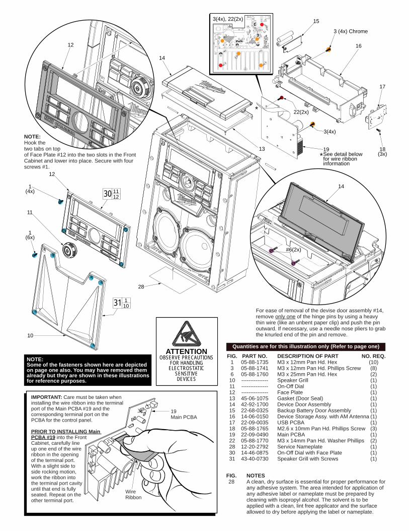
IMPORTANT: Care must be taken wheninstalling the wire ribbon into the terminal port of the Main PCBA #19 and the corresponding terminal port on the PCBA for the control panel.
PRIOR TO INSTALLING Main PCBA #19 into the Front Cabinet, carefully line up one end of the wire ribbon in the opening of the terminal port. With a slight side to side rocking motion, work the ribbon into the terminal port cavityuntil that end is fully seated. Repeat on theother terminal port.
19Main PCBA
WireRibbon
FIG. NOTES 28 A clean, dry surface is essential for proper performance for any adhesive system. The area intended for application of any adhesive label or nameplate must be prepared by cleaning with isopropyl alcohol. The solvent is to be applied with a clean, lint free applicator and the surface allowed to dry before applying the label or nameplate.
NOTE:Some of the fasteners shown here are depicted on page one also. You may have removed them already but they are shown in these illustrations for reference purposes.
Quantities are for this illustration only (Refer to page one)

ATTENTIONOBSERVE PRECAUTIONS
FOR HANDLINGELECTROSTATIC
SENSITIVEDEVICES
FIG. PART NO. DESCRIPTION OF PART NO. REQ. 1 05-88-1735 M3 x 12mm Pan Hd. Hex (8) 3 05-88-1741 M3 x 12mm Pan Hd. Phillips (6) 23 05-88-1775 M3 x 16mm Pan Hd. Washer Phillips (8) 24 --------------- FM Antenna (1) 25 --------------- M3 x 6mm Pan Hd. Hex (1) 26 31-15-2350 18V Bracket/Door Assembly (1) 27 14-38-0850 18V Charger Assembly (1) 27a --------------- Battery Terminal Connector Block (1) 32 42-09-0500 FM Antenna with Screw (1) 33 22-64-0985 Cord Set (Not Shown) (1) 34 42-44-0225 Auxilary Input Cable (Not Shown) (1)
EXAMPLE:Component Parts (Small #) Are Included When Ordering The Assembly (Large #).
000
3 (2x) in the back (Chrome)
1 (2x) in the back (Black Oxide)
3 (4x) 2x each side (Chrome)
23 (8x)
25 (1x)
24
26
27a
33
1 (6x)3
1
27a 27
1 (6x) on the bottom (Black Oxide)
NOTE: With the Front Cabinet separated from the Rear Cabinet, the fasteners that are indicated in this illustration must be removed from the Rear Cabinet in order to take out the Charger Assembly #27.
2425 32
Illustration shown without the top handle for clarity of wherescrew #25 is located. Top handle does not have to be removed.
SEE PAGE 4 FOR WIRINGINSTRUCTIONS
17 USB PCBA
19 Main PCBA
16 Device Storage Assembly
When removing the Device Storage Assembly #16 or the Main PCBA #19, the thin wires from the AM Antenna must be unsoldered from the Main PCBA. With the Device Storage Assembly and the Main PCBA installed back in the Front Cabinet, AM Antenna wires are to be resoldered to the PCBA atthe same locations.
Solder thin wires to Main PCBA at positions marked JP13 and JP14
16Device
StorageAssemblyIf replacing the
USB PCBA #17, wires from that assembly are routed through wire traps on the Device Storage Assy.#16. During the manufacturing process, those traps are melted over to secure leadwires and wire harnesses. To free the wires of the USB PCBA, use a small needle nose pliers or a knife blade to carefully remove the melted material. Secure the new USB PCBA onto the Device Storage Assembly with three screws and route the wires through the same traps. Secure the wires with hot glue.
17 USB PCBA
Traps
NOTE:Some of the fasteners shown here are depicted on page one also. You may have removed them already but they are shown in these illustrations for reference purposes.
Quantities are for this illustration only (Refer to page one)

Red wire from FM Antenna
Solder AM Antenna wires here
Red, black and white wires(contained in Grey insulating sleeve) from the USB PCBA
Wire Ribbon to Control Panel PCBA
4 wire harness (4 white wires)from ChargerAssembly
Red and black wires from USB PCBA
Multi-colored5 wire harness(black, red, orange, yellow and blue)from ChargerAssembly
Multi-colored4 wire harness(black, red, black and yellow) from Speakers
USB PCBA
Control Panel PCBA FM Antenna Wire Battery Terminal Connector Block
Speakers
Charger Assembly
4 wire harness(all white wires)
5 wire harness(multi colored)
ATTENTIONOBSERVE PRECAUTIONS
FOR HANDLINGELECTROSTATIC
SENSITIVEDEVICES