Embed Size (px)
DESCRIPTION
AIR STUDIO JOURNAL
Citation preview
ARCHITECTUREDESIGN STUDIO : AIR
CHEN WEI 531966
ABPL 30048 SEMESTER 1 2013

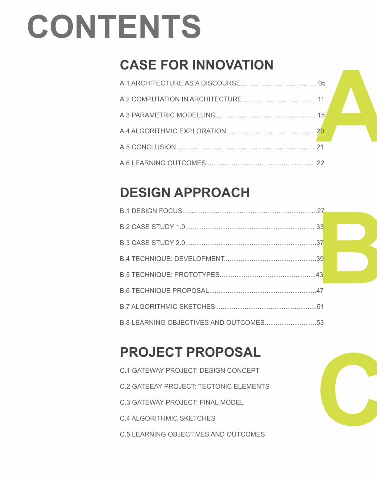
CONTENTS
AB
CASE FOR INNOVATION A.1 ARCHITECTURE AS A DISCOURSE......................................... 05
A.2 COMPUTATION IN ARCHITECTURE........................................ 11
A.3 PARAMETRIC MODELLING...................................................... 15
A.4 ALGORITHMIC EXPLORATION................................................ 20
A.5 CONCLUSION........................................................................... 21
A.6 LEARNING OUTCOMES........................................................... 22
DESIGN APPROACHB.1 DESIGN FOCUS.........................................................................27
B.2 CASE STUDY 1.0...................................................................... 33
B.3 CASE STUDY 2.0.......................................................................37
B.4 TECHNIQUE: DEVELOPMENT..................................................39
B.5 TECHNIQUE: PROTOTYPES....................................................43
B.6 TECHNIQUE PROPOSAL..........................................................47
B.7 ALGORITHMIC SKETCHES.......................................................51
B.8 LEARNING OBJECTIVES AND OUTCOMES............................53
PROJECT PROPOSALC.1 GATEWAY PROJECT: DESIGN CONCEPT
C.2 GATEEAY PROJECT: TECTONIC ELEMENTS
C.3 GATEWAY PROJECT: FINAL MODEL
C.4 ALGORITHMIC SKETCHES
C.5 LEARNING OBJECTIVES AND OUTCOMES
C

PART AEOI: CASE FOR INNOVATION

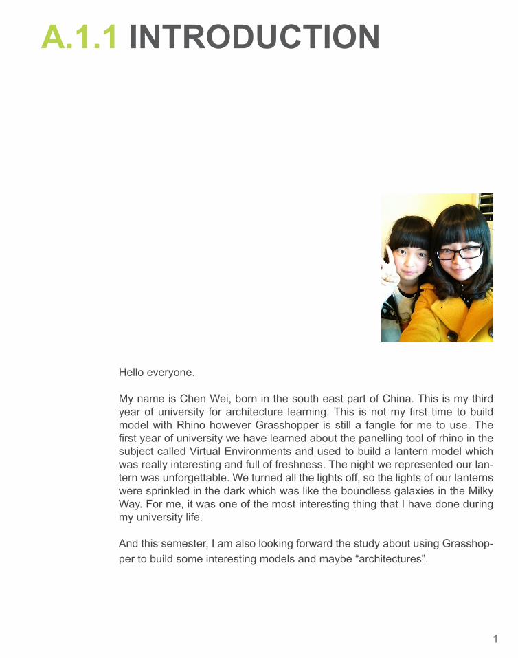
Hello everyone.
My name is Chen Wei, born in the south east part of China. This is my third year of university for architecture learning. This is not my first time to build model with Rhino however Grasshopper is still a fangle for me to use. The first year of university we have learned about the panelling tool of rhino in the subject called Virtual Environments and used to build a lantern model which was really interesting and full of freshness. The night we represented our lan-tern was unforgettable. We turned all the lights off, so the lights of our lanterns were sprinkled in the dark which was like the boundless galaxies in the Milky Way. For me, it was one of the most interesting thing that I have done during my university life.
And this semester, I am also looking forward the study about using Grasshop-per to build some interesting models and maybe “architectures”.
A.1.1 INTRODUCTION
1
My idea about architecture as a discourse starts from Franck Floyd Wright's organic architecture :
…architecture is life; or at least it is life itself taking form and therefore it is the truest record of life as it was live in the world yesterday, as it is lived today or ever will be lived.
- Franck Lloyd Wright (1970)
2
A.1.2 ARCHITECTURE AS A DISCOURSE
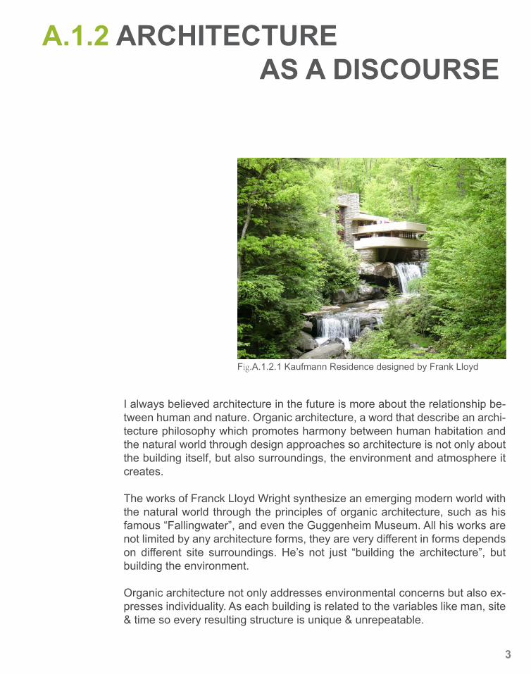
I always believed architecture in the future is more about the relationship be-tween human and nature. Organic architecture, a word that describe an archi-tecture philosophy which promotes harmony between human habitation and the natural world through design approaches so architecture is not only about the building itself, but also surroundings, the environment and atmosphere it creates.
The works of Franck Lloyd Wright synthesize an emerging modern world with the natural world through the principles of organic architecture, such as his famous “Fallingwater”, and even the Guggenheim Museum. All his works are not limited by any architecture forms, they are very different in forms depends on different site surroundings. He’s not just “building the architecture”, but building the environment.
Organic architecture not only addresses environmental concerns but also ex-presses individuality. As each building is related to the variables like man, site & time so every resulting structure is unique & unrepeatable.
Fig.A.1.2.1 Kaufmann Residence designed by Frank Lloyd
3
“Architecture is not about form.”
- Peter Zumthor
4
“Architecture is not about form, it is about many other things……The light and the use, and the structure, and the shadow, the smell and so on. I think form is the easiest to control, it can be done at the end.” - Peter Zumthor (Frearson, 2013)
Based on the idea of organic architecture from Franck Lloyd Wright and also opinions from Peter Zumthor, to my way of thinking, architecture is not just a piece of artwork, it is not an independent existing thing but a comprehensive existence. It is important to see architectures that suit to the particular site that it stands as no one site is ever the same, so each piece of architecture would be unique and unrepeatable.
Architecture is not only about build the building, the material structure, but also build the environment, the atmosphere and a kind of experience that people can go through.
In my opinion, architecture should not be a single. It relates to time, place and people. A building relates to time so that the building will belong to the era when it was created. It can reflect the life-styles, social patterns and condi-tions at a particular time from the materials it used and technological methods that involved. A building related to place means it creates a harmony between itself and the natural environment surrounded. And particular proportions, ma-terials, design and technology will be used in order to suit to its site. (Bruce Brooks Pfeiffer. 2009) And the reflection of humanity and different cultures is also important to a building.
A.1.2 ARCHITECTURE AS A DISCOURSE
5
A.1.3 SYDNEY OPERA HOUSE
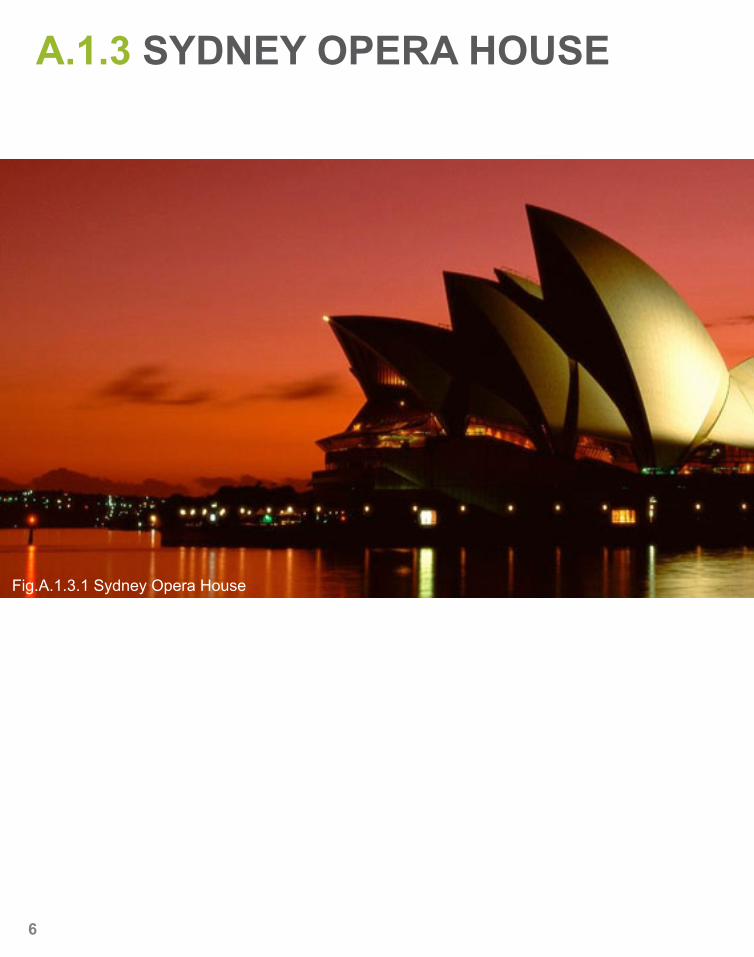
Fig.A.1.3.1 Sydney Opera House
6
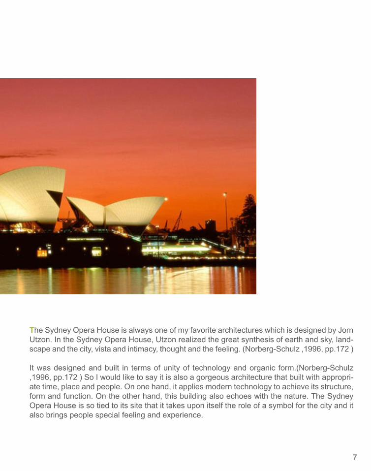
The Sydney Opera House is always one of my favorite architectures which is designed by Jorn Utzon. In the Sydney Opera House, Utzon realized the great synthesis of earth and sky, land-scape and the city, vista and intimacy, thought and the feeling. (Norberg-Schulz ,1996, pp.172 )
It was designed and built in terms of unity of technology and organic form.(Norberg-Schulz ,1996, pp.172 ) So I would like to say it is also a gorgeous architecture that built with appropri-ate time, place and people. On one hand, it applies modern technology to achieve its structure, form and function. On the other hand, this building also echoes with the nature. The Sydney Opera House is so tied to its site that it takes upon itself the role of a symbol for the city and it also brings people special feeling and experience.
7
A.1.3 THE BLUE PLANET
8
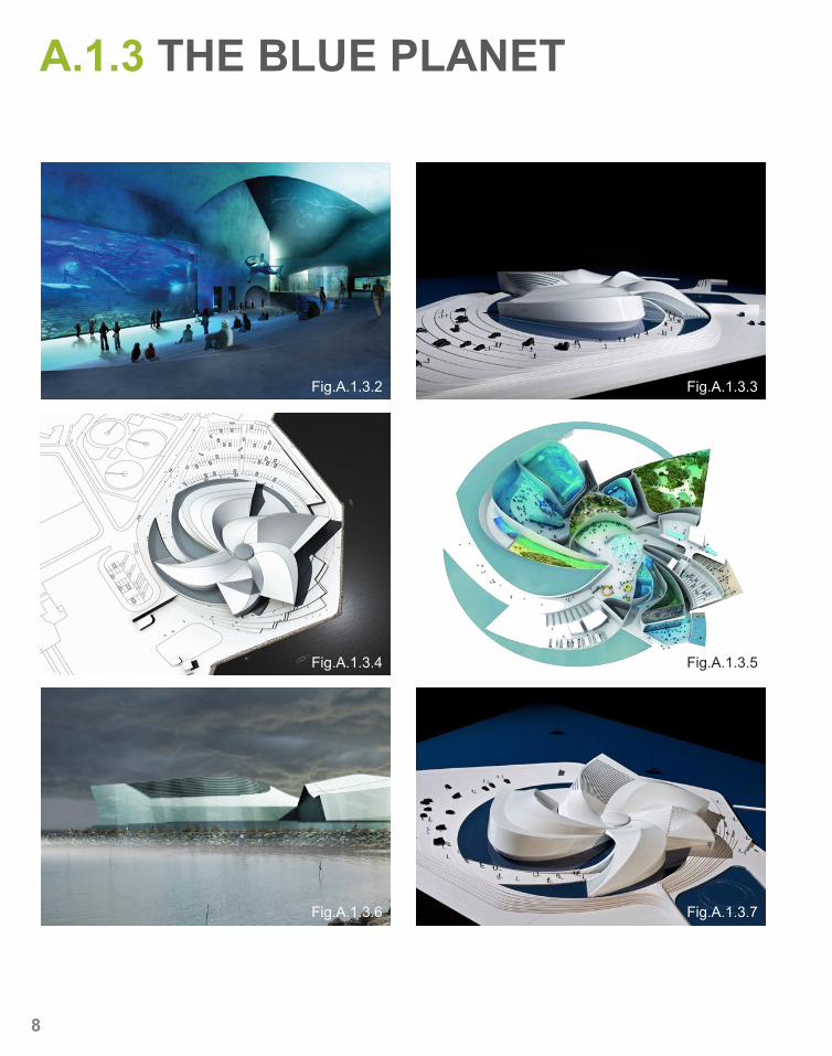
Fig.A.1.3.2 Fig.A.1.3.3
Fig.A.1.3.4
Fig.A.1.3.6 Fig.A.1.3.7
Fig.A.1.3.5
The Blue Planet – Denmark’s new aquarium is one of my favorite architecture designs recently. It is designed by the architects of 3XN and it is located at Kastrup Yacht Harbour, Copenhagen. This new aquarium is still under con-struction and it is planned to complete in 2013.
The most anticipated part for me is that the new aquarium is surrounded by water on all sides as the architects want to give visitors an experience of em-barking on an underwater journey and this is also the reason that they use the shape of a giant swirl as an inspiration for this building. This design gives a feeling that it will suck visitors into it depths. It shows a strong connection with the water, the sea.
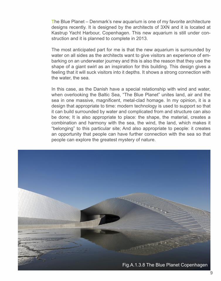
In this case, as the Danish have a special relationship with wind and water, when overlooking the Baltic Sea, “The Blue Planet” unites land, air and the sea in one massive, magnificent, metal-clad homage. In my opinion, it is a design that appropriate to time: modern technology is used to support so that it can build surrounded by water and complicated from and structure can also be done; It is also appropriate to place: the shape, the material, creates a combination and harmony with the sea, the wind, the land, which makes it “belonging” to this particular site; And also appropriate to people: it creates an opportunity that people can have further connection with the sea so that people can explore the greatest mystery of nature.
Fig.A.1.3.8 The Blue Planet Copenhagen
9

10
A.2.1 COMPUTATIONAL ARCHITECTURE
Digital technologies are changing architectural practices in ways that few were able to anticipate just a decade ago. In the conceptual realm, computational, digital architectures of topological, non-Euclidean geometric space, kinetic and dynamic systems, and genetic algorithms, are supplanting technological architectures.(Branko Kolarevic, 2003, pp.117)
For the past 10 years, computational tools and techniques are having a strong impact on architecture design however since the technology changed so fast, computational tools are not only treated as a tool or helper for designers, but also become a method for design process which can explore new possibili-ties and challenges occurring. They can be used to explore spatial, structural and geometrical conditions, leading to the emergence of abstract prototypes. Then such abstract prototypes can be further developed, which can be used to generate architectural solutions. Based on that, structural systems, typol-ogy, form, organization of program or detail solutions can be figured out as well. And Branko Kolarevic also mentioned in his paper that the use of digital modeling (three-dimensional) and animation (four-dimensional) software has opened new territories of formal exploration in architecture.
Technology is a symbol of the times and it helps us to achieve generate com-plex forms in design and solve some intractable design problems. Many of architecture designs nowadays are beneficial from the technology develop-ment. “…the processes of describing and constructing a design can be ex-tracted, exchanged, and utilized with far greater facility and speed.” (Branko Kolarevic, 2003, pp.10) As digital data can be passed directly from designers to the implementer such as engineers, the design and construction process-es become more efficient. And in Branko Kolarevic’s paper, he used Gehry’s office as an example to show the “paperless” process of digital production.(Branko Kolarevic, 2003, pp.60)
And nowadays, digital programs are widely used in architecture design. Ben-efits of using digital technology in design area are easily to find such as gene-tating complex forms and solving intractable design problems as mentioned above however issues are also coexistent when such technologies are in-volved. Two precedents I chose are both regarded as computational architec-tures and further discussion will be made.
11
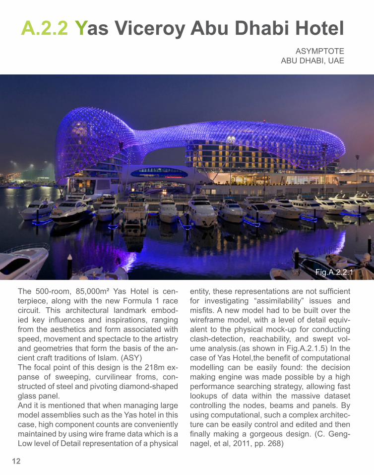
A.2.2 Yas Viceroy Abu Dhabi HotelASYMPTOTE
ABU DHABI, UAE
The 500-room, 85,000m² Yas Hotel is cen-terpiece, along with the new Formula 1 race circuit. This architectural landmark embod-ied key influences and inspirations, ranging from the aesthetics and form associated with speed, movement and spectacle to the artistry and geometries that form the basis of the an-cient craft traditions of Islam. (ASY)The focal point of this design is the 218m ex-panse of sweeping, curvilinear froms, con-structed of steel and pivoting diamond-shaped glass panel. And it is mentioned that when managing large model assemblies such as the Yas hotel in this case, high component counts are conveniently maintained by using wire frame data which is a Low level of Detail representation of a physical
entity, these representations are not sufficient for investigating “assimilability” issues and misfits. A new model had to be built over the wireframe model, with a level of detail equiv-alent to the physical mock-up for conducting clash-detection, reachability, and swept vol-ume analysis.(as shown in Fig.A.2.1.5) In the case of Yas Hotel,the benefit of computational modelling can be easily found: the decision making engine was made possible by a high performance searching strategy, allowing fast lookups of data within the massive dataset controlling the nodes, beams and panels. By using computational, such a complex architec-ture can be easily control and edited and then finally making a gorgeous design. (C. Geng-nagel, et al, 2011, pp. 268)
Fig.A.2.2.1
12
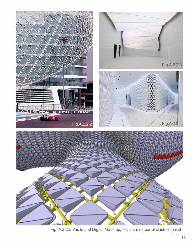
Fig. A.2.2.5 Yas Island Digital Mock-up, Highlighting panel clashes in red
Fig.A.2.2.2
Fig.A.2.2.3
Fig.A.2.2.4
13

14
A.3.1 PARAMETRIC MODELLING
Parametric modeling represents change. It is an old idea, indeed one of the very first ideas in computer-aided design. (Woodbury, R., 2010, pp.7) Un-like most project management tools which focus on automating features or workflow, parametric, predictive modeling tools help organizations model and optimize project feasibility and ensure that projects meet established deliv-ery guidelines. Parametric models are built from a set of mathematical equa-tions. Designers are used to working in this mode; add marks and take them away, with conventions for relating marks together. Parametric modeling (also known as constraint modeling) introduces a fundamental change: “marks” , that is, parts of a design, relate and change together in a coordinated way. Parametric modeling (also known as constraint modeling) introduces a funda-mental change: “marks” , that is, parts o f a design, relate and change together in a coordinated way. No longer must designers simply add and erase. They now add, erase, relate and repair. The act of relating requires explicit think-ing about the kind of relation: is this point on the line, or near to it? Repairing occurs after an erasure, when the parts that depend on an erased part are related again to the parts that remain. Relating and repairing impose funda-mental changes on systems and the work that is done with them.
Of all types of parametric modeling, propagation has the relative advantages of reliability, speed and clarity. It is used in spreadsheets, dataflow program-ming and computer-aided design due to the efficiency of its algorithms and simplicity of the decision-making required of the user. We can realize our pur-pose to control, draw or build some particular structures. It is an efficient way which is more easy to control. However, the disadvantage is that designers should learn about the program themselves and use special word to control their design. They need to be able to programmed the system as they like,not be programmed by the system. Unfortunately some of the system are hard and complex to learn so that it will take much time.
At present, parametric modeling is more and more popular in the world and more fantastic functions and approaches are added into. It is efficient and controllable although some hard skills are required. Almost all the modern architectures are based on this system. In terms of gateway project, the Brit-ish Museum Great Court and the the Louvre Abu Dhabi are two examples to show projects can be done easier and more efficiency by using parametric modelling.
15
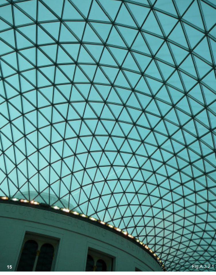
Fig.A.3.2.115
A.3.2 British Museum Great CourtFoster + PartnersLondon, UK
The British Museum is located in London and the design for the glazed roof and circular Reading Room has proved to be highly influential.
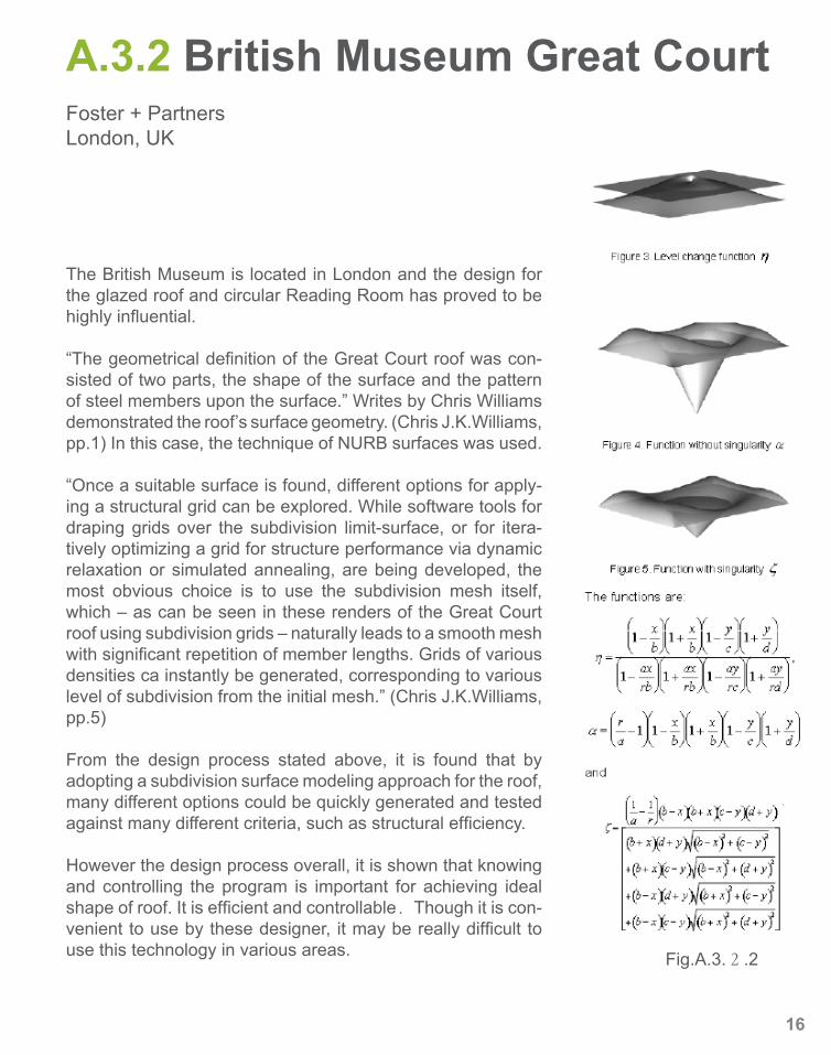
“The geometrical definition of the Great Court roof was con-sisted of two parts, the shape of the surface and the pattern of steel members upon the surface.” Writes by Chris Williams demonstrated the roof’s surface geometry. (Chris J.K.Williams, pp.1) In this case, the technique of NURB surfaces was used.
“Once a suitable surface is found, different options for apply-ing a structural grid can be explored. While software tools for draping grids over the subdivision limit-surface, or for itera-tively optimizing a grid for structure performance via dynamic relaxation or simulated annealing, are being developed, the most obvious choice is to use the subdivision mesh itself, which – as can be seen in these renders of the Great Court roof using subdivision grids – naturally leads to a smooth mesh with significant repetition of member lengths. Grids of various densities ca instantly be generated, corresponding to various level of subdivision from the initial mesh.” (Chris J.K.Williams, pp.5)
From the design process stated above, it is found that by adopting a subdivision surface modeling approach for the roof, many different options could be quickly generated and tested against many different criteria, such as structural efficiency.
However the design process overall, it is shown that knowing and controlling the program is important for achieving ideal shape of roof. It is efficient and controllable.Though it is con-venient to use by these designer, it may be really difficult to use this technology in various areas. Fig.A.3.2.2
16
A.3.3 LOUVRE ABU DHABIAteliers Jean Nouvel
Abu Dhabi, UAE
17
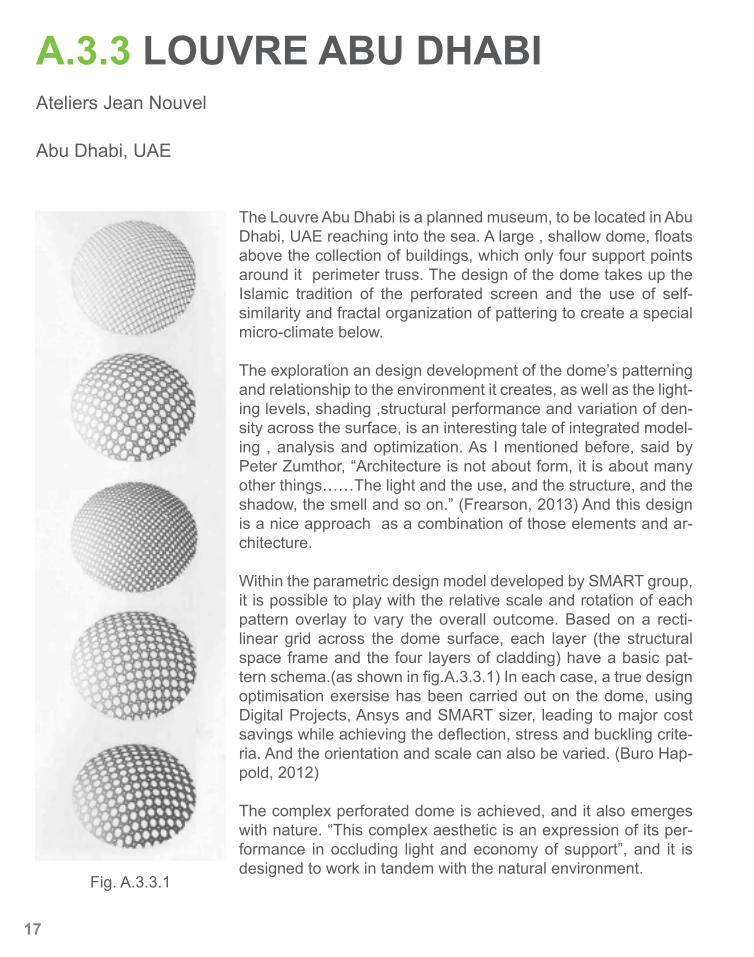
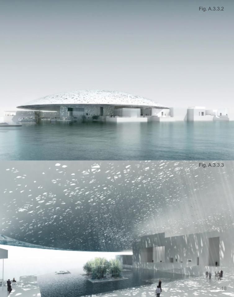
The Louvre Abu Dhabi is a planned museum, to be located in Abu Dhabi, UAE reaching into the sea. A large , shallow dome, floats above the collection of buildings, which only four support points around it perimeter truss. The design of the dome takes up the Islamic tradition of the perforated screen and the use of self-similarity and fractal organization of pattering to create a special micro-climate below.
The exploration an design development of the dome’s patterning and relationship to the environment it creates, as well as the light-ing levels, shading ,structural performance and variation of den-sity across the surface, is an interesting tale of integrated model-ing , analysis and optimization. As I mentioned before, said by Peter Zumthor, “Architecture is not about form, it is about many other things……The light and the use, and the structure, and the shadow, the smell and so on.” (Frearson, 2013) And this design is a nice approach as a combination of those elements and ar-chitecture.
Within the parametric design model developed by SMART group, it is possible to play with the relative scale and rotation of each pattern overlay to vary the overall outcome. Based on a recti-linear grid across the dome surface, each layer (the structural space frame and the four layers of cladding) have a basic pat-tern schema.(as shown in fig.A.3.3.1) In each case, a true design optimisation exersise has been carried out on the dome, using Digital Projects, Ansys and SMART sizer, leading to major cost savings while achieving the deflection, stress and buckling crite-ria. And the orientation and scale can also be varied. (Buro Hap-pold, 2012)
The complex perforated dome is achieved, and it also emerges with nature. “This complex aesthetic is an expression of its per-formance in occluding light and economy of support”, and it is designed to work in tandem with the natural environment.
Fig. A.3.3.1
18
Fig. A.3.3.2
Fig. A.3.3.3
19
Fig.A.4.1.1
Fig.A.4.1.2
A.4 ALGORITHMIC EXPLORATION
20
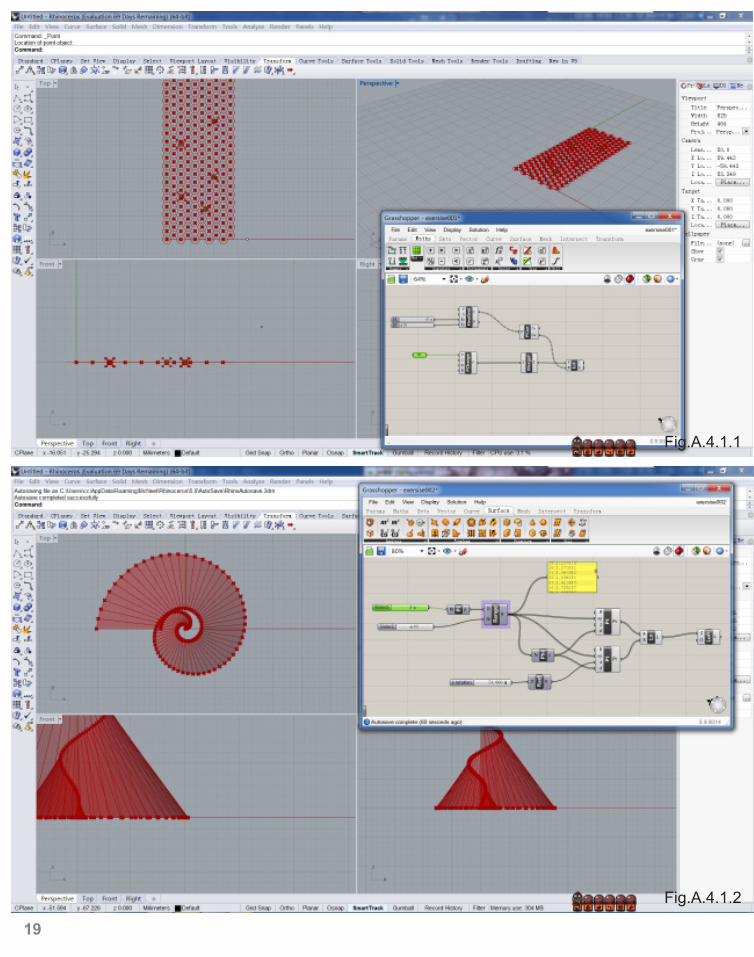
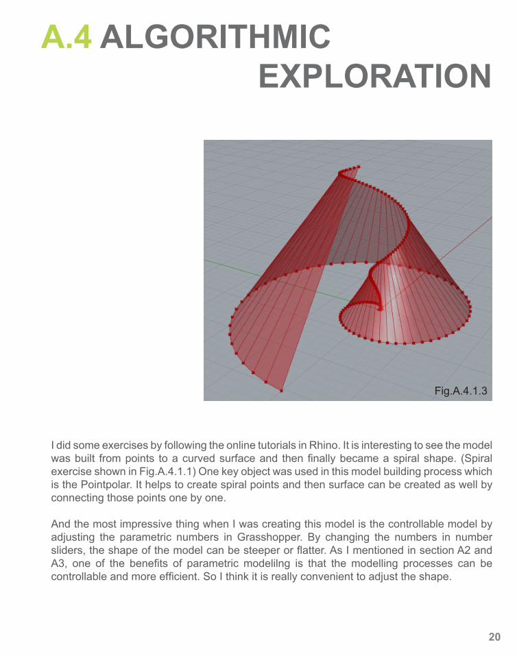
I did some exercises by following the online tutorials in Rhino. It is interesting to see the model was built from points to a curved surface and then finally became a spiral shape. (Spiral exercise shown in Fig.A.4.1.1) One key object was used in this model building process which is the Pointpolar. It helps to create spiral points and then surface can be created as well by connecting those points one by one.
And the most impressive thing when I was creating this model is the controllable model by adjusting the parametric numbers in Grasshopper. By changing the numbers in number sliders, the shape of the model can be steeper or flatter. As I mentioned in section A2 and A3, one of the benefits of parametric modelilng is that the modelling processes can be controllable and more efficient. So I think it is really convenient to adjust the shape.
Fig.A.4.1.3
A.5 CONCLUSION
21
“Architecture is recasting itself, becoming in part an experimental investigation of topological geometries, partly a computational orchestration of robotic material production and partly a generative, kinematic sculpting of space.” (Peter Zellner, 1999)
It is believed that architecture is not only about the form, but also the environments it creates and the experience that people can go through. In order to adapting to a particular site, somehow digital technologies such as parametric modelling help designers to achieve particular goals.
In recent years, parametric architecture has, as digital possibilities are explosively increasing, made up ground in the design industry, replacing the traditional archi-tecture which cherishes the purpose of traditional shapes of buildings. Therefore, the process can easily result in a number of different spatial solutions by replacing parameters.
During the computational architecture and parametric modeling sections, several precedents was represented to show these technology are becoming useful and helpful in architecture design. They are not only tools to help architects to achieve some designing solutions; more importantly, the process of using these methods for designing creates more possibilities. Digital technology in design area such as parametric modeling can be used for generating complex forms and solving intrac-table design problems however hard skills are also necessarily required.
All of the precedents I used before achieved some complex forms and structures by using digital technologies. Both the British Museum Great Court and the Louvre Abu Dhabi used parametric modelling to generate their surfaces and structures. Benefits of these two projects by using parametric modelling can be found easily such as different options can be quickly generated and tested against many differ-ent criteria including structural efficiency. By using parametric modeling method, design process becomes more efficient and controllable. It is also beneficial for designers to test and generate how architectures can emerge with nature and sur-rounding environments better.
A.6 LEARNING OUTCOMES
22
Fig.A.6.1.1
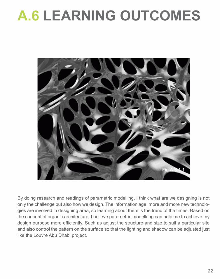
By doing research and readings of parametric modelling, I think what are we designing is not only the challenge but also how we design. The information age, more and more new technolo-gies are involved in designing area, so learning about them is the trend of the times. Based on the concept of organic architecture, I believe parametric modelking can help me to achieve my design purpose more efficiently. Such as adjust the structure and size to suit a particular site and also control the pattern on the surface so that the lighting and shadow can be adjusted just like the Louvre Abu Dhabi project.

23
REFERENCE- Franck Lloyd Wright, An Organic Architecture: the architecture of democracy, The MIT Press, 1970- Fig.A.1.2.1, http://usahomeandgarden.com/architecture/fallingwater/fallingwater.html- Frearson, A. “Architecture is not about form“ - Peter Zumthor, De zeen Magazine, viewed 21 March 2013, <http://www.dezeen.com/2013/02/06/peter-zumthor-at-the-royal-gold-medal-lecture-2013/>- Bruce Brooks Pfeiffer, “A Living Architecture”, Frank Lloyd Wright, 1943-1959: The Complete Works, Taschen, 2009- Fig.A.1.3.1 http://www.rydges.com/accommodation/sydney-nsw/world-square-sydney-cbd/local-area/in-the- area/sydney-opera-house/- Norberg-Schulz, C 1996, ‘The Sydney Opera House: international comparison, an evaluation of its position in the history of modern architecture’, Department of the Environment, Sports and Territories and New South Wales Department of Urban Affairs and Planning Sydney Opera House in its harbour setting, unpub lished World Heritage nomination by the Government of Australia, DEST & DUAP, Sydney, pp,172- Fig.A.1.3.2 - 7 http://www.tuvie.com/the-blue-planet-conpenhagen-aquarium-in-2013-by-3xn/- Fig.A.1.3.8 http://www.e-architect.co.uk/architecture_news.htm- Background information, <http://www.advancedaquarist.com/blog/the-blue-planet-aquarium-denmark>, viewed 25 March, 2013- Kolarevic, Branko, Architecture in the Digital Age: Design and Manufacturing (New York; Lon- don: Spon Press, 2003), pp. 3 - 28.(pdf ) COMMENTED.- KOLAREVIC, Branko, Designing and Manufacturing Architecture in the Digital Age, University of Pennsylvania, USA, 2003, pp.117, viewed 29 March 2013, <http://www.design.upenn.edu/>- ASY, The Yas Hotel, ASYMPTOTE ARCHITECTURE, viewed 29 March 2013, < http://www.asymptote.net/build ings/yas-hotel/#>- Fig.A.2.2.1, http://www.yasisland.ae/en/visiting/discover-yas-island/attractions/yas-viceroy-abu-dhabi/- Fig.A.2.2.2 - 4, http://www.asymptote.net/buildings/yas-hotel/- Fig.A.2.2.5, C. Gengnagel, University of the Arts, Berlin A. Kilian PhD, Princetion University, Priceton N. Palz, University of the Arts, Berlin F. Scheurer, Architectural Association, Zurich Editors, Computaitonal Design Model ing: Proceedings of the Design Modeling Symposium. Berlin 2011, pp.268, viewed 29 March 2013- Chris J. K. Williams, Definition of the geometry of the British Museum Great Court roof, Department of Architecture and Civil Engineering, University of Bath, UK, viewed 31 March 2013, <http://people.bath.ac.uk/ps281/research/ publications/burry_preprint.pdf>- Woodbury, Robert (2010). Elements of Parametric Design (London: Routledge) pp. 7-48- Buro Happold,SMART Structural Solutions: Capability Statement 2012, 2012, viewed 31 March 2013, <smart. burohappold.com> - Fig.A.3.2.1 http://randomwire.com/london-report- Fig.A.3.2.2 http://people.bath.ac.uk/ps281/research/publications/burry_preprint.pdf- Fig.A.3.3.1 http://digiitalarchfab.com/portal/resources/parametric-project-precedents/- Fig.A.3.3.2-3 http://www.archdaily.com/298058/the-louvre-abu-dhabi-museum-ateliers-jean-nouvel/ajn_abu_ dhabi_louvre_view3/ - Fig.A.5.1.1 http://www.luxuo.com/art/louvre-abu-dhabi-museum.html- Fig.A.6.1.1 http://mikkokanninen.com/new/en/parametric.html- Zellner, Peter, Hybrid Space: New Forms in Digital Architecture. New York: Rizzoli Interna tional Publications, 1999
24

PART BEOI II: DESIGN APPROACH
B.1 DESIGN FOCUS
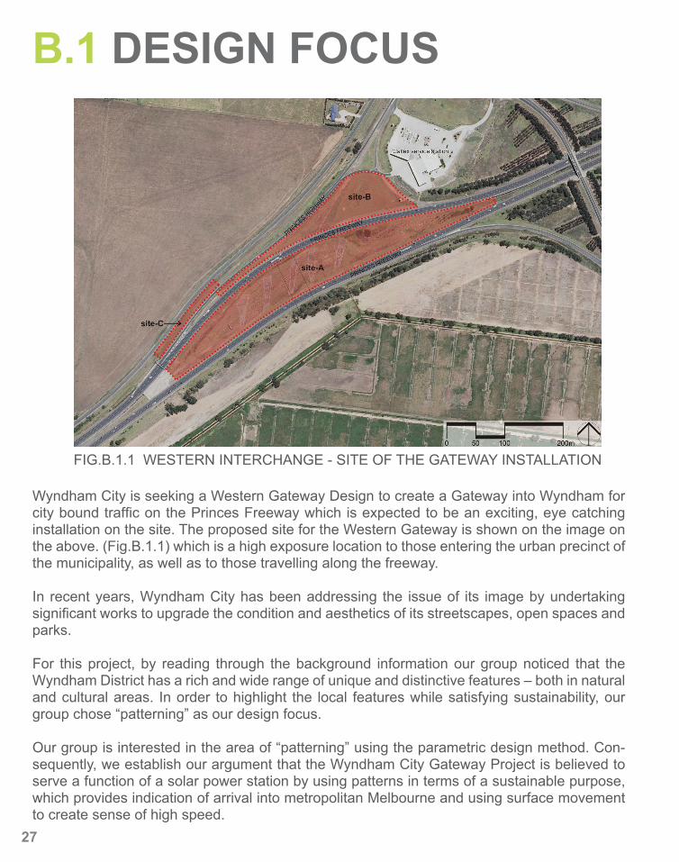
FIG.B.1.1 WESTERN INTERCHANGE - SITE OF THE GATEWAY INSTALLATION
Wyndham City is seeking a Western Gateway Design to create a Gateway into Wyndham for city bound traffic on the Princes Freeway which is expected to be an exciting, eye catching installation on the site. The proposed site for the Western Gateway is shown on the image on the above. (Fig.B.1.1) which is a high exposure location to those entering the urban precinct of the municipality, as well as to those travelling along the freeway.
In recent years, Wyndham City has been addressing the issue of its image by undertaking significant works to upgrade the condition and aesthetics of its streetscapes, open spaces and parks.
For this project, by reading through the background information our group noticed that the Wyndham District has a rich and wide range of unique and distinctive features – both in natural and cultural areas. In order to highlight the local features while satisfying sustainability, our group chose “patterning” as our design focus.
Our group is interested in the area of “patterning” using the parametric design method. Con-sequently, we establish our argument that the Wyndham City Gateway Project is believed to serve a function of a solar power station by using patterns in terms of a sustainable purpose, which provides indication of arrival into metropolitan Melbourne and using surface movement to create sense of high speed.
27
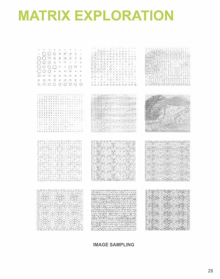
MATRIX EXPLORATION
IMAGE SAMPLING
28
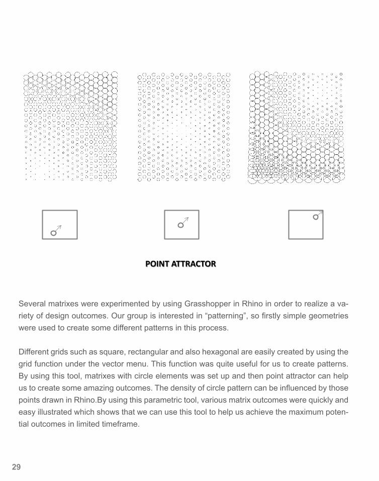
POINT ATTRACTOR
Several matrixes were experimented by using Grasshopper in Rhino in order to realize a va-riety of design outcomes. Our group is interested in “patterning”, so firstly simple geometries were used to create some different patterns in this process.
Different grids such as square, rectangular and also hexagonal are easily created by using the grid function under the vector menu. This function was quite useful for us to create patterns. By using this tool, matrixes with circle elements was set up and then point attractor can help us to create some amazing outcomes. The density of circle pattern can be influenced by those points drawn in Rhino.By using this parametric tool, various matrix outcomes were quickly and easy illustrated which shows that we can use this tool to help us achieve the maximum poten-tial outcomes in limited timeframe.
29
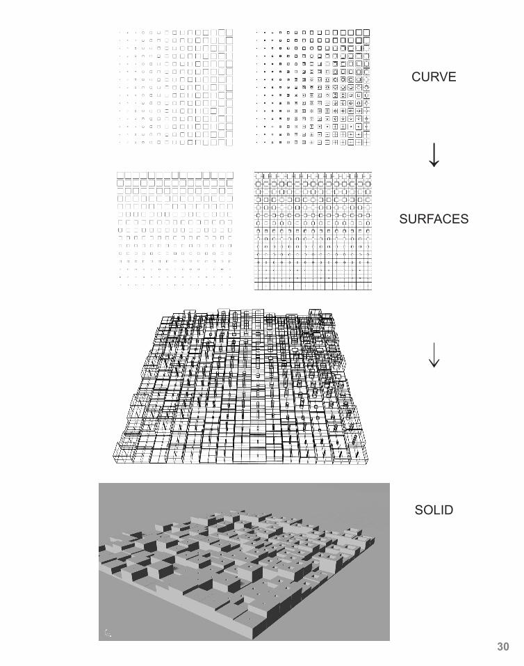
CURVE
↓
SURFACES
↓
SOLID
30
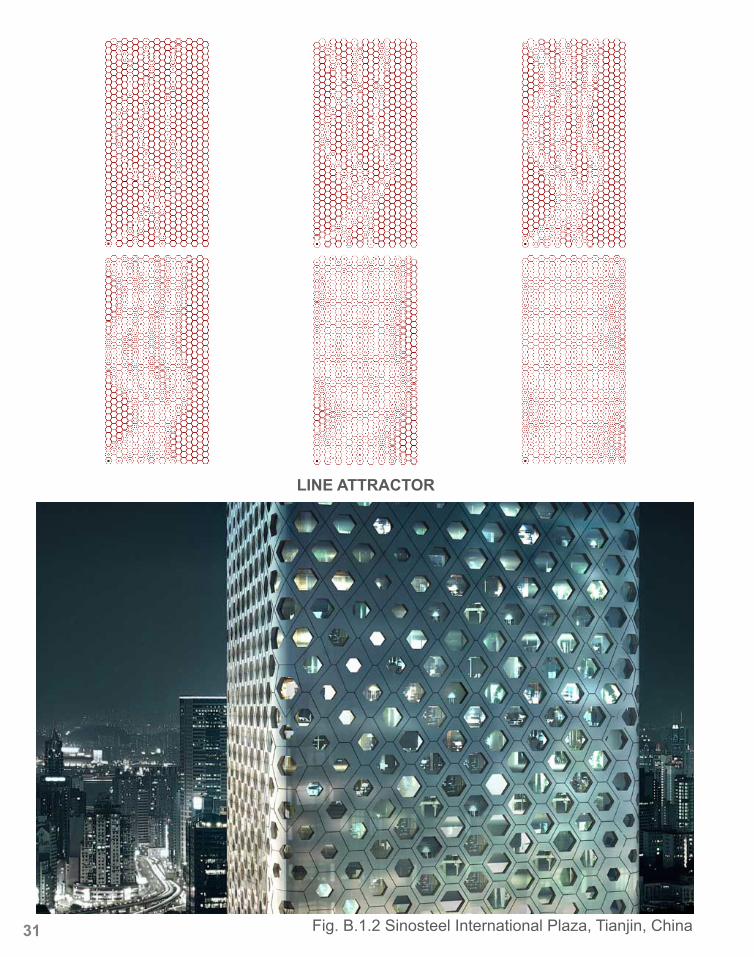
LINE ATTRACTOR
Fig. B.1.2 Sinosteel International Plaza, Tianjin, China31
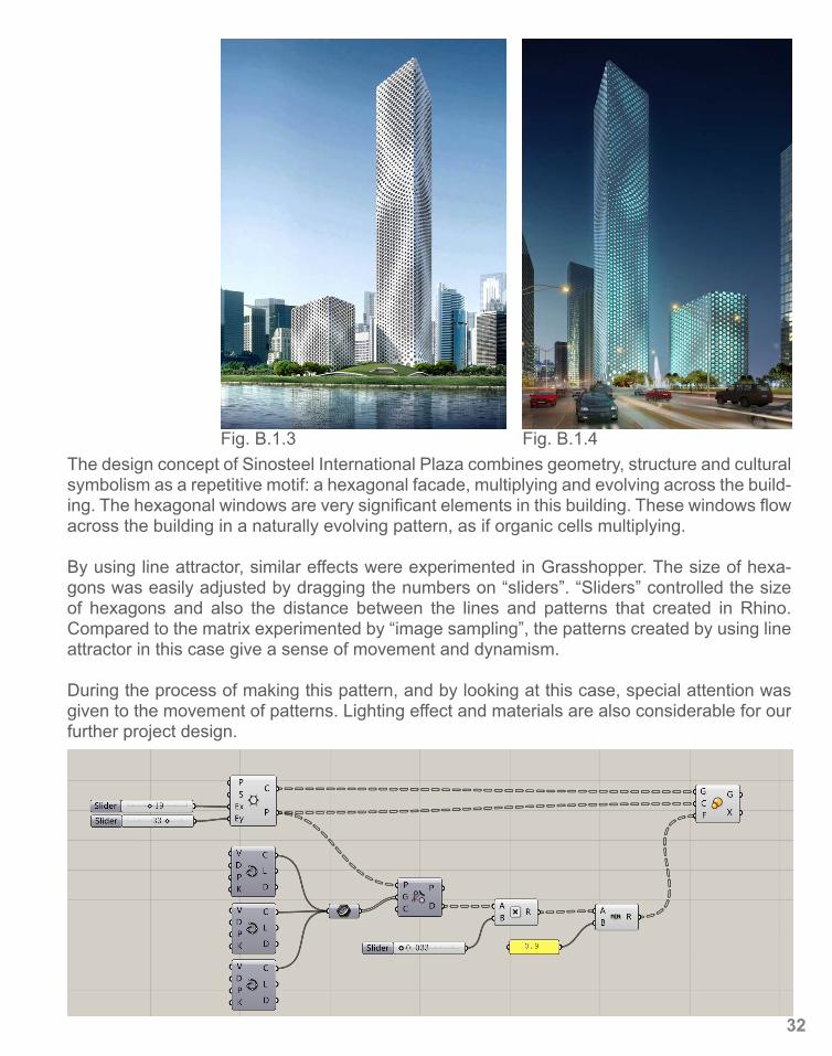
Fig. B.1.3 Fig. B.1.4The design concept of Sinosteel International Plaza combines geometry, structure and cultural symbolism as a repetitive motif: a hexagonal facade, multiplying and evolving across the build-ing. The hexagonal windows are very significant elements in this building. These windows flow across the building in a naturally evolving pattern, as if organic cells multiplying.
By using line attractor, similar effects were experimented in Grasshopper. The size of hexa-gons was easily adjusted by dragging the numbers on “sliders”. “Sliders” controlled the size of hexagons and also the distance between the lines and patterns that created in Rhino. Compared to the matrix experimented by “image sampling”, the patterns created by using line attractor in this case give a sense of movement and dynamism.
During the process of making this pattern, and by looking at this case, special attention was given to the movement of patterns. Lighting effect and materials are also considerable for our further project design.
32
B.2 CASE STUDY 1.0
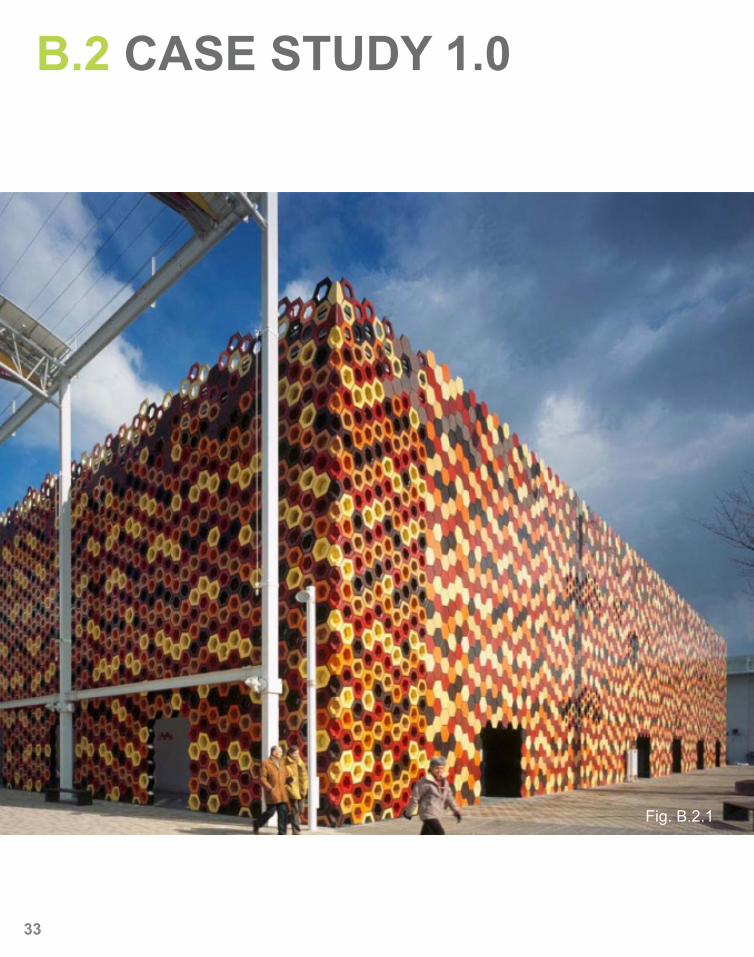
Fig. B.2.1
33
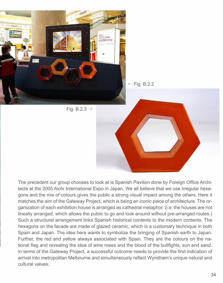
← Fig. B.2.2
Fig. B.2.3 →
The precedent our group chooses to look at is Spanish Pavilion done by Foreign Office Archi-tects at the 2005 Aichi International Expo in Japan. We all believe that we use irregular hexa-gons and the mix of colours gives the public a strong visual impact among the others. Here it matches the aim of the Gateway Project, which is being an iconic piece of architecture. The or-ganization of each exhibition house is arranged as cathedral metaphor. (i.e. the houses are not lineally arranged, which allows the public to go and look around without pre-arranged routes.) Such a structural arrangement links Spanish historical contents to the modern contents. The hexagons on the facade are made of glazed ceramic, which is a customary technique in both Spain and Japan. The idea here wants to symbolize the bringing of Spanish earth to Japan. Further, the red and yellow always associated with Spain. They are the colours on the na-tional flag and revealing the idea of wine roses and the blood of the bullfights, sun and sand. In terms of the Gateway Project, a successful outcome needs to provide the first indication of arrival into metropolitan Melbourne and simultaneously reflect Wyndham’s unique natural and cultural values.
34
35
36
B.3 CASE STUDY 2.0
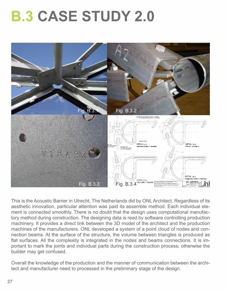
This is the Acoustic Barrier in Utrecht, The Netherlands did by ONL Architect. Regardless of its aesthetic innovation, particular attention was paid its assemble method. Each individual ele-ment is connected smoothly. There is no doubt that the design uses computational manufac-tory method during construction. The designing data is read by software controlling production machinery. It provides a direct link between the 3D model of the architect and the production machines of the manufacturers. ONL developed a system of a point cloud of nodes and con-nection beams. At the surface of the structure, the volume between triangles is produced as flat surfaces. All the complexity is integrated in the nodes and beams connections. It is im-portant to mark the joints and individual parts during the construction process; otherwise the builder may get confused.
Overall the knowledge of the production and the manner of communication between the archi-tect and manufacturer need to processed in the preliminary stage of the design.
Fig. B.3.1 Fig. B.3.2
Fig. B.3.3 Fig. B.3.4
37
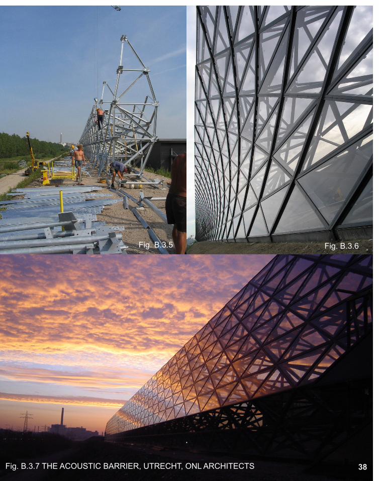
Fig. B.3.5 Fig. B.3.6
Fig. B.3.7 THE ACOUSTIC BARRIER, UTRECHT, ONL ARCHITECTS 38
B.4 TECHNIQUE: DEVELOPMENT
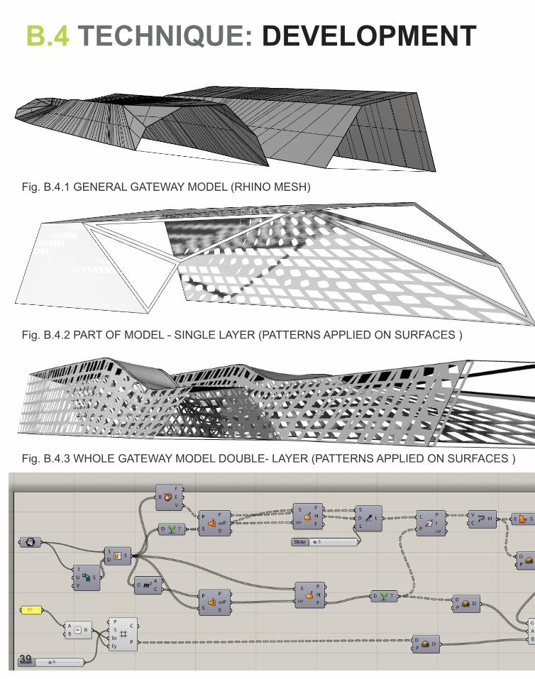
Fig. B.4.1 GENERAL GATEWAY MODEL (RHINO MESH)
Fig. B.4.2 PART OF MODEL - SINGLE LAYER (PATTERNS APPLIED ON SURFACES )
Fig. B.4.3 WHOLE GATEWAY MODEL DOUBLE- LAYER (PATTERNS APPLIED ON SURFACES )
39
40
In order to achieve our design concept of “sense of speed”, the idea of “optical fiber” was used for inspiration of our digital model at the very beginning. Two long tunnels were created in Rhino which was an anal-ogy of the optical fiber pipelines. This idea was also refer to the concept that the Gateway should be an indication of arrival into metropolitan.
Curved “lines” was drawn along the highway by a 1:100 scale in Rhino. By adjusting the position of each lines in Rhino and then using the tool ”loft”, the basic digital model was created. (As shown in Fig.B.4.1)
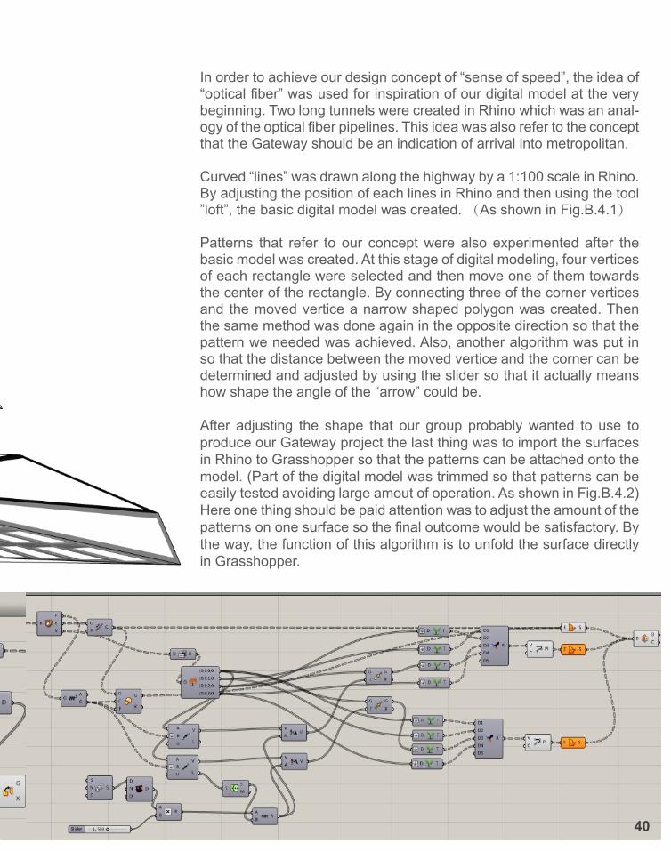
Patterns that refer to our concept were also experimented after the basic model was created. At this stage of digital modeling, four vertices of each rectangle were selected and then move one of them towards the center of the rectangle. By connecting three of the corner vertices and the moved vertice a narrow shaped polygon was created. Then the same method was done again in the opposite direction so that the pattern we needed was achieved. Also, another algorithm was put in so that the distance between the moved vertice and the corner can be determined and adjusted by using the slider so that it actually means how shape the angle of the “arrow” could be.
After adjusting the shape that our group probably wanted to use to produce our Gateway project the last thing was to import the surfaces in Rhino to Grasshopper so that the patterns can be attached onto the model. (Part of the digital model was trimmed so that patterns can be easily tested avoiding large amout of operation. As shown in Fig.B.4.2)Here one thing should be paid attention was to adjust the amount of the patterns on one surface so the final outcome would be satisfactory. By the way, the function of this algorithm is to unfold the surface directly in Grasshopper.
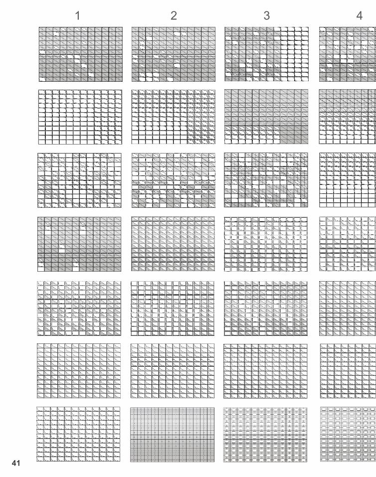
1 2 3 4 5 6 7
41
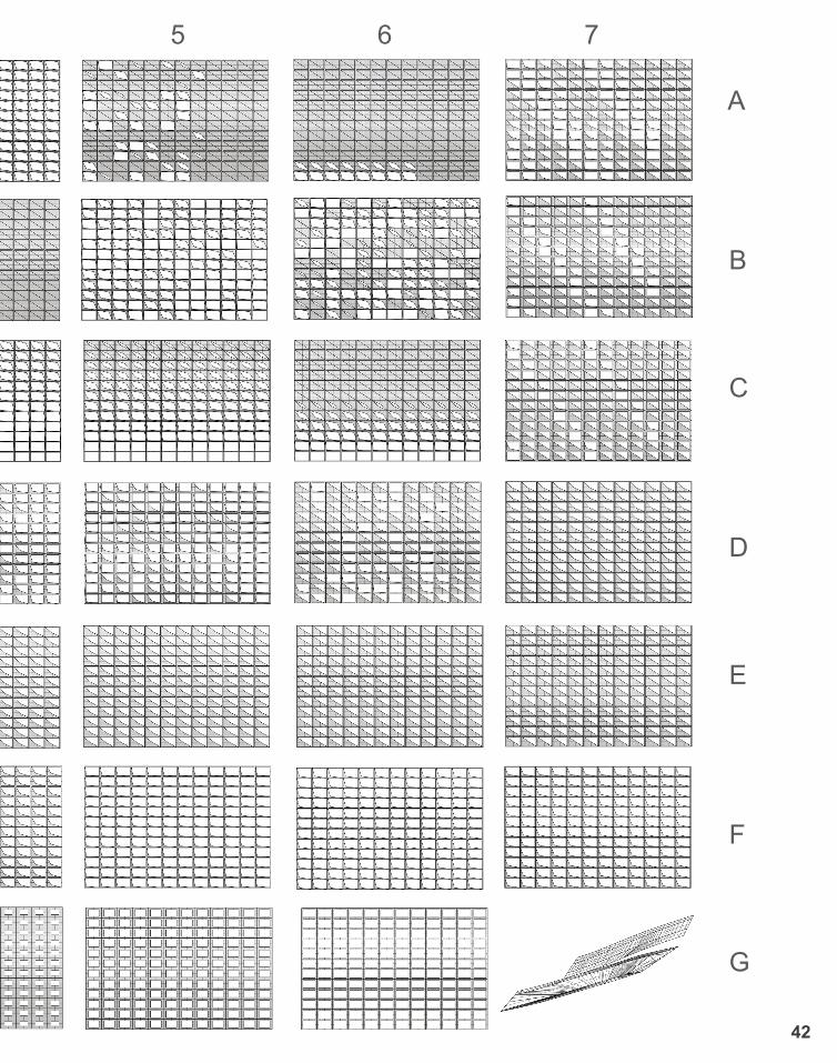
1 2 3 4 5 6 7 A
B
C
D
E
F
G
42
B.5 TECHNIQUE: PROTOTYPES TESTING THE PRELIMINARY DESIGN
43
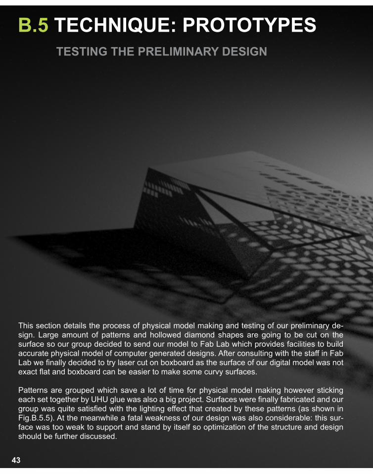
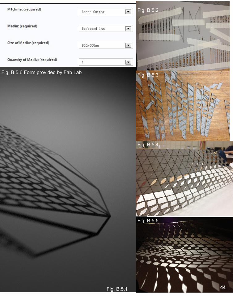
This section details the process of physical model making and testing of our preliminary de-sign. Large amount of patterns and hollowed diamond shapes are going to be cut on the surface so our group decided to send our model to Fab Lab which provides facilities to build accurate physical model of computer generated designs. After consulting with the staff in Fab Lab we finally decided to try laser cut on boxboard as the surface of our digital model was not exact flat and boxboard can be easier to make some curvy surfaces.
Patterns are grouped which save a lot of time for physical model making however sticking each set together by UHU glue was also a big project. Surfaces were finally fabricated and our group was quite satisfied with the lighting effect that created by these patterns (as shown in Fig.B.5.5). At the meanwhile a fatal weakness of our design was also considerable: this sur-face was too weak to support and stand by itself so optimization of the structure and design should be further discussed.
44Fig. B.5.1
Fig. B.5.5
Fig. B.5.4
Fig. B.5.3
Fig. B.5.2
Fig. B.5.6 Form provided by Fab Lab
45
Fig. B.5.6
Fig. B.5.7
Fig. B.5.8
Fig. B.5.9
Fig. B.5.10
Fig. B.5.11
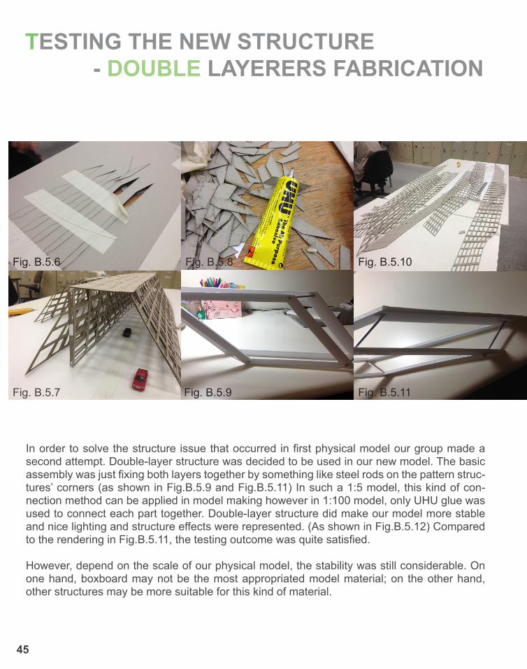
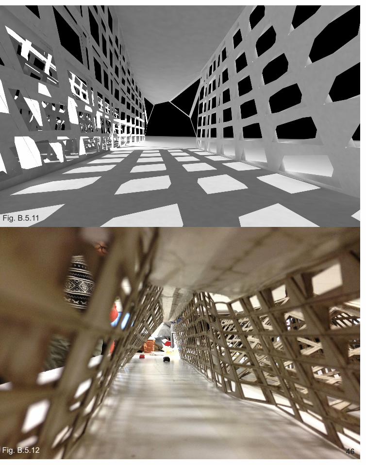
In order to solve the structure issue that occurred in first physical model our group made a second attempt. Double-layer structure was decided to be used in our new model. The basic assembly was just fixing both layers together by something like steel rods on the pattern struc-tures’ corners (as shown in Fig.B.5.9 and Fig.B.5.11) In such a 1:5 model, this kind of con-nection method can be applied in model making however in 1:100 model, only UHU glue was used to connect each part together. Double-layer structure did make our model more stable and nice lighting and structure effects were represented. (As shown in Fig.B.5.12) Compared to the rendering in Fig.B.5.11, the testing outcome was quite satisfied.
However, depend on the scale of our physical model, the stability was still considerable. On one hand, boxboard may not be the most appropriated model material; on the other hand, other structures may be more suitable for this kind of material.
TESTING THE NEW STRUCTURE - DOUBLE LAYERERS FABRICATION
46
Fig. B.5.11
Fig. B.5.12
B.6 TECHNIQUE PROPOSAL
Junction detail10MM Thick Glass Plates
Fill Ground Level20MM×20MM Steel Angle
47 Fig. B.6.1
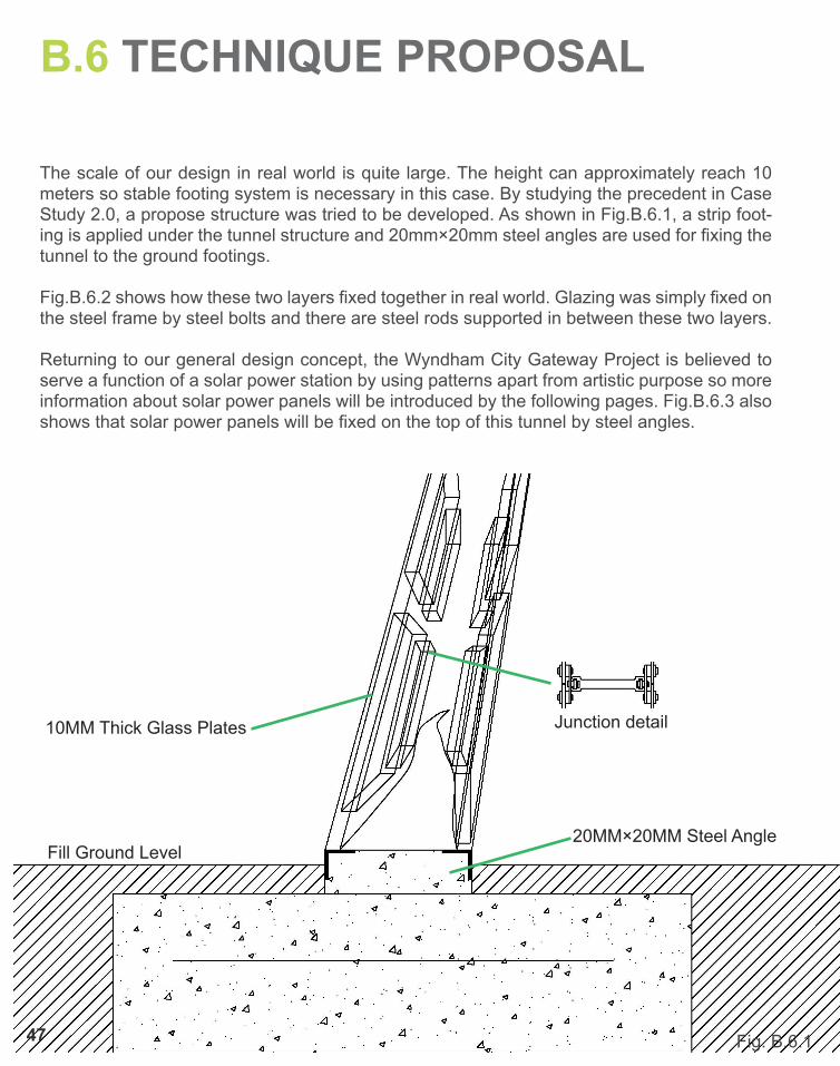
The scale of our design in real world is quite large. The height can approximately reach 10 meters so stable footing system is necessary in this case. By studying the precedent in Case Study 2.0, a propose structure was tried to be developed. As shown in Fig.B.6.1, a strip foot-ing is applied under the tunnel structure and 20mm×20mm steel angles are used for fixing the tunnel to the ground footings.
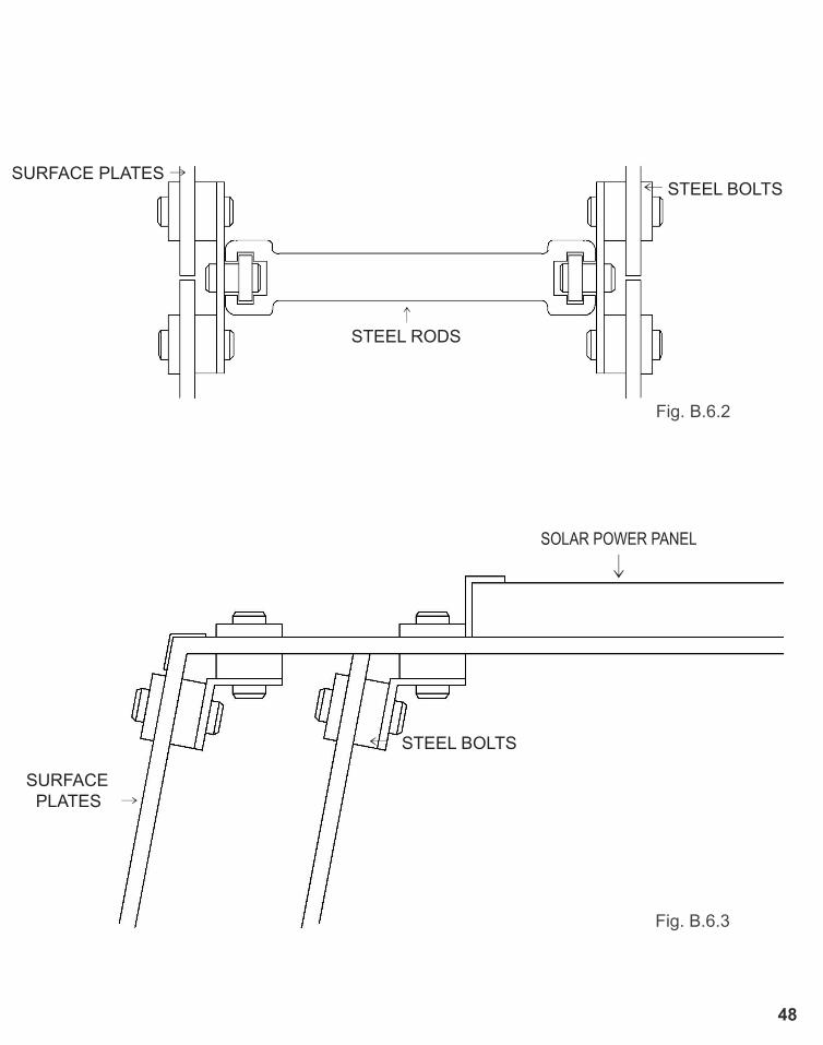
Fig.B.6.2 shows how these two layers fixed together in real world. Glazing was simply fixed on the steel frame by steel bolts and there are steel rods supported in between these two layers.
Returning to our general design concept, the Wyndham City Gateway Project is believed to serve a function of a solar power station by using patterns apart from artistic purpose so more information about solar power panels will be introduced by the following pages. Fig.B.6.3 also shows that solar power panels will be fixed on the top of this tunnel by steel angles.
SURFACE PLATES →← STEEL BOLTS
↑STEEL RODS
SOLAR POWER PANEL
↓
SURFACE PLATES →
← STEEL BOLTS
48 Fig. B.6.1
Fig. B.6.2
Fig. B.6.3
49
SOLAR POWER PANEL DETAILS
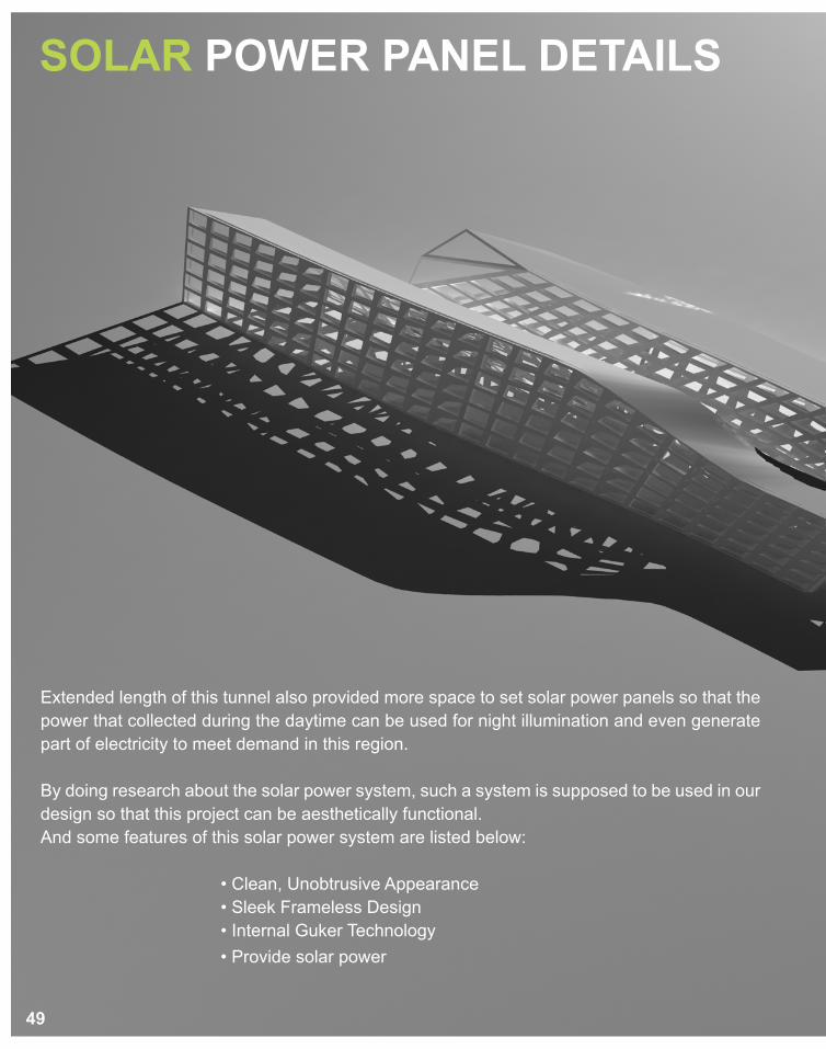
Extended length of this tunnel also provided more space to set solar power panels so that the power that collected during the daytime can be used for night illumination and even generate part of electricity to meet demand in this region.
By doing research about the solar power system, such a system is supposed to be used in our design so that this project can be aesthetically functional. And some features of this solar power system are listed below:
• Clean, Unobtrusive Appearance • Sleek Frameless Design • Internal Guker Technology • Provide solar power
50
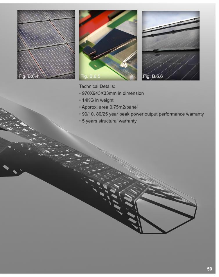
Technical Details:• 970X943X33mm in dimension• 14KG in weight• Approx. area 0.75m2/panel• 90/10, 80/25 year peak power output performance warranty• 5 years structural warranty
Fig. B.6.4 Fig. B.6.5 Fig. B.6.6
B.7 ALGORITHMIC SKETCHES
51
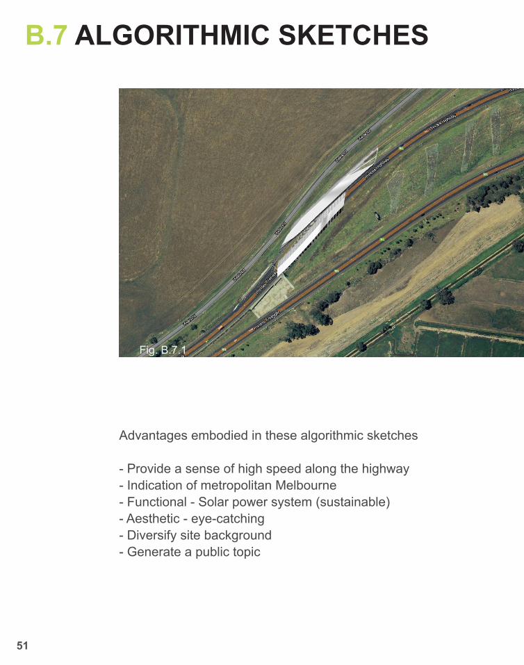
Fig. B.7.1
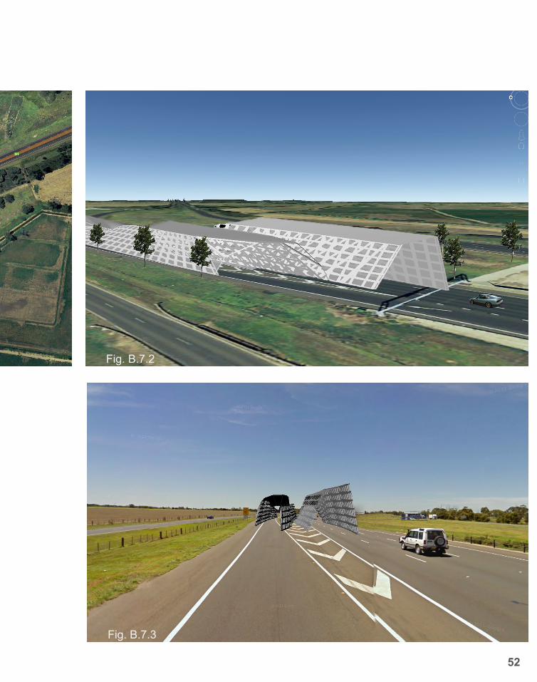
Advantages embodied in these algorithmic sketches
- Provide a sense of high speed along the highway- Indication of metropolitan Melbourne- Functional - Solar power system (sustainable)- Aesthetic - eye-catching- Diversify site background- Generate a public topic
52
Fig. B.7.2
Fig. B.7.3
B.8 LEARNING OBJECTIVES AND OUTCOMES
53
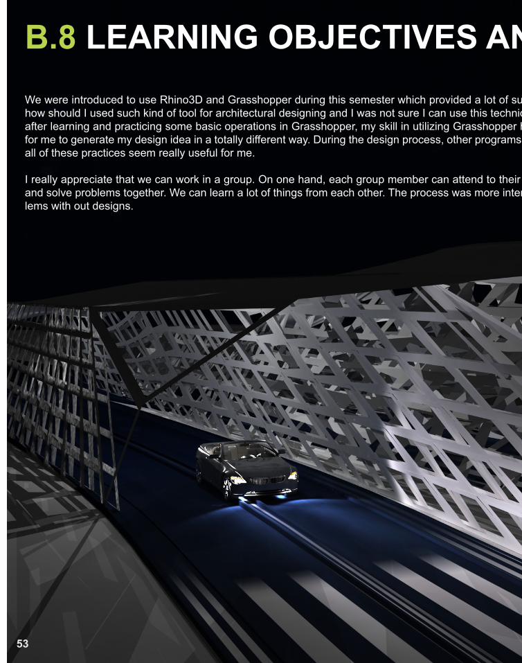
We were introduced to use Rhino3D and Grasshopper during this semester which provided a lot of surprise for me. Firstly I was really confused about how should I used such kind of tool for architectural designing and I was not sure I can use this technique to generate some design outcomes however after learning and practicing some basic operations in Grasshopper, my skill in utilizing Grasshopper has improved gradually. It provided opportunities for me to generate my design idea in a totally different way. During the design process, other programs were also applied such as InDesign, Photoshop, all of these practices seem really useful for me.
I really appreciate that we can work in a group. On one hand, each group member can attend to their own duties; on the other hand, we can generate and solve problems together. We can learn a lot of things from each other. The process was more interesting though we still have many technical prob-lems with out designs.
B.8 LEARNING OBJECTIVES AND OUTCOMES
54
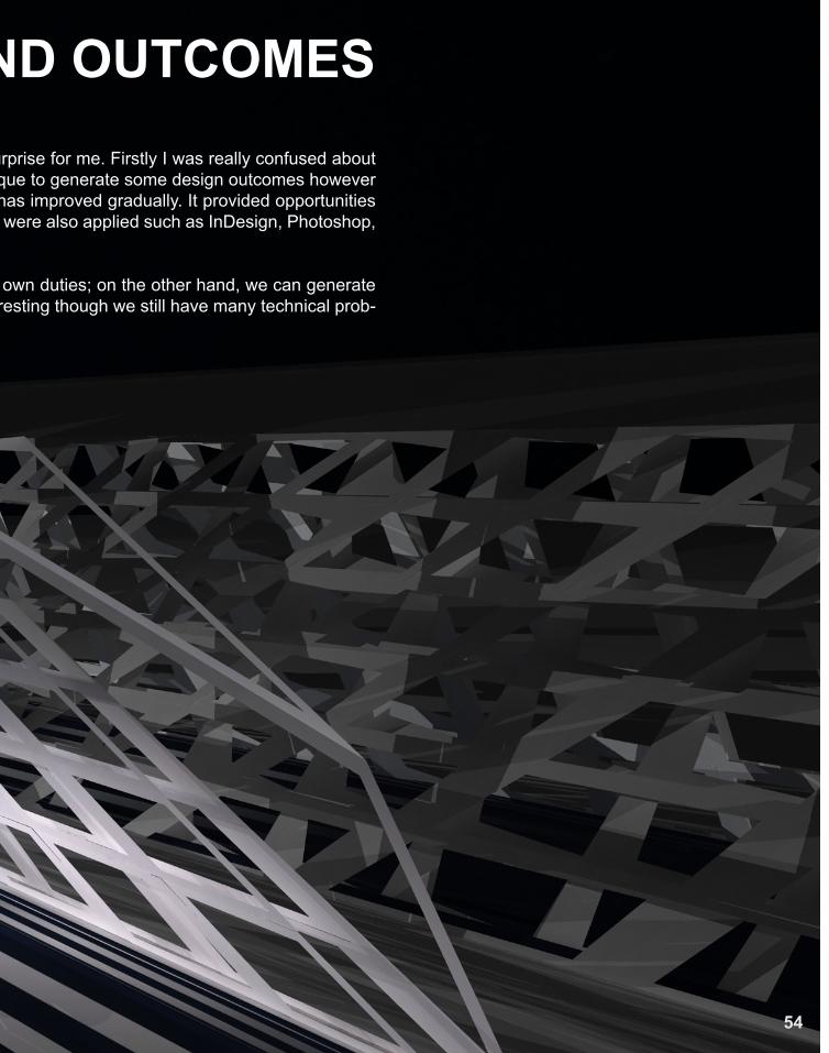
We were introduced to use Rhino3D and Grasshopper during this semester which provided a lot of surprise for me. Firstly I was really confused about how should I used such kind of tool for architectural designing and I was not sure I can use this technique to generate some design outcomes however after learning and practicing some basic operations in Grasshopper, my skill in utilizing Grasshopper has improved gradually. It provided opportunities for me to generate my design idea in a totally different way. During the design process, other programs were also applied such as InDesign, Photoshop, all of these practices seem really useful for me.
I really appreciate that we can work in a group. On one hand, each group member can attend to their own duties; on the other hand, we can generate and solve problems together. We can learn a lot of things from each other. The process was more interesting though we still have many technical prob-lems with out designs.
55

REFERENCE- http://www.e-architect.co.uk/china/sinosteel_international_plaza_tianjin.htm
- Fig.B.1.1, LMS resource
- Fig.B.1.2 - 4 http://www.itsliquid.com/mad-sinosteel.html
- Fig.B.2.1 - 3 http://www.stylepark.com/en/ceramica-cumella/facade-covering-spanish-expo-pavilion-aichi-japan
- Fig.B.3.1 - 7 http://www.architecture-buildings.com/post/acoustic-barrier-in-utrecht-the-netherlands-by-onl-ar
chitect/
- Fig.B.5.2 - 12 Photos taken by group 2
- Fig.B.5.6 Form from Fab Lab, http://edsc.unimelb.edu.au/fab-lab
- Fig.B.6.4 - 6 http://www.energymatters.com.au/renewable-energy/solar-power/
- Fig.B.7.1 - 3 Pictures rended based on the photos provied on LMS system
56


