Embed Size (px)
Citation preview
Max LChairm RegulaBecharBijan AAmde James Bruce RonaldChristiRicharFrank David RusselJim BrMario RobertJohn CJames RobertGeorgeNic CuTerry MGerald
AssociGhassaWilliamYigit BDean BJohn BKevin I. KwaCharleJames WalterM. Ari SYNOThis Sp602-02controsome Specifiprovisi RSpecifigreatethe proare thoof this
1 Recor
2 Aspri
Commentary on Specification for Masonry Structures (ACI 530.1-02/ASCE 6-02/TMS 602-02)
Reported by the Masonry Standards Joint Committee (MSJC)
. Porter an
Donald G. McMican Vice Chairman
J. Gregg Borchelt Secretary
Jason J. Thompson Membership Secretary
r Members1: a E. Abboud hmadi
M. Amde E. Amrhein Barnes E. Barnett ne Beall d M. Bennett Berg T. Biggs l H. Brown yja J. Catani N. Chittenden hrysler Colville W. Crooks E. Crow III oco . Curtis
A. Dalrymple
Howard L. Droz Jeffrey L. Elder Richard C. Felice Richard Filloramo Russell T. Flynn Fouad H. Fouad John A. Frauenhoffer Thomas A. Gangel Hans R. Ganz David C. Gastgeb Stephen H. Getz Satyendra K. Ghosh Edgar F. Glock Jr. Clayford T. Grimm H. R. Hamilton III R. Craig Henderson Kurt R. Hoigard Thomas A. Holm Ronald J. Hunsicker Rochelle C. Jaffe Rashod R. Johnson
Eric N. Johnson John C. Kariotis Jon P. Kiland Richard E. Klingner L. Donald Leinweber Hugh C. MacDonald Jr. John H. Matthys Robert McCluer W. Mark McGinley John Melander George A. Miller Reg Miller Vilas Mujumdar Colin C. Munro W. Thomas Munsell Javeed A. Munshi Antonio Nanni Robert L. Nelson Joseph F. Neussendorfer James L. Nicholos Gary G. Nichols
Jerry M. Painter Keith G. Peetz Joseph E. Saliba Michael P. Schuller Richard C. Schumacher Daniel Shapiro Michael J. Tate Itzhak Tepper Margaret Thomson Diane Throop Robert E. VanLaningham Donald W. Vannoy Brian J. Walker Scott W. Walkowicz Terence A. Weigel A. Rhett Whitlock Joseph A. Wintz III Thomas D. Wright R. Dale Yarbrough Daniel Zechmeister
ate Members2: n Al-Chaar G. Bailey
ozkurt rown ufford D. Callahan ng Chang s B. Clark Jr. W. Cowie L. Dickey f Fazil
Christopher L. Galitz David Giambrone Dennis W. Graber Jeffrey H. Greenwald B. A. Haseltine Barbara G. Heller A. W. Hendry Thomas F. Herrell Paul Hobelman Jason Ingham Fred A. Kinateder
Mervyn K. Kowalsky Norbert Krogstad Peter T. Laursen Steve Lawrence Michael D. Lewis Nicholas T. Loomis Robert F. Mast Raul Alamo Neidhart Steven E. O’Hara Rick Okawa Adrian W. Page
Ronald Sandy Pringle Ruiz Lopez M. Rafael Roscoe Reeves Jr. Paul G. Scott Christine A. Subasic Narendra Taly John G. Tawresey Robert Thomas Dean J. Tills Michael G. Verlaque William A. Wood
PSIS ecification for Masonry Structures (ACI 530.1-02/ASCE 6-02/TMS ) is written as a master specification and is required by the Code to l materials, labor, and construction. This commentary discusses of the considerations of the committee in developing this cation with emphasis given to the explanation of new or revised ons that may be unfamiliar to code users. eferences to much of the research data used to prepare this cation are cited for the user desiring to study individual items in r detail. Other documents that provide suggestions for carrying out visions of this Specification are also cited. The subjects covered se found in this Specification. The chapter and article numbering Specification are followed throughout.
gular members fully participate in Committee activities, including responding to respondence and voting. sociate members monitor Committee activities, but do not have voting vileges.
Keywords: clay brick; concrete block; construction; construction materials; curing; glass unit masonry; grout; grouting; inspection; joints; masonry; materials handling; mortars (material and placement); prestressed masonry; quality assurance and quality control; reinforcing steel; specifications; tests; tolerances; veneer (anchored and adhered). This Commentary is intended for guidance in designing, planning, executing, or inspecting construction and in preparing specifications. References to this document should not be made in the Project Documents. If items found in this document are desired to be a part of the Project Documents, they should be phrased in mandatory language and incorporated into the Project Documents. SI equivalents shown in this document are calculated conversions. Equations are based on U.S. Customary (in.-lb) Units.
SC-2 MANUAL OF CONCRETE PRACTICE
CONTENTS INTRODUCTION, pg. SC-3 PART 1 — GENERAL, pg. SC-4
1.1 — Summary ........................................................................................................................................SC-4 1.2 — Definitions .....................................................................................................................................SC-4 1.3 — References .....................................................................................................................................SC-4 1.4 — System description .........................................................................................................................SC-4 1.5 — Submittals ......................................................................................................................................SC-6 1.6 — Quality assurance ...........................................................................................................................SC-7 1.7 — Delivery, storage, and handling .....................................................................................................SC-7 1.8 — Project conditions ..........................................................................................................................SC-7 References ................................................................................................................................................SC-8
PART 2 — PRODUCTS, pg. SC-10
2.1 — Mortar materials ..........................................................................................................................SC-10 2.2 — Grout materials ............................................................................................................................SC-10 2.3 — Masonry unit materials ................................................................................................................SC-11 2.4 — Reinforcement, prestressing tendons, and metal accessories .......................................................SC-12 2.5 — Accessories ..................................................................................................................................SC-15 2.6 — Mixing .........................................................................................................................................SC-16 2.7 — Fabrication ...................................................................................................................................SC-16 References ..............................................................................................................................................SC-17
PART 3 — EXECUTION, pg. SC-18
3.1 — Inspection ....................................................................................................................................SC-18 3.2 — Preparation ..................................................................................................................................SC-18 3.3 — Masonry erection .........................................................................................................................SC-18 3.4 — Reinforcement, tie, and anchor installation .................................................................................SC-19 3.5 — Grout placement ..........................................................................................................................SC-19 3.6 — Prestressing tendon installation and stressing procedure .............................................................SC-21 3.7 — Field quality control ....................................................................................................................SC-21 References ...............................................................................................................................................SC-21
COMMENTARY ON SPECIFICATION FOR MASONRY STRUCTURES SC-3
INTRODUCTION
Chapter 1 of the “Building Code Requirements for Masonry Structures (ACI 530-02/ASCE 5-02/TMS 402-02)” makes the “Specification for Masonry Structures (ACI 530.1-02/ASCE 6-02/TMS 602-02)” an integral part of the Code. ACI 530.1/ASCE 6/TMS 602 Specification sets minimum construction requirements regarding the materials used in and the erection of masonry structures. Specifications are written to set minimum acceptable levels of performance for the contractor. This commentary is directed to the architect/engineer writing the project specifications. This commentary covers some of the points the Masonry Standards Joint Committee (MSJC) considered in developing the provisions of the Code which are written into this Specification. Further explanation and documentation of some of the provisions of this Specification are included. Comments on specific provisions are made under the corresponding part or section and article numbers of this Code and Specification. As stated in the Foreword, Specification ACI 530.1/ASCE 6/TMS 602 is a reference standard which
the architect/engineer may cite in the contract documents for any project. Owners, through their representatives (architect/engineer), may write requirements into contract documents that are more stringent than those of ACI 530.1/ASCE 6/TMS 602. This can be accomplished with supplemental specifications to this Specification. The contractor should not be asked through contract documents to comply with the Code or to assume responsibility regarding design (Code) requirements. The Code is not intended to be made a part of the contract documents. The Foreword and Preface to the Checklists contain information that explains the function and use of this Specification. The Checklists are a summary of the Articles that require a decision by the architect/engineer preparing the contract documents. Project specifications should include those items called out in the Checklists that are pertinent to the project. All projects will require response to the mandatory requirements.
SC-4 MANUAL OF CONCRETE PRACTICE
PART 1 — GENERAL
1.1 — Summary 1.1 C The scope of the work to be completed under this section of the contract documents is outlined. All of these tasks and materials will not appear in every project. 1.2 — Definitions For consistent application of this Specification, it is necessary to define terms which have particular meaning in this Specification. The definitions given are for use in application of this Specification only and do not always correspond to ordinary usage. The definition of the same term has been coordinated between the Code and Specification. The permitted tolerances for units are found in the appropriate materials standards. Permitted tolerances for joints and masonry construction are found in this Specification. Nominal dimensions are usually used to identify the size of a masonry unit. The thickness or width is given first, followed by height and length. Nominal dimensions are normally given in whole numbers nearest to the specified dimensions. Specified dimensions are most often used for design calculations. 1.3 — References This list of standards includes material specifications, sampling, test methods, detailing requirements, design procedures and classifications. Standards produced by the American Society for Testing and Materials (ASTM) are referenced whenever possible. Material manufacturers and testing laboratories are familiar with ASTM standards which are the result of a consensus process. In the few cases not covered by existing standards, the committee generated its own requirements. Specific dates are given since changes to the standards alter this Specification. Many of these standards require compliance with additional standards. 1.4 — System description 1.4 A Compressive strength requirements — Design is based on a certain f ′m and this compressive strength value must be achieved or exceeded. In a multiwythe wall designed as a composite wall, the compressive strength of masonry for each wythe or grouted collar joint must equal or exceed f ′m .
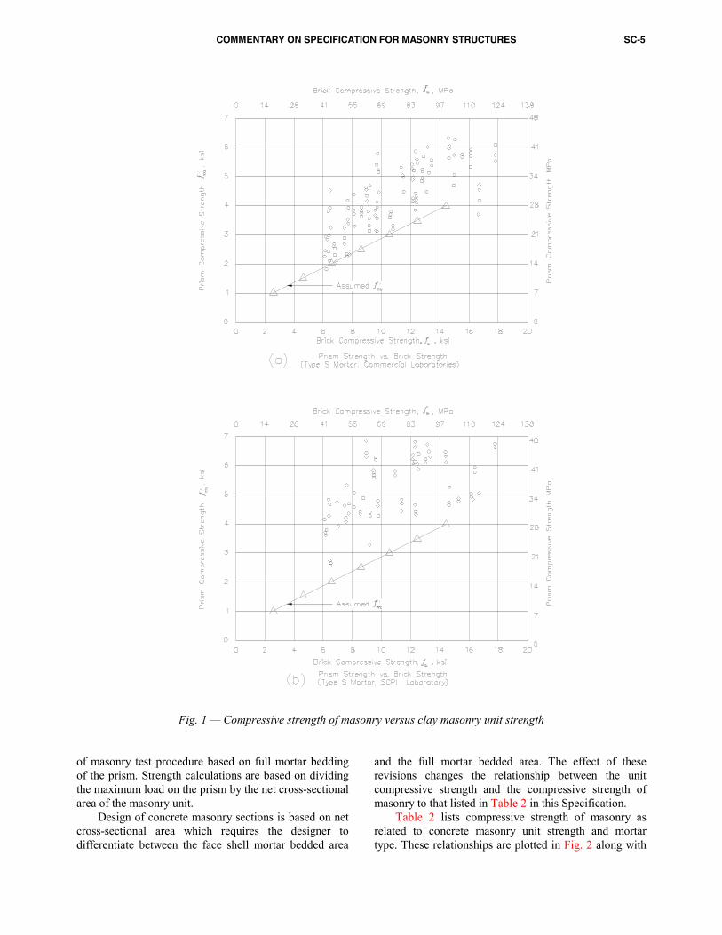
1.4 B Compressive strength determination 1.4 B.1 There are two separate means of determining the compressive strength of masonry. The unit strength method eliminates the expense of prism tests but is more conservative than the prism test method. The unit strength method was generated by using prism test data as shown in Figs. 1 and 2. When the method is not specified by the architect or engineer, the
Specification permits the contractor to select the method of determining the compressive strength of masonry.
1.4 B.2 Unit strength method — Compliance with the requirement for f ′m based on the compressive strength of masonry units, grout, and mortar type is permitted in lieu of prism testing. The influence of mortar joint thickness is noted by the maximum joint thickness. Grout strength greater than or equal to f ′m fulfills the requirements of Specification Article 1.4 A and Code Section 1.14.7.1. 1.4 B.2.a Clay masonry — The values of net area compressive strength of clay masonry in Table 1 were derived using the following equation taken from Reference 1.1:′ = +f A B fm u( )400 where
A = 1 (inspected masonry) B = 0.2 for Type N portland cement-lime
mortar, 0.25 for Type S or M portland cement-lime mortar
fu = average compressive strength of brick, psi f ′m = specified compressive strength of masonry
Rearranging terms and letting A = 1.0
f fBu
m= ′ − 400
(These equations are for inch-pound units only.)
These values were based on testing of solid clay masonry units1.1 and portland cement-lime mortar. Further testing1.2 has shown that the values are applicable for hollow clay masonry units and for both types of units with all mortar types. A plot of the data is shown in Fig. 1. Reference 1.1 uses a height-to-thickness ratio of five as a basis to establish prism compressive strength. The Code uses a different method to design for axial stress so it was necessary to change the basic prism h/t ratio to two. This corresponds to the h/t ratio used for concrete masonry in the Code and for all masonry in other codes. The net effect is to increase the net area compressive strength of brick masonry by 22 percent over that in Reference 1.1. 1.4 B.2.b Concrete masonry — In building codes1.3, 1.4 prior to the Code, the compressive strength of concrete masonry was based on the net cross-sectional area of the masonry unit regardless of whether the prism was constructed using full or face shell mortar bedding. Furthermore, in these previous codes, the designer was required to base axial stress calculations on the net area of the unit regardless of the type of mortar bedding used. The Code has developed a standard compressive strength
COMMENTARY ON SPECIFICATION FOR MASONRY STRUCTURES SC-5
Fig. 1 — Compressive strength of masonry versus clay masonry unit strengthof masonry test procedure based on full mortar bedding of the prism. Strength calculations are based on dividing the maximum load on the prism by the net cross-sectional area of the masonry unit. Design of concrete masonry sections is based on net cross-sectional area which requires the designer to differentiate between the face shell mortar bedded area
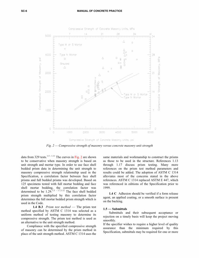
and the full mortar bedded area. The effect of these revisions changes the relationship between the unit compressive strength and the compressive strength of masonry to that listed in Table 2 in this Specification. Table 2 lists compressive strength of masonry as related to concrete masonry unit strength and mortar type. These relationships are plotted in Fig. 2 along with
SC-6 MANUAL OF CONCRETE PRACTICE
Fig. 2 — Compressive strength of masonry versus concrete masonry unit strengthdata from 329 tests.1.5 - 1.11 The curves in Fig. 2 are shown to be conservative when masonry strength is based on unit strength and mortar type. In order to use face shell bedded prism data in determining the unit strength to masonry compressive strength relationship used in the Specification, a correlation factor between face shell prisms and full bedded prisms was developed. Based on 125 specimens tested with full mortar bedding and face shell mortar bedding, the correlation factor was determined to be 1.29.1.5 - 1.7,1.12 The face shell bedded prism strength multiplied by this correlation factor determines the full mortar bedded prism strength which is used in the Code. 1.4 B.3 Prism test method — The prism test method specified by ASTM C 1314 was selected as a uniform method of testing masonry to determine its compressive strength. The prism test method is used as an alternative to the unit strength method. Compliance with the specified compressive strength of masonry can be determined by the prism method in place of the unit strength method. ASTM C 1314 uses the
same materials and workmanship to construct the prisms as those to be used in the structure. References 1.13 through 1.17 discuss prism testing. Many more references on the prism test method parameters and results could be added. The adoption of ASTM C 1314 alleviates most of the concerns stated in the above references. ASTM C 1314 replaced ASTM E 447, which was referenced in editions of the Specification prior to 1999.
1.4 C Adhesion should be verified if a form release agent, an applied coating, or a smooth surface is present on the backing. 1.5 — Submittals Submittals and their subsequent acceptance or rejection on a timely basis will keep the project moving smoothly. If the specifier wishes to require a higher level of quality assurance than the minimum required by this Specification, submittals may be required for one or more
COMMENTARY ON SPECIFICATION FOR MASONRY STRUCTURES SC-7
of the following: shop drawings for reinforced masonry and lintels; sample specimens of masonry units, colored mortar, each type of movement joint accessory, anchor, tie, fastener, and metal accessory; and test results for masonry units, mortar, and grout. 1.6 — Quality assurance
Quality assurance consists of the actions taken by an owner or owner’s representative, including establishing the quality assurance requirements, to provide assurance that materials and workmanship are in accordance with the contract documents. Quality assurance includes quality control measures as well as testing and inspection to verify compliance. The term quality control was not used in the Specification because its meaning varies with the perspective of the parties involved in the project.
The owner and architect/engineer may require a testing laboratory to provide some or all of the tests mentioned. See also the Commentary for Article 1.4.
The quality objectives will be met when the building is properly designed, completed using materials complying with product specifications using adequate construction practices, and is adequately maintained.
Laboratories that comply with the requirements of ASTM C 1093 are more likely to be familiar with masonry materials and testing. Specifying that the testing agencies comply with the requirements of ASTM C 1093 should improve the quality of the resulting masonry.
1.6 B The Code and this Specification require that all masonry be inspected. The allowable stresses used in the Code are based on the premise that the work will be inspected, and that quality assurance measures will be implemented. Minimum testing and minimum inspection requirements are given in Specification Tables 3, 4, and 5. The architect/engineer may increase the amount of testing and inspection required. The method of payment for inspection services is usually handled in general conditions or other contract documents and usually will not be handled by this article.
1.6 C The contractor establishes mix designs, the source for supply of materials, and suggests change orders. The listing of duties of the inspection agency, testing agency, and contractor provide for a coordination of their tasks and a means of reporting results. The contractor is bound by contract to supply and place the materials called for in the contract documents. Perfection is obviously the goal, but factors of safety included in the design method recognize that some deviation from perfection will exist. Engineering judgment must be used to evaluate reported deficiencies. Items that influence structural performance are controlled by the dimensional tolerances of Specification Article 3.3G.
1.6 D Sample panels should contain the full range of unit and mortar color. All procedures, including cleaning and application of coatings and sealants, should be carried out on the sample panel. The effect of these materials and procedures on the masonry can then be determined before large areas are treated. Since it serves as a comparison of the finished work, the sample panel should be maintained until all work has been accepted. The specifier has the option of permitting a segment of the masonry construction to serve as a sample panel or requiring a separate stand-alone panel. 1.7 — Delivery, storage and handling The performance of masonry materials can be lessened by contamination by dirt, water and other materials during delivery or at the jobsite. Reinforcement and metal accessories are less prone to problems from handling than masonry materials. 1.8 — Project conditions 1.8 C Cold weather construction — The procedure described in this article represents the committee’s consensus of current good construction practice and has been framed to generally agree with masonry industry recommendations.1.18 The provisions of Article 1.8 C are mandatory, even if the procedures submitted under Article 1.5 B.3.a are not required. The contractor has several options to achieve the results required in Article 1.8 C. The options are available because of the climatic extremes and their duration. When the air temperature at the jobsite or unit temperatures fall below 40º F (4.4º C), the cold weather protection plan submitted becomes mandatory. Work stoppage may be justified if a short cold spell is anticipated. Enclosures and heaters can be used as necessary. Temperature of the masonry mortar may be measured using a metal tip immersion thermometer inserted into a sample of the mortar. The mortar sample may be mortar as contained in the mixer, in hoppers for transfer to the working face of the masonry or as available on mortar boards currently being used. The critical mortar temperatures are the temperatures as sensed at the mixer and mortar board locations. The ideal mortar temperature is 60º F to 80º F (15.6º C to 26.7º C). Temperature of the masonry unit may be measured using a metallic surface contact thermometer. The contractor may choose to enclose the entire area rather than make the sequential materials conditioning and protection modifications. Ambient temperature conditions apply while work is in progress. Minimum daily temperatures apply to the time after grouted masonry is placed. Mean daily temperatures apply to the time after ungrouted masonry is placed. Grout made with Type III portland cement gains strength more quickly than grout mixed with Type I
SC-8 MANUAL OF CONCRETE PRACTICE
portland cement. This faster strength gain eliminates the need to protect masonry for the additional 24 hr period.
1.8 D Hot weather construction — As temperature increases, the relative humidity at the masonry surface decreases and the evaporation rate increases. These conditions can lead to dryout of the mortar and grout.1.19 Dryout adversely affects the properties of mortar and grout because dryout signals improper curing and associated reduction of masonry strength development. The preparation, construction, and protection requirements in the Specification are minimum requirements to avoid dryout of mortar and grout and to allow for proper curing. They are based on industry practice.1.20 - 1.22 More stringent and extensive hot weather practices may be prudent where temperatures are high, winds are strong, and humidity is low.
During hot weather, shading masonry materials and equipment reduces mortar and grout temperatures. Scheduling construction to avoid hotter periods of the day should be considered.
See Specification Commentary Article 2.1 for considerations in selecting mortar materials. The most effective way of reducing mortar and grout batch temperatures is by using cool mixing water. Small batches of mortar are preferred over larger batches to minimize drying time on mortar boards. Mortar should not be used after a maximum of 2 hr after initial mixing in hot weather conditions. Retempering with cool water will restore plasticity and reduce the mortar temperature.
Most mason’s sand is delivered to the project in a damp, loose condition with a moisture content of about 4 to 6 percent. Sand piles should be kept cool and in a damp, loose condition by sprinkling and by covering with a plastic sheet to limit evaporation.
Research suggests that covering and moist curing of concrete masonry walls dramatically improves flexural bond strength over walls not covered nor moist cured.1.23 References 1.1. “Recommended Practice for Engineered Brick Masonry,” Brick Institute of America (formerly Structural Clay Products Association), Reston, VA, 1969. 1.2. Brown, R.H., and Borchelt, J.G., “Compression Tests of Hollow Brick Units and Prisms,” Masonry Components to Assemblages, ASTM STP 1063, J.H. Matthys, editor, American Society for Testing and Materials, Philadelphia, PA, 1990, pp. 263 - 278. 1.3. ACI Committee 531, Building Code Requirements for Concrete Masonry Structures (ACI 531-79) (Revised 1983)," American Concrete Institute, Detroit, MI, 1983, 20 pp. 1.4. “Specification for the Design and Construction of Load Bearing Concrete Masonry,” (TR-75B), National Concrete Masonry Association, Herndon, VA, 1976.
1.5. Redmond, T.B., “Compressive Strength of Load Bearing Concrete Masonry Prisms,” National Concrete Masonry Association Laboratory Tests, Herndon, VA, 1970, Unpublished. 1.6. Nacos, C.J., “Comparison of Fully Bedded and Face-Shell Bedded Concrete Block,” Report No. CE-495, Colorado State University, Fort Collins, CO, 1980, Appendix p. A-3. 1.7. Maurenbrecher, A.H.P., “Effect of Test Procedures on Compressive Strength of Masonry Prisms,” Proceedings, 2nd Canadian Masonry Symposium, Carleton University, Ottawa, June 1980, pp. 119-132. 1.8. Self, M.W., “Structural Properties of Loading Bearing Concrete Masonry,” Masonry: Past and Present, STP-589, ASTM, Philadelphia, PA, 1975, Table 8, p. 245. 1.9. Baussan, R., and Meyer, C., “Concrete Block Masonry Test Program,” Columbia University, New York, NY, 1985. 1.10. Seaman, J.C., “Investigation of the Structural Properties of Reinforced Concrete Masonry,” National Concrete Masonry Association, Herndon, VA, 1955. 1.11. Hamid, A.A., Drysdale, R.G., and Heidebrecht, A.C., “Effect of Grouting on the Strength Characteristics of Concrete Block Masonry,” Proceedings, North American Masonry Conference, University of Colorado, Boulder, CO, Aug. 1978, pp. 11-1 through 11-17. 1.12. Hatzinikolas, M., Longworth, J., and Warwaruk, J., “The Effect of Joint Reinforcement on Vertical Load Carrying Capacity of Hollow Concrete Block Masonry,” Proceedings, North American Masonry Conference, University of Colorado, Boulder, CO, Aug. 1978. 1.13. Atkinson, R.H., and Kingsley, G.R., “A Comparison of the Behavior of Clay and Concrete Masonry in Compression,” Atkinson-Noland & Associates, Inc., Boulder, CO, Sept. 1985. 1.14. Priestley, M.J.N., and Elder, D.M., “Stress-Strain Curves for Unconfined and Confined Concrete Masonry,” ACI JOURNAL, Proceedings V. 80, No. 3, Detroit, MI, May-June 1983, pp. 192-201. 1.15. Miller, D.E.; Noland, J.L.; and Feng, C.C., “Factors Influencing the Compressive Strength of Hollow Clay Unit Prisms,” Proceedings, 5th International Brick Masonry Conference, Washington DC, 1979. 1.16. Noland, J.L., “Proposed Test Method for Determining Compressive Strength of Clay-Unit Prisms,” Atkinson-Noland & Associates, Inc., Boulder, CO, June 1982. 1.17. Hegemier, G.A., Krishnamoorthy, G., Nunn, R.O., and Moorthy, T.V., “Prism Tests for the Compressive Strength of Concrete Masonry,” Proceedings, North American Masonry Conference, University of Colorado, Boulder, CO, Aug. 1978, pp. 18-1 through 18-17.

COMMENTARY ON SPECIFICATION FOR MASONRY STRUCTURES SC-9
1.18. “Recommended Practices and Guide Specifications for Cold Weather Masonry Construction,” International Masonry Industry All-Weather Council, Washington, DC, 1973.
1.19. Tomasetti, A.A., “Problems and Cures in Masonry” ASTM STP 1063, Masonry Components to Assemblages, ASTM, Philadelphia. PA ,1990, 324-338.
1.20. “All Weather Construction” Technical Notes on Brick Construction Number 1 Revised, Brick Institute of America, Reston, VA, March 1992
1.21. “Hot Weather Masonry Construction,” Trowel Tips, Portland Cement Association, Skokie, IL, 1993
1.22. Panarese, W.C., S.H. Kosmatka, and F.A. Randall Jr “Concrete Masonry Handbook for Architects, Engineers, and Builders,” Portland Cement Association, Skokie, IL, 1991, pp. 121-123.
1.23. “Research Evaluation of Flexural Tensile Strength of Concrete Masonry,” National Concrete Masonry Association, Herndon, VA, 1994.
SC-10 MANUAL OF CONCRETE PRACTICE
PART 2 — PRODUCTS
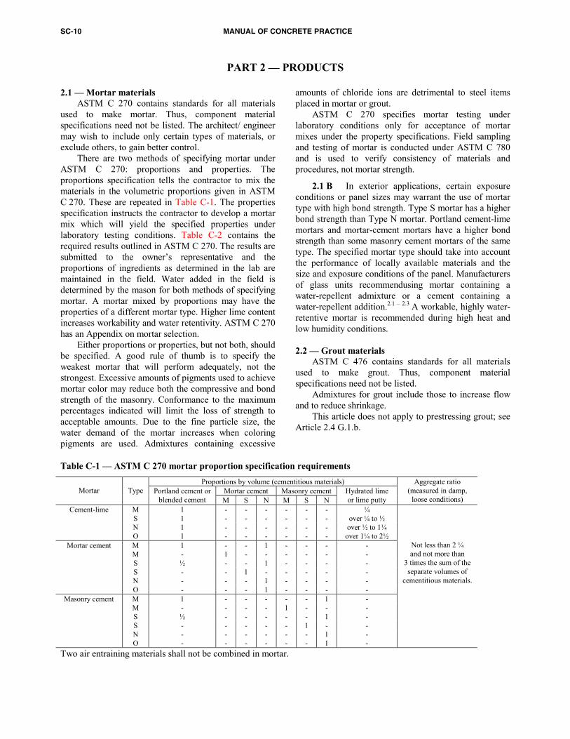
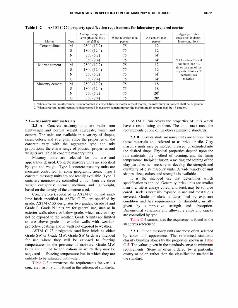
2.1 — Mortar materials ASTM C 270 contains standards for all materials used to make mortar. Thus, component material specifications need not be listed. The architect/ engineer may wish to include only certain types of materials, or exclude others, to gain better control. There are two methods of specifying mortar under ASTM C 270: proportions and properties. The proportions specification tells the contractor to mix the materials in the volumetric proportions given in ASTM C 270. These are repeated in Table C-1. The properties specification instructs the contractor to develop a mortar mix which will yield the specified properties under laboratory testing conditions. Table C-2 contains the required results outlined in ASTM C 270. The results are submitted to the owner’s representative and the proportions of ingredients as determined in the lab are maintained in the field. Water added in the field is determined by the mason for both methods of specifying mortar. A mortar mixed by proportions may have the properties of a different mortar type. Higher lime content increases workability and water retentivity. ASTM C 270 has an Appendix on mortar selection. Table C-1 — ASTM C 270 mortar proportion specification requirementsProportions by volume (cementitious materials) Mortar cement Masonry cement
Mortar
Type Portland cement or
blended cement M S N M S N Hydrated lime or lime putty
Aggregate ratio (measured in damp,
loose conditions) Cement-lime M 1 - - - - - - ¼
S 1 - - - - - - over ¼ to ½ N 1 - - - - - - over ½ to 1¼ O 1 - - - - - - over 1¼ to 2½
Mortar cement M 1 - - 1 - - - - M - 1 - - - - - - S ½ - - 1 - - - - S - - 1 - - - - - N - - - 1 - - - - O - - - 1 - - - -
Masonry cement M 1 - - - - - 1 - M - - - - 1 - - - S ½ - - - - - 1 - S - - - - - 1 - - N - - - - - - 1 - O - - - - - - 1 -
Not less than 2 ¼ and not more than
3 times the sum of the separate volumes of
cementitious materials.
Two air entraining materials shall not be combined in mortar.
Either proportions or properties, but not both, should be specified. A good rule of thumb is to specify the weakest mortar that will perform adequately, not the strongest. Excessive amounts of pigments used to achieve mortar color may reduce both the compressive and bond strength of the masonry. Conformance to the maximum percentages indicated will limit the loss of strength to acceptable amounts. Due to the fine particle size, the water demand of the mortar increases when coloring pigments are used. Admixtures containing excessive
amounts of chloride ions are detrimental to steel items placed in mortar or grout. ASTM C 270 specifies mortar testing under laboratory conditions only for acceptance of mortar mixes under the property specifications. Field sampling and testing of mortar is conducted under ASTM C 780 and is used to verify consistency of materials and procedures, not mortar strength.
2.1 B In exterior applications, certain exposure conditions or panel sizes may warrant the use of mortar type with high bond strength. Type S mortar has a higher bond strength than Type N mortar. Portland cement-lime mortars and mortar-cement mortars have a higher bond strength than some masonry cement mortars of the same type. The specified mortar type should take into account the performance of locally available materials and the size and exposure conditions of the panel. Manufacturers of glass units recommendusing mortar containing a water-repellent admixture or a cement containing a water-repellent addition.2.1 – 2.3 A workable, highly water-retentive mortar is recommended during high heat and low humidity conditions. 2.2 — Grout materials ASTM C 476 contains standards for all materials used to make grout. Thus, component material specifications need not be listed. Admixtures for grout include those to increase flow and to reduce shrinkage.
This article does not apply to prestressing grout; see Article 2.4 G.1.b.
COMMENTARY ON SPECIFICATION FOR MASONRY STRUCTURES SC-11
Table C-2 — ASTM C 270 property specification requirements for laboratory prepared mortar
Mortar
Type
Average compressive strength at 28 days,
psi (MPa)
Water retention min,
percent
Air content max,
percent
Aggregate ratio (measured in damp,
loose conditions) M 2500 (17.2) 75 12 S 1800 (12.4) 75 12 N 750 (5.2) 75 141
Cement-lime
O 350 (2.4) 75 141
M 2500 (17.2) 75 12 S 1800 (12.4) 75 12 N 750 (5.2) 75 141
Mortar cement
O 350 (2.4) 75 141 M 2500 (17.2) 75 18 S 1800 (12.4) 75 18 N 750 (5.2) 75 202
Masonry cement
O 350 (2.4) 75 202
Not less than 2¼ and not more than 3½
times the sum of the separate volumes of
cementitious materials
1 When structural reinforcement is incorporated in cement-lime or mortar cement mortar, the maximum air content shall be 12 percent. 2 When structural reinforcement is incorporated in masonry cement mortar, the maximum air content shall be 18 percent.
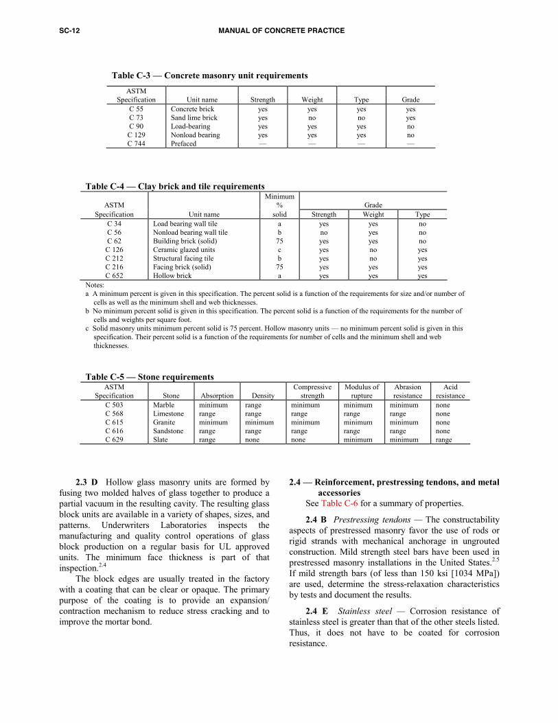
2.3 — Masonry unit materials 2.3 A Concrete masonry units are made from lightweight and normal weight aggregate, water and cement. The units are available in a variety of shapes, sizes, colors, and strengths. Since the properties of the concrete vary with the aggregate type and mix proportions, there is a range of physical properties and weights available in concrete masonry units. Masonry units are selected for the use and appearance desired. Concrete masonry units are specified by type and weight. Type I concrete masonry units are moisture controlled. In some geographic areas, Type I concrete masonry units are not readily available. Type II units are nonmoisture controlled units. There are three weight categories: normal, medium, and lightweight, based on the density of the concrete used.Concrete brick specified in ASTM C 55, and sand-lime brick specified in ASTM C 73, are specified by grade. ASTM C 55 designates two grades: Grade N and Grade S. Grade N units are for general use, such as in exterior walls above or below grade, which may or may not be exposed to the weather. Grade S units are limited to use above grade in exterior walls with weather-protective coatings and in walls not exposed to weather.
ASTM C 73 designates sand-lime brick as either Grade SW or Grade MW. Grade SW brick are intended for use where they will be exposed to freezing temperatures in the presence of moisture. Grade MW brick are limited to applications in which they may be subjected to freezing temperature but in which they are unlikely to be saturated with water. Table C-3 summarizes the requirements for various concrete masonry units found in the referenced standards.
ASTM C 744 covers the properties of units which have a resin facing on them. The units must meet the requirements of one of the other referenced standards.
2.3 B Clay or shale masonry units are formed from those materials and referred to as brick or tile. Clay masonry units may be molded, pressed, or extruded into the desired shape. Physical properties depend upon the raw materials, the method of forming, and the firing temperature. Incipient fusion, a melting and joining of the clay particles, is necessary to develop the strength and durability of clay masonry units. A wide variety of unit shapes, sizes, colors, and strengths is available. It is the intended use that determines which specification is applied. Generally, brick units are smaller than tile, tile is always cored, and brick may be solid or cored. Brick is normally exposed in use and most tile is covered. Grade or class is determined by exposure condition and has requirements for durability, usually given by compressive strength and absorption. Dimensional variations and allowable chips and cracks are controlled by type. Table C-4 summarizes the requirements found in the standards referenced.
2.3 C Stone masonry units are most often selected by color and appearance. The referenced standards classify building stones by the properties shown in Table C-5. The values given in the standards serve as minimum requirements. Stone is often ordered by a particular quarry or color, rather than the classification method in the standard.
SC-12 MANUAL OF CONCRETE PRACTICE
Table C-3 — Concrete masonry unit requirements ASTM
Specification Unit name Strength Weight Type Grade C 55 C 73 C 90
C 129 C 744
Concrete brick Sand lime brick Load-bearing Nonload bearing Prefaced
yes yes yes yes —
yes no yes yes —
yes no yes yes —
yes yes no no —
Table C-4 — Clay brick and tile requirements
ASTM Minimum
%
Grade Specification Unit name solid Strength Weight Type
C 34 C 56 C 62
C 126 C 212 C 216 C 652
Load bearing wall tile Nonload bearing wall tile Building brick (solid) Ceramic glazed units Structural facing tile Facing brick (solid) Hollow brick
a b
75 c b
75 a
yes no yes yes yes yes yes
yes yes yes no no yes yes
no no no yes yes yes yes
Notes: a A minimum percent is given in this specification. The percent solid is a function of the requirements for size and/or number of
cells as well as the minimum shell and web thicknesses. b No minimum percent solid is given in this specification. The percent solid is a function of the requirements for the number of
cells and weights per square foot. c Solid masonry units minimum percent solid is 75 percent. Hollow masonry units — no minimum percent solid is given in this
specification. Their percent solid is a function of the requirements for number of cells and the minimum shell and web thicknesses.
Table C-5 — Stone requirementsASTM Specification
Stone
Absorption
Density
Compressive strength
Modulus of rupture
Abrasion resistance
Acid resistance
C 503 C 568 C 615 C 616 C 629
Marble Limestone Granite Sandstone Slate
minimum range minimum range range
range range minimum range none
minimum range minimum range none
minimum range minimum range minimum
minimum range minimum range minimum
none none none none range
2.3 D Hollow glass masonry units are formed by fusing two molded halves of glass together to produce a partial vacuum in the resulting cavity. The resulting glass block units are available in a variety of shapes, sizes, and patterns. Underwriters Laboratories inspects the manufacturing and quality control operations of glass block production on a regular basis for UL approved units. The minimum face thickness is part of that inspection.2.4
The block edges are usually treated in the factory with a coating that can be clear or opaque. The primary purpose of the coating is to provide an expansion/ contraction mechanism to reduce stress cracking and to improve the mortar bond.
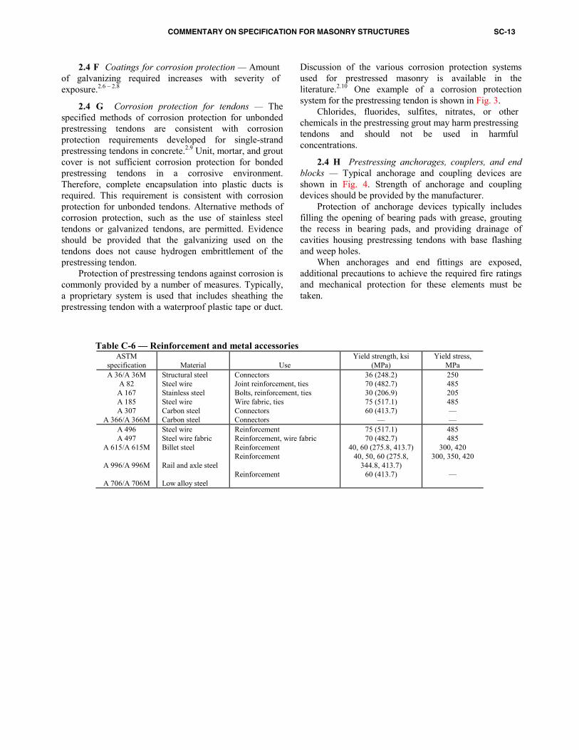
2.4 — Reinforcement, prestressing tendons, and metal accessories
See Table C-6 for a summary of properties.
2.4 B Prestressing tendons — The constructability aspects of prestressed masonry favor the use of rods or rigid strands with mechanical anchorage in ungrouted construction. Mild strength steel bars have been used in prestressed masonry installations in the United States.2.5 If mild strength bars (of less than 150 ksi [1034 MPa]) are used, determine the stress-relaxation characteristics by tests and document the results.
2.4 E Stainless steel — Corrosion resistance of stainless steel is greater than that of the other steels listed. Thus, it does not have to be coated for corrosion resistance.
COMMENTARY ON SPECIFICATION FOR MASONRY STRUCTURES SC-13
Table C-6 — Reinforcement and metal accessories
ASTM specification
Material
Use
Yield strength, ksi (MPa)
Yield stress, MPa
A 36/A 36M A 82
A 167 A 185 A 307
A 366/A 366M
Structural steel Steel wire Stainless steel Steel wire Carbon steel Carbon steel
Connectors Joint reinforcement, ties Bolts, reinforcement, ties Wire fabric, ties Connectors Connectors
36 (248.2) 70 (482.7) 30 (206.9) 75 (517.1) 60 (413.7)
—
250 485 205 485 — —
A 496 A 497
A 615/A 615M
A 996/A 996M
A 706/A 706M
Steel wire Steel wire fabric Billet steel Rail and axle steel Low alloy steel
Reinforcement Reinforcement, wire fabric Reinforcement Reinforcement Reinforcement
75 (517.1) 70 (482.7)
40, 60 (275.8, 413.7) 40, 50, 60 (275.8,
344.8, 413.7) 60 (413.7)
485 485
300, 420 300, 350, 420
—
2.4 F Coatings for corrosion protection — Amount of galvanizing required increases with severity of exposure.2.6 – 2.8
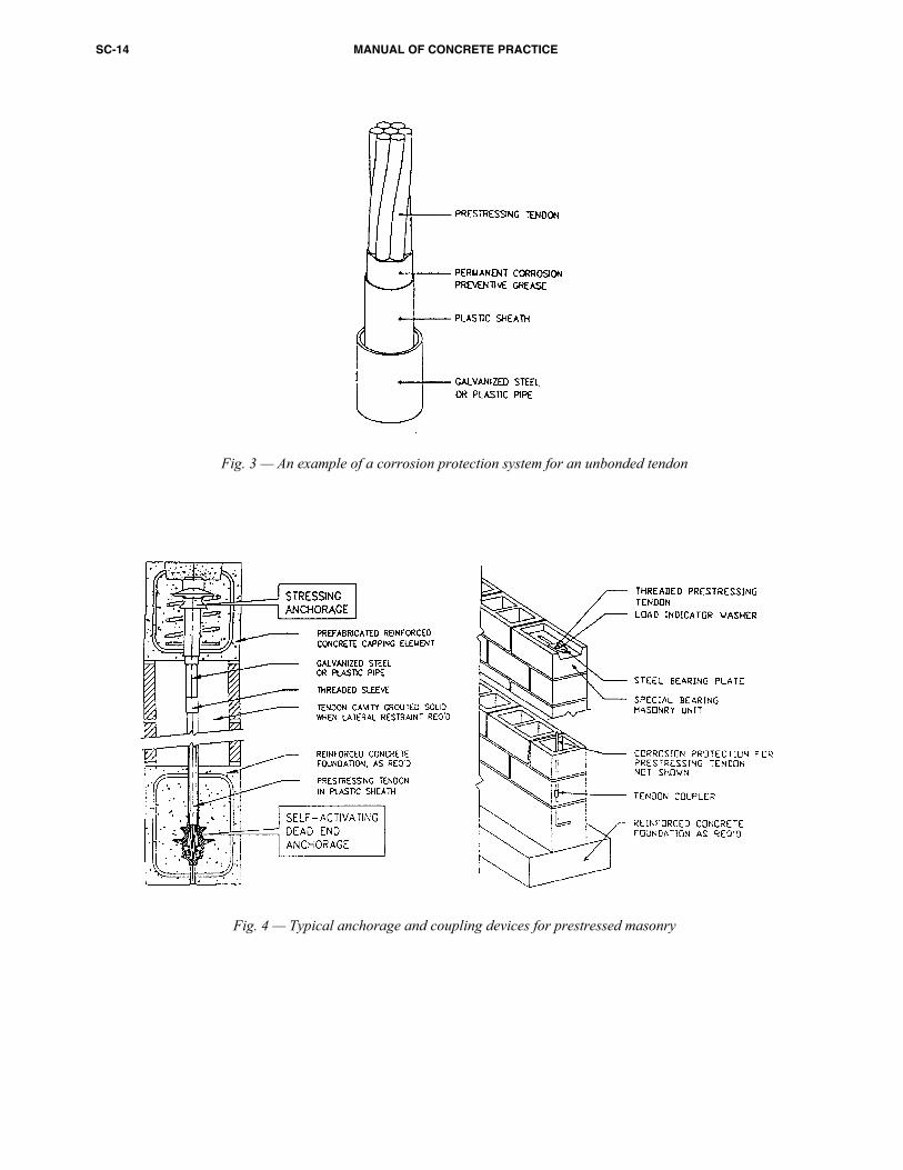
2.4 G Corrosion protection for tendons — The specified methods of corrosion protection for unbonded prestressing tendons are consistent with corrosion protection requirements developed for single-strand prestressing tendons in concrete.2.9 Unit, mortar, and grout cover is not sufficient corrosion protection for bonded prestressing tendons in a corrosive environment. Therefore, complete encapsulation into plastic ducts is required. This requirement is consistent with corrosion protection for unbonded tendons. Alternative methods of corrosion protection, such as the use of stainless steel tendons or galvanized tendons, are permitted. Evidence should be provided that the galvanizing used on the tendons does not cause hydrogen embrittlement of the prestressing tendon. Protection of prestressing tendons against corrosion is commonly provided by a number of measures. Typically, a proprietary system is used that includes sheathing the prestressing tendon with a waterproof plastic tape or duct.
Discussion of the various corrosion protection systems used for prestressed masonry is available in the literature.2.10 One example of a corrosion protection system for the prestressing tendon is shown in Fig. 3.
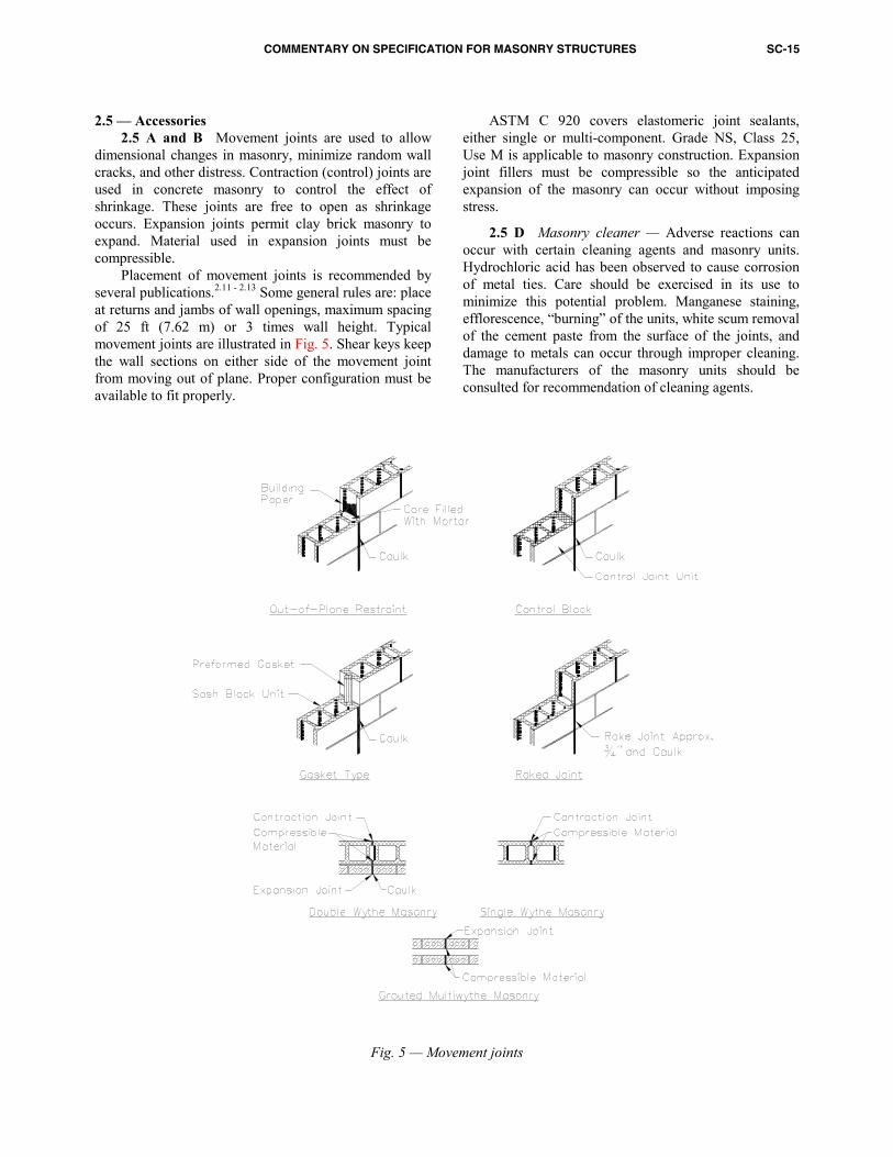
Chlorides, fluorides, sulfites, nitrates, or other chemicals in the prestressing grout may harm prestressing tendons and should not be used in harmful concentrations.2.4 H Prestressing anchorages, couplers, and end blocks — Typical anchorage and coupling devices are shown in Fig. 4. Strength of anchorage and coupling devices should be provided by the manufacturer.
Protection of anchorage devices typically includes filling the opening of bearing pads with grease, grouting the recess in bearing pads, and providing drainage of cavities housing prestressing tendons with base flashing and weep holes.
When anchorages and end fittings are exposed, additional precautions to achieve the required fire ratings and mechanical protection for these elements must be taken.
SC-14 MANUAL OF CONCRETE PRACTICE
Fig. 3 — An example of a corrosion protection system for an unbonded tendon
Fig. 4 — Typical anchorage and coupling devices for prestressed masonry
COMMENTARY ON SPECIFICATION FOR MASONRY STRUCTURES SC-15
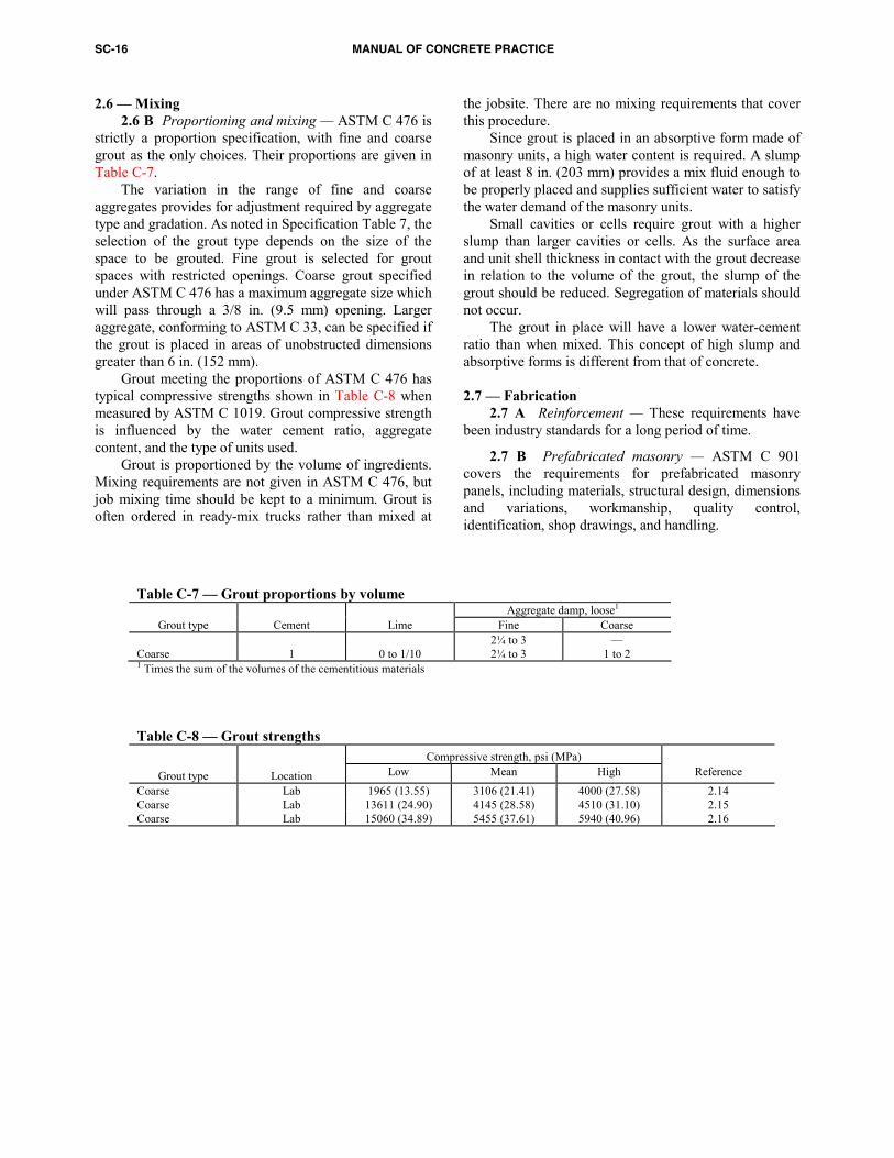
2.5 — Accessories 2.5 A and B Movement joints are used to allow dimensional changes in masonry, minimize random wall cracks, and other distress. Contraction (control) joints are used in concrete masonry to control the effect of shrinkage. These joints are free to open as shrinkage occurs. Expansion joints permit clay brick masonry to expand. Material used in expansion joints must be compressible. Placement of movement joints is recommended by several publications.2.11 - 2.13 Some general rules are: place at returns and jambs of wall openings, maximum spacing of 25 ft (7.62 m) or 3 times wall height. Typical movement joints are illustrated in Fig. 5. Shear keys keep the wall sections on either side of the movement joint from moving out of plane. Proper configuration must be available to fit properly.
Fig. 5 — Movement joints
ASTM C 920 covers elastomeric joint sealants, either single or multi-component. Grade NS, Class 25, Use M is applicable to masonry construction. Expansion joint fillers must be compressible so the anticipated expansion of the masonry can occur without imposing stress.
2.5 D Masonry cleaner — Adverse reactions can occur with certain cleaning agents and masonry units. Hydrochloric acid has been observed to cause corrosion of metal ties. Care should be exercised in its use to minimize this potential problem. Manganese staining, efflorescence, “burning” of the units, white scum removal of the cement paste from the surface of the joints, and damage to metals can occur through improper cleaning. The manufacturers of the masonry units should be consulted for recommendation of cleaning agents.
SC-16 MANUAL OF CONCRETE PRACTICE
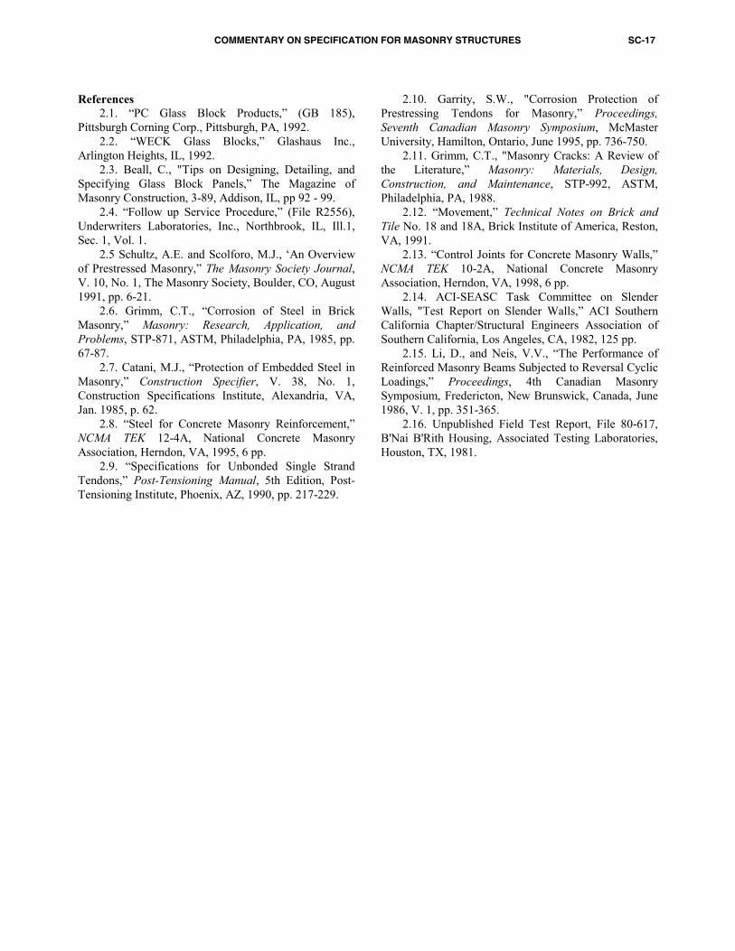
2.6 — Mixing 2.6 B Proportioning and mixing — ASTM C 476 is strictly a proportion specification, with fine and coarse grout as the only choices. Their proportions are given in Table C-7.
Table C-7 — Grout proportions by volumeAggregate damp, loose1 Grout type Cement Lime Fine Coarse
2¼ to 3 — Coarse 1 0 to 1/10 2¼ to 3 1 to 2 1 Times the sum of the volumes of the cementitious materials
The variation in the range of fine and coarse aggregates provides for adjustment required by aggregate type and gradation. As noted in Specification Table 7, the selection of the grout type depends on the size of the space to be grouted. Fine grout is selected for grout spaces with restricted openings. Coarse grout specified under ASTM C 476 has a maximum aggregate size which will pass through a 3/8 in. (9.5 mm) opening. Larger aggregate, conforming to ASTM C 33, can be specified if the grout is placed in areas of unobstructed dimensions greater than 6 in. (152 mm). Grout meeting the proportions of ASTM C 476 has typical compressive strengths shown in Table C-8 when measured by ASTM C 1019. Grout compressive strength is influenced by the water cement ratio, aggregate content, and the type of units used.
Table C-8 — Grout strengthsCompressive strength, psi (MPa) Grout type Location Low Mean High Reference
Coarse Lab 1965 (13.55) 3106 (21.41) 4000 (27.58) 2.14 Coarse Lab 13611 (24.90) 4145 (28.58) 4510 (31.10) 2.15 Coarse Lab 15060 (34.89) 5455 (37.61) 5940 (40.96) 2.16
Grout is proportioned by the volume of ingredients. Mixing requirements are not given in ASTM C 476, but job mixing time should be kept to a minimum. Grout is often ordered in ready-mix trucks rather than mixed at
the jobsite. There are no mixing requirements that cover this procedure. Since grout is placed in an absorptive form made of masonry units, a high water content is required. A slump of at least 8 in. (203 mm) provides a mix fluid enough to be properly placed and supplies sufficient water to satisfy the water demand of the masonry units. Small cavities or cells require grout with a higher slump than larger cavities or cells. As the surface area and unit shell thickness in contact with the grout decrease in relation to the volume of the grout, the slump of the grout should be reduced. Segregation of materials should not occur. The grout in place will have a lower water-cement ratio than when mixed. This concept of high slump and absorptive forms is different from that of concrete. 2.7 — Fabrication 2.7 A Reinforcement — These requirements have been industry standards for a long period of time.
2.7 B Prefabricated masonry — ASTM C 901 covers the requirements for prefabricated masonry panels, including materials, structural design, dimensions and variations, workmanship, quality control, identification, shop drawings, and handling.
COMMENTARY ON SPECIFICATION FOR MASONRY STRUCTURES SC-17
Houston, TX, 1981.
References 2.1. “PC Glass Block Products,” (GB 185), Pittsburgh Corning Corp., Pittsburgh, PA, 1992. 2.2. “WECK Glass Blocks,” Glashaus Inc., Arlington Heights, IL, 1992. 2.3. Beall, C., "Tips on Designing, Detailing, and Specifying Glass Block Panels,” The Magazine of Masonry Construction, 3-89, Addison, IL, pp 92 - 99. 2.4. “Follow up Service Procedure,” (File R2556), Underwriters Laboratories, Inc., Northbrook, IL, Ill.1, Sec. 1, Vol. 1.
2.5 Schultz, A.E. and Scolforo, M.J., ‘An Overview of Prestressed Masonry,” The Masonry Society Journal, V. 10, No. 1, The Masonry Society, Boulder, CO, August 1991, pp. 6-21. 2.6. Grimm, C.T., “Corrosion of Steel in Brick Masonry,” Masonry: Research, Application, and Problems, STP-871, ASTM, Philadelphia, PA, 1985, pp. 67-87. 2.7. Catani, M.J., “Protection of Embedded Steel in Masonry,” Construction Specifier, V. 38, No. 1, Construction Specifications Institute, Alexandria, VA, Jan. 1985, p. 62. 2.8. “Steel for Concrete Masonry Reinforcement,” NCMA TEK 12-4A, National Concrete Masonry Association, Herndon, VA, 1995, 6 pp.
2.9. “Specifications for Unbonded Single Strand Tendons,” Post-Tensioning Manual, 5th Edition, Post-Tensioning Institute, Phoenix, AZ, 1990, pp. 217-229.
2.10. Garrity, S.W., "Corrosion Protection of Prestressing Tendons for Masonry,” Proceedings, Seventh Canadian Masonry Symposium, McMaster University, Hamilton, Ontario, June 1995, pp. 736-750. 2.11. Grimm, C.T., "Masonry Cracks: A Review of the Literature,” Masonry: Materials, Design, Construction, and Maintenance, STP-992, ASTM, Philadelphia, PA, 1988. 2.12. “Movement,” Technical Notes on Brick and Tile No. 18 and 18A, Brick Institute of America, Reston, VA, 1991. 2.13. “Control Joints for Concrete Masonry Walls,” NCMA TEK 10-2A, National Concrete Masonry Association, Herndon, VA, 1998, 6 pp. 2.14. ACI-SEASC Task Committee on Slender Walls, "Test Report on Slender Walls,” ACI Southern California Chapter/Structural Engineers Association of Southern California, Los Angeles, CA, 1982, 125 pp. 2.15. Li, D., and Neis, V.V., “The Performance of Reinforced Masonry Beams Subjected to Reversal Cyclic Loadings,” Proceedings, 4th Canadian Masonry Symposium, Fredericton, New Brunswick, Canada, June 1986, V. 1, pp. 351-365. 2.16. Unpublished Field Test Report, File 80-617, B'Nai B'Rith Housing, Associated Testing Laboratories,
SC-18 MANUAL OF CONCRETE PRACTICE
PART 3 — EXECUTION
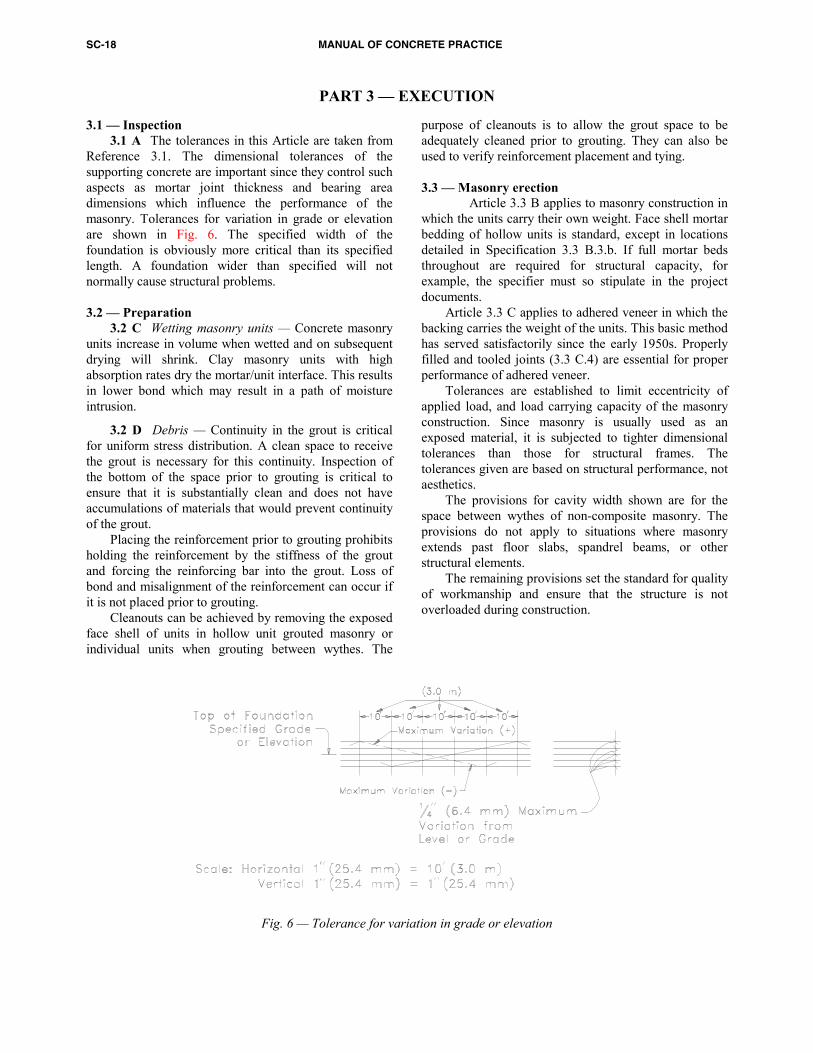
3.1 — Inspection 3.1 A The tolerances in this Article are taken from Reference 3.1. The dimensional tolerances of the supporting concrete are important since they control such aspects as mortar joint thickness and bearing area dimensions which influence the performance of the masonry. Tolerances for variation in grade or elevation are shown in Fig. 6. The specified width of the foundation is obviously more critical than its specified length. A foundation wider than specified will not normally cause structural problems.
Fig. 6 — Tolerance for variation in grade or elevation3.2 — Preparation 3.2 C Wetting masonry units — Concrete masonry units increase in volume when wetted and on subsequent drying will shrink. Clay masonry units with high absorption rates dry the mortar/unit interface. This results in lower bond which may result in a path of moisture intrusion.
3.2 D Debris — Continuity in the grout is critical for uniform stress distribution. A clean space to receive the grout is necessary for this continuity. Inspection of the bottom of the space prior to grouting is critical to ensure that it is substantially clean and does not have accumulations of materials that would prevent continuity of the grout. Placing the reinforcement prior to grouting prohibits holding the reinforcement by the stiffness of the grout and forcing the reinforcing bar into the grout. Loss of bond and misalignment of the reinforcement can occur if it is not placed prior to grouting. Cleanouts can be achieved by removing the exposed face shell of units in hollow unit grouted masonry or individual units when grouting between wythes. The
purpose of cleanouts is to allow the grout space to be adequately cleaned prior to grouting. They can also be used to verify reinforcement placement and tying. 3.3 — Masonry erection
Article 3.3 B applies to masonry construction in which the units carry their own weight. Face shell mortar bedding of hollow units is standard, except in locations detailed in Specification 3.3 B.3.b. If full mortar beds throughout are required for structural capacity, for example, the specifier must so stipulate in the project documents. Article 3.3 C applies to adhered veneer in which the backing carries the weight of the units. This basic method has served satisfactorily since the early 1950s. Properly filled and tooled joints (3.3 C.4) are essential for proper performance of adhered veneer. Tolerances are established to limit eccentricity of applied load, and load carrying capacity of the masonry construction. Since masonry is usually used as an exposed material, it is subjected to tighter dimensional tolerances than those for structural frames. The tolerances given are based on structural performance, not aesthetics. The provisions for cavity width shown are for the space between wythes of non-composite masonry. The provisions do not apply to situations where masonry extends past floor slabs, spandrel beams, or other structural elements. The remaining provisions set the standard for quality of workmanship and ensure that the structure is not overloaded during construction.
COMMENTARY ON SPECIFICATION FOR MASONRY STRUCTURES SC-19
3.4 — Reinforcement, tie, and anchor installation The requirements given ensure that: a. galvanic action is inhibited, b. location is as assumed in the design, c. there is sufficient clearance for grout and mortar to
surround reinforcement, ties, and anchors so stresses are properly transferred,
d. corrosion is delayed, and e. compatible lateral deflection of wythes is achieved.
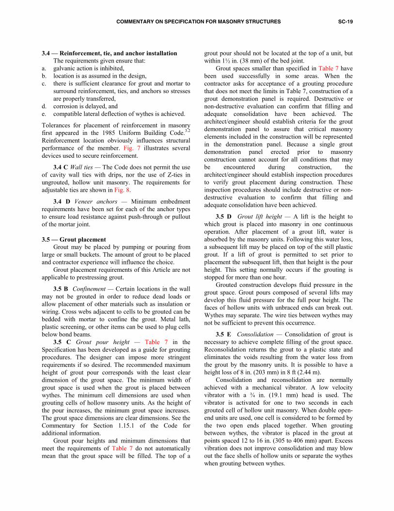
Tolerances for placement of reinforcement in masonry first appeared in the 1985 Uniform Building Code.3.2 Reinforcement location obviously influences structural performance of the member. Fig. 7 illustrates several devices used to secure reinforcement.
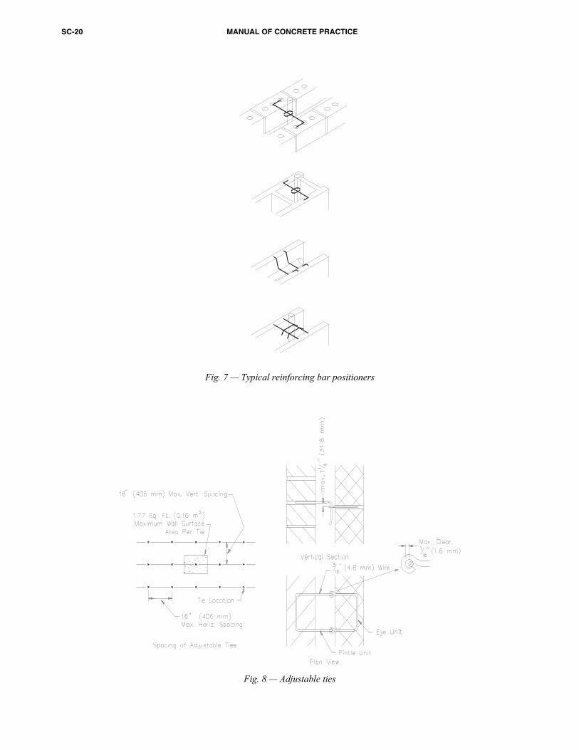
3.4 C Wall ties — The Code does not permit the use of cavity wall ties with drips, nor the use of Z-ties in ungrouted, hollow unit masonry. The requirements for adjustable ties are shown in Fig. 8.
3.4 D Veneer anchors — Minimum embedment requirements have been set for each of the anchor types to ensure load resistance against push-through or pullout of the mortar joint. 3.5 — Grout placement Grout may be placed by pumping or pouring from large or small buckets. The amount of grout to be placed and contractor experience will influence the choice.
Grout placement requirements of this Article are not applicable to prestressing grout.
3.5 B Confinement — Certain locations in the wall may not be grouted in order to reduce dead loads or allow placement of other materials such as insulation or wiring. Cross webs adjacent to cells to be grouted can be bedded with mortar to confine the grout. Metal lath, plastic screening, or other items can be used to plug cells below bond beams. 3.5 C Grout pour height — Table 7 in the Specification has been developed as a guide for grouting procedures. The designer can impose more stringent requirements if so desired. The recommended maximum height of grout pour corresponds with the least clear dimension of the grout space. The minimum width of grout space is used when the grout is placed between wythes. The minimum cell dimensions are used when grouting cells of hollow masonry units. As the height of the pour increases, the minimum grout space increases. The grout space dimensions are clear dimensions. See the Commentary for Section 1.15.1 of the Code for additional information. Grout pour heights and minimum dimensions that meet the requirements of Table 7 do not automatically mean that the grout space will be filled. The top of a
grout pour should not be located at the top of a unit, but within 1½ in. (38 mm) of the bed joint.
Grout spaces smaller than specified in Table 7 have been used successfully in some areas. When the contractor asks for acceptance of a grouting procedure that does not meet the limits in Table 7, construction of a grout demonstration panel is required. Destructive or non-destructive evaluation can confirm that filling and adequate consolidation have been achieved. The architect/engineer should establish criteria for the grout demonstration panel to assure that critical masonry elements included in the construction will be represented in the demonstration panel. Because a single grout demonstration panel erected prior to masonry construction cannot account for all conditions that may be encountered during construction, the architect/engineer should establish inspection procedures to verify grout placement during construction. These inspection procedures should include destructive or non-destructive evaluation to confirm that filling and adequate consolidation have been achieved.
3.5 D Grout lift height — A lift is the height to which grout is placed into masonry in one continuous operation. After placement of a grout lift, water is absorbed by the masonry units. Following this water loss, a subsequent lift may be placed on top of the still plastic grout. If a lift of grout is permitted to set prior to placement the subsequent lift, then that height is the pour height. This setting normally occurs if the grouting is stopped for more than one hour. Grouted construction develops fluid pressure in the grout space. Grout pours composed of several lifts may develop this fluid pressure for the full pour height. The faces of hollow units with unbraced ends can break out. Wythes may separate. The wire ties between wythes may not be sufficient to prevent this occurrence.
3.5 E Consolidation — Consolidation of grout is necessary to achieve complete filling of the grout space. Reconsolidation returns the grout to a plastic state and eliminates the voids resulting from the water loss from the grout by the masonry units. It is possible to have a height loss of 8 in. (203 mm) in 8 ft (2.44 m). Consolidation and reconsolidation are normally achieved with a mechanical vibrator. A low velocity vibrator with a ¾ in. (19.1 mm) head is used. The vibrator is activated for one to two seconds in each grouted cell of hollow unit masonry. When double open-end units are used, one cell is considered to be formed by the two open ends placed together. When grouting between wythes, the vibrator is placed in the grout at points spaced 12 to 16 in. (305 to 406 mm) apart. Excess vibration does not improve consolidation and may blow out the face shells of hollow units or separate the wythes when grouting between wythes.
SC-20 MANUAL OF CONCRETE PRACTICE
F
ig. 7 — Typical reinforcing bar positioners
Fig. 8 — Adjustable ties
COMMENTARY ON SPECIFICATION FOR MASONRY STRUCTURES SC-21
3.6 — Prestressing tendon installation and stressing
procedure Installation of tendons with the specified tolerances
is common practice. The methods of application and measurement of prestressing force are common techniques for prestressed concrete and masonry members. Designer and contractor should be experienced with prestressing and should consult the Post-Tensioning Institute’s Field Procedures Manual for Unbonded Single Strand Tendons3.3 or similar literature before conducting the Work. Critical aspects of the prestressing operation that require inspection include handling and storage of the prestressing tendons and anchorages, installation of the anchorage hardware into the foundation and capping members, integrity and continuity of the corrosion protection system for the prestressing tendons and anchorages, and the prestressing tendon stressing and grouting procedures.
The design method in Code Chapter 4 is based on an accurate assessment of the level of prestress. Tendon elongation and tendon force measurements with a calibrated gauge or load cell or by use of a calibrated dynamometer have proven to provide the required accuracy. For tendons using steels of less than 150 ksi (1034 MPa) strength, Direct Tension Indicator (DTI) washers also provide adequate accuracy. These washers have dimples which are intended to compress once a predetermined force is applied on them by the prestressing force. These washers were first developed by the steel industry for use with high-strength bolts and have been modified for use with prestressed masonry. The designer should verify the actual accuracy of DTI washers and document it in the design.
Burning and welding operations in the vicinity of prestressing tendons must be carefully performed since the heat may lower the tendon strength and cause failure of the stressed tendon. 3.7 — Field quality control
3.7 A The frequency of testing given has long been an industry standard.
3.7 B ASTM C 1019 requires a mold for the grout specimens made from the masonry units which will be in contact with the grout. Thus, the water absorption from the grout by the masonry units is simulated. Sampling and testing frequency may be based on the volume of grout to be placed rather than wall area. References 3.1. ACI Committee 117, "Standard Specifications for Tolerances for Concrete Construction and Materials (ACI 117-90)," American Concrete Institute, Detroit, MI, 1981, 10 pp. 3.2. Uniform Building Code, International Conference of Building Officials, Whittier, CA, 1985.
3.3. Field Procedures Manual for Unbonded Single Strand Tendons, 2nd Edition, Post-Tensioning Institute, Phoenix, AZ, 1994, 62 pp.