Embed Size (px)
Citation preview
Page 2 · LaserPak User’s Manual
TableofContentsIntroduction ............................................................................................... 3 Safety Terms and Symbols ....................................................................... 5 Quick Start ................................................................................................ 7 Installation ................................................................................................. 8 Control Modes ......................................................................................... 10 Settings ................................................................................................... 12 Cable Wiring for Modulation ................................................................... 14 Using the Cable R Setting ....................................................................... 14 Remote Mode Operation ......................................................................... 16 Installing the USB Drivers ....................................................................... 16 Interface Connectors ............................................................................... 16 Connecting to the LaserPak .................................................................... 19 Working With Thermistors ....................................................................... 20 Using the Analog Interface ...................................................................... 21 Grounding Considerations ...................................................................... 24 Photodiode Input Considerations ........................................................... 24 Using Limits ............................................................................................. 25 Thermal Considerations .......................................................................... 26 Specifications .......................................................................................... 27 Error Messages ....................................................................................... 28 Mechanical Drawings .............................................................................. 29 Changing the AC Line Voltage Setting ................................................... 31 Maintenance and Service ........................................................................ 34
LaserPak User’s Manual · Page 3
Introduction
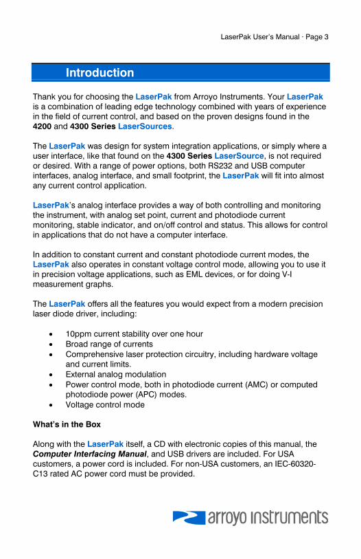
Thank you for choosing the LaserPak from Arroyo Instruments. Your LaserPak is a combination of leading edge technology combined with years of experience in the field of current control, and based on the proven designs found in the 4200 and 4300 Series LaserSources. The LaserPak was design for system integration applications, or simply where a user interface, like that found on the 4300 Series LaserSource, is not required or desired. With a range of power options, both RS232 and USB computer interfaces, analog interface, and small footprint, the LaserPak will fit into almost any current control application. LaserPak’s analog interface provides a way of both controlling and monitoring the instrument, with analog set point, current and photodiode current monitoring, stable indicator, and on/off control and status. This allows for control in applications that do not have a computer interface. In addition to constant current and constant photodiode current modes, the LaserPak also operates in constant voltage control mode, allowing you to use it in precision voltage applications, such as EML devices, or for doing V-I measurement graphs. The LaserPak offers all the features you would expect from a modern precision laser diode driver, including:
10ppm current stability over one hour Broad range of currents Comprehensive laser protection circuitry, including hardware voltage
and current limits. External analog modulation Power control mode, both in photodiode current (AMC) or computed
photodiode power (APC) modes. Voltage control mode
What’s in the Box Along with the LaserPak itself, a CD with electronic copies of this manual, the Computer Interfacing Manual, and USB drivers are included. For USA customers, a power cord is included. For non-USA customers, an IEC-60320-C13 rated AC power cord must be provided.
Page 4 · LaserPak User’s Manual
Accessories Arroyo Instruments also sells several accessories designed to work with the LaserPak. These include:
LaserSource Cable, 2m (p/n 1220B) This cable has DB-9 male/female connectors for interfacing to the LaserMount or other connectorized fixtures.
LaserSource Cable, 2m, Pigtailed (p/n 1221B) This cable has a female DB-9 connector for plugging into the LaserSource and tinned leads for wiring into custom solutions.
Pak Series Rack Mount Kit, 3 or 5 units (p/n 1402-RM) For installing your TECPak or LaserPak into a standard 19” rack. The kit accepts either 3 units for a 2U installation, or 5 units for a 3U installation.
RS-232 NULL Cable, 3m (p/n 1200-NULL) USB Cable, 3m (p/n 1201)
LaserPak User’s Manual · Page 5
Safety Terms and Symbols
The following safety-related terms are used in this manual:
Warnings (noted by the WARNING heading) explain dangers that could result in physical injury or death;
Cautions (noted by the CAUTION heading) explain conditions that could result in damage to the instrument, other equipment, or your device.
Notes (noted by the NOTES heading) are not safety-related, and are intended simply to point out important information.
If, at any time, any of the following conditions exist, or are suspected of existing, discontinue use of the unit until it can be inspected by qualified service personnel:
Visible damage to the unit, including damage or stress caused during product shipment;
Storage of the unit outside the standard storage temperature or humidity rating, or prolonged storage under harsh conditions;
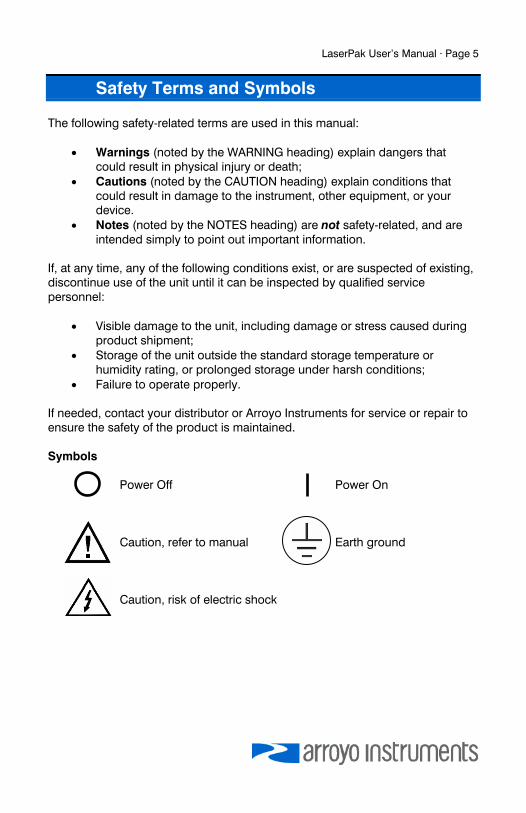
Failure to operate properly. If needed, contact your distributor or Arroyo Instruments for service or repair to ensure the safety of the product is maintained. Symbols Power Off Power On Caution, refer to manual Earth ground Caution, risk of electric shock
Page 6 · LaserPak User’s Manual
General Warnings
CAUTION There are no user-serviceable parts inside. All service and repair work shall be done by Arroyo Instruments or personnel authorized by Arroyo Instruments. Modifications done by non-authorized personnel will void the warranty. Please see the Service section later in this manual for instructions on how to obtain service for this instrument.
WARNING
To avoid electrical shock, ensure a 3-prong power cord is used, and is plugged into a earth-grounded receptacle. Failure to do so can result in severe injury or death.
WARNING
Potentially lethal voltages exist within this instrument. This instrument is intended for use by qualified personnel who understand the shock and laser hazards and are familiar with safety procedures required to avoid injury. Read this manual completely before attempting to use this product.
LaserPak User’s Manual · Page 7
Quick Start
The latest generation of the LaserPak requires the requires proper AC voltage selection before plugging into the AC mains. After unpacking the unit, ensure that the voltage selection is set to the correct voltage. This is critical, as incorrect voltages can damage the unit. The LaserPak is factory configured to the destination county’s AC line voltage prior to shipment, and should not need to be changed. See Verifying the Voltage Selection in the Installation section below on how to identify the voltage settings of the instrument. Once the voltage selection has been completed, plug the AC cord into the unit and into the wall outlet. Turn on the power switch located on the IPC, and the unit will power up. The AC Power LED should light, and the On / Error LED should remain dark. Control of the LaserPak can be done two ways: use the RS232 or USB computer interfaces and control the instrument from the PC, or use the analog interface. This quick start guide uses the computer interface. More information on the analog interface can be found later in the manual. To control the LaserPak from the PC, use the Arroyo Control software located on the CD that came with the instrument (it can also be downloaded from our web site). The software is located in the Software folder on the CD. Simply launch the installer and follow the on-screen prompts. Once the software is installed, plug the instrument into your RS-232 or USB interface. For USB users, the instrument may also ask for drivers, which can either be automatically downloaded from the Windows Update site or manually installed from the CD. Launch Arroyo Control, and in the LaserSource panel (if one is not visible, click Add Panel in the lower right of the window, and click Add a Laser Panel), select the communications port to which your LaserPak is connected. For USB users, this will usually be the highest numbered port in the list. Click Connect, and Arroyo Control will begin controlling the LaserPak. Once connected, you will be able to adjust settings, limits, and turn the output on or off. Next, connect the cable between your LaserMount or other fixture and the Output connector of the LaserPak. We recommend using our cables as they have been designed to work well with the LaserPak. If using your own cables, ensure they have been properly wired according to the pin-out of the LaserPak and your fixture.
Page 8 · LaserPak User’s Manual
Prior to turning the output on, click the Settings… button and adjust the current and voltage limits as appropriate for your device. You will typically want the limits to be 10% or more above the operation limits of your device. When setting the voltage limit, take into account the voltage loss in the cable, which can amount to several tenths of a volt at higher currents. When first turning on the system, start with a set point of 0mA and turn the output on. Initially increase in small steps (a few milliamps) to ensure the wiring is correct. Once the system appears to be running correctly, you can adjust the set point to the desired operating value. It’s that simple. For more detailed operating and installation instructions, read on.
Installation
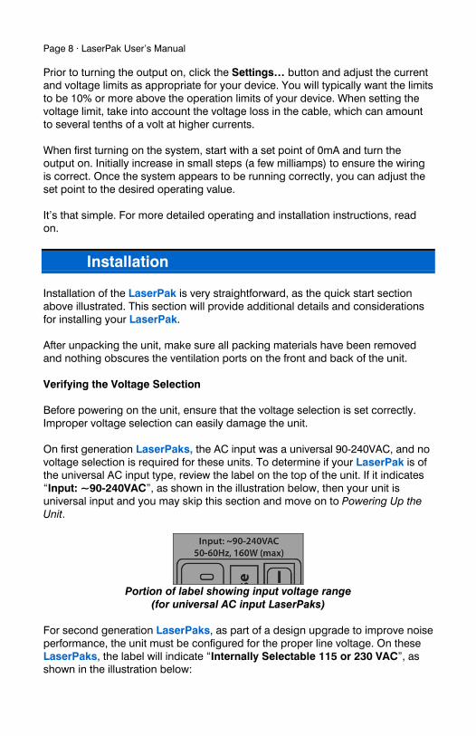
Installation of the LaserPak is very straightforward, as the quick start section above illustrated. This section will provide additional details and considerations for installing your LaserPak. After unpacking the unit, make sure all packing materials have been removed and nothing obscures the ventilation ports on the front and back of the unit. Verifying the Voltage Selection Before powering on the unit, ensure that the voltage selection is set correctly. Improper voltage selection can easily damage the unit. On first generation LaserPaks, the AC input was a universal 90-240VAC, and no voltage selection is required for these units. To determine if your LaserPak is of the universal AC input type, review the label on the top of the unit. If it indicates “Input: ~90-240VAC”, as shown in the illustration below, then your unit is universal input and you may skip this section and move on to Powering Up the Unit.
Portion of label showing input voltage range
(for universal AC input LaserPaks) For second generation LaserPaks, as part of a design upgrade to improve noise performance, the unit must be configured for the proper line voltage. On these LaserPaks, the label will indicate “Internally Selectable 115 or 230 VAC”, as shown in the illustration below:
LaserPak User’s Manual · Page 9
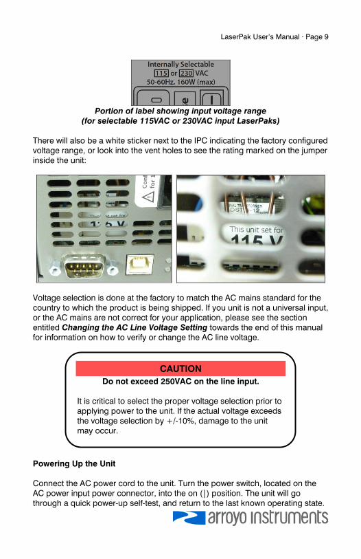
Portion of label showing input voltage range
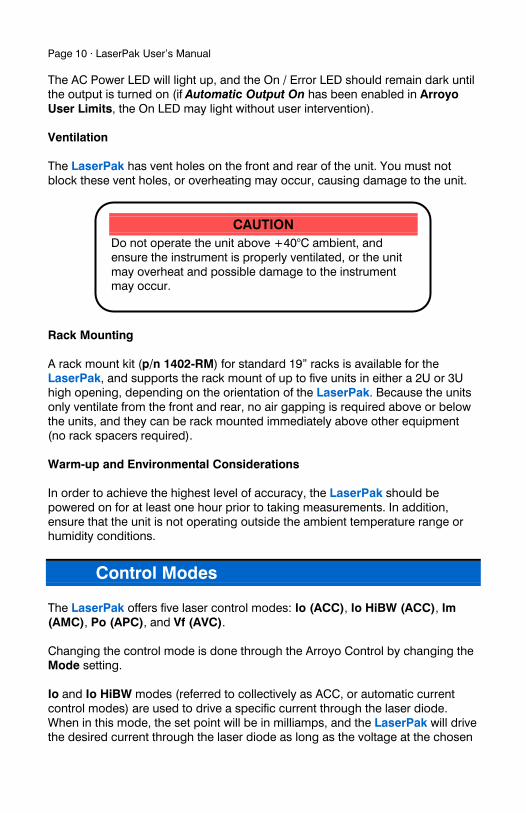
(for selectable 115VAC or 230VAC input LaserPaks) There will also be a white sticker next to the IPC indicating the factory configured voltage range, or look into the vent holes to see the rating marked on the jumper inside the unit:
Voltage selection is done at the factory to match the AC mains standard for the country to which the product is being shipped. If you unit is not a universal input, or the AC mains are not correct for your application, please see the section entitled Changing the AC Line Voltage Setting towards the end of this manual for information on how to verify or change the AC line voltage.
Powering Up the Unit Connect the AC power cord to the unit. Turn the power switch, located on the AC power input power connector, into the on (|) position. The unit will go through a quick power-up self-test, and return to the last known operating state.
CAUTION
Do not exceed 250VAC on the line input. It is critical to select the proper voltage selection prior to applying power to the unit. If the actual voltage exceeds the voltage selection by +/-10%, damage to the unit may occur.
Page 10 · LaserPak User’s Manual
The AC Power LED will light up, and the On / Error LED should remain dark until the output is turned on (if Automatic Output On has been enabled in Arroyo User Limits, the On LED may light without user intervention). Ventilation The LaserPak has vent holes on the front and rear of the unit. You must not block these vent holes, or overheating may occur, causing damage to the unit.
Rack Mounting A rack mount kit (p/n 1402-RM) for standard 19” racks is available for the LaserPak, and supports the rack mount of up to five units in either a 2U or 3U high opening, depending on the orientation of the LaserPak. Because the units only ventilate from the front and rear, no air gapping is required above or below the units, and they can be rack mounted immediately above other equipment (no rack spacers required). Warm-up and Environmental Considerations In order to achieve the highest level of accuracy, the LaserPak should be powered on for at least one hour prior to taking measurements. In addition, ensure that the unit is not operating outside the ambient temperature range or humidity conditions.
Control Modes
The LaserPak offers five laser control modes: Io (ACC), Io HiBW (ACC), Im (AMC), Po (APC), and Vf (AVC). Changing the control mode is done through the Arroyo Control by changing the Mode setting. Io and Io HiBW modes (referred to collectively as ACC, or automatic current control modes) are used to drive a specific current through the laser diode. When in this mode, the set point will be in milliamps, and the LaserPak will drive the desired current through the laser diode as long as the voltage at the chosen
CAUTION
Do not operate the unit above +40°C ambient, and ensure the instrument is properly ventilated, or the unit may overheat and possible damage to the instrument may occur.
LaserPak User’s Manual · Page 11
set point does not exceed the voltage limit. In Io mode, you will be limited to less than a 10 Hz bandwidth. To modulate above that rate, use the Io HiBW, which is a high bandwidth current mode supporting modulation. Im mode (also referred to as AMC, or automatic monitor photodiode control, mode) is used to control the laser diode using the monitor diode feedback. You select the target monitor diode current, and the LaserPak will drive exactly enough forward current through the laser diode to generate the selected monitor diode current. Only low frequency modulation (10Hz or less) is possible in Im mode due to the feedback latencies of the photodiode itself. Po mode (also referred to as APC, or automatic power control, mode) is simply Im mode with a mathematical constant applied to the set point, providing a convenient way of operating in milliwatts. Using the PD Resp factor (in μA/mW), a Po set point is internally converted to an equivalent Im set point by the driver, which is then used to control the photodiode feedback. For example, if the PD Resp factor was 10, then a set point of 1mW would be the same as a set point of 10μA. Vf mode (also referred to as AVC, or automatic voltage control, mode) is used to control the voltage driven through the device. Unlike ACC mode, AVC mode allows the current to drive to whatever current is necessary to achieve the voltage set point, so long as it does not exceed the current limit. As with Im mode, only low frequency modulation (10Hz or less) is possible in Vf mode. Modulation The instrument supports external analog modulation using the modulation pins on the analog interface connector. Modulation rates vary by model, so see your model’s specification for the maximum modulation rates. Only Io HiBW mode supports high speed modulation. All other modes of operation have a modulation bandwidth of 10Hz or less.
Page 12 · LaserPak User’s Manual
Settings
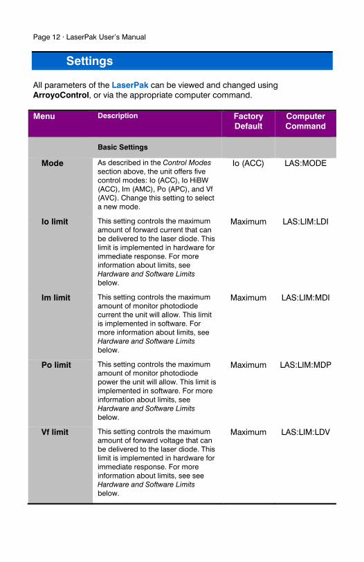
All parameters of the LaserPak can be viewed and changed using ArroyoControl, or via the appropriate computer command. Menu Description Factory
Default Computer Command
Basic Settings
Mode As described in the Control Modes section above, the unit offers five control modes: Io (ACC), Io HiBW (ACC), Im (AMC), Po (APC), and Vf (AVC). Change this setting to select a new mode.
Io (ACC) LAS:MODE
Io limit This setting controls the maximum amount of forward current that can be delivered to the laser diode. This limit is implemented in hardware for immediate response. For more information about limits, see Hardware and Software Limits below.
Maximum LAS:LIM:LDI
Im limit This setting controls the maximum amount of monitor photodiode current the unit will allow. This limit is implemented in software. For more information about limits, see Hardware and Software Limits below.
Maximum LAS:LIM:MDI
Po limit This setting controls the maximum amount of monitor photodiode power the unit will allow. This limit is implemented in software. For more information about limits, see Hardware and Software Limits below.
Maximum LAS:LIM:MDP
Vf limit This setting controls the maximum amount of forward voltage that can be delivered to the laser diode. This limit is implemented in hardware for immediate response. For more information about limits, see see Hardware and Software Limits below.
Maximum LAS:LIM:LDV
LaserPak User’s Manual · Page 13
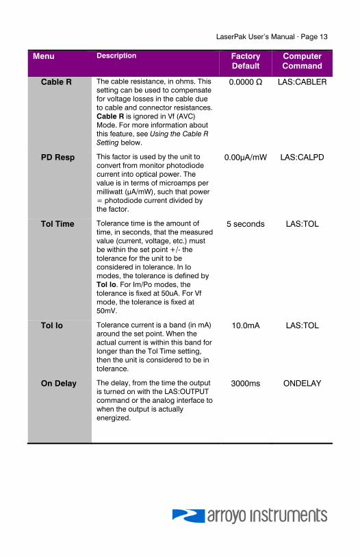
Menu Description Factory Default
Computer Command
Cable R The cable resistance, in ohms. This setting can be used to compensate for voltage losses in the cable due to cable and connector resistances. Cable R is ignored in Vf (AVC) Mode. For more information about this feature, see Using the Cable R Setting below.
0.0000 Ω LAS:CABLER
PD Resp This factor is used by the unit to convert from monitor photodiode current into optical power. The value is in terms of microamps per milliwatt (μA/mW), such that power = photodiode current divided by the factor.
0.00μA/mW LAS:CALPD
Tol Time Tolerance time is the amount of time, in seconds, that the measured value (current, voltage, etc.) must be within the set point +/- the tolerance for the unit to be considered in tolerance. In Io modes, the tolerance is defined by Tol Io. For Im/Po modes, the tolerance is fixed at 50uA. For Vf mode, the tolerance is fixed at 50mV.
5 seconds LAS:TOL
Tol Io Tolerance current is a band (in mA) around the set point. When the actual current is within this band for longer than the Tol Time setting, then the unit is considered to be in tolerance.
10.0mA LAS:TOL
On Delay The delay, from the time the output is turned on with the LAS:OUTPUT command or the analog interface to when the output is actually energized.
3000ms ONDELAY
Page 14 · LaserPak User’s Manual
Cable Wiring for Modulation
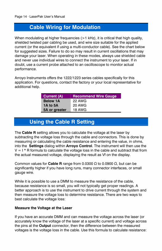
When modulating at higher frequencies (>1 kHz), it is critical that high quality, shielded twisted pair cabling be used, and wire size suitable for the applied current (or the equivalent if using a multi-conductor cable). See the chart below for suggested sizes. Failure to do so may result in current oscillations that may damage your laser. When operating in these modes, always use shielded cable and never use individual wires to connect the instrument to your laser. If in doubt, use a current probe attached to an oscilloscope to monitor actual performance. Arroyo Instruments offers the 1222/1223 series cables specifically for this application. For questions, contact the factory or your local representative for additional help.
Current (A) Recommend Wire Gauge Below 1A 22 AWG 1A to 5A 20 AWG 5A or greater 18 AWG
Using the Cable R Setting
The Cable R setting allows you to calculate the voltage at the laser by subtracting the voltage loss through the cable and connectors. This is done by measuring or calculating the cable resistance and entering the value, in ohms, into the Settings dialog within Arroyo Control. The instrument will then use the V = I * R formula to calculate the voltage loss in the cable and subtract that from the actual measured voltage, displaying the result as Vf on the display. Common values for Cable R range from 0.0300 Ω to 0.0900 Ω, but can be significantly higher if you have long runs, many connector interfaces, or small gauge wire. While it is possible to use a DMM to measure the resistance of the cable, because resistance is so small, you will not typically get proper readings. A better approach is to use the instrument to drive current through the system and then measure the voltage loss to determine resistance. There are two ways to best calculate the voltage loss: Measure the Voltage at the Laser If you have an accurate DMM and can measure the voltage across the laser (or accurately know the voltage of the laser at a specific current) and voltage across the pins at the Output connector, then the difference between the measured voltages is the voltage loss in the cable. Use this formula to calculate resistance:
LaserPak User’s Manual · Page 15
AMPS
laserOutput
I
VVRCable
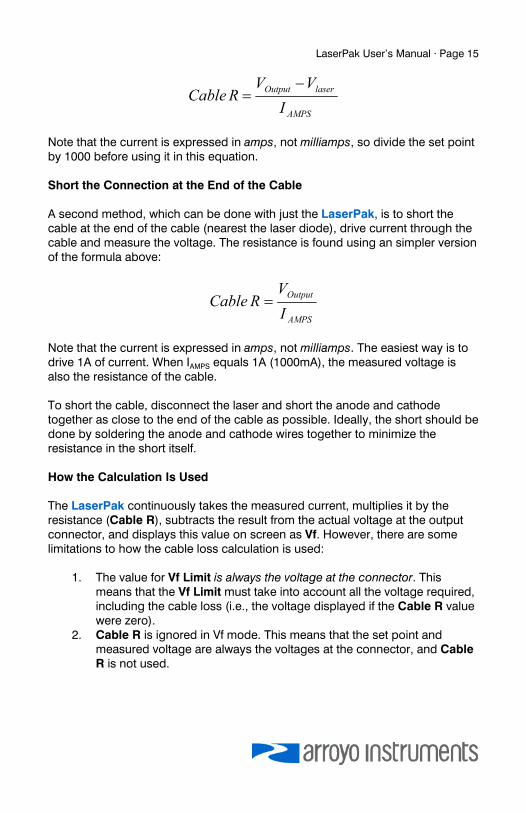
Note that the current is expressed in amps, not milliamps, so divide the set point by 1000 before using it in this equation. Short the Connection at the End of the Cable A second method, which can be done with just the LaserPak, is to short the cable at the end of the cable (nearest the laser diode), drive current through the cable and measure the voltage. The resistance is found using an simpler version of the formula above:
AMPS
Output
I
VRCable
Note that the current is expressed in amps, not milliamps. The easiest way is to drive 1A of current. When IAMPS equals 1A (1000mA), the measured voltage is also the resistance of the cable. To short the cable, disconnect the laser and short the anode and cathode together as close to the end of the cable as possible. Ideally, the short should be done by soldering the anode and cathode wires together to minimize the resistance in the short itself. How the Calculation Is Used The LaserPak continuously takes the measured current, multiplies it by the resistance (Cable R), subtracts the result from the actual voltage at the output connector, and displays this value on screen as Vf. However, there are some limitations to how the cable loss calculation is used:
1. The value for Vf Limit is always the voltage at the connector. This means that the Vf Limit must take into account all the voltage required, including the cable loss (i.e., the voltage displayed if the Cable R value were zero).
2. Cable R is ignored in Vf mode. This means that the set point and measured voltage are always the voltages at the connector, and Cable R is not used.
Page 16 · LaserPak User’s Manual
Remote Mode Operation
Remote mode operation is when the LaserPak is being controlled by a computer over the USB or RS232 interfaces. Details on how to communicate with the LaserPak can be found in the Computer Interfacing Manual which is included on the CD that accompanied this product.
Installing the USB Drivers
Using the LaserPak via USB is just as simple as using the serial port. In fact, once you have installed the USB drivers, the instrument will appear as a virtual serial port that you can use just like a normal serial port. To install the drivers, simply plug in the instrument to your computer. When the Add New Hardware wizard appears, insert the CD you received with the LaserPak and follow the on-screen instructions. Once the drivers are installed, the LaserPak will be available as a standard COM (serial) port. In the event you have multiple Arroyo Instruments products plugged in simultaneously, you will need to experiment to see which instrument was assigned to which port. For example, you could send a *IDN? query and see which instrument goes into remote mode.
Interface Connectors
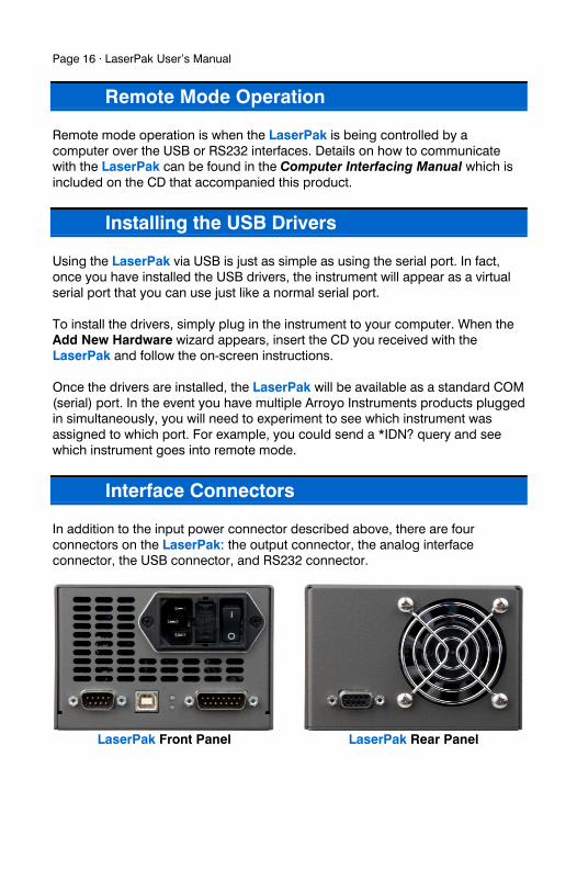
In addition to the input power connector described above, there are four connectors on the LaserPak: the output connector, the analog interface connector, the USB connector, and RS232 connector.
LaserPak Front Panel LaserPak Rear Panel
LaserPak User’s Manual · Page 17
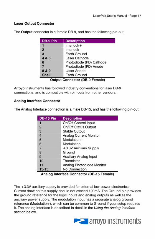
Laser Output Connector The Output connector is a female DB-9, and has the following pin-out:
DB-9 Pin Description 1 Interlock+ 2 Interlock – 3 Earth Ground 4 & 5 Laser Cathode 6 Photodiode (PD) Cathode 7 Photodiode (PD) Anode 8 & 9 Laser Anode Shell Earth Ground
Output Connector (DB-9 Female) Arroyo Instruments has followed industry conventions for laser DB-9 connections, and is compatible with pin-outs from other vendors. Analog Interface Connector The Analog Interface connection is a male DB-15, and has the following pin-out:
DB-15 Pin Description 1 On/Off Control Input 2 On/Off Status Output 3 Stable Output 4 Analog Current Monitor 5 Modulation+ 6 Modulation- 7 +3.3V Auxiliary Supply 8 Ground 9 Auxiliary Analog Input 10 Thermistor 11 Analog Photodiode Monitor 13-15 No Connection Analog Interface Connector (DB-15 Female)
The +3.3V auxiliary supply is provided for external low-power electronics. Current draw on this supply should not exceed 100mA. The Ground pin provides the ground reference for the logic inputs and analog outputs as well as the auxiliary power supply. The modulation input has a separate analog ground reference (Modulation-), which can be common to Ground if your setup requires it. The analog interface is described in detail in the Using the Analog Interface section below.
Page 18 · LaserPak User’s Manual
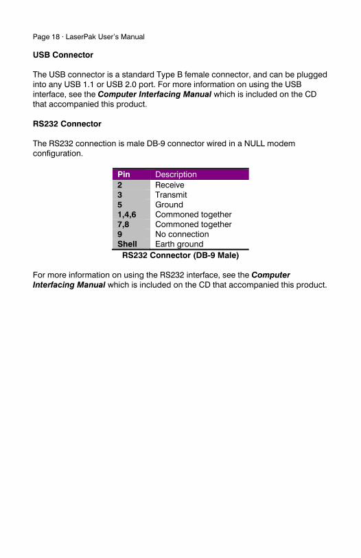
USB Connector The USB connector is a standard Type B female connector, and can be plugged into any USB 1.1 or USB 2.0 port. For more information on using the USB interface, see the Computer Interfacing Manual which is included on the CD that accompanied this product. RS232 Connector The RS232 connection is male DB-9 connector wired in a NULL modem configuration.
Pin Description 2 Receive 3 Transmit 5 Ground 1,4,6 Commoned together 7,8 Commoned together 9 No connection Shell Earth ground RS232 Connector (DB-9 Male)
For more information on using the RS232 interface, see the Computer Interfacing Manual which is included on the CD that accompanied this product.
LaserPak User’s Manual · Page 19
Connecting to the LaserPak
A laser diode is very sensitive to electro-static discharge (ESD), over-voltage, and over-current conditions. When connecting a laser to the LaserPak, make sure proper ESD procedures are taken. In addition, it is critical that the proper current limit and voltage limit be set for the laser diode. Exceeding the laser diode’s rated current or voltage can damage or destroy the laser diode, and the LaserPak’s hardware protection features can only protect the laser diode if these limits are properly set.
The Laser anode and cathode outputs are electrically isolated from earth ground, as are the photodiode inputs. However, the ground of the analog interface cannot be connected to either the laser anode or cathode. When connecting multiple LaserPaks using a common anode or cathode connection (such as a multi-stage laser), typically only one point of connection can be made between LaserPaks. Please contact the factory to verify your wiring plan.
See the manual for your laser (and fixture) for additional safety and operational information.
NOTE
Connections to the LaserPak and the laser diode fixture must be secure. Tighten any screws on the DB-9 connectors, and make sure all connections are in good condition. Poor or intermittent connections can damage or destroy the laser diode.
CAUTION
The interlock connections must be kept isolated from all other connections and from earth ground. Failure to do so may damage the instrument.
NOTE
While connecting to only one of the DB-9’s cathode (pins 4 and 5) and anode (pins 8 and 9) connections is required, you should connect cathode to both pins 4 and 5, and anode to both pins 8 and 9 to provide the best connection through the DB-9 connector.
Page 20 · LaserPak User’s Manual
Working With Thermistors
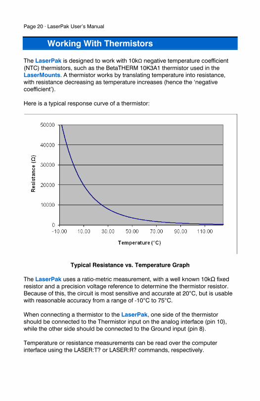
The LaserPak is designed to work with 10kΩ negative temperature coefficient (NTC) thermistors, such as the BetaTHERM 10K3A1 thermistor used in the LaserMounts. A thermistor works by translating temperature into resistance, with resistance decreasing as temperature increases (hence the ‘negative coefficient’). Here is a typical response curve of a thermistor:
Typical Resistance vs. Temperature Graph
The LaserPak uses a ratio-metric measurement, with a well known 10kΩ fixed resistor and a precision voltage reference to determine the thermistor resistor. Because of this, the circuit is most sensitive and accurate at 20°C, but is usable with reasonable accuracy from a range of -10°C to 75°C. When connecting a thermistor to the LaserPak, one side of the thermistor should be connected to the Thermistor input on the analog interface (pin 10), while the other side should be connected to the Ground input (pin 8). Temperature or resistance measurements can be read over the computer interface using the LASER:T? or LASER:R? commands, respectively.
LaserPak User’s Manual · Page 21
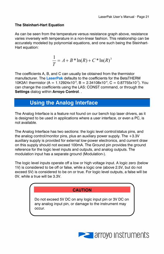
The Steinhart-Hart Equation As can be seen from the temperature versus resistance graph above, resistance varies inversely with temperature in a non-linear fashion. This relationship can be accurately modeled by polynomial equations, and one such being the Steinhart-Hart equation:
3)ln(*)ln(*1
RCRBAT
The coefficients A, B, and C can usually be obtained from the thermistor manufacturer. The LaserPak defaults to the coefficients for the BetaTHERM 10K3A1 thermistor (A = 1.12924x10⁻³, B = 2.34108x10⁻⁴, C = 0.87755x10⁻⁷). You can change the coefficients using the LAS: CONST command, or through the Settings dialog within Arroyo Control. .
Using the Analog Interface
The Analog Interface is a feature not found on our bench top laser drivers, as it is designed to be used in applications where a user interface, or even a PC, is not available. The Analog Interface has two sections: the logic level control/status pins, and the analog control/monitor pins, plus an auxiliary power supply. The +3.3V auxiliary supply is provided for external low-power electronics, and current draw on this supply should not exceed 100mA. The Ground pin provides the ground reference for the logic level inputs and outputs, and analog outputs. The modulation input has a separate ground (Modulation-). The logic level inputs operate off a low or high voltage input. A logic zero (below 1V) is considered to be off or false, while a logic one (above 2.5V, but do not exceed 5V) is considered to be on or true. For logic level outputs, a false will be 0V, while a true will be 3.3V.
CAUTION
Do not exceed 5V DC on any logic input pin or 3V DC on any analog input pin, or damage to the instrument may occur.
Page 22 · LaserPak User’s Manual
There are three logic level pins:
On/Off Control Input This input controls the on/off state of the instrument. When this input transitions from off to on, the output is turned on and begins controlling to the set point. Similarly, when it transitions from on to off, the output is turned off. It is possible to use the analog interface with the computer interface, as the LaserPak is looking for a change in the logic input to turn the output on or off, as appropriate (considered an edge triggered input, rather than a level triggered input). It is possible for the computer interface to turn the output on or off as well, ignoring the steady state of the logic input. However, as soon as the logic input changes state, then the LaserPak’s output will also be changed to reflect the new state. For example, if the logic input goes from false to true (turn the output on), then the output will be turned on. Later, if a LAS:OUT OFF is received from the computer (turn the output off), then the output will be turned off, even though the logic input is still high. Likewise, if the computer sends a LAS:OUT ON, the output will be turned on, regardless of the logic input’s state. Later, if the logic input goes from true to false, then the output will be turned off. In this way, on/off operation can be supported simultaneously through the analog interface and the PC interface without conflict. On/Off Status Output This logic level output reflects the present output state of the instrument. When it is on, this output will be high. Stable Status Output The output is considered stable when the actual drive value has remained within the tolerance band around the set point for a specific amount of time (as defined by the tolerance settings). Once the output is considered stable, then this logic level output will be set to high. If the set point is changed, or a disturbance causes the actual output to fall outside the tolerance setting, then this logic level output will be set to false, and the process starts over. The output will also be false whenever the output is off.
In addition, there are several analog signals:
Analog Modulation Input The analog modulation input allows the user to change the set point using a voltage signal. The voltage input range is from 0V to 10V, where
LaserPak User’s Manual · Page 23
0V equals a set point of zero, and 10V equals a set point of the full scale range. For example, on a 5A driver, 10V input would attempt to drive 5A, which is the full scale of the instrument. In this case, the transfer function would be 500mA/V. The modulation input is added to the set point of the instrument. For example, if you were operating in Io Mode, and the set point was 500mA on a 5A driver, and you applied a voltage of 4V (which is equal to 2A), then the output drive current would be 2.5A.
Analog Current Monitor Output The actual current being driven by the instrument is provided as an output voltage, where 2.5V equals full scale of the output. Analog Photodiode Current Monitor Output The actual photodiode current measured by the instrument is provided as an output voltage, where 2.5V equals FS of the output. Thermistor Input Thermistor operation is described in the Working With Thermistors section above. The thermistor should be connected to the Thermistor and Ground pins. Auxiliary Analog Input This input accepts from 0V to 2.5V input, and it’s measurement can be read using the LAS:AUX? query.
Connecting to the Analog Interface Connecting to the Analog Interface is very straightforward. Because the inputs and outputs are buffered, you do not need any external filters or buffers, unless your application requires it. The logic level interfaces are all high impedance, as is the modulation input. The analog current and photodiode current monitors output are driven through a 499Ω resistor to protect against output shorting.
CAUTION The allowable voltage input range on the analog input is 0 to 10V. Be sure not to exceed 10V on the input, or damage to the instrument may occur.
Page 24 · LaserPak User’s Manual
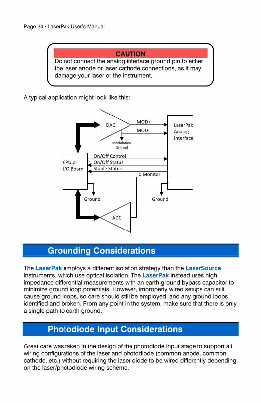
A typical application might look like this:
Grounding Considerations
The LaserPak employs a different isolation strategy than the LaserSource instruments, which use optical isolation. The LaserPak instead uses high impedance differential measurements with an earth ground bypass capacitor to minimize ground loop potentials. However, improperly wired setups can still cause ground loops, so care should still be employed, and any ground loops identified and broken. From any point in the system, make sure that there is only a single path to earth ground.
Photodiode Input Considerations
Great care was taken in the design of the photodiode input stage to support all wiring configurations of the laser and photodiode (common anode, common cathode, etc.) without requiring the laser diode to be wired differently depending on the laser/photodiode wiring scheme.
CAUTION Do not connect the analog interface ground pin to either the laser anode or laser cathode connections, as it may damage your laser or the instrument.
Modulation Ground
MOD‐
On/Off ControlOn/Off StatusStable Status
DAC
ADC
CPU or I/O Board
LaserPakAnalog Interface
MOD+
Io Monitor
GroundGround
LaserPak User’s Manual · Page 25
The LaserPak comes configured for -3V photodiode bias, which is typically sufficient for any application, although no bias and -5V bias are also available. The -5V bias cannot be used if either side of the laser is connected to the photodiode cathode. The “no bias” setting is not typically used, as the current of the photodiode will slightly forward bias the photodiode, which is more than offset by -3V or -5V bias, and is the primary reason for the reverse bias. To change the bias setting, the cover must be removed and a jumper changed on the circuit board. Make sure the power cord is unplugged from the unit, and also remove the output cable if it is connected. Both jack screws on the output connector need to be removed, as do all 6 black flat head screws on either side of the enclosure. Slide the top off the OUTPUT connector and rotate up. The fan is mounted to the portion of the enclosure you are lifting off, so take care that the power connector to the fan is not stressed. To change the bias setting, locate J11 on the circuit board. It is on the fan end of the board, right next to the large white power connector. On the board you will see three settings: “NO”, “3V”, and “5V”. Move the jumper to the setting you desire. When replacing the cover, if the fan was unplugged, make sure to plug it back in (the fan connector is J3, also marked “FAN” on the circuit board). Take care not to pinch the fan wires as the top is put back into place. Screw the six flat head screws back in, and gently screw in the jack screws (do NOT over-tighten the jack screws or you run the risk of snapping them off in the connector).
Using Limits
The LaserPak provides several limit features for protection of the laser diode. These include current, voltage, photodiode current, and photodiode power limits. Both the current and voltage limits are implemented in hardware, providing for fast response to changes in laser diode operation. When a voltage limit is detected, the output is immediately shutdown. Because of the sensitivity of the voltage limit, operating near the limit (within one to two hundred millivolts) is not recommended. In general, you should set the voltage limit to 0.1V to 0.2V higher than any anticipated operating point. The voltage limit is tested against the voltage at the connector. Any Cable R value is ignored, as Cable R is a software only calculation, and the voltage limit is implemented in hardware. See Using the Cable R Setting, above, for more information on the Cable R setting.
Page 26 · LaserPak User’s Manual
Unlike the voltage limit, the current limit simply prevents the LaserPak from delivering more current than the limit is set to. When the current limit engages, the output will remain on. The photodiode current and photodiode power limits are implemented in software and may take up to one second to trigger when these conditions occur, and therefore should not be relied on to provide fast protection of the laser diode.
Thermal Considerations
The LaserPak is designed to provide high power in a small enclosure. A key component is an adjustable power supply that is dynamically tuned to meet the needs of your load. However, when operating at high currents and very low voltages, it is possible that more heat than the LaserPak can manage will be generated inside the instrument. In that condition, the instrument will automatically shut itself off and generate an E-537 error message. A possible fix to this condition is lowering the Vf Limit to just above the highest voltage needed for the maximum set point you will be using. This gives the unit a “hint” as to the required voltage, and may be enough to eliminate the thermal trip error. If your instrument still continues to thermally trip, you will need to add series resistance with the laser to remove some of the power from inside the unit. Typically, a 20W 1Ω load resistor in series with the laser is sufficient, but higher resistances and or power handling may be needed, depending on the voltage and current configuration of your LaserPak. Please feel free to consult the factory for more information and support.
LaserPak User’s Manual · Page 27
Specifications
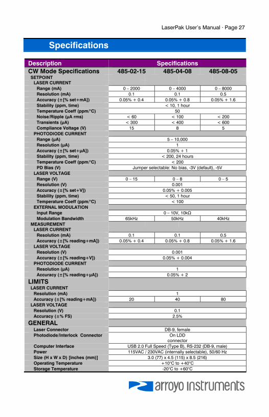
Description Specifications CW Mode Specifications 485-02-15 485-04-08 485-08-05 SETPOINT
LASER CURRENT Range (mA) 0 – 2000 0 – 4000 0 – 8000 Resolution (mA) 0.1 0.1 0.5 Accuracy (±[% set+mA]) 0.05% + 0.4 0.05% + 0.8 0.05% + 1.6 Stability (ppm, time) < 10, 1 hour Temperature Coeff (ppm/°C) 50 Noise/Ripple (μA rms) < 60 < 100 < 200 Transients (μA) < 300 < 400 < 600 Compliance Voltage (V) 15 8 5
PHOTODIODE CURRENT Range (μA) 5 – 10,000 Resolution (μA) 1 Accuracy (±[% set+μA]) 0.05% + 1 Stability (ppm, time) < 200, 24 hours Temperature Coeff (ppm/°C) < 200 PD Bias (V) Jumper selectable: No bias, -3V (default), -5V
LASER VOLTAGE Range (V) 0 – 15 0 – 8 0 – 5 Resolution (V) 0.001 Accuracy (±[% set+V]) 0.05% + 0.005 Stability (ppm, time) < 50, 1 hour Temperature Coeff (ppm/°C) < 100
EXTERNAL MODULATION Input Range 0 – 10V, 10kΩ Modulation Bandwidth 65kHz 50kHz 40kHz
MEASUREMENT LASER CURRENT
Resolution (mA) 0.1 0.1 0.5 Accuracy (±[% reading+mA]) 0.05% + 0.4 0.05% + 0.8 0.05% + 1.6
LASER VOLTAGE Resolution (V) 0.001 Accuracy (±[% reading+V]) 0.05% + 0.004
PHOTODIODE CURRENT Resolution (μA) 1 Accuracy (±[% reading+μA]) 0.05% + 2
LIMITS LASER CURRENT
Resolution (mA) 1 Accuracy (±[% reading+mA]) 20 40 80
LASER VOLTAGE Resolution (V) 0.1 Accuracy (±% FS) 2.5%
GENERAL
Laser Connector DB-9, female Photodiode/Interlock Connector On LDD
connector Computer Interface USB 2.0 Full Speed (Type B), RS-232 (DB-9, male) Power 115VAC / 230VAC (internally selectable), 50/60 Hz Size (H x W x D) [inches (mm)] 3.0 (77) x 4.5 (115) x 8.5 (216) Operating Temperature +10°C to +40°C Storage Temperature -20°C to +60°C
Page 28 · LaserPak User’s Manual
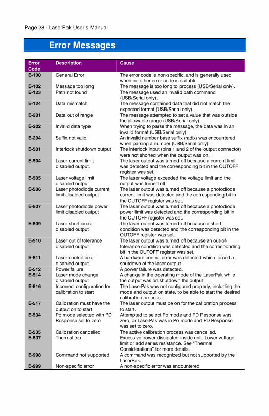
Error Messages
Error Code
Description Cause
E-100 General Error The error code is non-specific, and is generally used when no other error code is suitable.
E-102 Message too long The message is too long to process (USB/Serial only). E-123 Path not found The message used an invalid path command
(USB/Serial only). E-124 Data mismatch The message contained data that did not match the
expected format (USB/Serial only). E-201 Data out of range The message attempted to set a value that was outside
the allowable range (USB/Serial only). E-202 Invalid data type When trying to parse the message, the data was in an
invalid format (USB/Serial only). E-204 Suffix not valid An invalid number base suffix (radix) was encountered
when parsing a number (USB/Serial only). E-501 Interlock shutdown output The interlock input (pins 1 and 2 of the output connector)
were not shorted when the output was on. E-504 Laser current limit
disabled output. The laser output was turned off because a current limit was detected and the corresponding bit in the OUTOFF register was set.
E-505 Laser voltage limit disabled output
The laser voltage exceeded the voltage limit and the output was turned off.
E-506 Laser photodiode current limit disabled output
The laser output was turned off because a photodiode current limit was detected and the corresponding bit in the OUTOFF register was set.
E-507 Laser photodiode power limit disabled output
The laser output was turned off because a photodiode power limit was detected and the corresponding bit in the OUTOFF register was set.
E-509 Laser short circuit disabled output
The laser output was turned off because a short condition was detected and the corresponding bit in the OUTOFF register was set.
E-510 Laser out of tolerance disabled output
The laser output was turned off because an out-of-tolerance condition was detected and the corresponding bit in the OUTOFF register was set.
E-511 Laser control error disabled output
A hardware control error was detected which forced a shutdown of the laser output.
E-512 Power failure A power failure was detected. E-514 Laser mode change
disabled output A change in the operating mode of the LaserPak while the output was on shutdown the output.
E-516 Incorrect configuration for calibration to start
The LaserPak was not configured properly, including the mode and output on state, to be able to start the desired calibration process.
E-517 Calibration must have the output on to start
The laser output must be on for the calibration process to start.
E-534 Po mode selected with PD Response set to zero
Attempted to select Po mode and PD Response was zero, or LaserPak was in Po mode and PD Response was set to zero.
E-535 Calibration cancelled The active calibration process was cancelled. E-537 Thermal trip Excessive power dissipated inside unit. Lower voltage
limit or add series resistance. See “Thermal Considerations” for more details.
E-998 Command not supported A command was recognized but not supported by the LaserPak.
E-999 Non-specific error A non-specific error was encountered.
LaserPak User’s Manual · Page 29
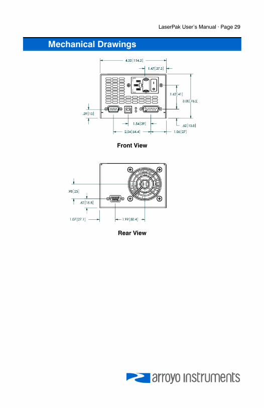
Mechanical Drawings
Front View
Rear View
Page 30 · LaserPak User’s Manual
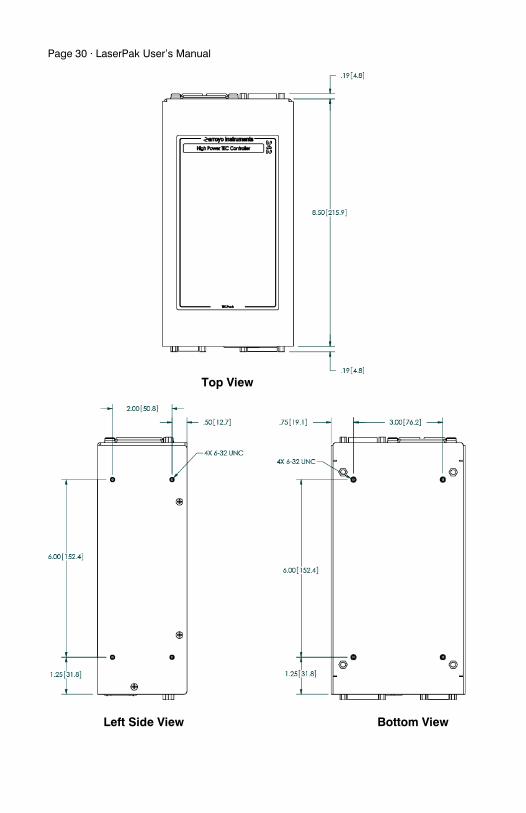
Top View
Left Side View Bottom View
LaserPak User’s Manual · Page 31
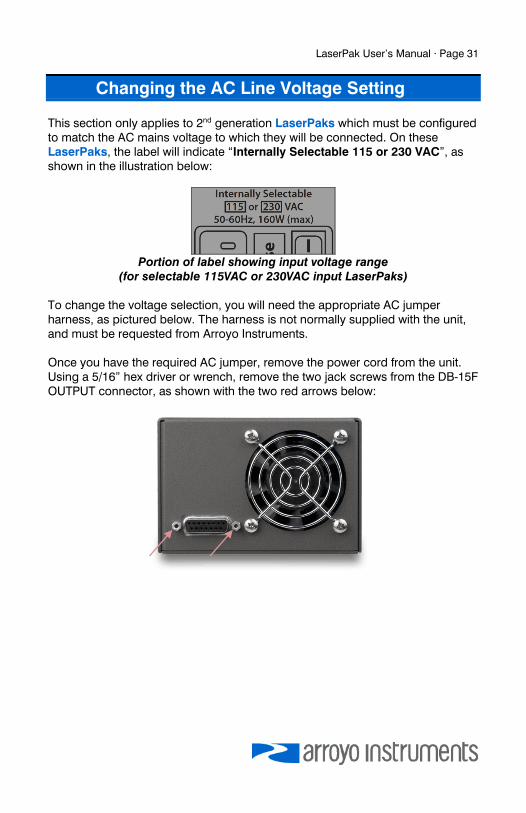
Changing the AC Line Voltage Setting
This section only applies to 2nd generation LaserPaks which must be configured to match the AC mains voltage to which they will be connected. On these LaserPaks, the label will indicate “Internally Selectable 115 or 230 VAC”, as shown in the illustration below:
Portion of label showing input voltage range
(for selectable 115VAC or 230VAC input LaserPaks) To change the voltage selection, you will need the appropriate AC jumper harness, as pictured below. The harness is not normally supplied with the unit, and must be requested from Arroyo Instruments. Once you have the required AC jumper, remove the power cord from the unit. Using a 5/16” hex driver or wrench, remove the two jack screws from the DB-15F OUTPUT connector, as shown with the two red arrows below:
Page 32 · LaserPak User’s Manual
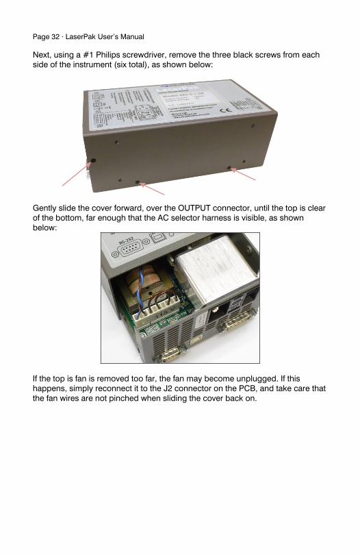
Next, using a #1 Philips screwdriver, remove the three black screws from each side of the instrument (six total), as shown below:
Gently slide the cover forward, over the OUTPUT connector, until the top is clear of the bottom, far enough that the AC selector harness is visible, as shown below:
If the top is fan is removed too far, the fan may become unplugged. If this happens, simply reconnect it to the J2 connector on the PCB, and take care that the fan wires are not pinched when sliding the cover back on.
LaserPak User’s Manual · Page 33
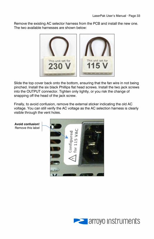
Remove the existing AC selector harness from the PCB and install the new one. The two available harnesses are shown below:
Slide the top cover back onto the bottom, ensuring that the fan wire in not being pinched. Install the six black Phillips flat head screws. Install the two jack screws into the OUTPUT connector. Tighten only lightly, or you risk the change of snapping off the head of the jack screw. Finally, to avoid confusion, remove the external sticker indicating the old AC voltage. You can still verify the AC voltage as the AC selection harness is clearly visible through the vent holes.
Avoid confusion!Remove this label
Page 34 · LaserPak User’s Manual
Maintenance and Service
Maintenance The LaserPak requires no regular maintenance other than product calibration. To clean the instrument, use cotton cloth that is only damp (not wet) with a light solution of soap and water. Fuses Under normal operation, you should never need to replace a fuse. However, if either fuse does blow, use only T 250V, IEC 60127-2 5x20mm metric fuses with a current rating as specified on the unit as replacements. If, after replacing the fuse, it continues to blow, immediately discontinue use of the instrument and contact service for support. Service Service and repair for the LaserPak can be obtained by contacting the distributor from where you purchased the instrument, or directly from Arroyo Instruments. A complete list of distributors is available on the Arroyo Instruments web site. You can contact Arroyo Instruments through one of these methods: By mail: Arroyo Instruments
624 Clarion Court San Luis Obispo, CA 93401 USA
By phone: +1 (805) 543-1302
By fax: +1 (805) 543-1303
By email: [email protected]
On the web: http://www.arroyoinstruments.com In all cases, Arroyo Instruments requires a return materials authorization (RMA) number. You must contact Arroyo Instruments and obtain an RMA number prior to returning your instrument, or the shipment may be rejected and sent back to you.
LaserPak User’s Manual · Page 35
European Community Declaration of Conformity
EC Declaration of Conformity
I/We
Arroyo Instruments of
624 Clarion Court San Luis Obispo, CA 93401 USA
declare that 485 Series LaserPak Laser Diode Driver
In accordance with the following directives
EMC Directive: 89/336/EEC Low Voltage Directive: 73/23/EEC RoHS Directive: 2002/95/EC89/336/EEC
has been designed and manufactured to the following specifications:
EMC Directive Test Standards EN 61326 Electrical Equipment for Measurement, Control and Laboratory Use EMC
Requirements. This encompasses 10 individual Tests Low Voltage Directive Test Standards EN 61010 Electrical Equipment for Measurement, Control and Laboratory Use
Safety Requirements. This Certificate is the Manufacturer’s Declaration which states that the 485 Series LaserPak Laser Diode Driver is Compliant to the above noted EU Directives and are therefore, eligible to bear the CE MARK. This equipment, as of the listed Date of Manufacture, is technically exempted from the RoHS Directive Requirements, not being classified as consumer electronics equipment.
I hereby declare that the equipment named above has been designed to comply with the relevant sections of the above referenced specifications. The unit complies with all essential requirements of the Directives.
Paul Corr (NAME OF AUTHORIZED PERSON) (SIGNATURE OF AUTHORIZED PERSON)
President 1 February 2010 (TITLE OF AUTHORIZED PERSON) (DATE OF ISSUE)

Copyright © 2011, Arroyo Instruments. All Rights Reserved P/N 530-1022E