Embed Size (px)
Citation preview
for use by heating contractor
Please file in Service Binder
Read and save these instructions for future reference.
IMPORTANT
Product may not be exactly as shown
5285 429 - 06 09/2016
Installation Instructions
VITOROND 200
Vitorond 200VD2 SeriesOil-/Gas-fired boilerHeating input: 1255 to 4387 MBH (368 to 1285 kW)
Working on the equipmentThe installation, adjustment, service andmaintenance of this product must be performedby a licensed professional heating contractor,who is qualified and experienced in the installation, service and maintenance of hot water heating boilers. There are no user serviceable parts on the boiler, burner, or control.Ensure main power supply to equipment, theheating system and all external controls has beendeactivated. Close main oil or gas supply valve.Take precautions in all instances to avoidaccidental activation of power during service work.Improper installation, service or maintenance cancause product/property damage, severe personalinjury, and/or loss of life.
IMPORTANTPlease ensure that these instructions are read andunderstood before commencing installation and start-up. Failure to comply with these Installation Instructions will render all warranties null and void.
Vitorond 200, VD2 Series 320 to 1080 Installation
5285 4
29 -
06
2
Safety, Installation and Warranty RequirementsSafety
Please ensure that these instructions are read and understood before commencing installation. Failure to comply with the instructions listed below and details printed in this manual can cause product/property damage, severe personal injury, and/or loss of life. Ensure all requirements below are understood and fulfilled (including detailed information found in manual subsections).
WARNINGInstallers must follow local regulations with respect to installation of carbon monoxide detectors. Follow the Viessmann maintenance schedule of the boiler in the “Service Instructions” manual.
Product documentation Read all applicable documentation before commencing installation. Store documentation near boiler in a readily accessible location for reference in the future by service personnel.
For a listing of applicable literature, please see section entitled “Important Regulatory and Safety Requirements”.
Licensed professional heating contractor The installation, adjustment, service and maintenance of this equipment must be performed by a licensed professional heating contractor.
Please see section entitled “Important Regulatory and Installation Requirements”.
Contaminated air Air contaminated by chemicals can cause by-products in the combustion process, which are poisonous to inhabitants and destructive to Viessmann equipment.
For a listing of chemicals which cannot be stored in or near the boiler room, please see section entitled “Mechanical Room”. in this manual.
Advice to owner Once the installation work is complete, the heating contractor must familiarize the system operator/ ultimate owner with all equipment, as well as safety precautions/requirements, shutdown procedure, and the need for professional service annually before the heating season begins.
Warranty Information contained in this and related product documentation must be read and followed. Failure to do so renders the warranty null and void.
Carbon monoxide Improper installation, adjustment, service and/or maintenance can cause flue products to flow into living space. Flue products contain poisonous carbon monoxide gas.
For information pertaining to the proper installation, adjustment, service and maintenance of this equipment to avoid formation of carbon monoxide, please see section entitled “Combustion air supply” and “Venting information” in this manual.
Fresh air This equipment requires fresh air for safe operation and must be installed ensuring provisions for adequate combustion and ventilation air exist.
For information pertaining to the fresh air requirements of this product, please see subsection entitled “Mechanical Room” in this manual.
Equipment venting Never operate boiler without an installed venting system. An improper venting system can cause carbon monoxide poisoning.
For information pertaining to venting and chimney requirements, please see section entitled “Venting Information” in this manual. All products of combustion must be safely vented to the outdoors.
3
5285 4
29 -
06
Vitorond 200, VD2 Series 320 to 1080 Installation Safety Safety, Installation and Warranty Requirements (continued)
WARNINGInhaling of fiberglass wool and/or ceramic fiber materials is a possible cancer hazard. These materials can also cause respiratory, skin and eye irritation.
H Fiberglass wool and ceramic fiber materials
WARNINGAppliance materials of construction, products of combustion and the fuel contain alumina, silica, heavy metals, carbon monoxide, nitrogen oxides, aldehydes and/or other toxic or harmful substances which can cause serious injury or loss of life and which are known to the State of California to cause cancer, birth defects and other reproductive harm. Always use proper safety clothing, respirators and equipment when servicing or working nearby the appliance.
The state of California has listed the airborne fibers of these materials as a possible cancer hazard through inhalation. When handling these materials, special care must be applied.
Suppliers of fiberglass wool products recommend the following precautions be taken when handling these materials:
Precautionary measures
- Avoid breathing fiberglass dust and contact with skin and eyes.- Use NIOSH approved dust/mist respirator.- Wear long-sleeved, loose fitting clothing, gloves and eye protection.
- Wash work clothes separately from other clothing. Rinse washer thoroughly.- Operations such as sawing, blowing, tear-out and spraying may generate airborne fiber concentration requiring additional protection.
First aid measures
- If eye contact occurs, flush eyes with water to remove dust. If symptoms persist, seek medical attention.
- If skin contact occurs, wash affected areas gently with soap and warm water after handling.
H Hazardous materials
Suppliers of ceramic fiber products recommend the following first aid measures:
- Respiratory tract (nose and throat) irritation: If respiratory tract irritation develops, move the person to a dust free location.
- Eye irritation: If eyes become irritated, flush immediately with large amounts of lukewarm water for at least 15 minutes. Eyelids should be held away from the eyeball to ensure thorough rinsing. Do not rub eyes.
- Skin irritation: If skin becomes irritated, remove soiled clothing. Do not rub or scratch exposed skin. Wash area of contact thoroughly with soap and water. Using a skin cream or lotion after washing may be helpful.
- Gastrointestinal irritation: If gastrointestinal tract irritation develops, move the person to a dust free environment.
4
Page
Table of Contents
5285 4
29 -
06
Vitorond 200, VD2 Series 320 to 1080 Installation
Safety
General Information
Set-up
Assembly
Safety, Installation and Warranty Requirements ..............2
Product documentation ...........................................2Licensed professional heating contractor ...................2Contaminated air ...................................................2Advice to owner ....................................................2Warranty ..............................................................2Carbon monoxide ...................................................2Fresh air ...............................................................2Equipment venting .................................................2Fiberglass wool and ceramic fiber materials ...............3Suppliers of ceramic fiber products recommend the following first aid measures:....................................3Precautionary measures ..........................................3First aid measures ..................................................3Hazardous materials ...............................................3
Important Regulatory and Safety Requirements ..............7
Codes ..................................................................8Mechanical room ...................................................8Working on the equipment ......................................8Technical literature ................................................8Installation tools and materials .................................8
About these Installation Instructions .............................9
Product Information ....................................................9
Mechanical Room .....................................................10
Minimum Clearances .................................................10
Minimum Clearances to Combustibles ....................10Boiler model VD2 .................................................10Recommended Minimum Service Clearances ...........10
Boiler Set-up and Location .........................................11
Transport into mechanical room .............................11Foundation ..........................................................11
Standard Equipment .................................................12
Number of cast iron sections per model ..................12
Cast Iron Section Assembly .......................................13
Boiler Model VD2.................................................16Number of sections ..............................................16Tie rod layout 19 and 24 in. (480 and 610 mm) ......16
Water Distribution Pipe and Drain Installation ...............17
Hydrostatic Pressure Test ..........................................18
Flue Gas Turbulators and Combustion Chamber Door ....19
5
Page
Table of Contents5285 4
29 -
06
Vitorond 200, VD2 Series 320 to 1080 Installation
Connections
Enclosure
Burner
Water Side Connections ............................................20
Return temperature elevation .................................21
Venting Connection ..................................................22
In Canada ...........................................................22In U.S.A. ............................................................22
Venting Requirements ...............................................22
Venting option #1 (Category I venting) ...................22Chimney .............................................................22Barometric draft regulator type ..............................23Barometric draft regulator diameter ........................23Venting option #1 (Category I venting) ...................22Venting option #2 (Category III) .............................24ProTech Systems Inc. ...........................................24Selkirk Metalbestos ..............................................24Security Chimneys ...............................................24
Flue Gas Connection .................................................24
Flue gas test point location ...................................24
Removal of Existing Boiler .........................................25
Safety Connections and Pressure Testing ....................26
Pressure relief valve .............................................26
Boiler Pressure Test ..................................................26
Low Water Cut-off (LWCO) .......................................26
Enclosure Installation ................................................27
Boiler model VD2 .................................................27
Boiler Control Installation ...........................................31
Enclosure Installation ................................................32
Burner Installation ....................................................33
Combustion chamber sight glass ............................33Fuels ..................................................................33Burner calibration .................................................34Two-stage burner ................................................34Model .................................................................34Flue gas resistance ..............................................34Fully modulating burner ........................................34Weishaupt burners / Riello burners .........................34Vitorond 200, VD2 with Viessmann / Vitotronic controls ..............................................................34Model .................................................................34Input ..................................................................34Min.1-stage .........................................................34
6
Page
Table of Contents
5285 4
29 -
06
Vitorond 200, VD2 Series 320 to 1080 Installation
Start-up
Appendix
System Preparation ..................................................35
Combustion air supply ..........................................35Gas piping pressure test .......................................35
Initial System Fill ......................................................35
Prior to Start-up .......................................................36
Start-up Information .................................................37
Initial start-up ......................................................37Instructing the system user ...................................37Shut-down ..........................................................37Extended shut-down periods .................................37Start-up after extended shut-down .........................37
Piping in Heating/Cooling Application ..........................38
Technical Data .........................................................39
Technical Data ....................................................39Boiler Model ........................................................39Input (oil) ............................................................39Input (gas) ..........................................................39Output (oil/gas) ...................................................39Combustion efficiency (oil) ...................................39Combustion efficiency (gas) .................................39Thermal efficiency (oil) .........................................39Thermal efficiency (gas) .......................................39Number of cast iron sections .................................39Cast iron block dimensions ....................................39Cast iron section dimensions .................................39Technical Data.....................................................40Boiler Model.........................................................40Dimensions (with insul. jacket) .............................40Weight ...............................................................40Overall weight .....................................................40Boiler water content .............................................40Max. boiler temperature ........................................... 40Max. allow. operating pressure ..............................40Boiler connections ................................................41Heating surface area ............................................41Flue gas .............................................................41Vent pipe collar ..................................................41Flue gas resistance - at upper end of rated input ......41Required flue draft Category I ................................41Positive pressure Category III ................................41
7
5285 4
29 -
06
Vitorond 200, VD2 Series 320 to 1080 Installation Safety Important Regulatory and Safety Requirements
For installations on the Commonwealth of Massachusetts, the following modifications to NFPA-54 chapter 10 apply:
Excerpt from 248 CMR 5-08:
2(a) For all side-wall horizontally vented gas fueled equipment installed in every dwelling, building or structure used in whole or in part for residential purposes, including those owned or operated by the Commonwealth and where the side-wall exhaust vent termination is less than (7) feet above finished grade in the area of the venting, including but not limited to decks and porches, the following requirements shall be satisfied:
1. INSTALLATION OF CARBON MONOXIDE DETECTORS. At the time of installation of the side-wall horizontal vented gas fueled equipment, the installing plumber or gas fitter shall observe that a hard wired carbon monoxide detector with an alarm and battery back-up is installed on the floor level where the gas equipment is to be installed. In addition, the installing plumber or gas fitter shall observe that a battery operated or hard wired carbon monoxide detector with an alarm is installed on each additional level of the dwelling, building or structure served by the side-wall horizontal vented gas fueled equipment. It shall be the responsibility of the property owner to secure the services of qualified licensed professional for the installation of hard-wired carbon monoxide detectors.
a. In the event that the side-wall horizontally vented gas fueled equipment is installed in a crawl space or an attic, the hard-wired carbon monoxide detector with alarm and battery back-up may be installed on the next adjacent floor level.
b. In the event that the requirements of this subdivision can not be met at the time of completion of installation, the owner shall have a period of thirty (30) days to comply with the above requirements; provided, however, that during said thirty (30) day period, a battery operated carbon monoxide detector with an alarm shall be installed.
2. APPROVED CARBON MONOXIDE DETECTORS. Each carbon monoxide detector as required in accordance with the above provisions shall comply with NFPA 720 and be ANSI/UL 2034 listed and IAS certified.
3. SIGNAGE. A metal or plastic identification plate shall be permanently mounted to the exterior of the building at a minimum height of eight (8) feet above grade directly in line with the exhaust vent terminal for the horizontally vented gas fueled heating appliance or equipment. The sign shall read, in print size no less than one-half (b) inch in size, "GAS VENT DIRECTLY BELOW. KEEP CLEAR OF ALL OBSTRUCTIONS".
4. INSPECTION. The state or local gas inspector of the side-wall horizontally vented gas fueled equipment shall not approve the installation unless, upon inspection, the inspector observes carbon monoxide detectors and signage installed in accordance with the provisions of 248 CMR 5.08(2)(a) 1 through 4.
(b) EXEMPTIONS: The following equipment is exempt from 248 CMR 5.08(2)(a) 1 through 4:
1. The equipment listed in Chapter 10 entitled "Equipment Not Required To Be Vented" in the most current edition of NFPA 54 as adopted by the Board; and
2. Product Approved side-wall horizontally vented gas fueled equipment installed in a room or structure separate from the dwelling, building or structure used in whole or in part for residential purposes.
Vitorond 200, VD2 Series 320 to 1080 Installation
5285 4
29 -
06
8
Safety Important Regulatory and Safety Requirements (continued)
Codes
The installation of this unit shall be in accordance with local codes. In the absence of local codes, use:CAN/CSA-B149.1 or .2 InstallationCodes for Gas Burning Appliances for Canada. For U.S. installations, use the National Fuel Gas Code ANSI Z223.1. Always use latest editions of codes.
For oil-fired boiler installation, use CSA B-139 in Canada and NFPA 31 in the U.S. Always use latest editions of codes.
In Canada all electrical wiring is to be done in accordance with the latest edition of CSA C22.1 Part 1 and/or local codes. In the U.S., use the National Electrical Code ANSI/NFPA 70.
The heating contractor must also comply with the Standard for Controls and Safety Devices for Automatically Fired Boilers, ANSI/ASME CSD-1 where required by the authority having jurisdiction.Note: Please carefully read this manual prior to attempting
installation. Any warranty is null and void if these instructions are not followed.
For information regarding other Viessmann System Technology componentry, please reference documentation of the respective product.
We offer frequent installation and service seminars to familiarize our partners with our products. Please inquire.
Mechanical room
Ensure the mechanical room complies with the requirements of the System Design Guidelines and/or Technical Data Manual. In addition, see section entitled “Mechanical Room” on page 7 in this manual.
Viessmann recommends installation of an additional electrical disconnect switch and a fuel shut-off valve (if possible) outside the mechanical room or enclosed area of installation.
The maximum room temperature of the mechanical room where the boiler is located must not exceed 104°F ( 40°C).
Working on the equipment
The installation, adjustment, service, and maintenance of this boiler must be performed by a licensed professional heating contractor who is qualified and experienced in the installation, service, and maintenance of hot water boilers. There are no user serviceable parts on the boiler, burners, or control.Note: The completeness and functionality of field supplied
electrical controls and components must be verified by the heating contractor. This includes low water cut-offs, flow switches (if used), staging controls, pumps, motorized valves, air vents, thermostats, etc.
Ensure main power supply to equipment, the heating system, and all external controls has been deactivated. Close main gas supply valve. Take precautions in all instances to avoid accidental activation of power during service work.
Technical literature
Literature for the Vitocrossal 200 VD2 boiler:- Technical Data Manual- Installation Instructions- Service Instructions- Operating Instructions and User’s Information Manual- Instructions of other Viessmann products utilized with
this installation- Installation codes mentioned in this manual
For installation of the heating system, refer to the technical literature of other System Technology devices:- Installation Instructions for Viessmann boiler control- Installation Instructions for Viessmann indirect-fired hot water storage tank(s)- Installation Instructions for burner and accessoriesNote: Leave all literature at the installation site and advise
the system operator/ultimate owner where the literature can be found. Contact Viessmann for additional copies.
Installation tools and materials
In addition to standard tools and safety wear typically necessary to install the boiler, the following are needed to perform the assembly of this cast iron sectional boiler:- draw tool kit- wood/rubber mallet and regular hammer- half-round metal file- flat chisel- lacquer solvent- linseed oil- cleaning rags
9
5285 4
29 -
06
Vitorond 200, VD2 Series 320 to 1080 Installation General Information
Product Information
Sectional cast iron oil-/gas-fired hot water heating boiler.
For operation with modulating boiler water temperatures in closed loop, forced circulation hot water heating systems.
The Vitorond 200, VD2 boilers are Category I boilers as defined by the ANSI 21.13/CSA 4.9-2000. See the “Venting Connection” section in this manual for detailed information.
The boiler model selected should be based on an accurate heat loss calculation of the building. The boiler selected must be compatible with the connected radiation.
Maximum working pressure. . . . . . . . . . 75 psig (5 bar)Minimum working pressure. . . . . . .. . . .20 psig (1.5 bar)Maximum boiler temperature. . . . . . . . . 248°F (120°C)
This boiler does not require a flow switch.
WARNINGExposing the boiler to pressures and temperatures in excess of those listed will result in damages, and will render warranty null and void.
About these Installation Instructions
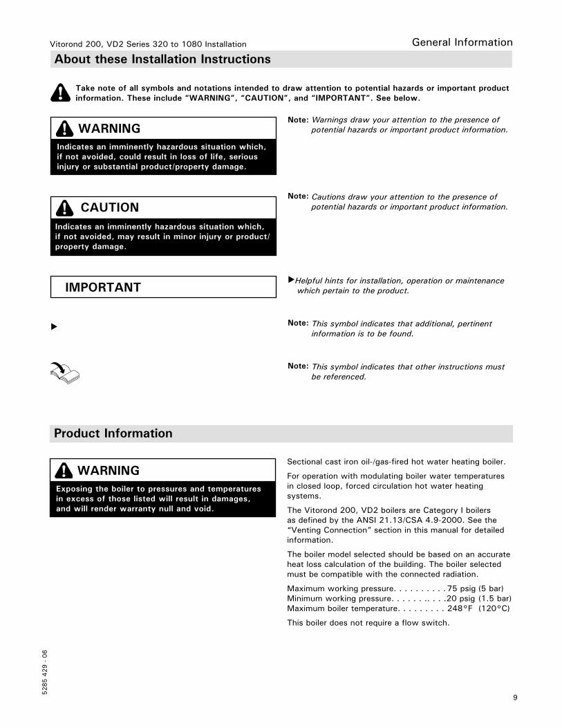
Take note of all symbols and notations intended to draw attention to potential hazards or important product information. These include “WARNING”, “CAUTION”, and “IMPORTANT”. See below.
IMPORTANT
Note: Warnings draw your attention to the presence of potential hazards or important product information.
Note: Cautions draw your attention to the presence of potential hazards or important product information.
Helpful hints for installation, operation or maintenance which pertain to the product.
Note: This symbol indicates that additional, pertinent information is to be found.
Note: This symbol indicates that other instructions must be referenced.
WARNINGIndicates an imminently hazardous situation which,if not avoided, could result in loss of life, serious injury or substantial product/property damage.
CAUTIONIndicates an imminently hazardous situation which, if not avoided, may result in minor injury or product/property damage.
Vitorond 200, VD2 Series 320 to 1080 Installation
5285 4
29 -
06
10
Mechanical Room
Boiler must be located in a heated indoor space. The Vitorond 200, VD2 boiler should be located near a floor drain and as close as possible to the vertical chimney or vent.
Whenever possible, install boiler near an outside wall so that it is easy to duct fresh air directly to the boiler area.
Install boiler on flooring capable of supporting the weight of the boiler filled with water.
Set-up
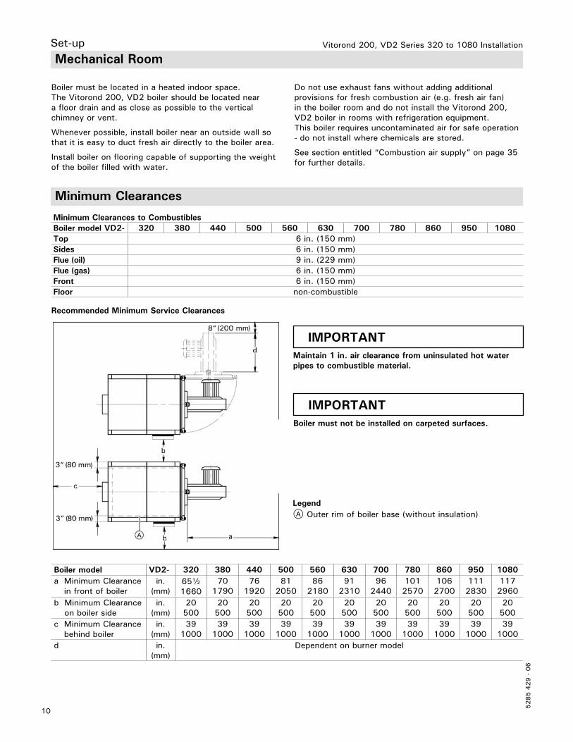
Minimum Clearances
LegendA Outer rim of boiler base (without insulation)
Minimum Clearances to CombustiblesBoiler model VD2- 320 380 440 500 560 630 700 780 860 950 1080Top 6 in. (150 mm)Sides 6 in. (150 mm)Flue (oil) 9 in. (229 mm)Flue (gas) 6 in. (150 mm)Front 6 in. (150 mm)Floor non-combustible
IMPORTANTMaintain 1 in. air clearance from uninsulated hot water pipes to combustible material.
Recommended Minimum Service Clearances
Boiler model VD2- 320 380 440 500 560 630 700 780 860 950 1080a Minimum Clearance
in front of boilerin.
(mm)65b1660
701790
761920
812050
862180
912310
962440
1012570
1062700
1112830
1172960
b Minimum Clearance on boiler side
in. (mm)
20500
20500
20500
20500
20500
20500
20500
20500
20500
20500
20500
c Minimum Clearance behind boiler
in. (mm)
391000
391000
391000
391000
391000
391000
391000
391000
391000
391000
391000
d in. (mm)
Dependent on burner model
IMPORTANTBoiler must not be installed on carpeted surfaces.
Do not use exhaust fans without adding additional provisions for fresh combustion air (e.g. fresh air fan) in the boiler room and do not install the Vitorond 200, VD2 boiler in rooms with refrigeration equipment. This boiler requires uncontaminated air for safe operation - do not install where chemicals are stored.
See section entitled “Combustion air supply” on page 35 for further details.
11
5285 4
29 -
06
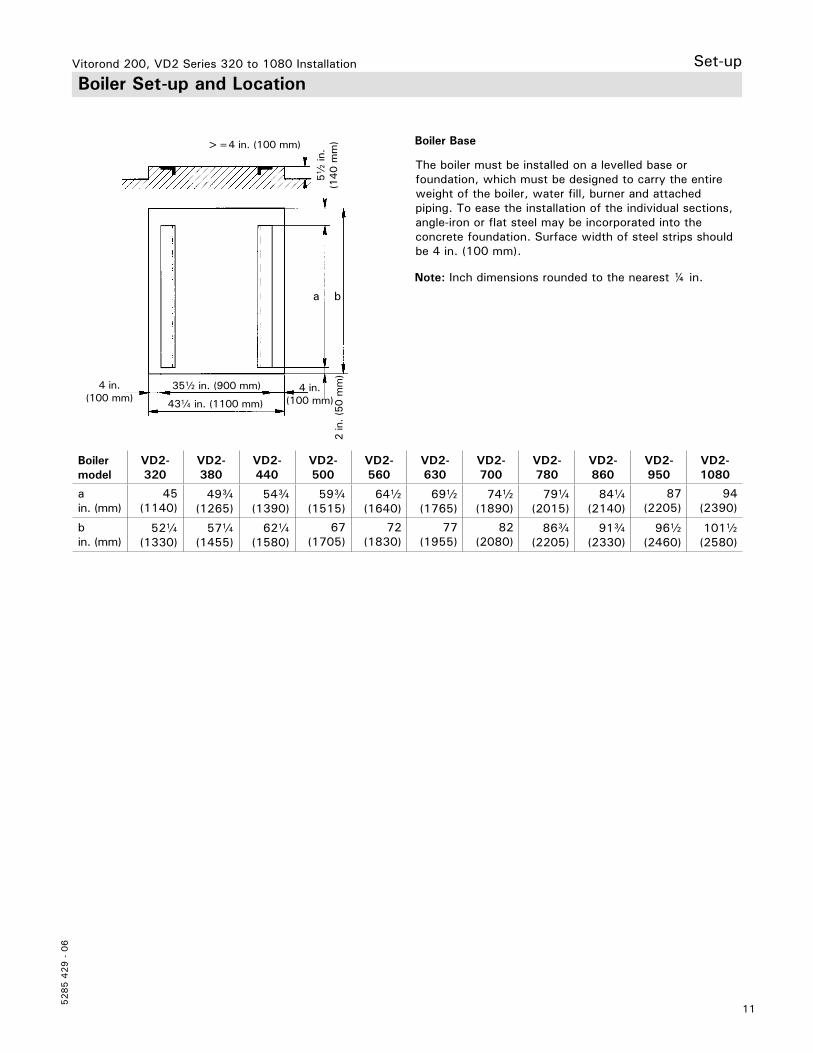
Vitorond 200, VD2 Series 320 to 1080 Installation Set-up Boiler Set-up and Location
Boiler model
VD2-320
VD2-380
VD2-440
VD2-500
VD2-560
VD2-630
VD2-700
VD2-780
VD2-860
VD2-950
VD2-1080
ain. (mm)
45(1140)
49c(1265)
54c(1390)
59c(1515)
64b(1640)
69b(1765)
74b(1890)
79a(2015)
84a(2140)
87(2205)
94(2390)
bin. (mm)
52a(1330)
57a(1455)
62a(1580)
67(1705)
72(1830)
77(1955)
82(2080)
86c(2205)
91c(2330)
96b(2460)
101b(2580)
The boiler must be installed on a levelled base or foundation, which must be designed to carry the entire weight of the boiler, water fill, burner and attached piping. To ease the installation of the individual sections, angle-iron or flat steel may be incorporated into the concrete foundation. Surface width of steel strips should be 4 in. (100 mm).
Boiler Base>=4 in. (100 mm)
35b in. (900 mm)
43a in. (1100 mm)
2 in
. (5
0 m
m)
4 in. (100 mm)
4 in. (100 mm)
5b
in.
(140 m
m)
a b
Note: Inch dimensions rounded to the nearest ¼ in.

Vitorond 200, VD2 Series 320 to 1080 Installation
5285 4
29 -
06
12
Set-up Standard Equipment
LegendA Combustion chamber doorB Front sectionC Intermediate sectionD Rear sectionE Flue gas collar
Number of cast iron sections per model
Boiler model VD2- 320 380 440 500 560 630 700 780 860 950 1080
Total number of sections
9 10 11 12 13 14 15 16 17 18 19
Number of intermediate sections
7 8 9 10 11 12 13 14 15 16 17
All necessary parts to assemble the heating boiler are packaged and shipped in the carton labeled “Boiler Accessories”.
The heat exchanger block consists of a rear section with mounted flue gas collar, a front section with mounted combustion chamber door, and depending on the size of the boiler, the appropriate number of intermediate sections.
Individual cast iron sections are sealed by inserting glass fiber rope gaskets which are glued into the pre-cast groove system on each section to seal the flue gas passageways.
The water side seal between the sections is achieved with cast iron push nipples.
IMPORTANTObserve directional arrows on cast iron sections. See Fig. 3, as well as step 7 on the following page.
Boiler front
13
5285 4
29 -
06
Vitorond 200, VD2 Series 320 to 1080 Installation Cast Iron Section Assembly
Assembly
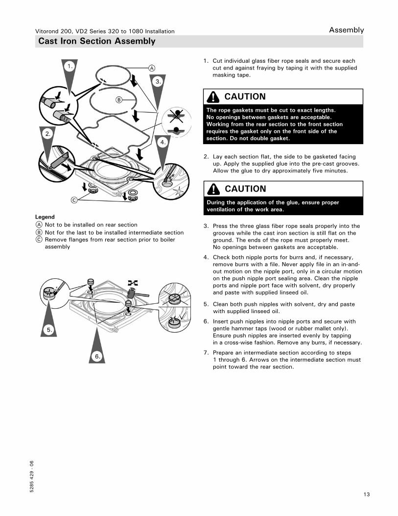
3. Press the three glass fiber rope seals properly into the grooves while the cast iron section is still flat on the ground. The ends of the rope must properly meet. No openings between gaskets are acceptable.
4. Check both nipple ports for burrs and, if necessary, remove burrs with a file. Never apply file in an in-and-out motion on the nipple port, only in a circular motion on the push nipple port sealing area. Clean the nipple ports and nipple port face with solvent, dry properly and paste with supplied linseed oil.
5. Clean both push nipples with solvent, dry and paste with supplied linseed oil.
6. Insert push nipples into nipple ports and secure with gentle hammer taps (wood or rubber mallet only). Ensure push nipples are inserted evenly by tapping in a cross-wise fashion. Remove any burrs, if necessary.
7. Prepare an intermediate section according to steps 1 through 6. Arrows on the intermediate section must point toward the rear section.
LegendA Not to be installed on rear sectionB Not for the last to be installed intermediate sectionC Remove flanges from rear section prior to boiler
assembly
CAUTIONThe rope gaskets must be cut to exact lengths. No openings between gaskets are acceptable. Working from the rear section to the front section requires the gasket only on the front side of the section. Do not double gasket.
CAUTIONDuring the application of the glue, ensure proper ventilation of the work area.
1. Cut individual glass fiber rope seals and secure each cut end against fraying by taping it with the supplied masking tape.
2. Lay each section flat, the side to be gasketed facing up. Apply the supplied glue into the pre-cast grooves. Allow the glue to dry approximately five minutes.
Vitorond 200, VD2 Series 320 to 1080 Installation
5285 4
29 -
06
14
Assembly Cast Iron Section Assembly (continued)
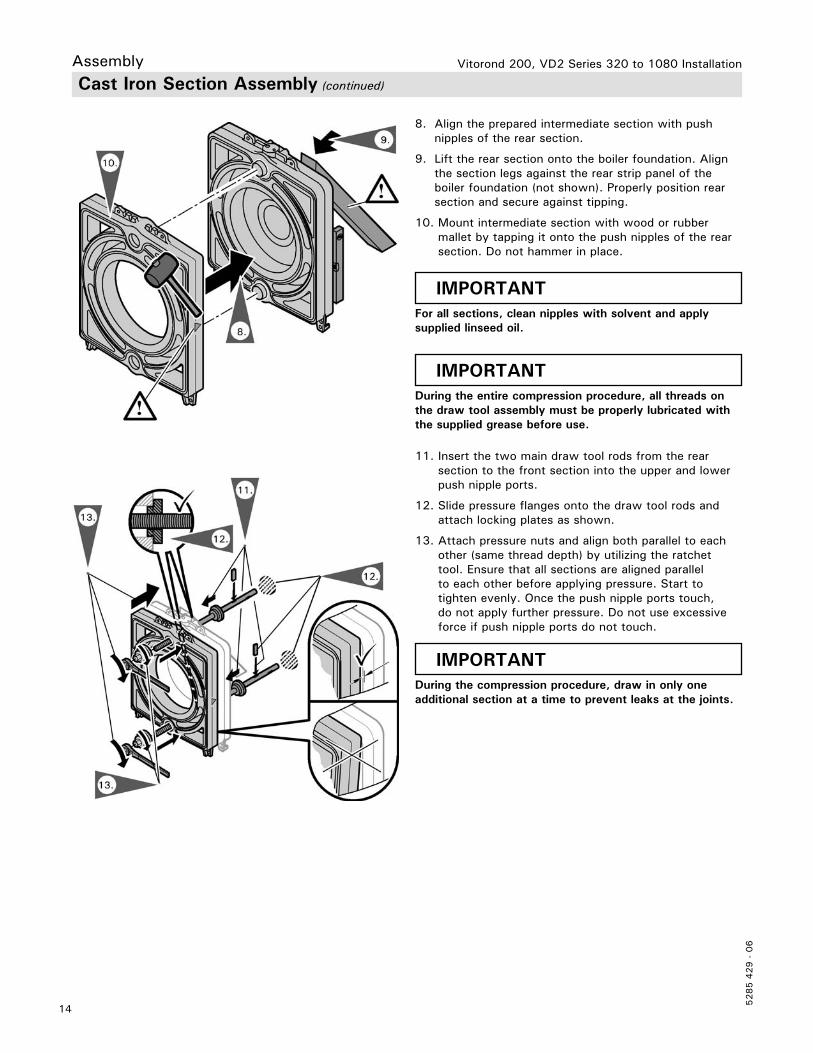
IMPORTANTFor all sections, clean nipples with solvent and apply supplied linseed oil.
IMPORTANTDuring the entire compression procedure, all threads on the draw tool assembly must be properly lubricated with the supplied grease before use.
8. Align the prepared intermediate section with push nipples of the rear section.
9. Lift the rear section onto the boiler foundation. Align the section legs against the rear strip panel of the boiler foundation (not shown). Properly position rear section and secure against tipping.
10. Mount intermediate section with wood or rubber mallet by tapping it onto the push nipples of the rear section. Do not hammer in place.
11. Insert the two main draw tool rods from the rear section to the front section into the upper and lower push nipple ports.
12. Slide pressure flanges onto the draw tool rods and attach locking plates as shown.
13. Attach pressure nuts and align both parallel to each other (same thread depth) by utilizing the ratchet tool. Ensure that all sections are aligned parallel to each other before applying pressure. Start to tighten evenly. Once the push nipple ports touch, do not apply further pressure. Do not use excessive force if push nipple ports do not touch.
IMPORTANTDuring the compression procedure, draw in only one additional section at a time to prevent leaks at the joints.

15
5285 4
29 -
06
Vitorond 200, VD2 Series 320 to 1080 Installation Cast Iron Section Assembly (continued)
Assembly
14. Loosen draw tool and remove pressure nuts.
15. Repeat steps 1 through 10 until the draw tool kit can be used again. Do not glue glass fiber rope into center of pre-cast groove of intermediate section attached to front section (see page 10).
16. Attach extension rods to the main draw rods and sections according to steps 11 and 12, until heat exchanger block is completely assembled.
17. Remove supports after three sections have been assembled.
18. Remove combustion chamber door from front section by loosening threaded M 16 nuts.
19. Prepare front section in the same way as previous sections and align with remainder of heat exchanger block utilizing the draw tool kit in the same fashion as before.
20. Tie rods with washers to top and bottom of heat exchanger block according to pattern and table on following page. Space threads on front and rear sections evenly. Do not overtighten.
21. Loosen pressure nuts and remove draw tool kit. Retighten all tie rods.
IMPORTANTOnly release the draw tool once the sections have been joined with the tie rods.
22. Ensure that the heat exchanger block is level and vertical on boiler base. All individual section legs must properly rest on boiler foundation. Where necessary, fill gaps with strips of sheet metal.
Please clean draw tool kit before re-crating, ensure that all parts are included and crate is properly closed before return shipment.
IMPORTANTAll section feet must be firmly placed on the boiler base. If necessary, shim section feet.
Vitorond 200, VD2 Series 320 to 1080 Installation
5285 4
29 -
06
16
Assembly Cast Iron Section Assembly (continued)
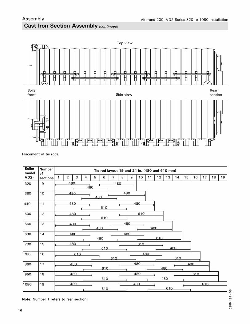
Top view
Side viewRear section
Boiler front
Placement of tie rods
Note: Number 1 refers to rear section.
Tie rod layout 19 and 24 in. (480 and 610 mm)Number of sections
Boiler model VD2-
17
5285 4
29 -
06
Vitorond 200, VD2 Series 320 to 1080 Installation Assembly Water Distribution Pipe and Drain Installation
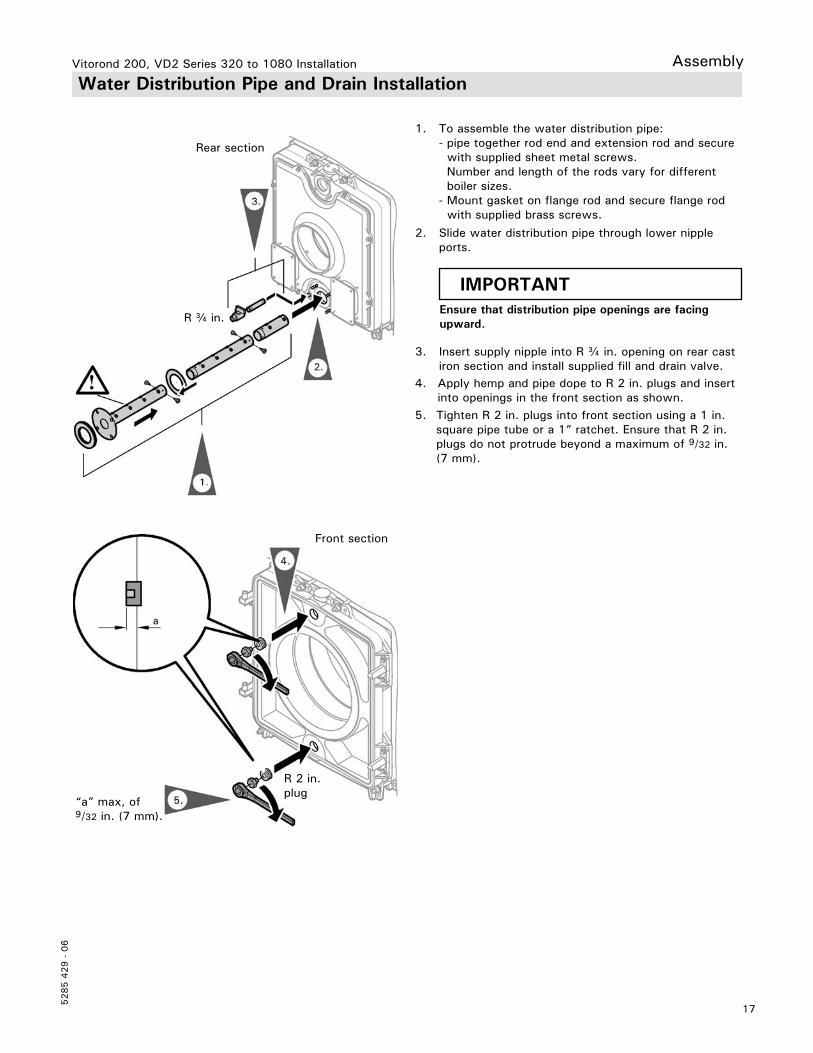
1. To assemble the water distribution pipe: - pipe together rod end and extension rod and secure with supplied sheet metal screws. Number and length of the rods vary for different boiler sizes. - Mount gasket on flange rod and secure flange rod with supplied brass screws.
2. Slide water distribution pipe through lower nipple ports.
3. Insert supply nipple into R c in. opening on rear cast iron section and install supplied fill and drain valve.
IMPORTANTEnsure that distribution pipe openings are facing upward.
Front section
“a” max, of 9/32 in. (7 mm).
R 2 in. plug
Rear section
R c in.
4. Apply hemp and pipe dope to R 2 in. plugs and insert into openings in the front section as shown.5. Tighten R 2 in. plugs into front section using a 1 in. square pipe tube or a 1” ratchet. Ensure that R 2 in. plugs do not protrude beyond a maximum of 9/32 in. (7 mm).
Vitorond 200, VD2 Series 320 to 1080 Installation
5285 4
29 -
06
18
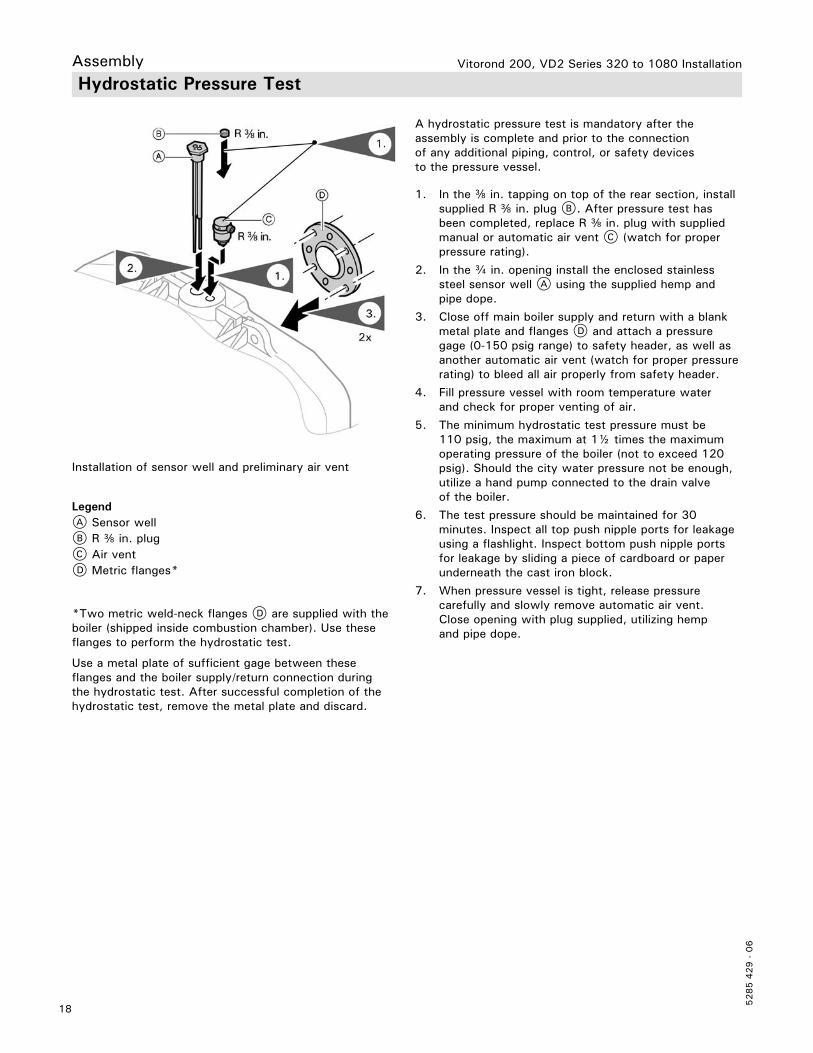
Assembly Hydrostatic Pressure Test
*Two metric weld-neck flanges D are supplied with the boiler (shipped inside combustion chamber). Use these flanges to perform the hydrostatic test.
Use a metal plate of sufficient gage between these flanges and the boiler supply/return connection during the hydrostatic test. After successful completion of the hydrostatic test, remove the metal plate and discard.
LegendA Sensor wellB R e in. plugC Air ventD Metric flanges*
1. In the e in. tapping on top of the rear section, install supplied R e in. plug B. After pressure test has been completed, replace R e in. plug with supplied manual or automatic air vent C (watch for proper pressure rating).
2. In the c in. opening install the enclosed stainless steel sensor well A using the supplied hemp and pipe dope.
3. Close off main boiler supply and return with a blank metal plate and flanges D and attach a pressure gage (0-150 psig range) to safety header, as well as another automatic air vent (watch for proper pressure rating) to bleed all air properly from safety header.
4. Fill pressure vessel with room temperature water and check for proper venting of air.
5. The minimum hydrostatic test pressure must be 110 psig, the maximum at 1½ times the maximum operating pressure of the boiler (not to exceed 120 psig). Should the city water pressure not be enough, utilize a hand pump connected to the drain valve of the boiler.
6. The test pressure should be maintained for 30 minutes. Inspect all top push nipple ports for leakage using a flashlight. Inspect bottom push nipple ports for leakage by sliding a piece of cardboard or paper underneath the cast iron block.
7. When pressure vessel is tight, release pressure carefully and slowly remove automatic air vent. Close opening with plug supplied, utilizing hemp and pipe dope.
A hydrostatic pressure test is mandatory after the assembly is complete and prior to the connection of any additional piping, control, or safety devices to the pressure vessel.
Installation of sensor well and preliminary air vent
19
5285 4
29 -
06
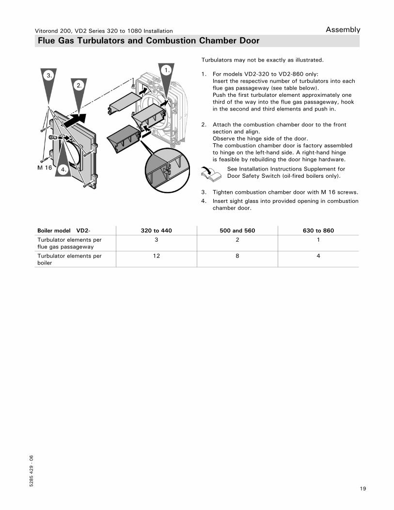
Vitorond 200, VD2 Series 320 to 1080 Installation Assembly Flue Gas Turbulators and Combustion Chamber Door
1. For models VD2-320 to VD2-860 only: Insert the respective number of turbulators into each flue gas passageway (see table below).
Push the first turbulator element approximately one third of the way into the flue gas passageway, hook in the second and third elements and push in.
2. Attach the combustion chamber door to the front section and align.
Observe the hinge side of the door. The combustion chamber door is factory assembled to hinge on the left-hand side. A right-hand hinge is feasible by rebuilding the door hinge hardware.
3. Tighten combustion chamber door with M 16 screws.
4. Insert sight glass into provided opening in combustion chamber door.
Boiler model VD2- 320 to 440 500 and 560 630 to 860
Turbulator elements per flue gas passageway
3 2 1
Turbulator elements per boiler
12 8 4
Turbulators may not be exactly as illustrated.
See Installation Instructions Supplement for Door Safety Switch (oil-fired boilers only).
Vitorond 200, VD2 Series 320 to 1080 Installation
5285 4
29 -
06
20
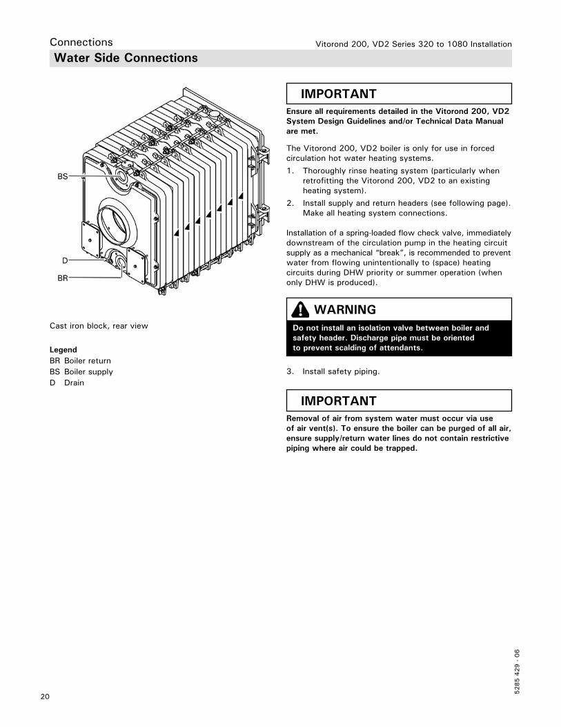
Connections Water Side Connections
Cast iron block, rear view
LegendBR Boiler returnBS Boiler supplyD Drain
The Vitorond 200, VD2 boiler is only for use in forced circulation hot water heating systems.
1. Thoroughly rinse heating system (particularly when retrofitting the Vitorond 200, VD2 to an existing heating system).
2. Install supply and return headers (see following page). Make all heating system connections.
Installation of a spring-loaded flow check valve, immediatelydownstream of the circulation pump in the heating circuit supply as a mechanical “break”, is recommended to preventwater from flowing unintentionally to (space) heating circuits during DHW priority or summer operation (when only DHW is produced).
WARNINGDo not install an isolation valve between boiler and safety header. Discharge pipe must be oriented to prevent scalding of attendants.
IMPORTANTRemoval of air from system water must occur via use of air vent(s). To ensure the boiler can be purged of all air, ensure supply/return water lines do not contain restrictive piping where air could be trapped.
IMPORTANTEnsure all requirements detailed in the Vitorond 200, VD2 System Design Guidelines and/or Technical Data Manual are met.
3. Install safety piping.
21
5285 4
29 -
06
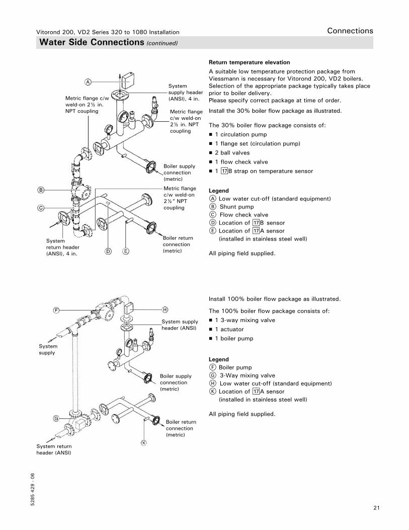
Vitorond 200, VD2 Series 320 to 1080 Installation Water Side Connections (continued)
A suitable low temperature protection package from Viessmann is necessary for Vitorond 200, VD2 boilers. Selection of the appropriate package typically takes place prior to boiler delivery.Please specify correct package at time of order.
Install the 30% boiler flow package as illustrated.
The 30% boiler flow package consists of:
H 1 circulation pump
H 1 flange set (circulation pump)
H 2 ball valves
H 1 flow check valve
H 1 aJB strap on temperature sensor
Metric flange c/w weld-on 2½ in. NPT coupling
Metric flangec/w weld-on 2½” NPT coupling
Metric flangec/w weld-on 2½ in. NPT coupling
Boiler return connection(metric)
Boiler supply connection(metric)
System return header (ANSI), 4 in.
System supply header (ANSI), 4 in.
Return temperature elevation
LegendA Low water cut-off (standard equipment)B Shunt pumpC Flow check valveD Location of aJB sensorE Location of aJA sensor
(installed in stainless steel well)
All piping field supplied.
Install 100% boiler flow package as illustrated.
The 100% boiler flow package consists of:
H 1 3-way mixing valve
H 1 actuator
H 1 boiler pump
Boiler return connection(metric)
Boiler supply connection(metric)
System supply header (ANSI)
System supply
System return header (ANSI)
LegendF Boiler pumpG 3-Way mixing valveH Low water cut-off (standard equipment)K Location of aJA sensor
(installed in stainless steel well)
All piping field supplied.
Connections
Vitorond 200, VD2 Series 320 to 1080 Installation
5285 4
29 -
06
22
CAUTIONThe Vitorond 200, VD2A boiler is not approved for side wall venting.
Connections Venting Connection
Chimney
For proper operation of the Vitorond 200, VD2 boiler, all products of combustion must be safely vented to the outdoors, while ensuring that flue gases do not cool prematurely.
It is critical that the chimney system be properly designed to handle the relatively cool flue gas temperatures produced by the Vitorond 200, VD2 boiler.
If the chimney system lacks sufficient insulation and/or the chimney diameter is too large, corrosive and damaging condensation will result due to flue gases cooling too quickly. If a calculated chimney diameter lies between two values, the larger diameter should be selected.
The chimney connection length between the boiler vent pipe collar and the chimney must be installed with insulation.
Vent pipe collar diameter does not automatically indicate vent/chimney size.
We recommend consulting a reputable chimney installer for advice in project-specific circumstances.
When installing the Vitorond 200, VD2 boiler, it is necessary to install a barometric draft regulator in the chimney/vent for proper operation of the boiler.
Install the barometric draft regulator within 5 to 7 ft. (1½ to 2 m) from the breeching outlet located at the rear of the boiler.
Never operate boiler without an installed venting system which safely vents all products of combustion to the outdoors. The vent system must comply with all applicable local and/or national codes.
Vitorond 200, VD2 boilers are Category I boilers as defined in ANSI Z21.13 when used with natural gas.Venting systems shall be sized and constructed in accordance with approved engineering methods (ASHRAE, HVAC Systems and Equipment Handbook, Chapter 31 “Chimney, Gas Vent, and Fireplace Systems”) including the chimney and boiler manufacturer’s instructions.
In Canada
For gas-fired boilers install venting system in accordance with all applicable local codes. In the absence of local codes, follow national codes CAN/CSA B149.1 or .2.For oil-fired boilers follow CSA B-139.
In U.S.A.
For gas-fired boilers connecting to gas vents or chimneys, vent installations shall be in accordance with Venting of Equipment of the National Fuel Gas Code, ANSI Z223.1 or applicable provisions of the local building codes.For oil-fired boilers follow NFPA 31. Always use latest editions of codes.
WARNINGWhen installing or insulating (overhead) piping or venting, do not stand on top panel of boiler. Advise other trades accordingly!
Venting Requirements
For natural gas or liquid propane use Type B vent or Type L vent for the entire vent whenever possible.
Venting option #1 (Category I venting)
The Vitorond 200, VD2 boiler is approved as a Category I appliance and must be vented accordingly.
23
5285 4
29 -
06
Venting Requirements (continued)
Connections
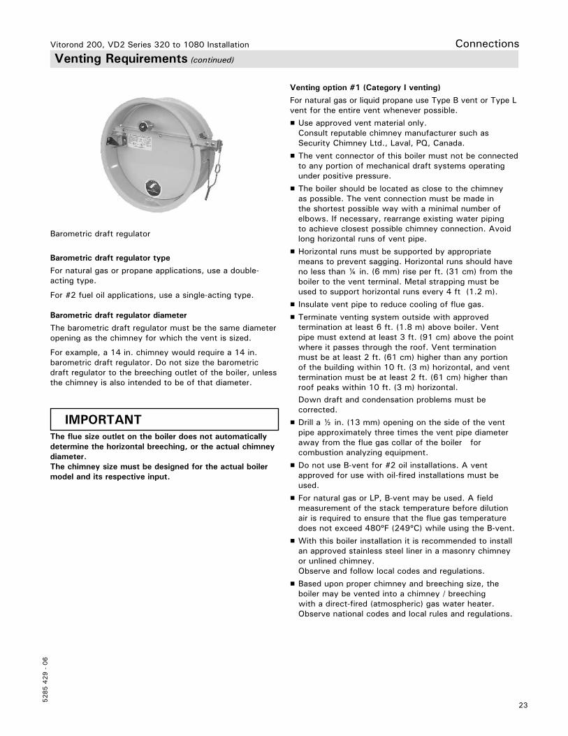
Barometric draft regulator type
For natural gas or propane applications, use a double-acting type.
For #2 fuel oil applications, use a single-acting type.
Barometric draft regulator diameter
The barometric draft regulator must be the same diameter opening as the chimney for which the vent is sized.
For example, a 14 in. chimney would require a 14 in. barometric draft regulator. Do not size the barometric draft regulator to the breeching outlet of the boiler, unless the chimney is also intended to be of that diameter.
Venting option #1 (Category I venting)
For natural gas or liquid propane use Type B vent or Type L vent for the entire vent whenever possible.
H Use approved vent material only. Consult reputable chimney manufacturer such as Security Chimney Ltd., Laval, PQ, Canada.
H The vent connector of this boiler must not be connected to any portion of mechanical draft systems operating under positive pressure.
H The boiler should be located as close to the chimney as possible. The vent connection must be made in the shortest possible way with a minimal number of elbows. If necessary, rearrange existing water piping to achieve closest possible chimney connection. Avoid long horizontal runs of vent pipe.
H Horizontal runs must be supported by appropriate means to prevent sagging. Horizontal runs should have no less than ¼ in. (6 mm) rise per ft. (31 cm) from the boiler to the vent terminal. Metal strapping must be used to support horizontal runs every 4 ft (1.2 m).
H Insulate vent pipe to reduce cooling of flue gas.
H Terminate venting system outside with approved termination at least 6 ft. (1.8 m) above boiler. Vent pipe must extend at least 3 ft. (91 cm) above the point where it passes through the roof. Vent termination must be at least 2 ft. (61 cm) higher than any portion of the building within 10 ft. (3 m) horizontal, and vent termination must be at least 2 ft. (61 cm) higher than roof peaks within 10 ft. (3 m) horizontal.
Down draft and condensation problems must be corrected.
H Drill a ½ in. (13 mm) opening on the side of the vent pipe approximately three times the vent pipe diameter away from the flue gas collar of the boiler for combustion analyzing equipment.
H Do not use B-vent for #2 oil installations. A vent approved for use with oil-fired installations must be used.
H For natural gas or LP, B-vent may be used. A field measurement of the stack temperature before dilution air is required to ensure that the flue gas temperature does not exceed 480ºF (249ºC) while using the B-vent.
H With this boiler installation it is recommended to install an approved stainless steel liner in a masonry chimney or unlined chimney.
Observe and follow local codes and regulations.
H Based upon proper chimney and breeching size, the boiler may be vented into a chimney / breeching with a direct-fired (atmospheric) gas water heater. Observe national codes and local rules and regulations.
IMPORTANTThe flue size outlet on the boiler does not automatically determine the horizontal breeching, or the actual chimney diameter.The chimney size must be designed for the actual boiler model and its respective input.
Barometric draft regulator
Vitorond 200, VD2 Series 320 to 1080 Installation
Vitorond 200, VD2 Series 320 to 1080 Installation
5285 4
29 -
06
24
Connections Venting Requirements (continued)
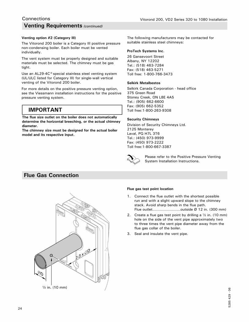
1. Connect the flue outlet with the shortest possible run and with a slight upward slope to the chimney stack. Avoid sharp bends in the flue path. Flue outlet.......................outside Ø 12 in. (300 mm)
2. Create a flue gas test point by drilling a b in. (10 mm) hole on the side of the vent pipe approximately two to three times the vent pipe diameter away from the flue gas collar of the boiler.
3. Seal and insulate the vent pipe.
Venting option #2 (Category III)
The Vitorond 200 boiler is a Category III positive pressure non-condensing boiler. Each boiler must be vented individually.
The vent system must be properly designed and suitable materials must be selected. The chimney must be gas tight.
Use an AL29-4C® special stainless steel venting system (UL/ULC listed for Category III) for single-wall vertical venting of the Vitorond 200 boiler.
For more details on the positive pressure venting option, see the Viessmann installation instructions for the positivepressure venting system.
The following manufacturers may be contacted for suitable stainless steel chimneys:
ProTech Systems Inc.
26 Gansevoort StreetAlbany, NY 12202Tel.: (518) 463-7284Fax: (518) 463-5271Toll free: 1-800-766-3473
Selkirk Metalbestos
Selkirk Canada Corporation - head office375 Green RoadStoney Creek, ON L8E 4A5Tel.: (905) 662-6600Fax: (905) 662-5352Toll free:1-800-263-9308
Security Chimneys
Division of Security Chimneys Ltd.2125 MontereyLaval, PQ H7L 3T6Tel.: (450) 973-9999Fax: (450) 973-2222Toll free:1-800-667-3387
Please refer to the Positive Pressure Venting System Installation Instructions.
IMPORTANTThe flue size outlet on the boiler does not automatically determine the horizontal breeching, or the actual chimney diameter.The chimney size must be designed for the actual boiler model and its respective input.
Flue Gas Connection
Flue gas test point location
25
5285 4
29 -
06
Vitorond 200, VD2 Series 320 to 1080 Installation Connections Removal of Existing Boiler
1. Seal any unused openings in the common venting system.
2. Visually inspect the venting system for proper size and horizontal pitch and determine there is no blockage or restriction, leakage, corrosion, or any other deficiency which could cause an unsafe condition.
3. To determine whether the building is operating under negative pressure, insofar as is practical, close all building doors and windows and all doors between the space in which the appliances remaining connected to the common venting system are located and other spaces of the building. Turn on any exhaust fans, such as range hoods and bathroom exhausts, so they will operate at maximum speed. (Do not operate a summer exhaust fan). Close fireplace dampers.
4. Place in operation the appliance being inspected. Follow the lighting instructions. Adjust thermostat so appliance will operate continuously.
5. Test for spillage at the barometric draft control relief opening 5 minutes of high fire/full load burner operation. Use the flame of a match or a candle, or an approved test.
6. After it has been determined that each appliance remaining connected to the common venting system properly vents when tested as outlined above, return doors, windows, exhaust fans, fireplace dampers and any other gas burning appliance to their previous condition of use.
7. Any improper operation of the common venting system should be corrected so the installation conforms with the National Fuel Gas Code, ANSI Z223.1-1992 or latest edition. When resizing, any portion of the common venting system should be resized to approach the minimum size as determined using the appropriate tables in Appendix G in the National Fuel Gas Code, ANSI Z223.1.
When an existing boiler is removed from a common venting system, the common venting system is likely to be too large for proper venting of the appliances remaining connected to it.
At the time of removal of an existing boiler, the following steps shall be followed with each appliance remaining connected to the common venting system placed in operation, while the other appliances remaining connected to the venting system are not in operation.
Vitorond 200, VD2 Series 320 to 1080 Installation
5285 4
29 -
06
26
Connections Safety Connections and Pressure Testing
Pressure relief valve
Do not install any valve(s) between the pressure relief valve and the boiler. When installing a discharge pipe from relief valve to drain, adhere to the following excerpt from the ASME Boiler and Pressure Vessel Code:
1. When a discharge pipe is used, its internal cross-sectional area shall be not less than the full area of the valve outlet or of the total of the valve outlets discharging thereinto and shall be as short and straight as possible and so arranged as to avoid undue stress on the valve or valves. When an elbow is placed on a safety or safety relief valve discharge pipe, it shall be located close to the valve outlet.
The boiler must be leak tested and hydrostatically pressure tested with a maximum of 120 psig (827 kPa) and a minimum of 110 psig (689 kPa) before being connected to piping or an electrical power supply and placed in operation.
1. Install supply and return headers complete with pressure gage, temperature gage, air vent, low water cut-off, boiler drain valve and bypass pump. Pipe up to isolation valves. Close isolation valves.
2. Install temporary caps on the nipples for mounting the pressure relief valve and expansion tank.
3. Connect hose to boiler drain valve and fill boiler slowly until pressure gage indicates max. 120 psig (827 kPa).
Boiler Pressure Test
Low Water Cut-off (LWCO)
If boiler is installed above radiation level, a low water cut-off device of approved type (standard equipment) must be installed in all instances. The approved low water cut-off device must be installed by the mechanical contractor where required by local codes.
Viessmann recommends the use of a LWCO in all instances.
4. Maintain pressure for 30 minutes. During time of pressure testing, do not leave boiler unattended.
5. Inspect all push nipples and pipe connections with flashlight for leaks. Place a piece of paper under the cast iron block to catch any minor leaks from the bottom push nipples.
6. After 30 minutes, release water pressure from boiler by opening drain valve slowly, remove caps and install pressure relief valve and expansion tank immediately.
After boiler has passed pressure test, proceed with installation.
2. The discharge from safety or safety relief valves shall be so arranged that there will be no danger of scalding attendants. When the safety or safety relief valve discharge is piped away from the boiler to the point of discharge, there shall be provisions made for properly draining the pipe. The size and arrangement of the discharge pipe shall be such that any pressure that may exist or develop will not reduce the relieving capacity of the relieving devices that are required to protect the boiler.
27
5285 4
29 -
06
Vitorond 200, VD2 Series 320 to 1080 Installation Enclosure Enclosure Installation
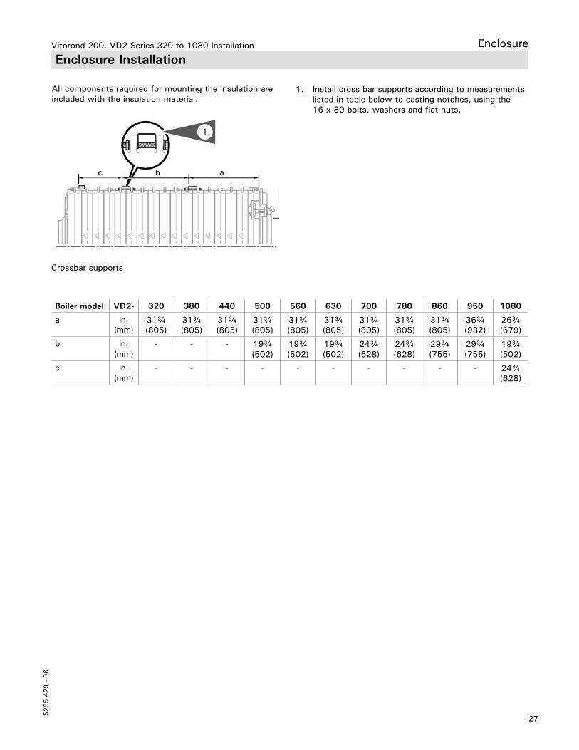
1. Install cross bar supports according to measurements listed in table below to casting notches, using the 16 x 80 bolts, washers and flat nuts.
Crossbar supports
Boiler model VD2- 320 380 440 500 560 630 700 780 860 950 1080
a in. (mm)
31c(805)
31c(805)
31c(805)
31c(805)
31c(805)
31c(805)
31c(805)
31c(805)
31c(805)
36c(932)
26c(679)
b in. (mm)
- - - 19c(502)
19c(502)
19c(502)
24c(628)
24c(628)
29c(755)
29c(755)
19c(502)
c in. (mm)
- - - - - - - - - - 24c(628)
All components required for mounting the insulation are included with the insulation material.
Boiler front
Vitorond 200, VD2 Series 320 to 1080 Installation
5285 4
29 -
06
28
Enclosure Installation (continued)
Enclosure
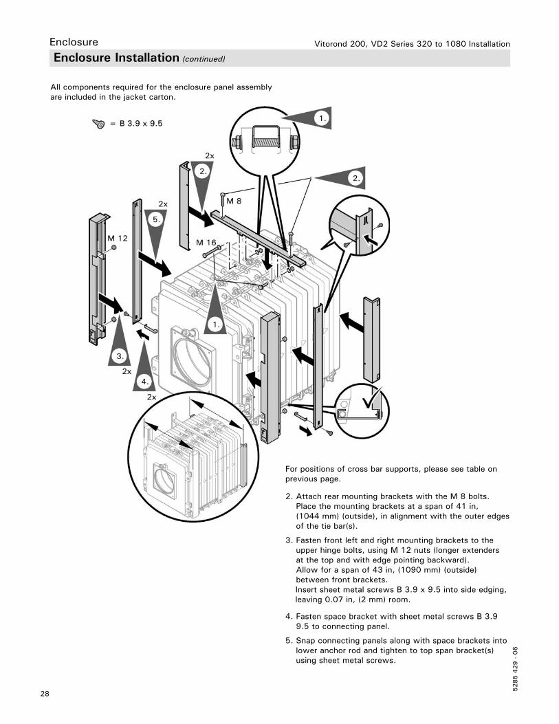
4. Fasten space bracket with sheet metal screws B 3.9 9.5 to connecting panel.
5. Snap connecting panels along with space brackets into lower anchor rod and tighten to top span bracket(s) using sheet metal screws.
All components required for the enclosure panel assembly are included in the jacket carton.
For positions of cross bar supports, please see table on previous page.
2. Attach rear mounting brackets with the M 8 bolts. Place the mounting brackets at a span of 41 in, (1044 mm) (outside), in alignment with the outer edges of the tie bar(s).
3. Fasten front left and right mounting brackets to the upper hinge bolts, using M 12 nuts (longer extenders at the top and with edge pointing backward). Allow for a span of 43 in, (1090 mm) (outside) between front brackets.
Insert sheet metal screws B 3.9 x 9.5 into side edging, leaving 0.07 in, (2 mm) room.
29
5285 4
29 -
06
EnclosureVitorond 200, VD2 Series 320 to 1080 Installation Enclosure Installation (continued)
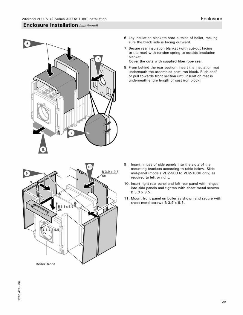
6. Lay insulation blankets onto outside of boiler, making sure the black side is facing outward.
7. Secure rear insulation blanket (with cut-out facing to the rear) with tension spring to outside insulation blanket.
Cover the cuts with supplied fiber rope seal.
8. From behind the rear section, insert the insulation mat underneath the assembled cast iron block. Push and/or pull towards front section until insulation mat is underneath entire length of cast iron block.
Boiler front
9. Insert hinges of side panels into the slots of the mounting brackets according to table below. Slide mid-panel (models VD2-500 to VD2-1080 only) as required to left or right.
10. Insert right rear panel and left rear panel with hinges into side panels and tighten with sheet metal screws B 3.9 x 9.5.
11. Mount front panel on boiler as shown and secure with sheet metal screws B 3.9 x 9.5.
Vitorond 200, VD2 Series 320 to 1080 Installation
5285 4
29 -
06
30
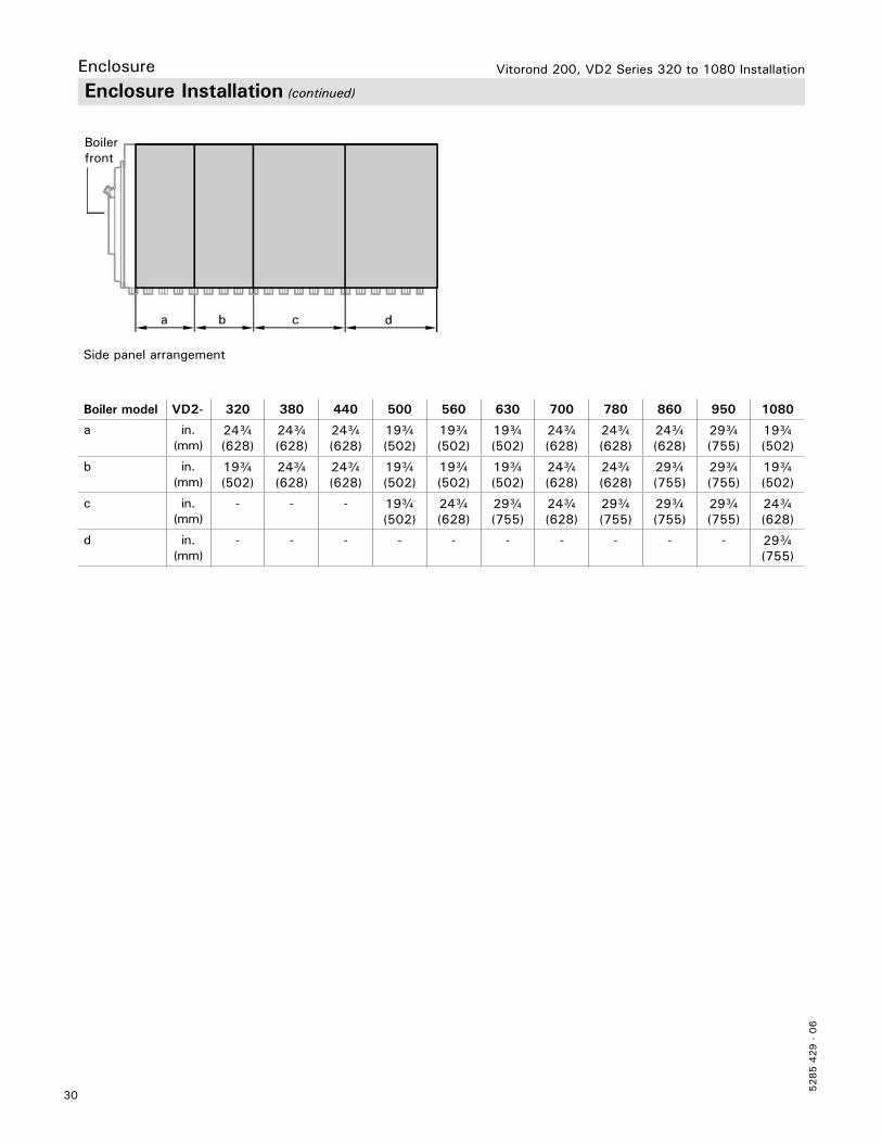
Enclosure Enclosure Installation (continued)
Boiler model VD2- 320 380 440 500 560 630 700 780 860 950 1080
a in. (mm)
24c (628)
24c (628)
24c (628)
19c (502)
19c (502)
19c (502)
24c (628)
24c (628)
24c (628)
29c (755)
19c (502)
b in. (mm)
19c (502)
24c (628)
24c (628)
19c (502)
19c (502)
19c (502)
24c (628)
24c (628)
29c (755)
29c (755)
19c (502)
c in. (mm)
- - - 19c (502)
24c (628)
29c (755)
24c (628)
29c (755)
29c (755)
29c (755)
24c (628)
d in. (mm)
- - - - - - - - - - 29c (755)
Boiler front
Side panel arrangement
31
5285 4
29 -
06
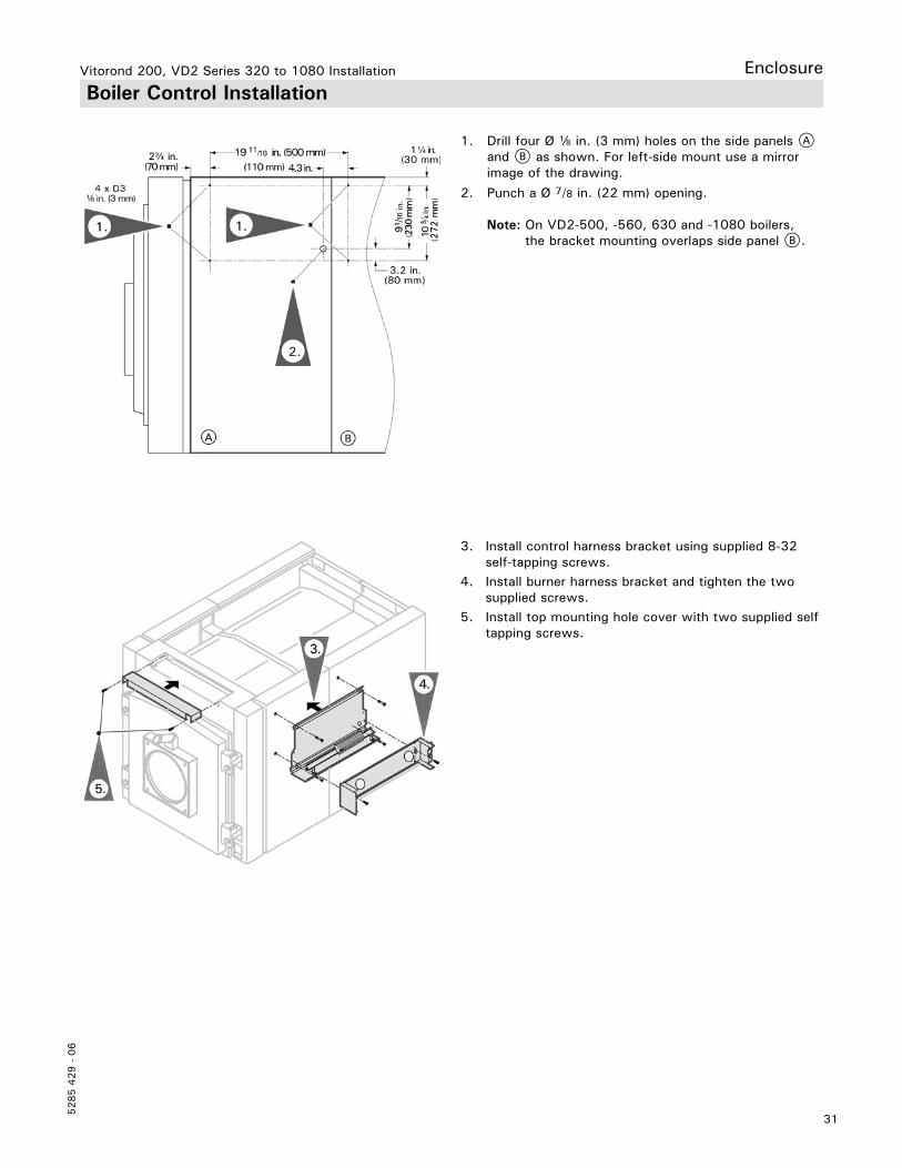
Vitorond 200, VD2 Series 320 to 1080 Installation Enclosure Boiler Control Installation
3. Install control harness bracket using supplied 8-32 self-tapping screws.4. Install burner harness bracket and tighten the two supplied screws.5. Install top mounting hole cover with two supplied self tapping screws.
1. Drill four Ø d in. (3 mm) holes on the side panels A and B as shown. For left-side mount use a mirror image of the drawing.
2. Punch a Ø 7/8 in. (22 mm) opening.
Note: On VD2-500, -560, 630 and -1080 boilers, the bracket mounting overlaps side panel B.
Vitorond 200, VD2 Series 320 to 1080 Installation
5285 4
29 -
06
32
Enclosure Boiler Control Installation (continued)
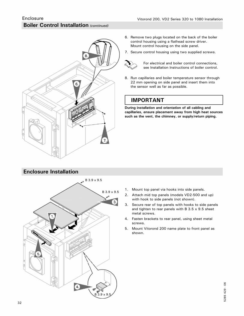
6. Remove two plugs located on the back of the boiler control housing using a flathead screw driver. Mount control housing on the side panel.
7. Secure control housing using two supplied screws.
8. Run capillaries and boiler temperature sensor through 22 mm opening on side panel and insert them into the sensor well as far as possible.
IMPORTANTDuring installation and orientation of all cabling and capillaries, ensure placement away from high heat sources such as the vent, the chimney, or supply/return piping.
For electrical and boiler control connections, see Installation Instructions of boiler control.
1. Mount top panel via hooks into side panels.
2. Attach mid top panels (models VD2-500 and up) with hook to side panels (not shown).
3. Secure rear of top panels with hooks to side panels and tighten to rear panels with B 3.5 x 9.5 sheet metal screws.
4. Fasten brackets to rear panel, using sheet metal screws.
5. Mount Vitorond 200 name plate to front panel as shown.
Enclosure Installation
B 3.9 x 9.5
B 3.9 x 9.5
B 3.9 x 9.5
33
5285 4
29 -
06
Vitorond 200, VD2 Series 320 to 1080 Installation Burner Burner Installation
IMPORTANTThe boiler and burner shall be installed such that all componentry is protected from water (dripping, spraying, rain, etc.) during boiler operation and service.
IMPORTANTThe sight glass must be sealed for pressure tightness.
IMPORTANTDo not overtighten the brass sight glass holder. If overtightened, there is a risk of breaking the sight glass.
IMPORTANTBurner must be ordered specifically for a particular fuel, or as a combination burner specifying the fuels. Please see separate burner selection chart for Vitorond 200, VD2 boiler series in the Technical Data Manual.
Viessmann has made Weishaupt and Riello burners standard on all Vitorond 200, VD2 boilers; for details seeTechnical Data Manual and/or Weishaupt burner manuals (supplied with burner).
Only oil- or gas-fired burners of the approved type can be utilized with the Vitorond 200, VD2 boiler. The boiler must be fired with positive pressure in the combustion chamber.
Combustion chamber sight glass
All Vitorond 200 combustion chamber doors are equipped with a sight glass to observe the burner flame. In order to avoid fogging of the glass, the observation port is ventilated.
Connect the sight glass to the burner with the clear, plastic hose supplied.
Fuels
Oil - Fuel Oil #2Gas - Natural gas or LP
For burner details, see Technical Data Manual and/or burner manufacturer’s relevant literature.
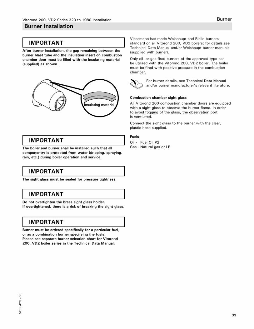
IMPORTANTAfter burner installation, the gap remaining between the burner blast tube and the insulation insert on combustion chamber door must be filled with the insulating material (supplied) as shown.
Insulating material
Vitorond 200, VD2 Series 320 to 1080 Installation
5285 4
29 -
06
34
Burner
Fully modulating burner
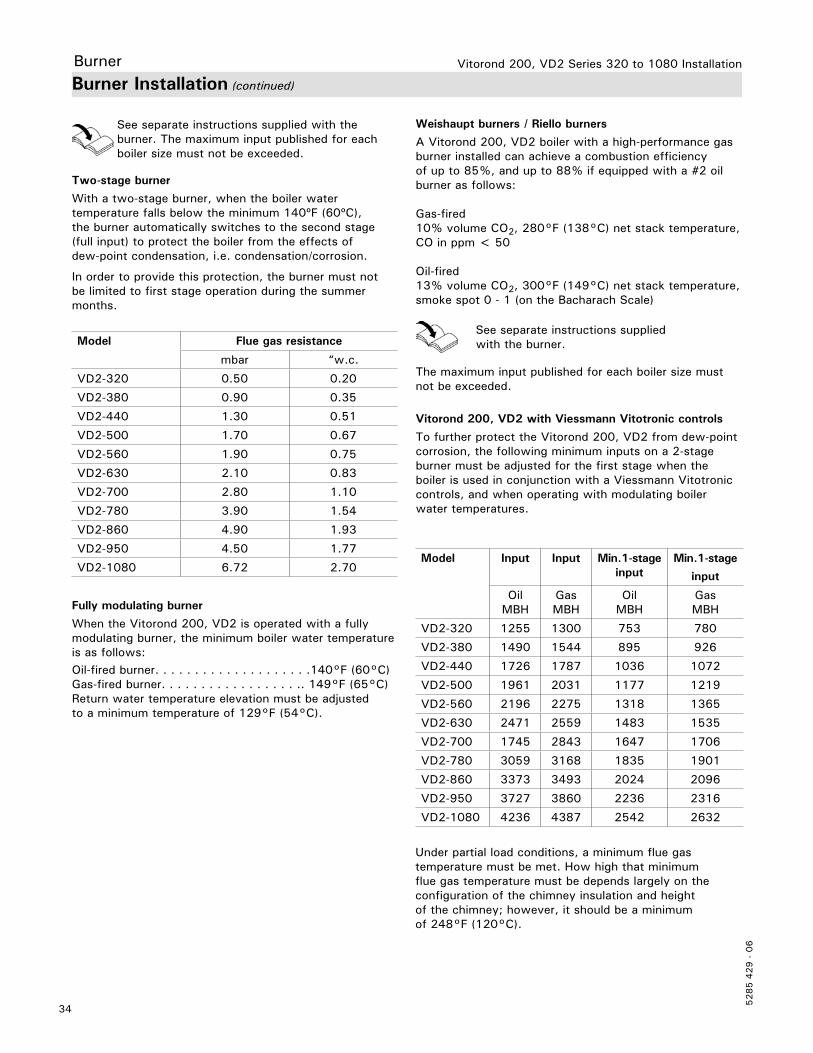
When the Vitorond 200, VD2 is operated with a fully modulating burner, the minimum boiler water temperature is as follows:Oil-fired burner. . . . . . . . . . . . . . . . . . . .140°F (60°C)Gas-fired burner. . . . . . . . . . . . . . . . . .. 149°F (65°C)Return water temperature elevation must be adjusted to a minimum temperature of 129°F (54°C).
Model Flue gas resistance
mbar “w.c.
VD2-320 0.50 0.20
VD2-380 0.90 0.35
VD2-440 1.30 0.51
VD2-500 1.70 0.67
VD2-560 1.90 0.75
VD2-630 2.10 0.83
VD2-700 2.80 1.10
VD2-780 3.90 1.54
VD2-860 4.90 1.93
VD2-950 4.50 1.77
VD2-1080 6.72 2.70Model Input Input Min.1-stage
inputMin.1-stage
input
OilMBH
GasMBH
OilMBH
GasMBH
VD2-320 1255 1300 753 780
VD2-380 1490 1544 895 926
VD2-440 1726 1787 1036 1072
VD2-500 1961 2031 1177 1219
VD2-560 2196 2275 1318 1365
VD2-630 2471 2559 1483 1535
VD2-700 1745 2843 1647 1706
VD2-780 3059 3168 1835 1901
VD2-860 3373 3493 2024 2096
VD2-950 3727 3860 2236 2316
VD2-1080 4236 4387 2542 2632
Weishaupt burners / Riello burners
A Vitorond 200, VD2 boiler with a high-performance gas burner installed can achieve a combustion efficiency of up to 85%, and up to 88% if equipped with a #2 oil burner as follows:
Gas-fired10% volume CO2, 280°F (138°C) net stack temperature, CO in ppm < 50
Oil-fired13% volume CO2, 300°F (149°C) net stack temperature, smoke spot 0 - 1 (on the Bacharach Scale)
The maximum input published for each boiler size must not be exceeded.
Vitorond 200, VD2 with Viessmann Vitotronic controls
To further protect the Vitorond 200, VD2 from dew-point corrosion, the following minimum inputs on a 2-stage burner must be adjusted for the first stage when the boiler is used in conjunction with a Viessmann Vitotronic controls, and when operating with modulating boiler water temperatures.
See separate instructions supplied with the burner.
Under partial load conditions, a minimum flue gas temperature must be met. How high that minimum flue gas temperature must be depends largely on the configuration of the chimney insulation and height of the chimney; however, it should be a minimum of 248°F (120°C).
Two-stage burner
With a two-stage burner, when the boiler water temperature falls below the minimum 140ºF (60ºC), the burner automatically switches to the second stage (full input) to protect the boiler from the effects of dew-point condensation, i.e. condensation/corrosion.
In order to provide this protection, the burner must not be limited to first stage operation during the summer months.
Burner Installation (continued)
See separate instructions supplied with the burner. The maximum input published for each boiler size must not be exceeded.
35
5285 4
29 -
06
Vitorond 200, VD2 Series 320 to 1080 Installation System Preparation
Start-up
Combustion air supply
Provisions for combustion and ventilation air must be madein accordance with applicable local codes.In the absence of local codes, use CAN/CSA-B149.1 or .2 Installation Codes for Gas Burning Appliances for Canada. For U.S. installations use section 5.3, Air for Combustion and Ventilation, of the National Fuel Gas Code ANSI Z223.1.
For oil burning installations use CSA B-139 for oil installations in Canada and NFPA 31 Standard for the Installation of Oil Burning Equipment in the US.Always use latest editions of codes.
Whenever possible, install boiler near an outside wall so that it is easy to duct fresh air directly to the boiler area. Refer to national codes for duct sizing and allowable lengths. Round ducts can be used.
The boiler location must never be under negative pressure. Exhaust fans, attic fans, or dryer fans may cause air to be exhausted at a rate higher than air can enter the structure for safe combustion.
WARNINGFailure to provide an adequate supply of fresh combustion air can cause poisonous flue gases to enter living space which can cause severe personal injury or loss of life.
WARNINGNever cover the boiler or store debris or other materials near the boiler, or in any way block the flow of adequate fresh air to the boiler. Never cover the combustion air opening or put anything inside the draft hood. Advise system operator/ultimate owner accordingly.
WARNINGThe boiler must not be located in areas or rooms where chemicals are stored, or aggressive vapors from (i.e. bleach, hair spray, methyl chloride, carbon tetrachloride or perchloroethylene) or high dust levels or humidity levels are present. Heat exchanger corrosion might occur and reduce the lifetime of the boiler significantly. If above criteria are not properly observed and boiler damage results, any warranty on the complete boiler and related components will be null and void.
Gas piping pressure test
A sediment trap/dirt pocket must be provided upstream of all gas controls. Provisions for connecting vent lines or vent limiters are on gas regulator.
The boiler and its individual shut-off valve must be disconnected from the gas supply piping system during any pressure testing of that system at test pressures in excess of 14” w.c. (3.5 kPa).
The boiler must be isolated from the gas supply piping system by closing its individual manual shut-off valve during any pressure testing of the gas supply piping system at test pressures equal to or less than 14” w.c. (3.5 kPa).
Unions and the gas manifold have not been factory-tested. A leak test must be completed during initial trial operation of burner by a licensed gas fitter.
1. Connect and size gas supply piping in accordance with local and national codes.
2. Perform leak test. Never check for gas leaks with an open flame. Use approved liquid spray solution for bubble test. Ensure that no liquid is sprayed on any electrical components, wires or connectors. Do not allow leak detection fluid to contact gas valve regulator or regulator vent opening.
3. Remove air from gas line with an approved gas purge burner or vent to outdoors.
IMPORTANT½ psig = 14 “w.c.
Vitorond 200, VD2 Series 320 to 1080 Installation
5285 4
29 -
06
36
Start-up
j Open valve(s) in oil or gas fuel supply lines. j Activate all switches for heating system - system switch, heating system pump, burner power supply, etc. (observe instructions given by burner manufacturer).j If cold-starting burner (or if restarting burner after lengthy service procedures), close off heating system supply to ensure the boiler passes through the dew-point rapidly.j Once the supply water temperature has risen above the minimum, gradually open up the boiler supply and return valves to the heating system, and switch the burner to automatic.j Check all gaskets and connections and retighten if necessary.j Check and retighten bolts of combustion chamber door and clean-out opening covers several days after start-up.
Follow instructions of boiler control, oil and/ or gas power burner during boiler start-up.
Prior to Start-up
WARNINGEnsure the water quality was tested and is in compliance with the guidelines for system-fill water. Failure to do so may result in improper operation and/or damage to the heating system.
j Ensure that all turbulators are completely inserted into the flue gas passageways (open combustion chamber door).j Ensure that combustion air openings and ventilation air openings in mechanical room are open.j Ensure the heating system has been filled with water and is completely purged of air.
j Check cold fill pressure of heating system.j Check oil supply or proper natural or propane gas supply pressure.j Ensure proper barometric draft regulator is installed (field supplied).j Ensure clean out openings near flue gas collar are closed tightly.
Ensure that spring-loaded flow check valves are manually opened prior to filling the heating system with water.
Once the system is completely filled and purged of air, ensure that spring-loaded flow check valves are again closed (set into “flow-check” operation).
Water treatment should be considered in areas where it is known that boiler feed water contains a high mineral content and hardness.
In areas where freezing might occur, an antifreeze may be added to the system water to protect the system. Please adhere to the specifications given by the antifreeze manufacturer. Do not use automotive silicate-based antifreeze.
Initial System Fill
Please observe that an antifreeze/water mixture may require a backflow preventer within the automatic water feed and influence components such as diaphragm expansion tanks, radiation, etc.
A 40% antifreeze content will provide freeze-up protection to -10°F (-23°C). Do not use antifreeze other than specifically made for hot water heating systems.
The system also may contain components which might be negatively affected by antifreeze. Check total system frequently when filled with antifreeze.
37
5285 4
29 -
06
Vitorond 200, VD2 Series 320 to 1080 Installation Start-up Start-up Information
Start-up after extended shut-down
If the system was shut down for an extended period of time, restart and recondition the system.
H Ensure all national and/or local rules and regulations have been adhered to in this installation. Do not attempt to start the boiler if you smell gas. If you smell gas, open windows. Do not touch electrical switches, extinguish any open flame, close all gas valves immediately. Call your gas supplier immediately from a neighbor’s phone.
H For oil burners, do not reset the burner flame safeguard control more than two times.
H Check system for proper water fill (cold fill pressure). Ensure that complete system is properly vented. Adjust automatic feed valve to proper desired fill pressure. Do not tamper with the unit or controls. Never burn garbage or paper in the unit or leave combustible materials around it.
WARNINGIf system is subject to freezing temperatures and is not filled with antifreeze for protection, the system including the boiler must be drained of water. The valve before the automatic feed valve (if installed) must be closed; any other valves, air vents and drain valves must stay open.
Depending on the control system utilized, reprogramming of the control system might be necessary in the event of lengthy power interruption.
Initial start-up
Initial start-up must be performed by qualified personnel; values and calibrations specified in the Technical Data section on page 36 in this manual are to be recorded at this time.
Instructing the system user
The installer of the system is responsible to ensure the system operator/ultimate owner is made familiar with the functioning of the system, its activation, and its shut-down. The following topics must be covered:
H Proper system operation sequence.
H Explain the equipment as well as the need for combustion air.
H Demonstrate an emergency shut-down, what to do and what not.
H Explain that there is no substitute for proper maintenance to help ensure safe operation.
H Annual inspection is recommended.
Shut-down
Deactivate main power to heating boiler(s) and burner(s) if burners have separate power supply, and deactivate power to circulating pump(s). Close all boiler isolation valve(s) as well as all fuel supply valve(s).
Extended shut-down periods
If after the heating period the boiler is shut down for the summer months (no domestic hot water production), the boiler should be properly cleaned, incl. combustion chamber, flue gas passageways, and, as necessary,vent pipe connector, to avoid corrosion.
The boiler and system must remain filled with water. Do not drain boiler or heating system.
Vitorond 200, VD2 Series 320 to 1080 Installation
5285 4
29 -
06
38
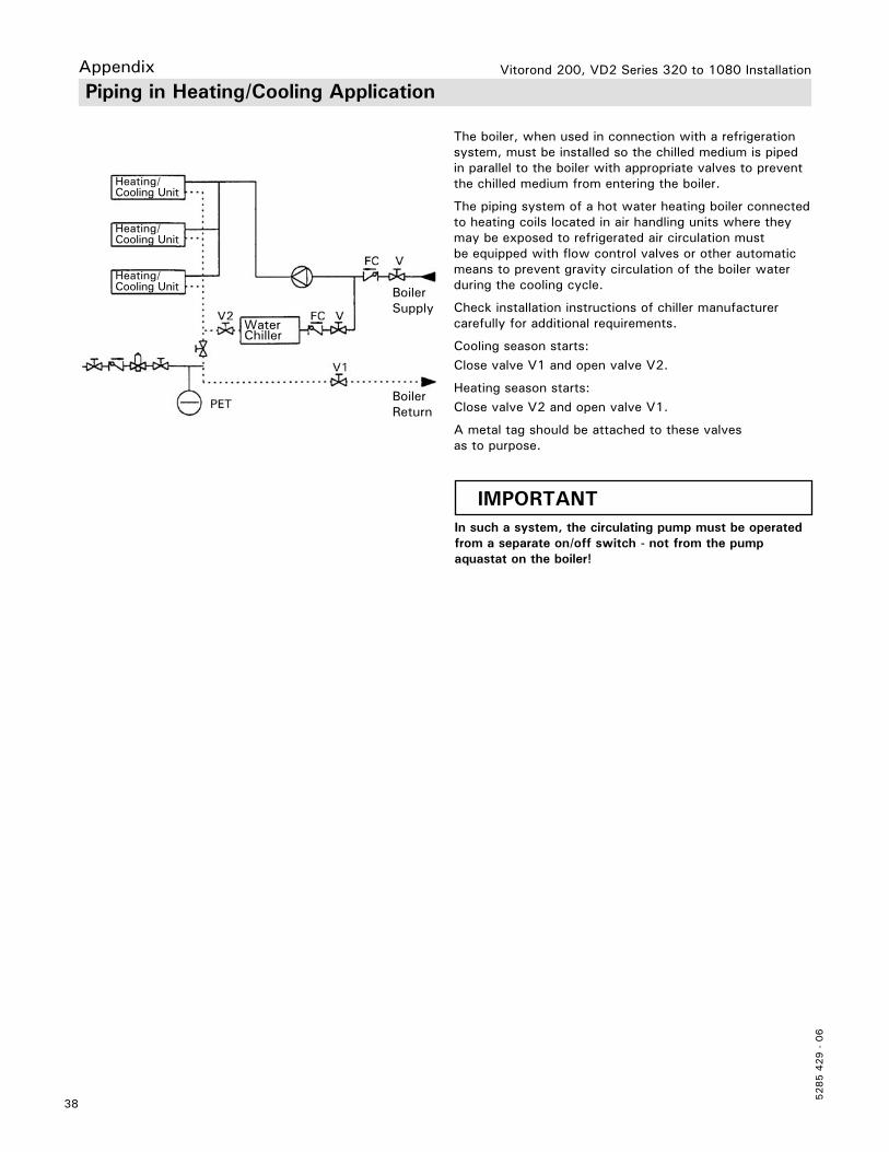
Appendix Piping in Heating/Cooling Application
The boiler, when used in connection with a refrigeration system, must be installed so the chilled medium is piped in parallel to the boiler with appropriate valves to prevent the chilled medium from entering the boiler.
The piping system of a hot water heating boiler connected to heating coils located in air handling units where they may be exposed to refrigerated air circulation must be equipped with flow control valves or other automatic means to prevent gravity circulation of the boiler water during the cooling cycle.
Check installation instructions of chiller manufacturer carefully for additional requirements.
Cooling season starts:Close valve V1 and open valve V2.
Heating season starts:Close valve V2 and open valve V1.
A metal tag should be attached to these valves as to purpose.
Heating/Cooling Unit
Heating/Cooling Unit
Heating/Cooling Unit
WaterChiller
BoilerReturn
BoilerSupply
IMPORTANTIn such a system, the circulating pump must be operated from a separate on/off switch - not from the pump aquastat on the boiler!
39
5285 4
29 -
06
Vitorond 200, VD2 Series 320 to 1080 Installation AppendixTechnical Data
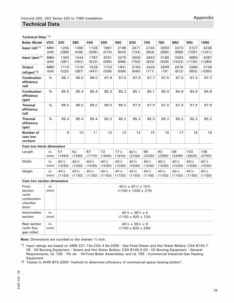
Technical Data *1
Boiler Model VD2- 320 380 440 500 560 630 700 780 860 950 1080
Input (oil)*1 MBH (kW)
1255(368)
1490(436)
1726(506)
1961(574)
2196(643)
2471(724)
2745 (804)
3059(896)
3373(988)
3727 (1091
4236(1241)
Input (gas)*1 MBH (kW)
1300(381)
1544(452)
1787(523)
2031(595)
2275(666)
2559(750)
2843 (833)
3168(928)
3493(1023)
3860 (1130)
4387(1285)
Output
(oil/gas)*2MBH (kW)
1110(325)
1319(387)
1526(447)
1732(508)
1941(569)
2183(640)
2425 (711)
2699(791
2976(872)
3288 (963)
3738(1095)
Combustion efficiency (oil)
% 88.1 88.0 88.0 87.9 87.8 87.8 87.7 87.6 87.5 87.4 87.3
Combustion efficiency (gas)
% 85.5 85.4 85.4 85.3 85.2 85.1 85.1 85.0 84.9 84.8 84.6
Thermal efficiency (oil)
% 88.0 88.0 88.0 88.0 88.0 87.9 87.9 87.9 87.9 87.8 87.8
Thermal efficiency (gas)
% 85.4 85.4 85.4 85.3 85.3 85.3 85.3 85.2 85.2 85.2 85.2
Number ofcast iron sections
9 10 11 12 13 14 15 16 17 18 19
Cast iron block dimensions
Length in. (mm)
57(1450)
62(1580)
67(1710)
72(1840)
77b(1970)
82b(2100)
88(2230)
93(2360)
98(2490)
103 (2620)
108(2750)
Width in. (mm)
40b(1030)
40b(1030)
40b(1030)
40b(1030)
40b(1030)
40b(1030)
40b(1030)
40b(1030)
40b(1030)
40b(1030)
40b(1030)
Height in. (mm)
45a(1150)
45a(1150)
45a(1150)
45a(1150)
45a(1150)
45a(1150)
45a(1150)
45a(1150)
45a(1150)
45a(1150)
45a(1150)
Cast iron section dimensions
Frontsection (with combustionchamberdoor)
in. (mm)
45a x 40b x 10c(1150 x 1030 x 270)
Intermediate section
in. (mm)
45a x 36a x 5(1150 x 920 x 125)
Rear section(with fluegas collar)
in. (mm)
45a x 36a x 9(1150 x 920 x 290)
*1 Input ratings are based on ANSI Z21.13a.CSA 4.9a-2005 - Gas Fired Steam and Hot Water Boilers; CSA B140.7-05 - Oil Burning Equipment - Steam and Hot Water Boilers; CSA B140.0-03 - Oil Burning Equipment - General Requirements; UL 726 - 7th ed. - Oil-Fired Boiler Assemblies; and UL 795 - Commercial Industrial Gas Heating Equipment.
*2 Tested to AHRI BTS-2000 “method to determine efficiency of commercial space heating boilers”.
Note: Dimensions are rounded to the nearest a inch.
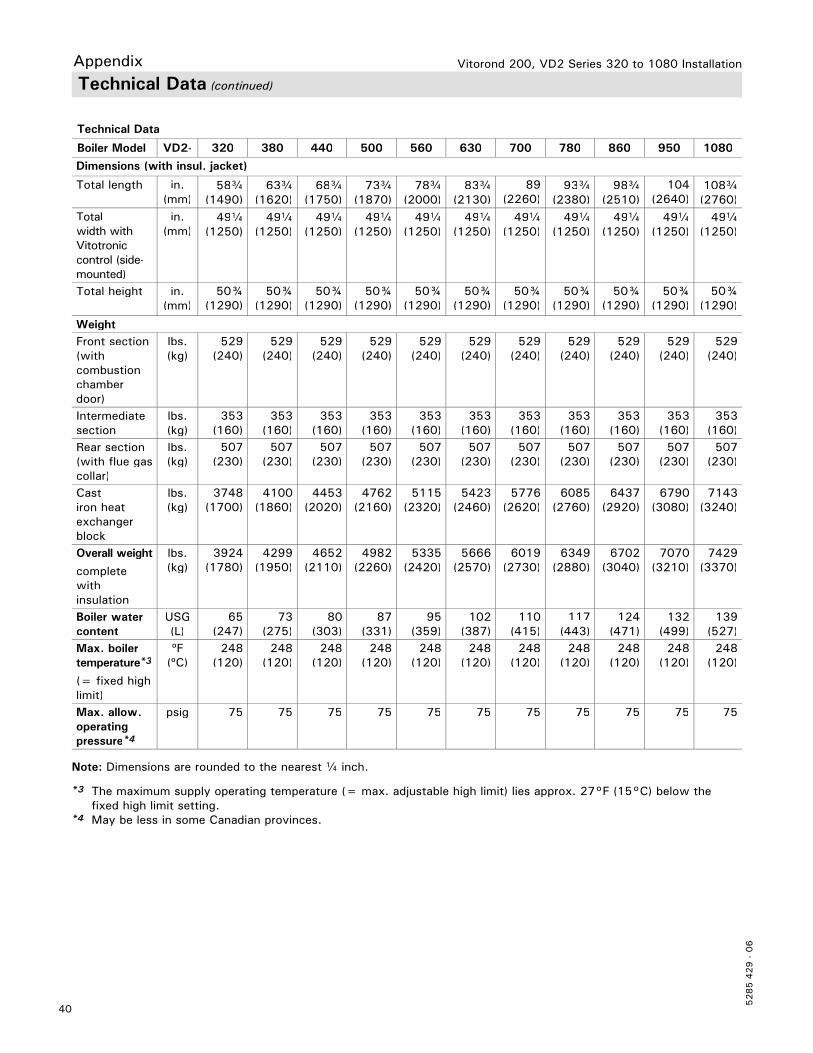
Vitorond 200, VD2 Series 320 to 1080 Installation
5285 4
29 -
06
40
Technical Data (continued)
Appendix
Technical Data
Boiler Model VD2- 320 380 440 500 560 630 700 780 860 950 1080
Dimensions (with insul. jacket)
Total length in. (mm)
58c(1490)
63c(1620)
68c(1750)
73c(1870)
78c(2000)
83c(2130)
89(2260)
93c(2380)
98c(2510)
104(2640)
108c(2760)
Totalwidth withVitotronic control (side-mounted)
in. (mm)
49a(1250)
49a(1250)
49a(1250)
49a(1250)
49a(1250)
49a(1250)
49a(1250)
49a(1250)
49a(1250)
49a(1250)
49a(1250)
Total height in. (mm)
50¾(1290)
50¾(1290)
50¾(1290)
50¾(1290)
50¾(1290)
50¾(1290)
50¾(1290)
50¾(1290)
50¾(1290)
50¾(1290)
50¾(1290)
WeightFront section(with combustionchamber door)
lbs. (kg)
529(240)
529(240)
529 (240)
529(240)
529 (240)
529 (240)
529(240)
529 (240)
529 (240)
529(240)
529 (240)
Intermediate section
lbs. (kg)
353(160)
353(160)
353 (160)
353(160)
353 (160)
353 (160)
353(160)
353 (160)
353 (160)
353(160)
353 (160)
Rear section(with flue gascollar)
lbs. (kg)
507(230)
507(230)
507 (230)
507(230)
507 (230)
507 (230)
507(230)
507 (230)
507 (230)
507(230)
507 (230)
Castiron heat exchanger block
lbs. (kg)
3748(1700)
4100(1860)
4453(2020)
4762(2160)
5115 (2320)
5423(2460)
5776(2620)
6085 (2760)
6437(2920)
6790(3080)
7143(3240)
Overall weight
completewith insulation
lbs. (kg)
3924(1780)
4299(1950)
4652(2110)
4982(2260)
5335 (2420)
5666(2570)
6019(2730)
6349 (2880)
6702(3040)
7070(3210)
7429(3370)
Boiler water content
USG (L)
65(247)
73(275)
80(303)
87(331)
95(359)
102 (387)
110(415)
117 (443)
124 (471)
132(499)
139 (527)
Max. boilertemperature*3
(= fixed highlimit)
ºF(ºC)
248(120)
248(120)
248 (120)
248(120)
248 (120)
248 (120)
248(120)
248 (120)
248 (120)
248(120)
248 (120)
Max. allow. operating pressure*4
psig 75 75 75 75 75 75 75 75 75 75 75
*3 The maximum supply operating temperature (= max. adjustable high limit) lies approx. 27°F (15°C) below the fixed high limit setting.
*4 May be less in some Canadian provinces.
Note: Dimensions are rounded to the nearest a inch.
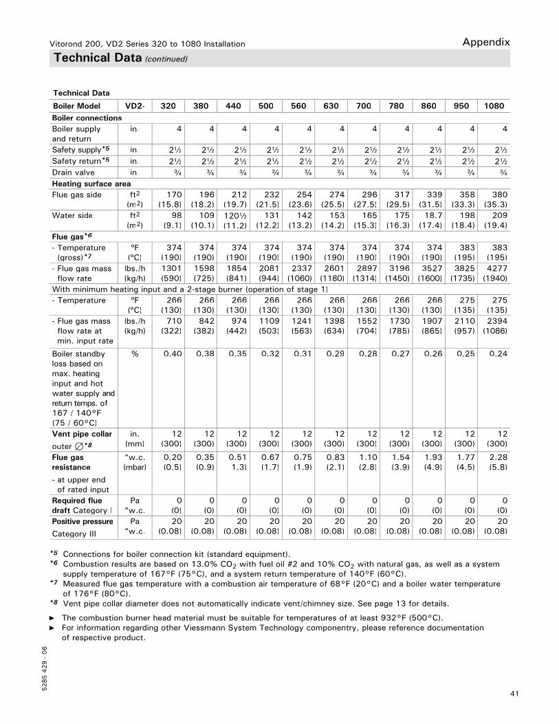
41
5285 4
29 -
06
Vitorond 200, VD2 Series 320 to 1080 Installation AppendixTechnical Data (continued)
Technical Data
Boiler Model VD2- 320 380 440 500 560 630 700 780 860 950 1080Boiler connectionsBoiler supply and return
in. 4 4 4 4 4 4 4 4 4 4 4
Safety supply*5 in. 2b 2b 2b 2b 2b 2b 2b 2b 2b 2b 2bSafety return*5 in. 2b 2b 2b 2b 2b 2b 2b 2b 2b 2b 2bDrain valve in. c c c c c c c c c c cHeating surface areaFlue gas side ft2
(m2)170
(15.8)196
(18.2)212
(19.7)232
(21.5)254
(23.6)274
(25.5)296
(27.5)317
(29.5)339
(31.5)358
(33.3)380
(35.3)Water side ft2
(m2)98
(9.1)109
(10.1)120b(11.2)
131(12.2)
142 (13.2)
153 (14.2)
165 (15.3)
175(16.3)
18.7(17.4)
198 (18.4)
209 (19.4)
Flue gas*6
- Temperature(gross)*7
ºF(ºC)
374 (190)
374 (190)
374 (190)
374(190)
374 (190)
374 (190)
374 (190)
374(190)
374(190)
383 (195)
383 (195)
- Flue gas massflow rate
lbs./h(kg/h)
1301 (590)
1598(725)
1854(841)
2081(944)
2337 (1060)
2601(1180)
2897(1314)
3196(1450)
3527(1600)
3825(1735)
4277(1940)
With minimum heating input and a 2-stage burner (operation of stage 1)- Temperature ºF
(ºC)266
(130)266
(130)266
(130)266
(130)266
(130)266
(130)266
(130)266
(130)266
(130)275
(135)275
(135)- Flue gas massflow rate at min. input rate
lbs./h(kg/h)
710 (322)
842 (382)
974 (442)
1109(503)
1241 (563)
1398(634)
1552(704)
1730(785)
1907(865)
2110(957)
2394(1086)
Boiler standby loss based on max. heatinginput and hot water supply andreturn temps. of167 / 140°F (75 / 60°C)
% 0.40 0.38 0.35 0.32 0.31 0.29 0.28 0.27 0.26 0.25 0.24
Vent pipe collar
outer 7*8
in. (mm)
12(300)
12(300)
12(300)
12(300)
12 (300)
12(300)
12(300)
12(300)
12(300)
12(300)
12(300)
Flue gas resistance
- at upper endof rated input
“w.c. (mbar)
0.20 (0.5)
0.35(0.9)
0.511.3)
0.67(1.7)
0.75 (1.9)
0.83(2.1)
1.10(2.8)
1.54(3.9)
1.93(4.9)
1.77(4.5)
2.28(5.8)
Required flue draft Category I
Pa “w.c.
0 (0)
0 (0)
0(0)
0(0)
0 (0)
0 (0)
0 (0)
0(0)
0(0)
0 (0)
0 (0)
Positive pressure
Category III
Pa “w.c.
20(0.08)
20(0.08)
20(0.08)
20(0.08)
20 (0.08)
20(0.08)
20(0.08)
20(0.08)
20(0.08)
20(0.08)
20(0.08)
*5 Connections for boiler connection kit (standard equipment).*6 Combustion results are based on 13.0% CO2 with fuel oil #2 and 10% CO2 with natural gas, as well as a system
supply temperature of 167°F (75°C), and a system return temperature of 140°F (60°C).*7 Measured flue gas temperature with a combustion air temperature of 68°F (20°C) and a boiler water temperature
of 176°F (80°C).*8 Vent pipe collar diameter does not automatically indicate vent/chimney size. See page 13 for details.
The combustion burner head material must be suitable for temperatures of at least 932°F (500°C). For information regarding other Viessmann System Technology componentry, please reference documentation
of respective product.

Vitorond 200, VD2 Series 320 to 1080 Installation
5285 4
29 -
06
42

43
5285 4
29 -
06
Vitorond 200, VD2 Series 320 to 1080 Installation
Tec
hnic
al in
form
atio
n su
bjec
t to
cha
nge
witho
ut n
otic
e.Pr
inte
d on
env
ironm
enta
lly f
riend
ly
(rec
ycle
d an
d re
cycl
able
) pa
per.
5285 4
29 -
06
Vitorond 200, VD2 Series 320 to 1080 Installation


![Supporting Information · 1•DACH 412, 429(sh) 429[+310] 412[-205] +515 1• DPEA 412, 429(sh) 429[+49] 412[-23] +72 Electronic Supplementary Material (ESI) for Chemical Communications](https://img.pdfslide.us/doc/110x75/60006f2e07a4443f3067d9e9/supporting-1adach-412-429sh-429310-412-205-515-1a-dpea-412-429sh.jpg)