Embed Size (px)
Citation preview
© 2015 Engineers Without Borders USA. All Rights Reserved Page 1 of 28
524 – Draft Final Design Report
Community: Bondo
Country: Kenya
Chapter: Hope College
Project ID(s): # 01186
Submittal Date: March 19, 2016
Authors: Brenden , Emma , Landon , Luke , Michelle , Tom Mentors: Courtney , Adam , Joseph
Acknowledgements The Project Leads and Mentor Team acknowledge that:
CAP The chapter reviewed the accompanying 524 – Draft Final Design Report Instructions for accurate completion of this report.
CAP
The PMEL lead has reviewed the 901B – Program Impact and Monitoring Report Template and is prepared to update the report during the upcoming trip. The chapter acknowledges that the completed 901B is required with the eventual submittal of the 526 – Post-Implementation Report.
CAP
The PMEL lead acknowledges that the 905 – Program Logic Framework is required as an appendix to the 901 and 901B reports.
CAP
The project monitoring indicators were selected at the post-assessment phase and documented in the 522 – Post-Assessment Report. The PMEL lead is prepared to gather updated results for the monitoring indicators on this trip and those results will be included in the 526 – Post-Implementation Report.
CAP
The team has included the Draft 903 – Implementation Agreement as an appendix to this report.
CAP
The most current contact information is updated in this report and all other reports included with this submittal.
CAP
Any new or additional member to the Mentor Team has included their resume, 404 – Mentor Statement of Intent, and 408 – Application to become a Professional Mentor for an EWB-USA Project.
524 – Draft Final Design Report Hope College - EWB Kenya, Bondo, #01186
© 2015 Engineers Without Borders USA. All Rights Reserved Page 2 of 28
We, the project team leadership confirm that the above information and tasks have been completed and that this report presents a complete design which meets the normal engineering standard of care for this type of facility. Landon 3/18/16 __________________________________________________________ __________________________________________________ Project Lead Printed Name Project Lead Signature Date Adam 3/18/16 _________________________________________________________________________________________________________________________________________ Mentor Printed Name Mentor Signature Date Or Courtney 3/18/16 _________________________________________________________________________________________________________________________________________ Faculty Advisor Printed Name Faculty Advisor Signature Date I have reviewed the subject project. I am qualified by education and experience to design this type of project. In my best engineering judgement, this report does its best to develop a complete and comprehensive design. The design presented within this report meets my standard of quality and is ready for review by the Technical Advisory Committee. Adam 3/18/16 _________________________________________________________________________________________________________________________________________ REIC Printed Name REIC Signature Date
524 – Draft Final Design Report Hope College - EWB Kenya, Bondo, #01186
© 2015 Engineers Without Borders USA. All Rights Reserved Page 3 of 28
Table of Contents Part I –Administrative Information .................................................................................................. 4
1.0 Contact Information .......................................................................................................... 4 2.0 Budget .............................................................................................................................. 5
3.0 Project Discipline(s) ......................................................................................................... 7
4.0 Number of People Impacted ............................................................................................ 7 5.0 Professional Mentor Resume(s) ...................................................................................... 7
5.1 Names and Qualifications of Designers ........................................................................... 8 Part II – Pre-Assessment Report .................................................................................................... 9
1.0 Executive Summary ......................................................................................................... 9 2.0 Facility Design ................................................................................................................ 10
2.1 Description of the Proposed Facility................................................................................ 10 2.2 Description of Design and Calculations ......................................................................... 13
2.3 Drawings .......................................................................................................................... 22 3.0 Project Ownership .......................................................................................................... 22
4.0 Construction Plan ........................................................................................................... 23 5.0 Materials List and Cost Estimate ................................................................................... 25
6.0 Operation and Maintenance........................................................................................... 26 7.0 Sustainability .................................................................................................................. 26
7.1 Background..................................................................................................................... 26 7.2 Organizational Capacity of the Community................................................................... 27
7.3 Financial Capacity of the Community.............................................................................. 27
7.4 Technical Capacity of the Community ............................................................................ 27 7.5 Education ......................................................................................................................... 28
8.0 Site Assessment Activities ............................................................................................. 28 9.0 References ..................................................................................................................... 28
524 – Draft Final Design Report Hope College - EWB Kenya, Bondo, #01186
© 2015 Engineers Without Borders USA. All Rights Reserved Page 4 of 28
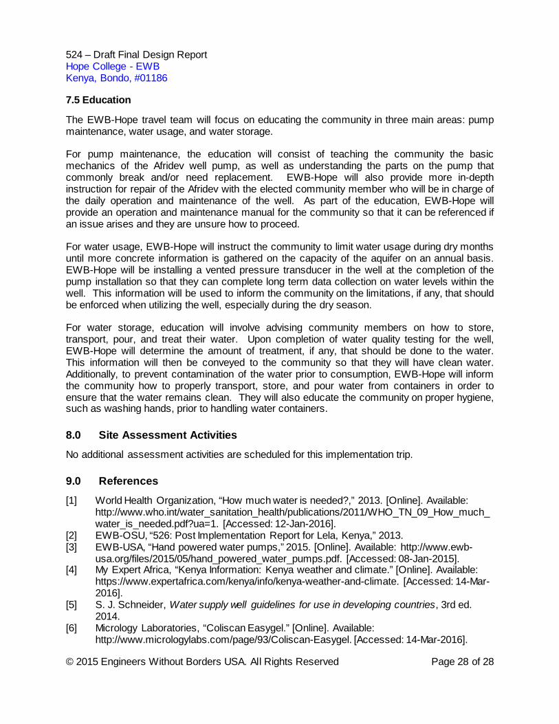
Attachments Construction Drawing Set D1: Drawing set cover page showing location & table of contents D2: Community map with points of interest D3: Plan view layout of well location D4: Well construction drawing (cross-sectional view of well) D5: Well pad construction details D6: Permanent enclosure drawing Appendix A – Mentor Resumes Appendix B – 903 Implementation Agreement Appendix C – Design Calculations Appendix D – Hydrogeologic Survey Report Appendix E – Pump Test Procedures Appendix F – O&M Manual Appendix G – Drilling Contract
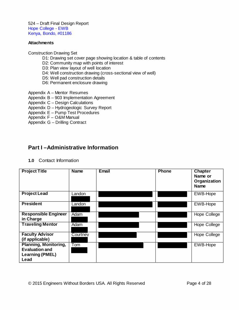
Part I –Administrative Information 1.0 Contact Information
Project Title Name
Phone Chapter Name or Organization Name
Project Lead Landon
EWB-Hope
President Landon
EWB-Hope
Responsible Engineer in Charge
Adam
Hope College
Traveling Mentor Adam
Hope College
Faculty Advisor (if applicable)
Courtney
Hope College
Planning, Monitoring, Evaluation and Learning (PMEL) Lead
Tom
EWB-Hope
524 – Draft Final Design Report Hope College - EWB Kenya, Bondo, #01186
© 2015 Engineers Without Borders USA. All Rights Reserved Page 5 of 28
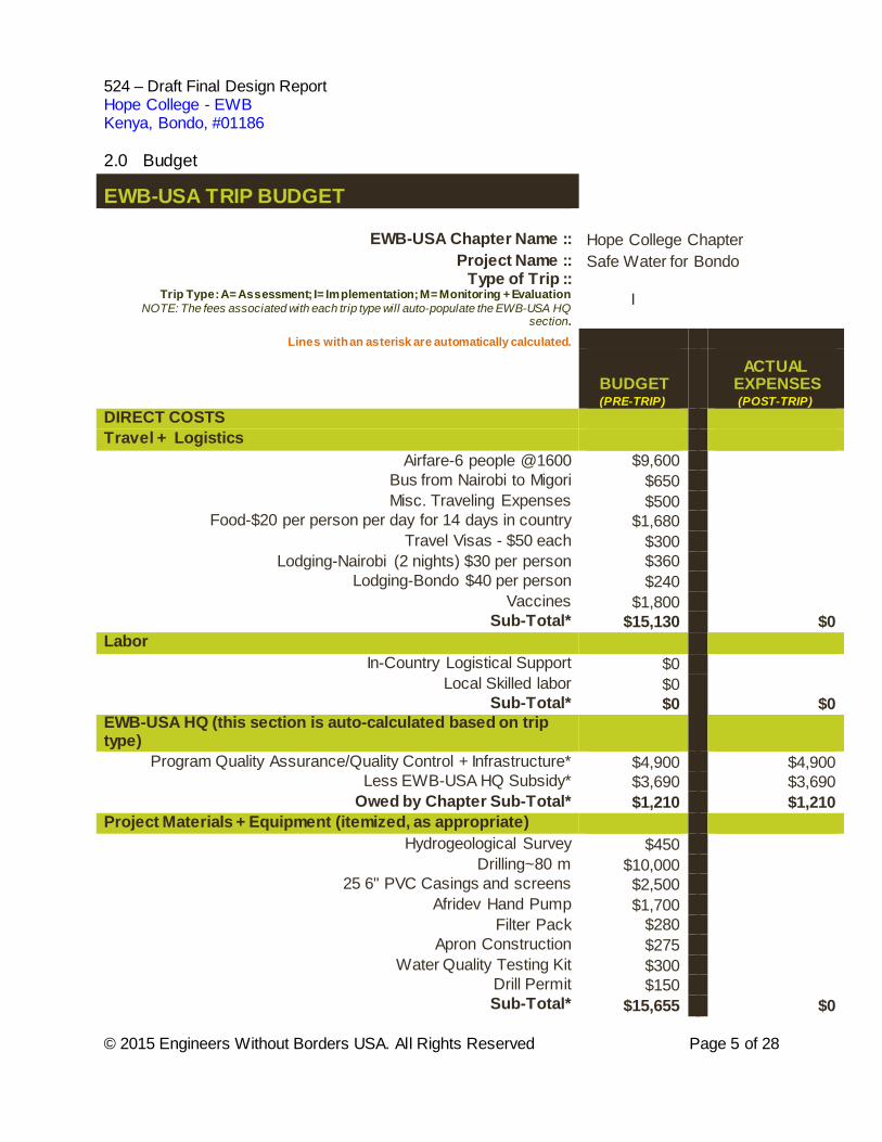
2.0 Budget
EWB-USA TRIP BUDGET
EWB-USA Chapter Name :: Hope College Chapter Project Name :: Safe Water for Bondo
Type of Trip :: Trip Type: A= Assessment; I= Implementation; M= Monitoring + Evaluation
NOTE: The fees associated with each trip type will auto-populate the EWB-USA HQ section.
I
Lines with an asterisk are automatically calculated.
BUDGET (PRE-TRIP)
ACTUAL EXPENSES
(POST-TRIP) DIRECT COSTS Travel + Logistics
Airfare-6 people @1600 $9,600 Bus from Nairobi to Migori $650 Misc. Traveling Expenses $500 Food-$20 per person per day for 14 days in country $1,680 Travel Visas - $50 each $300 Lodging-Nairobi (2 nights) $30 per person $360 Lodging-Bondo $40 per person $240 Vaccines $1,800 Sub-Total* $15,130 $0
Labor In-Country Logistical Support $0
Local Skilled labor $0 Sub-Total* $0 $0
EWB-USA HQ (this section is auto-calculated based on trip type)
Program Quality Assurance/Quality Control + Infrastructure* $4,900 $4,900 Less EWB-USA HQ Subsidy* $3,690 $3,690
Owed by Chapter Sub-Total* $1,210 $1,210 Project Materials + Equipment (itemized, as appropriate)
Hydrogeological Survey $450 Drilling~80 m $10,000 25 6" PVC Casings and screens $2,500 Afridev Hand Pump $1,700 Filter Pack $280 Apron Construction $275 Water Quality Testing Kit $300 Drill Permit $150 Sub-Total* $15,655 $0
524 – Draft Final Design Report Hope College - EWB Kenya, Bondo, #01186
© 2015 Engineers Without Borders USA. All Rights Reserved Page 6 of 28
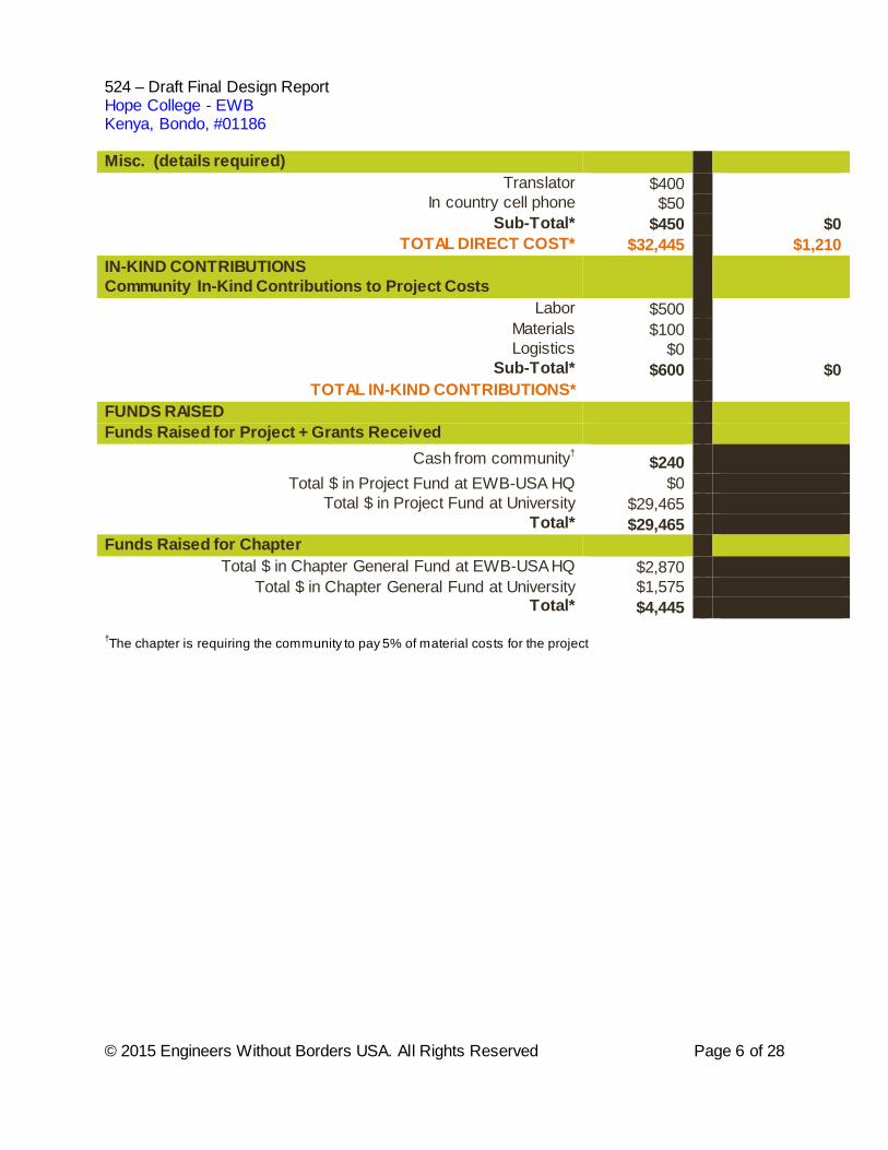
Misc. (details required) Translator $400
In country cell phone $50 Sub-Total* $450 $0
TOTAL DIRECT COST* $32,445 $1,210 IN-KIND CONTRIBUTIONS Community In-Kind Contributions to Project Costs
Labor $500 Materials $100 Logistics $0 Sub-Total* $600 $0
TOTAL IN-KIND CONTRIBUTIONS*
FUNDS RAISED
Funds Raised for Project + Grants Received Cash from community† $240
Total $ in Project Fund at EWB-USA HQ $0 Total $ in Project Fund at University $29,465
Total* $29,465 Funds Raised for Chapter
Total $ in Chapter General Fund at EWB-USA HQ $2,870 Total $ in Chapter General Fund at University $1,575
Total* $4,445 †The chapter is requiring the community to pay 5% of material costs for the project
524 – Draft Final Design Report Hope College - EWB Kenya, Bondo, #01186
© 2015 Engineers Without Borders USA. All Rights Reserved Page 7 of 28
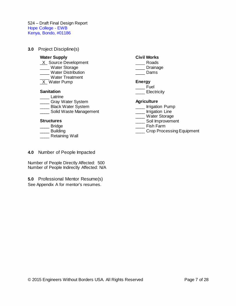
3.0 Project Discipline(s)
Water Supply _X_ Source Development ____ Water Storage ____ Water Distribution ____ Water Treatment _X_ Water Pump Sanitation ____ Latrine ____ Gray Water System ____ Black Water System ____ Solid Waste Management Structures ____ Bridge ____ Building ____ Retaining Wall
Civil Works ____ Roads ____ Drainage ____ Dams Energy ____ Fuel ____ Electricity Agriculture ____ Irrigation Pump ____ Irrigation Line ____ Water Storage ____ Soil Improvement ____ Fish Farm ____ Crop Processing Equipment
4.0 Number of People Impacted Number of People Directly Affected: 500 Number of People Indirectly Affected: N/A 5.0 Professional Mentor Resume(s) See Appendix A for mentor’s resumes.
524 – Draft Final Design Report Hope College - EWB Kenya, Bondo, #01186
© 2015 Engineers Without Borders USA. All Rights Reserved Page 8 of 28
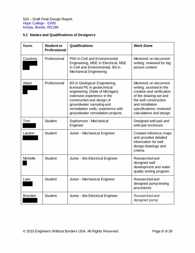
5.1 Names and Qualifications of Designers Name Student or
Professional Qualifications Work Done
Courtney
Professional PhD in Civil and Environmental Engineering, MSE in Electrical, MSE in Civil and Environmental, BS in Mechanical Engineering
Mentored on document writing; reviewed for big picture content
Adam
Professional BS in Geological Engineering, licensed PE in geotechnical engineering (State of Michigan), extensive experience in the construction and design of groundwater sampling and remediation wells, experience with groundwater remediation projects
Mentored on document writing; assisted in the creation and verification of the drawing set and the well construction and installation specifications; reviewed calculations and design
Tom
Student Sophomore - Mechanical Engineer
Designed well pad and well pad enclosure
Landon
Student
Junior - Mechanical Engineer Created reference maps and provided detailed information for well design drawings and criteria
Michelle
Student Junior - Bio-Electrical Engineer Researched and designed well development and water quality testing program
Luke
Student Junior - Mechanical Engineer
Researched and designed pump testing procedures
Brenden
Student Junior - Bio-Electrical Engineer Researched and designed pump
524 – Draft Final Design Report Hope College - EWB Kenya, Bondo, #01186
© 2015 Engineers Without Borders USA. All Rights Reserved Page 9 of 28
Part II – Pre-Assessment Report 1.0 Executive Summary
The Engineers Without Borders - Hope College Chapter (EWB-Hope) has completed this design report for the program in Bondo, Kenya (#01186, “Safe Water for Bondo”). This design report describes the design of a well and hand pump which will provide a water source to the community of Bondo. The activities related to the well design project will be completed during one implementation trip unless unexpected results are obtained during the first implementation trip, which would require revisions to the design and a second implementation trip. EWB-Hope is asking for approval to complete the installation of a deep groundwater well that will be operated by an Afridev hand pump, as a source development project for the community of Bondo, Kenya. The chapter is requesting to complete the installation of the well and the hand pump in one implementation trip, based on the requirement that all design parameters of an in-field checklist are met during the first implementation trip. The parameters that must be met are outlined in section 4.3 General Schedule and include that the newly installed well satisfies a minimum yield capacity requirement and all in-field water testing satisfies World Health Organization (WHO) standards for water quality. Additionally, adequate time must remain in the EWB-Hope travel schedule to install the pump properly and educate the community on use and maintenance of the pump. The goal of the project is to provide reliable, accessible, and safe water to the community of Bondo year-round. The source must provide water for approximately 500 residents within the small community of Bondo. The water source will be deemed safe for human consumption if it meets the WHO standards for drinking-water quality. The overall water quantity provided by the source will be deemed adequate if 15 liters per day per person is supplied based on the recommendations by WHO [1]. Bondo is located in the Migori district of southwest Kenya. Approximately 60 farming families (500 residents) live in compounds or homesteads in a one kilometer radius rural area and do not have access to a reliable and safe drinking water source. Women and children spend an average of two hours a day collecting surface water or well water from neighboring villages. The only surface water source in the community is a seasonal surface water pit that contains high concentrations of fecal coliforms and is not reliable year-round. Inspired by successful EWB water projects in nearby communities, the village formed a Water Council, also known as the Harambe Women’s Group, in 2012. The Water Council is modeled after and mentored by the Women’s Water Committee in the nearby community of Lela, who worked with the Engineers Without Borders Oregon State University (EWB-OSU) student chapter. The Water Council has made improving public health by establishing safe drinking water sources the community’s top priority. The draft for the 903 Implementation Agreement between all parties working to meet this overall goal is attached in Appendix B.
The water source development project is a new partnership between the community and EWB-Hope. The community application was reviewed in March 2014 by EWB-USA and the partnership between the Bondo community and the EWB-Hope chapter was approved in June 2014. An assessment trip was conducted in March 2015 to conduct surveys, complete GPS mapping of the community, and to sign the 902 Project Partnership Agreement. The EWB-
524 – Draft Final Design Report Hope College - EWB Kenya, Bondo, #01186
© 2015 Engineers Without Borders USA. All Rights Reserved Page 10 of 28
Hope chapter is willing to engage in a long-term partnership with the community in order to best realize their goals.
Calculations were performed to determine the amount of water that could be produced per person from the well using an Afridev hand pump. This calculation was based off of an approximate hand pump rate and the amount of people in the community. The complete calculations can be found in Appendix C.
Drawings supporting the design include location maps, site plans, and detailed drawings of the proposed well, well pad, and well pad enclosure. The full drawing set consists of seven drawings, including an index page. The drawing set can be found as an attachment at the end of this document.
The construction process includes drilling the well, developing the well, pump testing and water quality testing, building a well pad, and installing a hand pump. The role of EWB-Hope is to serve as the lead designer and collect data at each step of the process to determine if the process can continue as planned. The role of , the selected drilling contractor, is to provide all necessary construction equipment and skilled labor. will also transport all necessary materials to the construction site. The sequencing of events for this project include preparing and assembling equipment and materials at the project site, completing the borehole, installing the well, developing the well, conducting pump testing and water quality testing on the well, and installing the well pad, well pad enclosure, and a hand pump. In addition to construction activities, EWB-Hope will educate community members on the operation and maintenance of the hand pump and well. The key components of project sustainability are community ownership and a commitment to maintenance. The Water Council is the most important factor in the community ownership as they are responsible to collecting fees, maintaining an operation and maintenance account, and scheduling repairs. Training for maintaining the hand pump and well pad will be provided by EWB-Hope and . is also required to maintain a relationship with Bondo for three years after the implementation and will provide the expertise required to repair the system. Preventative maintenance checks will be performed by an elected community member once the well is installed and they will report problems to the water committee who will contact for repair. The Water Council’s maintenance fund will maintain a balance of $30(USD) annually to cover the cost of maintenance. 2.0 Facility Design
2.1 Description of the Proposed Facility
The community of Bondo, located in the southwest region of Kenya, has expressed a need for a clean, accessible, and sustainable source of water within their community borders. See drawing D-1: Site Location and Index for the community’s location within Kenya. EWB-Hope is proposing the installation of a deep well with a hand pump to provide a clean and sustainable water source to the Bondo community. There are no existing wells or sustainable surface water sources within the community, so water source development is necessary. Additionally, the buildings in the community are generally small so the installation of rainwater catchment systems is impractical as it is not cost effective or sustainable. A well is the most viable option to achieve
524 – Draft Final Design Report Hope College - EWB Kenya, Bondo, #01186
© 2015 Engineers Without Borders USA. All Rights Reserved Page 11 of 28
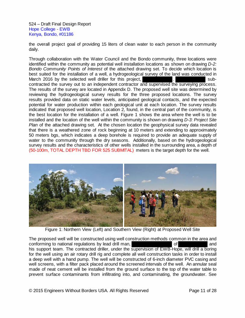
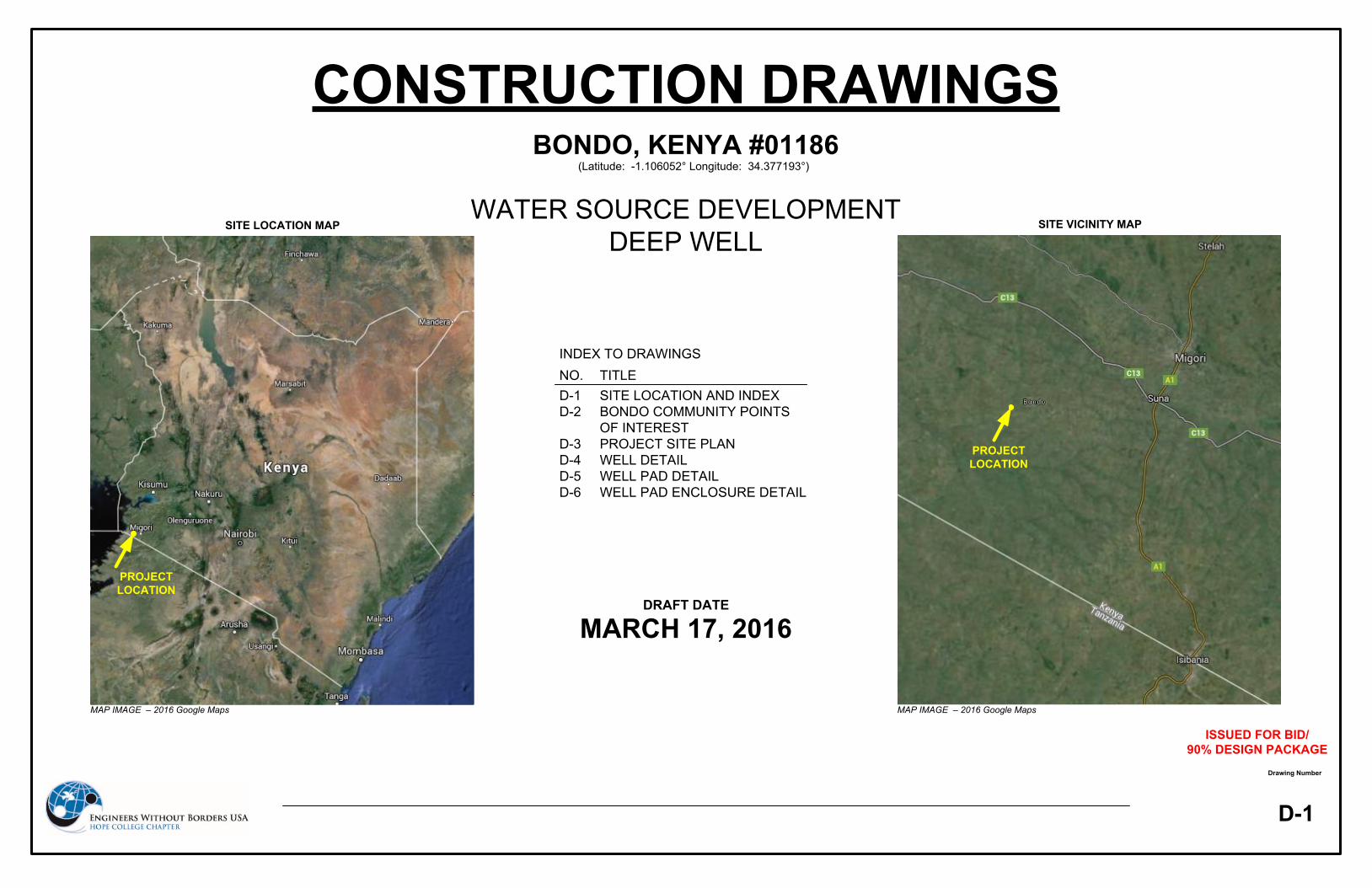
the overall project goal of providing 15 liters of clean water to each person in the community daily. Through collaboration with the Water Council and the Bondo community, three locations were identified within the community as potential well installation locations as shown on drawing D-2: Bondo Community Points of Interest of the attached drawing set. To decide which location is best suited for the installation of a well, a hydrogeological survey of the land was conducted in March 2016 by the selected well driller for this project, . sub-contracted the survey out to an independent contractor and supervised the surveying process. The results of the survey are located in Appendix D. The proposed well site was determined by reviewing the hydrogeological survey results for the three proposed locations. The survey results provided data on static water levels, anticipated geological contacts, and the expected potential for water production within each geological unit at each location. The survey results indicated that proposed well location, Location 2, found, in the central part of the community, is the best location for the installation of a well. Figure 1 shows the area where the well is to be installed and the location of the well within the community is shown on drawing D-3: Project Site Plan of the attached drawing set. At the chosen location the geophysical survey data revealed that there is a weathered zone of rock beginning at 10 meters and extending to approximately 50 meters bgs, which indicates a deep borehole is required to provide an adequate supply of water to the community through the dry seasons. Additionally, based on the hydrogeological survey results and the characteristics of other wells installed in the surrounding area, a depth of (50-100m, TOTAL DEPTH TBD FOR 525 SUBMITAL) meters is the target depth for the well.
Figure 1: Northern View (Left) and Southern View (Right) at Proposed Well Site
The proposed well will be constructed using well construction methods common in the area and conforming to national regulations by lead drill man, of and his support team. The contracted driller, under the supervision of EWB-Hope, will drill a boring for the well using an air rotary drill rig and complete all well construction tasks in order to install a deep well with a hand pump. The well will be constructed of 6-inch diameter PVC casing and well screens, with a filter pack placed around the screened intervals of the well. An annular seal made of neat cement will be installed from the ground surface to the top of the water table to prevent surface contaminants from infiltrating into, and contaminating, the groundwater. See
524 – Draft Final Design Report Hope College - EWB Kenya, Bondo, #01186
© 2015 Engineers Without Borders USA. All Rights Reserved Page 12 of 28
drawing D-4: Well Detail for a detailed drawing showing the specific materials that will be used for construction of the well and the anticipated depths of proposed well construction. Once constructed, the well will be developed in order to improve the overall capacity of the well and to remove any fine sediment within the well and filter pack which could be generated during installation. The well development technique of choice is air lifting, due to the availability of the equipment in country and its effectiveness in developing deep wells. After well development is completed, water quantity and water quality tests will be conducted on the well. Drawdown, yield, and recovery measurements of the source will be collected by performing a step drawdown test and a 24-hour constant rate test. Water quality testing will be conducted on water samples collected from the well to check for bacterial coliforms as well as other secondary water quality parameters. Water quality test results will be compared to the WHO’s regulatory limits to determine if additional water treatment is required prior to installing a pump in the well.
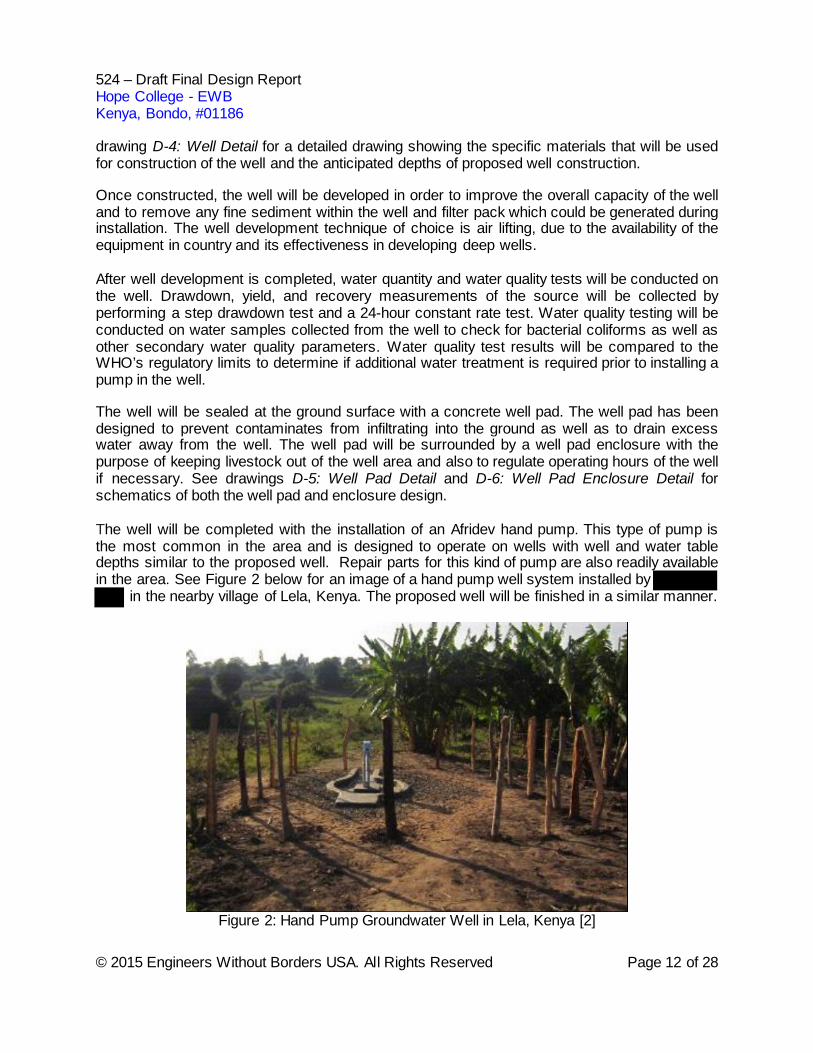
The well will be sealed at the ground surface with a concrete well pad. The well pad has been designed to prevent contaminates from infiltrating into the ground as well as to drain excess water away from the well. The well pad will be surrounded by a well pad enclosure with the purpose of keeping livestock out of the well area and also to regulate operating hours of the well if necessary. See drawings D-5: Well Pad Detail and D-6: Well Pad Enclosure Detail for schematics of both the well pad and enclosure design. The well will be completed with the installation of an Afridev hand pump. This type of pump is the most common in the area and is designed to operate on wells with well and water table depths similar to the proposed well. Repair parts for this kind of pump are also readily available in the area. See Figure 2 below for an image of a hand pump well system installed by
in the nearby village of Lela, Kenya. The proposed well will be finished in a similar manner.
Figure 2: Hand Pump Groundwater Well in Lela, Kenya [2]
524 – Draft Final Design Report Hope College - EWB Kenya, Bondo, #01186
© 2015 Engineers Without Borders USA. All Rights Reserved Page 13 of 28
In total, the construction and implementation process will span the course of 14 days in the field. The installation of the well and the hand pump will be will be complete in one implementation trip provided the water production rate of the well meets the engineer’s design requirements and water quality meets all applicable WHO regulations. EWB-Hope will use an in-field checklist to verify that all criteria are met prior to installing a pump in the well.
2.2 Description of Design and Calculations
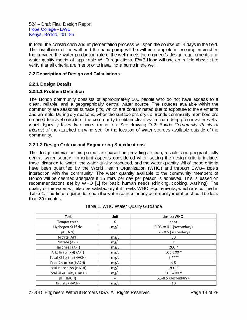
2.2.1 Design Details 2.2.1.1 Problem Definition The Bondo community consists of approximately 500 people who do not have access to a clean, reliable, and a geographically central water source. The sources available within the community are seasonal surface pits, which are contaminated due to exposure to the elements and animals. During dry seasons, when the surface pits dry up, Bondo community members are required to travel outside of the community to obtain clean water from deep groundwater wells, which typically takes two hours round trip. See drawing D-2: Bondo Community Points of Interest of the attached drawing set, for the location of water sources available outside of the community. 2.2.1.2 Design Criteria and Engineering Specifications The design criteria for this project are based on providing a clean, reliable, and geographically central water source. Important aspects considered when setting the design criteria include: travel distance to water, the water quality produced, and the water quantity. All of these criteria have been quantified by the World Health Organization (WHO) and through EWB–Hope’s interaction with the community. The water quantity available to the community members of Bondo will be deemed adequate if 15 liters per day per person is achieved. This is based on recommendations set by WHO [1] for basic human needs (drinking, cooking, washing). The quality of the water will also be satisfactory if it meets WHO requirements, which are outlined in Table 1. The time required to reach the water source for any community member should be less than 30 minutes.
Table 1. WHO Water Quality Guidance
Test Unit Limits (WHO) Temperature C none
Hydrogen Sulfide mg/L 0.05 to 0.1 (secondary) pH (API) -- 6.5-8.5 (secondary)
Nitrite (API) mg/L 50 Nitrate (API) mg/L 3
Hardness (API) mg/L 200 * Alkalinity (kH) (API) mg/L 100-200 *
Total Chlorine (HACH) mg/L 5 **** Free Chlorine (HACH) mg/L < 5
Total Hardness (HACH) mg/L 200 * Total Alkalinity (HACH) mg/L 100-200 *
pH (HACH) -- 6.5-8.5 (secondary)+ Nitrate (HACH) mg/L 10
524 – Draft Final Design Report Hope College - EWB Kenya, Bondo, #01186
© 2015 Engineers Without Borders USA. All Rights Reserved Page 14 of 28
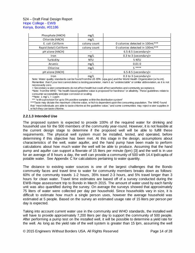
Phosphate (HACH) mg/L Chloride (HACH) mg/L E. coli Coliform colony count 0 colonies detected in 100mL***
Rapid (total) Coliform colony count 0 colonies detected in 100mL*** pH alone (HACH) -- 6.5-8.5 (secondary)+
Iron mg/L 0.3 to 3 (secondary)+ Turbidity NTU 5 NTU Arsenic mg/L 0.01 0
Chlorine mg/L 5 **** pH alone (HACH) -- 6.5-8.5 (secondary)+
Iron mg/L 0.3 to 3 (secondary)+ Note: Water quality standards can be found from the US EPA (epa.gov) and the World Health Organization (w ho.int). Remember that if your test cannot detect a testing parameter, mark it as “undetectable” or similar abbreviation, as it is not necessarily zero. + Secondary w ater contaminants do not affect health but could affect aesthetics and community acceptance. *Note: from the WHO: “No health-based guideline value is proposed for hardness” or alkalinity. These guidelines relate to consumer acceptability and pipe corrosion or scaling. **Note: 1 mg/ L = 1 ppm *** “w ith a provision for up to 5% positive samples w ithin the distribution system”
****Taste may dictate the maximum chlorine value, w hich is dependent upon the consuming population. The WHO found that “most individuals are able to taste chlorine at the guideline value,” and some communities may reject w ater supplies in w hich they can taste chlorine.
2.2.1.3 Intended Use The proposed system is expected to provide 100% of the required water for drinking and household use for the 500 members of the community year-round. However, it is not feasible at the current design stage to determine if the proposed well will be able to fulfill these requirements. The physical well system must be installed, tested, and operated, before determining if this objective has been met. At this stage in the design, assumptions about characteristics of the well, water aquifer, and the hand pump have been made to perform calculations about how much water the well will be able to produce. Assuming that the hand pump and aquifer can support a flowrate of 15 liters per minute (lpm) [3] and the well is in use for an average of 8 hours a day, the well can provide a community of 500 with 14.4 lpd/capita of potable water. See Appendix C for calculations pertaining to water quantity. The distance to existing water sources is one of the largest challenges that the Bondo community faces and travel time to water for community members breaks down as follows: 60% of the community travels 1-2 hours, 35% travel 2-3 hours, and 5% travel longer than 3 hours for clean water. Travel time estimates are based off of a survey conducted during the EWB-Hope assessment trip to Bondo in March 2015. The amount of water used by each family unit was also quantified during the survey. On average the surveys showed that approximately 75 liters of water were collected per day per household. Since households vary in size, it is difficult to estimate how much a single person uses, however the average household was estimated at 5 people. Based on the survey an estimated usage rate of 15 liters per person per day is expected. Taking into account current water use in the community and WHO standards, the installed well will have to provide approximately 7,200 liters per day to support the community of 500 people. After performing a pump test on the installed well, it will be possible to determine a yield rate for the well. As long as the yield rate of the well system is greater than 15 lpm, assuming the well
524 – Draft Final Design Report Hope College - EWB Kenya, Bondo, #01186
© 2015 Engineers Without Borders USA. All Rights Reserved Page 15 of 28
will be in use for 8 hours a day, the water requirements should be met. Other wells around the region have recorded pump tests that ranged from 20 to 50 lpm. This satisfies the necessary flow rate in order to provide 7,200 liters per day for the community.
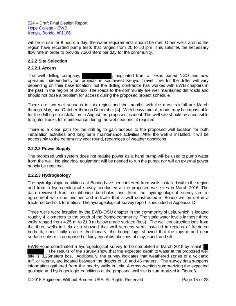
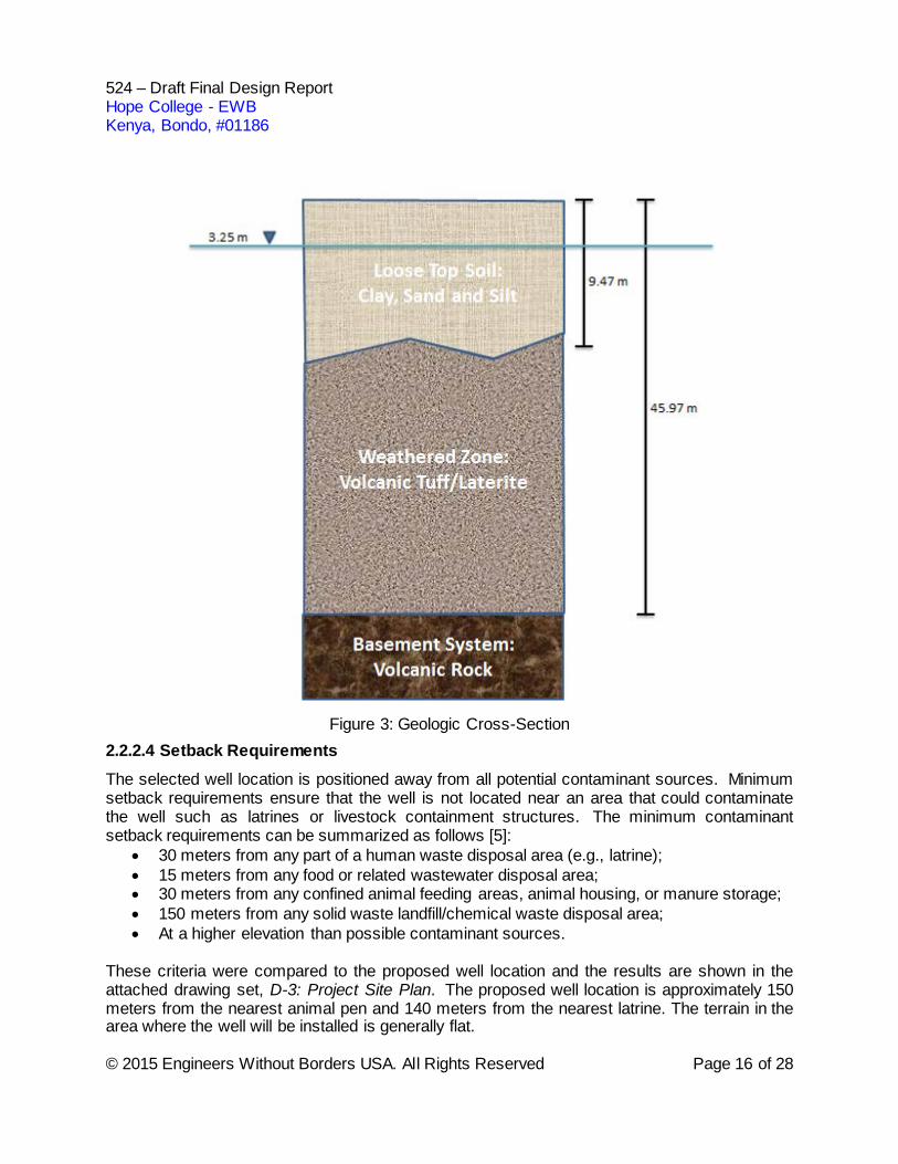
2.2.2 Site Selection 2.2.2.1 Access The well drilling company, , originated from a Texas based NGO and now operates independently on projects in southwest Kenya. Travel time for the driller will vary depending on their base location, but the drilling contractor has worked with EWB chapters in the past in the region of Bondo. The roads to the community are well maintained dirt roads and should not pose a problem for access during the proposed project schedule. There are two wet seasons in this region and the months with the most rainfall are March through May, and October through December [4]. With heavy rainfall, roads may be impassable for the drill rig so installation in August, as proposed, is ideal. The well site should be accessible to lighter trucks for maintenance during the wet seasons, if required. There is a clear path for the drill rig to gain access to the proposed well location for both installation activities and long term maintenance activities. After the well is installed, it will be accessible to the community year round, regardless of weather conditions. 2.2.2.2 Power Supply The proposed well system does not require power as a hand pump will be used to pump water from the well. No electrical equipment will be needed to run the pump, nor will an external power supply be required. 2.2.2.3 Hydrogeology The hydrolgeologic conditions at Bondo have been inferred from wells installed within the region and from a hydrogeological survey conducted at the proposed well sites in March 2016. The data reviewed from neighboring boreholes and from the hydrogeological survey are in agreement with one another and indicate that a well constructed in Bondo will be set in a fractured bedrock formation. The hydrogeological survey report is included in Appendix D. Three wells were installed by the EWB-OSU chapter in the community of Lela, which is located roughly 4 kilometers to the south of the Bondo community. The static water levels in these three wells ranged from 4.25 m to 21.9 m below grade surface (bgs). The well construction logs from the three wells in Lela also showed that well screens were installed in regions of fractured bedrock, specifically granite. Additionally, the boring logs showed that the topsoil and near surface subsoil is composed of fairly equal distributions of clay, sand, and silt. EWB-Hope coordinated a hydrogeological survey to be completed in March 2016 by IIsaiah
. The results of the survey show that the expected depth to water at the proposed well site is 3.25meters bgs. Additionally, the survey indicates that weathered zones of a volcanic tuff, or laterite, are located between the depths of 10 and 46 meters. The survey data supports information gathered from the nearby wells in Lela. A cross-section summarizing the expected geologic and hydrogeologic conditions at the proposed well site is summarized in Figure3.
524 – Draft Final Design Report Hope College - EWB Kenya, Bondo, #01186
© 2015 Engineers Without Borders USA. All Rights Reserved Page 16 of 28
Figure 3: Geologic Cross-Section
2.2.2.4 Setback Requirements The selected well location is positioned away from all potential contaminant sources. Minimum setback requirements ensure that the well is not located near an area that could contaminate the well such as latrines or livestock containment structures. The minimum contaminant setback requirements can be summarized as follows [5]:
• 30 meters from any part of a human waste disposal area (e.g., latrine); • 15 meters from any food or related wastewater disposal area; • 30 meters from any confined animal feeding areas, animal housing, or manure storage; • 150 meters from any solid waste landfill/chemical waste disposal area; • At a higher elevation than possible contaminant sources.
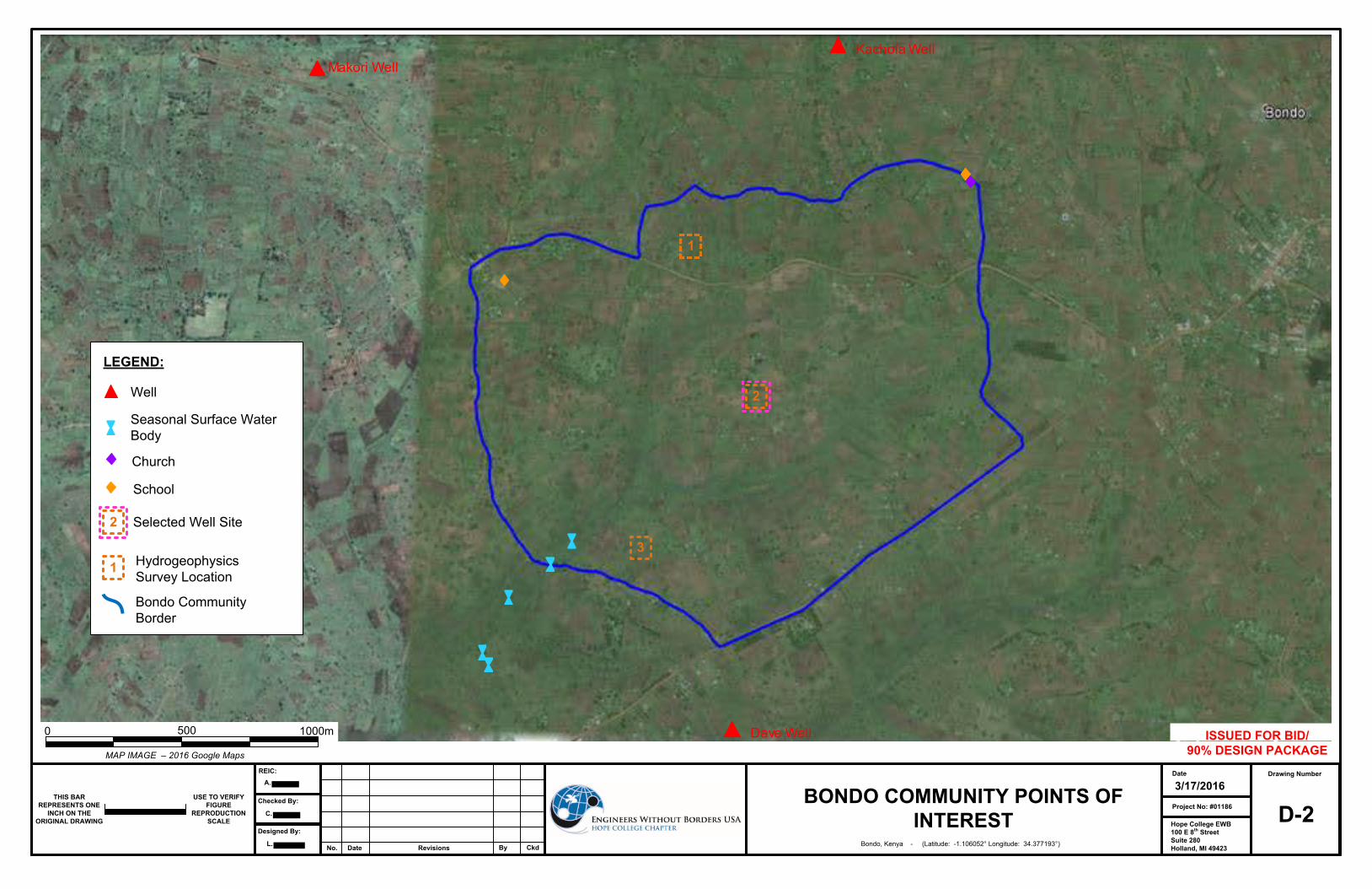
These criteria were compared to the proposed well location and the results are shown in the attached drawing set, D-3: Project Site Plan. The proposed well location is approximately 150 meters from the nearest animal pen and 140 meters from the nearest latrine. The terrain in the area where the well will be installed is generally flat.
524 – Draft Final Design Report Hope College - EWB Kenya, Bondo, #01186
© 2015 Engineers Without Borders USA. All Rights Reserved Page 17 of 28
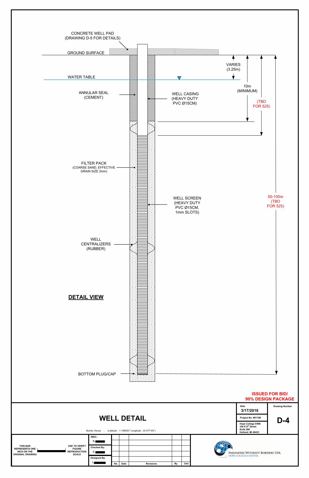
2.2.2.5 Location Relative to Existing Water Sources There are no previous water distribution systems present in the community. 2.2.2.6 Property Ownership In order to alleviate disputes over project ownership, the proposed well will be installed on public land and the Water Council will hold the deed for this land. 2.2.3 Well Design and Specifications The basic parts of the well that will be installed are the well casing, casing centralizers, well screen, filter pack, annular seal, and surface seal. The central part of the well, termed the casing, provides a route for transporting water from the well screen(s) to the ground surface. The casing is encompassed by an annular seal from the ground surface to the top of the groundwater aquifer, thus preventing surface contaminants from vertically transporting down to the well screen and contaminating the aquifer. Once at the depth(s) of the target aquifer, well screen(s) are installed and surrounded by a filter pack. The filter pack is placed in the annulus around the well screen to prevent fine sediment or particles from entering the well. The well screen is constructed of a perforated manufactured screen to allow groundwater to enter into the well assembly. Casing centralizers are used to align the well casing and well screen assembly within the middle of the borehole so that the filter pack material and the annular seal can be installed to fully surround the well components. Well construction details, including material and depth are outlined in the following sections and described on drawing D-4: Well Detail of the attached drawing set.
2.2.3.1 Conceptual Plan A site plan showing the location of the proposed well is shown in drawing D-3: Project Site Plan of the attached drawing set, of the attached drawing set. There is a clear path for the drill rig to gain access to the proposed well location for both installation activities and long term maintenance activities. The location of the well is on public land and is located approximately 150 meters away from the closest household and 140 meters away from the closest latrine. This location is optimal as it is in an open area and accessible to the public.
2.2.3.2 Well Depth and Diameter The targeted depth of the well is (50-100m, TOTAL DEPTH TBD FOR 525 SUBMITAL) meters bgs as determined from the results of the hydrogeological survey and through talking with Mr.
of . The hydrogeological survey showed a high potential of water bearing rock units between the depths of 10 and 46 meters bgs. This proposed well depth is also comparable to nearby wells that range in depth from 60 meters to 100 meters. The diameter of the drill bit being used with the air-rotary drill rig will be 8 inches, which is anticipated to cut an eight to ten inch diameter borehole during drilling. The well casing and screen assembly will have a 6 inch (nominal) diameter. The selected depth and diameter for the well matches accepted construction practices for wells within the region.
524 – Draft Final Design Report Hope College - EWB Kenya, Bondo, #01186
© 2015 Engineers Without Borders USA. All Rights Reserved Page 18 of 28
2.2.3.3 Target Aquifer The expected depth to groundwater at the drilling location is 3.25meters bgs and the expected screen interval depths range from XX to XX (TBD FOR 525) meters bgs. The targeted screen depths are based on the results of the hydrogeological survey completed in March 2016.
2.2.3.4 Casing The casing selected for construction of the well is a 6 inch heavy duty polyvinyl chloride (PVC) casing. This type of PVC casing is used at the majority of the wells surveyed near the Bondo community and is recommended under the advisement of the drilling contractor. Additionally, PVC was selected as it is available to the driller and is a cheaper alternative to steel casing. Although PVC is weaker than steel, it has been successfully used in construction of nearby wells. As PVC is prone to distortion under heat and pressure, care will be taken when installing the cement annular seal and concrete well pad which come in contact with the well casing as the curing process of concrete will produce heat.
2.2.3.5 Casing Centralizer Casing centralizers are used to hold the casing in the center of the borehole and preserve the annular space for the filter pack and annular seal. The casing centralizers that will be used are rubber centralizers and will be placed at the top and bottom of all screened intervals of the well.
2.2.3.6 Well Screen
The well screen will be a manufactured 6 inch heavy duty PVC screen with 1-millimeter slots at a XX (TBD FOR 525) spacing. This type of screen is in use in the majority of nearby wells and is recommended by the selected drilling contractor, . This screen was selected as it will provide adequate communication with the groundwater aquifer in order to provide the well with comparable, or even higher, water production rates to that of the installed hand pump.
2.2.3.7 Filter Pack Coarse sand will be used as a filter pack around the well screen. The coarse sand will have an effective grain size of 2 millimeters in diameter so that it will not clog the well screens. As the screened intervals are expected to be in fractured bedrock, minimal filtering capacity of the surrounding geologic formation is required from the filter pack. In this instance the filter pack will serve to keep the well centralized in the borehole and essentially increase the diameter of the well.
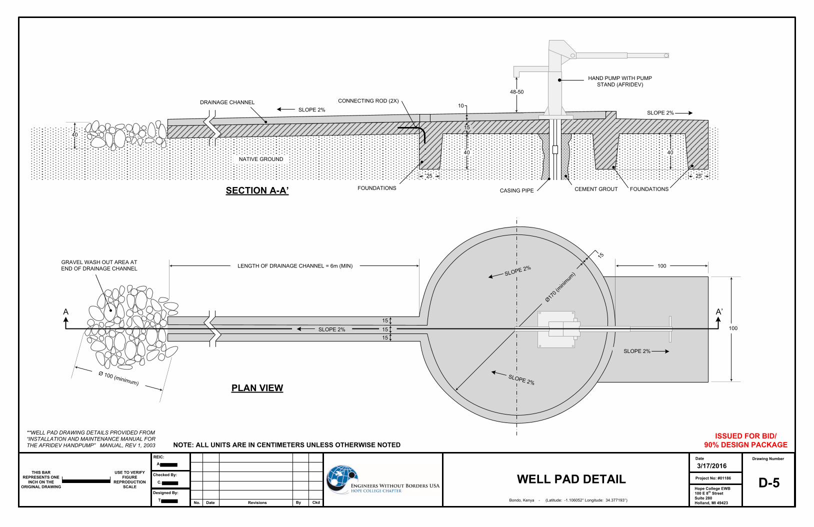
2.2.3.8 Surface Seal The surface seal consists of two components: the annular seal at the top of the well casing and the surface seal in the form of a well pad. The annular seal will be a neat cement mixture comprised of cement and water. The seal will be set using a tremie pipe and will extend from the ground surface down to the top of the groundwater table, or no less than 10 meters bgs, whichever is deeper. The surface seal will consist of a concrete well pad as shown in drawing D-5: Well Pad Details, of the attached drawing set. This pad will provide a barrier around the borehole to prevent contaminates from entering the well and to prevent erosion around the pump stand. The well
524 – Draft Final Design Report Hope College - EWB Kenya, Bondo, #01186
© 2015 Engineers Without Borders USA. All Rights Reserved Page 19 of 28
pad will consist of a concrete round base with a diameter of approximately 2 meters. The edge of the concrete pad will have a lip or curb raised up 10 centimeters to keep water from spilling off the center of the pad. This pad will be sloped towards a concrete drainage channel to direct excess/spilled water away from the well pad. At the end of the concrete drainage channel a rock bed will be placed to discourage erosion and mud.
2.2.4 Well Completion and Testing 2.2.4.1 Well Screen Development Well screen development will be performed after the installment of the well and will be used to improve the capacity and function of the well. The main goal of well screen development for this project is to remove fine particles from the filter pack and the surrounding formation thereby reducing the cloudiness of water. A wait-period of a minimum of 24 hours will be included before the well screen development is completed to allow for the cement grout used for the annular seal to set. This ensures that the well screen is not damaged by drawing cement slurry into the well screen during development. The well screen development process can be conducted using many different methods to improve the quality and consistency of the well. The development method that will be used on the Bondo well will be air lifting because it is a very efficient method that requires minimal equipment and is low in cost. Also, the equipment is readily available to the drilling contractor selected for this project. Air lifting well development is completed by injecting compressed air into the well to displace water within the well and lift it out of the top of the well casing. Air is injected into the well through a temporarily installed small diameter pipe which can be raised and lowered throughout the screened intervals of the well. After a sufficient amount of air is injected so as to force water to the top of the casing, the air is shut off, thus allowing the water to fall and for the air to continue to rise. This action creates pulsing of water in and out of the well screen and filter pack and results in the loosening and removal of fine particles. Following several on-off cycles of air development, airlift pumping is completed by injecting a constant flowrate of air into the well, allowing water to rise up the well casing and flow out onto the ground surface. Total well depth and depth to water measurement will be made in the well prior to and post air lifting. This information will indicate if material is removed from the well and will confirm that no damage to the well screen occurred during the development process. A minimum of three borehole volumes (anticipated to be approximately 2000 gallons) will be purged from the well and water samples will be collected and tested at various intervals of this process to ensure that the well is properly developed. The well will be deemed to be developed properly when adequate quantities of water continuously measure lower than 3 Nephelometric Turbidity Units (NTU) on a handheld turbidity meter. 2.2.4.2 Pump Testing
In order to assess drawdown, yield, and recovery a step drawdown test and 24-hour constant rate test will be conducted. See Appendix E for the procedures for each test. These tests are completed to confirm that the flowrate of the selected hand pump (Afridev) for the well will not exceed the yield rate of the well.
524 – Draft Final Design Report Hope College - EWB Kenya, Bondo, #01186
© 2015 Engineers Without Borders USA. All Rights Reserved Page 20 of 28
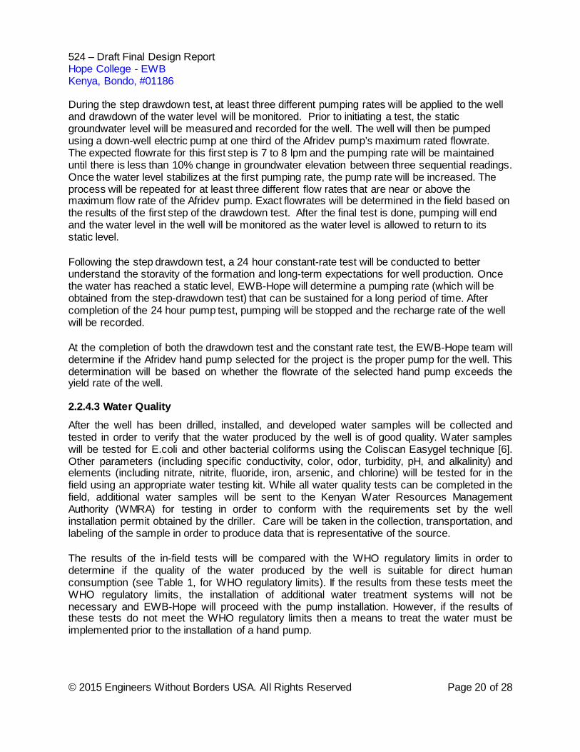
During the step drawdown test, at least three different pumping rates will be applied to the well and drawdown of the water level will be monitored. Prior to initiating a test, the static groundwater level will be measured and recorded for the well. The well will then be pumped using a down-well electric pump at one third of the Afridev pump’s maximum rated flowrate. The expected flowrate for this first step is 7 to 8 lpm and the pumping rate will be maintained until there is less than 10% change in groundwater elevation between three sequential readings. Once the water level stabilizes at the first pumping rate, the pump rate will be increased. The process will be repeated for at least three different flow rates that are near or above the maximum flow rate of the Afridev pump. Exact flowrates will be determined in the field based on the results of the first step of the drawdown test. After the final test is done, pumping will end and the water level in the well will be monitored as the water level is allowed to return to its static level. Following the step drawdown test, a 24 hour constant-rate test will be conducted to better understand the storavity of the formation and long-term expectations for well production. Once the water has reached a static level, EWB-Hope will determine a pumping rate (which will be obtained from the step-drawdown test) that can be sustained for a long period of time. After completion of the 24 hour pump test, pumping will be stopped and the recharge rate of the well will be recorded. At the completion of both the drawdown test and the constant rate test, the EWB-Hope team will determine if the Afridev hand pump selected for the project is the proper pump for the well. This determination will be based on whether the flowrate of the selected hand pump exceeds the yield rate of the well. 2.2.4.3 Water Quality After the well has been drilled, installed, and developed water samples will be collected and tested in order to verify that the water produced by the well is of good quality. Water samples will be tested for E.coli and other bacterial coliforms using the Coliscan Easygel technique [6]. Other parameters (including specific conductivity, color, odor, turbidity, pH, and alkalinity) and elements (including nitrate, nitrite, fluoride, iron, arsenic, and chlorine) will be tested for in the field using an appropriate water testing kit. While all water quality tests can be completed in the field, additional water samples will be sent to the Kenyan Water Resources Management Authority (WMRA) for testing in order to conform with the requirements set by the well installation permit obtained by the driller. Care will be taken in the collection, transportation, and labeling of the sample in order to produce data that is representative of the source. The results of the in-field tests will be compared with the WHO regulatory limits in order to determine if the quality of the water produced by the well is suitable for direct human consumption (see Table 1, for WHO regulatory limits). If the results from these tests meet the WHO regulatory limits, the installation of additional water treatment systems will not be necessary and EWB-Hope will proceed with the pump installation. However, if the results of these tests do not meet the WHO regulatory limits then a means to treat the water must be implemented prior to the installation of a hand pump.
524 – Draft Final Design Report Hope College - EWB Kenya, Bondo, #01186
© 2015 Engineers Without Borders USA. All Rights Reserved Page 21 of 28
2.2.4.4 Well Construction Log After drilling and installing all components of the well, a well drilling log and construction report will be created by the drilling contractor. The contractor is required to send these documents to the WMRA per the well installation permit. The contractor will also provide these documents to EWB-Hope for future reference.
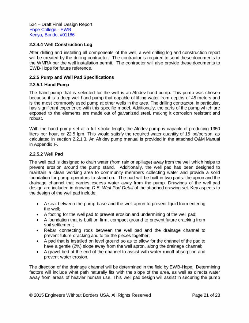
2.2.5 Pump and Well Pad Specifications 2.2.5.1 Hand Pump The hand pump that is selected for the well is an Afridev hand pump. This pump was chosen because it is a deep well hand pump that capable of lifting water from depths of 45 meters and is the most commonly used pump at other wells in the area. The drilling contractor, in particular, has significant experience with this specific model. Additionally, the parts of the pump which are exposed to the elements are made out of galvanized steel, making it corrosion resistant and robust. With the hand pump set at a full stroke length, the Afridev pump is capable of producing 1350 liters per hour, or 22.5 lpm. This would satisfy the required water quantity of 15 lpd/person, as calculated in section 2.2.1.3. An Afridev pump manual is provided in the attached O&M Manual in Appendix F. 2.2.5.2 Well Pad The well pad is designed to drain water (from rain or spillage) away from the well which helps to prevent erosion around the pump stand. Additionally, the well pad has been designed to maintain a clean working area to community members collecting water and provide a solid foundation for pump operators to stand on. The pad will be built in two parts: the apron and the drainage channel that carries excess water away from the pump. Drawings of the well pad design are included in drawing D-5: Well Pad Detail of the attached drawing set. Key aspects to the design of the well pad include:
• A seal between the pump base and the well apron to prevent liquid from entering the well;
• A footing for the well pad to prevent erosion and undermining of the well pad; • A foundation that is built on firm, compact ground to prevent future cracking from
soil settlement; • Rebar connecting rods between the well pad and the drainage channel to
prevent future cracking and to tie the pieces together; • A pad that is installed on level ground so as to allow for the channel of the pad to
have a gentle (2%) slope away from the well apron, along the drainage channel; • A gravel bed at the end of the channel to assist with water runoff absorption and
prevent water erosion. The direction of the drainage channel will be determined in the field by EWB-Hope. Determining factors will include what path naturally fits with the slope of the area, as well as directs water away from areas of heavier human use. This well pad design will assist in securing the pump
524 – Draft Final Design Report Hope College - EWB Kenya, Bondo, #01186
© 2015 Engineers Without Borders USA. All Rights Reserved Page 22 of 28
and help to extend the life of the pump and well by carrying away elements that could erode and corrode the pump stand.
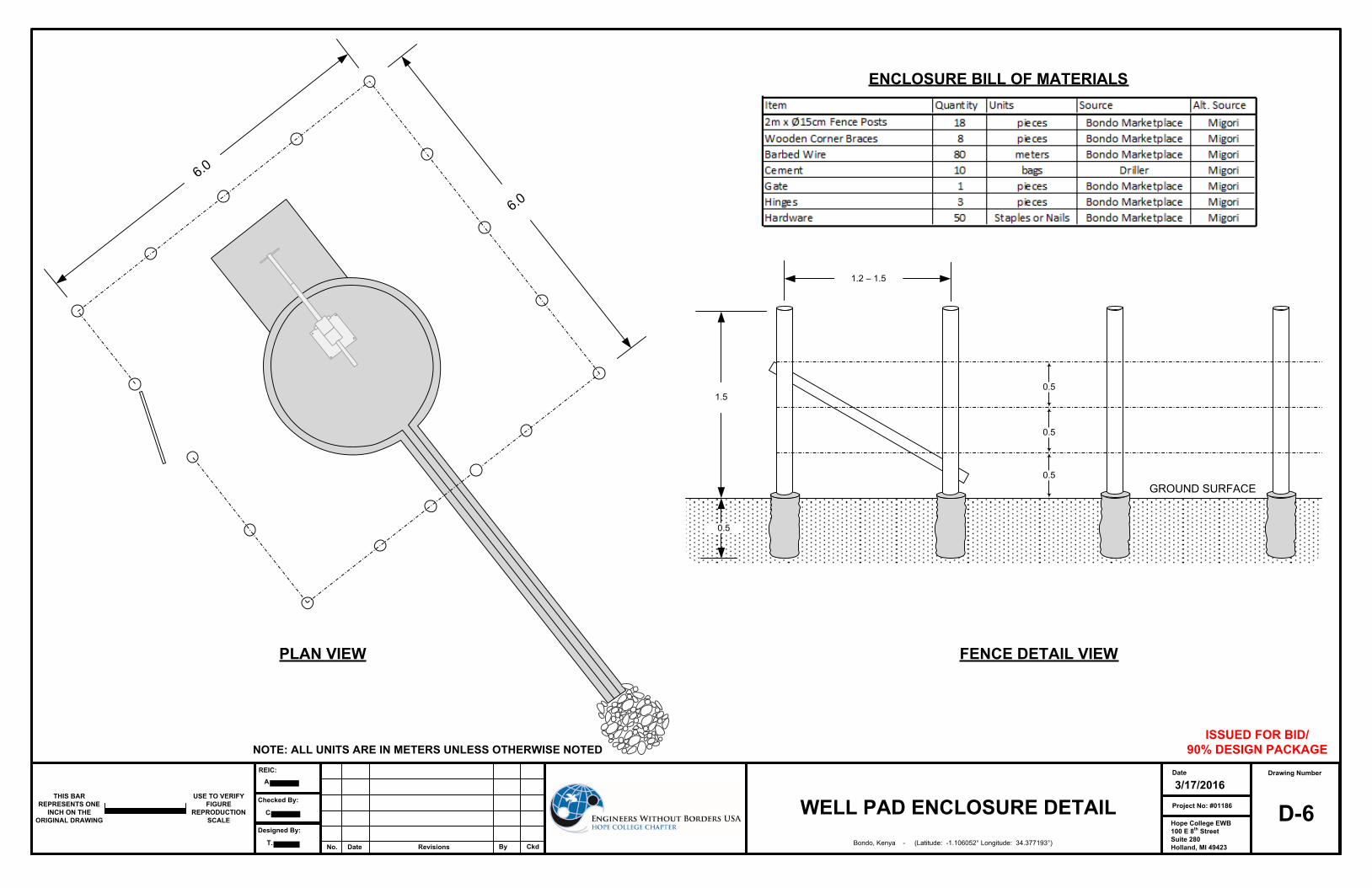
2.2.5.3 Well Pad Enclosure The well pad will be enclosed by a 6 meter square fence enclosure consisting of a barbed wire strung around fence posts. This enclosure will serve the purpose of preventing large animals from accessing the well head area and will also help maintain the flow of human traffic near the well. The fencing will be constructed using either manufactured wood (4x4) or locally available tree branches (minimum 15 centimeter diameter) and this will be determined during the trip depending on availability. The fence posts will be positioned 1.2 to 1.5 meters apart and three rows of wire will run along the posts, thus surrounding the well pad to a height of 1.5 meter. The fence posts will be buried into holes at a depth of 1/3 the height of the post and concrete will be poured into the holes to adequately secure the posts. A hinged gate will be installed to allow access to the well. The gate will either be bought pre-constructed or made out of shorter pieces of wood and attached by hinges. The well pad enclosure specifications are provided in drawing D-6: Well Pad Enclosure Detail of the attached drawing set.
2.3 Drawings
Please see the drawing set attached at the end of this document for complete design details. D1: Site Location and Index D2: Bondo Community Points of Interest D3: Project Site Plan D4: Well Detail D5: Well Pad Detail D6: Well Pad Enclosure Detail
2.4 524 - Draft Final Design Report Review Comments
This section is pending project engineer’s review. 3.0 Project Ownership The constructed facilities will be owned and operated by the Water Council of the Harambe Women’s Group. They are currently responsible for fundraising and collecting funds in order to contribute to 5% of the cost of the material costs required for the well implementation project. In order to collect funds for this project, the community is charging each member who wishes to use the well an upfront fee, followed by a monthly usage fee. Initially, these community charges will be put towards the 5% contribution of the material cost of the well, however once the well is installed, the revenue flow will be redirected to fully fund operation and maintenance charges. Funds are recorded by the Water Council’s treasurer and then deposited each month in the group’s bank account in the nearby town of Migori. This funding agreement was discussed with the community in March 2015, during EWB-Hope assessment trip in which the project partnership agreement was signed. The proposed well location is currently owned by a family from the community, but is in the process of being donated to the Harambe Women’s Group and thus becoming public land. During weekly phone calls with the community, it has been explicitly stated that the family who
524 – Draft Final Design Report Hope College - EWB Kenya, Bondo, #01186
© 2015 Engineers Without Borders USA. All Rights Reserved Page 23 of 28
owns the property currently is donating this land for public well use. The legal documentation of this change still needs to happen, and EWB-Hope is helping to facilitate this process. Once this land is public, a copy of the title deed to this land will be sent to the Water Resource Management Authority by the well driller in order to obtain the rights to drill a well and to document the installation of the well. The Water Council will be responsible for operation of the well and will appoint or elect one community member to perform maintenance. This community member will be paid a small stipend through the revenue brought in by monthly dues and will be hired after the well has been installed. This hired worker will be responsible for operation of the well and also for determining when repairs are required for the well and pump. Weekly and monthly checks will be performed and are outlined in more detail in Section 6.0 Operation and Maintenance. If the required maintenance falls outside of the worker’s qualifications, then the well driller,
, will be contacted by the hired community member and will be paid to perform the required maintenance. The well driller’s contract requires him to be responsible for maintenance on the well during the first three years of use.
4.0 Construction Plan 4.1 Responsible Parties EWB-Hope will take the role of construction management and oversight during the well drilling and construction process. In addition to this, EWB-Hope will provide technical engineering expertise as needed and will direct the drilling contractor on how to complete construction tasks if necessary. Also serving in a construction management and project supervision role are the executive members of the Water Council.
is the selected drilling contractor for this project and the lead drill man, Mr. will instruct his drilling team during the labor and construction of the well. During the well
implementation process, will provide construction expertise and all the materials required to drill and install the components of the well. Once the well is installed, testing of the well will be conducted and documented by , under the guidance of EWB-Hope. All permits and documentation required for the installation of the well by the Kenyan Water Resources Management Authority (WMRA) and will be prepared and handled by the drilling contractor. Once the well is drilled and installation is complete, will provide education to EWB-Hope members about the general pump operation and maintenance procedures. EWB-Hope will be responsible for educating the community members on the operation of the pump and general maintenance requirements for the well pad. Additionally, EWB-Hope will be responsible for the construction and installation of the well pad enclosure fencing at the conclusion of the well installation project. EWB-Hope will encourage the participation of Bondo community members in the construction of this fencing 4.2 Driller Qualifications Melchizedeck , the selected drill-man, is part of the Texas based NGO, , and has received training on well drilling from them directly. He has a positive reputation among those who have previously worked with him in the well drilling process. He has collaborated with
524 – Draft Final Design Report Hope College - EWB Kenya, Bondo, #01186
© 2015 Engineers Without Borders USA. All Rights Reserved Page 24 of 28
EWB - OSU in the installation of multiple wells in Lela, Kenya and they had very positive experiences, indicating that they would choose to work with him and his drilling company on future projects. They also commented on his willingness to help with a variety of steps in the well-drilling process, including assisting with the acquisition of government permits and other pre-travel requirements. In the past he was also willing to return to the well installation site after a period of time to hold workshops, thus ensuring that the community knew how to properly maintain the well and pump. In moving forward with the implementation process, we believe that
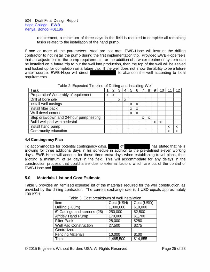
is a safe and reliable choice for our drill-man based on his reputation among other EWB chapters. Before drilling can occur, several documents will be prepared and handled by . The results of the hydrogeological survey must be documented and sent to the WMRA to ensure that drilling can take place. Once approved, a permit will be obtained from the WMRA verifying that the drilling can commence. A contract has been drawn up between EWB-Hope and to determine which tools and materials will be needed, projected costs, and the expected schedule (Appendix G, CONTRACT IN PROCESS, REQUEST FOR QUOTE PROVIDED IN 524). As requested in the contract, the driller must also provide a license to verify that he is credible and that the process will carry out as planned. After drilling, the overall construction process must be submitted to the WMRA in order to close out the permit. All post-drilling documentation, including logs of drilling operations and pump test data, will be provided to EWB-Hope by as outlined in the contract. 4.3 General Schedule For the implementation of the well, the drilling contractor has presented EWB-Hope with an expected timeline showing the schedule for drilling, constructing, and completing the well. The general timeline for the implementation process is outlined in Table 2. The first two days will involve the drilling contractor preparing equipment and the drill site for the installation of the boring and well. Days three and four will consist of drilling the borehole. Days five and six will involve the construction of the well and the development of the well. The step drawdown pump test and the 24-hour pump test will be conducted and analyzed on days seven and eight. After the capacity of the well is determined, days nine and ten will involve constructing the concrete well pad including fixing the pedestal for the hand pump to be installed on. Following the completion of the well installation tasks, EWB-Hope will review the pump test data, and water quality testing data, as well as assess the amount of time left in the travel schedule to determine if it is appropriate to install the Afridev hand pump in the well. The pump will be installed during the first implementation trip provided the following parameters are satisfied:
• Well Capacity: pump test data indicates that the maximum flowrate of the Afridev hand pump does not exceed the yield rate of the well;
• Water Quality: all in-field water quality testing parameters meet WHO standards;
• Schedule: sufficient time remains in EWB-Hope’s travel itinerary to install the pump and to educate the community on operation and maintenance of the well. To satisfy this
524 – Draft Final Design Report Hope College - EWB Kenya, Bondo, #01186
© 2015 Engineers Without Borders USA. All Rights Reserved Page 25 of 28
requirement, a minimum of three days in the field is required to complete all remaining tasks related to the installation of the hand pump.
If one or more of the parameters listed are not met, EWB-Hope will instruct the drilling contractor to not install the pump during the first implementation trip. Provided EWB-Hope feels that an adjustment to the pump requirements, or the addition of a water treatment system can be installed on a future trip to put the well into production, then the top of the well will be sealed and locked up for completion on a future trip. If the well does not show the ability to be a future water source, EWB-Hope will direct to abandon the well according to local requirements.
Table 2: Expected Timeline of Drilling and Installing Well Task 1 2 3 4 5 6 7 8 9 10 11 12 Preparation/ Assembly of equipment x x Drill of borehole x x Install well casings x x Install filter pack x x Well development x x Step drawdown and 24-hour pump testing x x Build well pad with pedestal x x Install hand pump x x Community education x x
4.4 Contingency Plan To accommodate for potential contingency days, of has stated that he is allowing for three additional days in his schedule in addition to the pre-defined eleven working days. EWB-Hope will account for these three extra days when establishing travel plans, thus allotting a minimum of 14 days in the field. This will accommodate for any delays in the construction process that could arise due to external factors which are out of the control of EWB-Hope and . 5.0 Materials List and Cost Estimate
Table 3 provides an itemized expense list of the materials required for the well construction, as provided by the drilling contractor. The current exchange rate is 1 USD equals approximately 100 KSH.
Table 3: Cost breakdown of well installation Item Cost (KSH) Cost (USD) Drilling (~80m) 1,000,000 $10,000 6” Casings and screens (25) 250,000 $2,500 Afridev Hand Pump 170,000 $1,700 Filter Pack 28,000 $280 Well Pad Construction 27,500 $275 Centralizers - - Fencing Materials 10,000 $100 Total 1,485,500 $14,855
524 – Draft Final Design Report Hope College - EWB Kenya, Bondo, #01186
© 2015 Engineers Without Borders USA. All Rights Reserved Page 26 of 28
6.0 Operation and Maintenance
Once the well is completed and the hand pump is installed, the two long term maintenance concerns are the hand pump and the well pad. Therefore, regularly scheduled preventative maintenance checks of both the well pad and hand pump are required. An elected member of the community will be responsible for ensuring that the well is properly maintained by performing preventative maintenance checks throughout the lifespan of the well. For the hand pump, preventative maintenance checks will be organized into weekly and monthly checks. Weekly checks will consist of checking to ensure that flange bolts, flange nuts, fulcrum pin nuts, and hanger pin nuts on the hand pump remain tight and do not show signs of wear. Monthly checks will include checking if any fasteners or parts of the pump head are missing, checking for unusual noises when using the pump, checking if the pump stand is unstable during operation, and carrying out leakage and discharge tests (see Operation and Maintenance Manual in Appendix F for full details). Under the direction of the elected maintenance person, large maintenance tasks and repairs on the hand pump will be completed by , who has access to all replacement parts for the pump. The well pad that the pump sits on provides protection from external contaminants infiltrating into the ground and running along the well/boring annulus to the groundwater table. Therefore, proper care of the well pad is required to keep a tight seal at the ground surface. Regular checks should be made and measures should be taken to ensure that cracks in the well pad are repaired as needed. Directions for repairing well pad cracks are outlined in the Operation and Maintenance Manual in Appendix F. The EWB-Hope travel team will hold operation and maintenance training with the elected official and members of the Water Council during the implementation trip. At a minimum, the meeting will be targeted toward educating the proper representatives within the Water Council on hand pump operation, repairs, and preventative checks that are to be completed on a weekly and monthly basis. Based on information received from and repair records of other Afridev hand pumps operating in the area, an estimated $30 (USD) is required, annually to keep the well operational, however some of the local hand pumps have been operated for multiple years with no maintenance costs. The community will be expected to maintain a minimum of $30 in their bank account to cover the cost of maintenance on an annual basis. Community members will be charged a monthly fee to use the well which will be deposited in the Harambe Women’s Group’s bank account in Migori in order to fund all repairs.
7.0 Sustainability
7.1 Background
The sustainability of this project depends on three key components: community ownership and commitment to maintenance, prevention of contaminates from entering the well, and prevention of depleting the aquifer. The impact of the latter two can be minimized through sound engineering practices but all three depend on participation from the community.
524 – Draft Final Design Report Hope College - EWB Kenya, Bondo, #01186
© 2015 Engineers Without Borders USA. All Rights Reserved Page 27 of 28
7.2 Organizational Capacity of the Community
The Bondo community has an established Water Council within the Harambe Women’s Group which consists of a Chairperson, a Treasurer, a Secretary, a co-representative for each position, and a coordinator, for a total of seven committee members. The co-representative’s role is to assist their respective representative’s duties and to fill in for their representative as required. The coordinator maintains contact with EWB-Hope and reports all communication back to the committee. The community holds elections for all positions every year. The committee meets biweekly to discuss a variety of topics including general water concerns in the community, as well as specific details for the EWB water project. The committee has been very involved throughout the entire project. During the assessment trip the committee accompanied the EWB-Hope team on all data collection tasks. They provided access to all community members by holding community meetings and also one-on-one interviews where more in-depth surveys could be conducted. EWB-Hope has continued to communicate with the committee on a weekly basis through the committee coordinator, thus keeping the community involved in the design process. In this way, the committee has been able to collect input from community members about the different design options during the alternative analysis and also to determine three possible well locations within the community boundaries.
7.3 Financial Capacity of the Community
The community understands that they are responsible for the 5% cash contribution, as well as 100% of the Operation and Maintenance (O&M) fees. The community has been raising funds for the 5% contribution by collecting one-time membership fees of 300 Kenyan shillings (KSH) from community members to join a water co-op. They have collected 20,000 KSH to date through these fees. They will continue to maintain an O&M fund by collecting a monthly fee of 20 KSH from members of the water co-op. If a community member opts to not join the co-op, then they will still be able to collect water from the well for 5 KSH per 10 liter bucket. All collected funds by the treasurer are deposited into the council’s bank account by a minimum of 2 members of the council. The projected O&M costs for the well are approximately 3,000 KSH shillings per repair (according to the drilling contractor) and a well typically requires one repair per year. Based on the monthly collection fees, the community will be able to sustain the well financially.
7.4 Technical Capacity of the Community
The main technology being implemented in this project is a hand pump and specifically the Afridev pump. Because this pump is being used at neighboring wells, the community has basic familiarity with pump operation. Once the pump is in place and the well has been completed, the community will be taught how to use and maintain the pump. The community will be supplied with an O&M manual for the pump and a member of the community will be appointed as the well maintainer who will be taught how to recognize when maintenance is required. Additionally, as part of the drilling contract, the drilling contractor will be in contact with the community for a minimum of three years after the installation of the pump to provide assistance with repairs of the pump.
524 – Draft Final Design Report Hope College - EWB Kenya, Bondo, #01186
© 2015 Engineers Without Borders USA. All Rights Reserved Page 28 of 28
7.5 Education
The EWB-Hope travel team will focus on educating the community in three main areas: pump maintenance, water usage, and water storage. For pump maintenance, the education will consist of teaching the community the basic mechanics of the Afridev well pump, as well as understanding the parts on the pump that commonly break and/or need replacement. EWB-Hope will also provide more in-depth instruction for repair of the Afridev with the elected community member who will be in charge of the daily operation and maintenance of the well. As part of the education, EWB-Hope will provide an operation and maintenance manual for the community so that it can be referenced if an issue arises and they are unsure how to proceed. For water usage, EWB-Hope will instruct the community to limit water usage during dry months until more concrete information is gathered on the capacity of the aquifer on an annual basis. EWB-Hope will be installing a vented pressure transducer in the well at the completion of the pump installation so that they can complete long term data collection on water levels within the well. This information will be used to inform the community on the limitations, if any, that should be enforced when utilizing the well, especially during the dry season. For water storage, education will involve advising community members on how to store, transport, pour, and treat their water. Upon completion of water quality testing for the well, EWB-Hope will determine the amount of treatment, if any, that should be done to the water. This information will then be conveyed to the community so that they will have clean water. Additionally, to prevent contamination of the water prior to consumption, EWB-Hope will inform the community how to properly transport, store, and pour water from containers in order to ensure that the water remains clean. They will also educate the community on proper hygiene, such as washing hands, prior to handling water containers. 8.0 Site Assessment Activities
No additional assessment activities are scheduled for this implementation trip. 9.0 References
[1] World Health Organization, “How much water is needed?,” 2013. [Online]. Available: http://www.who.int/water_sanitation_health/publications/2011/WHO_TN_09_How_much_water_is_needed.pdf?ua=1. [Accessed: 12-Jan-2016].
[2] EWB-OSU, “526: Post Implementation Report for Lela, Kenya,” 2013. [3] EWB-USA, “Hand powered water pumps,” 2015. [Online]. Available: http://www.ewb-
usa.org/files/2015/05/hand_powered_water_pumps.pdf. [Accessed: 08-Jan-2015]. [4] My Expert Africa, “Kenya Information: Kenya weather and climate.” [Online]. Available:
https://www.expertafrica.com/kenya/info/kenya-weather-and-climate. [Accessed: 14-Mar-2016].
[5] S. J. Schneider, Water supply well guidelines for use in developing countries, 3rd ed. 2014.
[6] Micrology Laboratories, “Coliscan Easygel.” [Online]. Available: http://www.micrologylabs.com/page/93/Coliscan-Easygel. [Accessed: 14-Mar-2016].
ISSUED FOR BID/90% DESIGN PACKAGE
Drawing Number
D-1
CONSTRUCTION DRAWINGSBONDO, KENYA #01186
WATER SOURCE DEVELOPMENTDEEP WELL
(Latitude: -1.106052° Longitude: 34.377193°)
INDEX TO DRAWINGSNO. TITLED-1 SITE LOCATION AND INDEXD-2 BONDO COMMUNITY POINTS
OF INTERESTD-3 PROJECT SITE PLAND-4 WELL DETAILD-5 WELL PAD DETAILD-6 WELL PAD ENCLOSURE DETAIL
DRAFT DATE
MARCH 17, 2016
SITE LOCATION MAP SITE VICINITY MAP
PROJECT LOCATION
PROJECT LOCATION
MAP IMAGE – 2016 Google Maps MAP IMAGE – 2016 Google Maps
Drawing Number
D-2
Date
3/17/2016
Hope College EWB100 E 8th StreetSuite 280Holland, MI 49423Bondo, Kenya - (Latitude: -1.106052° Longitude: 34.377193°)
BONDO COMMUNITY POINTS OF INTEREST
THIS BAR REPRESENTS ONE
INCH ON THE ORIGINAL DRAWING
USE TO VERIFY FIGURE
REPRODUCTION SCALE
REIC:
Designed By:
Checked By:
A.
Project No: #01186
No. Date Revisions By Ckd
ISSUED FOR BID/90% DESIGN PACKAGE
0 1000m500
MAP IMAGE – 2016 Google Maps
Dave Well
Kachola WellMakori Well
1
3
2
LEGEND:
1 Hydrogeophysics Survey Location
2 Selected Well Site
School
KEY:HouseSurface WaterSchoolChurchWellProposed Well
Church
Seasonal Surface Water Body
KEY:HouseSurface WaterSchoolChurchWellProposed WellWell
L.
Bondo Community Border
C.
Drawing Number
D-3
Date
3/17/2016
Hope College EWB100 E 8th StreetSuite 280Holland, MI 49423Bondo, Kenya - (Latitude: -1.106052° Longitude: 34.377193°)
PROJECT SITE PLAN LOGOTHIS BAR
REPRESENTS ONE INCH ON THE
ORIGINAL DRAWING
USE TO VERIFY FIGURE
REPRODUCTION SCALE
REIC:
Designed By:
Checked By:
A.
Project No: #01186
No. Date Revisions By CkdL.
0 100m50 ISSUED FOR BID/90% DESIGN PACKAGE
Proposed Well Site
LEGEND:
Identified Latrines
Animal Holding/Housing
House
C.
ISSUED FOR BID/90% DESIGN PACKAGE
Drawing Number
D-4
Date
3/17/2016
Hope College EWB100 E 8th StreetSuite 280Holland, MI 49423Bondo, Kenya - (Latitude: -1.106052° Longitude: 34.377193°)
WELL DETAIL
THIS BAR REPRESENTS ONE
INCH ON THE ORIGINAL DRAWING
USE TO VERIFY FIGURE
REPRODUCTION SCALE
REIC:
Designed By:
Checked By:
A.
Project No: #01186
No. Date Revisions By Ckd
WELL CASING(HEAVY DUTY PVC Ø15CM)
WELL SCREEN(HEAVY DUTY PVC Ø15CM, 1mm SLOTS)
GROUND SURFACE
WATER TABLE
ANNULAR SEAL(CEMENT)
FILTER PACK(COARSE SAND, EFFECTIVE
GRAIN SIZE 2mm)
BOTTOM PLUG/CAP
CONCRETE WELL PAD(DRAWING D-5 FOR DETAILS)
WELL CENTRALIZERS
(RUBBER)
L.
DETAIL VIEW
C.
VARIES(3.25m)
10m(MINIMUM)
(TBDFOR 525)
50-100m(TBD
FOR 525)
ISSUED FOR BID/90% DESIGN PACKAGE
Drawing Number
D-5
Date
3/17/2016
Hope College EWB100 E 8th StreetSuite 280Holland, MI 49423Bondo, Kenya - (Latitude: -1.106052° Longitude: 34.377193°)
WELL PAD DETAILLOGOTHIS BAR
REPRESENTS ONE INCH ON THE
ORIGINAL DRAWING
USE TO VERIFY FIGURE
REPRODUCTION SCALE
REIC:
Designed By:
Checked By:
A.
Project No: #01186
No. Date Revisions By Ckd
15
Ø170 (
minimum
)100
100
SLOPE 2%
SLOPE 2%
SLOPE 2%
LENGTH OF DRAINAGE CHANNEL = 6m (MIN)
A A’
T.
PLAN VIEW
SECTION A-A’ FOUNDATIONSCASING PIPE CEMENT GROUT
40
25
40
15
10SLOPE 2%SLOPE 2%
DRAINAGE CHANNEL
HAND PUMP WITH PUMP STAND (AFRIDEV)
48-50
FOUNDATIONS
CONNECTING ROD (2X)
25
NATIVE GROUND
**WELL PAD DRAWING DETAILS PROVIDED FROM “INSTALLATION AND MAINTENANCE MANUAL FOR THE AFRIDEV HANDPUMP” MANUAL, REV 1, 2003 NOTE: ALL UNITS ARE IN CENTIMETERS UNLESS OTHERWISE NOTED
SLOPE 2%
15
1515
Ø 100 (minimum)
GRAVEL WASH OUT AREA AT END OF DRAINAGE CHANNEL
40
C.
ISSUED FOR BID/90% DESIGN PACKAGE
Drawing Number
D-6
Date
3/17/2016
Hope College EWB100 E 8th StreetSuite 280Holland, MI 49423Bondo, Kenya - (Latitude: -1.106052° Longitude: 34.377193°)
WELL PAD ENCLOSURE DETAILLOGOTHIS BAR
REPRESENTS ONE INCH ON THE
ORIGINAL DRAWING
USE TO VERIFY FIGURE
REPRODUCTION SCALE
REIC:
Designed By:
Checked By:
A.
Project No: #01186
No. Date Revisions By CkdT.
6.0
6.0
PLAN VIEW
GROUND SURFACE
0.5
0.5
0.5
FENCE DETAIL VIEW
1.5
0.5
1.2 – 1.5
ENCLOSURE BILL OF MATERIALS
NOTE: ALL UNITS ARE IN METERS UNLESS OTHERWISE NOTED
C.
Appendix A
Mentor Resumes

Appendix B
903 Implementation Agreement
© 2015 Engineers Without Borders USA. All Rights Reserved Page 1 of 5
Document 903 IMPLEMENTATION AGREEMENT EWB-USA projects are most successful when there is a three-way partnership between each of the entities listed below. Each partner has specific skills and expertise, which together, contribute to a more sustainable project over the long-term.
• Community - Community-Based Organization (CBO) and Community Members (Examples include: water board, community development committee, women’s committee, village council, individual families, etc.)
• Local Partner Organization(s) - Local NGO and/or municipal/city government • EWB-USA Chapter
This contract is between the Hope College Chapter of Engineers Without Borders, USA (EWB-Hope), the Water Council of the community of Bondo, Kenya, and Mr. Melckizedeck of , (the project’s NGO) for the purpose of setting guidelines for Safe Water for Bondo. The specific conditions listed below must be included in the standard EWB-USA Implementation Agreement. Additional roles and responsibilities identified by any party to the agreement may be added at the discretion of all parties to the agreement. This document must be signed by all parties in order to begin construction of Safe Water for Bondo. The roles and responsibilities agreed to in the previously-signed Project Agreement remain in effect in addition to the commitments outlined below. EWB-USA is a volunteer-based organization without a pre-approved budget. Implementation of all projects is contingent upon all parties meeting the commitments outlined below, funds being raised and a stable security situation which allows travel to the site by our members. This agreement is not legally binding, but is intended to clarify expectations, roles and responsibilities of all parties to the subject project.
© 2015 Engineers Without Borders USA. All Rights Reserved Page 2 of 5
PROJECT SCOPE Indicate Project Type: Water Supply Indicate expected number of beneficiaries: 500 Indicate project capital budget in US$ and local currency: $15,655/1,584,082.48 Kenyan Shillings PRE-CONSTRUCTION PHASE Bondo responsibilities:
• Provide 5 % of the capital material cost in cash before construction begins. • Provide written confirmation that the land required for the project implementation
is owned by the community before construction begins. Alternatively, in lieu of ownership, the community can provide written confirmation that it has a permanent easement to use the property.
• Provide written confirmation that it has the legal right to use the water supply that is being developed in this project.
• Commit 3 workers for 6 hours per day for 10 days to the construction site. • Provide the name of the community representative responsible for organizing the
in-kind labor. • Provide the following list of equipment and tools for construction:
o Shovels for digging fence posts • Provide the following materials for construction:
o 17 Fence posts o 100 m of barbed wire
responsibilities:
• Provide 0 % of the capital construction cost in cash before construction begins. • Provide the following list of equipment and tools required for construction:
o All equipment required to complete the well and well pad • Provide the following materials for construction of:
o The deep well (as specified in the drillers contract) o The well pad o 1 Afridev hand pump o Cement for fence posts
Hope College chapter of EWB-USA responsibilities:
• Provide 45 % of the capital construction cost in cash before construction begins. • Provide qualified representatives of the design team during construction for
observation or oversight.
© 2015 Engineers Without Borders USA. All Rights Reserved Page 3 of 5
• Communicate the requirements of site preparation prior to the chapter arriving for construction. This will be communicated to the community and the local partner two months prior to construction, or earlier as determined by the project needs.
• Provide the following list of equipment and tools required for construction: o 1 water testing kit o 2 GPS units
• Provide the following materials for construction: o Hardware for enclosure construction
POST-CONSTRUCTION/OPERATIONS AND MAINTENANCE PHASE Bondo responsibilities:
• Pay for 100% of the costs to operate and maintain the project, Safe Water for Bondo. This cost is estimated to be 15,000 KSH per year, local currency.
• Monetary resources will be collected from the community for operations and repairs will consist of a monthly fee.
• The amount collected per the schedule above will be: 20 KSH local currency • The position responsible for identifying maintenance needs is: Maintenance
Person • This position will be elected by the Water Council once the well is installed. • This position will serve in this role for 1 year. • The position responsible for performing maintenance is: Maintenance Person • This position will be elected by the Water Council once the well is installed. • This position will serve in this role for 1 year.
responsibilities:
• Provide ongoing support to Bondo for a minimum of 3 years after construction is complete, as needed.
• Assist with additional monitoring activities as identified by Hope College chapter of EWB-USA as long as the program is active for the EWB-USA chapter.
Hope College chapter of EWB-USA responsibilities:
• Pay the outstanding 50% of construction costs at the conclusion of construction activities
• Develop a detailed operation and maintenance manual for the community (including applicable photos as appropriate). The manual will include a maintenance schedule and anticipated costs. The manual will be in English.
• Provide monitoring and evaluation of the project, Clean Water for Bondo, for a period of not less than one-year post-construction and as long as the program is active.
© 2015 Engineers Without Borders USA. All Rights Reserved Page 4 of 5
• Perform repairs to the project that are the result of errors in the design until they are corrected.
In addition to the responsibilities listed above, indicate the responsible party for each of the following:
• Coordination of transportation for travel team members of Hope College chapter of EWB-USA will be provided by Hope College Chapter.
• Coordination of translation services for travel team members of Hope College chapter of EWB-USA will be provided by Hope College Chapter.
• Scheduling of community-provided labor will be provided by Water Council. This includes 3 community workers for 6 hours per day for 10 days at the construction site.
• Procurement of construction materials before Hope College chapter of EWB-USA arrives for construction will be provided by
• Transportation of materials will be funded by .
© 2015 Engineers Without Borders USA. All Rights Reserved Page 5 of 5
On behalf of, and acting with the authority of the residents of Bondo, the NGO/local municipal partner and Hope College chapter of EWB-USA, the under-signed agree to abide by the above conditions. Signature Date Printed Name ______________________________________________________________________________ Contact Telephone Number (including country code) Position in Hope College chapter of EWB-USA Signature Date Printed Name ______________________________________________________________________________ Contact Telephone Number (including country code) Position in Community-Based Organization Signature Date Printed Name ______________________________________________________________________________ Contact Telephone Number (including country code) Position in Local Partner Organization

Appendix C
Design Calculations
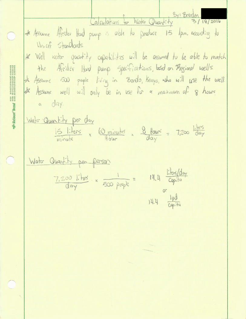

Appendix D
Hydrogeological Survey Report
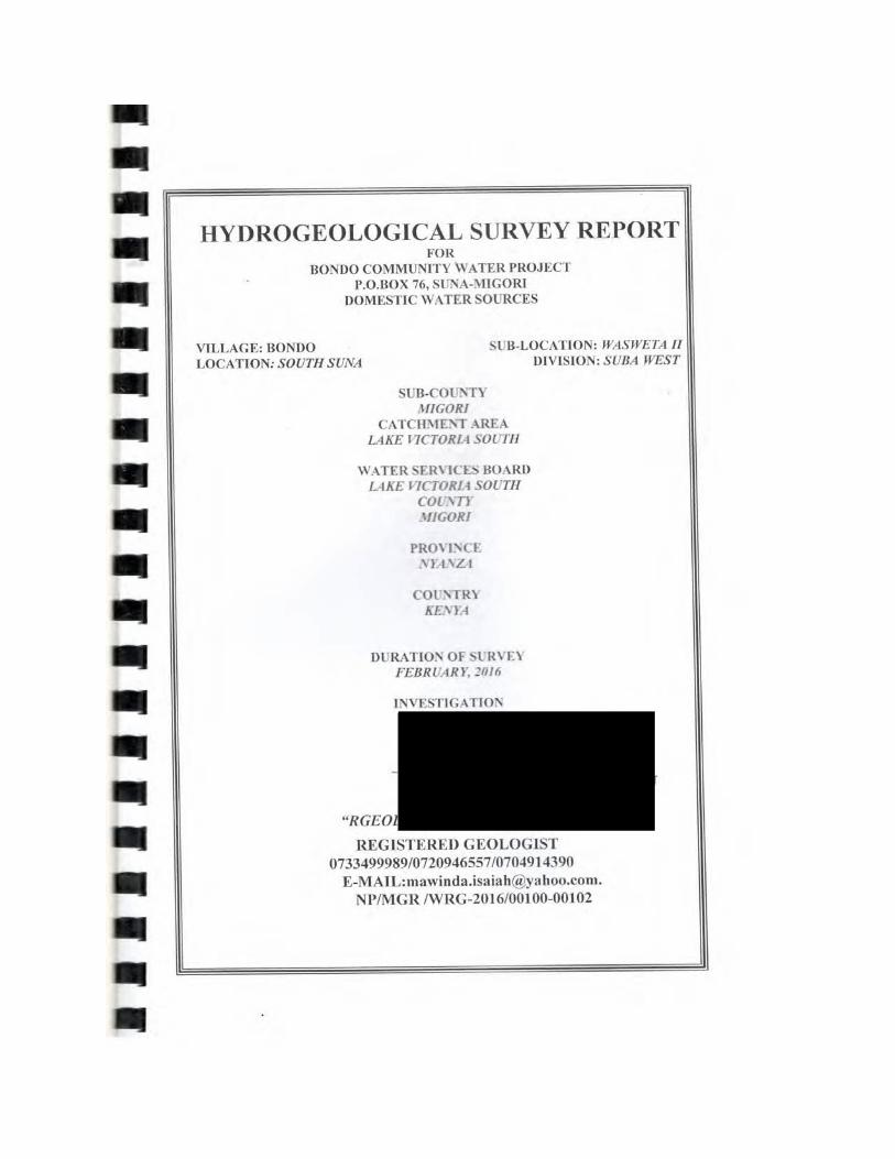
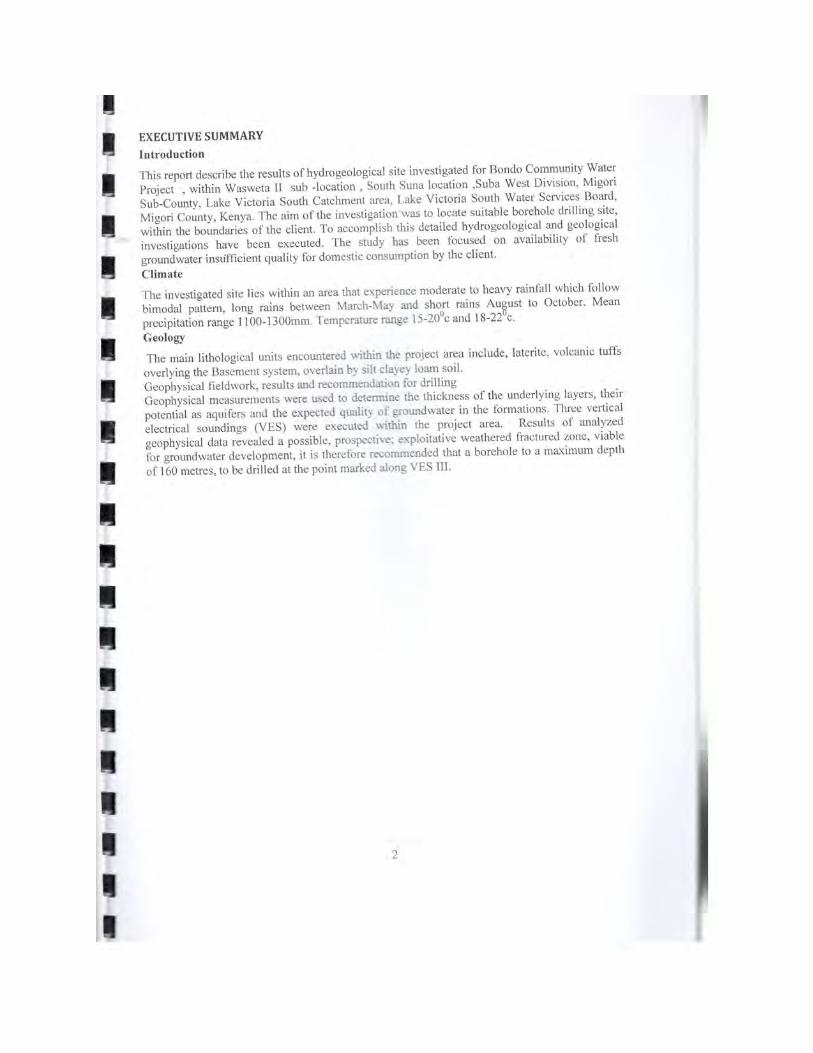
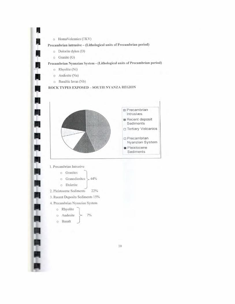
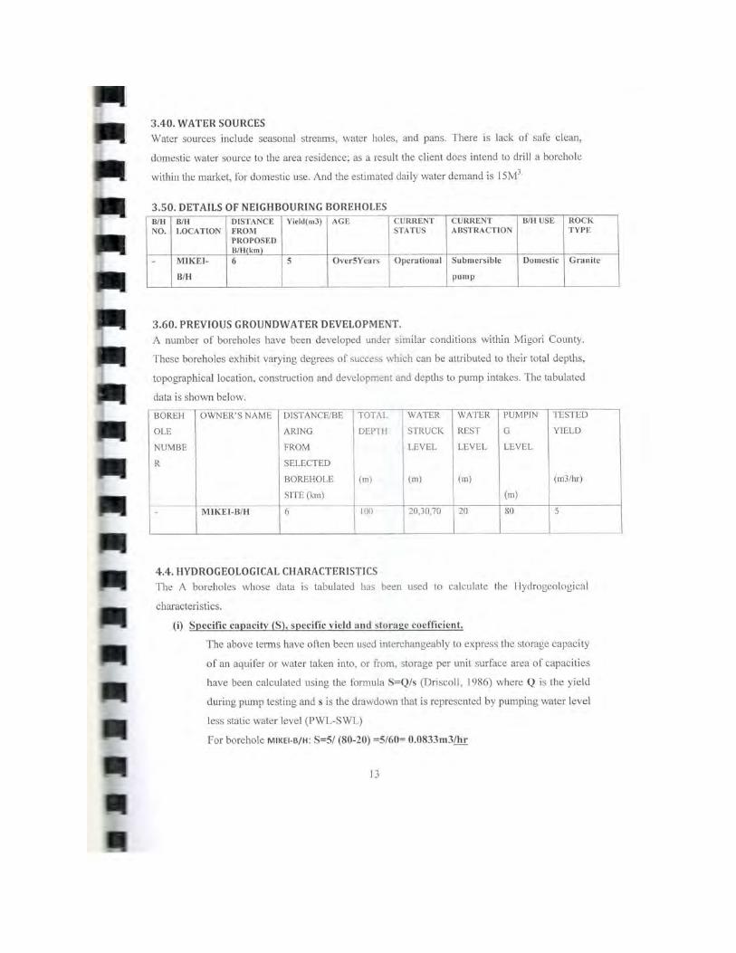
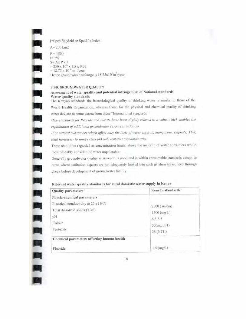
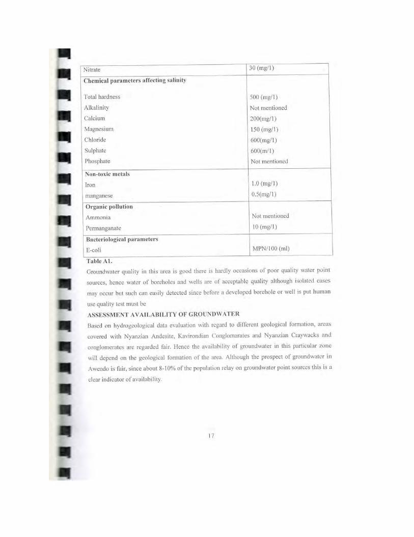
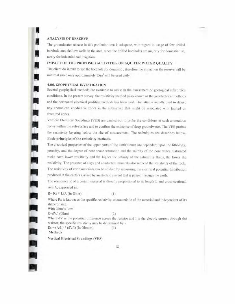
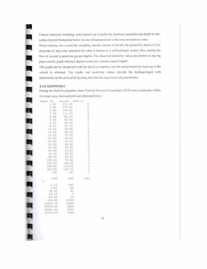
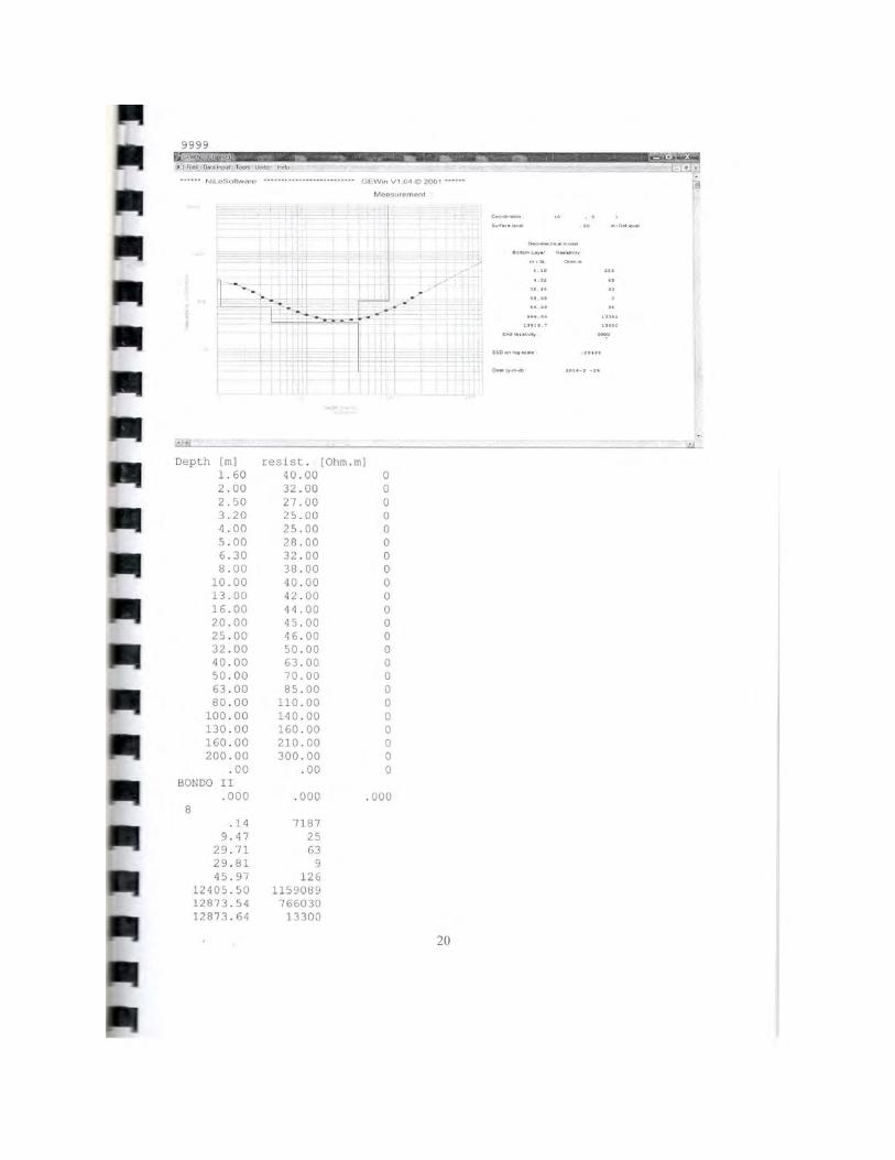
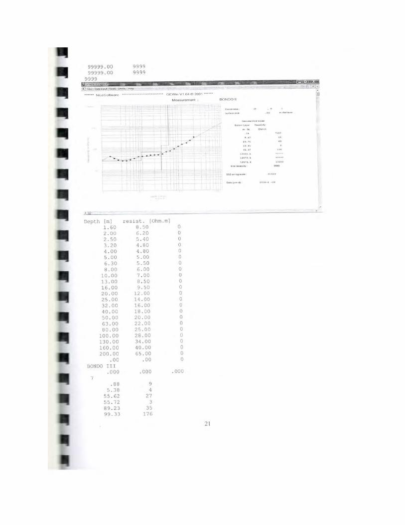
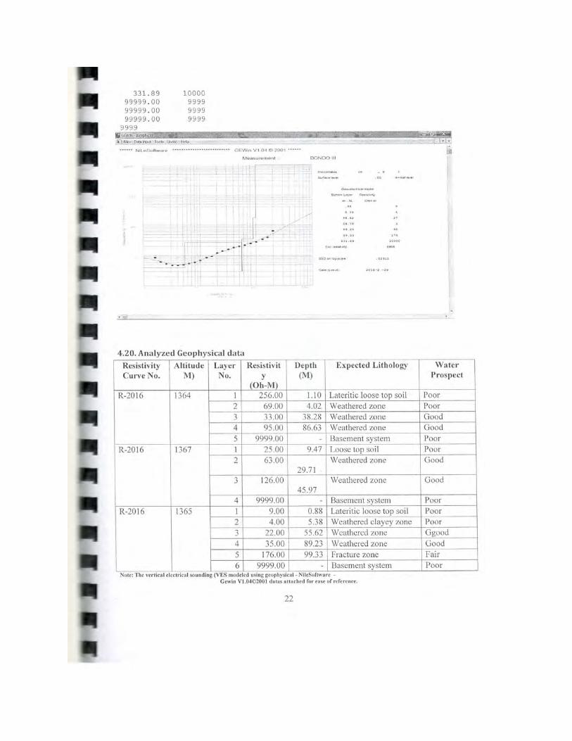

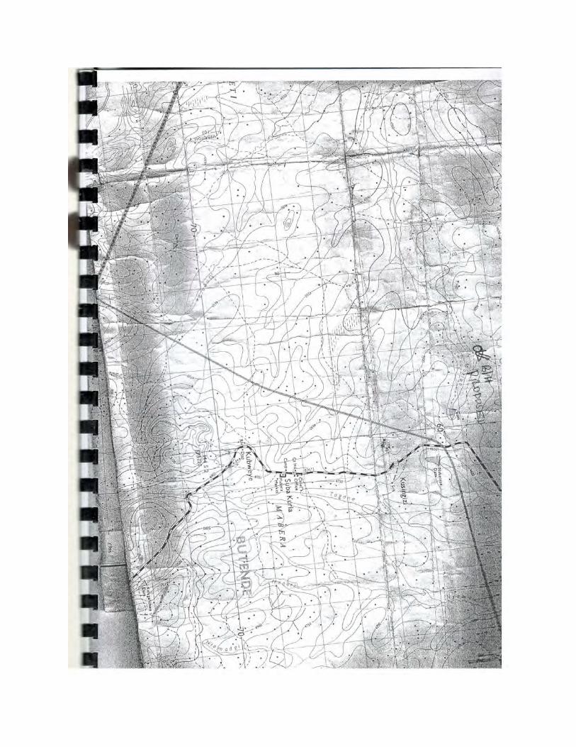
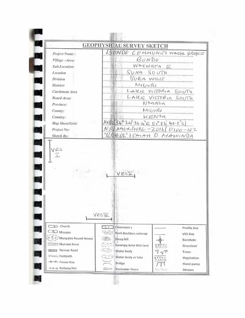
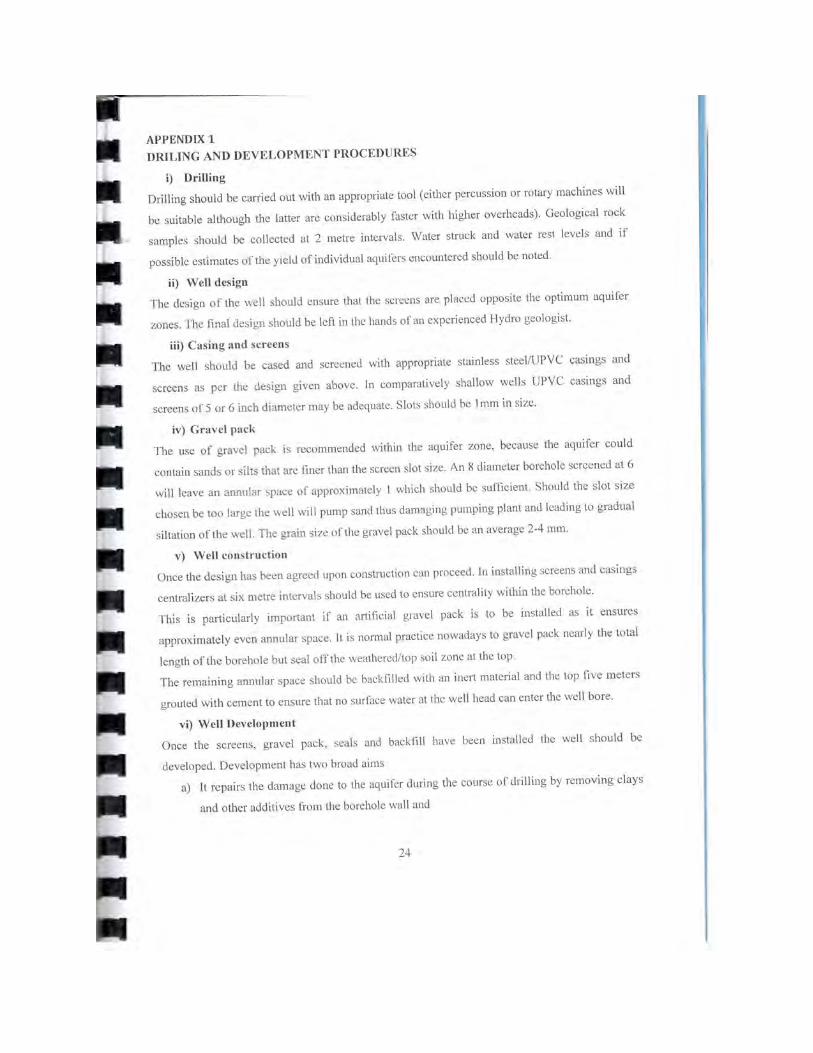
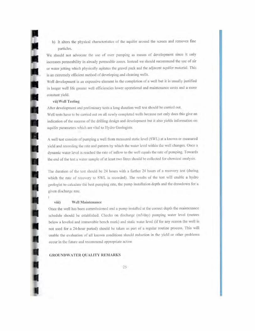
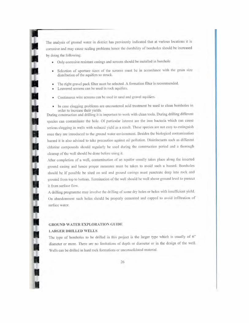
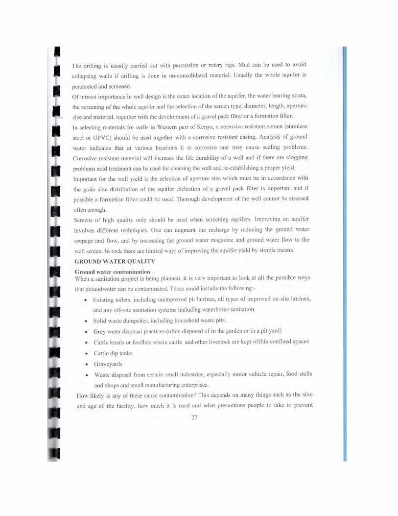
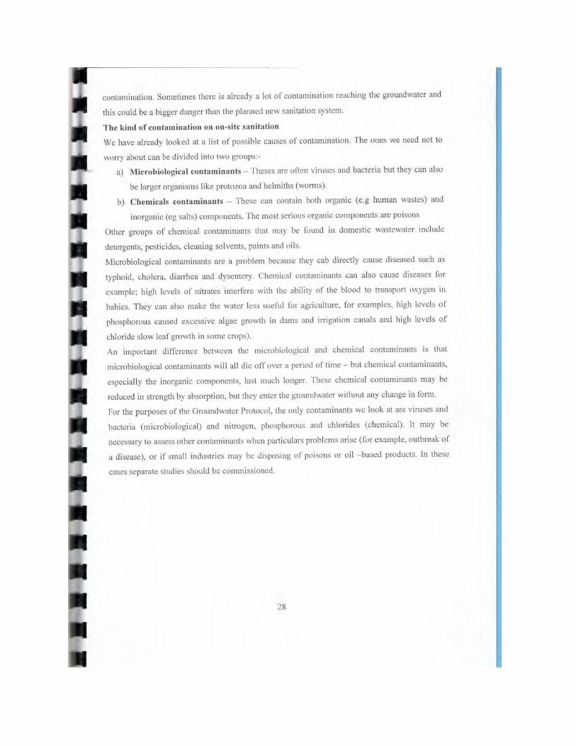

Appendix E
Pump Testing Procedures
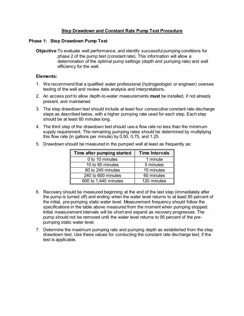
Step Drawdown and Constant Rate Pump Test Procedure
Phase 1: Step Drawdown Pump Test
Objective:To evaluate well performance, and identify successful pumping conditions for phase 2 of the pump test (constant rate). This information will allow a determination of the optimal pump settings (depth and pumping rate) and well efficiency for the well.
Elements:
1. We recommend that a qualified water professional (hydrogeologist or engineer) oversee testing of the well and review data analysis and interpretations.
2. An access port to allow depth-to-water measurements must be installed, if not already present, and maintained.
3. The step drawdown test should include at least four consecutive constant rate discharge steps as described below, with a higher pumping rate used for each step. Each step should be at least 60 minutes long.
4. The third step of the drawdown test should use a flow rate no less than the minimum supply requirement. The remaining pumping rates should be determined by multiplying this flow rate (in gallons per minute) by 0.50, 0.75, and 1.25.
5. Drawdown should be measured in the pumped well at least as frequently as:
Time after pumping started Time Intervals 0 to 10 minutes 1 minute 10 to 60 minutes 5 minutes 60 to 240 minutes 15 minutes 240 to 600 minutes 60 minutes
600 to 1,440 minutes 120 minutes
6. Recovery should be measured beginning at the end of the last step (immediately after the pump is turned off) and ending when the water level returns to at least 95 percent of the initial, pre-pumping static water level. Measurement frequency should follow the specifications in the table above measured from the moment when pumping stopped. Initial measurement intervals will be short and expand as recovery progresses. The pump should not be removed until the water level returns to 95 percent of the pre-pumping static water level.
7. Determine the maximum pumping rate and pumping depth as established from the step drawdown test. Use these values for conducting the constant rate discharge test, if the test is applicable.

Phase 2: Constant Rate Pump Test
Objective: To determine the capacity of the well and aquifer to provide a reliable yield of water at the desired rate. The pumping and recovery data from the test can be used to estimate aquifer transmissivity and a sustainable yield for the well. This test procedure is recommended for sources in complex hydrologic settings where the nature of the aquifer could adversely affect long-term continuous use of the source.
Elements: 1. We recommend that a qualified water professional (hydrogeologist or engineer) oversee
testing of the well. 2. An access port to allow depth to water measurements must be installed, if not already
present, and maintained.
3. The source should be pump tested at no less than the maximum rate determined from the step drawdown test. The constant rate discharge test should not be conducted until after the water levels in the aquifer have achieved at least 95 percent recovery from the step drawdown test pre-pumping static water level conditions.
4. The constant rate discharge test should be at least 24 hours long. If, at 24 hours, four hours of stabilized drawdown have been observed, the pump may be shut off and measurements of recovery begun. If stabilized drawdown has not been observed within a total of 36 hours, the pump may be shut off and recovery measurements begun. Stabilization is defined as a drop in water level of less than or equal to 0.1 feet per hour.
5. Drawdown should be measured in the pumped well at least as frequently as:
Time after pumping started Time intervals 0 to 10 minutes 1 minute 10 to 60 minutes 5 minutes 60 to 240 minutes 30 minutes 240 to 600 minutes 60 minutes
600 to 1440 minutes 120 minutes
6. Water samples must be collected from the source using proper sampling procedures and analyzed by a certified laboratory. Water samples must be taken within the last 15 minutes of pumping and analyzed for the following water quality parameters: - Coliform (bacteria)
- Inorganic Chemicals (IOCs)
- Additional Volatile and/or Synthetic Organic Chemicals (VOCs /SOCs)
7. After pumping, recovery data should be collected until 95 percent recovery of the pre-pumping static water level is achieved. Recovery should be measured in the same manner and at the same frequency as the table above. To facilitate accurate recovery data collection, the pump test piping should incorporate backflow check-valve(s) that prevent water within the riser pipe from flowing back into the well when the pump is shut off.
8. When the pumping test is completed, the data should be compiled into a report. The report should include:
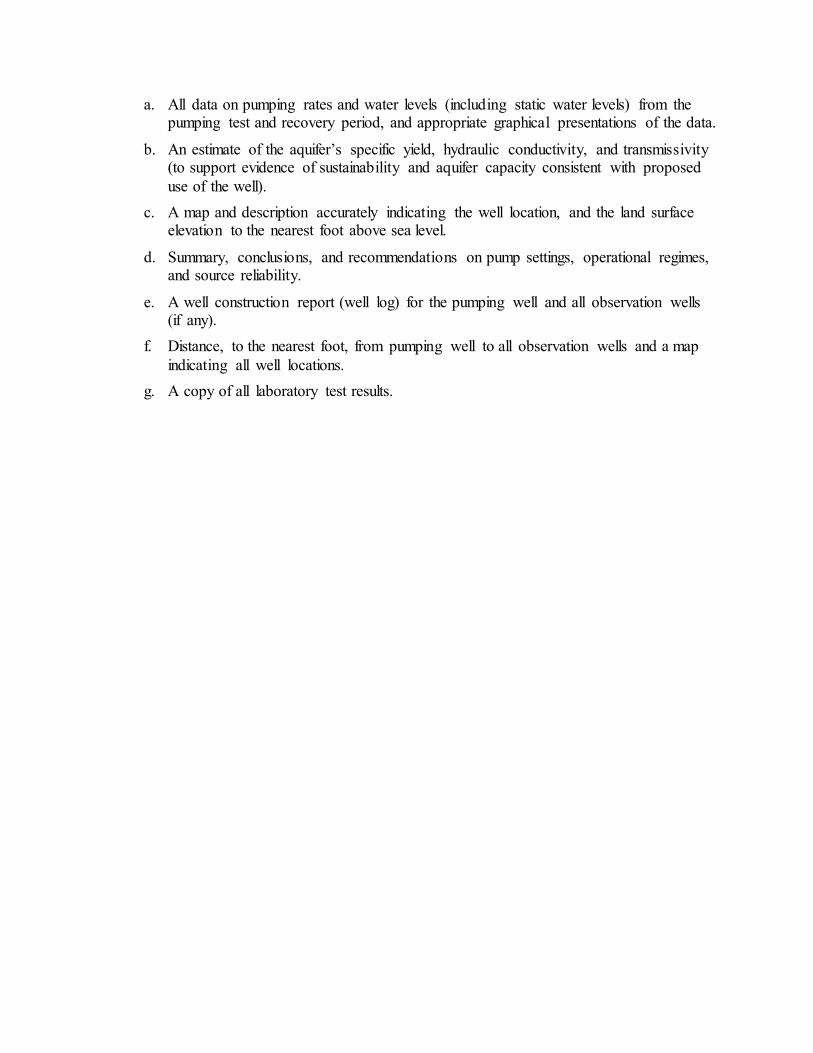
a. All data on pumping rates and water levels (including static water levels) from the pumping test and recovery period, and appropriate graphical presentations of the data.
b. An estimate of the aquifer’s specific yield, hydraulic conductivity, and transmissivity (to support evidence of sustainability and aquifer capacity consistent with proposed use of the well).
c. A map and description accurately indicating the well location, and the land surface elevation to the nearest foot above sea level.
d. Summary, conclusions, and recommendations on pump settings, operational regimes, and source reliability.
e. A well construction report (well log) for the pumping well and all observation wells (if any).
f. Distance, to the nearest foot, from pumping well to all observation wells and a map indicating all well locations.
g. A copy of all laboratory test results.
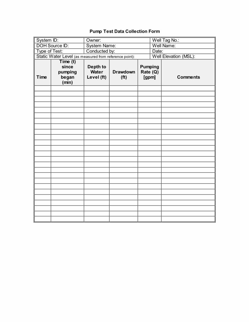
Pump Test Data Collection Form
System ID: Owner: Well Tag No.: DOH Source ID: System Name: Well Name: Type of Test: Conducted by: Date: Static Water Level (as measured from reference point): Well Elevation (MSL): Time
Time (t) since
pumping began (min)
Depth to
Water Level (ft)
Drawdown (ft)
Pumping Rate (Q)
[gpm]
Comments
Recovery Data Collection Form
System ID: Owner: Well Tag No.: DOH Source ID: System Name: Well Name: Type of Test: Conducted By: Date: Static Water Level (as measured from reference point): Well Elevation (MSL): Time
Time (t) since
pumping began (min)
Time (t’) since
pumping stopped
(min))
Depth to
Water Level
(ft)
Residual
Drawdown (ft)
Comments

Appendix F
Operation and Maintenance Manual
Bondo, Kenya
Well and Pump Maintenance Manual
EWB – Hope College March 2016
Adam Michelle
2
Contents 1.0 System background ....................................................................................................... 3
2.0 Contact List ................................................................................................................... 3
3.0 Maintenance of Well Enclosure .................................................................................... 3
4.0 Maintenance of Well Pad .............................................................................................. 3
5.0 Maintenance of Hand Pump .......................................................................................... 4
5.1 Preventative Maintenance ......................................................................................... 4
5.1.1 Weekly Checks .................................................................................................. 4
5.1.2 Monthly Checks ................................................................................................. 4
5.1.3 Leakage Test ...................................................................................................... 4
5.1.4 Discharge Test ................................................................................................... 5
5.2 Maintenance of Hand Pump ...................................................................................... 5
5.2.1 Diagnosis of Hand Pump Problems ................................................................... 5
5.2.2 Tools and Spare Parts Required for Hand Pump Maintenance .......................... 5
5.2.3 Hand Pump Maintenance and Repair Procedures .............................................. 5
Appendix Appendix A – Pump Troubleshooting Guide, Pump Maintenance Card, Parts List Appendix B – Afridev Pump Manual Appendix C – Well Construction Drawings
3
1.0 System background The proper maintenance of a well system consisting of the well enclosure, the well pad, and the hand pump, is an important aspect of maintaining the longevity of the well. The well enclosure, constructed from barbed wire and wood posts, is designed to prevent animals from accessing the well. The well pad, constructed of concrete and gravel, is designed to prevent contamination of the water source due to stagnant water collecting near the well pump. The hand pump, consisting of the pump head, pump stand, rinsing main, cylinder, and pump rod, is designed to draw water up from the ground water table. The proper maintenance procedures of the components listed above is outlined in the following sections. 2.0 Contact List
Mr. (Pump Mechanic) Email: Phone: EWB-Hope College Email: [email protected]
3.0 Maintenance of Well Enclosure The maintenance of the well enclosure plays an important role in the prevention of water contamination due to animals getting near the well. In order to prevent animals from contaminating the water source, the caretaker should:
Make sure the posts are stable and firmly planted in the ground Check and repair holes in the enclosure fencing
Materials required to make repairs can be found in the market place of Bondo or in Migouri.
4.0 Maintenance of Well Pad Even when hand pumps are fitted, contaminations can still pollute the well through:
Cracked platforms and drainage channel Stagnant water near the well Animal and human excrement too close to the well Waste and other sources of contamination too close to the well
It is important for the caretaker to:
Check the platform for cracks and do the necessary repair Eliminate stagnant water by filling dents and holes on the well pad platform with
concrete grout Keep the areas surrounding the well pad clean and tidy at all times
4
Materials required to make repairs can be found in the market place of Bondo or in Migouri.
5.0 Maintenance of Hand Pump Basic hand pump checks and maintenance are provided in the following sections. Additionally, a pump troubleshooting guide, maintenance card, and repair parts list are provided in Appendix A, the full pump manual is provided in Appendix B.
5.1 Preventative Maintenance
Preventative maintenance consists of checking the hand pump at regular intervals and changing parts showing signs of wear before they are fully worn out or broken. These checks help to increase the longevity of the well and can be broken down into weekly and monthly checks. 5.1.1 Weekly Checks Weekly checks include:
Checking that the flange bolts and nuts are tight on the pump stand Checking that the fulcrum pin nuts and hanger pin nuts are tight
5.1.2 Monthly Checks Monthly checks include:
Checking if any fasteners or parts of the pump are missing. If so, replace the part. Checking if there are any unusual noises and taking corrective action Checking if the pump stand is shaky during operation. If yes, the stand is loose at
the foundation and contamination of the well could take place. Take corrective measures to repair the well.
Check if there is leakage in the pump. If more than 5 strokes are required before water comes out from the spout, it means the pump is leaking beyond the acceptable limit.
Carry out a “Leakage and Discharge Test” per the directions provided in the following sections, 3.1.3 and 3.1.4.
5.1.3 Leakage Test Proceed as follows:
Operate the pump handle until water is flowing from the spout Stop operating the pump handle for approximately 30 minutes Then operate the handle and count how many strokes required until the water is
starting to flow again. If more than 5 full handle strokes are required to make the water flow again, there must be a leakage in the rising main or the foot-valve. Leakage mostly occurs because of a
5
warn bobbin or O-ring in the foot-valve, disconnected rising main joints, or perforated or cracked riser pipes. Report this problem immediately to the pump mechanic (see section 2.0)
5.1.4 Discharge Test Proceed as follows:
Operate the pump handle until a continuous water flow has been achieved (pump ratio approximately 40 full strokes per minute)
Place a bucket in the continuous water flow for exactly one minute. Take the bucket off the water flow and check the amount of water drawn.
The water collected should not be less than 15 liters. If the discharge is less than 10 liters for 40 full strokes, there might be a problem with the bobbins or the cup seal. Report this problem immediately to the pump mechanic (see section 2.0).
5.2 Maintenance of Hand Pump Without proper preventative maintenance, sudden breakdown of hand pumps and disruption in the water supply could occur. However, if maintenance is necessary, the care taker should:
Understand the cause for the problem and determine the necessary repair Dismantle the pump, if necessary Reassemble the pump after replacing defective components Record details on the “Maintenance card” (see Appendix A)
5.2.1 Diagnosis of Hand Pump Problems
To identify the cause for a problem and remedy needed, please refer to the “Trouble Shooting Chart” (see Appendix A). This chart lists general operational problems, their causes and remedies.
5.2.2 Tools and Spare Parts Required for Hand Pump Maintenance The basic tools required for hand pump maintenance are:
Spanner for M16 hexagonal bolts and nuts Fishing tool for retrieving the foot-valve For deep installations (between 30 to 45 m) with a heavy load of the pump rod
assembly, the use of a Resting tool & Connecting tool is advisable (this is for threaded rods only).
The “List of Spare Parts for AFRIDEV Handpumps” is given in Appendix A. See also “Replacement Interval of AFRIDEV Wearing Parts” (Appendix B). 5.2.3 Hand Pump Maintenance and Repair Procedures
6
If dismantling and reassembling the hand pump is necessary for proper maintenance and repair, please refer to the “Installation and Maintenance Manual for the Afridev Handpump” given in Appendix B. The maintenance procedure for
Dismantling “above ground components” can be found on page 47 Dismantling threaded pump rods can be found on page 48 Reinstalling threaded pump rods can be found on page 48 Dismantling hook and eye pump rods can be found on page 49 Reinstalling hook and eye pump rods can be found on page 49 Dismantling and reinstalling FRP pump rods can be found on page 50 Reassembling “above ground components” can be found on page 50
The repair procedure for
Removal of the rising main can be found on page 51 Repair of the rinsing main pipe can be found on page 53 Fishing of dropped hand pump parts can be found on page 55
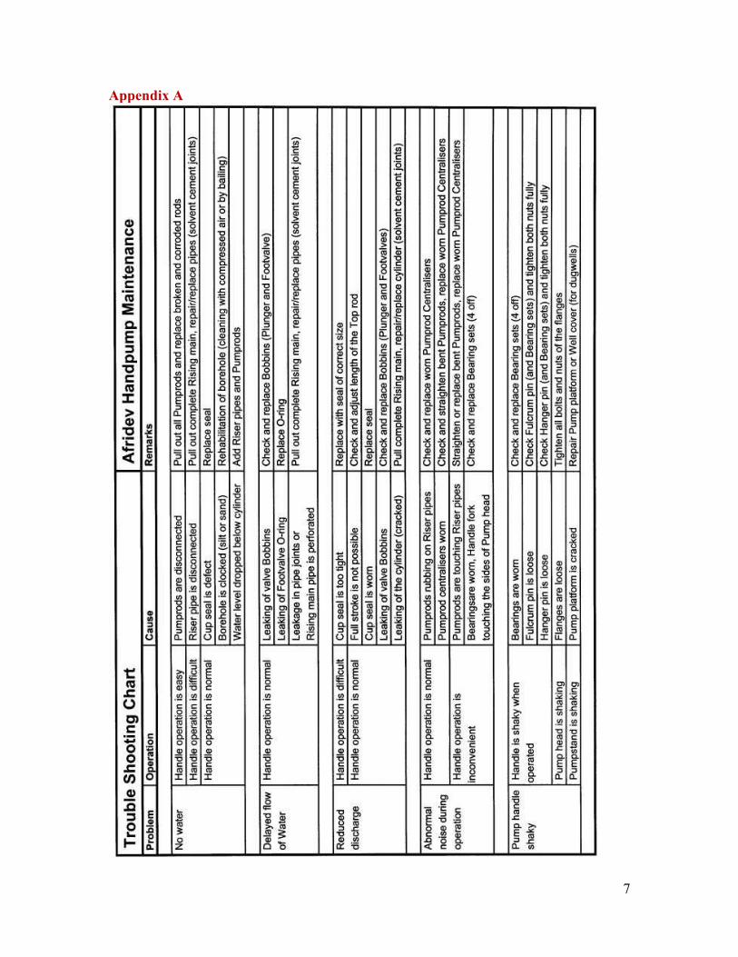
7
Appendix A
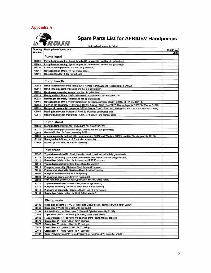
8
Appendix A
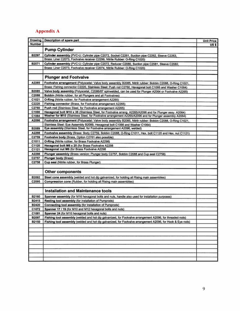
9
Appendix A
10
Appendix A
1
Installation and Maintenance Manual for the Afridev Handpump
REVISION 2 - 2007 This manual has been prepared to cover installation and maintenance aspects of the Afridev Handpump. This document results from several years of work carried out by Water & Sanitation Program (WSP) in partnership with SKAT – RWSN (former HTN), NGO’s, handpump field workers and the private sector in several countries. The experience gained in recent years has been incorporated into this Specification. This Manual is intended to assist all users of the Afridev Handpump, especially to give a guideline for the installation procedure and also for preventive maintenance. Suggestions for improvements and requests for further information are welcome, and should be sent to SKAT at the address given below. First edition: SKAT - HTN Publication, 1995 Revised edition: 2-2007 by Karl Erpf, Drawings: SKAT, St.Gallen, Photographs: Meera & Ceiko Pumps Ltd. Hyderabad, India, and SKAT, St.Gallen, Copyright: SKAT - RWSN
Provided the source SKAT - RWSN is acknowledged, extracts of this publication may be reproduced.
Distribution: SKAT Vadianstrasse 42 CH-9000 St.Gallen Switzerland Phone: +41 71 228 54 54 Fax: +41 71 228 54 55 E-mail: [email protected] or [email protected] URL: http://www.skat.ch and http://www.rwsn.ch
2
Installation and Maintenance Manual for the Afridev Handpump
Contents Page No.
1.0 Background of the Afridev Handpump Development ...........…………………….. 4 2.0 Pump Features and Options .........................................................……………….. 4 3.0 Supporting Documents .........................................................………………………. 9 Part 1 Installation of the Afridev Handpump 4.0 Platform Construction ........................................................………………………. 10
4.1 General Comments ........................................................…………………….. 10
4.2 Selection of Platform Type .............................................…………………….. 12
4.3 Material required for Platform Construction ......................…………………… 17
4.4 Preparation for Grouting the Platform for a Borehole ..........………………… 18
4.5 Grouting the Platform ........................................................…………….……. 20
4.6 Curing of Platform ........................................................…………………….. 23
4.7 Hard Core Layer and Fencing of Platform ......................……………………. 24
4.8 Soak pit ....................................................................………………………… 24
4.9 Disinfecting the Well ........................................................……………………. 25 5.0 Preparation for Handpump Installation .................................………………….. 26
5.1 Decision on correct Cylinder Setting Depth ......................……………………. 26
5.2 Materials and Tools required for Installation of “Down Hole Components” ….. 28
5.3 Preparation of “Down Hole Components” ......................……………………… 28
5.4 Important Information for Jointing PVC-U Pipes ...........……………………… 31
5.5 Preparation of “Above Ground Components” ......................…………………. 32 6.0 Handpump Installation Sequences .............................................………………… 33
6.1 Installation of “Down Hole Components” ......................……………………….. 33
6.2 Installation of “Above Ground Components” ......................………………….. 38
3
Part 2 Maintenance of the Afridev Handpump 7.0 Preventive Maintenance ........................................................……………………. 45
7.1 Preventive Maintenance Checks of Handpump ......................………………. 45
7.2 Maintenance of Pump Surrounding .................................……………………. 46 8.0 Maintenance of Handpump .........................................................……………….. 47
8.1 Diagnosis of Handpump Problems ..................................…………………… 47
8.2 Tools and Spare Parts required for Handpump Maintenance ...........……….. 47
8.3 Procedure of Dismantling “Above Ground Components” ...........…………….. 47
8.4 Dismantling Threaded Pumprods ..................................…………………….. 48
8.5 Re-installing Threaded Pumprods ..................................…………………….. 48
8.6 Dismantling Hook & Eye Pumprods ..................................…………………… 49
8.7 Re-installing Hook & Eye Pumprods ..................................…………………. 49
8.8 Dismantling and Re-installing FRP Pumprods .......................……………….. 50
8.9 Re-assembling “Above Ground Components” .......................……………….. 50 9.0 Repair of Handpump .....................................................................……………….. 51
9.1 Removal of the Rising main ..............................................…………………… 51
9.2 Repair of the Rising main pipe ..............................................……………….. 53
9.3 Fishing of Dropped Handpump Parts ..................................…………………. 55 10.0 Recording of Interventions .....................................................………….……….. 55 Annexes:
I Trouble Shooting Chart for AFRIDEV Handpumps ……………………………. 56
II List of Spare Parts for AFRIDEV Handpumps ………………………………… 58
III Replacement Interval of AFRIDEV Wearing Parts …………………………… 61
IV Correct Storage of AFRIDEV Handpump Components ……………………… 63
V Examples for Recording of Interventions ……………………………………… 66
VI Drawings of Fishing Tools for dropped Handpump Parts …………………….. 70
VII Technical Drawings of Repair Sockets …………………………………………. 74
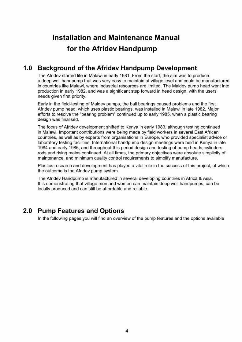
4
Installation and Maintenance Manual for the Afridev Handpump
1.0 Background of the Afridev Handpump Development
The Afridev started life in Malawi in early 1981. From the start, the aim was to produce a deep well handpump that was very easy to maintain at village level and could be manufactured in countries like Malawi, where industrial resources are limited. The Maldev pump head went into production in early 1982, and was a significant step forward in head design, with the users' needs given first priority.
Early in the field-testing of Maldev pumps, the ball bearings caused problems and the first Afridev pump head, which uses plastic bearings, was installed in Malawi in late 1982. Major efforts to resolve the "bearing problem" continued up to early 1985, when a plastic bearing design was finalised.
The focus of Afridev development shifted to Kenya in early 1983, although testing continued in Malawi. Important contributions were being made by field workers in several East African countries, as well as by experts from organisations in Europe, who provided specialist advice or laboratory testing facilities. International handpump design meetings were held in Kenya in late 1984 and early 1986, and throughout this period design and testing of pump heads, cylinders, rods and rising mains continued. At all times, the primary objectives were absolute simplicity of maintenance, and minimum quality control requirements to simplify manufacture.
Plastics research and development has played a vital role in the success of this project, of which the outcome is the Afridev pump system.
The Afridev Handpump is manufactured in several developing countries in Africa & Asia. It is demonstrating that village men and women can maintain deep well handpumps, can be locally produced and can still be affordable and reliable.
2.0 Pump Features and Options
In the following pages you will find an overview of the pump features and the options available
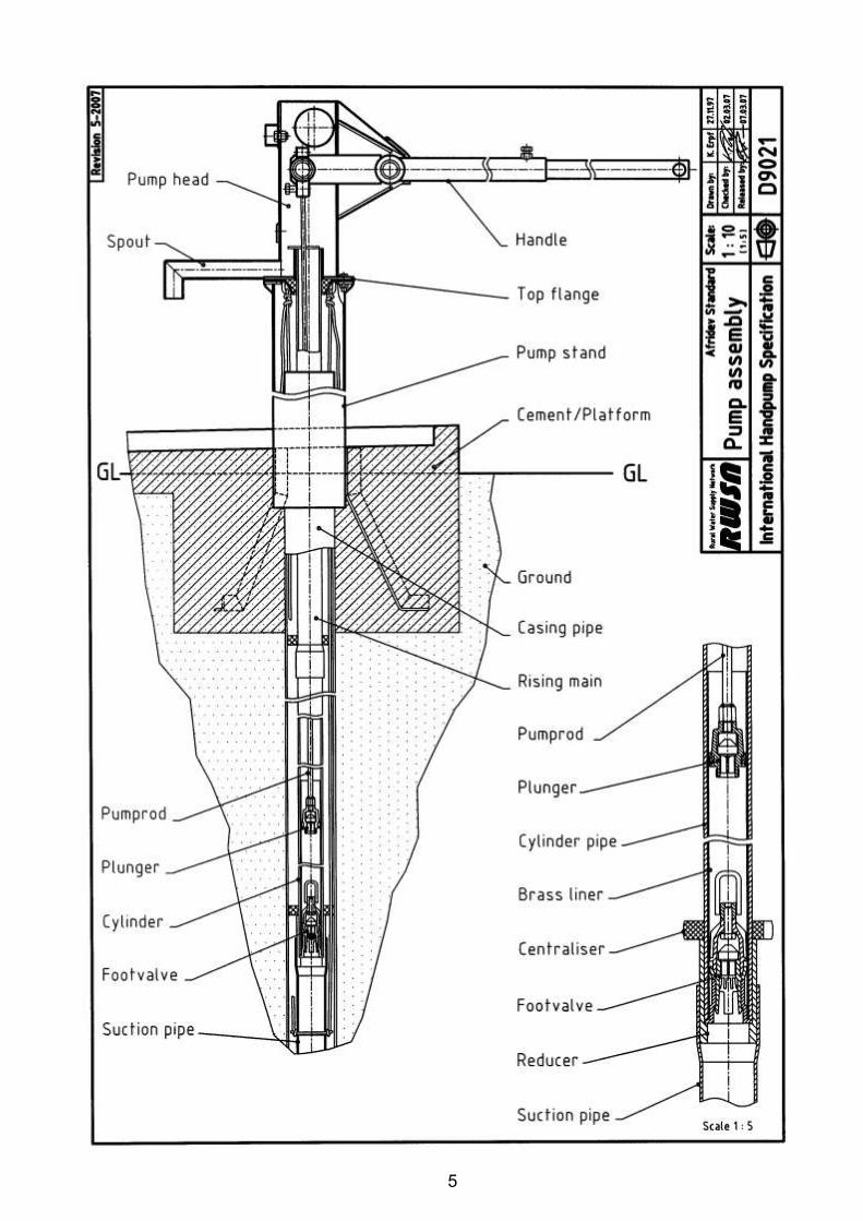
5
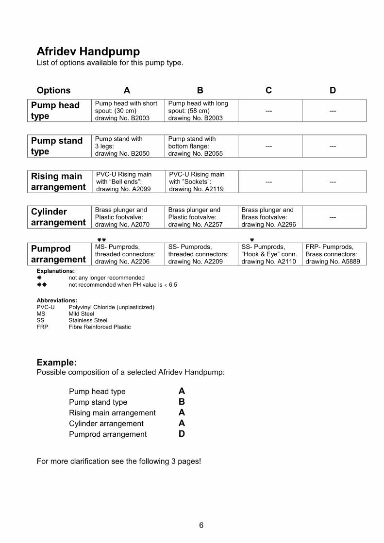
6
Afridev Handpump List of options available for this pump type. Options A B C D
Pump head type
Pump head with short spout: (30 cm) drawing No. B2003
Pump head with long spout: (58 cm) drawing No. B2003
---
---
Pump stand type
Pump stand with 3 legs: drawing No. B2050
Pump stand with bottom flange: drawing No. B2055
---
---
Rising main arrangement
PVC-U Rising main with “Bell ends”: drawing No. A2099
PVC-U Rising main with ”Sockets”: drawing No. A2119
---
---
Cylinder arrangement
Brass plunger and Plastic footvalve: drawing No. A2070
Brass plunger and Plastic footvalve: drawing No. A2257
Brass plunger and Brass footvalve: drawing No. A2296
---
Pumprod arrangement
MS- Pumprods, threaded connectors: drawing No. A2206
SS- Pumprods, threaded connectors: drawing No. A2209
SS- Pumprods, “Hook & Eye” conn. drawing No. A2110
FRP- Pumprods, Brass connectors: drawing No. A5889
Explanations: not any longer recommended not recommended when PH value is 6.5 Abbreviations: PVC-U Polyvinyl Chloride (unplasticized) MS Mild Steel SS Stainless Steel FRP Fibre Reinforced Plastic Example: Possible composition of a selected Afridev Handpump:
Pump head type A Pump stand type B Rising main arrangement A Cylinder arrangement A Pumprod arrangement D
For more clarification see the following 3 pages!
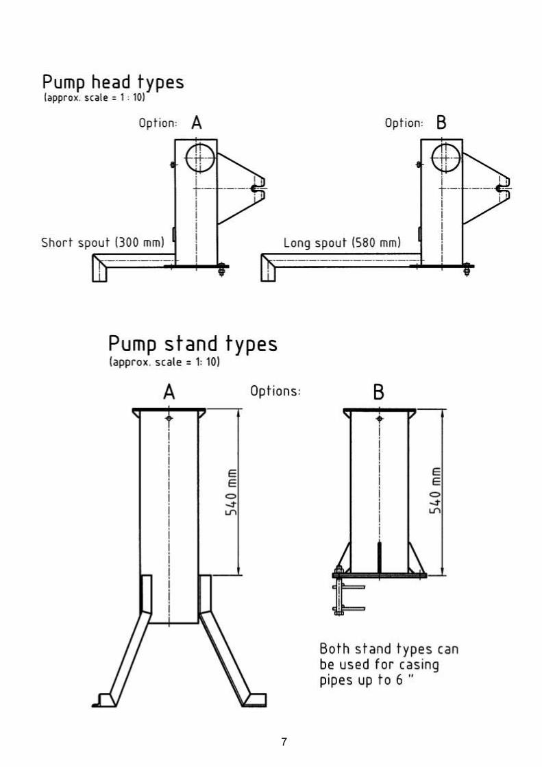
7
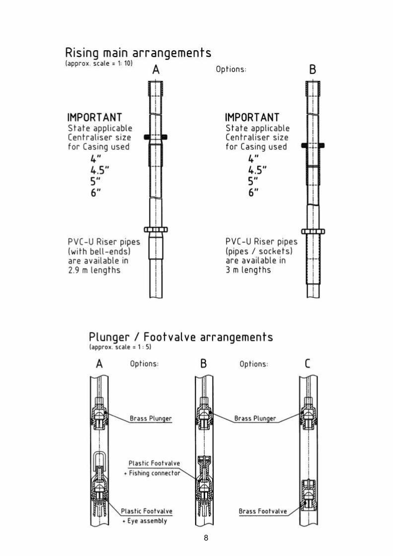
8

9
3.0 Supporting Documents
a) Afridev Handpump Specification, Revision 5-2007, b) Afridev Handpump, Injection Moulding Guidelines, Revision 1-1999, c) Moulding Guidelines for the Production of Rubber Components, Revision 1-1999, d) Afridev Handpump, Mould Drawings for Rubber Components, Edition 2003, e) Afridev Handpump, Packing Guidelines, Edition 1992, f) Afridev Handpump, Quality Control Guidelines, Revision 1-2000, g) Platform Design for Handpumps on Boreholes (Construction Guide), Rev. 1-2008, h) Platform Design for Handpumps on Dug wells (Construction Guide), Rev. 1-2008,

10
Part 1 Installation of the Afridev Handpump 4.0 Platform Construction 4.1 General Comments
Sustained safe drinking water supply and sanitation facilities are essential to improve the living conditions of the rural population. The provision of safe water helps to combat water borne diseases and improves community health in general. Benefits of a safe water supply can reach far beyond considerations of public health and have a positive influence on the general well being, economic status and quality of life in a community.
4.1.1 Protection of Water Source
If a well site is chosen and the well drilled (or dug) into the ground at a site which is elevated and away from water logged areas during the rainy season, the water which percolates from an underground aquifer into the well should be pure enough to drink. However, a water point obviously attracts a great deal of human contact. This is a potential source of contamination and should be protected against. The safety measures are as follows:
4.1.2 Well Siting
a) The well should be in an elevated place, so that during the rainy season the water will run away from it, rather than into it.
b) It should be at least 40 meters away from a latrine and uphill of the latrine. c) It should be at least 30 meters away from a cattle kraal, and uphill of the kraal. d) It should be well away from any depressed area in the ground, such as hollows that are used
for rubbish tipping, hollows that are used for brick making or any other areas where water might collect.
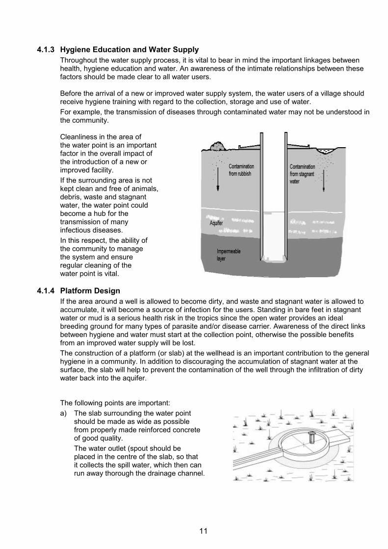
11
4.1.3 Hygiene Education and Water Supply
Throughout the water supply process, it is vital to bear in mind the important linkages between health, hygiene education and water. An awareness of the intimate relationships between these factors should be made clear to all water users.
Before the arrival of a new or improved water supply system, the water users of a village should receive hygiene training with regard to the collection, storage and use of water. For example, the transmission of diseases through contaminated water may not be understood in the community.
Cleanliness in the area of the water point is an important factor in the overall impact of the introduction of a new or improved facility. If the surrounding area is not kept clean and free of animals, debris, waste and stagnant water, the water point could become a hub for the transmission of many infectious diseases. In this respect, the ability of the community to manage the system and ensure regular cleaning of the water point is vital.
4.1.4 Platform Design
If the area around a well is allowed to become dirty, and waste and stagnant water is allowed to accumulate, it will become a source of infection for the users. Standing in bare feet in stagnant water or mud is a serious health risk in the tropics since the open water provides an ideal breeding ground for many types of parasite and/or disease carrier. Awareness of the direct links between hygiene and water must start at the collection point, otherwise the possible benefits from an improved water supply will be lost. The construction of a platform (or slab) at the wellhead is an important contribution to the general hygiene in a community. In addition to discouraging the accumulation of stagnant water at the surface, the slab will help to prevent the contamination of the well through the infiltration of dirty water back into the aquifer.
The following points are important: a) The slab surrounding the water point
should be made as wide as possible from properly made reinforced concrete of good quality. The water outlet (spout should be placed in the centre of the slab, so that it collects the spill water, which then can run away thorough the drainage channel.
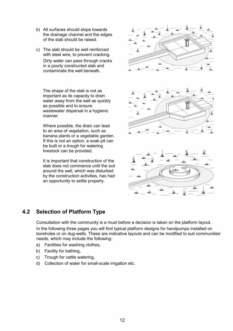
12
b) All surfaces should slope towards
the drainage channel and the edges of the slab should be raised.
c) The slab should be well reinforced
with steel wire, to prevent cracking. Dirty water can pass through cracks in a poorly constructed slab and contaminate the well beneath.
The shape of the slab is not as important as its capacity to drain water away from the well as quickly as possible and to ensure wastewater dispersal in a hygienic manner.
Where possible, the drain can lead to an area of vegetation, such as banana plants or a vegetable garden. If this is not an option, a soak-pit can be built or a trough for watering livestock can be provided.
It is important that construction of the slab does not commence until the soil around the well, which was disturbed by the construction activities, has had an opportunity to settle properly.
4.2 Selection of Platform Type
Consultation with the community is a must before a decision is taken on the platform layout. In the following three pages you will find typical platform designs for handpumps installed on boreholes or on dug-wells. These are indicative layouts and can be modified to suit communities’ needs, which may include the following: a) Facilities for washing clothes, b) Facility for bathing, c) Trough for cattle watering, d) Collection of water for small-scale irrigation etc.
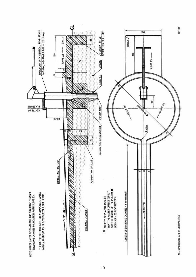
13
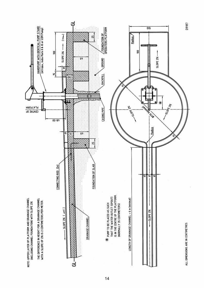
14
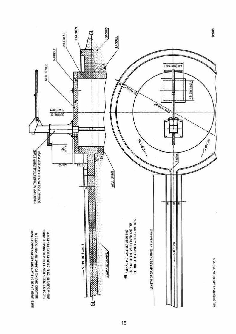
15
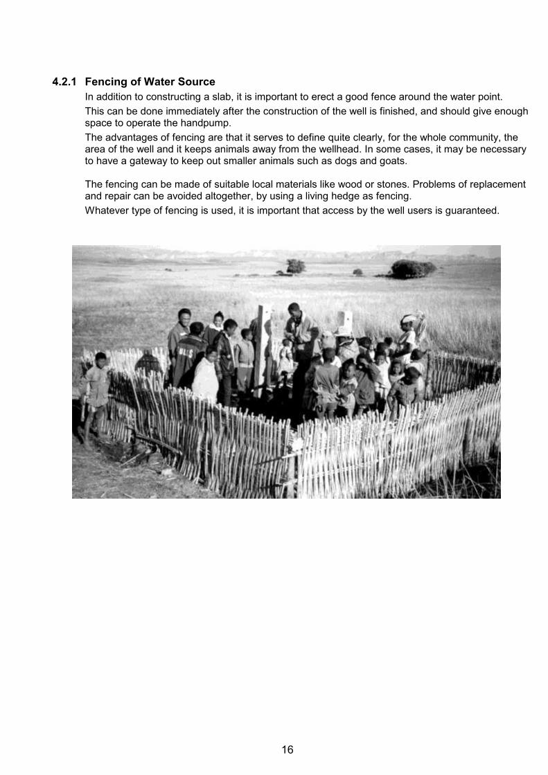
16
4.2.1 Fencing of Water Source
In addition to constructing a slab, it is important to erect a good fence around the water point. This can be done immediately after the construction of the well is finished, and should give enough space to operate the handpump. The advantages of fencing are that it serves to define quite clearly, for the whole community, the area of the well and it keeps animals away from the wellhead. In some cases, it may be necessary to have a gateway to keep out smaller animals such as dogs and goats.
The fencing can be made of suitable local materials like wood or stones. Problems of replacement and repair can be avoided altogether, by using a living hedge as fencing. Whatever type of fencing is used, it is important that access by the well users is guaranteed.
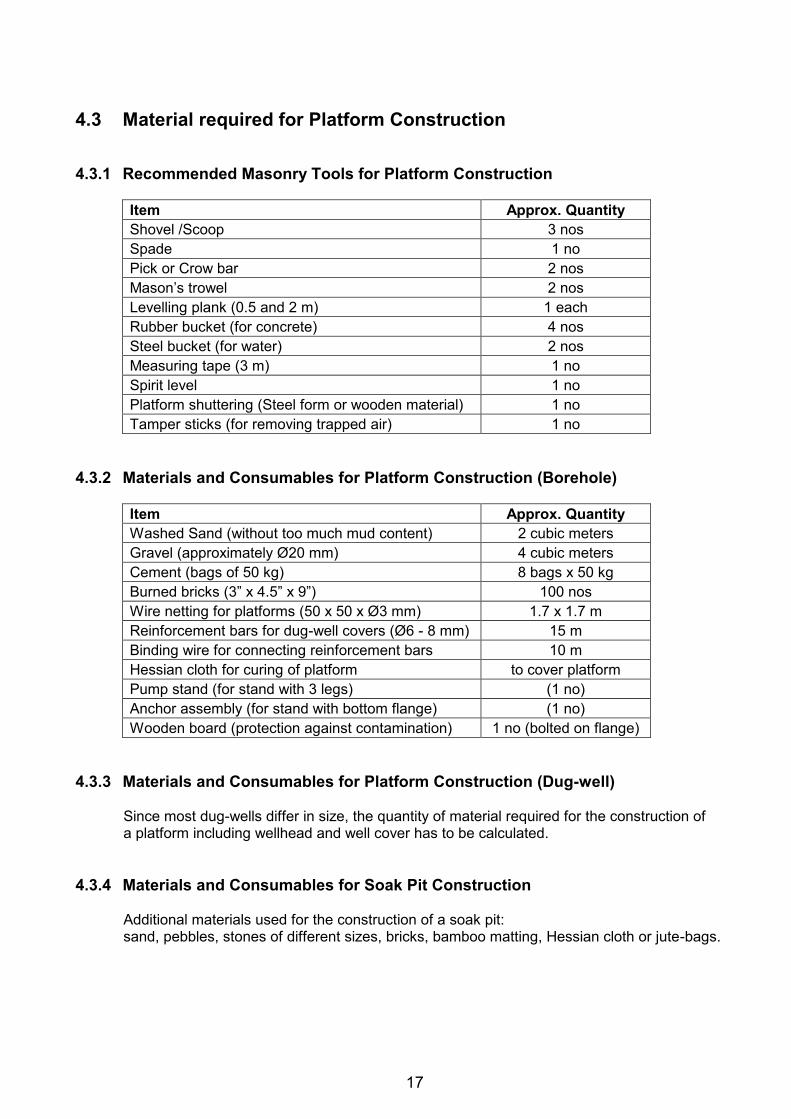
17
4.3 Material required for Platform Construction 4.3.1 Recommended Masonry Tools for Platform Construction
Item Approx. Quantity Shovel /Scoop 3 nos Spade 1 no Pick or Crow bar 2 nos Mason’s trowel 2 nos Levelling plank (0.5 and 2 m) 1 each Rubber bucket (for concrete) 4 nos Steel bucket (for water) 2 nos Measuring tape (3 m) 1 no Spirit level 1 no Platform shuttering (Steel form or wooden material) 1 no Tamper sticks (for removing trapped air) 1 no
4.3.2 Materials and Consumables for Platform Construction (Borehole)
Item Approx. Quantity Washed Sand (without too much mud content) 2 cubic meters Gravel (approximately Ø20 mm) 4 cubic meters Cement (bags of 50 kg) 8 bags x 50 kg Burned bricks (3” x 4.5” x 9”) 100 nos Wire netting for platforms (50 x 50 x Ø3 mm) 1.7 x 1.7 m Reinforcement bars for dug-well covers (Ø6 - 8 mm) 15 m Binding wire for connecting reinforcement bars 10 m Hessian cloth for curing of platform to cover platform Pump stand (for stand with 3 legs) (1 no) Anchor assembly (for stand with bottom flange) (1 no) Wooden board (protection against contamination) 1 no (bolted on flange)
4.3.3 Materials and Consumables for Platform Construction (Dug-well)
Since most dug-wells differ in size, the quantity of material required for the construction of a platform including wellhead and well cover has to be calculated.
4.3.4 Materials and Consumables for Soak Pit Construction
Additional materials used for the construction of a soak pit: sand, pebbles, stones of different sizes, bricks, bamboo matting, Hessian cloth or jute-bags.
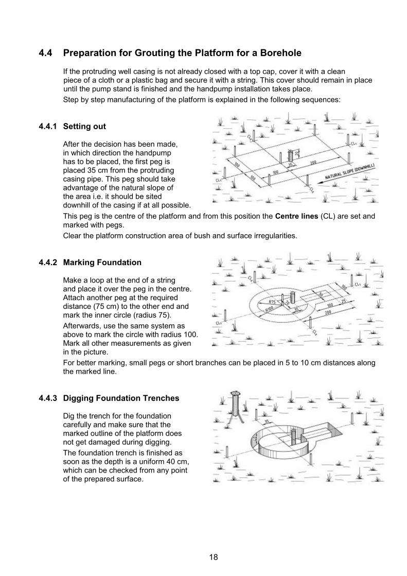
18
4.4 Preparation for Grouting the Platform for a Borehole
If the protruding well casing is not already closed with a top cap, cover it with a clean piece of a cloth or a plastic bag and secure it with a string. This cover should remain in place until the pump stand is finished and the handpump installation takes place. Step by step manufacturing of the platform is explained in the following sequences:
4.4.1 Setting out
After the decision has been made, in which direction the handpump has to be placed, the first peg is placed 35 cm from the protruding casing pipe. This peg should take advantage of the natural slope of the area i.e. it should be sited downhill of the casing if at all possible. This peg is the centre of the platform and from this position the Centre lines (CL) are set and marked with pegs. Clear the platform construction area of bush and surface irregularities.
4.4.2 Marking Foundation
Make a loop at the end of a string and place it over the peg in the centre. Attach another peg at the required distance (75 cm) to the other end and mark the inner circle (radius 75). Afterwards, use the same system as above to mark the circle with radius 100. Mark all other measurements as given in the picture. For better marking, small pegs or short branches can be placed in 5 to 10 cm distances along the marked line.
4.4.3 Digging Foundation Trenches
Dig the trench for the foundation carefully and make sure that the marked outline of the platform does not get damaged during digging. The foundation trench is finished as soon as the depth is a uniform 40 cm, which can be checked from any point of the prepared surface.
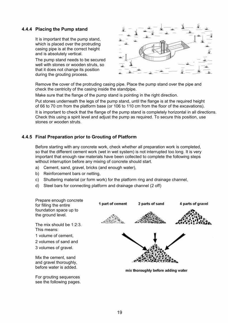
19
4.4.4 Placing the Pump stand
It is important that the pump stand, which is placed over the protruding casing pipe is at the correct height and is absolutely vertical. The pump stand needs to be secured well with stones or wooden struts, so that it does not change its position during the grouting process.
Remove the cover of the protruding casing pipe. Place the pump stand over the pipe and check the centricity of the casing inside the standpipe. Make sure that the flange of the pump stand is pointing in the right direction. Put stones underneath the legs of the pump stand, until the flange is at the required height of 66 to 70 cm from the platform base (or 106 to 110 cm from the floor of the excavations). It is important to check that the flange of the pump stand is completely horizontal in all directions. Check this using a spirit level and adjust the pump as required. To secure this position, use stones or wooden struts.
4.4.5 Final Preparation prior to Grouting of Platform
Before starting with any concrete work, check whether all preparation work is completed, so that the different cement work (wet in wet system) is not interrupted too long. It is very important that enough raw materials have been collected to complete the following steps without interruption before any mixing of concrete should start. a) Cement, sand, gravel, bricks (and enough water), b) Reinforcement bars or netting, c) Shuttering material (or form work) for the platform ring and drainage channel, d) Steel bars for connecting platform and drainage channel (2 off)
Prepare enough concrete for filling the entire foundation space up to the ground level. The mix should be 1:2:3. This means: 1 volume of cement, 2 volumes of sand and 3 volumes of gravel. Mix the cement, sand and gravel thoroughly, before water is added. For grouting sequences see the following pages.
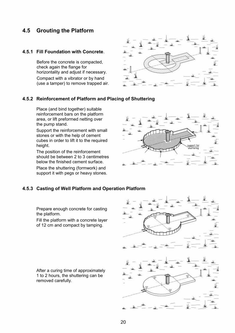
20
4.5 Grouting the Platform 4.5.1 Fill Foundation with Concrete.
Before the concrete is compacted, check again the flange for horizontality and adjust if necessary. Compact with a vibrator or by hand (use a tamper) to remove trapped air.
4.5.2 Reinforcement of Platform and Placing of Shuttering
Place (and bind together) suitable reinforcement bars on the platform area, or lift preformed netting over the pump stand. Support the reinforcement with small stones or with the help of cement cubes in order to lift it to the required height. The position of the reinforcement should be between 2 to 3 centimetres below the finished cement surface. Place the shuttering (formwork) and support it with pegs or heavy stones.
4.5.3 Casting of Well Platform and Operation Platform
Prepare enough concrete for casting the platform. Fill the platform with a concrete layer of 12 cm and compact by tamping.
After a curing time of approximately 1 to 2 hours, the shuttering can be removed carefully.
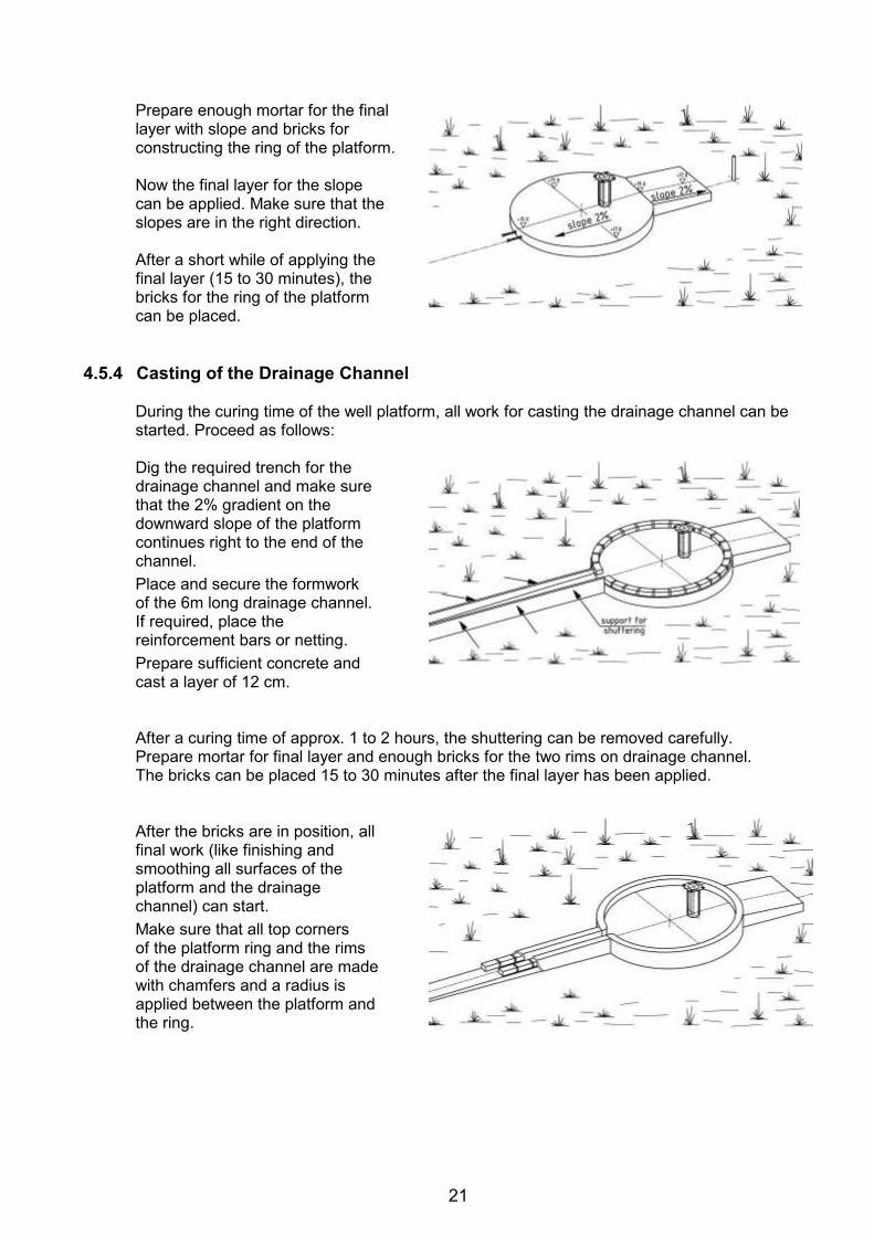
21
Prepare enough mortar for the final layer with slope and bricks for constructing the ring of the platform.
Now the final layer for the slope can be applied. Make sure that the slopes are in the right direction.
After a short while of applying the final layer (15 to 30 minutes), the bricks for the ring of the platform can be placed.
4.5.4 Casting of the Drainage Channel
During the curing time of the well platform, all work for casting the drainage channel can be started. Proceed as follows:
Dig the required trench for the drainage channel and make sure that the 2% gradient on the downward slope of the platform continues right to the end of the channel. Place and secure the formwork of the 6m long drainage channel. If required, place the reinforcement bars or netting. Prepare sufficient concrete and cast a layer of 12 cm.
After a curing time of approx. 1 to 2 hours, the shuttering can be removed carefully. Prepare mortar for final layer and enough bricks for the two rims on drainage channel. The bricks can be placed 15 to 30 minutes after the final layer has been applied.
After the bricks are in position, all final work (like finishing and smoothing all surfaces of the platform and the drainage channel) can start. Make sure that all top corners of the platform ring and the rims of the drainage channel are made with chamfers and a radius is applied between the platform and the ring.
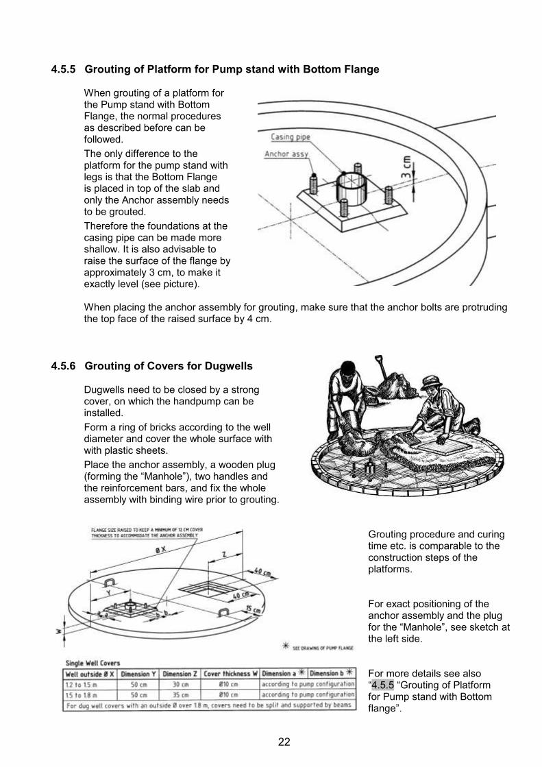
22
4.5.5 Grouting of Platform for Pump stand with Bottom Flange
When grouting of a platform for the Pump stand with Bottom Flange, the normal procedures as described before can be followed. The only difference to the platform for the pump stand with legs is that the Bottom Flange is placed in top of the slab and only the Anchor assembly needs to be grouted. Therefore the foundations at the casing pipe can be made more shallow. It is also advisable to raise the surface of the flange by approximately 3 cm, to make it exactly level (see picture).
When placing the anchor assembly for grouting, make sure that the anchor bolts are protruding the top face of the raised surface by 4 cm.
4.5.6 Grouting of Covers for Dugwells
Dugwells need to be closed by a strong cover, on which the handpump can be installed. Form a ring of bricks according to the well diameter and cover the whole surface with with plastic sheets. Place the anchor assembly, a wooden plug (forming the “Manhole”), two handles and the reinforcement bars, and fix the whole assembly with binding wire prior to grouting.
Grouting procedure and curing time etc. is comparable to the construction steps of the platforms.
For exact positioning of the anchor assembly and the plug for the “Manhole”, see sketch at the left side.
For more details see also “4.5.5 “Grouting of Platform for Pump stand with Bottom flange”.
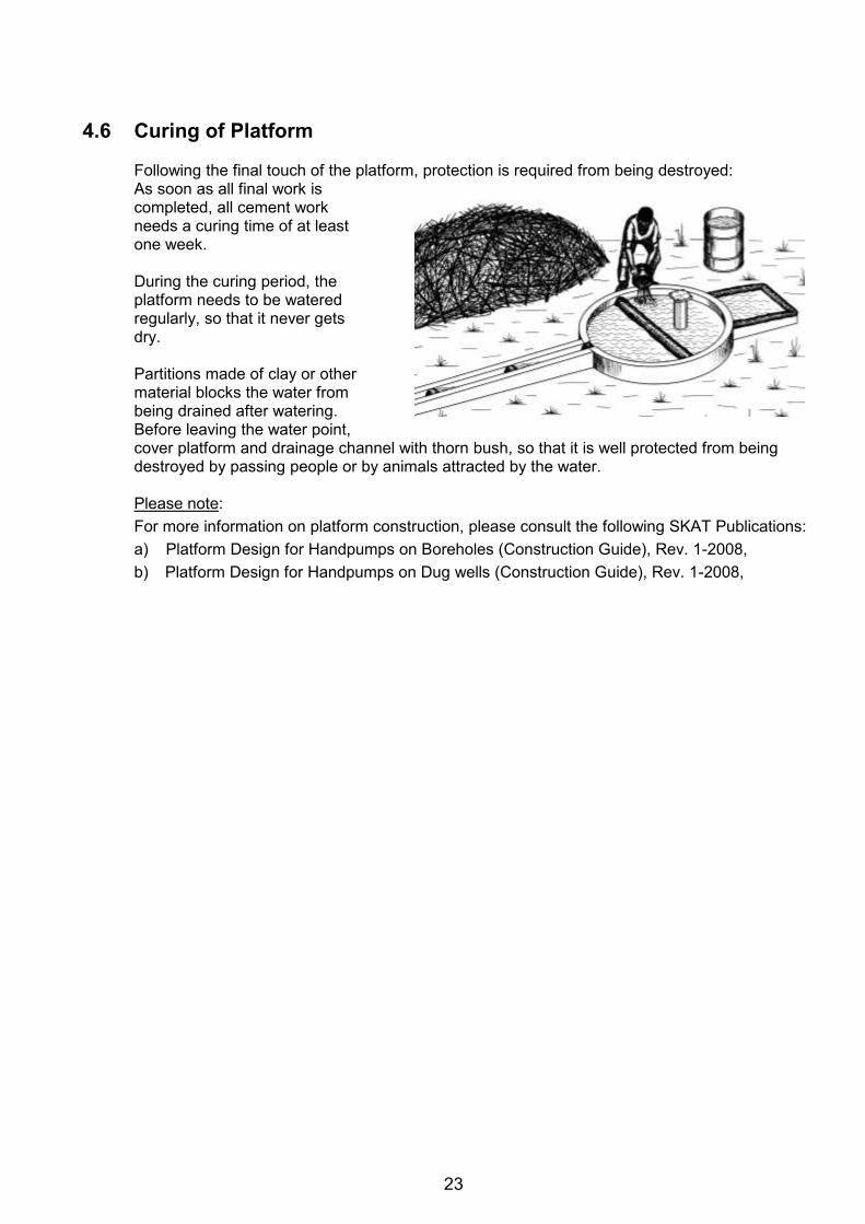
23
4.6 Curing of Platform
Following the final touch of the platform, protection is required from being destroyed: As soon as all final work is completed, all cement work needs a curing time of at least one week.
During the curing period, the platform needs to be watered regularly, so that it never gets dry.
Partitions made of clay or other material blocks the water from being drained after watering. Before leaving the water point, cover platform and drainage channel with thorn bush, so that it is well protected from being destroyed by passing people or by animals attracted by the water.
Please note: For more information on platform construction, please consult the following SKAT Publications: a) Platform Design for Handpumps on Boreholes (Construction Guide), Rev. 1-2008, b) Platform Design for Handpumps on Dug wells (Construction Guide), Rev. 1-2008,
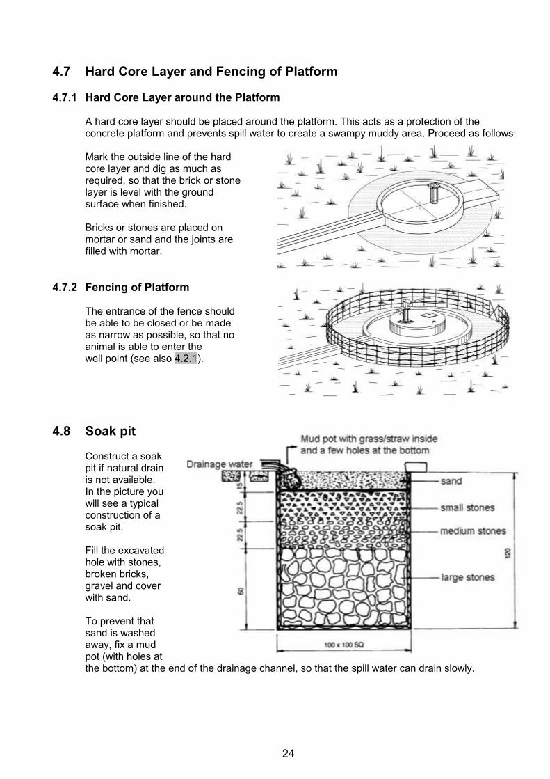
24
4.7 Hard Core Layer and Fencing of Platform 4.7.1 Hard Core Layer around the Platform
A hard core layer should be placed around the platform. This acts as a protection of the concrete platform and prevents spill water to create a swampy muddy area. Proceed as follows:
Mark the outside line of the hard core layer and dig as much as required, so that the brick or stone layer is level with the ground surface when finished.
Bricks or stones are placed on mortar or sand and the joints are filled with mortar.
4.7.2 Fencing of Platform
The entrance of the fence should be able to be closed or be made as narrow as possible, so that no animal is able to enter the well point (see also 4.2.1).
4.8 Soak pit
Construct a soak pit if natural drain is not available. In the picture you will see a typical construction of a soak pit.
Fill the excavated hole with stones, broken bricks, gravel and cover with sand.
To prevent that sand is washed away, fix a mud pot (with holes at the bottom) at the end of the drainage channel, so that the spill water can drain slowly.
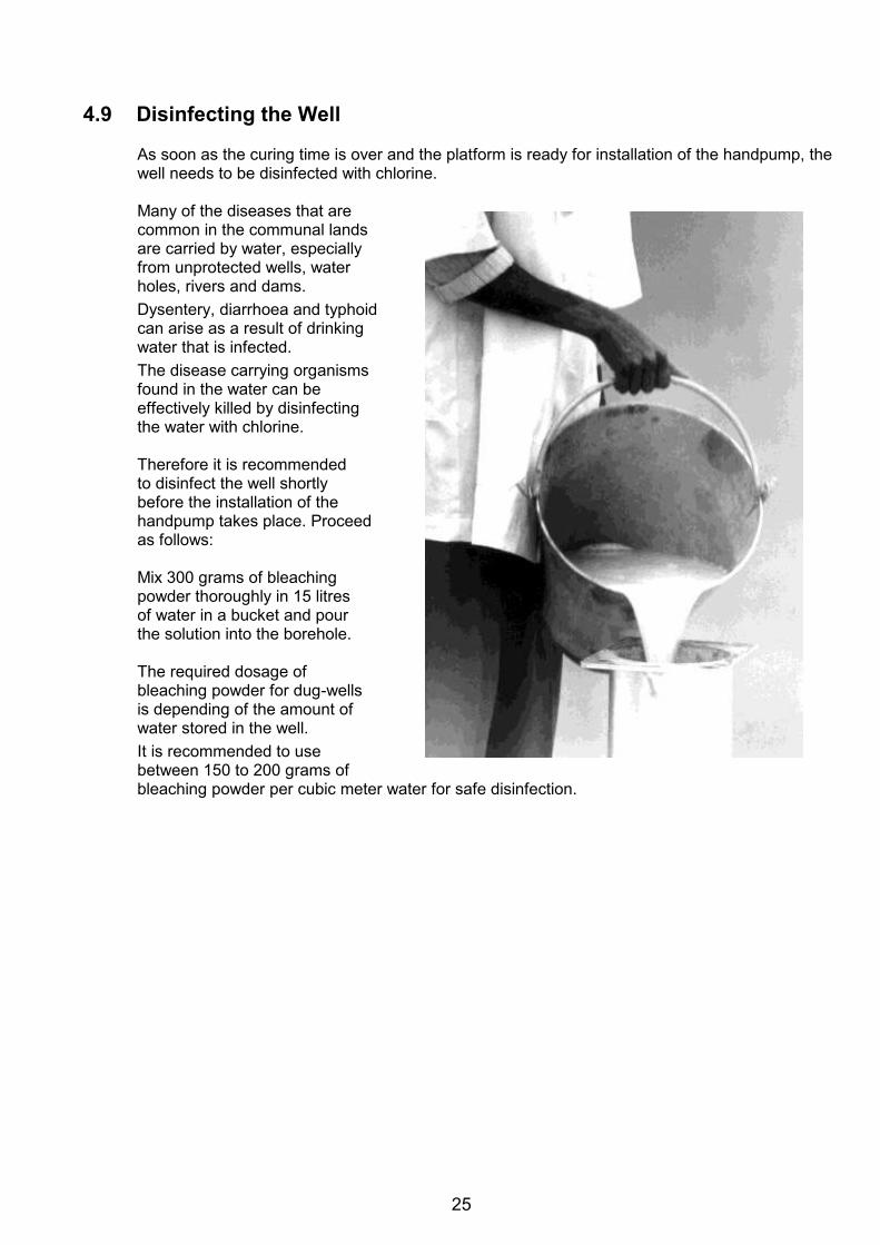
25
4.9 Disinfecting the Well
As soon as the curing time is over and the platform is ready for installation of the handpump, the well needs to be disinfected with chlorine.
Many of the diseases that are common in the communal lands are carried by water, especially from unprotected wells, water holes, rivers and dams. Dysentery, diarrhoea and typhoid can arise as a result of drinking water that is infected. The disease carrying organisms found in the water can be effectively killed by disinfecting the water with chlorine.
Therefore it is recommended to disinfect the well shortly before the installation of the handpump takes place. Proceed as follows:
Mix 300 grams of bleaching powder thoroughly in 15 litres of water in a bucket and pour the solution into the borehole.
The required dosage of bleaching powder for dug-wells is depending of the amount of water stored in the well. It is recommended to use between 150 to 200 grams of bleaching powder per cubic meter water for safe disinfection.
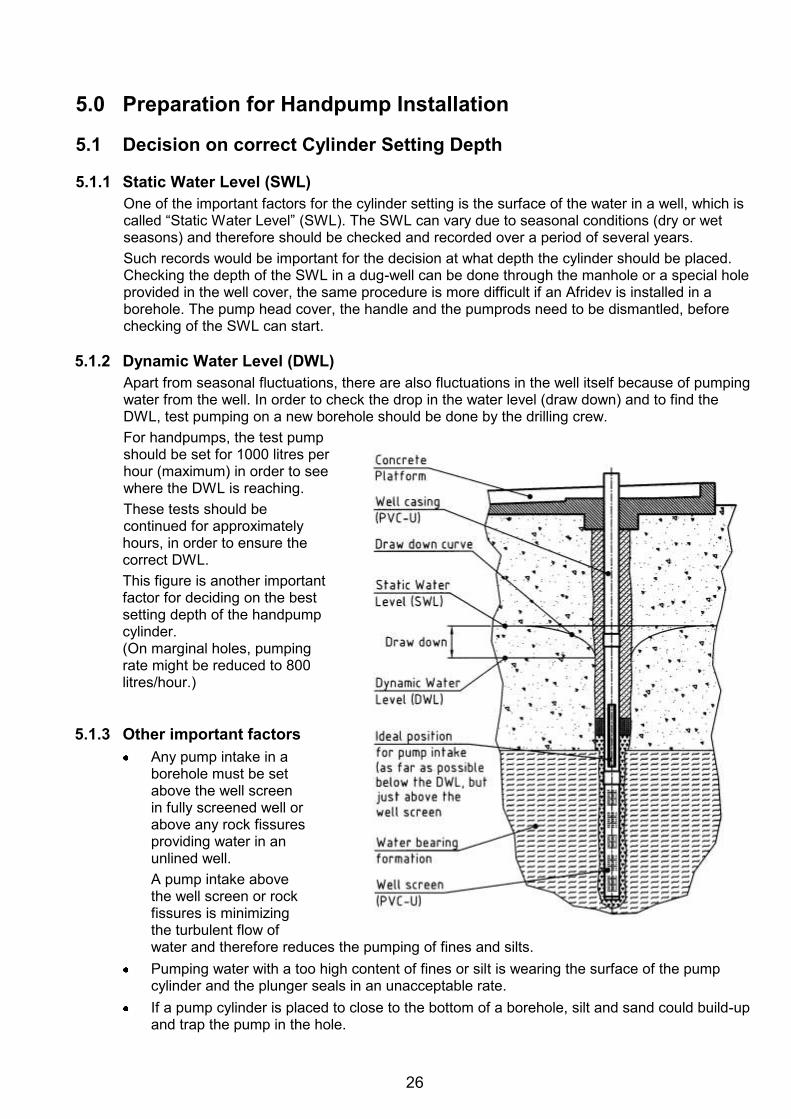
26
5.0 Preparation for Handpump Installation 5.1 Decision on correct Cylinder Setting Depth 5.1.1 Static Water Level (SWL)
One of the important factors for the cylinder setting is the surface of the water in a well, which is called “Static Water Level” (SWL). The SWL can vary due to seasonal conditions (dry or wet seasons) and therefore should be checked and recorded over a period of several years. Such records would be important for the decision at what depth the cylinder should be placed. Checking the depth of the SWL in a dug-well can be done through the manhole or a special hole provided in the well cover, the same procedure is more difficult if an Afridev is installed in a borehole. The pump head cover, the handle and the pumprods need to be dismantled, before checking of the SWL can start.
5.1.2 Dynamic Water Level (DWL)
Apart from seasonal fluctuations, there are also fluctuations in the well itself because of pumping water from the well. In order to check the drop in the water level (draw down) and to find the DWL, test pumping on a new borehole should be done by the drilling crew. For handpumps, the test pump should be set for 1000 litres per hour (maximum) in order to see where the DWL is reaching. These tests should be continued for approximately hours, in order to ensure the correct DWL. This figure is another important factor for deciding on the best setting depth of the handpump cylinder. (On marginal holes, pumping rate might be reduced to 800 litres/hour.)
5.1.3 Other important factors
Any pump intake in a borehole must be set above the well screen in fully screened well or above any rock fissures providing water in an unlined well. A pump intake above the well screen or rock fissures is minimizing the turbulent flow of water and therefore reduces the pumping of fines and silts.
Pumping water with a too high content of fines or silt is wearing the surface of the pump cylinder and the plunger seals in an unacceptable rate.
If a pump cylinder is placed to close to the bottom of a borehole, silt and sand could build-up and trap the pump in the hole.
27
5.1.4 Cylinder setting in Boreholes
Check the depth of the DWL and the depth where the well screen starts (information must be available from the drilling crew). The start of the well screen should be considerably lower than the DWL. If there were a large difference, it would be ideal to place the cylinder approximately 1 meter above the well screen.
Check the SWL regularly, especially during the dry season, in order to avoid that the newly installed pump is running dry. Should the cylinder setting depth be critical during the dry season, add one length of riser pipe and one pumprod.
5.1.5 Cylinder setting in Dug-wells
The cylinder setting for dug-wells is not so critical, because the SWL can be checked regularly through the manhole. It is advised to place the cylinder as such, that the suction pipe is at least 0.5 meter above the well ground, to minimise pumping of silt and sand.
Should the SWL drop in the dry season to such a level that the pump is running dry, increase the depth of the dug-well by some meters.
Adjust the rising main by adding additional riser pipes and pumprods.
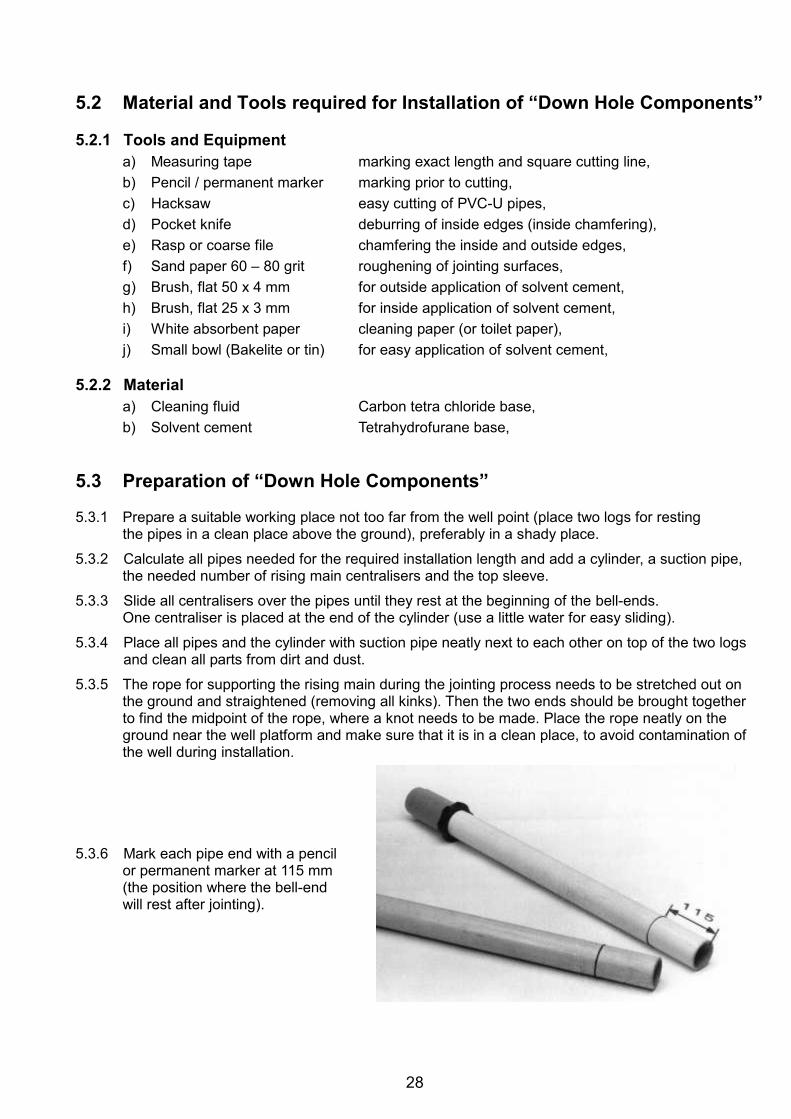
28
5.2 Material and Tools required for Installation of “Down Hole Components” 5.2.1 Tools and Equipment
a) Measuring tape marking exact length and square cutting line, b) Pencil / permanent marker marking prior to cutting, c) Hacksaw easy cutting of PVC-U pipes, d) Pocket knife deburring of inside edges (inside chamfering), e) Rasp or coarse file chamfering the inside and outside edges, f) Sand paper 60 – 80 grit roughening of jointing surfaces, g) Brush, flat 50 x 4 mm for outside application of solvent cement, h) Brush, flat 25 x 3 mm for inside application of solvent cement, i) White absorbent paper cleaning paper (or toilet paper), j) Small bowl (Bakelite or tin) for easy application of solvent cement,
5.2.2 Material
a) Cleaning fluid Carbon tetra chloride base, b) Solvent cement Tetrahydrofurane base,
5.3 Preparation of “Down Hole Components” 5.3.1 Prepare a suitable working place not too far from the well point (place two logs for resting
the pipes in a clean place above the ground), preferably in a shady place.
5.3.2 Calculate all pipes needed for the required installation length and add a cylinder, a suction pipe, the needed number of rising main centralisers and the top sleeve.
5.3.3 Slide all centralisers over the pipes until they rest at the beginning of the bell-ends. One centraliser is placed at the end of the cylinder (use a little water for easy sliding).
5.3.4 Place all pipes and the cylinder with suction pipe neatly next to each other on top of the two logs and clean all parts from dirt and dust.
5.3.5 The rope for supporting the rising main during the jointing process needs to be stretched out on the ground and straightened (removing all kinks). Then the two ends should be brought together to find the midpoint of the rope, where a knot needs to be made. Place the rope neatly on the ground near the well platform and make sure that it is in a clean place, to avoid contamination of the well during installation.
5.3.6 Mark each pipe end with a pencil
or permanent marker at 115 mm (the position where the bell-end will rest after jointing).
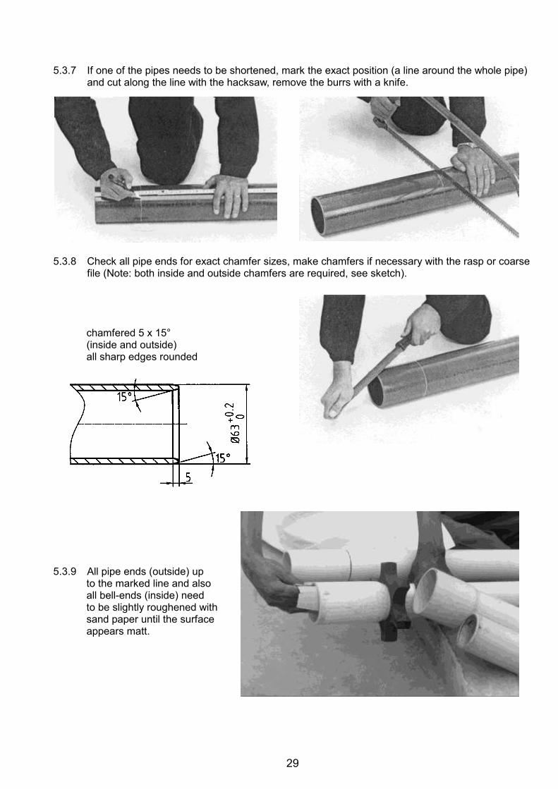
29
5.3.7 If one of the pipes needs to be shortened, mark the exact position (a line around the whole pipe)
and cut along the line with the hacksaw, remove the burrs with a knife. 5.3.8 Check all pipe ends for exact chamfer sizes, make chamfers if necessary with the rasp or coarse
file (Note: both inside and outside chamfers are required, see sketch).
chamfered 5 x 15° (inside and outside) all sharp edges rounded
5.3.9 All pipe ends (outside) up
to the marked line and also all bell-ends (inside) need to be slightly roughened with sand paper until the surface appears matt.
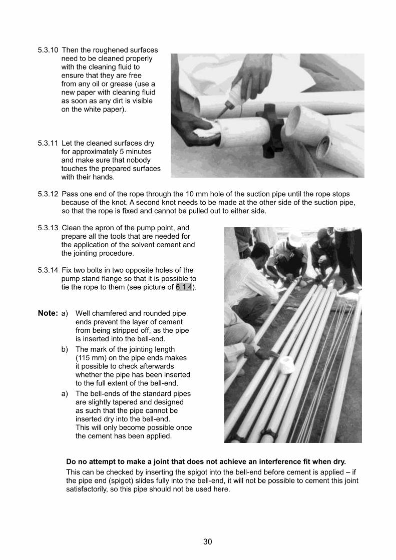
30
5.3.10 Then the roughened surfaces
need to be cleaned properly with the cleaning fluid to ensure that they are free from any oil or grease (use a new paper with cleaning fluid as soon as any dirt is visible on the white paper).
5.3.11 Let the cleaned surfaces dry
for approximately 5 minutes and make sure that nobody touches the prepared surfaces with their hands.
5.3.12 Pass one end of the rope through the 10 mm hole of the suction pipe until the rope stops
because of the knot. A second knot needs to be made at the other side of the suction pipe, so that the rope is fixed and cannot be pulled out to either side.
5.3.13 Clean the apron of the pump point, and
prepare all the tools that are needed for the application of the solvent cement and the jointing procedure.
5.3.14 Fix two bolts in two opposite holes of the
pump stand flange so that it is possible to tie the rope to them (see picture of 6.1.4).
Note: a) Well chamfered and rounded pipe
ends prevent the layer of cement from being stripped off, as the pipe is inserted into the bell-end.
b) The mark of the jointing length (115 mm) on the pipe ends makes it possible to check afterwards whether the pipe has been inserted to the full extent of the bell-end.
a) The bell-ends of the standard pipes are slightly tapered and designed as such that the pipe cannot be inserted dry into the bell-end. This will only become possible once the cement has been applied.
Do no attempt to make a joint that does not achieve an interference fit when dry. This can be checked by inserting the spigot into the bell-end before cement is applied – if the pipe end (spigot) slides fully into the bell-end, it will not be possible to cement this joint satisfactorily, so this pipe should not be used here.
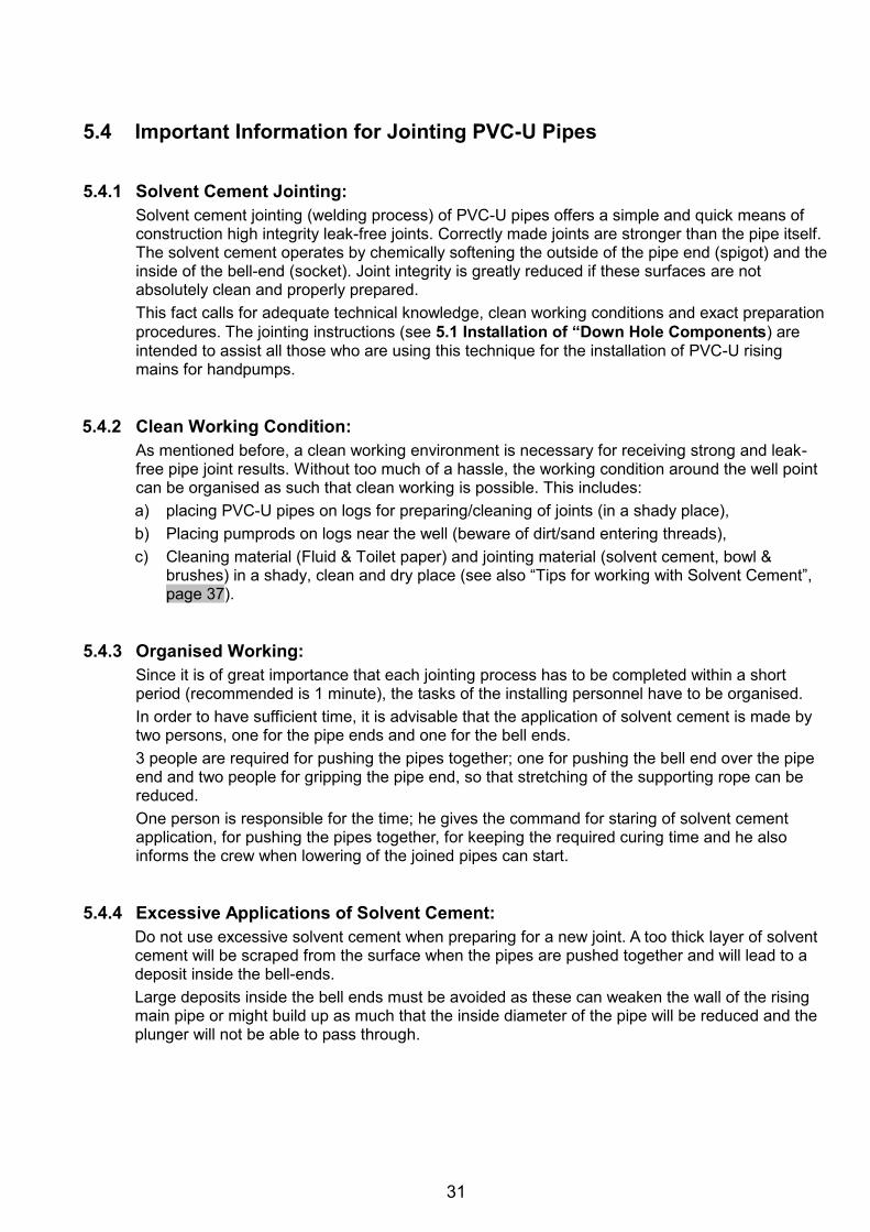
31
5.4 Important Information for Jointing PVC-U Pipes 5.4.1 Solvent Cement Jointing:
Solvent cement jointing (welding process) of PVC-U pipes offers a simple and quick means of construction high integrity leak-free joints. Correctly made joints are stronger than the pipe itself. The solvent cement operates by chemically softening the outside of the pipe end (spigot) and the inside of the bell-end (socket). Joint integrity is greatly reduced if these surfaces are not absolutely clean and properly prepared. This fact calls for adequate technical knowledge, clean working conditions and exact preparation procedures. The jointing instructions (see 5.1 Installation of “Down Hole Components) are intended to assist all those who are using this technique for the installation of PVC-U rising mains for handpumps.
5.4.2 Clean Working Condition:
As mentioned before, a clean working environment is necessary for receiving strong and leak-free pipe joint results. Without too much of a hassle, the working condition around the well point can be organised as such that clean working is possible. This includes: a) placing PVC-U pipes on logs for preparing/cleaning of joints (in a shady place), b) Placing pumprods on logs near the well (beware of dirt/sand entering threads), c) Cleaning material (Fluid & Toilet paper) and jointing material (solvent cement, bowl &
brushes) in a shady, clean and dry place (see also “Tips for working with Solvent Cement”, page 37).
5.4.3 Organised Working:
Since it is of great importance that each jointing process has to be completed within a short period (recommended is 1 minute), the tasks of the installing personnel have to be organised. In order to have sufficient time, it is advisable that the application of solvent cement is made by two persons, one for the pipe ends and one for the bell ends. 3 people are required for pushing the pipes together; one for pushing the bell end over the pipe end and two people for gripping the pipe end, so that stretching of the supporting rope can be reduced. One person is responsible for the time; he gives the command for staring of solvent cement application, for pushing the pipes together, for keeping the required curing time and he also informs the crew when lowering of the joined pipes can start.
5.4.4 Excessive Applications of Solvent Cement:
Do not use excessive solvent cement when preparing for a new joint. A too thick layer of solvent cement will be scraped from the surface when the pipes are pushed together and will lead to a deposit inside the bell-ends. Large deposits inside the bell ends must be avoided as these can weaken the wall of the rising main pipe or might build up as much that the inside diameter of the pipe will be reduced and the plunger will not be able to pass through.
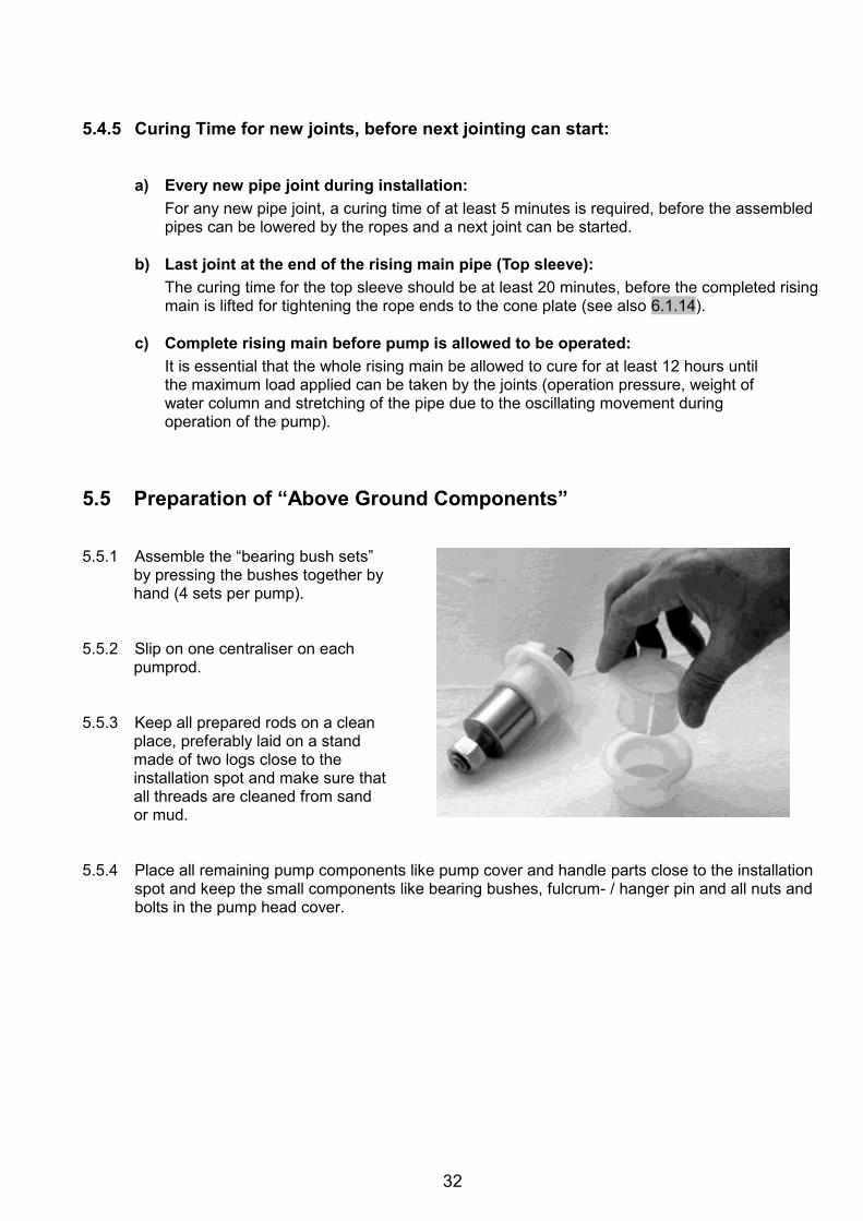
32
5.4.5 Curing Time for new joints, before next jointing can start:
a) Every new pipe joint during installation: For any new pipe joint, a curing time of at least 5 minutes is required, before the assembled pipes can be lowered by the ropes and a next joint can be started.
b) Last joint at the end of the rising main pipe (Top sleeve):
The curing time for the top sleeve should be at least 20 minutes, before the completed rising main is lifted for tightening the rope ends to the cone plate (see also 6.1.14).
c) Complete rising main before pump is allowed to be operated:
It is essential that the whole rising main be allowed to cure for at least 12 hours until the maximum load applied can be taken by the joints (operation pressure, weight of water column and stretching of the pipe due to the oscillating movement during operation of the pump).
5.5 Preparation of “Above Ground Components” 5.5.1 Assemble the “bearing bush sets”
by pressing the bushes together by hand (4 sets per pump).
5.5.2 Slip on one centraliser on each
pumprod. 5.5.3 Keep all prepared rods on a clean
place, preferably laid on a stand made of two logs close to the installation spot and make sure that all threads are cleaned from sand or mud.
5.5.4 Place all remaining pump components like pump cover and handle parts close to the installation
spot and keep the small components like bearing bushes, fulcrum- / hanger pin and all nuts and bolts in the pump head cover.
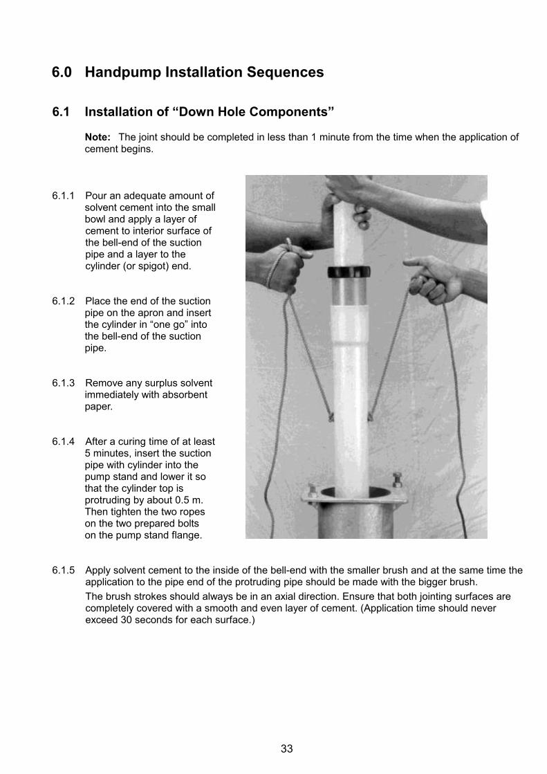
33
6.0 Handpump Installation Sequences 6.1 Installation of “Down Hole Components”
Note: The joint should be completed in less than 1 minute from the time when the application of cement begins.
6.1.1 Pour an adequate amount of
solvent cement into the small bowl and apply a layer of cement to interior surface of the bell-end of the suction pipe and a layer to the cylinder (or spigot) end.
6.1.2 Place the end of the suction
pipe on the apron and insert the cylinder in “one go” into the bell-end of the suction pipe.
6.1.3 Remove any surplus solvent
immediately with absorbent paper.
6.1.4 After a curing time of at least
5 minutes, insert the suction pipe with cylinder into the pump stand and lower it so that the cylinder top is protruding by about 0.5 m. Then tighten the two ropes on the two prepared bolts on the pump stand flange.
6.1.5 Apply solvent cement to the inside of the bell-end with the smaller brush and at the same time the
application to the pipe end of the protruding pipe should be made with the bigger brush. The brush strokes should always be in an axial direction. Ensure that both jointing surfaces are completely covered with a smooth and even layer of cement. (Application time should never exceed 30 seconds for each surface.)
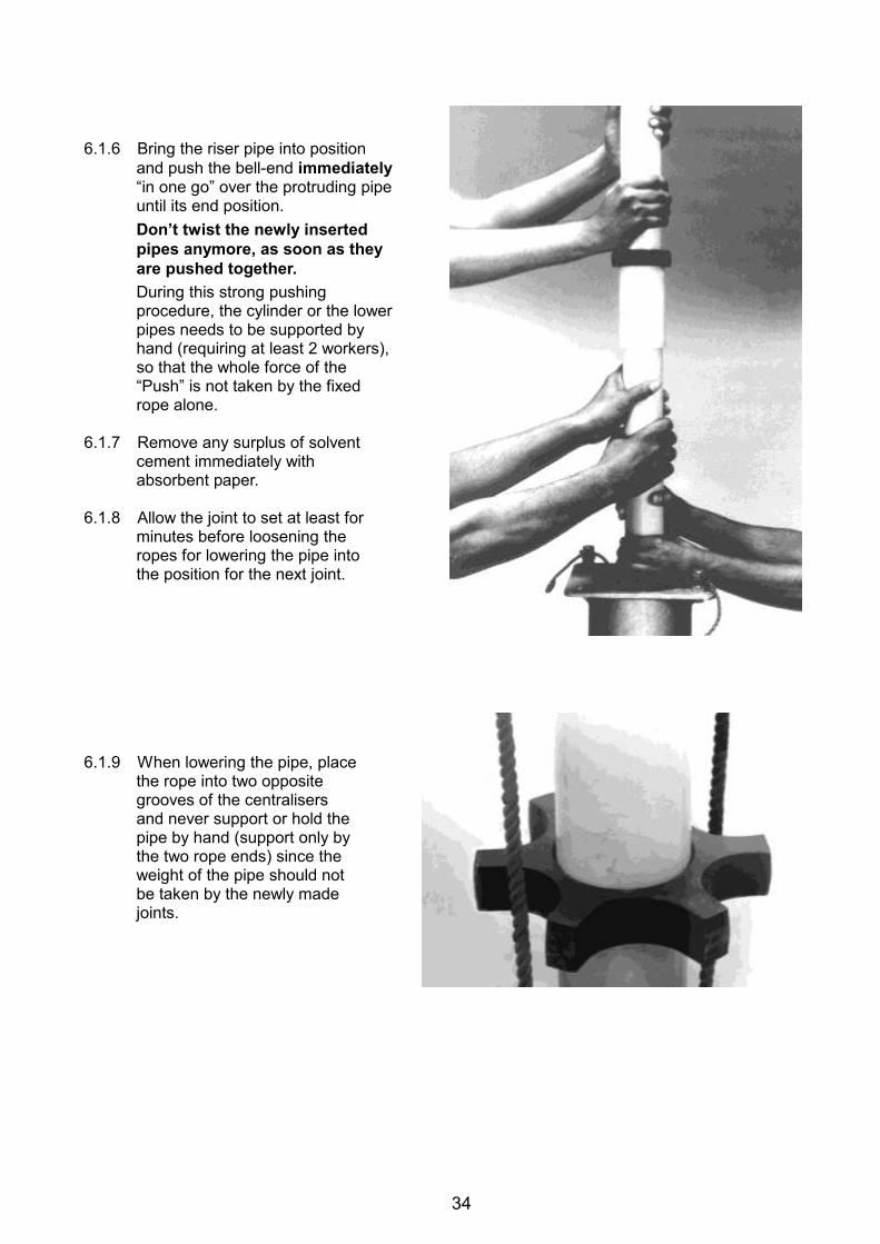
34
6.1.6 Bring the riser pipe into position
and push the bell-end immediately “in one go” over the protruding pipe until its end position. Don’t twist the newly inserted pipes anymore, as soon as they are pushed together. During this strong pushing procedure, the cylinder or the lower pipes needs to be supported by hand (requiring at least 2 workers), so that the whole force of the “Push” is not taken by the fixed rope alone.
6.1.7 Remove any surplus of solvent
cement immediately with absorbent paper.
6.1.8 Allow the joint to set at least for
minutes before loosening the ropes for lowering the pipe into the position for the next joint.
6.1.9 When lowering the pipe, place
the rope into two opposite grooves of the centralisers and never support or hold the pipe by hand (support only by the two rope ends) since the weight of the pipe should not be taken by the newly made joints.
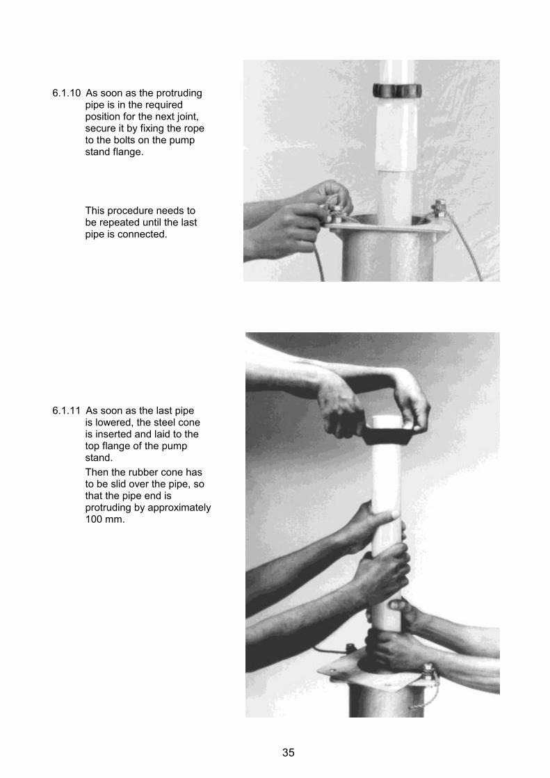
35
6.1.10 As soon as the protruding
pipe is in the required position for the next joint, secure it by fixing the rope to the bolts on the pump stand flange.
This procedure needs to be repeated until the last pipe is connected.
6.1.11 As soon as the last pipe
is lowered, the steel cone is inserted and laid to the top flange of the pump stand. Then the rubber cone has to be slid over the pipe, so that the pipe end is protruding by approximately 100 mm.
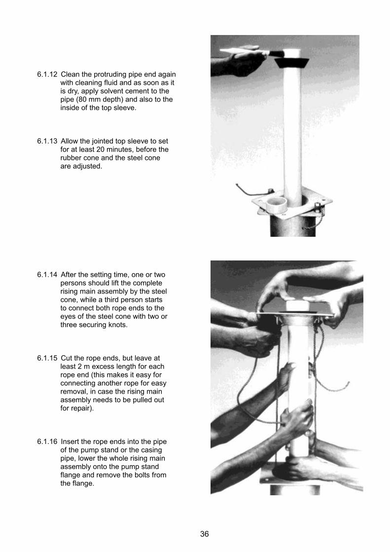
36
6.1.12 Clean the protruding pipe end again
with cleaning fluid and as soon as it is dry, apply solvent cement to the pipe (80 mm depth) and also to the inside of the top sleeve.
6.1.13 Allow the jointed top sleeve to set
for at least 20 minutes, before the rubber cone and the steel cone are adjusted.
6.1.14 After the setting time, one or two
persons should lift the complete rising main assembly by the steel cone, while a third person starts to connect both rope ends to the eyes of the steel cone with two or three securing knots.
6.1.15 Cut the rope ends, but leave at
least 2 m excess length for each rope end (this makes it easy for connecting another rope for easy removal, in case the rising main assembly needs to be pulled out for repair).
6.1.16 Insert the rope ends into the pipe
of the pump stand or the casing pipe, lower the whole rising main assembly onto the pump stand flange and remove the bolts from the flange.
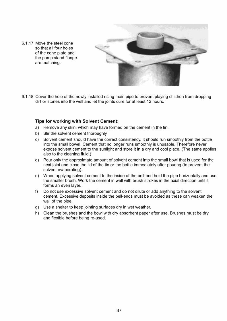
37
6.1.17 Move the steel cone
so that all four holes of the cone plate and the pump stand flange are matching.
6.1.18 Cover the hole of the newly installed rising main pipe to prevent playing children from dropping
dirt or stones into the well and let the joints cure for at least 12 hours.
Tips for working with Solvent Cement: a) Remove any skin, which may have formed on the cement in the tin. b) Stir the solvent cement thoroughly. c) Solvent cement should have the correct consistency. It should run smoothly from the bottle
into the small bowel. Cement that no longer runs smoothly is unusable. Therefore never expose solvent cement to the sunlight and store it in a dry and cool place. (The same applies also to the cleaning fluid.)
d) Pour only the approximate amount of solvent cement into the small bowl that is used for the next joint and close the lid of the tin or the bottle immediately after pouring (to prevent the solvent evaporating).
e) When applying solvent cement to the inside of the bell-end hold the pipe horizontally and use the smaller brush. Work the cement in well with brush strokes in the axial direction until it forms an even layer.
f) Do not use excessive solvent cement and do not dilute or add anything to the solvent cement. Excessive deposits inside the bell-ends must be avoided as these can weaken the wall of the pipe.
g) Use a shelter to keep jointing surfaces dry in wet weather. h) Clean the brushes and the bowl with dry absorbent paper after use. Brushes must be dry
and flexible before being re-used.
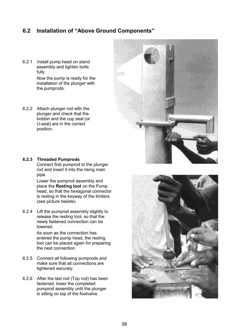
38
6.2 Installation of “Above Ground Components” 6.2.1 Install pump head on stand
assembly and tighten bolts fully. Now the pump is ready for the installation of the plunger with the pumprods.
6.2.2 Attach plunger rod with the
plunger and check that the bobbin and the cup seal (or U-seal) are in the correct position.
6.2.3 Threaded Pumprods
Connect first pumprod to the plunger rod and insert it into the rising main pipe. Lower the pumprod assembly and place the Resting tool on the Pump head, so that the hexagonal connector is resting in the keyway of the limiters (see picture beside).
6.2.4 Lift the pumprod assembly slightly to
release the resting tool, so that the newly fastened connection can be lowered. As soon as the connection has entered the pump head, the resting tool can be placed again for preparing the next connection.
6.2.5 Connect all following pumprods and
make sure that all connections are tightened securely.
6.2.6 After the last rod (Top rod) has been
fastened, lower the completed pumprod assembly until the plunger is sitting on top of the footvalve.
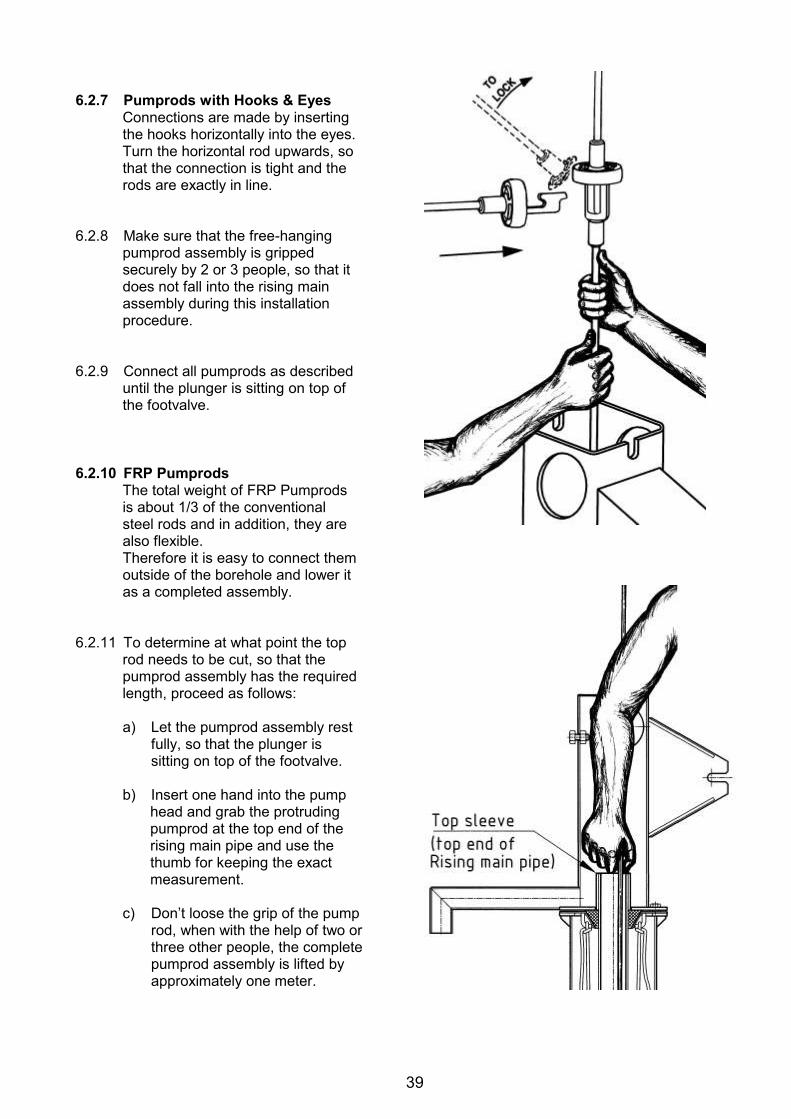
39
6.2.7 Pumprods with Hooks & Eyes
Connections are made by inserting the hooks horizontally into the eyes. Turn the horizontal rod upwards, so that the connection is tight and the rods are exactly in line.
6.2.8 Make sure that the free-hanging
pumprod assembly is gripped securely by 2 or 3 people, so that it does not fall into the rising main assembly during this installation procedure.
6.2.9 Connect all pumprods as described
until the plunger is sitting on top of the footvalve.
6.2.10 FRP Pumprods
The total weight of FRP Pumprods is about 1/3 of the conventional steel rods and in addition, they are also flexible. Therefore it is easy to connect them outside of the borehole and lower it as a completed assembly.
6.2.11 To determine at what point the top
rod needs to be cut, so that the pumprod assembly has the required length, proceed as follows:
a) Let the pumprod assembly rest
fully, so that the plunger is sitting on top of the footvalve.
b) Insert one hand into the pump
head and grab the protruding pumprod at the top end of the rising main pipe and use the thumb for keeping the exact measurement.
c) Don’t loose the grip of the pump
rod, when with the help of two or three other people, the complete pumprod assembly is lifted by approximately one meter.
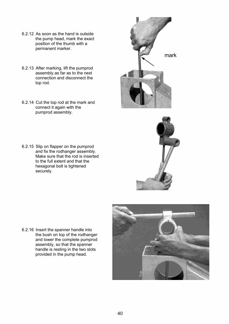
40
6.2.12 As soon as the hand is outside
the pump head, mark the exact position of the thumb with a permanent marker.
6.2.13 After marking, lift the pumprod
assembly as far as to the next connection and disconnect the top rod.
6.2.14 Cut the top rod at the mark and
connect it again with the pumprod assembly.
6.2.15 Slip on flapper on the pumprod
and fix the rodhanger assembly. Make sure that the rod is inserted to the full extent and that the hexagonal bolt is tightened securely.
6.2.16 Insert the spanner handle into
the bush on top of the rodhanger and lower the complete pumprod assembly, so that the spanner handle is resting in the two slots provided in the pump head.
mark
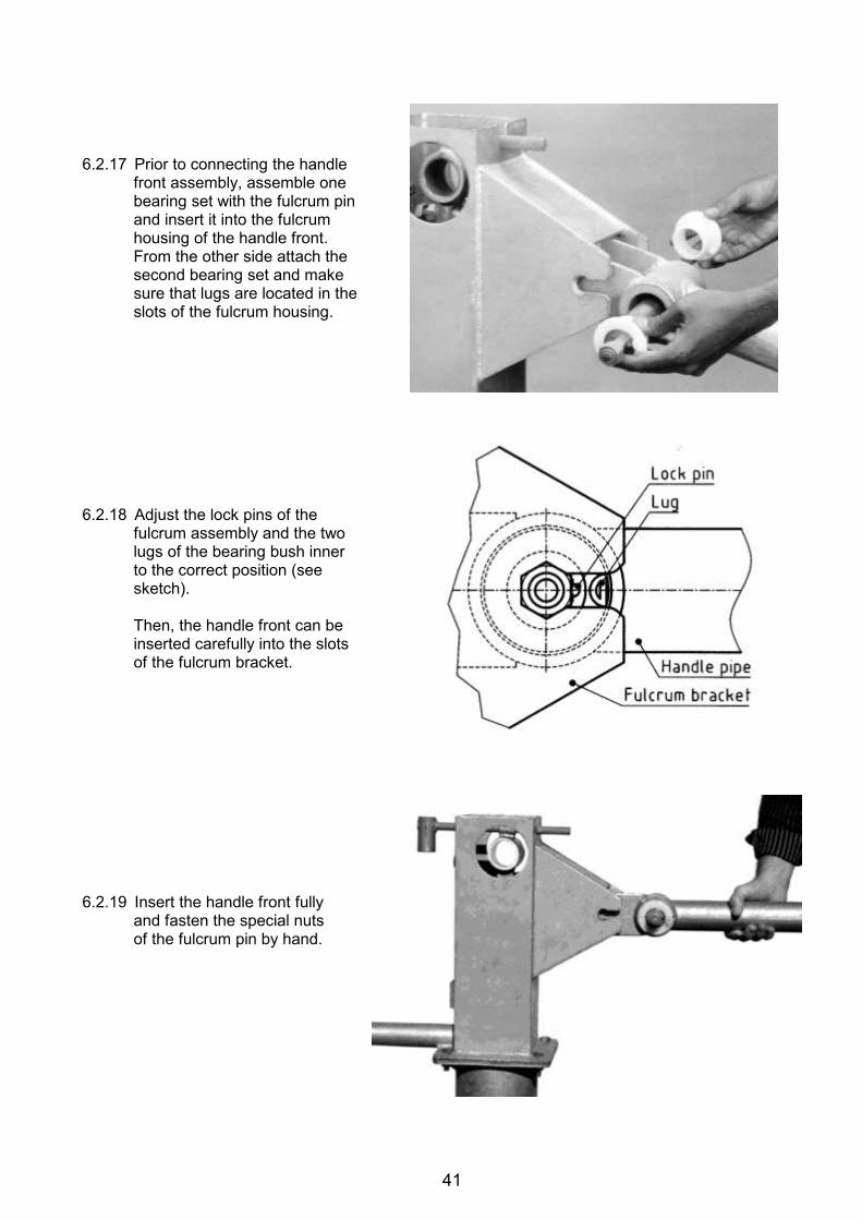
41
6.2.17 Prior to connecting the handle
front assembly, assemble one bearing set with the fulcrum pin and insert it into the fulcrum housing of the handle front. From the other side attach the second bearing set and make sure that lugs are located in the slots of the fulcrum housing.
6.2.18 Adjust the lock pins of the
fulcrum assembly and the two lugs of the bearing bush inner to the correct position (see sketch).
Then, the handle front can be inserted carefully into the slots of the fulcrum bracket.
6.2.19 Insert the handle front fully
and fasten the special nuts of the fulcrum pin by hand.
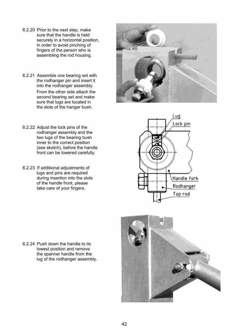
42
6.2.20 Prior to the next step, make
sure that the handle is held securely in a horizontal position, in order to avoid pinching of fingers of the person who is assembling the rod housing.
6.2.21 Assemble one bearing set with
the rodhanger pin and insert it into the rodhanger assembly. From the other side attach the second bearing set and make sure that lugs are located in the slots of the hanger bush.
6.2.22 Adjust the lock pins of the
rodhanger assembly and the two lugs of the bearing bush inner to the correct position (see sketch), before the handle front can be lowered carefully.
6.2.23 If additional adjustments of
lugs and pins are required during insertion into the slots of the handle front, please take care of your fingers.
6.2.24 Push down the handle to its
lowest position and remove the spanner handle from the lug of the rodhanger assembly.

43
6.2.25 Prior to fastening the nuts of
the fulcrum- and hanger pin, make sure that they are in correct position. Tighten nuts securely.
6.2.26 Insert the handle rear assembly
into the handle front assembly and tighten adjustment bolt securely. Balancing of the handle can only take place, once the rising main pipe is completely filled with water. A correctly balanced handle remains in horizontal position when left free.
6.2.27 Operate the handle till the water flows out of the spout.
The number of strokes required until full flow is reached, is determined by the installation depth of the cylinder (the installation depth divided by the maximal handle stroke indicates approximately the number of full strokes required). Due to the slightly bigger diameter of the riser pipes, about six full strokes are required for lifting the water by 1 m.
6.2.28 Initially the first water might be turbid and smelling from chorine, but after 15 to 30 minutes of
operation it should become clear. 6.2.29 Now the following checks should be carried out:
a) All nuts and bolts are well secured, b) Effort required to operate the pump is normal, c) No leakage in the rising main (wait for 5 minutes to see whether water in the rising main
assembly is receding, d) Water discharge (approx. 40 strokes per minute) is above 16 litres, e) Existence of identification mark of the support agency (painted or stamped).
6.2.30 Fill in the installation
card (see Annex 5a). A copy of the card should be given to the users committee or to the handpump caretaker.
6.2.31 Fix the cover and
tighten the cover bolt.
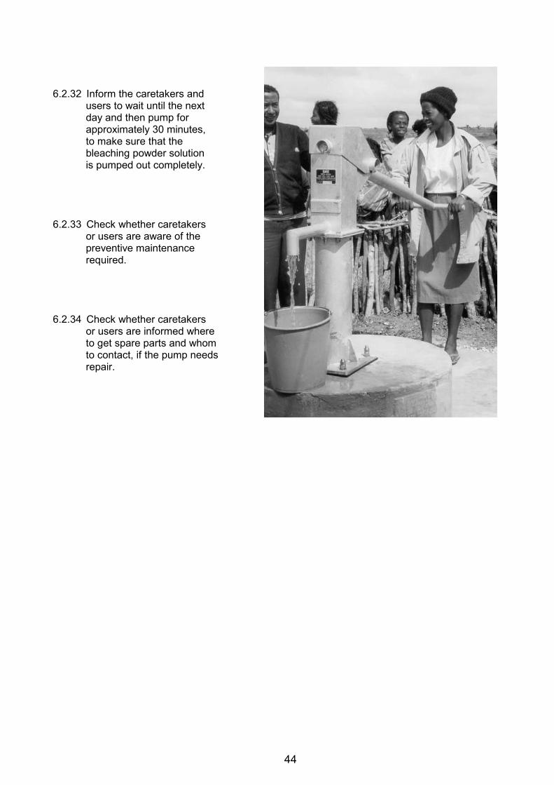
44
6.2.32 Inform the caretakers and
users to wait until the next day and then pump for approximately 30 minutes, to make sure that the bleaching powder solution is pumped out completely.
6.2.33 Check whether caretakers
or users are aware of the preventive maintenance required.
6.2.34 Check whether caretakers
or users are informed where to get spare parts and whom to contact, if the pump needs repair.
45
Part 2 Maintenance of the Afridev Handpump 7.0 Preventive Maintenance
Every pump owner, caretaker or the user committee is responsible for the preventive maintenance of the water point (handpump including surrounding) and therefore is entitled to receive regular training from the supplier of the handpump.
Preventive maintenance means regular check-up of the handpump at a fixed time interval and changing of spare parts before they are fully worn. As an example: if the estimated lifetime of a plunger seal is one year, the plunger seal will be changed after a period of one year even if it is still functional. If during a preventive maintenance check, footvalve leakage is noticed, the caretaker will carry out repairs in the footvalve even though the pump has not broken down. Such interventions help in preventing the sudden failure of the pump.
7.1 Preventive Maintenance Checks of Handpump 7.1.1 Weekly checks:
Check that the flange bolts and nuts are tight. Check that the Fulcrum pin nuts and Hanger pin nuts are tight.
7.1.2 Monthly checks:
Check if any fasteners or parts in the pump head are missing. If so, replace the parts. If any unusual noise is noticed, check reason for the same and take corrective actions. Check if the pump stand is shaky during operation. If yes, the stand is loose in the
foundation and contamination of the well can take place. Take corrective measures to repair the foundation.
Check if there is leakage in the pump. If more than 5 strokes are required before water comes out from the spout, it means the pump is leaking beyond an acceptable limit. This needs to be attended to. It may be necessary to replace bobbin / footvalve O-ring or attend to a leaking joint in the rising main. For attending to a defect in the rising main you may need the help of a skilled mechanic. The special leakage test can be conducted as described below.
Carry out a “Leakage- and Discharge Test” (see 7.1.3 and 7.1.4 below). 7.1.3 Leakage Test
Proceed as follows: a) Operate the pump handle until water is flowing from the spout. b) Stop operating the pump handle for approximately 30 minutes. c) Then operate the handle and count exactly how many strokes required until the water is
starting to flow again. If more than 5 full handle strokes are required to make the water flow again, there must be a leakage in the rising main or the footvalve.
Leakage mostly occurs because of worn bobbin or o-ring of the footvalve, disconnected rising main joints or perforated or cracked riser pipes.
Report this problem immediately to the pump mechanic and ask for rectification!
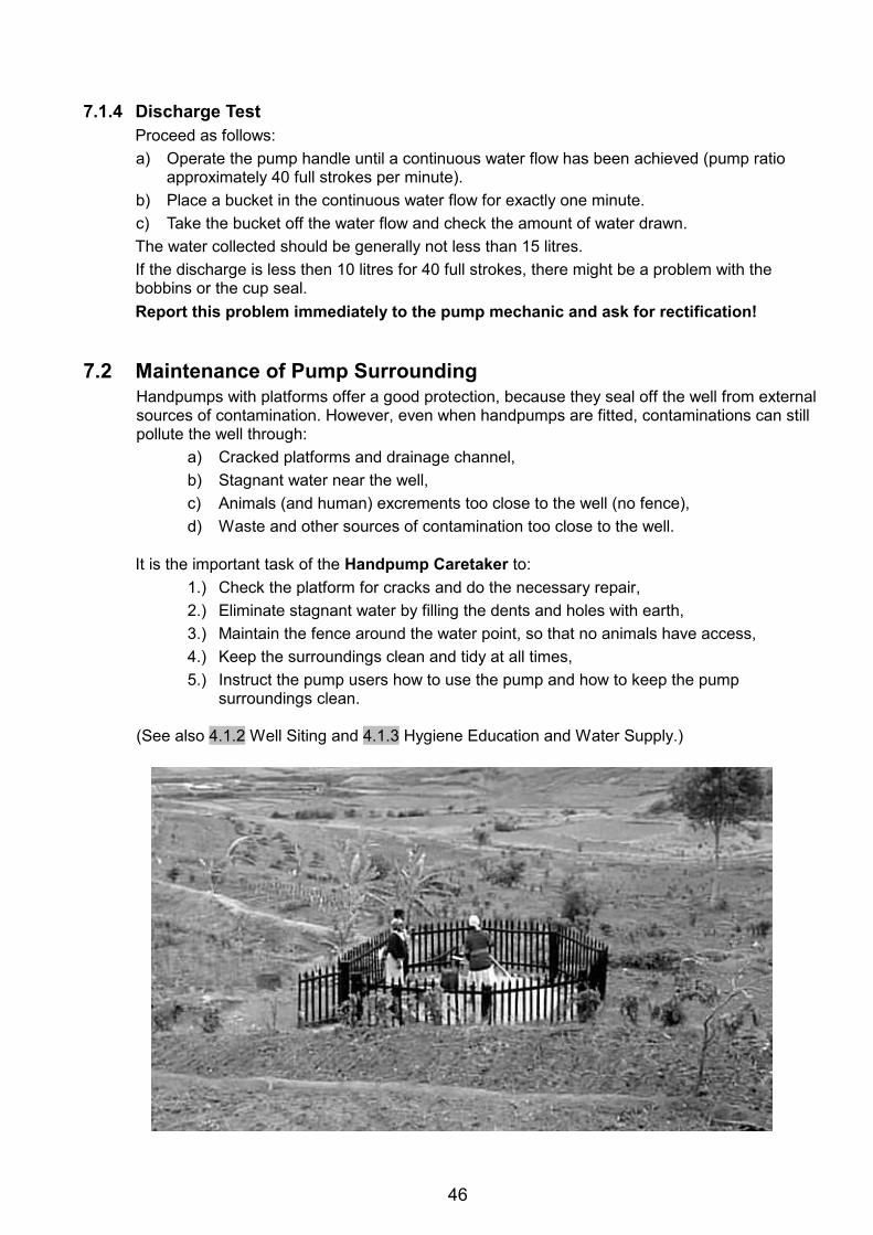
46
7.1.4 Discharge Test
Proceed as follows: a) Operate the pump handle until a continuous water flow has been achieved (pump ratio
approximately 40 full strokes per minute). b) Place a bucket in the continuous water flow for exactly one minute. c) Take the bucket off the water flow and check the amount of water drawn. The water collected should be generally not less than 15 litres. If the discharge is less then 10 litres for 40 full strokes, there might be a problem with the bobbins or the cup seal. Report this problem immediately to the pump mechanic and ask for rectification!
7.2 Maintenance of Pump Surrounding
Handpumps with platforms offer a good protection, because they seal off the well from external sources of contamination. However, even when handpumps are fitted, contaminations can still pollute the well through:
a) Cracked platforms and drainage channel, b) Stagnant water near the well, c) Animals (and human) excrements too close to the well (no fence), d) Waste and other sources of contamination too close to the well.
It is the important task of the Handpump Caretaker to:
1.) Check the platform for cracks and do the necessary repair, 2.) Eliminate stagnant water by filling the dents and holes with earth, 3.) Maintain the fence around the water point, so that no animals have access, 4.) Keep the surroundings clean and tidy at all times, 5.) Instruct the pump users how to use the pump and how to keep the pump
surroundings clean.
(See also 4.1.2 Well Siting and 4.1.3 Hygiene Education and Water Supply.)
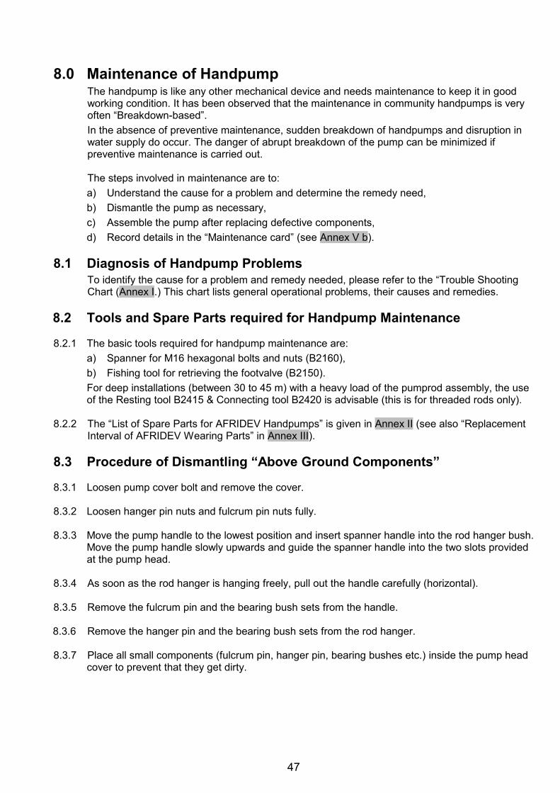
47
8.0 Maintenance of Handpump
The handpump is like any other mechanical device and needs maintenance to keep it in good working condition. It has been observed that the maintenance in community handpumps is very often “Breakdown-based”. In the absence of preventive maintenance, sudden breakdown of handpumps and disruption in water supply do occur. The danger of abrupt breakdown of the pump can be minimized if preventive maintenance is carried out.
The steps involved in maintenance are to: a) Understand the cause for a problem and determine the remedy need, b) Dismantle the pump as necessary, c) Assemble the pump after replacing defective components, d) Record details in the “Maintenance card” (see Annex V b).
8.1 Diagnosis of Handpump Problems
To identify the cause for a problem and remedy needed, please refer to the “Trouble Shooting Chart (Annex I.) This chart lists general operational problems, their causes and remedies.
8.2 Tools and Spare Parts required for Handpump Maintenance 8.2.1 The basic tools required for handpump maintenance are:
a) Spanner for M16 hexagonal bolts and nuts (B2160), b) Fishing tool for retrieving the footvalve (B2150). For deep installations (between 30 to 45 m) with a heavy load of the pumprod assembly, the use of the Resting tool B2415 & Connecting tool B2420 is advisable (this is for threaded rods only).
8.2.2 The “List of Spare Parts for AFRIDEV Handpumps” is given in Annex II (see also “Replacement
Interval of AFRIDEV Wearing Parts” in Annex III). 8.3 Procedure of Dismantling “Above Ground Components” 8.3.1 Loosen pump cover bolt and remove the cover. 8.3.2 Loosen hanger pin nuts and fulcrum pin nuts fully. 8.3.3 Move the pump handle to the lowest position and insert spanner handle into the rod hanger bush.
Move the pump handle slowly upwards and guide the spanner handle into the two slots provided at the pump head.
8.3.4 As soon as the rod hanger is hanging freely, pull out the handle carefully (horizontal). 8.3.5 Remove the fulcrum pin and the bearing bush sets from the handle. 8.3.6 Remove the hanger pin and the bearing bush sets from the rod hanger. 8.3.7 Place all small components (fulcrum pin, hanger pin, bearing bushes etc.) inside the pump head
cover to prevent that they get dirty.
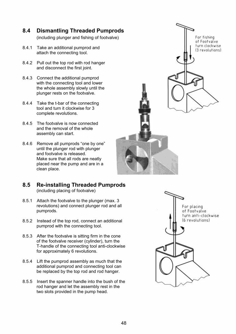
48
8.4 Dismantling Threaded Pumprods
(including plunger and fishing of footvalve) 8.4.1 Take an additional pumprod and
attach the connecting tool. 8.4.2 Pull out the top rod with rod hanger
and disconnect the first joint. 8.4.3 Connect the additional pumprod
with the connecting tool and lower the whole assembly slowly until the plunger rests on the footvalve.
8.4.4 Take the t-bar of the connecting
tool and turn it clockwise for 3 complete revolutions.
8.4.5 The footvalve is now connected
and the removal of the whole assembly can start.
8.4.6 Remove all pumprods “one by one”
until the plunger rod with plunger and footvalve is released. Make sure that all rods are neatly placed near the pump and are in a clean place.
8.5 Re-installing Threaded Pumprods
(including placing of footvalve) 8.5.1 Attach the footvalve to the plunger (max. 3
revolutions) and connect plunger rod and all pumprods.
8.5.2 Instead of the top rod, connect an additional
pumprod with the connecting tool. 8.5.3 After the footvalve is sitting firm in the cone
of the footvalve receiver (cylinder), turn the T-handle of the connecting tool anti-clockwise for approximately 6 revolutions.
8.5.4 Lift the pumprod assembly as much that the
additional pumprod and connecting tool can be replaced by the top rod and rod hanger.
8.5.5 Insert the spanner handle into the bush of the
rod hanger and let the assembly rest in the two slots provided in the pump head.
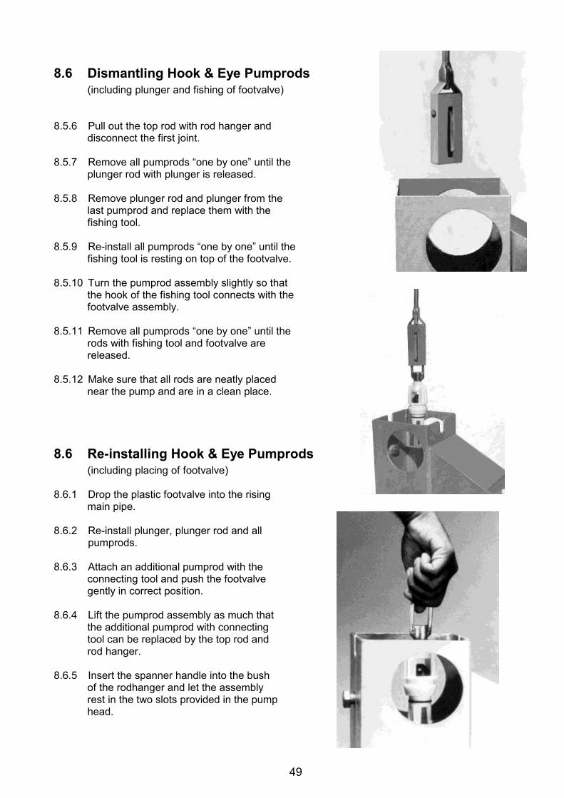
49
8.6 Dismantling Hook & Eye Pumprods
(including plunger and fishing of footvalve) 8.5.6 Pull out the top rod with rod hanger and
disconnect the first joint. 8.5.7 Remove all pumprods “one by one” until the
plunger rod with plunger is released. 8.5.8 Remove plunger rod and plunger from the
last pumprod and replace them with the fishing tool.
8.5.9 Re-install all pumprods “one by one” until the
fishing tool is resting on top of the footvalve. 8.5.10 Turn the pumprod assembly slightly so that
the hook of the fishing tool connects with the footvalve assembly.
8.5.11 Remove all pumprods “one by one” until the
rods with fishing tool and footvalve are released.
8.5.12 Make sure that all rods are neatly placed
near the pump and are in a clean place. 8.6 Re-installing Hook & Eye Pumprods
(including placing of footvalve) 8.6.1 Drop the plastic footvalve into the rising
main pipe. 8.6.2 Re-install plunger, plunger rod and all
pumprods. 8.6.3 Attach an additional pumprod with the
connecting tool and push the footvalve gently in correct position.
8.6.4 Lift the pumprod assembly as much that
the additional pumprod with connecting tool can be replaced by the top rod and rod hanger.
8.6.5 Insert the spanner handle into the bush
of the rodhanger and let the assembly rest in the two slots provided in the pump head.
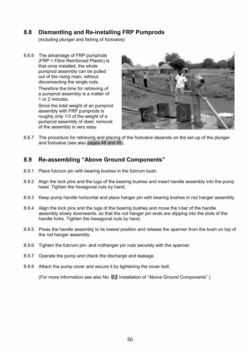
50
8.8 Dismantling and Re-installing FRP Pumprods
(including plunger and fishing of footvalve) 8.6.6 The advantage of FRP pumprods
(FRP = Fibre Reinforced Plastic) is that once installed, the whole pumprod assembly can be pulled out of the rising main, without disconnecting the single rods. Therefore the time for retrieving of a pumprod assembly is a matter of 1 or 2 minutes. Since the total weight of an pumprod assembly with FRP pumprods is roughly only 1/3 of the weight of a pumprod assembly of steel, removal of the assembly is very easy.
8.6.7 The procedure for retrieving and placing of the footvalve depends on the set-up of the plunger
and footvalve (see also pages 48 and 49). 8.9 Re-assembling “Above Ground Components” 8.9.1 Place fulcrum pin with bearing bushes in the fulcrum bush. 8.9.2 Align the lock pins and the lugs of the bearing bushes and insert handle assembly into the pump
head. Tighten the hexagonal nuts by hand. 8.9.3 Keep pump handle horizontal and place hanger pin with bearing bushes in rod hanger assembly. 8.9.4 Align the lock pins and the lugs of the bearing bushes and move the t-bar of the handle
assembly slowly downwards, so that the rod hanger pin ends are slipping into the slots of the handle forks. Tighten the hexagonal nuts by hand.
8.9.5 Press the handle assembly to its lowest position and release the spanner from the bush on top of
the rod hanger assembly. 8.9.6 Tighten the fulcrum pin- and rodhanger pin nuts securely with the spanner. 8.9.7 Operate the pump and check the discharge and leakage. 8.9.8 Attach the pump cover and secure it by tightening the cover bolt.
(For more information see also No. 6.2 Installation of “Above Ground Components”.)
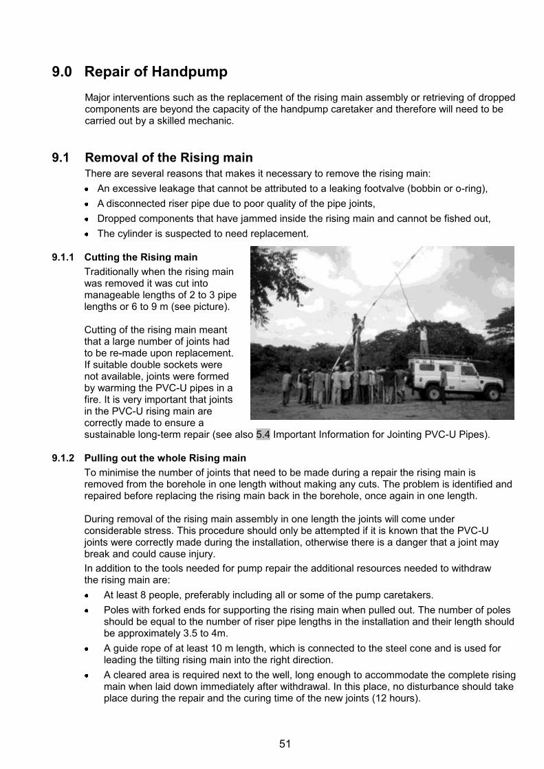
51
9.0 Repair of Handpump
Major interventions such as the replacement of the rising main assembly or retrieving of dropped components are beyond the capacity of the handpump caretaker and therefore will need to be carried out by a skilled mechanic.
9.1 Removal of the Rising main
There are several reasons that makes it necessary to remove the rising main: An excessive leakage that cannot be attributed to a leaking footvalve (bobbin or o-ring), A disconnected riser pipe due to poor quality of the pipe joints, Dropped components that have jammed inside the rising main and cannot be fished out, The cylinder is suspected to need replacement.
9.1.1 Cutting the Rising main
Traditionally when the rising main was removed it was cut into manageable lengths of 2 to 3 pipe lengths or 6 to 9 m (see picture).
Cutting of the rising main meant that a large number of joints had to be re-made upon replacement. If suitable double sockets were not available, joints were formed by warming the PVC-U pipes in a fire. It is very important that joints in the PVC-U rising main are correctly made to ensure a sustainable long-term repair (see also 5.4 Important Information for Jointing PVC-U Pipes).
9.1.2 Pulling out the whole Rising main
To minimise the number of joints that need to be made during a repair the rising main is removed from the borehole in one length without making any cuts. The problem is identified and repaired before replacing the rising main back in the borehole, once again in one length.
During removal of the rising main assembly in one length the joints will come under considerable stress. This procedure should only be attempted if it is known that the PVC-U joints were correctly made during the installation, otherwise there is a danger that a joint may break and could cause injury. In addition to the tools needed for pump repair the additional resources needed to withdraw the rising main are: At least 8 people, preferably including all or some of the pump caretakers. Poles with forked ends for supporting the rising main when pulled out. The number of poles
should be equal to the number of riser pipe lengths in the installation and their length should be approximately 3.5 to 4m.
A guide rope of at least 10 m length, which is connected to the steel cone and is used for leading the tilting rising main into the right direction.
A cleared area is required next to the well, long enough to accommodate the complete rising main when laid down immediately after withdrawal. In this place, no disturbance should take place during the repair and the curing time of the new joints (12 hours).
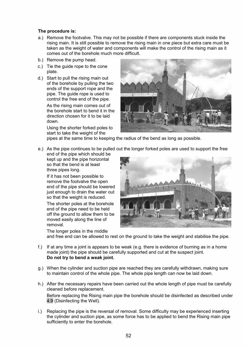
52
The procedure is: a.) Remove the footvalve. This may not be possible if there are components stuck inside the
rising main. It is still possible to remove the rising main in one piece but extra care must be taken as the weight of water and components will make the control of the rising main as it comes out of the borehole much more difficult.
b.) Remove the pump head. c.) Tie the guide rope to the cone
plate. d.) Start to pull the rising main out
of the borehole by pulling the two ends of the support rope and the pipe. The guide rope is used to control the free end of the pipe. As the rising main comes out of the borehole start to bend it in the direction chosen for it to be laid down. Using the shorter forked poles to start to take the weight of the pipes at the same time to keeping the radius of the bend as long as possible.
e.) As the pipe continues to be pulled out the longer forked poles are used to support the free
end of the pipe which should be kept up and the pipe horizontal so that the bend is at least three pipes long. If it has not been possible to remove the footvalve the open end of the pipe should be lowered just enough to drain the water out so that the weight is reduced. The shorter poles at the borehole end of the pipe need to be held off the ground to allow them to be moved easily along the line of removal. The longer poles in the middle and free end can be allowed to rest on the ground to take the weight and stabilise the pipe.
f.) If at any time a joint is appears to be weak (e.g. there is evidence of burning as in a home
made joint) the pipe should be carefully supported and cut at the suspect joint. Do not try to bend a weak joint.
g.) When the cylinder and suction pipe are reached they are carefully withdrawn, making sure
to maintain control of the whole pipe. The whole pipe length can now be laid down.
h.) After the necessary repairs have been carried out the whole length of pipe must be carefully cleaned before replacement. Before replacing the Rising main pipe the borehole should be disinfected as described under 4.9 (Disinfecting the Well).
i.) Replacing the pipe is the reversal of removal. Some difficulty may be experienced inserting
the cylinder and suction pipe, as some force has to be applied to bend the Rising main pipe sufficiently to enter the borehole.
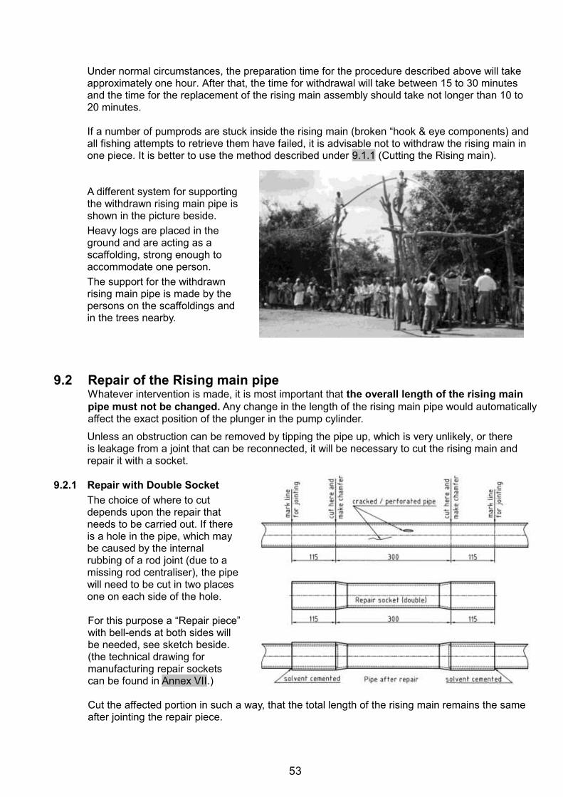
53
Under normal circumstances, the preparation time for the procedure described above will take approximately one hour. After that, the time for withdrawal will take between 15 to 30 minutes and the time for the replacement of the rising main assembly should take not longer than 10 to 20 minutes.
If a number of pumprods are stuck inside the rising main (broken “hook & eye components) and all fishing attempts to retrieve them have failed, it is advisable not to withdraw the rising main in one piece. It is better to use the method described under 9.1.1 (Cutting the Rising main).
A different system for supporting the withdrawn rising main pipe is shown in the picture beside. Heavy logs are placed in the ground and are acting as a scaffolding, strong enough to accommodate one person. The support for the withdrawn rising main pipe is made by the persons on the scaffoldings and in the trees nearby.
9.2 Repair of the Rising main pipe
Whatever intervention is made, it is most important that the overall length of the rising main pipe must not be changed. Any change in the length of the rising main pipe would automatically affect the exact position of the plunger in the pump cylinder.
Unless an obstruction can be removed by tipping the pipe up, which is very unlikely, or there is leakage from a joint that can be reconnected, it will be necessary to cut the rising main and repair it with a socket.
9.2.1 Repair with Double Socket
The choice of where to cut depends upon the repair that needs to be carried out. If there is a hole in the pipe, which may be caused by the internal rubbing of a rod joint (due to a missing rod centraliser), the pipe will need to be cut in two places one on each side of the hole.
For this purpose a “Repair piece” with bell-ends at both sides will be needed, see sketch beside. (the technical drawing for manufacturing repair sockets can be found in Annex VII.)
Cut the affected portion in such a way, that the total length of the rising main remains the same after jointing the repair piece.
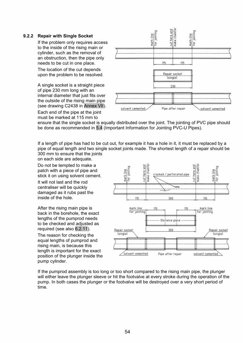
54
9.2.2 Repair with Single Socket
If the problem only requires access to the inside of the rising main or cylinder, such as the removal of an obstruction, then the pipe only needs to be cut in one place. The location of the cut depends upon the problem to be resolved.
A single socket is a straight piece of pipe 230 mm long with an internal diameter that just fits over the outside of the rising main pipe (see drawing C2438 in Annex VII). Each end of the pipe at the joint must be marked at 115 mm to ensure that the single socket is equally distributed over the joint. The jointing of PVC pipe should be done as recommended in 5.4 (Important Information for Jointing PVC-U Pipes).
If a length of pipe has had to be cut out, for example it has a hole in it, it must be replaced by a pipe of equal length and two single socket joints made. The shortest length of a repair should be 300 mm to ensure that the joints on each side are adequate. Do not be tempted to make a patch with a piece of pipe and stick it on using solvent cement. It will not last and the rod centraliser will be quickly damaged as it rubs past the inside of the hole.
After the rising main pipe is back in the borehole, the exact lengths of the pumprod needs to be checked and adjusted as required (see also 6.2.11). The reason for checking the equal lengths of pumprod and rising main, is because this length is important for the exact position of the plunger inside the pump cylinder.
If the pumprod assembly is too long or too short compared to the rising main pipe, the plunger will either leave the plunger sleeve or hit the footvalve at every stroke during the operation of the pump. In both cases the plunger or the footvalve will be destroyed over a very short period of time.
55
9.3 Fishing of Dropped Handpump Parts
During installation or maintenance activities, handpump components might fall into the well causing an obstruction, which immobilises the pump. Retrieving dropped components like a rising main from a Dug well is not a problem, whereas fishing of dropped parts in a casing pipe of a Borehole can be a difficult and time consuming task. In some cases, items inside the Rising main pipe may be extracted by removing the whole rising main and cutting it to gain access to the obstruction (as described under 9.1.1). In other cases something relatively simple can be made by the Area Mechanic to suit the object causing the obstruction. For example a “U-seal” that has rolled off the plunger and is left in the cylinder or rising main may be fished using a simple wire hook on a string. In the case of a “U-seal” left inside the rising main it is important not to try to fish the footvalve. If this is attempted the “U-seal” often causes the footvalve to jam inside the rising main pipe, making it necessary to remove the whole rising main assembly with the rods inside. Some ingenuity is required on the part of the Area Mechanic to deal with each situation as it arises.
A number of special tools “Fishing Tools” have been developed, in order to assist any fishing attempts of dropped handpump components. However, often these tools are not available or do not quite fit the problem at hand so more informal solutions need to be found. This mostly depends upon the ingenuity of the Area Mechanic.
The assembly drawings of the “Fishing tools” can be found in Annex VI. Detail drawings for manufacturing of the developed fishing tools are available on request.
10.0 Recording of Interventions
It is advisable to collect and record any data of a well, starting from digging or drilling, platform construction, installation of a handpump including all maintenance and repair interventions during the lifetime of the handpump and the well (like a “log-book” on a ship).
Besides Installation and Monitoring details, make the necessary entries of Maintenance and Repair in the documents of each pump. The information to be recorded will include date of breakdown, date of repair, nature of complaint, parts replaced and kind of repair or any other important observations. (see also “Examples for Recording of Interventions” in Annex V).

56
Annex I
Trouble Shooting Chart for AFRIDEV Handpumps
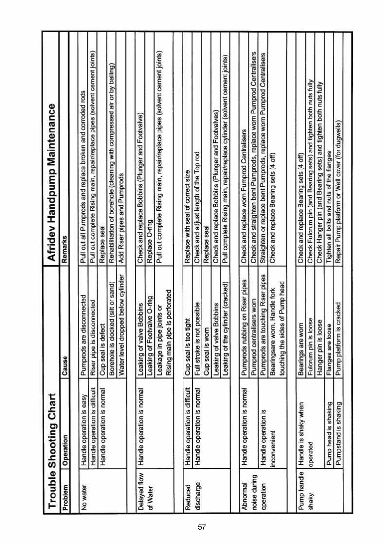
57

58
Annex II
List of Spare Parts for AFRIDEV Handpumps
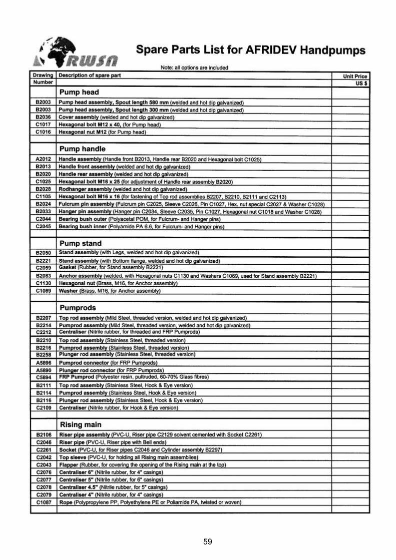
59
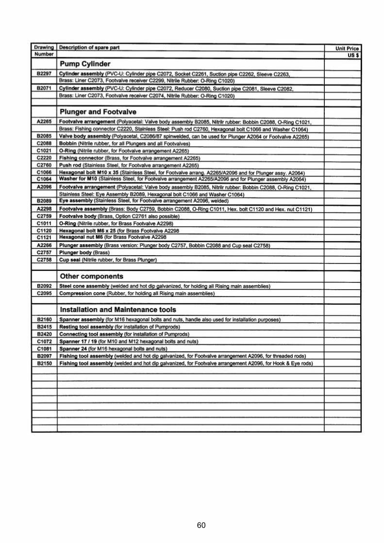
60
61
Annex III
Replacement Interval of AFRIDEV Wearing Parts
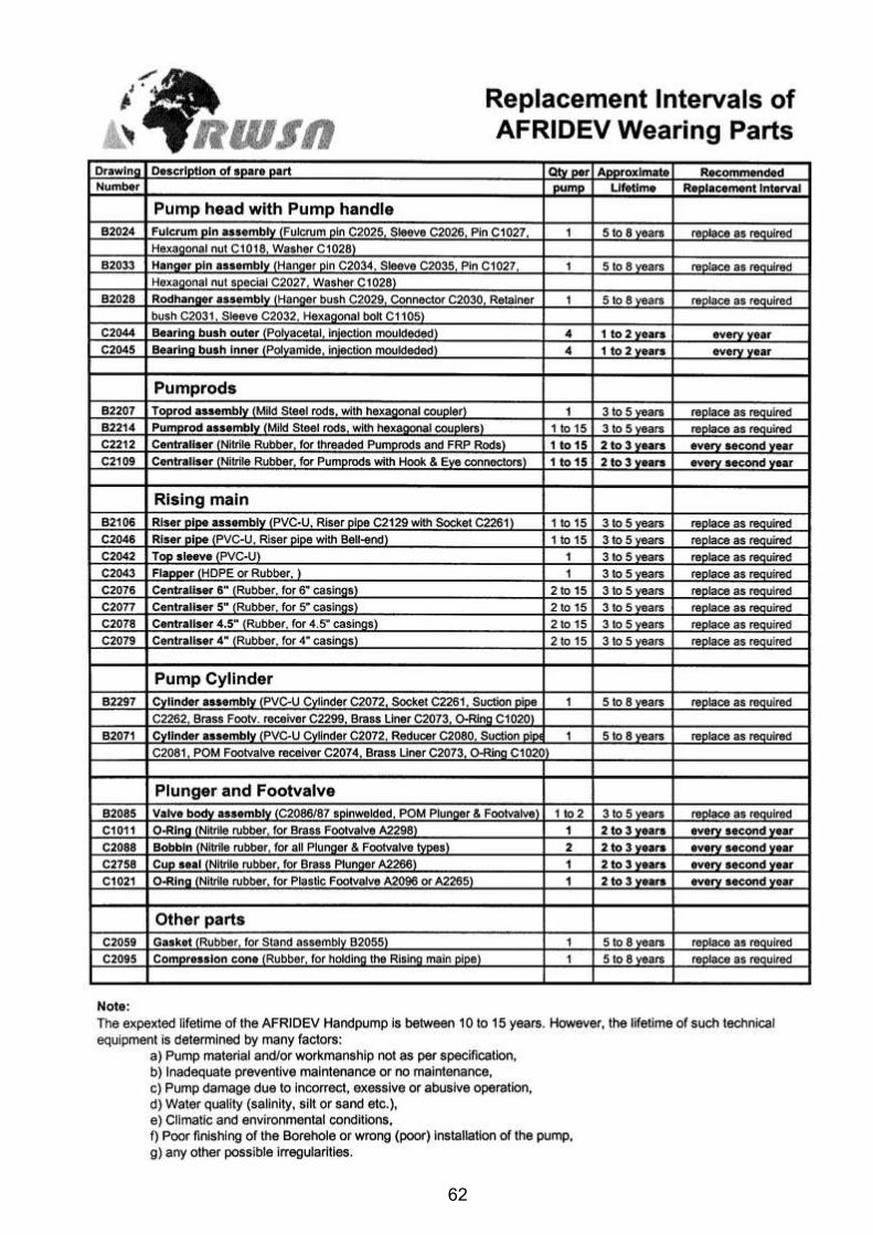
62

63
Annex IV
Correct Storage of AFRIDEV Handpump Components
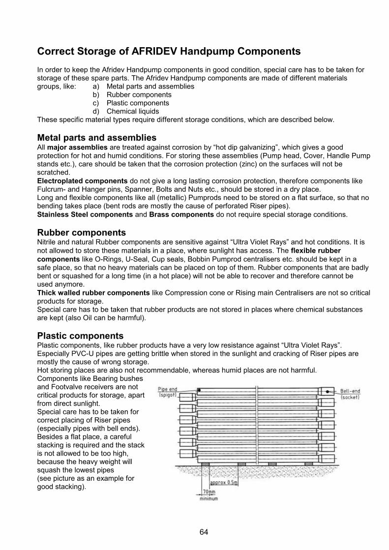
64
Correct Storage of AFRIDEV Handpump Components In order to keep the Afridev Handpump components in good condition, special care has to be taken for storage of these spare parts. The Afridev Handpump components are made of different materials groups, like: a) Metal parts and assemblies
b) Rubber components c) Plastic components d) Chemical liquids
These specific material types require different storage conditions, which are described below. Metal parts and assemblies All major assemblies are treated against corrosion by “hot dip galvanizing”, which gives a good protection for hot and humid conditions. For storing these assemblies (Pump head, Cover, Handle Pump stands etc.), care should be taken that the corrosion protection (zinc) on the surfaces will not be scratched. Electroplated components do not give a long lasting corrosion protection, therefore components like Fulcrum- and Hanger pins, Spanner, Bolts and Nuts etc., should be stored in a dry place. Long and flexible components like all (metallic) Pumprods need to be stored on a flat surface, so that no bending takes place (bent rods are mostly the cause of perforated Riser pipes). Stainless Steel components and Brass components do not require special storage conditions. Rubber components Nitrile and natural Rubber components are sensitive against “Ultra Violet Rays” and hot conditions. It is not allowed to store these materials in a place, where sunlight has access. The flexible rubber components like O-Rings, U-Seal, Cup seals, Bobbin Pumprod centralisers etc. should be kept in a safe place, so that no heavy materials can be placed on top of them. Rubber components that are badly bent or squashed for a long time (in a hot place) will not be able to recover and therefore cannot be used anymore. Thick walled rubber components like Compression cone or Rising main Centralisers are not so critical products for storage. Special care has to be taken that rubber products are not stored in places where chemical substances are kept (also Oil can be harmful). Plastic components Plastic components, like rubber products have a very low resistance against “Ultra Violet Rays”. Especially PVC-U pipes are getting brittle when stored in the sunlight and cracking of Riser pipes are mostly the cause of wrong storage. Hot storing places are also not recommendable, whereas humid places are not harmful. Components like Bearing bushes and Footvalve receivers are not critical products for storage, apart from direct sunlight. Special care has to be taken for correct placing of Riser pipes (especially pipes with bell ends). Besides a flat place, a careful stacking is required and the stack is not allowed to be too high, because the heavy weight will squash the lowest pipes (see picture as an example for good stacking).
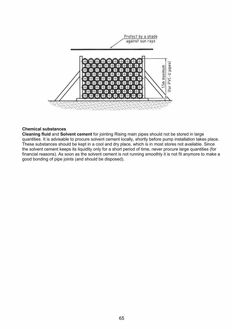
65
Chemical substances Cleaning fluid and Solvent cement for jointing Rising main pipes should not be stored in large quantities. It is advisable to procure solvent cement locally, shortly before pump installation takes place. These substances should be kept in a cool and dry place, which is in most stores not available. Since the solvent cement keeps its liquidity only for a short period of time, never procure large quantities (for financial reasons). As soon as the solvent cement is not running smoothly it is not fit anymore to make a good bonding of pipe joints (and should be disposed).
66
Annex V
Examples for Recording of Interventions
a) Installation Card b) Maintenance Card c) Monitoring Card

67
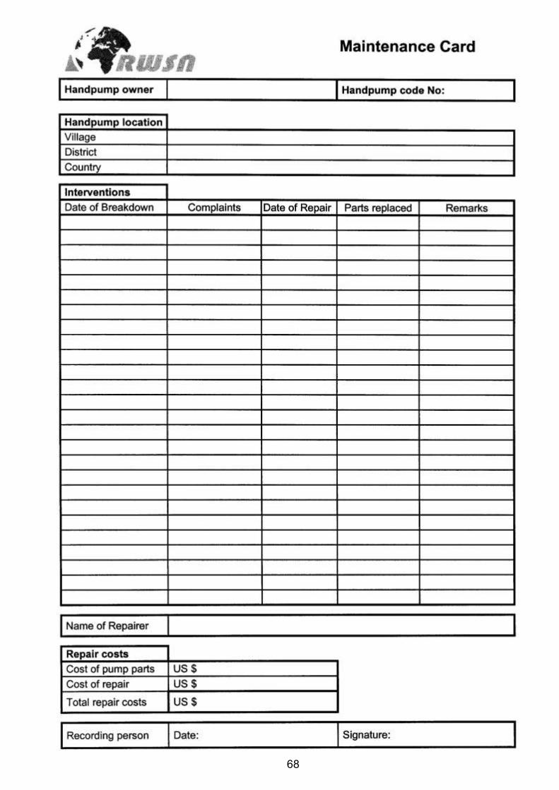
68
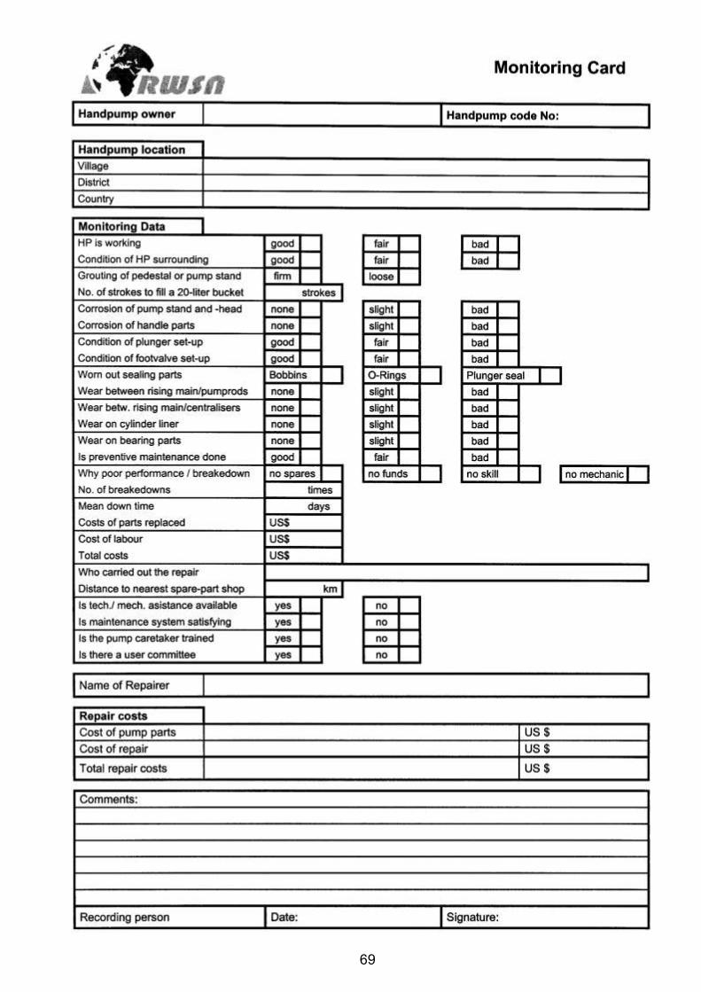
69
70
Annex VI
Drawings of Fishing Tools for dropped Handpump Parts
a) For Fishing disconnected Pumprods b) For Fishing broken Pumprods c) For Fishing disconnected or broken Riser Pipes
Please note: for all detail drawings please contact SKAT (see address on first page).
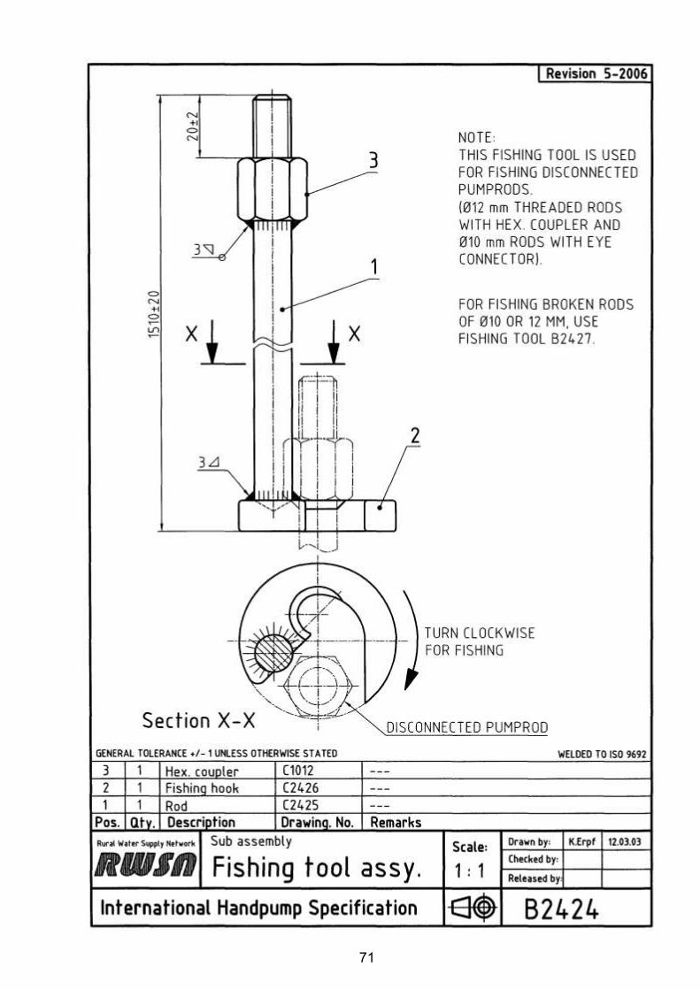
71
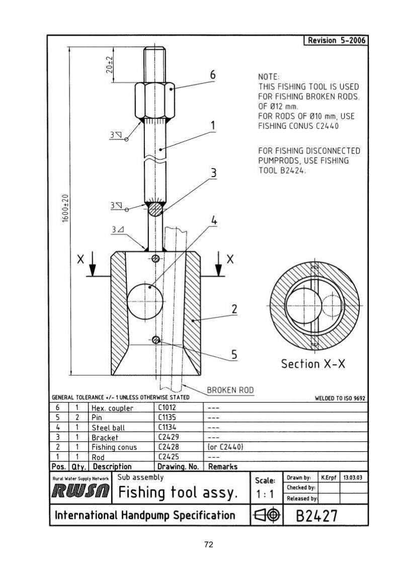
72
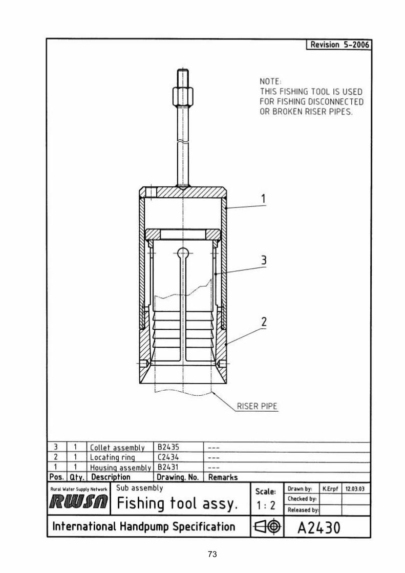
73
74
Annex VII
Technical Drawings of Repair Sockets
d) Repair socket C2438 (straight socket), e) Repair socket C2439 (socket with bell-ends)

75
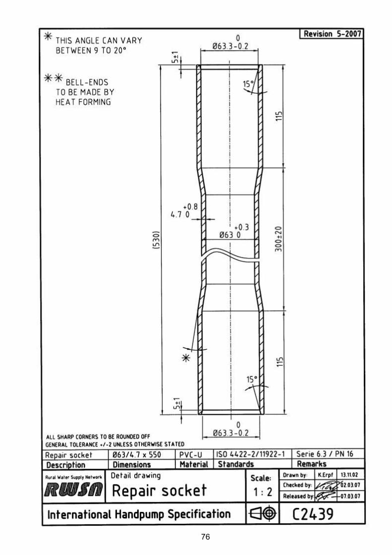
76

Appendix G
Drilling Contract
EWB – Hope College Bondo Community, Well Install
Page 1 of 7
REQUEST FOR QUOTE
Engineers Without Borders Hope College, EWB-Hope, (Engineer) requests a quotation from Mr. Melchizedeck of (Contractor) for the completion of well installation activities within the community of Bondo, Kenya (herein referenced as the Site). 1. CONTRACTOR’S QUOTE FOR SERVICES Please submit a completed quote to Mr. Adam of EWB-Hope via email ([email protected]) by April XX, 2016. Please complete the bid table at the end of this document to provide unit rates, material costs, and an anticipated schedule for all tasks described. Any questions related to this RFQ shall be addressed to Mr. Adam of Hope-EWB via email ([email protected]). 2. PROJECT INFORMATION The proposed well site is located within the community of Bondo, Kenya (Latitude: -1.106052° Longitude: 34.377193°). See Drawings D-1, D-2, and D-3 on the attached drawing set for site location maps. The Contractor is responsible for pulling all necessary well installation permits and abiding to all local well construction codes. The Contractor is responsible for providing all materials and equipment for the installation and construction activities related to the details outlined in this document. The well installation tasks to be completed are summarized below:
Task 1. Arrange all necessary well construction permits
Task 2. Complete one deep boring (50-100 meters, TBD) and install well
Task 3. Complete well testing activities including well development, pump testing, and water quality testing
Task 4. Install well pad at well head
Task 5. Install Afridev hand pump
Task 6. Transport and supply cement bags to EWB-Hope
Task 7. Provide 3 Years of support to community on maintenance of pump and well
EWB – Hope College Bondo Community, Well Install
Page 2 of 7
Details on each of these tasks are outlined in the following sections and in the attached drawing set, Drawings D-1through D-6. 3. PROJECT SCHEDULE The project work described in this document shall be completed by the Contractor. The anticipated start date of the well installation activities is August 2nd, 2016. The exact start date of the work will be confirmed between the Engineer and Contractor a minimum of 4 weeks prior to the start of work. The Engineer requests that the Contractor completes all work within a 14 day schedule. 4. PROJECT SPECIFICS Task 1 – Arrange all necessary well construction permits The Contractor shall be responsible for arranging all necessary well permits two weeks prior to beginning site work. The Contractor is responsible for all fees related to pulling and satisfying the permit throughout the well construction process. The Contractor must provide notice to the Engineer of successfully pulling the permit a minimum of two weeks prior to the start date of the drilling activities. Task 2 - Installation of borehole and deep well The Contractor shall install one deep well. The screen intervals shall be set from approximately XX (TBD) to 50-100 (TBD) meters below ground surface (bgs). The boring for the well shall be completed using an air rotary drill rig with a minimum of an 8-inch (20-cm) drill bit. Exact (final) depths of the monitoring well will be verified in the field by the Engineer based on lithology and presence of water. The Contractor shall remove drill cuttings from the well location to keep a clean work area. See Drawing D-3 for the proposed well location. The well will be installed to meet the Engineer’s specifications. The Contractor shall be responsible for providing all equipment and products necessary to install the well. All materials and equipment shall be staged at the Site before starting the installation of the boring. Specifications of the well design are outlined on Drawing D-4 and are outlined below:
- The well screens are to be 6 inch diameter polyvinyl chloride (PVC) screens with a slot size of 1 mm and a slot spacing of XX (TBD) mm.
- Casing centralizers are to be placed at the top and bottom of each screened section. Rubber casing centralizers have been specified for this project.
- The well casing is to be constructed of heavy duty PVC.
- A sand filter pack shall be placed from the total boring depth to approximately 0.5 meters above the top of each well screened interval. The filter pack materials shall
EWB – Hope College Bondo Community, Well Install
Page 3 of 7
have an effective grainsize of 2 millimeters. A substitute filter pack must be approved by the Engineer prior to use.
- A neat cement (cement/water) slurry shall be installed in the annular space above the filter pack up, and to the ground surface. The annular seal shall be completed to the water table, or no less than 10 meters below ground surface, whichever is deeper.
Any deviations from these specifications and those provided in Drawing D-4 must be approved by the Engineer before installation. If the Contractor proposes different construction methods then the ones listed, they must outline any changes on the attached bid form. Task 3 – Well testing activities Well Development Following well installation, the Contractor shall develop the new well using air lifting techniques. A minimum of three well volumes of water shall be removed during development (estimated approx. 7500 liters). The Engineer will be onsite to observe and determine when well development is complete. Development water may be discharged on the ground, but the Contractor shall provide enough hose to direct development water away from the well head work area. Well Pump Testing Following well development, the Contractor shall assist the Engineer in the completion of a step-drawdown pump test and a constant rate pump test. Approximately 6 hours shall be allotted for the step drawdown test and 24 hours allotted for the constant rate pumping test. The Contractor shall provide oversight throughout the night of the constant rate pump test. For the completion of these tests the Contractor must supply the following equipment:
- 100 meter water level indicator (to measure depth to water table) - Down-well electric pump with conveyance pipe to discharge water. Pumping rates
required for step and constant rate test are between 7 and 35 liters per minute - Power supply to run electric pump - Valve to control pumping flow rate at discharge - Bucket for verifying flow rate
Water Quality Testing During the pump test, the Contractor is to collect a water sample from the well to assess water quality. The water sample is to be submitted to a laboratory of the Contractor’s choosing and at a minimum be sampled for the parameters listed below. The Contractor is to supply the Engineer with a copy of the laboratory results for the water test within one week of testing.
- E.coli Coliform, Rapid (total) Coliform
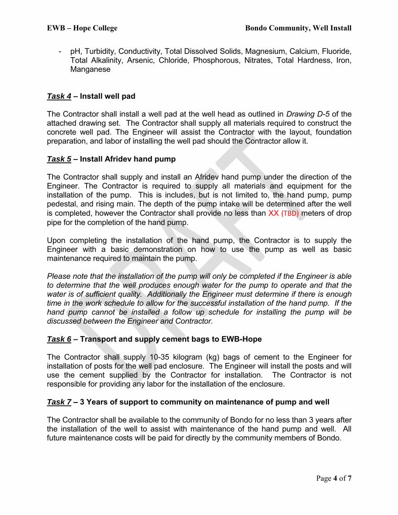
EWB – Hope College Bondo Community, Well Install
Page 4 of 7
- pH, Turbidity, Conductivity, Total Dissolved Solids, Magnesium, Calcium, Fluoride, Total Alkalinity, Arsenic, Chloride, Phosphorous, Nitrates, Total Hardness, Iron, Manganese
Task 4 – Install well pad The Contractor shall install a well pad at the well head as outlined in Drawing D-5 of the attached drawing set. The Contractor shall supply all materials required to construct the concrete well pad. The Engineer will assist the Contractor with the layout, foundation preparation, and labor of installing the well pad should the Contractor allow it. Task 5 – Install Afridev hand pump The Contractor shall supply and install an Afridev hand pump under the direction of the Engineer. The Contractor is required to supply all materials and equipment for the installation of the pump. This is includes, but is not limited to, the hand pump, pump pedestal, and rising main. The depth of the pump intake will be determined after the well is completed, however the Contractor shall provide no less than XX (TBD) meters of drop pipe for the completion of the hand pump. Upon completing the installation of the hand pump, the Contractor is to supply the Engineer with a basic demonstration on how to use the pump as well as basic maintenance required to maintain the pump. Please note that the installation of the pump will only be completed if the Engineer is able to determine that the well produces enough water for the pump to operate and that the water is of sufficient quality. Additionally the Engineer must determine if there is enough time in the work schedule to allow for the successful installation of the hand pump. If the hand pump cannot be installed a follow up schedule for installing the pump will be discussed between the Engineer and Contractor. Task 6 – Transport and supply cement bags to EWB-Hope The Contractor shall supply 10-35 kilogram (kg) bags of cement to the Engineer for installation of posts for the well pad enclosure. The Engineer will install the posts and will use the cement supplied by the Contractor for installation. The Contractor is not responsible for providing any labor for the installation of the enclosure. Task 7 – 3 Years of support to community on maintenance of pump and well The Contractor shall be available to the community of Bondo for no less than 3 years after the installation of the well to assist with maintenance of the hand pump and well. All future maintenance costs will be paid for directly by the community members of Bondo.
EWB – Hope College Bondo Community, Well Install
Page 5 of 7
5. SITE SPECIFIC NOTES
The groundwater table is encountered 3.25 meters below ground surface. Site geology generally consists of weathered volcanic tuff/laterite overlaying volcanic rock.
The Contractor is responsible for providing an adequate supply of water for all site activities. Water will not be readily available at the site.
The Contractor shall decontaminate drilling tools prior to starting work to prevent contamination of the constructed well.
If the boring/well does not meet the depth, alignment, plumbness, or other requirements in the opinion of the Engineer, the borehole will be considered an abandoned boring. Should this occur, the Contractor shall immediately start a boring in the vicinity at a location designated by the Engineer. The abandoned boring shall be backfilled and sealed with a bentonite slurry.
The Contractor shall minimize impact on the property by maintaining a clean work site every workday. Immediately after drilling activities are complete, the entire work area shall be returned to conditions equal to or exceeding the conditions encountered upon start of the project.
Upon completion of site activities, the Contractor is responsible for preparing a detailed drilling report for the Engineer. This report shall include: well construction log, total depth drilled, geologic records from the boring, a summary of quantities of materials used to construct the well, pump test data, and water quality testing data.
6. TYPE OF CONTRACT
Contractor shall execute a contract with the Engineer (EWB-Hope) for the unit sum cost price per the project description. The attached Bid Table will be included in the contract to outline the costs of the project. The Contractor will only be paid for the services provided.
7. INVOICING
It is understood that in order for the Engineer (EWB-Hope) to issue a final payment, a detailed invoice must be submitted upon project completion. This invoice shall cite specific charges for quantities at unit cost. Invoice shall resemble bid form with specific charges to each line item.
EWB – Hope College Bondo Community, Well Install
Page 6 of 7
If you have any questions, or need additional information, please do not hesitate to contact me at [email protected]. Sincerely, Adam Contact Info Attachments: Contractors Bid Table Drawing Set
D-1 SITE LOCATION AND INDEX D-2 BONDO COMMUNITY POINTS OF INTEREST D-3 PROJECT SITE PLAN D-4 WELL DETAIL D-5 WELL PAD DETAIL D-6 WELL PAD ENCLOSURE DETAIL
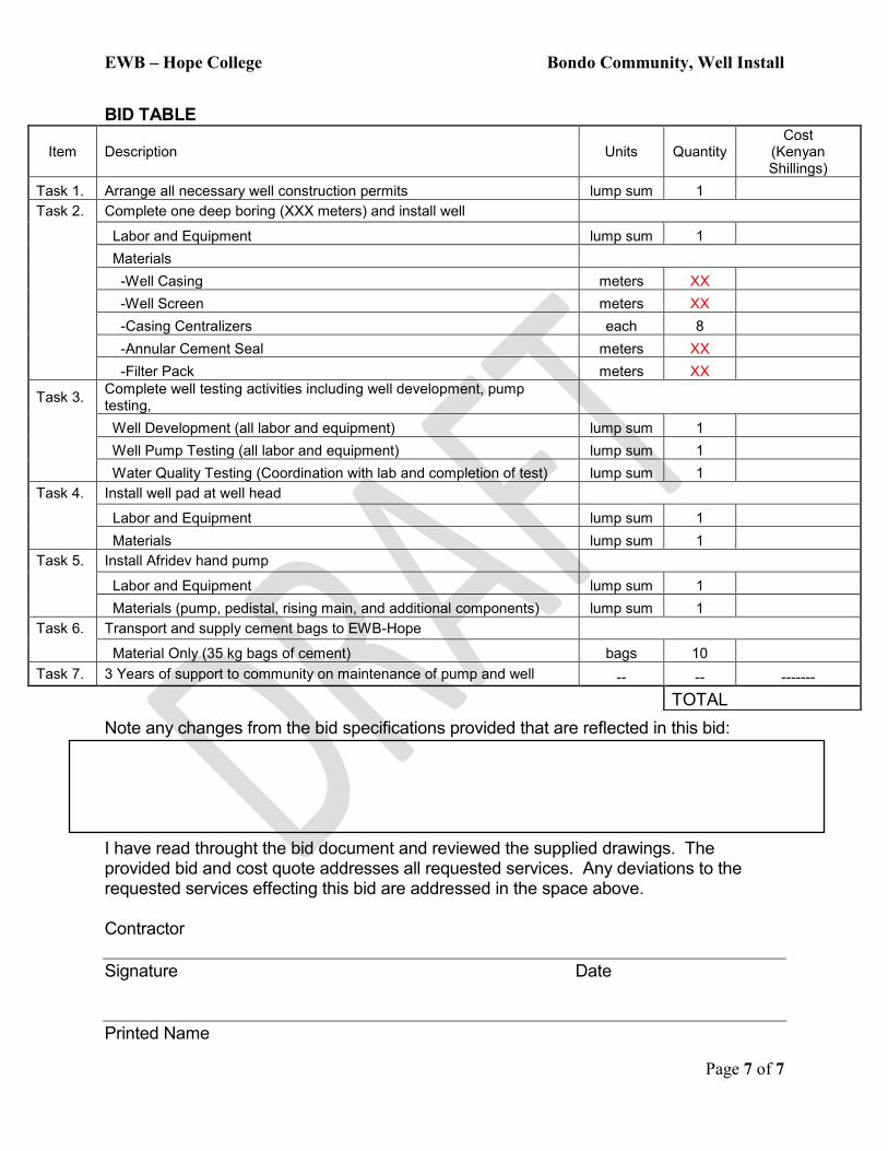
EWB – Hope College Bondo Community, Well Install
Page 7 of 7
BID TABLE
Note any changes from the bid specifications provided that are reflected in this bid: I have read throught the bid document and reviewed the supplied drawings. The provided bid and cost quote addresses all requested services. Any deviations to the requested services effecting this bid are addressed in the space above. Contractor Signature Date Printed Name
Item Description Units Quantity Cost
(Kenyan Shillings)
Task 1. Arrange all necessary well construction permits lump sum 1 Task 2. Complete one deep boring (XXX meters) and install well
Labor and Equipment lump sum 1 Materials
-Well Casing meters XX -Well Screen meters XX -Casing Centralizers each 8 -Annular Cement Seal meters XX -Filter Pack meters XX
Task 3. Complete well testing activities including well development, pump testing,
Well Development (all labor and equipment) lump sum 1 Well Pump Testing (all labor and equipment) lump sum 1 Water Quality Testing (Coordination with lab and completion of test) lump sum 1
Task 4. Install well pad at well head
Labor and Equipment lump sum 1
Materials lump sum 1 Task 5. Install Afridev hand pump
Labor and Equipment lump sum 1 Materials (pump, pedistal, rising main, and additional components) lump sum 1 Task 6. Transport and supply cement bags to EWB-Hope
Material Only (35 kg bags of cement) bags 10 Task 7. 3 Years of support to community on maintenance of pump and well -- -- -------
TOTAL