Embed Size (px)
Citation preview

58 59DKMH.PK.130.B4.02 520L0407 Rev. C 04.2004 DKMH.PK.130.B4.02 520L0407 Rev. C 04.2004
VERSIONS
OMVTechnical InformationVersions
Mo
un
tin
g fl
ang
e
Shaf
t
Po
rt s
ize
Euro
pea
n v
ersi
on
US
vers
ion
Dra
in c
on
nec
tio
n
Ch
eck
valv
e
Mai
n t
ype
des
ign
atio
n
Features available (options) : Speed sensorMotor with tacho connectionViton shaft sealPaintedUltra short
Cyl. 50 mm G1 m Yes Yes OMV
Cyl. 2.25 in 1 5/16-12 UN m Yes Yes OMV
Splined 2.125 in
G1 m Yes Yes OMV Standard
1 5/16-12 UN m Yes Yes OMVflange
Tapered 60 mm G1 m Yes Yes OMV
Tapered 2.25 in 1 5/16-12 UN m Yes Yes OMV
SAE-C Cyl. 2.25 in 1 5/16-12 UN m Yes Yes OMV
flange Splined 2.125 in 1 5/16-12 UN m Yes Yes OMV
Cyl. 50 mm G1 m Yes Yes OMVW
Wheel Tapered 60 mm G1 m Yes Yes OMVW
Tapered 2.25 in 1 5/16-12 UN m Yes Yes OMVW
Short No output shaft G1 m Yes Yes OMVS
Function diagram - see page : →

58 59DKMH.PK.130.B4.02 520L0407 Rev. C 04.2004 DKMH.PK.130.B4.02 520L0407 Rev. C 04.2004
CO
DE
NU
MB
ER
Tech
nic
al d
ata
– P
age
Per
mis
sib
le s
haf
t lo
ads
Dim
ensi
on
s –
Pag
e
Displacement [cm3]
315 400 500 630 800151B 3100 3101 3102 3103 3104 60 63 72
151B 2150 2151 2152 2153 2154 60 63 73
151B 3105 3106 3107 3108 3109 60 63 72
151B 2155 2156 2157 2158 2159 60 63 73
151B 3110 3111 3112 3113 3114 60 63 72
151B 2160 2161 2162 2163 2164 60 63 73
151B 2183 2184 2185 2186 2187 60 64 74
151B 2188 2189 2190 2191 2192 60 64 74
151B 3115 3116 3117 3118 3119 60 63 75
151B 3120 3121 3122 3123 3124 60 63 75
151B 2170 2171 2172 2173 2174 60 63 76
151B 3125 3126 3127 3128 3129 60 – 77
65 65 66 66 67
CODE NUMBERS
OMVTechnical InformationCode Numbers
OrderingAdd the four digit prefix “151B” to the four digit numbers from the chart for complete code number.
Example: 151B3101 for an OMV 400 with standard flange, cyl. 50 mm shaft and port size G 1.
Note: Orders will not be accepted without the four digit prefix.
CO
DE
NU
MB
ERS
Tech
nic
al d
ata
– P
age
Shaf
t lo
ads
– P
age
Dim
ensi
on
s –
Pag
e

60 61DKMH.PK.130.B4.02 520L0407 Rev. C 04.2004 DKMH.PK.130.B4.02 520L0407 Rev. C 04.2004
Type Max. inlet pressure Max. return pressure
with drain line bar
cont. 210 140
OMV [psi] [3050] [2030]
OMVW bar
int.1) 250 175
[psi] [3630] [2540] OMVS
bar peak2)
300 210
[psi] [4350] [3050]
1) Intermittent operation: the permissible values may occur for max. 10% of every minute. 2) Peak load: The permissible values may occur for max. 1% of every minute.
For max. permissible combination of flow and pressure, see function diagram for actual motor.
TECHNICAL DATA FOR OMV, OMVW AND OMVS
OMVTechnical InformationTechnical data
Type OMV OMV OMV OMV OMV OMVW OMVW OMVW OMVW OMVW OMVS OMVS OMVS OMVS OMVS Motor size 315 400 500 630 800
Geometric displacement cm3 314.5 400.9 499.6 629.1 801.8
[in3] [19.19] [24.46] [30.49] [38.39] [48.93]
Max. speed min-1 cont. 510 500 400 315 250
[rpm] int1) 630 600 480 380 300
cont.
920 1180 1460 1660 1880
Max. torque Nm [8140] [10440] [12920] [14690] [16640]
[lbf·in]
int.1) 1110 1410 1760 1940 2110
[9820] [12480] [15580] [17170] [18680]
cont.
42.5 53.5 53.5 48.0 42.5
Max. output kW [57.0] [71.7] [71.7] [64.4] [57.0]
[hp] int.1)
51.0 64.0 64.0 56.0 48.0
[68.4] [85.8] [85.8] [75.1] [64.4]
cont.
200 200 200 180 160
[2900] [2900] [2900] [2610] [2320]
Max. pressure drop bar
int.1) 240 240 240 210 180
[psi] [3480] [3480] [3480] [3050] [2610]
peak2)
280 280 280 240 210
[4060] [4060] [4060] [3480] [3050]
Max. oil flow
cont.
160 200 200 200 200
l/min [42.3] [52.8] [52.8] [52.8] [52.8]
[USgal/min] int.1)
200 240 240 240 240
[52.8] [63.4] [63.4] [63.4] [63.4]
Max. starting pressure bar 8 8 8 8 8
with unloaded shaft [psi] [116] [116] [116] [116] [116]
at max. press. drop cont. 710 910 1130 1330 1510
Min. starting Nm [lbf·in] [6280] [8050] [10000] [11770] [13360]
torque at max. press. drop int.1) 850 1090 1360 1550 1700
Nm [lbf·in] [7520] [9650] [12040] [13720] [15050]

60 61DKMH.PK.130.B4.02 520L0407 Rev. C 04.2004 DKMH.PK.130.B4.02 520L0407 Rev. C 04.2004
OMVTechnical InformationTechnical data
MAX. PERMISSIBLE SHAFT SEAL PRESSURE
OMV with check valves OMV with check valves and without use of and with drain connection: drain connection: The pressure on the shaft seal The shaft seal pressure equals never exceeds the pressure in the pressure on the drain line. the return line
Max. return pressure without drain line or max. pressure in the drain line
– – – – Intermittent operation: the permissible values may occur for max. 10% of every minute.
Continuous operation

62 63DKMH.PK.130.B4.02 520L0407 Rev. C 04.2004 DKMH.PK.130.B4.02 520L0407 Rev. C 04.2004
OMVTechnical InformationTechnical data
PRESSURE DROP IN MOTOR
OIL FLOW IN DRAIN LINE
DIRECTION OF SHAFT ROTATION
The curve applies to an unloaded motor shaft and an oil viscosity of 35 mm2/s (165 SUS)
The table shows the max. oil flow in the drain line at a return pressure less than 5-10 bar [75-150 psi].
Pressure Viscosity Oil flow in drop drain line bar mm2/s l/min [psi] [SUS] [US gal/min]
140
20 3.0
[100] [0.79]
[2030] 35 2.0
[165] [0.53]
210
20 6.0
[100] [1.59]
[3050] 35 4.0
[165] [1.06]
62 63DKMH.PK.130.B4.02 520L0407 Rev. C 04.2004 DKMH.PK.130.B4.02 520L0407 Rev. C 04.2004
OMVTechnical InformationTechnical data
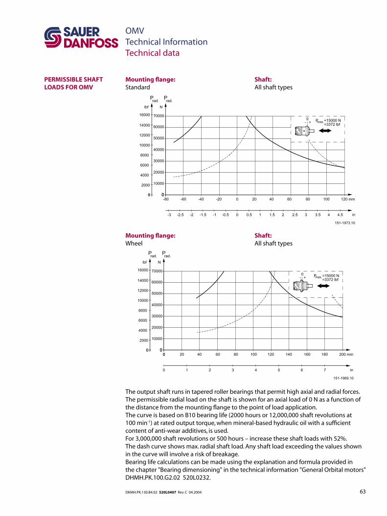
PERMISSIBLE SHAFT LOADS FOR OMV
Mounting flange: Shaft:Standard All shaft types
Mounting flange: Shaft: Wheel All shaft types
The output shaft runs in tapered roller bearings that permit high axial and radial forces.The permissible radial load on the shaft is shown for an axial load of 0 N as a function of the distance from the mounting flange to the point of load application.The curve is based on B10 bearing life (2000 hours or 12,000,000 shaft revolutions at 100 min-1) at rated output torque, when mineral-based hydraulic oil with a sufficient content of anti-wear additives, is used.For 3,000,000 shaft revolutions or 500 hours – increase these shaft loads with 52%.The dash curve shows max. radial shaft load. Any shaft load exceeding the values shown in the curve will involve a risk of breakage.Bearing life calculations can be made using the explanation and formula provided in the chapter "Bearing dimensioning" in the technical information "General Orbital motors" DHMH.PK.100.G2.02 520L0232.

64 65DKMH.PK.130.B4.02 520L0407 Rev. C 04.2004 DKMH.PK.130.B4.02 520L0407 Rev. C 04.2004
OMVTechnical InformationTechnical data
PERMISSIBLE SHAFT LOADS FOR OMV
Mounting flange: Shaft:SAE-C All shaft types
A: Cyl. 2.25 in shaftB: Splined 2.125 in shaft
The output shaft runs in tapered roller bearings that permit high axial and radial forces.The permissible radial load on the shaft is shown for an axial load of 0 N as a function of the distance from the mounting flange to the point of load application.The curve is based on B10 bearing life (2000 hours or 12,000,000 shaft revolutions at 100 min-1) at rated output torque, when mineral-based hydraulic oil with a sufficient content of anti-wear additives, is used.For 3,000,000 shaft revolutions or 500 hours – increase these shaft loads with 52%.The dash curve shows max. radial shaft load. Any shaft load exceeding the values shown in the curve will involve a risk of breakage.Bearing life calculations can be made using the explanation and formula provided in the chapter "Bearing dimensioning" in the technical information "General Orbital motors" DHMH.PK.100.G2.02 520L0232.

64 65DKMH.PK.130.B4.02 520L0407 Rev. C 04.2004 DKMH.PK.130.B4.02 520L0407 Rev. C 04.2004
Explanation of function diagram use, basis and conditions can be found on page 5.n Continuous rangen Intermittent range (max. 10% operation every minute)
Note: Intermittent pressure drop and oil flow must not occur simultaneously.
FUNCTION DIAGRAMS
OMVTechnical InformationFunction diagrams

66 67DKMH.PK.130.B4.02 520L0407 Rev. C 04.2004 DKMH.PK.130.B4.02 520L0407 Rev. C 04.2004
Explanation of function diagram use, basis and conditions can be found on page 5.n Continuous rangen Intermittent range (max. 10% operation every minute)
Note: Intermittent pressure drop and oil flow must not occur simultaneously.
FUNCTION DIAGRAMS
OMVTechnical InformationFunction diagrams

68 69DKMH.PK.130.B4.02 520L0407 Rev. C 04.2004 DKMH.PK.130.B4.02 520L0407 Rev. C 04.2004
OMVTechnical InformationShaft version
SHAFT VERSION
A: Cylindrical 50 mm shaftD: Parallel key A14 × 9 × 70 DIN 6885 Keyway deviates from standard
B: Cylindrical 2.25 in shaft for OMV with standard mounting flangeE: Parallel key 1/2 × 1/2 × 21/4 in B.S. 46 Keyway deviates from standard
C: Cylindrical 2.25 in shaft for OMV with mounting flange SAE-CF: Parallel key 1/2 × 1/2 × 21/4 in B.S. 46 Keyway deviates from standard

68 69DKMH.PK.130.B4.02 520L0407 Rev. C 04.2004 DKMH.PK.130.B4.02 520L0407 Rev. C 04.2004
OMVTechnical InformationShaft version
SHAFT VERSION
D: Involute splined shaft ANS B92.1 - 1970 standard Flat root side fit Pitch 8/16
Teeth 16 Major dia. 2.125 in Pressure angle 30°
US VersionE: Involute splined shaft for OMV with standard mounting flange ANS B92.1 - 1970 standard Flat root side fit Pitch 8/16
Teeth 16 Major dia. 2.125 in Pressure angle 30°
US VersionF: Involute splined shaft for OMV with mounting flange SAE-C ANS B92.1 - 1970 standard Flat root side fit Pitch 8/16
Teeth 16 Major dia. 2.125 in Pressure angle 30°

70 71DKMH.PK.130.B4.02 520L0407 Rev. C 04.2004 DKMH.PK.130.B4.02 520L0407 Rev. C 04.2004
OMVTechnical InformationShaft version
SHAFT VERSION
G: Tapered 60 mm shaft (ISO/R775)J: DIN 937 Across flats: 65 mm Tightening torque: 750 ±50 Nm [6640 ±440 lbf·in]I: Taper 1:10K: Parallel key B16 × 10 × 32 DIN 6885 Keyway deviates from standard
H: Tapered 2.25 in shaftL: Cone 1:8 SAE J501M: 11/2 - 18 UNEF Across flats: 23/8 in Tightening torque: 750 ±50 Nm [6640 ±440 lbf·in]N: Parallel key 9/16 × 9/16 × 2 in B.S. 46 Keyway deviates from standard

70 71DKMH.PK.130.B4.02 520L0407 Rev. C 04.2004 DKMH.PK.130.B4.02 520L0407 Rev. C 04.2004
A: G main ports B: UN main ports E: ISO 228/1 - G1 F: 1 5/16 - 12 UN O-ring boss port
C: G drain port D: UNF drain port G: ISO 228/1 - G1/4 H: 9/16 - 18 UNF O-ring boss port
OMVTechnical InformationTechnical data
PORT THREAD VERSIONS

72 73DKMH.PK.130.B4.02 520L0407 Rev. C 04.2004 DKMH.PK.130.B4.02 520L0407 Rev. C 04.2004
OMVTechnical InformationDimensions – European version
STANDARD FLANGE
Lmax.
L1*
L2
Type mm mm mm [in] [in] [in]
OMV 315 215 22.0 160
[8.46] [0.866] [6.30]
OMV 400 222 29.0 167
[8.74] [1.142] [6.57]
OMV 500 230 37.0 175
[9.05] [1.457] [6.89]
OMV 630 240 47.5 186
[9.45] [1.870] [7.32]
OMV 800 254 61.5 200
[10.00] [2.421] [7.87]
L3
Output shaft mm [in]Cyl. 50 mm 82
Splined 2.125 in [3.23]
Tapered 60 mm 105
[4.13]
C: Drain connection G 1⁄4; 12 mm [0.47 in] deepD: M12; 12 mm [0.47 in] deep E: G 1; 18 mm [0.71 in] deep
*) The gearwheel set is 3.5 mm [0.138 in] wider across the rollers than the L
1 dimensions

72 73DKMH.PK.130.B4.02 520L0407 Rev. C 04.2004 DKMH.PK.130.B4.02 520L0407 Rev. C 04.2004
OMVTechnical InformationDimensions – US version
STANDARD FLANGE
Lmax.
L1*
L2
Type mm mm mm [in] [in] [in]
OMV 315 215 22.0 160
[8.46] [0.866] [6.30]
OMV 400 222 29.0 167
[8.74] [1.142] [6.57]
OMV 500 230 37.0 175
[9.05] [1.457] [6.89]
OMV 630 240 47.5 186
[9.45] [1.870] [7.32]
OMV 800 254 61.5 200
[10.00] [2.421] [7.87]
L3
Output shaft mm [in]Cyl. 2.25 in 82
Splined 2.125 in [3.23]
Tapered 2.25 in 100
[3.94]
C: Drain connection 9⁄16 - 18 UNF; 13 mm [0.51 in] deep O-ring boss portD: 1 5⁄16 - 12 UN; 19 mm [0.75 in] deep O-ring boss port*) The gearwheel set is 3.5 mm [0.138 in] wider across the rollers than the L
1 dimensions

74 75DKMH.PK.130.B4.02 520L0407 Rev. C 04.2004 DKMH.PK.130.B4.02 520L0407 Rev. C 04.2004
OMVTechnical InformationDimensions – US version
SAE-C FLANGE
Lmax.
L1*
L2
Type mm mm mm [in] [in] [in]
OMV 315 239 22.0 185
[9.41] [0.866] [7.28]
OMV 400 246 29.0 192
[9.69] [1.142] [7.56]
OMV 500 254 37.0 200
[10.00] [1.457] [7.87]
OMV 630 265 47.5 211
[10.43] [1.870] [8.31]
OMV 800 279 61.5 225
[10.98] [2.421] [8.86]
L3
Output shaft mm [in]
Cyl. 2.25 in 99
[3.90]
Splined 2.125 in 76.7
[3.02]
C: Drain connection 9⁄16 - 18 UNF; 13 mm [0.51 in] deep O-ring boss portD: 1 5⁄16 - 12 UN; 19 mm [0.75 in] deep O-ring boss port*) The gearwheel set is 3.5 mm [0.138 in] wider across the rollers than the L
1 dimensions

74 75DKMH.PK.130.B4.02 520L0407 Rev. C 04.2004 DKMH.PK.130.B4.02 520L0407 Rev. C 04.2004
OMVTechnical InformationDimensions – European version
WHEEL
Lmax.
L1*
L2
Type mm mm mm [in] [in] [in]OMVW 146 22.0 92
315 [5.75] [0.866] [3.62]
OMVW 153 29.0 99
400 [6.02] [1.142] [3.90]
OMVW 161 37.0 107
500 [6.34] [1.457] [4.21]
OMVW 172 47.5 118
630 [6.77] [1.870] [4.65]
OMVW 185 61.5 132
800 [7.28] [2.421] [5.20]
L3
Output shaft mm [in]
Cyl. 50 mm 82
[3.23]
Tapered 60 mm 105
[4.13]
C: Drain connection G 1⁄4; 12 mm [0.47 in] deepD: M12; 12 mm [0.47 in] deep E: G 1; 18 mm [0.71 in] deep
*) The gearwheel set is 3.5 mm [0.138 in] wider across the rollers than the L
1 dimensions

76 77DKMH.PK.130.B4.02 520L0407 Rev. C 04.2004 DKMH.PK.130.B4.02 520L0407 Rev. C 04.2004
OMVTechnical InformationDimensions – US version
WHEEL
Lmax.
L1*
L2
Type mm mm mm [in] [in] [in]OMVW 147 22.0 92
315 [5.79] [0.866] [3.62]
OMVW 154 29.0 99
400 [6.06] [1.142] [3.90]
OMVW 162 37.0 107
500 [6.38] [1.457] [4.21]
OMVW 172 47.5 118
630 [6.77] [1.870] [4.65]
OMVW 187 61.5 132
800 [7.36] [2.421] [5.20]
C: Drain connection 9⁄16 - 18 UNF; 13 mm [0.51 in] deep O-ring boss portD: 1 5⁄16 - 12 UN; 19 mm [0.75 in] deep O-ring boss port
*) The gearwheel set is 3.5 mm [0.138 in] wider across the rollers than the L
1 dimensions

76 77DKMH.PK.130.B4.02 520L0407 Rev. C 04.2004 DKMH.PK.130.B4.02 520L0407 Rev. C 04.2004
OMVTechnical InformationDimensions – European version
SHORT
Lmax.
L1*
L2
Type mm mm mm [in] [in] [in]OMVS 171 22.0 117
315 [6.73] [0.866] [4.61]
OMVS 179 29.0 124
400 [7.05] [1.142] [4.88]
OMVS 186 37.0 132
500 [7.32] [1.457] [5.20]
OMVS 197 47.5 143
630 [7.76] [1.870] [5.63]
OMVS 211 61.5 157
800 [8.31] [2.421] [6.18]
C: Drain connection G 1⁄4; 12 mm [0.47 in] deepD: M12; 12 mm [0.47 in] deep E: G 1; 18 mm [0.71 in] deep
*) The gearwheel set is 3.5 mm [0.138 in] wider across the rollers than the L
1 dimensions

78 79DKMH.PK.130.B4.02 520L0407 Rev. C 04.2004 DKMH.PK.130.B4.02 520L0407 Rev. C 04.2004
OMVTechnical InformationOMVS
INSTALLING THE OMVS
OMVSDIMENSIONS OF THE ATTACHED COMPONENT
The cardan shaft of the OMVS motor acts as an “output shaft”. Because of the movement of the shaft, no seal can be fitted at the shaft output. Internal oil leakage from the motor will therefore flow into the attached component.
During start and operation it is important that the spline connection and the bearings in the attached component receive oil and are adequately lubricated. To ensure that the spline connection receives sufficient oil, a conical sealing ring between the shaft of the attached component and the motor intermediate plate is recommended. This method is used in the OMV.
The conical sealing ring (code. no. 633B9021) is supplied with the motor.
To ensure that oil runs to the bearings and other parts of the attached component, the stop plate must have a hole in it (see fig. below).
We recommend an O-ring between motor and attached component. The O-ring (code no. 151B1041) is supplied with the motor. If motor and attached component have been separated, remember to refill before starting up. Fill the oil through the drain connection.
A: O-ring: 140 × 3 mm E: Internal drain channelB: External drain channel F: M12; min. 18 mm [0.71 in] deepC: Drain connection G: Oil circulation hole G 1⁄4; 12 mm [0.47 in] deep H: Hardened stop plateD: Conical seal ring

78 79DKMH.PK.130.B4.02 520L0407 Rev. C 04.2004 DKMH.PK.130.B4.02 520L0407 Rev. C 04.2004
The attached component must have internal splines corresponding to the external splines on the motor cardan shaft (see drawing below).
Material:Case hardening steel with a tensile strength corresponding at least to 20 MoCr4 (900 N/mm2) or SAE 8620.
Hardening specification:• On the surface: HV = 750 ± 50 • 0.7 ± 0.2 mm under the surface: HV = 560
Internal involute spline dataStandard ANS B92.1-1970, class 5 (corrected m · X = 1; m = 2.54)
Flat root side fit
mm in
Number of
teeth z 16 16
Pitch DP 10/20 10/20
Pressure angle 30° 30°
Pitch dia. D 40.640 1.6
Major dia. Dri 45.2
0+0.4 1.780
0+0.016
Form dia.
(min.) D
fi 44.6 1.756
Minor dia. Di
38.5
0+ 0.039
1.516
0+ 0.0015
Space width
(circular) L
o 5.180 ±0.037 0.204 ±0 .0015
Tooth
thickness So 2.835 0.1116
(circular)
Fillet radius Rmin.
0.4 0.015
Max.
measurement l 32.47 0+ 0.15 1.278
0+0.006
between pins*
Pin dia. d 5.6 ±0.001 0.22 ±0.00004
* Finished dimensions (when hardened)
OMVTechnical InformationOMVS
INTERNAL SPLINE DATA FOR THE COMPONENT TO BE ATTACHED
DRAIN CONNECTION ON OMVS OR ATTACHED COMPONENT
A drain line ought to be used when pressure in the return line can exceed the permissible pressure on the shaft seal of the attached component.
The drain line can be connected at two different points:1) at the motor drain connection2) at the drain connection of the attached component.If a drain line is fitted to the attached component, it must be possible for oil to flow freely between motor and attached component.
The drain line must be led to the tank in such a way that there is no risk of the motor and attached component being drained of oil when at rest.The maximum pressure in the drain line is limited by the attached component and its shaft seal.

80 81DKMH.PK.130.B4.02 520L0407 Rev. C 04.2004 DKMH.PK.130.B4.02 520L0407 Rev. C 04.2004
OMS, OMT and OMVTechnical InformationWeight of motors
WEIGHT OF MOTORSCode no
Weight kg [lb]151B2050 20.0 44.1
151B2051 20.5 45.2
151B2052 21.0 46.3
151B2053 22.0 48.5
151B2054 23.0 50.7
151B2055 24.0 52.9
151B2056 20.0 44.1
151B2057 20.5 45.2
151B2058 21.0 46.3
151B2059 22.0 48.5
151B2060 23.0 50.7
151B2061 24.0 52.9
151B2062 20.0 44.1
151B2063 20.5 45.2
151B2064 21.0 46.3
151B2065 22.0 48.5
151B2066 23.0 50.7
151B2067 24.0 52.9
151B2080 22.0 48.5
151B2081 22.5 49.6
151B2082 23.0 50.7
151B2083 24.0 52.9
151B2084 25.0 55.1
151B2085 26.0 57.3
151B2150 31.8 70.1
151B2151 32.6 71.9
151B2152 33.5 73.9
151B2153 34.9 76.9
151B2154 36.5 80.5
151B2155 31.8 70.1
151B2156 32.6 71.9
151B2157 33.5 73.9
151B2158 34.9 76.9
151B2159 36.5 80.5
151B2160 31.8 70.1
151B2161 32.6 71.9
151B2162 33.5 73.9
151B2163 34.9 76.9
151B2164 36.5 80.5
151B2170 32.4 71.4
151B2171 33.2 73.2
151B2172 34.1 75.2
151B2173 35.5 78.3
151B2174 37.1 81.8
151B2183 30.0 66.2
151B2184 30.8 67.9
151B2185 31.7 69.9
151B2186 33.1 73.0
151B2187 34.7 76.5
Code no Weight
kg [lb]151B2188 30.0 66.2
151B2189 30.8 67.9
151B2190 31.7 69.9
151B2191 33.1 73.0
151B2192 34.7 76.5
151B3000 20.0 44.1
151B3001 20.5 45.2
151B3002 21.0 46.3
151B3003 22.0 48.5
151B3004 23.0 50.7
151B3005 24.0 52.9
151B3006 20.0 44.1
151B3007 20.5 45.2
151B3008 21.0 46.3
151B3009 22.0 48.5
151B3010 23.0 50.7
151B3011 24.0 52.9
151B3012 20.0 44.1
151B3013 20.5 45.2
151B3014 21.0 46.3
151B3015 22.0 48.5
151B3016 23.0 50.7
151B3017 24.0 52.9
151B3018 20.0 44.1
151B3019 20.5 45.2
151B3020 21.0 46.3
151B3021 22.0 48.5
151B3022 23.0 50.7
151B3023 24.0 52.9
151B3024 22.0 48.5
151B3025 22.5 49.6
151B3026 23.0 50.7
151B3027 24.0 52.9
151B3028 25.0 55.1
151B3029 26.0 57.3
151B3030 22.0 48.5
151B3031 22.5 49.6
151B3032 23.0 50.7
151B3033 24.0 52.9
151B3034 25.0 55.1
151B3035 26.0 57.3
151B3036 15.0 33.1
151B3037 15.5 34.2
151B3038 16.0 35.3
151B3039 17.0 37.5
151B3040 18.0 39.7
151B3041 19.0 41.9
151B3100 31.8 70.1
151B3101 32.6 71.9
Code no Weight
kg [lb]151B3102 33.5 73.9
151B3103 34.9 76.9
151B3104 36.5 80.5
151B3105 31.8 70.1
151B3106 32.6 71.9
151B3107 33.5 73.9
151B3108 34.9 76.9
151B3109 36.5 80.5
151B3110 31.8 70.1
151B3111 32.6 71.9
151B3112 33.5 73.9
151B3113 34.9 76.9
151B3114 36.5 80.5
151B3115 32.4 71.4
151B3116 33.2 73.2
151B3117 34.1 75.2
151B3118 35.5 78.3
151B3119 37.1 81.8
151B3120 32.4 71.4
151B3121 33.2 73.2
151B3122 34.1 75.2
151B3123 35.5 78.3
151B3124 37.1 81.8
151B3125 22.7 50.1
151B3126 23.5 51.8
151B3127 24.4 53.8
151B3128 25.6 56.4
151B3129 27.7 61.1
151B3200 31.0 68.3
151B3201 31.5 69.4
151B3202 32.0 70.5
151B3203 33.0 72.8
151B3204 34.0 75.0
151B3205 35.0 77.2
151B3207 31.0 68.3
151B3208 31.5 69.4
151B3209 32.0 70.5
151B3210 33.0 72.8
151B3211 34.0 75.0
151B3212 35.0 77.2
151B4000 24.5 54.0
151B4001 25.0 55.1
151B4002 25.5 56.2
151B4003 26.5 58.4
151B4004 27.5 60.6
151B4005 28.5 62.8
151B4007 24.5 54.0
151B4008 25.0 55.1
151B4009 25.5 56.2

80 81DKMH.PK.130.B4.02 520L0407 Rev. C 04.2004 DKMH.PK.130.B4.02 520L0407 Rev. C 04.2004
OMS, OMT and OMVTechnical InformationWeight of motors
WEIGHT OF MOTORSCode no
Weight kg [lb]151B4010 26.5 58.4
151B4011 27.5 60.6
151B4012 28.5 62.8
151B4021 24.5 54.0
151B4022 25.0 55.1
151B4023 25.5 56.2
151B4024 26.5 58.4
151B4025 27.5 60.6
151B4026 28.5 62.8
151B4028 24.5 54.0
151B4029 25.0 55.1
151B4030 25.5 56.2
151B4031 26.5 58.4
151B4032 27.5 60.6
151B4033 28.5 62.8
151F0500 9.8 21.6
151F0501 10.0 22.1
151F0502 10.3 22.7
151F0503 10.7 23.6
151F0504 11.1 24.5
151F0505 11.6 25.6
151F0506 12.3 27.1
151F0507 9.8 21.6
151F0508 10.0 22.1
151F0509 10.3 22.7
151F0510 10.7 23.6
151F0511 11.1 24.5
151F0512 11.6 25.6
151F0513 12.3 27.1
151F0514 9.8 21.6
151F0515 10.0 22.1
151F0516 10.3 22.7
151F0517 10.7 23.6
151F0518 11.1 24.5
151F0519 11.6 25.6
151F0520 12.3 27.1
151F0521 10.3 22.7
151F0522 10.5 23.1
151F0523 10.8 23.8
151F0524 11.2 24.7
151F0525 11.6 25.6
151F0526 12.1 26.7
151F0527 12.8 28.2
151F0528 10.3 22.7
151F0529 10.5 23.1
151F0530 10.8 23.8
151F0531 11.2 24.7
151F0532 11.6 25.6
151F0533 12.1 26.7
Code no Weight
kg [lb]151F0534 12.8 28.2
151F0535 7.8 17.2
151F0536 8.0 17.6
151F0537 8.3 18.3
151F0538 8.7 19.2
151F0539 9.1 20.1
151F0540 9.6 21.2
151F0541 10.3 22.7
151F0542 10.2 22.5
151F0543 10.4 22.9
151F0544 10.7 23.6
151F0545 11.1 24.5
151F0546 11.5 25.4
151F0547 12.0 26.5
151F0548 12.7 28.0
151F0560 9.8 21.6
151F0561 10.0 22.1
151F0562 10.3 22.7
151F0563 10.7 23.6
151F0564 11.1 24.5
151F0565 11.6 25.6
151F0566 12.3 27.1
151F0605 13.1 28.9
151F0608 11.1 24.5
151F0609 13.6 30.0
151F0610 13.6 30.0
151F2200 9.8 21.6
151F2201 10.0 22.1
151F2202 10.3 22.7
151F2203 10.7 23.6
151F2204 11.1 24.5
151F2205 11.6 25.6
151F2206 12.3 27.1
151F2207 9.8 21.6
151F2208 10.0 22.1
151F2209 10.3 22.7
151F2210 10.7 23.6
151F2211 11.1 24.5
151F2212 11.6 25.6
151F2213 12.3 27.1
151F2214 9.8 21.6
151F2215 10.0 22.1
151F2216 10.3 22.7
151F2217 10.7 23.6
151F2218 11.1 24.5
151F2219 11.6 25.6
151F2220 12.3 27.1
151F2235 10.3 22.7
151F2236 10.5 23.1
Code no Weight
kg [lb]151F2237 10.8 23.8
151F2238 11.2 24.7
151F2239 11.6 25.6
151F2240 12.1 26.7
151F2241 12.8 28.2
151F2242 10.3 22.7
151F2243 10.5 23.1
151F2244 10.8 23.8
151F2245 11.2 24.7
151F2246 11.6 25.6
151F2247 12.1 26.7
151F2248 12.8 28.2
151F2261 13.1 28.9
151F2262 13.1 28.9
151F2263 13.6 30.0
151F2264 13.1 28.9
151F2265 13.6 30.0
151F2300 9.8 21.6
151F2301 10.0 22.1
151F2302 10.3 22.7
151F2303 10.7 23.6
151F2304 11.1 24.5
151F2305 11.6 25.6
151F2306 12.3 27.1
151F2307 13.1 28.9
151F2308 9.8 21.6
151F2309 10.0 22.1
151F2310 10.3 22.7
151F2311 10.7 23.6
151F2312 11.1 24.5
151F2313 11.6 25.6
151F2314 12.3 27.1
151F2315 13.1 28.9
151F2316 9.8 21.6
151F2317 10.0 22.1
151F2318 10.3 22.7
151F2319 10.7 23.6
151F2320 11.1 24.5
151F2321 11.6 25.6
151F2322 12.3 27.1
151F2323 13.1 28.9
151F2324 9.8 21.6
151F2325 10.0 22.1
151F2326 10.3 22.7
151F2327 10.7 23.6
151F2328 11.1 24.5
151F2329 11.6 25.6
151F2330 12.3 27.1
151F2331 13.1 28.9

82 83DKMH.PK.130.B4.02 520L0407 Rev. C 04.2004 DKMH.PK.130.B4.02 520L0407 Rev. C 04.2004
OMS, OMT and OMVTechnical InformationWeight of motors
WEIGHT OF MOTORSCode no
Weight kg [lb]151F2332 9.8 21.6
151F2333 10.0 22.1
151F2334 10.3 22.7
151F2335 10.7 23.6
151F2336 11.1 24.5
151F2337 11.6 25.6
151F2338 12.3 27.1
151F2339 13.1 28.9
151F2345 14.0 30.9
151F2346 14.0 30.9
151F2347 14.0 30.9
151F2348 14.0 30.9
151F2349 14.0 30.9
151F2350 9.8 21.6
151F2351 10.0 22.1
151F2352 10.3 22.7
151F2353 10.7 23.6
151F2354 11.1 24.5
Code no Weight
kg [lb]151F2355 11.6 25.6
151F2356 12.3 27.1
151F2357 13.1 28.9
151F2358 14.0 30.9
151F2359 9.8 21.6
151F2360 10.0 22.1
151F2361 10.3 22.7
151F2362 10.7 23.6
151F2363 11.1 24.5
151F2364 11.6 25.6
151F2365 12.3 27.1
151F2366 13.1 28.9
151F2367 14.0 30.9
151F2368 9.8 21.6
151F2369 10.0 22.1
151F2370 10.3 22.7
151F2371 10.7 23.6
151F2372 11.1 24.5
Code no Weight
kg [lb]151F2373 11.6 25.6
151F2374 12.3 27.1
151F2375 13.1 28.9
151F2376 14.0 30.9
151F2395 9.8 21.6
151F2396 10.0 22.1
151F2397 10.3 22.7
151F2398 10.7 23.6
151F2399 11.1 24.5
151F2400 11.6 25.6
151F2401 12.3 27.1
151F2402 13.1 28.9
151F2403 14.0 30.9
151F2413 9.8 21.6
151F2414 10.0 22.1
151F2415 10.3 22.7
151F2416 10.7 23.6
151F2417 11.1 24.5

82 83DKMH.PK.130.B4.02 520L0407 Rev. C 04.2004 DKMH.PK.130.B4.02 520L0407 Rev. C 04.2004
OMS, OMT and OMVTechnical InformationNotes
NOTES
Sauer-Danfoss Hydraulic Power Systems– Market Leaders Worldwide
Sauer-Danfoss is a comprehensive supplier providing complete systems to the global mobile market.
Sauer-Danfoss serves markets such as agriculture, construction, road building, material handling, municipal, forestry, turf care, and many others.
We offer our customers optimum solutions for their needs and develop new products and systems in close cooperation and partnership with them.
Sauer-Danfoss specializes in integrating a full range of system components to provide vehicle designers with the most advanced total system design.
Sauer-Danfoss provides comprehensive worldwide service for its products through an extensive network of Authorized Service Centers strategically located in all parts of the world.
Sauer-Danfoss (US) Company2800 East 13th StreetAmes, IA 50010, USAPhone: +1 515 239-6000, Fax: +1 515 239-6618
Sauer-Danfoss (Neumünster) GmbH & Co. OHGPostfach 2460, D-24531 NeumünsterKrokamp 35, D-24539 Neumünster, GermanyPhone: +49 4321 871-0, Fax: +49 4321 871-122
Sauer-Danfoss (Nordborg) A/SDK-6430 Nordborg, DenmarkPhone: +45 7488 4444, Fax: +45 7488 4400
www.sauer-danfoss.com
OUR PRODUCTS
Hydrostatic transmissions
Hydraulic power steering
Electro hydraulic power steering
Electric power steering
Closed and open circuit axial piston pumps and motors
Gear pumps and motors
Bent axis motors
Orbital motors
Transit mixer drives
Planetary compact gears
Proportional valves
Directional spool valves
Cartridge valves
Hydraulic integrated circuits
Hydrostatic transaxles
Integrated systems
Fan drive systems
Electrohydraulic controls
Digital electronics and software
Electric motors and inverters
Sensors
DKMH.PK.130.B4.02 520L0407 Rev. C 04.2004

![automation.tkk.fiautomation.tkk.fi/attach/AS-84-2161/harj_lampo.pdf · Author: autlab [ AUT-133 ] Created Date: 3/14/2006 10:03:58 AM](https://img.pdfslide.us/doc/110x75/5eda4c10b3745412b5711ae0/-author-autlab-aut-133-created-date-3142006-100358-am.jpg)