Embed Size (px)
Citation preview

51356
Revision 4 12/16
© 2016 by Fairbanks Scales, Inc. All rights reserved
Titan Series Cover Plated Scale
6020 Series
Installation Manual

Disclaimer
Every effort has been made to provide complete and accurate information in this manual. However, although this manual may include a specifically identified warranty notice for the product, Fairbanks Scales makes no representations or warranties with respect to the contents of this manual, and reserves the right to make changes to this manual without notice when and as improvements are made. It is the responsibility of the requesting party to develop, maintain, install, and connect networking devices and general network connectivity as it applies to the originating party’s network. No warranty or guarantee, expressed or implied, concerning the network, its design, its installation, or operational characteristics has been offered by Fairbanks Scales. Fairbanks Scales shall not be liable for any loss, damage, cost of repairs, incidental or consequential damages of any kind, whether or not based on express or implied warranty, contract, negligence, or strict liability arising in connection with the design, development, installation, or use of an intended network. © Copyright 2016 This document contains proprietary information protected by copyright. All rights are reserved; no part of this manual may be reproduced, copied, translated or transmitted in any form or by any means without prior written permission of the manufacturer.

12/16 3 Rev. 4 51356
Amendment Record
Titan Series Pit Style Scale
Installation Manual Document 51356
Manufactured by Fairbanks Scales, Inc. 821 Locust Street Kansas City, MO 64106
Created 11/2014
Revision 1 11/2014 Documentation Release
Revision 2 01/2016 Updated Parts > Load Cells & Load Cell Hardware
Revision 3 10/2016 Updated Service & Maintenance > Maintenance Inspections, Parts
Revision 4 12/2016 Updated Parts
12/16 4 Rev. 4 51356
Table of Contents
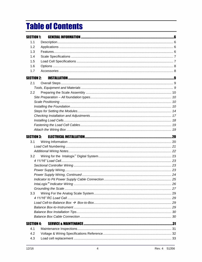
SECTION 1: GENERAL INFORMATION ..........................................................................................................................................6
1.1 Description ............................................................................................................................... 6
1.2 Applications ............................................................................................................................. 6
1.3 Features ................................................................................................................................... 6
1.4 Scale Specifications ................................................................................................................ 7
1.5 Load Cell Specifications .......................................................................................................... 7
1.6 Options .................................................................................................................................... 8
1.7 Accessories ............................................................................................................................. 8
SECTION 2: INSTALLATION .............................................................................................................................................................9
2.1 Overall Steps ........................................................................................................................... 9
Tools, Equipment and Materials ..................................................................................................... 9
2.2 Preparing the Scale Assembly .............................................................................................. 10
Site Preparation – All foundation types ......................................................................................... 10
Scale Positioning .......................................................................................................................... 10
Installing the Foundation ............................................................................................................... 10
Steps for Setting the Modules ....................................................................................................... 14
Checking Installation and Adjustments ......................................................................................... 17
Installing Load Cells ...................................................................................................................... 18
Fastening the Load Cell Cables .................................................................................................... 19
Attach the Wiring Box ................................................................................................................... 19
SECTION 3: ELECTRICAL INSTALLATION ................................................................................................................................. 20
3.1 Wiring Information ................................................................................................................. 20
Load Cell Numbering .................................................................................................................... 21
Additional Wiring Notes ................................................................................................................. 22
3.2 Wiring for the Intalogix Digital System ................................................................................ 23
4 11/16” Load Cell ......................................................................................................................... 23
Sectional Controller Wiring ........................................................................................................... 23
Power Supply Wiring ..................................................................................................................... 23
Power Supply Wiring, Continued .................................................................................................. 24
Indicator to Pit Power Supply Cable Connection .......................................................................... 25
IntaLogix Indicator Wiring ........................................................................................................... 26
Grounding the Scale ..................................................................................................................... 27
3.3 Wiring For the Analog Scale System ..................................................................................... 29
4 11/16” RC Load Cell .................................................................................................................. 29
Load Cell-to-Balance Box Box-to-Box ..................................................................................... 29
Balance Box-to-Instrument ........................................................................................................... 29
Balance Box Installation Tips ........................................................................................................ 30
Balance Box Cable Connection .................................................................................................... 30
SECTION 4: SERVICE & MAINTENANCE ....................................................................................................................................31
4.1 Maintenance Inspections ....................................................................................................... 31
4.2 Voltage & Wiring Specifications Reference ........................................................................... 32
4.3 Load cell replacement ........................................................................................................... 33
Section 1: General Information
12/16 5 Rev. 4 51356
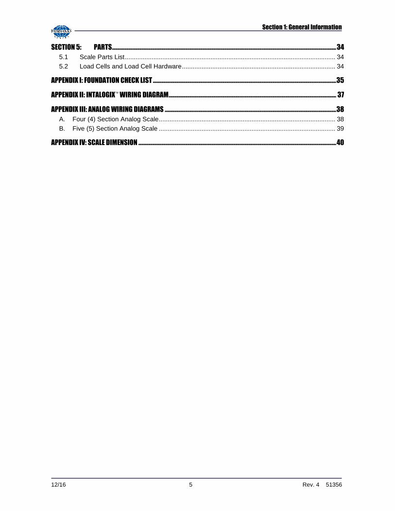
SECTION 5: PARTS .......................................................................................................................................................................... 34
5.1 Scale Parts List ...................................................................................................................... 34
5.2 Load Cells and Load Cell Hardware ...................................................................................... 34
APPENDIX I: FOUNDATION CHECK LIST ........................................................................................................................................... 35
APPENDIX II: INTALOGIX WIRING DIAGRAM ............................................................................................................................... 37
APPENDIX III: ANALOG WIRING DIAGRAMS .................................................................................................................................. 38
A. Four (4) Section Analog Scale................................................................................................... 38
B. Five (5) Section Analog Scale ................................................................................................... 39
APPENDIX IV: SCALE DIMENSION ...................................................................................................................................................... 40
12/16 6 Rev. 4 51356
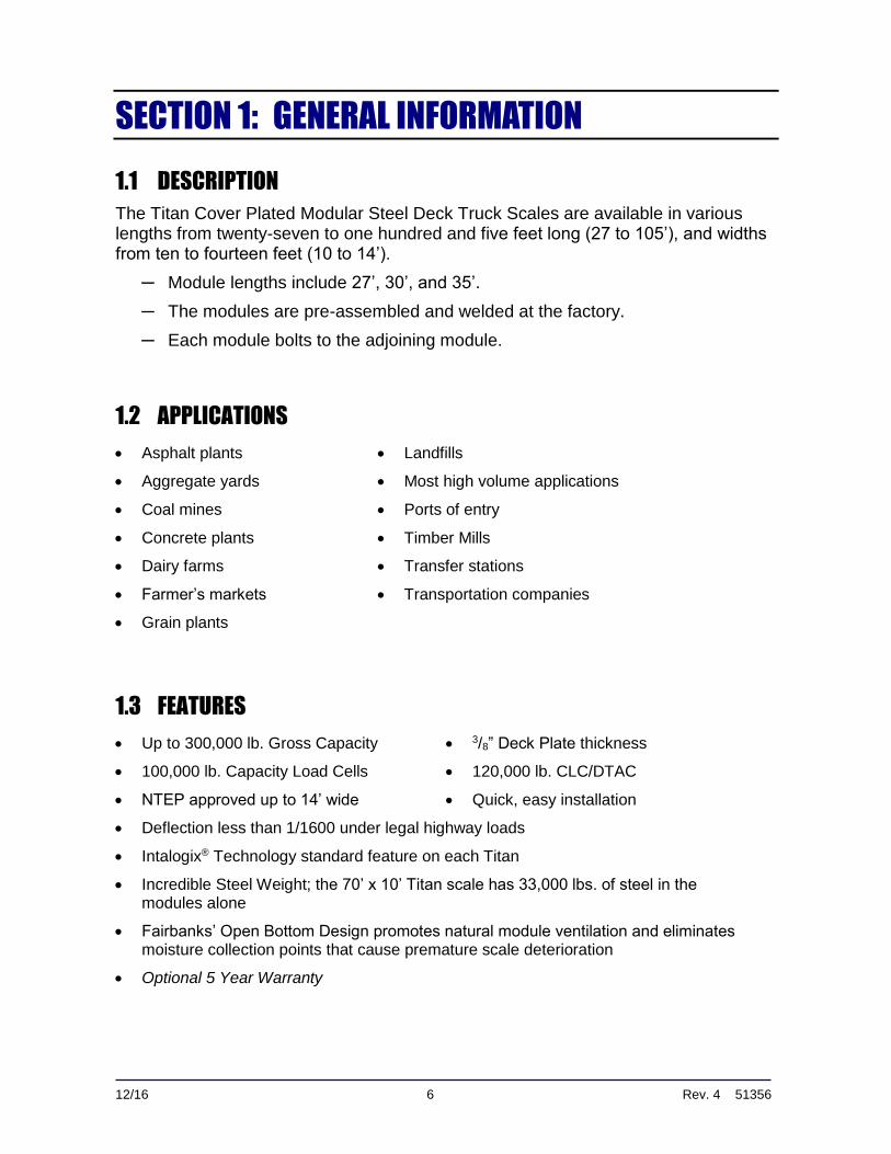
SECTION 1: GENERAL INFORMATION
1.1 DESCRIPTION
The Titan Cover Plated Modular Steel Deck Truck Scales are available in various lengths from twenty-seven to one hundred and five feet long (27 to 105’), and widths from ten to fourteen feet (10 to 14’).
─ Module lengths include 27’, 30’, and 35’.
─ The modules are pre-assembled and welded at the factory.
─ Each module bolts to the adjoining module.
1.2 APPLICATIONS
Asphalt plants Landfills
Aggregate yards Most high volume applications
Coal mines Ports of entry
Concrete plants Timber Mills
Dairy farms Transfer stations
Farmer’s markets Transportation companies
Grain plants
1.3 FEATURES
Up to 300,000 lb. Gross Capacity 3/8” Deck Plate thickness
100,000 lb. Capacity Load Cells 120,000 lb. CLC/DTAC
NTEP approved up to 14’ wide Quick, easy installation
Deflection less than 1/1600 under legal highway loads
Intalogix® Technology standard feature on each Titan
Incredible Steel Weight; the 70’ x 10’ Titan scale has 33,000 lbs. of steel in the modules alone
Fairbanks’ Open Bottom Design promotes natural module ventilation and eliminates moisture collection points that cause premature scale deterioration
Optional 5 Year Warranty
Section 1: General Information
12/16 7 Rev. 4 51356
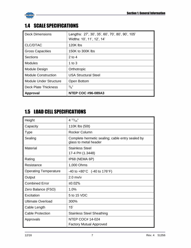
1.4 SCALE SPECIFICATIONS
Deck Dimensions Lengths: 27’, 30’, 35’, 60’, 70’, 80’, 90’, 105’
Widths: 10’, 11’, 12’, 14’
CLC/DTAC 120K lbs
Gross Capacities 150K to 300K lbs
Sections 2 to 4
Modules 1 to 3
Module Design Orthotropic
Module Construction USA Structural Steel
Module Under Structure Open Bottom
Deck Plate Thickness 3/8”
Approval NTEP COC #96-089A3
1.5 LOAD CELL SPECIFICATIONS
Height 4 11/16”
Capacity 110K lbs (50t)
Type Rocker Column
Sealing Complete hermetic sealing; cable entry sealed by glass to metal header
Material Stainless Steel
17-4 PH (1.3448)
Rating IP68 (NEMA 6P)
Resistance 1,000 Ohms
Operating Temperature -40 to +80C (-40 to 176F)
Output 2.0 mv/v
Combined Error ≤0.02%
Zero Balance (FSO) 1.0%
Excitation 5 to 15 VDC
Ultimate Overload 300%
Cable Length 15’
Cable Protection Stainless Steel Sheathing
Approvals NTEP COC# 14-024
Factory Mutual Approved
Section 1: General Information
12/16 8 Rev. 4 51356
1.6 OPTIONS
Deck Runners 300,000 lb. Gross Capacity
Rub Rails Custom Widths/Lengths
Drop Plates
Blow-Down Plates
1.7 ACCESSORIES
Weight Indicators Report & Ticket Printers
Unattended Automated Systems Custom Software
Traffic Signals Remote Displays
12/16 9 Rev. 4 51356
SECTION 2: INSTALLATION
2.1 OVERALL STEPS
1. Foundation check, layout, and base plate setting
2. Preparing tools, materials, documentation and renting a crane.
3. Setting up the modules
4. Setting the modules on load cells.
Tools, Equipment and Materials
Certified Prints
A mobile crane of sufficient lifting capacity to safely lift and place the weighbridge modules.
─ Approximate maximum weight of steel modules is 8 tons.
Four equal length twenty foot (4-20 ft.) lifting chains or cables with hooks.
IMPORTANT NOTE: The installer MUST reserve Crane and Chains/Cables in
advance from a local rental service company.
Machinist’s Levels (Starrett #134 & 132-6).
Hand tools.
Hammer Drill with 5/8” x 36” bit.
Hydraulic jacks.
─ Steel modules: Two ten ton (2-10 ton) hydraulic jacks.
Hand pump (93297).
Six feet (6’) Hose (93298).
100' steel tape measure.
Stringline or chalkline (both)
Pry bars.
Quality grease and anti-seize.
Load Cell Locating Tools, one for each load cell, available for purchase through
Customer Service (157069)

Section 2: Installation
12/16 10 Rev. 4 51356
2.2 PREPARING THE SCALE ASSEMBLY
Site Preparation – All foundation types
1. Assist the customer in selecting a site which allows easy access to and from the scale, ensuring enough area for straight and level approaches, and to meet all State and Local Weights and Measures Regulations.
─ The site needs good drainage away from the scale, elevated enough so the surrounding areas drain away from the scale site.
─ Obtain all the necessary permits and licenses prior to beginning construction.
2. Using a transit, sight in and mark with stakes the area where the placement is to occur, and where supports and forms are to be built.
─ When constructing forms, make sure they are plumb, square, and level.
─ Place and compact gravel into the base of the forms, if necessary.
Scale Positioning
Position the scale so that vehicles can approach and exit it easily.
─ Smooth and level approaches are required at each end of the platform to reduce loading shock, and to facilitate testing of the scale.
─ Approaches must conform to the requirements of the law in the state in which the scale is being installed.
▪ In the absence of such laws, the approaches must conform to paragraph
UR.2.6 of the National Institute of Standards and Technology Handbook 44, which states that the first 10 feet must be level and on the
same plane as the scale platform.
The platform should be visible from the instrument location.
Surface water must drain easily, and not collect, under the scale.
Installing the Foundation
1. Cut and position rebar into the form exactly as the schedule details it in the Fairbanks certified foundation prints.
2. The scale is designed to anchor to the foundation, using expansion anchors which are inserted into the concrete after it has cured.
─ Expansion anchors are recommended because of the flexibility allowed in final positioning of the scale.
3. Pour concrete, using a mix to yield a minimum of 3,500 psi compressive strength.

Section 2: Installation
12/16 11 Rev. 4 51356
Installing the Foundation, Continued
4. Vibrate the concrete into position to ensure consistency.
─ All concrete work MUST conform to standards set forth by the American Concrete Institute Code.
─ Allow concrete to cure several days before erecting the scale.
5. Remove the forms and backfill for proper drainage.
─ A slope away from the scale is recommended.
Allow concrete to cure for twenty-eight (28) days, or until a test
cylinder indicates the concrete has reached its design strength before allowing traffic on the scale.
NOTE: Always… “CALL BEFORE YOU DIG”.
1-888-258-0808
Section 2: Installation
12/16 12 Rev. 4 51356
Installing the Foundation, Continued
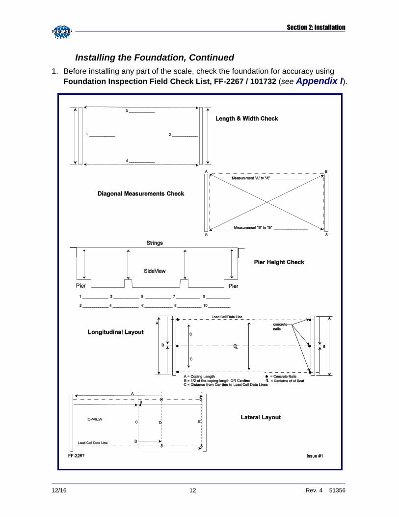
1. Before installing any part of the scale, check the foundation for accuracy using
Foundation Inspection Field Check List, FF-2267 / 101732 (see Appendix I).
Section 2: Installation
12/16 13 Rev. 4 51356
Installing the Foundation, Continued
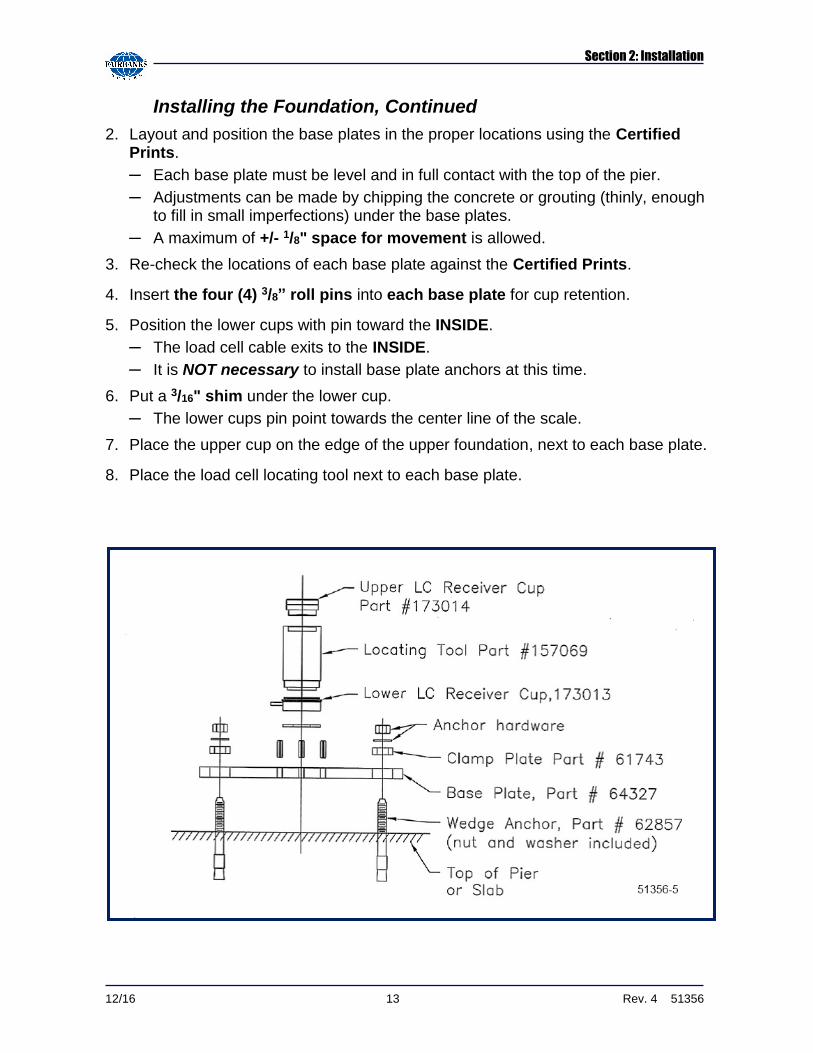
2. Layout and position the base plates in the proper locations using the Certified Prints.
─ Each base plate must be level and in full contact with the top of the pier.
─ Adjustments can be made by chipping the concrete or grouting (thinly, enough to fill in small imperfections) under the base plates.
─ A maximum of +/- 1/8" space for movement is allowed.
3. Re-check the locations of each base plate against the Certified Prints.
4. Insert the four (4) 3/8” roll pins into each base plate for cup retention.
5. Position the lower cups with pin toward the INSIDE.
─ The load cell cable exits to the INSIDE.
─ It is NOT necessary to install base plate anchors at this time.
6. Put a 3/16" shim under the lower cup.
─ The lower cups pin point towards the center line of the scale.
7. Place the upper cup on the edge of the upper foundation, next to each base plate.
8. Place the load cell locating tool next to each base plate.
Section 2: Installation
12/16 14 Rev. 4 51356
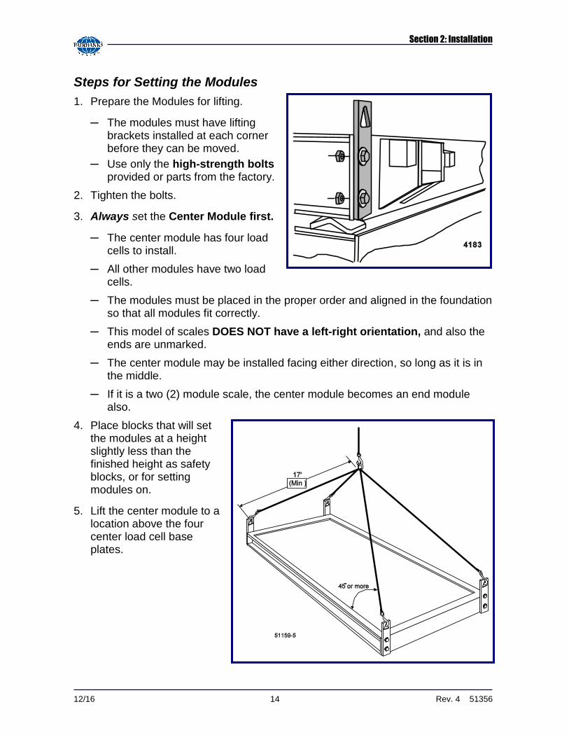
Steps for Setting the Modules
1. Prepare the Modules for lifting.
─ The modules must have lifting brackets installed at each corner before they can be moved.
─ Use only the high-strength bolts provided or parts from the factory.
2. Tighten the bolts.
3. Always set the Center Module first.
─ The center module has four load cells to install.
─ All other modules have two load cells.
─ The modules must be placed in the proper order and aligned in the foundation so that all modules fit correctly.
─ This model of scales DOES NOT have a left-right orientation, and also the ends are unmarked.
─ The center module may be installed facing either direction, so long as it is in the middle.
─ If it is a two (2) module scale, the center module becomes an end module also.
4. Place blocks that will set the modules at a height slightly less than the finished height as safety blocks, or for setting modules on.
5. Lift the center module to a location above the four center load cell base plates.

Section 2: Installation
12/16 15 Rev. 4 51356
OPTION 1: Setting the module directly onto the locating tools
The module sets directly onto the locating tools and the blocks act as safety stands.
6a. Install a Load Cell Bearing Cup into the upper receiver of each corner.
─ Grease helps hold the cup in place.
6b. Insert the upper end of the locating tool over the upper cup on the module.
6c. Lower the module while holding the locating tool upright and guiding the bottom of the tool into the lower cup.
─ When the center module is set on all four locating tools, keep tension on the lifting straps until the module is centered and straight.
6d. Use hydraulic jacks to lift the unit slightly and shift the base plates to get the locating tools PLUMB and the top and bottom flanges FLUSH with the sides of the cup.
While lowering and guiding the module into the
load receiver cups,
KEEP AWAY FROM ALL PINCH POINTS.
D A N G E R
A L W A Y S W E A R E Y E P R O T E C T I O N ! ! !
D A N G E R
Section 2: Installation
12/16 16 Rev. 4 51356
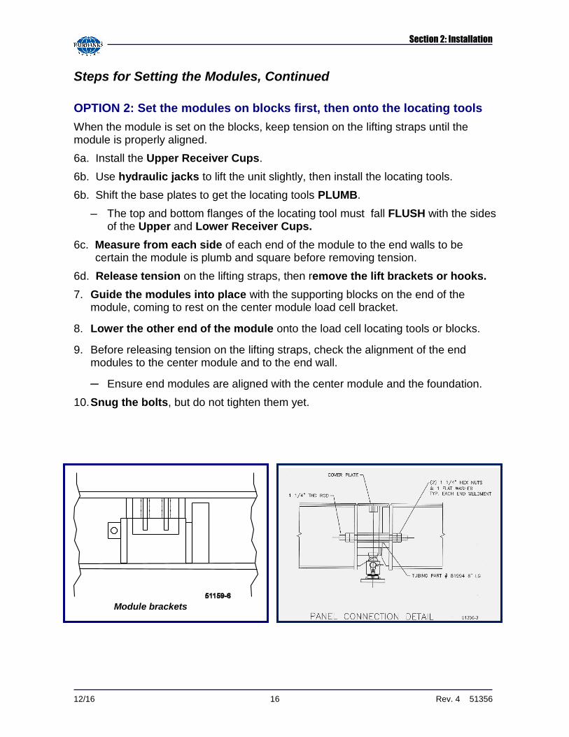
Steps for Setting the Modules, Continued
OPTION 2: Set the modules on blocks first, then onto the locating tools
When the module is set on the blocks, keep tension on the lifting straps until the module is properly aligned.
6a. Install the Upper Receiver Cups.
6b. Use hydraulic jacks to lift the unit slightly, then install the locating tools.
6b. Shift the base plates to get the locating tools PLUMB.
─ The top and bottom flanges of the locating tool must fall FLUSH with the sides of the Upper and Lower Receiver Cups.
6c. Measure from each side of each end of the module to the end walls to be certain the module is plumb and square before removing tension.
6d. Release tension on the lifting straps, then remove the lift brackets or hooks.
7. Guide the modules into place with the supporting blocks on the end of the module, coming to rest on the center module load cell bracket.
8. Lower the other end of the module onto the load cell locating tools or blocks.
9. Before releasing tension on the lifting straps, check the alignment of the end modules to the center module and to the end wall.
─ Ensure end modules are aligned with the center module and the foundation.
10. Snug the bolts, but do not tighten them yet.
Module brackets
Section 2: Installation
12/16 17 Rev. 4 51356
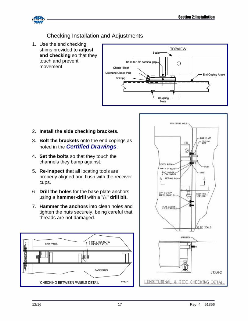
Checking Installation and Adjustments
1. Use the end checking shims provided to adjust end checking so that they touch and prevent movement.
2. Install the side checking brackets.
3. Bolt the brackets onto the end copings as
noted in the Certified Drawings.
4. Set the bolts so that they touch the channels they bump against.
5. Re-inspect that all locating tools are properly aligned and flush with the receiver cups.
6. Drill the holes for the base plate anchors using a hammer-drill with a 5/8" drill bit.
7. Hammer the anchors into clean holes and tighten the nuts securely, being careful that threads are not damaged.
Section 2: Installation
12/16 18 Rev. 4 51356
Installing Load Cells
1. Starting at one end of the assembled platform, place hydraulic jacks at the corners so the section can be lifted off the locating tool.
─ Two (2) hydraulic jacks may be required.
2. Lift the platform so the load cell locating tool can be removed from the upper and lower bearing cups.
3. Once removed, coat both cups with grease provided with the load cell.
4. Carefully lower the scale (using the hydraulic jacks) while seating the bottom of the cell into the lower cup.
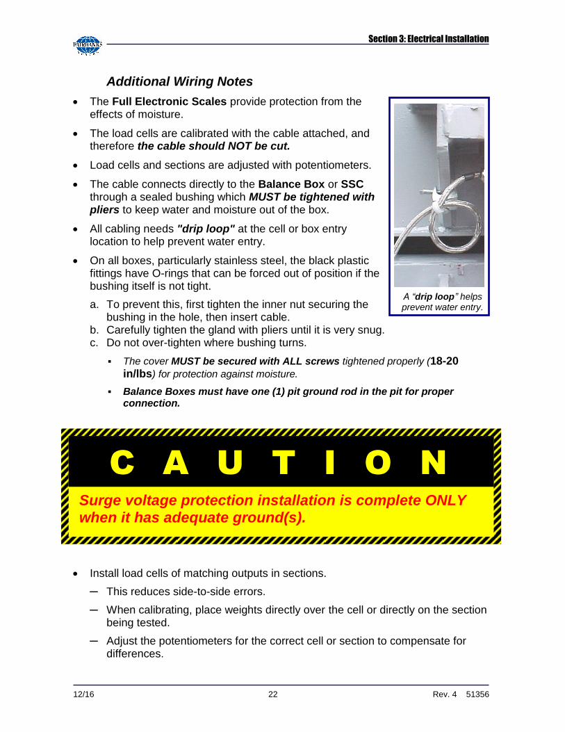
NOTE: Anti rotation must be positioned to inside of scale.
─ Check the scale's level and height, particularly at the approaches.
5. Insert the load cell shims provided to adjust load cell cups for correct height and to ensure that all cells share the proper amount of load.
─ The center section cells have up to twice the deadload of end section cells.
6. Once satisfied with height and level, tighten the bolts.
Section 2: Installation
12/16 19 Rev. 4 51356
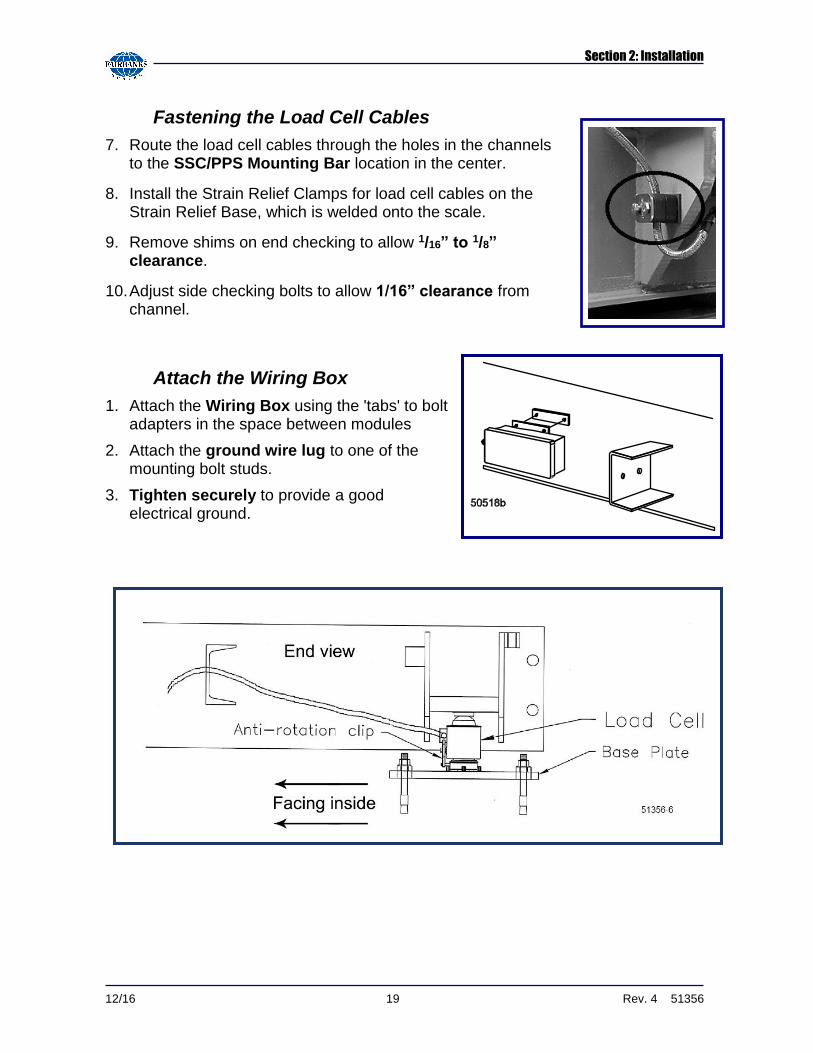
Fastening the Load Cell Cables
7. Route the load cell cables through the holes in the channels to the SSC/PPS Mounting Bar location in the center.
8. Install the Strain Relief Clamps for load cell cables on the Strain Relief Base, which is welded onto the scale.
9. Remove shims on end checking to allow 1/16” to 1/8” clearance.
10. Adjust side checking bolts to allow 1/16” clearance from channel.
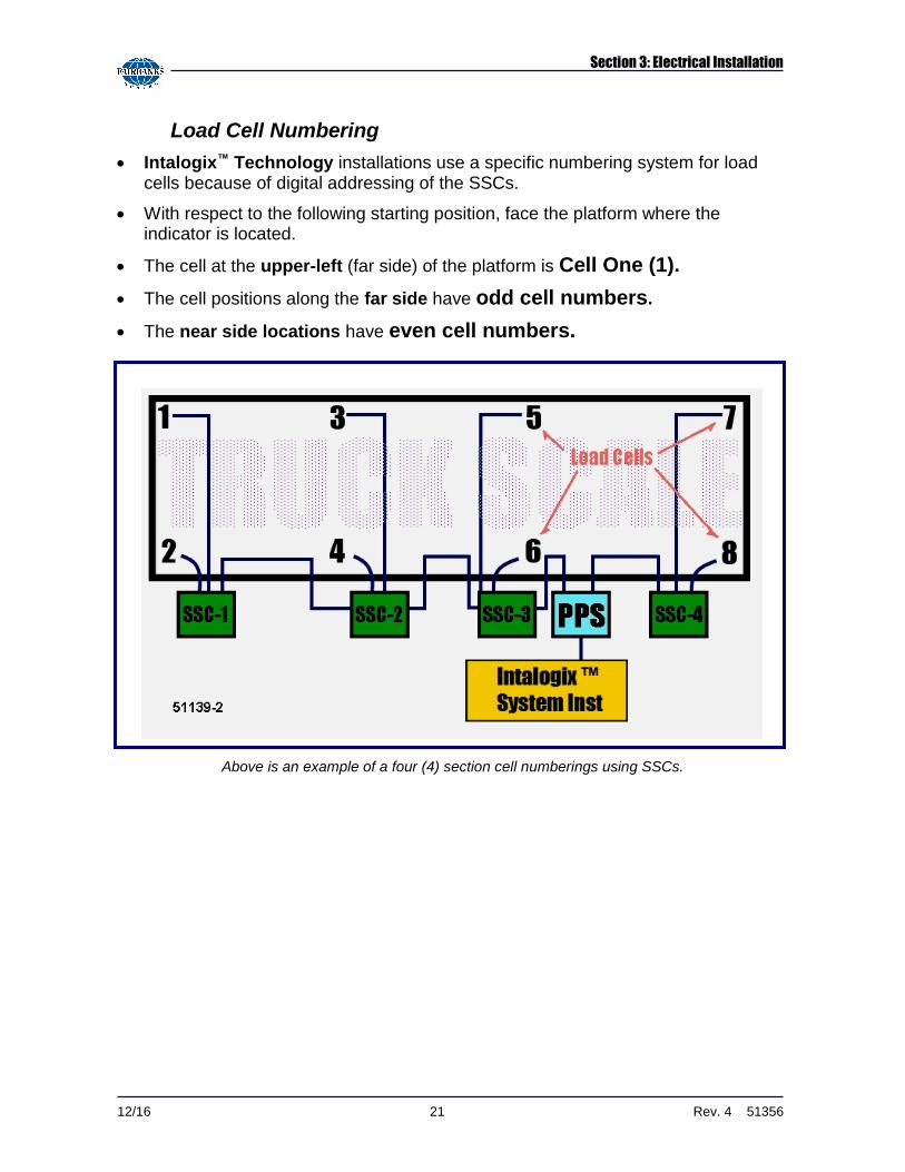
Attach the Wiring Box
1. Attach the Wiring Box using the 'tabs' to bolt adapters in the space between modules
2. Attach the ground wire lug to one of the mounting bolt studs.
3. Tighten securely to provide a good electrical ground.

12/16 20 Rev. 4 51356
SECTION 3: ELECTRICAL INSTALLATION
3.1 WIRING INFORMATION
ALL wiring cable MUST be a minimum of 18 AWG.
─ It must be three (3) pair cable.
─ It must be Cable 17204 (old style), 17246 (new style), or an equivalent.
Maximum Cable Lengths
NUMBER of LOAD CELLS
Maximum Cable Lengths for IDICATOR TO POWER SUPPLY
10 – 700 Ohm Cells 1800 feet
12 – 700 Ohm Cells 1150 feet
14 – 700 Ohm Cells 800 feet
16 – 700 Ohm Cells 575 feet
6 – 350 Ohm Cells 1,575 feet
8 – 350 Ohm Cells 1,000 feet
10 – 350 Ohm Cells 575 feet
** See Appendix I and II for the complete wiring charts of the
indicator, power supply (15236) and the sectional controllers (15235).
A T T E N T I O N
Fairbanks warranty supports ONLY this minimum wiring standard.
Using any lesser quality wiring can void all company contracts.
Section 3: Electrical Installation
12/16 21 Rev. 4 51356
Load Cell Numbering
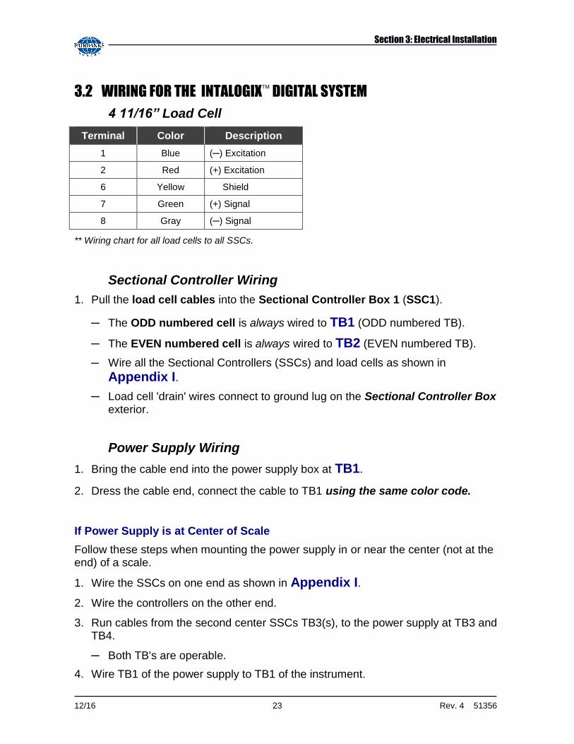
Intalogix™ Technology installations use a specific numbering system for load cells because of digital addressing of the SSCs.
With respect to the following starting position, face the platform where the indicator is located.
The cell at the upper-left (far side) of the platform is Cell One (1).
The cell positions along the far side have odd cell numbers.
The near side locations have even cell numbers.
Above is an example of a four (4) section cell numberings using SSCs.
Section 3: Electrical Installation
12/16 22 Rev. 4 51356
Additional Wiring Notes
The Full Electronic Scales provide protection from the effects of moisture.
The load cells are calibrated with the cable attached, and therefore the cable should NOT be cut.
Load cells and sections are adjusted with potentiometers.
The cable connects directly to the Balance Box or SSC through a sealed bushing which MUST be tightened with pliers to keep water and moisture out of the box.
All cabling needs "drip loop" at the cell or box entry location to help prevent water entry.
On all boxes, particularly stainless steel, the black plastic fittings have O-rings that can be forced out of position if the bushing itself is not tight.
a. To prevent this, first tighten the inner nut securing the bushing in the hole, then insert cable.
b. Carefully tighten the gland with pliers until it is very snug. c. Do not over-tighten where bushing turns.
▪ The cover MUST be secured with ALL screws tightened properly (18-20 in/lbs) for protection against moisture.
▪ Balance Boxes must have one (1) pit ground rod in the pit for proper connection.
Install load cells of matching outputs in sections.
─ This reduces side-to-side errors.
─ When calibrating, place weights directly over the cell or directly on the section being tested.
─ Adjust the potentiometers for the correct cell or section to compensate for differences.
C A U T I O N
Surge voltage protection installation is complete ONLY when it has adequate ground(s).
A “drip loop” helps prevent water entry.
Section 3: Electrical Installation
12/16 23 Rev. 4 51356
3.2 WIRING FOR THE INTALOGIX DIGITAL SYSTEM
4 11/16” Load Cell
Terminal Color Description
1 Blue (─) Excitation
2 Red (+) Excitation
6 Yellow Shield
7 Green (+) Signal
8 Gray (─) Signal
** Wiring chart for all load cells to all SSCs.
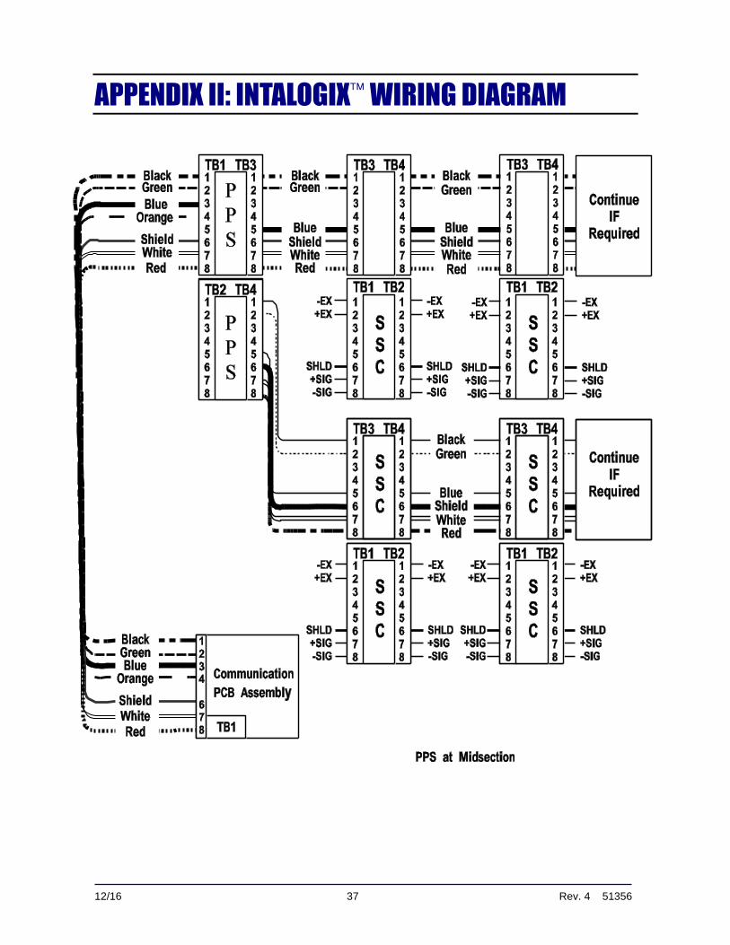
Sectional Controller Wiring
1. Pull the load cell cables into the Sectional Controller Box 1 (SSC1).
─ The ODD numbered cell is always wired to TB1 (ODD numbered TB).
─ The EVEN numbered cell is always wired to TB2 (EVEN numbered TB).
─ Wire all the Sectional Controllers (SSCs) and load cells as shown in
Appendix I.
─ Load cell 'drain' wires connect to ground lug on the Sectional Controller Box exterior.
Power Supply Wiring
1. Bring the cable end into the power supply box at TB1.
2. Dress the cable end, connect the cable to TB1 using the same color code.
If Power Supply is at Center of Scale
Follow these steps when mounting the power supply in or near the center (not at the end) of a scale.
1. Wire the SSCs on one end as shown in Appendix I.
2. Wire the controllers on the other end.
3. Run cables from the second center SSCs TB3(s), to the power supply at TB3 and TB4.
─ Both TB's are operable.
4. Wire TB1 of the power supply to TB1 of the instrument.
Section 3: Electrical Installation
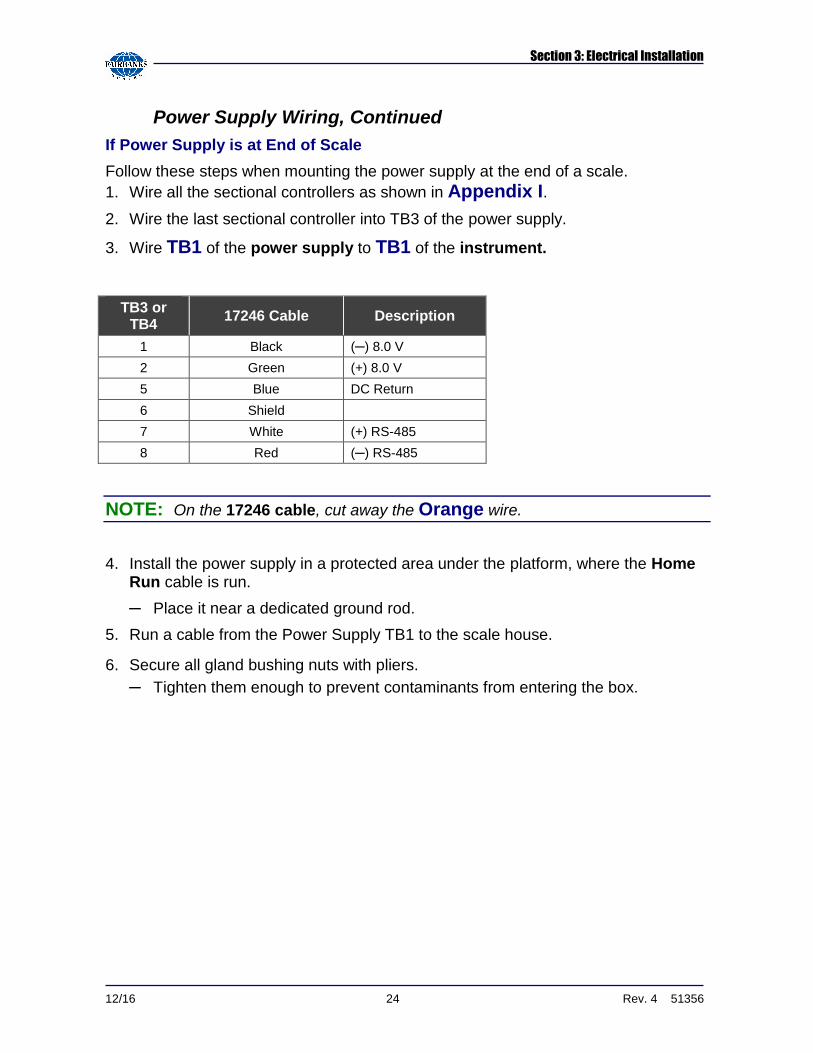
12/16 24 Rev. 4 51356
Power Supply Wiring, Continued
If Power Supply is at End of Scale
Follow these steps when mounting the power supply at the end of a scale.
1. Wire all the sectional controllers as shown in Appendix I.
2. Wire the last sectional controller into TB3 of the power supply.
3. Wire TB1 of the power supply to TB1 of the instrument.
TB3 or TB4
17246 Cable Description
1 Black (─) 8.0 V
2 Green (+) 8.0 V
5 Blue DC Return
6 Shield
7 White (+) RS-485
8 Red (─) RS-485
NOTE: On the 17246 cable, cut away the Orange wire.
4. Install the power supply in a protected area under the platform, where the Home Run cable is run.
─ Place it near a dedicated ground rod.
5. Run a cable from the Power Supply TB1 to the scale house.
6. Secure all gland bushing nuts with pliers.
─ Tighten them enough to prevent contaminants from entering the box.
Section 3: Electrical Installation
12/16 25 Rev. 4 51356
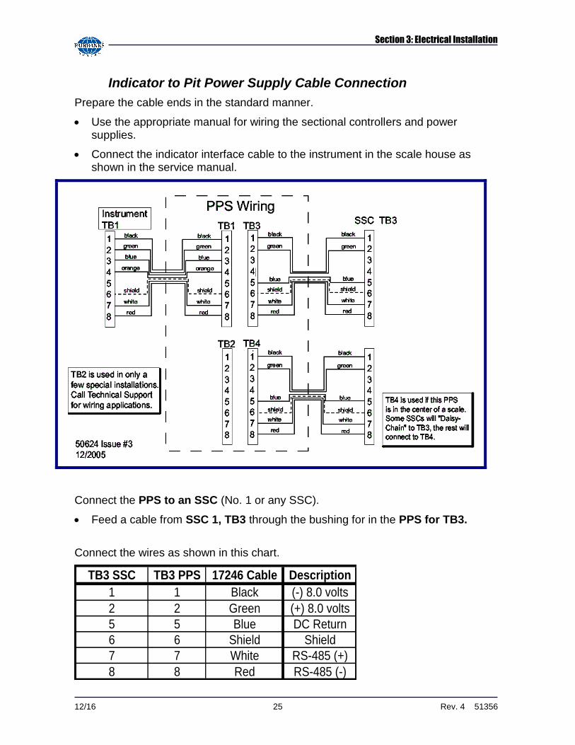
Indicator to Pit Power Supply Cable Connection
Prepare the cable ends in the standard manner.
Use the appropriate manual for wiring the sectional controllers and power supplies.
Connect the indicator interface cable to the instrument in the scale house as shown in the service manual.
Connect the PPS to an SSC (No. 1 or any SSC).
Feed a cable from SSC 1, TB3 through the bushing for in the PPS for TB3.
Connect the wires as shown in this chart.
TB3 SSC TB3 PPS 17246 Cable Description
1 1 Black (-) 8.0 volts
2 2 Green (+) 8.0 volts
5 5 Blue DC Return
6 6 Shield Shield
7 7 White RS-485 (+)
8 8 Red RS-485 (-)
Section 3: Electrical Installation
12/16 26 Rev. 4 51356
Indicator to Pit Power Supply Cable Connection, continued
Wire the PPS to the Instrument.
─ Run the Home-Run Cable from the PPS – TB1 to the Instrument's TB1.
─ Shields are used for DC Return and MUST BE CONNECTED.
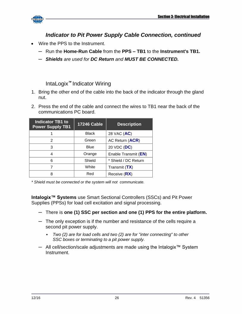
IntaLogix Indicator Wiring
1. Bring the other end of the cable into the back of the indicator through the gland nut.
2. Press the end of the cable and connect the wires to TB1 near the back of the communications PC board.
Indicator TB1 to Power Supply TB1
17246 Cable Description
1 Black 28 VAC (AC)
2 Green AC Return (ACR)
3 Blue 20 VDC (DC)
4 Orange Enable Transmit (EN)
6 Shield * Shield / DC Return
7 White Transmit (TX)
8 Red Receive (RX)
* Shield must be connected or the system will not communicate.
Intalogix™ Systems use Smart Sectional Controllers (SSCs) and Pit Power Supplies (PPSs) for load cell excitation and signal processing.
─ There is one (1) SSC per section and one (1) PPS for the entire platform.
─ The only exception is if the number and resistance of the cells require a second pit power supply.
▪ Two (2) are for load cells and two (2) are for "inter connecting" to other SSC boxes or terminating to a pit power supply.
─ All cell/section/scale adjustments are made using the Intalogix™ System Instrument.
Section 3: Electrical Installation
12/16 27 Rev. 4 51356
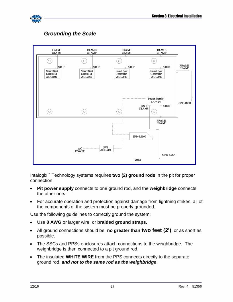
Grounding the Scale
Intalogix™ Technology systems requires two (2) ground rods in the pit for proper connection.
Pit power supply connects to one ground rod, and the weighbridge connects the other one.
For accurate operation and protection against damage from lightning strikes, all of the components of the system must be properly grounded.
Use the following guidelines to correctly ground the system:
Use 8 AWG or larger wire, or braided ground straps.
All ground connections should be no greater than two feet (2’), or as short as
possible.
The SSCs and PPSs enclosures attach connections to the weighbridge. The weighbridge is then connected to a pit ground rod.
The insulated WHITE WIRE from the PPS connects directly to the separate ground rod, and not to the same rod as the weighbridge.
Section 3: Electrical Installation
12/16 28 Rev. 4 51356
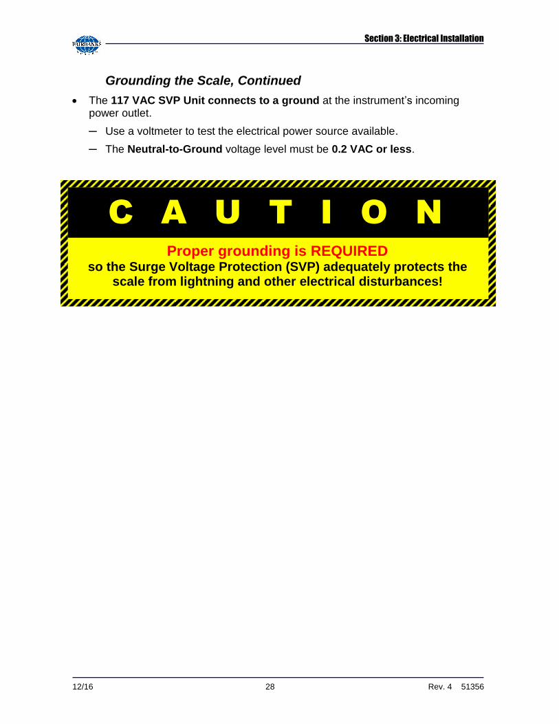
Grounding the Scale, Continued
The 117 VAC SVP Unit connects to a ground at the instrument’s incoming power outlet.
─ Use a voltmeter to test the electrical power source available.
─ The Neutral-to-Ground voltage level must be 0.2 VAC or less.
C A U T I O N
Proper grounding is REQUIRED so the Surge Voltage Protection (SVP) adequately protects the
scale from lightning and other electrical disturbances!
Section 3: Electrical Installation
12/16 29 Rev. 4 51356
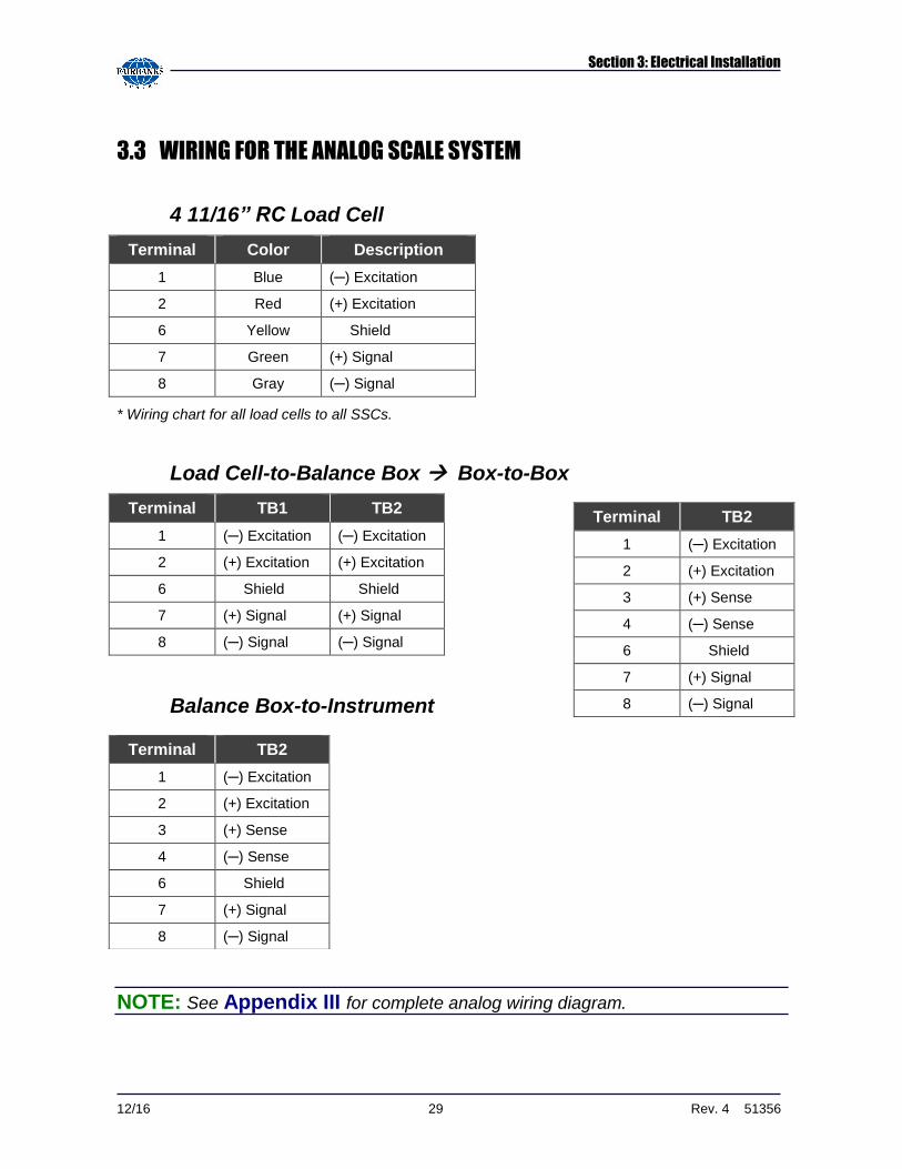
3.3 WIRING FOR THE ANALOG SCALE SYSTEM
4 11/16” RC Load Cell
Terminal Color Description
1 Blue (─) Excitation
2 Red (+) Excitation
6 Yellow Shield
7 Green (+) Signal
8 Gray (─) Signal
* Wiring chart for all load cells to all SSCs.
Load Cell-to-Balance Box Box-to-Box
Terminal TB1 TB2
1 (─) Excitation (─) Excitation
2 (+) Excitation (+) Excitation
6 Shield Shield
7 (+) Signal (+) Signal
8 (─) Signal (─) Signal
Balance Box-to-Instrument
NOTE: See Appendix III for complete analog wiring diagram.
Terminal TB2
1 (─) Excitation
2 (+) Excitation
3 (+) Sense
4 (─) Sense
6 Shield
7 (+) Signal
8 (─) Signal
Terminal TB2
1 (─) Excitation
2 (+) Excitation
3 (+) Sense
4 (─) Sense
6 Shield
7 (+) Signal
8 (─) Signal
Section 3: Electrical Installation
12/16 30 Rev. 4 51356
Balance Box Installation Tips
The balance boxes are interconnected from TB4 to TB3, beginning at the end section where the interface cable conduit enters the scale.
If the conduit enters the scale in the middle, an alternative wiring method is to use 14478 Instrument SVP.
─ This allows separate connections to go in each direction, toward the ends of the scale.
─ Balance Box (21912) is installed at the platform, one box per section.
─ Each Stainless Steel Balance Box has four (4) terminal blocks to connect two (2) load cells and two (2) cables for interconnections to other Balance Boxes and/or to the analog instrument.
Balance Box Cable Connection
1. Fasten the two (2) cables from the two (2) Center Section Boxes into the
Instrument SVP (14478).
─ The cable from the indicator connects to the 14478 Instrument SVP as well.
─ Prepare the cable ends in the standard manner.
─ Connect the indicator interface cable to the instrument in the scale house as instructed by the appropriate indicator service manual.
2. Install load cells of matching outputs in sections.
─ This reduces side-to-side errors.
─ When calibrating, place weights directly over the cell or directly on the section being tested.
─ Adjust the potentiometers for the correct cell or section to compensate for differences.
3. Install the Cover Plates that bridge the gap between modules.
─ They are held in place with 3/4" x 1 1/2" bolts.
─ Use anti-seize or grease on the bolts and bolt holes.
12/16 31 Rev. 4 51356
SECTION 4: SERVICE & MAINTENANCE
4.1 MAINTENANCE INSPECTIONS
Have the customer clean under the platform regularly.
─ Check for accumulations of solid material under the scale which may affect the accuracy, i.e., ice, frozen mud, debris.
─ Check to see that the customer has cleaned under the platform regularly.
─ Inspect and tighten all connecting and cover plate hardware for proper tightness.
The load cell bearing cups should be inspected, cleaned and greased at least TWICE per year.
─ Inspect load cells for damage to the ends/cables, check cups and "O" rings for damage and/or excessive or uneven wear.
─ Inspect and adjust all check bolts using anti-seize on the threads.
─ Ensure that the system is maintaining proper ground connections.
Ensure that the SSCs and the PPSs covers are secure.
─ Check module-to-module bolts for tightness.
─ Examine load cell cables and module interconnect cables for problems.
Section 4: Service & Maintenance
12/16 32 Rev. 4 51356
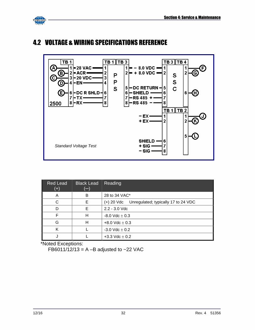
4.2 VOLTAGE & WIRING SPECIFICATIONS REFERENCE
*Noted Exceptions: FB6011/12/13 = A –B adjusted to ~22 VAC
Red Lead (+)
Black Lead (─)
Reading
A B 28 to 34 VAC*
C E (+) 20 Vdc Unregulated; typically 17 to 24 VDC
D E 2.2 - 3.0 Vdc
F H -8.0 Vdc 0.3
G H +8.0 Vdc 0.3
K L -3.0 Vdc 0.2
J L +3.3 Vdc 0.2
Standard Voltage Test
Section 4: Service & Maintenance
12/16 33 Rev. 4 51356
4.3 LOAD CELL REPLACEMENT
1. Remove power from the system at the instrument.
2. Lift the scale using a proper sized and rated hydraulic jack(s) at the corner(s) closest to the "defective" cell location.
3. Disassemble the strain relief device
4. Remove the defective load cell.
5. Check and replace the upper and lower receiving cups and O-Rings if damaged.
6. Apply a small amount of grease on the top and bottom of the new load cell, then insert into the upper receiving cup, positioning the anti-rotation clip.
7. Gently lower the scale assembly, ensuring proper placement of the load cell into the lower cup.
8. Remove the SSC/Junction Box Enclosure Cover.
9. Loosen the gland bushing to free the cable.
10. Unwire the defective load cell from the SSC, noting the wire color code.
11. Wire the new load cell into the SSC/Junction Box.
12. Torque the cover screws to 18-20 in/lbs and tighten all gland nuts with a wrench to secure.
13. Secure the SSC enclosure latches.
14. Re-apply power to the instrument.
15. Test and adjust the scale, and then calibrate it as necessary .
12/16 34 Rev. 4 51356
SECTION 5: PARTS
5.1 SCALE PARTS LIST
Part No. Description
54511 3/4" -10 x 1 ½" Hex Bolt (cover plates)
54236 3/4" Washer (cover plates)
54207 High Strength Bolt 1"-8 x 2 1/2" (for lifting brackets)
157005 Load Cell Base Plate
61743 5/8" x 6" Anchor Bolts
55010 Ground Rod Kit
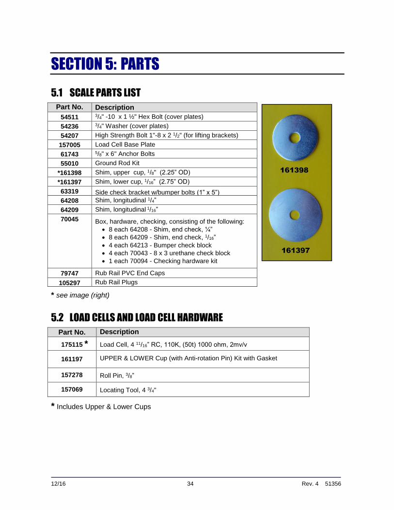
*161398 Shim, upper cup, 1/8" (2.25” OD)
*161397 Shim, lower cup, 1/16” (2.75” OD)
63319 Side check bracket w/bumper bolts (1” x 5”)
64208 Shim, longitudinal 1/4”
64209 Shim, longitudinal 1/16”
70045 Box, hardware, checking, consisting of the following:
8 each 64208 - Shim, end check, ¼”
8 each 64209 - Shim, end check, 1/16”
4 each 64213 - Bumper check block
4 each 70043 - 8 x 3 urethane check block
1 each 70094 - Checking hardware kit
79747 Rub Rail PVC End Caps
105297 Rub Rail Plugs
* see image (right)
5.2 LOAD CELLS AND LOAD CELL HARDWARE
Part No. Description
175115 * Load Cell, 4 11/16” RC, 110K, (50t) 1000 ohm, 2mv/v
161197 UPPER & LOWER Cup (with Anti-rotation Pin) Kit with Gasket
157278 Roll Pin, 3/8”
157069 Locating Tool, 4 3/4"
* Includes Upper & Lower Cups
12/16 35 Rev. 4 51356
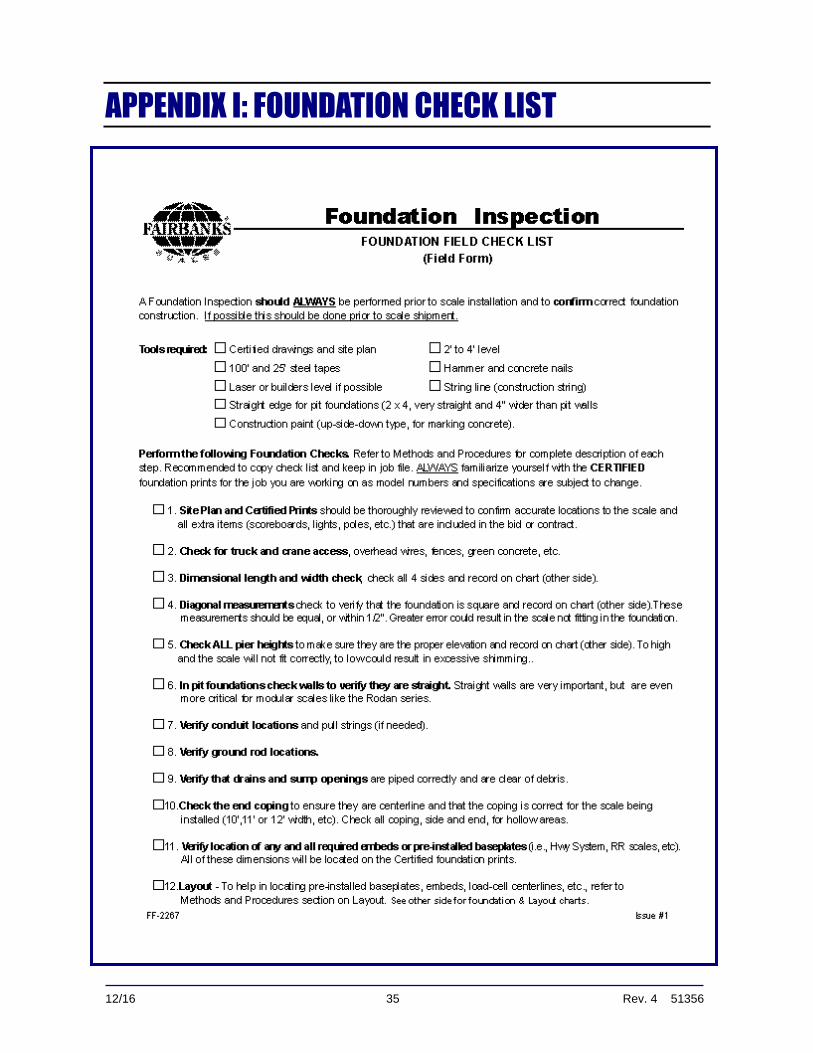
APPENDIX I: FOUNDATION CHECK LIST
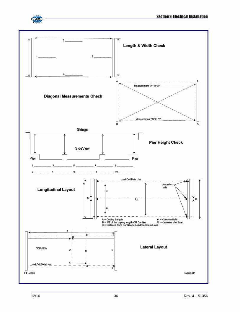
Section 3: Electrical Installation
12/16 36 Rev. 4 51356
12/16 37 Rev. 4 51356
APPENDIX II: INTALOGIX WIRING DIAGRAM
12/16 38 Rev. 4 51356
APPENDIX III: ANALOG WIRING DIAGRAMS
A. FOUR (4) SECTION ANALOG SCALE
Appendix III: Analog Wiring Diagrams
12/16 39 Rev. 4 51356
B. FIVE (5) SECTION ANALOG SCALE
12/16 40 Rev. 4 51356
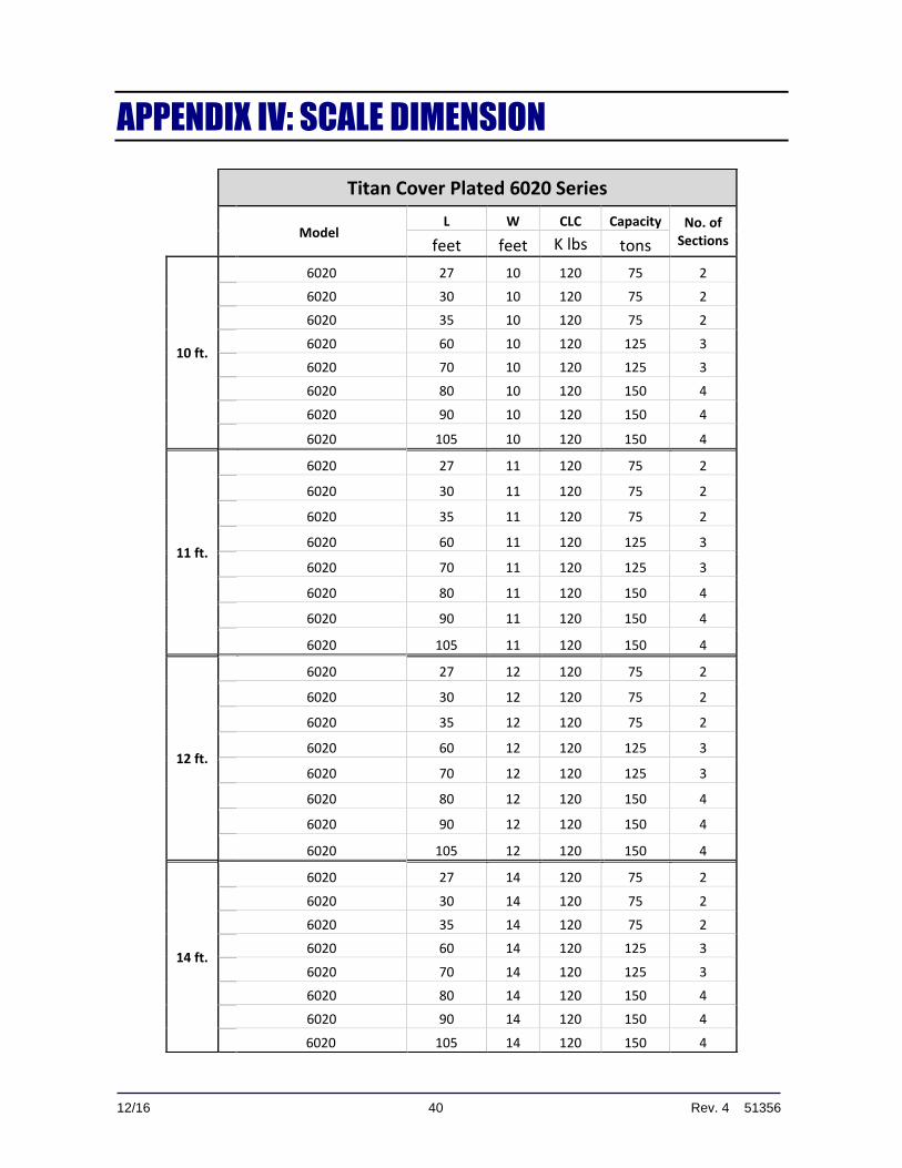
APPENDIX IV: SCALE DIMENSION
Titan Cover Plated 6020 Series
Model L W CLC Capacity No. of
Sections feet feet K lbs tons
10 ft.
6020 27 10 120 75 2
6020 30 10 120 75 2
6020 35 10 120 75 2
6020 60 10 120 125 3
6020 70 10 120 125 3
6020 80 10 120 150 4
6020 90 10 120 150 4
6020 105 10 120 150 4
11 ft.
6020 27 11 120 75 2
6020 30 11 120 75 2
6020 35 11 120 75 2
6020 60 11 120 125 3
6020 70 11 120 125 3
6020 80 11 120 150 4
6020 90 11 120 150 4
6020 105 11 120 150 4
12 ft.
6020 27 12 120 75 2
6020 30 12 120 75 2
6020 35 12 120 75 2
6020 60 12 120 125 3
6020 70 12 120 125 3
6020 80 12 120 150 4
6020 90 12 120 150 4
6020 105 12 120 150 4
14 ft.
6020 27 14 120 75 2
6020 30 14 120 75 2
6020 35 14 120 75 2
6020 60 14 120 125 3
6020 70 14 120 125 3
6020 80 14 120 150 4
6020 90 14 120 150 4
6020 105 14 120 150 4

Titan Series
Cover Plated Scale
6020 Series
Document 51356
Manufactured by Fairbanks Scales, Inc. 821 Locust Street Kansas City, MO 64106
www.fairbanks.com