Embed Size (px)
Citation preview
CRADEN P E R I P H E R A L S C O R P O R A T I O N
DP8 & DP9
DOCUMENT PRINTERS
TECHNICAL MANUAL
P/N 99090 REVISION 10 5/2010
7860 AIRPORT HIGHWAY, PENNSAUKEN, NJ 08109
(856) 488-0700 (856) 488-0925 FAX www.craden.com
WARNING
This equipment generates, uses and can radiate radio frequency energy and, if not installed in accordance with the instruction manual, may cause interference to radio communications. It has been tested with a Class A computing device and has been found to comply with Part 15 of FCC rules, which are designed to provide reasonable protection against such interference when operated in a commercial environment. Operation of this equipment in a residential area is likely to cause interference in which case the user at his own expense will be required to correct the interference.
RECORD OF CHANGES
REVISION DATE ECO‟s PAGES AFFECTED NOTES 1 10/01 ALL Initial Release 2 11/02 ALL Add DP9 3 06/03 1, 6, 7, 12-15 Fast Draft speed 4 01/04 1-3, 6-9, 16, 17, 22, 30, 32 Updated 40, 41, All Tech Dwgs. 5 09/04 1, 4, 7, 8, 26, 30, 34, 37, Add edge sensing, 38, 41 Several Tech Dwgs. Updated 6 02/06 3, 4, 7-10, 20, 25, 27-29, Updated 31-33, 37, 38, 39 Several Tech Dwgs. 7 07/07 ALL Updated 8 02/08 1 Updated 9 09/09 ILLUSTRATIONS Web Release 10 05/10 ALL Updated, hyperlinked
DP8 & DP9 Technical Manual Table of Contents
1.0 DP8 & DP9 DOCUMENT PRINTERS - FUNCTIONAL SPECIFICATIONS 1
2.0 INSTALLATION
2.1 INSTALLATION PROCEDURE 2 2.2 RESHIPMENT 3
3.0 OPERATION
3.1 RIBBON CARTRIDGE LOADING 3 3.2 KEYPAD OPERATION 4 3.3 DISPLAY OPERATION 4 3.4 DOCUMENT INSERTION 5 3.5 CONFIGURATION 5 3.5.1 Printer Parameters 6 3.5.2 Communication Parameters 7 3.5.3 Override Parameters 7 3.5.4 Service Parameters 8 3.6 DIAGNOSTICS 3.6.1 Power Up Diagnostics 8
3.6.2 Enhanced Diagnostics 9 3.7 SELF TEST 9
3.8 LOCAL PRINTING 9 3.9 ERROR CONDITIONS 3.9.1 Document Jam 9 3.9.2 Cover Open 9 3.9.3 Page Overflow 9 3.9.4 Carriage Fault 9 3.9.5 Clear Eject Jam 9 3.9.6 Narrow Document 9 3.10 PROGRAMMING 10 3.10.1 Command Summary 10 3.10.2 Document Movement Commands 11 3.10.3 Print Commands 12 3.10.4 Low Density Graphics Commands 14 3.10.5 High Density Graphics Commands 14 3.10.6 Display Commands 14 3.10.7 Configuration Commands 15 3.10.8 Status and Keypad Commands 15 3.11 Drivers 16 3.11.1 Installing Craden Drivers on WINDOWS 95 OR 98 16 3.11.2 Installing Craden Drivers on WINDOWS NT, 2000, XP, VISTA OR 7 17 3.11.3 Installing Craden USB Drivers 17 3.11.4 Using Printer Resident Device Fonts 17 3.11.5 Writing to the Printer LCD Display 18 3.12 INTERFACING 18 3.12.1 Input Buffer Operation 18 3.12.2 Interface Protocols 18 3.12.3 Interface Signals & Cables 19 3.13 PROBLEM SOLVING 19 3.13.1 No Display or Blocks Displayed 19 3.13.2 Unchangeable Configuration Parameters 19 3.13.3 No Document Motion 20 3.13.4 Carriage Fault or No Carriage Motion 20 3.13.5 No Printing or Light Printing 20
3.13.6 Ribbon Smear 20 3.13.7 Erratic Document Feed, Mispositioning or Overprinting 20 3.13.8 Rollers Run at Power-Up or After Document Ejected 20 3.13.9 Erratic Character Spacing or Carriage Hitting End Stops 20 3.13.10 Interface Inoperative 20
4.0 THEORY OF OPERATION 4.1 OVERVIEW 21 4.1.1 Carriage Drive Assembly 21 4.1.2 Document Drive Assembly 21 4.1.3 Switching Power Supply 21 4.1.4 Main Printed Circuit Board 22 4.1.5 Keypad/Display Assembly 22 4.2 ELECTRONICS IN DETAIL 4.2.1 Low Voltage Supplies 22 4.2.2 Microprocessor System 22 4.2.3 Stepper Motor Drivers 22 4.2.4 Printhead Drivers 25 4.2.5 Keypad and Display 25 4.2.6 Sensors 25 4.2.7 Character Printing 25
5.0 MAINTENANCE 5.1 LUBRICATION AND CLEANING 5.1.1 Lubrication 27 5.1.2 Document Feed Roller Cleaning 27 5.1.3 Sensor Cleaning 27 5.1.4 Printhead Cleaning 28 5.1.5 Document Print Area Cleaning 28 5.1.6 Cabinet Exterior Cleaning 28 5.2 SERVICE PARAMETER SET-UP PROCEDURE 29 5.3 ELECTRICAL ADJUSTMENTS 29 5.4 MECHANICAL ADJUSTMENTS 5.4.1 Printhead Gap 30 5.4.1.1 Ribbon Shield Removal/Replacement 31 5.4.1.1.1 Ribbon Shield Face Inspection 32 5.4.2 Carriage Drive Belt Tension 33 5.4.3 Document Drive Belt Tension 33 5.4.4 Carriage Shaft Cam and Shaft Rack 33 5.4.5 Rear Document Roller Spring Force 33 5.4.6 Auto Alignment Gate Ramp 34 5.4.7 Auto Alignment Gate Height 34 5.4.8 Front Document Roller Spring Force 35 5.4.9 Auto Alignment Skew Sensor Calibration 35 5.5 REPLACEMENT PROCEDURES 5.5.1 Cabinet 35 5.5.2 Main PCB 35 5.5.3 Sensor PCB 36 5.5.4 Keypad 36 5.5.5 Display 36 5.5.6 Power Supply PCB 36 5.5.7 Carriage Motor 36 5.5.8 Document Motor 37 5.5.9 Printhead 37 5.5.10 Carriage Drive Belt 37 5.5.11 Document Drive Belt 37
5.6 TROUBLESHOOTING 5.6.1 Basic Troubleshooting Procedure 38 5.6.2 No Display 38 5.6.3 Defective Keypad 38 5.6.4 Defective Sensor 39 5.6.5 No Document Motion 39 5.6.6 No Carriage Motion 40 5.6.7 No Print or Light Print 40 5.6.8 Print Quality 40 5.6.9 Missing Dots 41 5.6.10 Erratic Document Feed or Mispositioning 41 5.6.11 Erratic Character Spacing or False Document Jams 41 5.6.12 Interface Inoperative 41
5.6.13 Diagnostic Flowchart 42
5.7 RECOMMENDED SPARE PARTS 43 5.8 RECOMMENDED SERVICE TOOLS 43
6.0 MAJOR ASSEMBLY ILLUSTRATIONS & PARTS LISTS Printer Diagram 44 Major Assembly Tree 45 73802 Carriage 46 73804 Box 47 73806 Carriage Drive 49 73809 Lower Drive 50 73810 Document Drive 51 73815 Keypad/Display 52 73816 Electromechanical 53 73819 Printer 54
DP8 & DP9 DOCUMENT PRINTERS - FUNCTIONAL SPECIFICATIONS
1.1 Print Characteristics
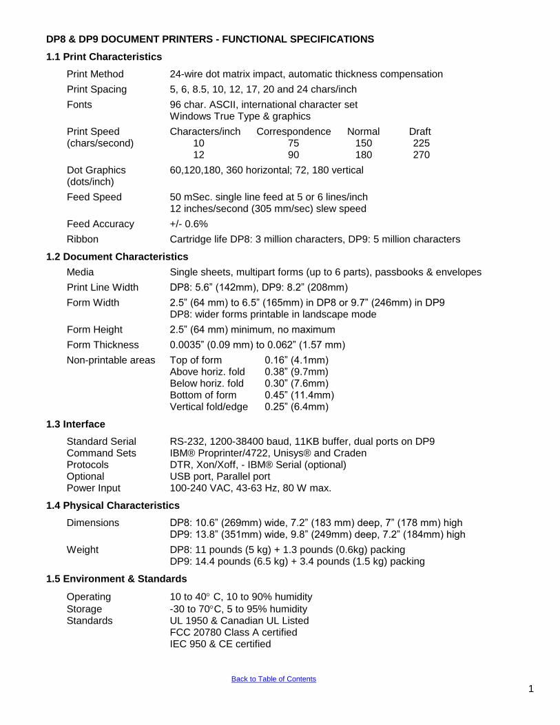
Print Method 24-wire dot matrix impact, automatic thickness compensation
Print Spacing 5, 6, 8.5, 10, 12, 17, 20 and 24 chars/inch
Fonts 96 char. ASCII, international character set Windows True Type & graphics
Print Speed Characters/inch Correspondence Normal Draft (chars/second) 10 75 150 225 12 90 180 270
Dot Graphics 60,120,180, 360 horizontal; 72, 180 vertical (dots/inch)
Feed Speed 50 mSec. single line feed at 5 or 6 lines/inch 12 inches/second (305 mm/sec) slew speed
Feed Accuracy +/- 0.6%
Ribbon Cartridge life DP8: 3 million characters, DP9: 5 million characters
1.2 Document Characteristics
Media Single sheets, multipart forms (up to 6 parts), passbooks & envelopes
Print Line Width DP8: 5.6” (142mm), DP9: 8.2” (208mm)
Form Width 2.5” (64 mm) to 6.5” (165mm) in DP8 or 9.7” (246mm) in DP9 DP8: wider forms printable in landscape mode
Form Height 2.5” (64 mm) minimum, no maximum
Form Thickness 0.0035” (0.09 mm) to 0.062” (1.57 mm)
Non-printable areas Top of form 0.16” (4.1mm) Above horiz. fold 0.38” (9.7mm) Below horiz. fold 0.30” (7.6mm) Bottom of form 0.45” (11.4mm) Vertical fold/edge 0.25” (6.4mm)
1.3 Interface
Standard Serial RS-232, 1200-38400 baud, 11KB buffer, dual ports on DP9 Command Sets IBM® Proprinter/4722, Unisys® and Craden Protocols DTR, Xon/Xoff, - IBM® Serial (optional) Optional USB port, Parallel port Power Input 100-240 VAC, 43-63 Hz, 80 W max.
1.4 Physical Characteristics
Dimensions DP8: 10.6” (269mm) wide, 7.2” (183 mm) deep, 7” (178 mm) high DP9: 13.8” (351mm) wide, 9.8” (249mm) deep, 7.2” (184mm) high
Weight DP8: 11 pounds (5 kg) + 1.3 pounds (0.6kg) packing DP9: 14.4 pounds (6.5 kg) + 3.4 pounds (1.5 kg) packing
1.5 Environment & Standards
Operating 10 to 40 C, 10 to 90% humidity
Storage -30 to 70C, 5 to 95% humidity Standards UL 1950 & Canadian UL Listed FCC 20780 Class A certified IEC 950 & CE certified
1 Back to Table of Contents
2.0 INSTALLATION
2.1 Installation Procedure
1. Read 3.1 to 3.5.2 on Operation and Configuration.
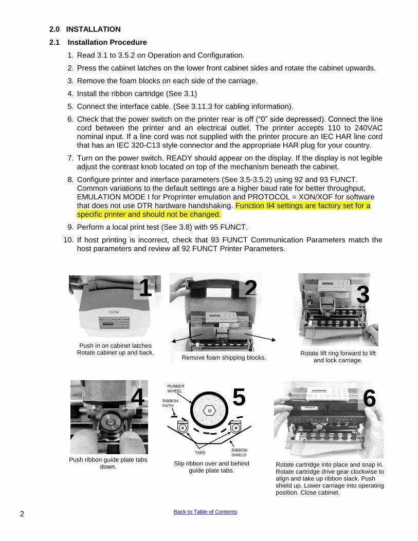
2. Press the cabinet latches on the lower front cabinet sides and rotate the cabinet upwards.
3. Remove the foam blocks on each side of the carriage.
4. Install the ribbon cartridge (See 3.1)
5. Connect the interface cable. (See 3.11.3 for cabling information).
6. Check that the power switch on the printer rear is off (“0” side depressed). Connect the line cord between the printer and an electrical outlet. The printer accepts 110 to 240VAC nominal input. If a line cord was not supplied with the printer procure an IEC HAR line cord that has an IEC 320-C13 style connector and the appropriate HAR plug for your country.
7. Turn on the power switch. READY should appear on the display. If the display is not legible adjust the contrast knob located on top of the mechanism beneath the cabinet.
8. Configure printer and interface parameters (See 3.5-3.5.2) using 92 and 93 FUNCT. Common variations to the default settings are a higher baud rate for better throughput, EMULATION MODE I for Proprinter emulation and PROTOCOL = XON/XOF for software that does not use DTR hardware handshaking. Function 94 settings are factory set for a specific printer and should not be changed.
9. Perform a local print test (See 3.8) with 95 FUNCT.
10. If host printing is incorrect, check that 93 FUNCT Communication Parameters match the host parameters and review all 92 FUNCT Printer Parameters.
Push in on cabinet latches Rotate cabinet up and back.
1
Rotate lift ring forward to lift and lock carriage.
3
Push ribbon guide plate tabs down.
4
Rotate cartridge into place and snap in. Rotate cartridge drive gear clockwise to align and take up ribbon slack. Push shield up. Lower carriage into operating position. Close cabinet.
6
2
Remove foam shipping blocks.
5 RUBBER
WHEEL
RIBBON
SHIELD TABS
RIBBON PATH
Slip ribbon over and behind guide plate tabs.
2 Back to Table of Contents
2.2 Reshipment
If possible, retain the original packing material for reshipment. If the original packing material is not used, insure that printer and the printer carriage will not move during shipment and that the unit has sufficient protective padding.
3.0 Operation
3.1 Ribbon Cartridge Loading (see the video at www.craden.com/ribbonchg.wmv )
Generic ribbons may cause printer malfunctions including ribbon stalling, poor print quality, smearing, and printhead failures. Please use Craden ribbons or carefully qualify generic ribbons. To replace a ribbon cartridge, do the following and refer to the drawings on page 2 and above:
1. Depress the cabinet latches on the lower front cabinet sides and rotate the cabinet upwards.
2. Pull the lift ring on the right side of the printer forward to lift and lock the carriage.
3. Push down the ribbon guide tabs on each side of the printhead to lower the ribbon shield.
4. Remove the old cartridge by pulling down on the top and rotate the top edge forward.
5. Guide the new ribbon behind the rubber wheel and over ribbon guide tabs. Insure the ribbon is not twisted.
6. Mount the new ribbon cartridge bottom edge first and rotate the top edge backwards. Turn the cartridge knob clockwise if necessary to lock the cartridge in place.
7. Turn the cartridge knob clockwise to remove the ribbon slack.
8. Push the ribbon shield all the way up and the lift ring backward to lower the carriage. Push down on the carriage to insure that the carriage is fully seated.
9. Rotate the cabinet forward until the latches on both sides engage.
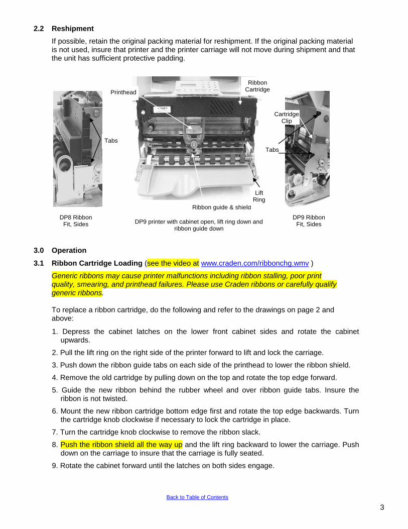
Ribbon guide & shield
DP9 printer with cabinet open, lift ring down and ribbon guide down
Lift Ring
Ribbon Cartridge Printhead
DP9 Ribbon Fit, Sides
Tabs
DP8 Ribbon Fit, Sides
Tabs
Cartridge Clip
3
Back to Table of Contents
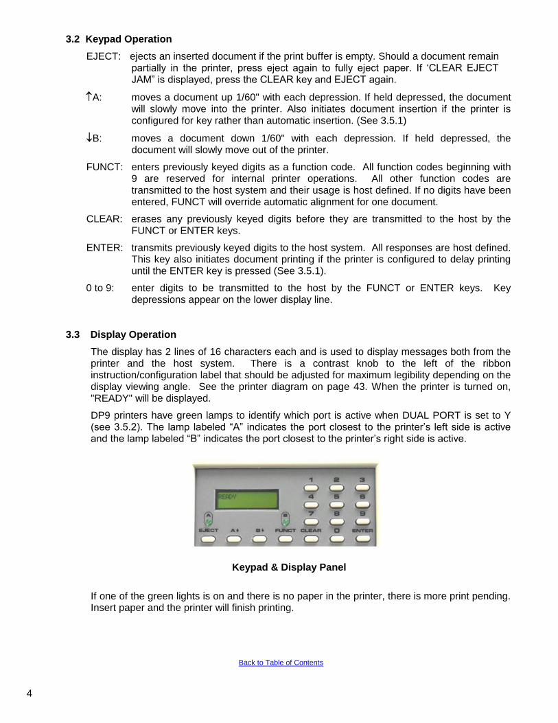
3.2 Keypad Operation
EJECT: ejects an inserted document if the print buffer is empty. Should a document remain partially in the printer, press eject again to fully eject paper. If „CLEAR EJECT JAM” is displayed, press the CLEAR key and EJECT again.
A: moves a document up 1/60" with each depression. If held depressed, the document will slowly move into the printer. Also initiates document insertion if the printer is configured for key rather than automatic insertion. (See 3.5.1)
B: moves a document down 1/60" with each depression. If held depressed, the document will slowly move out of the printer.
FUNCT: enters previously keyed digits as a function code. All function codes beginning with 9 are reserved for internal printer operations. All other function codes are transmitted to the host system and their usage is host defined. If no digits have been entered, FUNCT will override automatic alignment for one document.
CLEAR: erases any previously keyed digits before they are transmitted to the host by the FUNCT or ENTER keys.
ENTER: transmits previously keyed digits to the host system. All responses are host defined. This key also initiates document printing if the printer is configured to delay printing until the ENTER key is pressed (See 3.5.1).
0 to 9: enter digits to be transmitted to the host by the FUNCT or ENTER keys. Key depressions appear on the lower display line.
3.3 Display Operation
The display has 2 lines of 16 characters each and is used to display messages both from the printer and the host system. There is a contrast knob to the left of the ribbon instruction/configuration label that should be adjusted for maximum legibility depending on the display viewing angle. See the printer diagram on page 43. When the printer is turned on, "READY" will be displayed.
DP9 printers have green lamps to identify which port is active when DUAL PORT is set to Y (see 3.5.2). The lamp labeled “A” indicates the port closest to the printer‟s left side is active and the lamp labeled “B” indicates the port closest to the printer‟s right side is active.
Keypad & Display Panel
If one of the green lights is on and there is no paper in the printer, there is more print pending. Insert paper and the printer will finish printing.
4
Back to Table of Contents
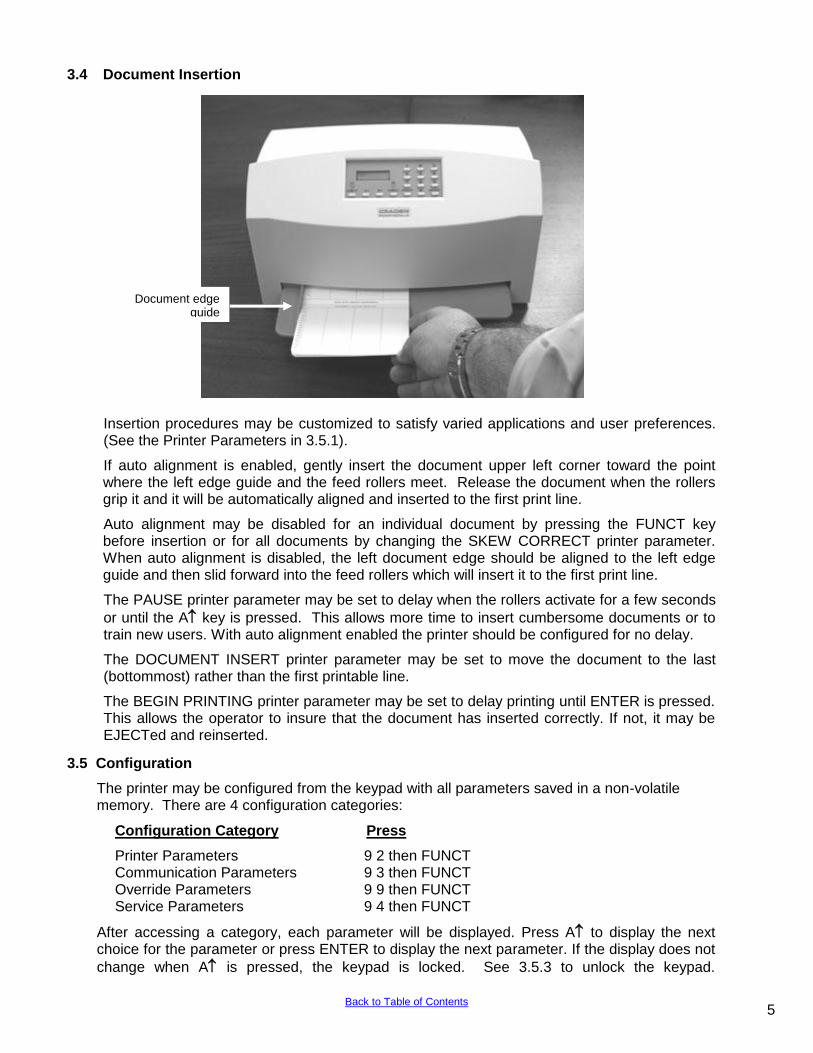
3.4 Document Insertion
Insertion procedures may be customized to satisfy varied applications and user preferences. (See the Printer Parameters in 3.5.1).
If auto alignment is enabled, gently insert the document upper left corner toward the point where the left edge guide and the feed rollers meet. Release the document when the rollers grip it and it will be automatically aligned and inserted to the first print line.
Auto alignment may be disabled for an individual document by pressing the FUNCT key before insertion or for all documents by changing the SKEW CORRECT printer parameter. When auto alignment is disabled, the left document edge should be aligned to the left edge guide and then slid forward into the feed rollers which will insert it to the first print line.
The PAUSE printer parameter may be set to delay when the rollers activate for a few seconds
or until the A key is pressed. This allows more time to insert cumbersome documents or to train new users. With auto alignment enabled the printer should be configured for no delay.
The DOCUMENT INSERT printer parameter may be set to move the document to the last (bottommost) rather than the first printable line.
The BEGIN PRINTING printer parameter may be set to delay printing until ENTER is pressed. This allows the operator to insure that the document has inserted correctly. If not, it may be EJECTed and reinserted.
3.5 Configuration
The printer may be configured from the keypad with all parameters saved in a non-volatile memory. There are 4 configuration categories:
Configuration Category Press
Printer Parameters 9 2 then FUNCT Communication Parameters 9 3 then FUNCT Override Parameters 9 9 then FUNCT Service Parameters 9 4 then FUNCT
After accessing a category, each parameter will be displayed. Press A to display the next choice for the parameter or press ENTER to display the next parameter. If the display does not
change when A is pressed, the keypad is locked. See 3.5.3 to unlock the keypad.
Document edge guide
1 5 Back to Table of Contents
3.5.1 Printer Parameters
Press 9 2 FUNCT to display the following parameters or press 9 0 0 FUNCT to print them on a previously inserted document. Changes may be made as described above. Before proceeding, see 3.4 and select the insertion sequence which best fits your application. Default
settings are indicated in bold print.
DISPLAY REMARKS
LINES/INCH = 5 or 6 Select 5 or 6 lines per inch vertical spacing
CHARS/INCH = 10, 12 or 17
Select 10, 12 or 17 characters per inch horizontal spacing.
PRINT = DRAFT, NORMAL or CQ
Select faster DRAFT, NORMAL, or slower but higher quality CQ print. DRAFT should not be used on passbooks and may degrade DP8 print quality in the rightmost printable column.
QUIET MODE = Y or N Select Y for reduced noise on thin documents. Select N for darker print on thick documents.
DOCUMENT INSERT = TOP or BOTTOM EDGE
Select insertion to the TOP EDGE or BOTTOM EDGE of the document.
DOCUMENT INSERT = WITH X SEC PAUSE or
WITH A KEY
Select automatic insertion 0, 1 or 2 seconds after placing a
document in the input tray or delay insertion until A is pressed to allow more time for aligning documents.
BEGIN PRINTING = IMMEDIATELY or AFTER ENTER KEY
Select to begin printing IMMEDIATELY after the document insertion or delay printing until ENTER is pressed to verify proper alignment.
LINE # 1 = .XXX
Select the distance, between -0.80” and 0.80”, from the document top edge to the center of the first print line. Select
0.25” unless needing software compatibility with another printer.
SKEW DETECTION = CORRECT SKEW, DETECT SKEW, or IGNORE
Select CORRECT SKEW to automatically align skewed documents, DETECT SKEW to detect but not align skewed documents, or IGNORE to disable both skew detection and correction.
SKEW DETECTION
ALLOWED = .030, .050, .080, .110 or .130
Select the maximum skew per 4 inches of document width. Treatment of documents with excess skew is set by the next parameter.
IF FORM SKEWED = ENTER/EJECT KEYS or AUTOMATIC EJECT
If a document has excess skew, ENTER / EJECT KEYS will continue printing if ENTER is pressed or eject the document if EJECT is pressed. AUTOMATIC EJECT will always eject a document with excess skew
NOTE: Many Printer Parameters may be host configured with the HT or other commands.
This allows for dynamic reconfiguration on a document by document or line by line basis.
1 6
Back to Table of Contents
3.5.2 Communication Parameters
Press 9 3 FUNCT to display the following Communication Parameters or press 9 0 0 FUNCT to print them on a previously inserted document. Changes may be made as described in 3.5.
Default settings are indicated in bold.
DISPLAY REMARKS
PROTOCOL = DTR, XON/XOF or PARALLEL INTRF.
Select the protocol to match your system configuration (See 3.11.2). Select PARALLEL if the parallel interface option is installed and skip the next four items.
BAUD RATE = XXXX Select 1200, 2400, 4800, 9600, 19200 or 38400 baud.
WORD LENGTH = 7 or 8 Select 7 or 8 bits/word.
PARITY = XXXX Select EVEN, ODD or NO parity bit.
STOP BITS = 1 or 2 Select 1 or 2 stop bits.
INPUT BUFFER SINGLE LINE or MULTIPLE LINE
Select a SINGLE LINE or a MULTIPLE LINE buffer of 11Kbytes.
EMULATION MODE = C, I , EF4565 or EF4600/EFP95 (EF emulation on DP9 only)
Select C to enable commands used with previous versions of this printer. Other selections enable commands compatible with popular PC based financial printers.
AUTO CARRIAGE RETURN ON FEED = Y or N
Select Y unless compatibility with software written for another printer is needed.
DUAL PORT = Y or N DP9 Only. Select Y unless software cannot accept ports alternating between enabled and disabled. If N is selected, connect to either port but not both.
PAPER OUT = NO DOC or NEVER
Select NO DOC for the parallel interface to indicate paper
empty whenever no document is in the printer or NEVER to never indicate paper empty.
SELECT = DOC PRES or ALWAYS
Select DOC PRES for the parallel interface to indicate off-line
whenever no document is in the printer or ALWAYS to always indicate on-line.
3.5.3 Override Parameters
Press 9 9 FUNCT to display the following Override Parameters. Only trained personnel should make changes.
DISPLAY REMARKS
LOCKED or UNLOCKED LOCKED allows parameters to be displayed but not changed.
UNLOCKED allows parameters to be changed with the A key.
COVER OVERRIDE OFF or ON
OFF requires the cabinet to be closed for printing to occur. ON allows trained personnel to print with the cabinet open. Closing the cabinet automatically sets the override OFF.
7
Back to Table of Contents
3.5.4 Service Parameters
Press 9 4 FUNCT to display the following Service Parameters. These parameters are factory set specifically for each printer and recorded on the configuration label behind the display inside the printer. They do not usually need to be modified by the user. If changes are made to these settings write the new setting on the configuration label.
CAUTION: CHANGE OF THESE PARAMETERS BY UNTRAINED PERSONNEL MAY
RESULT IN INCORRECT PRINTER OPERATION.
DISPLAY REMARKS
TOP OFFSET = XX Adjusts the uppermost print line location. Smaller values print closer to the top edge.
LEFT OFFSET = XX Adjusts the carriage home location during document insertion. Larger values move the carriage to the left.
LEFT MARGIN = XX Adjusts the first column print position if edge sensing is not installed (EDGE SENSOR parameter will not appear below). Larger values move printing to the right.
CAR. ALIGN = XX Aligns lines printed right to left with lines printed left to right. Larger values move right to left printed lines to the left.
FORWARD COMPENSATION = XX
Adjusts distances moved down the document. Larger values increase the distance moved.
REVERSE COMPENSATION = XX
Adjusts distances moved up the document. Larger values increase the distance moved.
EJECT HOLD OFFSET = XX Adjusts how much of the document is held in the feed rollers after it is ejected. Lower values hold less of the document.
CONFIGURATION = XX Selects custom options. Select 00 unless indicated otherwise on the configuration label or incorrect operation may occur.
GATE OFFSET = XX Sets the height of the alignment gate. Larger values raise the gate higher.
NORMAL DARKNESS = -10 to 10
Adjusts darkness at normal print speed. Lower values reduce darkness and increase ribbon life. Select the lowest value that provides suitable legibility on thick forms.
CQ DARKNESS = -10 to 10 Adjusts CQ print darkness.
SET SKEW VALUES SKEWCMP = -15 to 16
Value set by auto alignment skew sensor calibration. Compensates for right document sensor position relative to left document sensor.
SET SKEW VALUES MID-SKEWCMP = -15 to 16
Value set by auto alignment skew sensor calibration. Compensates for middle document sensor position relative to left document sensor.
EDGE SENSOR = XX Adjusts the first column print position from the left paper edge. Larger values move printing to the right.
PRINTHEAD TYPE Only displayed in early version DP8‟s with later firmware installed. Set
to match the printhead body color. Warning: A BLACK head can be damaged if set to SILVER.
3.6 Diagnostics
3.6.1 Power Up Diagnostics
Diagnostics run automatically during power-up. If a fault is detected, ROM or RAM TEST BAD
may be displayed. If a fault occurs, press A to advance to the next test. However, the printer should not be operated.
8 Back to Table of Contents
3.6.2 Enhanced Diagnostics
Diagnostics execute after pressing 9 0 FUNCT. If no faults exist, PROM REVISION XX, ROM
TEST OK and RAM TEST OK will display. If a fault exists, "BAD" will display until A is pressed to advance to the next test. Then SENSORS LFBMRCE will display. L is the left home carriage sensor; F and B are the front and back document sensors, M and R are the middle and right skew sensors, C is the cabinet open sensor and E is the document edge sensor. Any sensor that is covered will have its corresponding indicator extinguished. Each sensor may be activated to check for proper operation. Both operator indicator lights will turn
on (DP9). Press A to conclude this test.
3.7 Self Test
Insert paper and press 9 0 0 FUNCT to print model, firmware ID and configuration settings.
3.8 Local Printing
To print several variable length lines without host commands. Proceed as follows:
1. Insert a form and then press 9 5 FUNCT.
2. In response to CHAR LENGTH = 30, key in a two digit number of characters per line and then press ENTER. Do not print occur across a vertical fold or document edge.
3. In response to LINE COUNT = 01, key in a 2 digit number of lines.
4. Each time ENTER is pressed, that number of lines will be printed.
5. Press EJECT to eject the document and CLEAR to clear the display.
3.9 Error Conditions
3.9.1 Document Jam
In the unlikely event that a document becomes jammed in the printer, printing will stop and "DOCUMENT JAM" will be displayed. The operator must clear the jam condition by moving the printhead left as far as possible and removing the document from the printer.
3.9.2 Cover Open
If the cabinet is opened to replace a ribbon cartridge or clear a document jam, COVER OPEN is displayed and printing is disabled. Printing will resume 3 seconds after the cabinet is closed.
3.9.3 Page Overflow
If the printer is commanded to move past the last printable line on a document it will eject the document and display PAGE OVERFLOW INSERT NEXT PAGE. Printing will resume when another document is inserted.
3.9.4 Carriage Fault
The carriage could not move to the left margin and is probably caused by a jammed carriage or a bad left home sensor.
3.9.5 Clear Eject Jam
At power up or when an eject command is executed and all document sensors do not uncover, “CLEAR EJECT JAM” will be displayed. Assure no document is covering the sensors and the sensors are clean. Turn power off before manually removing a jammed document. If no document is in the printer, this condition may be cleared by pressing the ENTER key while powering the printer on. If the condition will not clear there may be a sensor failure.
3.9.6 Narrow Document
When a document less than 2.4” wide is inserted the middle sensor does not “see” it. NARROW DOCUMENT” is displayed. Press ENTER to proceed or EJECT to abort.
9 Back to Table of Contents
3.10 Programming
CAUTION: DURING PROGRAM DEVELOPMENT ALL PRINTING SHOULD BE DONE ON
SINGLE SHEET PAPER UNTIL PRINT IS CORRECTLY FORMATTED. PRINTING ACROSS
THICK FOLDS AND DOCUMENT EDGES CAN DAMAGE THE PRINTHEAD.
Two separate command sets, C and I, are selectable either from the keypad using 9 3 FUNCT (see 3.5.2) or the interface. Mode C is compatible with previous versions of this printer while mode I is compatible with popular PC based printers. Many commands are identical in both C and I modes. Unique mode C commands are indicated by (C) and unique mode I commands are indicated by (I) in the command summary table. Mode C keypad, display and status and key buffer request commands can still be accessed in Mode I by preceding the Mode C command with a ESC character. A Windows printer driver for an IBM Proprinter X24 may be used but the Craden driver is preferred as it defines common transaction document widths, provides faster throughput in landscape mode, and facilitates writing messages to the display.
3.10.1 Command Summary
ASCII Hex Command
ENQ 05 Status request (use ESC ENQ in mode I)
BEL 07 Load upper display immediate (use ESC BEL in mode I)
BS 08 Reverse line feed (C) or Backspace one character (I)
HT n 09 Configuration download (C) or Horizontal Tab (I)
LF 0A Line feed
VT n 0B Vertical feed (C) or Vertical Tab (I)
FF 0C Eject document
CR 0D Print buffer
SO 0E Begin expanded characters
SI 0F End expanded characters (C) or Begin 17 characters/inch print (I)
DC1/DLE 11/10 Key buffer request (use ESC DC1 or ESC DLEin mode I)
DC2 12 Line count request (C) or Begin 10 characters/inch print (I)
DC3/ETB 13/17 Load upper display delayed (use ESC DC3 or ESC ETB in mode I)
DC4 14 Master reset (C) or End expanded characters (I)
CAN 18 Clear the print buffer (I)
EM 19 Document length request (C)
SUB 1A Status request delayed (use ESC SUB in mode I)
ESC STX 1B 02 Print sideways in landscape mode
ESC SO 1B 0E Begin double height characters (C)
ESC SI 1B 0F End double height characters (C)
ESC - n 1B 2D n Begin (n=1) or end (n=0) underscore (I)
ESC n 1B 3# Feed document up #/120 inches (C)
ESC 0 1B 30 Set 1/8 inch line spacing (I)
ESC 1 1B 31 Set 7/72 inch line spacing (I)
ESC 2 1B 32 Set line spacing stored by prior ESC A (I)
ESC 3 n 1B 33 n Set n/216 inch line spacing (I)
ESC 4 1B 34 Eject the document (I)
ESC 5 n 1B 35 n Begin (n=1) or end (n=0) automatic LF after CR (I)
ESC : 1B 3A Begin 12 character/inch printing (I)
ESC A 1B 41 Begin 60 dot/inch graphics (C) or Store n/72 inch line spacing (I)
ESC B 1B 42 Begin 120 dot/inch graphics (C) or Set vertical tabs (I)
ESC D 1B 44 Set horizontal tabs (I)
ESC E 1B 45 Begin bold print
ESC F 1B 46 End bold print
ESC G 1B 47 Begin correspondence quality (CQ) print
10 Back to Table of Contents
ESC H 1B 48 End correspondence quality print
ESC I n 1B 49 n Begin CQ (n=2) or normal (n=0) print
ESC J n 1B 4A n Feed document up n/216 inches
ESC K 1B 4B Begin 60 dot/inch graphics
ESC L 1B 4C Begin 120 dot/inch graphics
ESC R 1B 52 Set all tabs to default values (I)
ESC S 1 1B 53 01 Begin subscript print
ESC T 1B 54 End subscript print
ESC W n 1B 57 n Begin (n=1) or end (n=0) expanded chars
ESC X mn 1B 58 Set left and right margins at columns m and n
ESC Y 1B 59 Begin 120 dot/inch full speed graphics
ESC Z 1B 5A Begin 240 dot/inch graphics
ESC [ @ 1B 5B 40 Begin or end double high or wide
ESC [ F 1B 5B 46 Set skew allowance
ESC [ I 1B 5B 49 Set character pitch
ESC [ J 1B 5B 4A Set 1/5 inch line spacing
ESC [ d 1B 5B 64 Set print quality
ESC [ g 1B 5B 67 Set graphics mode
ESC ] 1B 5D Reverse line feed
ESC d 1B 64 Move print position
ESC ~ C 1B 7E 43 Select Mode C
ESC ~ I 1B 7E 49 Select Mode I
FS 1C Load lower display immediate (use ESC FS in mode I)
GS 1D Load lower display delayed (use ESC GS in mode I)
RS n 1E n Skip n blank spaces in print line (C)
US 1F Begin/End underscore (C)
3.10.2 Document Movement Commands
Commands common to both C and I modes:
LF moves the document up one line, with line spacing keypad selected (see 3.5.1) or set by an HT (C mode) ESC 0,1,2 or 3 (I mode) command.
ESC J n moves the document up n/216 inches with n being a single binary coded byte.
FF or ESC 4 (I mode only) ejects the document.
ESC [ J followed by the 4 byte hex sequence 02 00 20 01 sets line spacing to 1/5 inch.
ESC ] moves the document down one line, with spacing keypad selected (see 3.5.1) or set by an HT (C mode) or ESC 0,1,2 or 3 (I mode) command.
ESC [ F followed by 00 02 n1 n2 allows skew as follows: n1 n2 = 03 00 no skew control If n1 = 01 then n2 = 00 allows 0.05 in., 01 allows 0.08 in. 02 allows 0.11 in. and 03
allows 0.13 in. of skew
Commands unique to C mode:
VT n moves the document a variable number of lines or steps with n being a single byte, bit coded as 01ULCCCC (C mode only) where:
U = 1 = Up feed U = 0 = Down feed L = 1 = Line feed (1/6” or 1/5”) L = 0 = Step feed (1/60”) CCCC = Line count or step count
ESC n moves the document up (CCCC)/120 inches where n is a single byte bit coded as 0011CCCC (C mode only).
BS moves the document down one line, with spacing keypad selected (see 3.5.1) or set by an HT (C mode) or ESC 0,1,2 or 3 (I mode) command.
11 Back to Table of Contents
Commands unique to I mode:
ESC 0 sets line spacing to 1/8 inch.
ESC 1 sets line spacing to 7/72 inch.
ESC 2 sets line spacing stored by a prior ESC A n.
ESC 3 n sets line spacing to n/216 inch where n is a single binary coded byte.
ESC 5 n sets auto LF if n=1 and resets it if n=0. A line feed is automatically performed when a CR is received if auto LF is set.
ESC A n stores lines spacing of n/72 inch with n being a single binary coded byte but the stored line spacing will not begin until it is set by an ESC 2.
VT moves to the next vertical tab stop or does a LF if no tabs are set.
ESC B nnnnn0 sets up to 64 vertical tabs at each line n with each n being a single binary coded byte and terminating with a 0 byte. ESC B 0 clears all vertical tabs.
ESC R clears all vertical tabs and sets horizontal tabs to default values of column 9 and every eighth column to the right.
If any document movement command (BS, LF, VT, FF, ESC n, ESC 4, ESC J n or ESC ]) has been preceded by any printable ASCII characters, they will be printed before the movement command is executed.
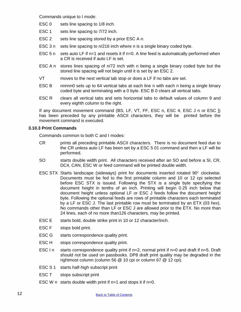
3.10.3 Print Commands
Commands common to both C and I modes:
CR prints all preceding printable ASCII characters. There is no document feed due to the CR unless auto LF has been set by a ESC 5 01 command and then a LF will be performed.
SO starts double width print. All characters received after an SO and before a SI, CR, DC4, CAN, ESC W or feed command will be printed double width.
ESC STX Starts landscape (sideways) print for documents inserted rotated 90 clockwise. Documents must be fed to the first printable column and 10 or 12 cpi selected before ESC STX is issued. Following the STX is a single byte specifying the document height in tenths of an inch. Printing will begin 0.25 inch below that document height unless optional LF or ESC J feeds follow the document height byte. Following the optional feeds are rows of printable characters each terminated by a LF or ESC J. The last printable row must be terminated by an ETX (03 hex). No commands other than LF or ESC J are allowed prior to the ETX. No more than 24 lines, each of no more than126 characters, may be printed.
ESC E starts bold, double strike print in 10 or 12 character/inch.
ESC F stops bold print.
ESC G starts correspondence quality print.
ESC H stops correspondence quality print.
ESC I n starts correspondence quality print if n=2, normal print if n=0 and draft if n=5. Draft should not be used on passbooks. DP8 draft print quality may be degraded in the rightmost column (column 56 @ 10 cpi or column 67 @ 12 cpi).
ESC S 1 starts half-high subscript print
ESC T stops subscript print
ESC W n starts double width print if n=1 and stops it if n=0.
12 Back to Table of Contents
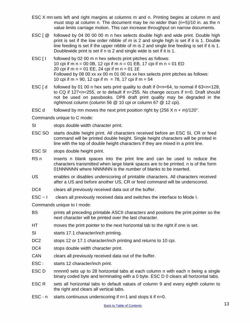
ESC X mn sets left and right margins at columns m and n. Printing begins at column m and must stop at column n. The document may be no wider than (n+5)/10 in. as the n value limits carriage motion. This can increase throughput on narrow documents.
ESC [ @ followed by 04 00 00 00 m n hex selects double high and wide print. Double high print is set if the low order nibble of m is 2 and single high is set if it is 1. Double line feeding is set if the upper nibble of m is 2 and single line feeding is set if it is 1. Doublewide print is set if n is 2 and single wide is set if it is 1.
ESC [ I followed by 02 00 m n hex selects print pitches as follows: 10 cpi if m n = 00 0B, 12 cpi if m n = 01 EB, 17 cpi if m n = 01 ED 20 cpi if m n = 01 EE, 24 cpi if m n = 01 1E
Followed by 08 00 xx xx 00 m 01 00 xx xx hex selects print pitches as follows: 10 cpi if m = 90, 12 cpi if m = 78, 17 cpi if m = 54
ESC [ d followed by 01 00 n hex sets print quality to draft if 0<n<64, to normal if 63<n<128, to CQ if 127<n<255, or to default if n=255. No change occurs if n=0. Draft should not be used on passbooks. DP8 draft print quality may be degraded in the rightmost column (column 56 @ 10 cpi or column 67 @ 12 cpi).
ESC d followed by mn moves the next print position right by (256 X n + m)/120".
Commands unique to C mode:
SI stops double width character print.
ESC SO starts double height print. All characters received before an ESC SI, CR or feed command will be printed double height. Single height characters will be printed in line with the top of double height characters if they are mixed in a print line.
ESC SI stops double height print.
RS n inserts n blank spaces into the print line and can be used to reduce the characters transmitted when large blank spaces are to be printed. n is of the form 01NNNNNN where NNNNNN is the number of blanks to be inserted.
US enables or disables underscoring of printable characters. All characters received after a US and before another US, CR or feed command will be underscored.
DC4 clears all previously received data out of the buffer.
ESC ~ I clears all previously received data and switches the interface to Mode I.
Commands unique to I mode:
BS prints all preceding printable ASCII characters and positions the print pointer so the next character will be printed over the last character.
HT moves the print pointer to the next horizontal tab to the right if one is set.
SI starts 17.1 character/inch printing.
DC2 stops 12 or 17.1 character/inch printing and returns to 10 cpi.
DC4 stops double width character print.
CAN clears all previously received data out of the buffer.
ESC : starts 12 character/inch print.
ESC D nnnnn0 sets up to 28 horizontal tabs at each column n with each n being a single binary coded byte and terminating with a 0 byte. ESC D 0 clears all horizontal tabs.
ESC R sets all horizontal tabs to default values of column 9 and every eighth column to the right and clears all vertical tabs.
ESC - n starts continuous underscoring if n=1 and stops it if n=0.
13 Back to Table of Contents

ESC~C clears all data out of the buffer and switches the interface to Mode C.
3.10.4 Low Density Graphics Commands
These commands emulate low-density graphics printed by a 9-dot printhead. New applications should use the high-density graphics commands intended for a 24-dot printhead.
Low-density graphics may be printed at 60, 120 or 240 dots/inch (dpi) horizontally by 72 dpi vertically. ESC K sets 60 dpi, ESC L or ESC Y set 120 dpi and ESC Z sets 240 dpi. ESC Y prints at full speed but adjacent horizontal dots are prohibited. ESC L prints slower without this restriction. Each command is immediately followed by m and n, a 2 byte data count indicating that the number of following graphic data bytes is m + 256 X n. The maximum data count is 336 for ESC K, 672 for ESC L or ESC Y and 1344 for ESC Z. The high order bit of each graphics data byte is the highest and the low order bit is the lowest of 8 vertical dots printed in a single dot column. Each bit must be set to a 1 for the corresponding dot to be printed.
Low-density graphics may also be printed in C mode only at 60 or 120 dots/inch (dpi) horizontally by 72 or 144 dpi vertically. ESC A must precede each line of 60 dpi data with a maximum of 336 data bytes. ESC B must precede each line of 120 dpi data with a maximum of 672 bytes. Each line of data must be terminated by a feed command, usually a VT e. Each data byte is of the form 1ABCDEF where A is the lowest and F is the highest of 6 vertical dots printed in a single dot column. Each bit must be set to a 1 for the corresponding dot to be printed.
3.10.5 High Density Graphics Commands
High density 24 dot graphics are selected by ESC [ g m n P where m + 256 X n is the following graphics data byte count plus one and P selects graphics densities as follows:
P value: 0 1 2 8 9 10 or 11 12
Density: 60x72 120x72 120x72 60x180 120x180 180x180 360x180
P= 0, 1 and 2 are equivalent to low density ESC K, L and Y commands. P=10 prints at high speed but adjacent horizontal dots are prohibited. P=11 prints slower without this restriction. In the 180 dpi vertical modes, each group of 3 following graphics data bytes will be printed as one 24 dot vertical stroke where the first byte‟s high order bit is the highest and the third byte‟s low order bit is the lowest of the 24 vertical dots printed.
3.10.6 Display Commands
These C mode commands may be used in I mode by preceding them with an ESC.
BEL immediately displays the following 16 characters on the upper line of the alphanumeric display. The characters must not be control characters and there must be exactly 16 displayable characters
FS loads the lower display line just like BEL loads the upper line.
DC3 or ETB operate identically to a BEL command but all previously received print and document movement commands are executed before the upper line of the display is loaded.
GS loads the lower display line just like DC3 loads the upper line.
14
Back to Table of Contents
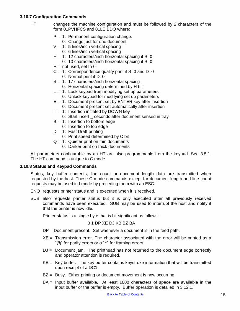
3.10.7 Configuration Commands
HT changes the machine configuration and must be followed by 2 characters of the form 01PVHFCS and 01LEIBDQ where:
P = 1: Permanent configuration change. 0: Change just for one document V = 1: 5 lines/inch vertical spacing 0: 6 lines/inch vertical spacing H = 1: 12 characters/inch horizontal spacing if S=0 0: 10 characters/inch horizontal spacing if S=0 F = not used, set to 0 C = 1: Correspondence quality print if S=0 and D=0 0: Normal print if D=0 S = 1: 17 characters/inch horizontal spacing 0: Horizontal spacing determined by H bit L = 1: Lock keypad from modifying set up parameters 0: Unlock keypad for modifying set up parameters E = 1: Document present set by ENTER key after insertion 0: Document present set automatically after insertion I = 1: Insertion initiated by DOWN key 0: Start insert _ seconds after document sensed in tray B = 1: Insertion to bottom edge 0: Insertion to top edge D = 1: Fast Draft printing 0: Print speed determined by C bit Q = 1: Quieter print on thin documents 0: Darker print on thick documents
All parameters configurable by an HT are also programmable from the keypad. See 3.5.1. The HT command is unique to C mode.
3.10.8 Status and Keypad Commands
Status, key buffer contents, line count or document length data are transmitted when requested by the host. These C mode commands except for document length and line count requests may be used in I mode by preceding them with an ESC.
ENQ requests printer status and is executed when it is received.
SUB also requests printer status but it is only executed after all previously received commands have been executed. SUB may be used to interrupt the host and notify it that the printer is now idle.
Printer status is a single byte that is bit significant as follows:
0 1 DP XE DJ KB BZ BA
DP = Document present. Set whenever a document is in the feed path.
XE = Transmission error. The character associated with the error will be printed as a “@” for parity errors or a “~” for framing errors.
DJ = Document jam. The printhead has not returned to the document edge correctly and operator attention is required.
KB = Key buffer. The key buffer contains keystroke information that will be transmitted upon receipt of a DC1.
BZ = Busy. Either printing or document movement is now occurring.
BA = Input buffer available. At least 1000 characters of space are available in the input buffer or the buffer is empty. Buffer operation is detailed in 3.12.1.
15 Back to Table of Contents
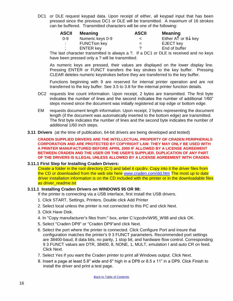
DC1 or DLE request keypad data. Upon receipt of either, all keypad input that has been pressed since the previous DC1 or DLE will be transmitted. A maximum of 16 strokes can be buffered. Transmitted characters will be one of the following:
ASCII Meaning ASCII Meaning 0-9 Numeric keys 0-9 < Either A or B key : FUNCTion key = EJECT key ; ENTER key ? End of buffer
The last character transmitted is always a ?. If a DC1 or DLE is received and no keys have been pressed only a ? will be transmitted.
As numeric keys are pressed, their values are displayed on the lower display line. Pressing ENTER or FUNCT transfers the key strokes to the key buffer. Pressing CLEAR deletes numeric keystrokes before they are transferred to the key buffer.
Functions beginning with 9 are reserved for internal printer operation and are not transferred to the key buffer. See 3.5 to 3.8 for the internal printer function details.
DC2 requests line count information. Upon receipt, 2 bytes are transmitted. The first byte indicates the number of lines and the second indicates the number of additional 1/60” steps moved since the document was initially registered at top edge or bottom edge.
EM requests document length information. Upon receipt, 2 bytes representing the document length (if the document was automatically inserted to the bottom edge) are transmitted. The first byte indicates the number of lines and the second byte indicates the number of additional 1/60 inch steps.
3.11 Drivers (at the time of publication, 64-bit drivers are being developed and tested)
CRADEN SUPPLIED DRIVERS ARE THE INTELLECTUAL PROPERTY OF CRADEN PERIPHERALS
CORPORATION AND ARE PROTECTED BY COPYRIGHT LAW. THEY MAY ONLY BE USED WITH
A PRINTER MANUFACTURED BEFORE APRIL 2000 IF ALLOWED BY A LICENSE AGREEMENT
BETWEEN CRADEN AND THE USER OR THE USER'S SUPPLIER. DUPLICATION OF ANY PART
OF THE DRIVERS IS ILLEGAL UNLESS ALLOWED BY A LICENSE AGREEMENT WITH CRADEN.
3.11.1 First Step for Installing Craden Drivers: Create a folder in the root directory (C:\) and label it cpcdrv. Copy into it the driver files from the CD or downloaded from the web site here www.craden.com/dd.htm The most up to date driver installation information is on the CD included with the printer or in the downloadable files as driver_readme.txt
3.11.1 Installing Craden Drivers on WINDOWS 95 OR 98: If the printer is connecting via a USB interface, first install the USB drivers.
1. Click START, Settings, Printers. Double click Add Printer
2. Select local unless the printer is not connected to this PC and click Next.
3. Click Have Disk.
4. In "Copy manufacturer's files from:" box, enter C:\cpcdrv\W95_W98 and click OK.
5. Select "Craden DP8" or "Craden DP9"and click Next.
6. Select the port where the printer is connected. Click Configure Port and insure that configuration matches the printer's 9 3 FUNCT parameters. Recommended port settings are 38400-baud, 8 data bits, no parity, 1 stop bit, and hardware flow control. Corresponding 9 3 FUNCT values are DTR, 38400, 8, NONE, 1, MULT, emulation I and auto CR on feed. Click Next.
7. Select Yes if you want the Craden printer to print all Windows output. Click Next.
8. Insert a page at least 5.8" wide and 6" high in a DP8 or 8.5 x 11” in a DP9. Click Finish to install the driver and print a test page.
16
Back to Table of Contents
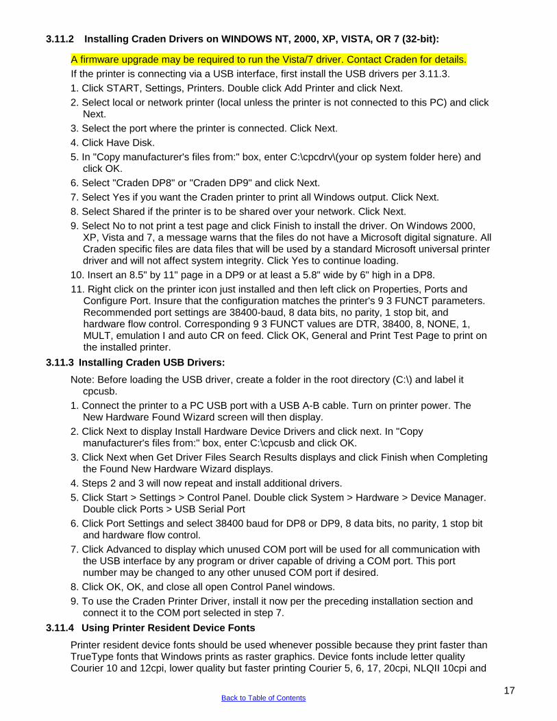
3.11.2 Installing Craden Drivers on WINDOWS NT, 2000, XP, VISTA, OR 7 (32-bit):
A firmware upgrade may be required to run the Vista/7 driver. Contact Craden for details.
If the printer is connecting via a USB interface, first install the USB drivers per 3.11.3.
1. Click START, Settings, Printers. Double click Add Printer and click Next.
2. Select local or network printer (local unless the printer is not connected to this PC) and click Next.
3. Select the port where the printer is connected. Click Next.
4. Click Have Disk.
5. In "Copy manufacturer's files from:" box, enter C:\cpcdrv\(your op system folder here) and click OK.
6. Select "Craden DP8" or "Craden DP9" and click Next.
7. Select Yes if you want the Craden printer to print all Windows output. Click Next.
8. Select Shared if the printer is to be shared over your network. Click Next.
9. Select No to not print a test page and click Finish to install the driver. On Windows 2000, XP, Vista and 7, a message warns that the files do not have a Microsoft digital signature. All Craden specific files are data files that will be used by a standard Microsoft universal printer driver and will not affect system integrity. Click Yes to continue loading.
10. Insert an 8.5" by 11" page in a DP9 or at least a 5.8" wide by 6" high in a DP8.
11. Right click on the printer icon just installed and then left click on Properties, Ports and Configure Port. Insure that the configuration matches the printer's 9 3 FUNCT parameters. Recommended port settings are 38400-baud, 8 data bits, no parity, 1 stop bit, and hardware flow control. Corresponding 9 3 FUNCT values are DTR, 38400, 8, NONE, 1, MULT, emulation I and auto CR on feed. Click OK, General and Print Test Page to print on the installed printer.
3.11.3 Installing Craden USB Drivers:
Note: Before loading the USB driver, create a folder in the root directory (C:\) and label it cpcusb.
1. Connect the printer to a PC USB port with a USB A-B cable. Turn on printer power. The New Hardware Found Wizard screen will then display.
2. Click Next to display Install Hardware Device Drivers and click next. In "Copy manufacturer's files from:" box, enter C:\cpcusb and click OK.
3. Click Next when Get Driver Files Search Results displays and click Finish when Completing the Found New Hardware Wizard displays.
4. Steps 2 and 3 will now repeat and install additional drivers.
5. Click Start > Settings > Control Panel. Double click System > Hardware > Device Manager. Double click Ports > USB Serial Port
6. Click Port Settings and select 38400 baud for DP8 or DP9, 8 data bits, no parity, 1 stop bit and hardware flow control.
7. Click Advanced to display which unused COM port will be used for all communication with the USB interface by any program or driver capable of driving a COM port. This port number may be changed to any other unused COM port if desired.
8. Click OK, OK, and close all open Control Panel windows.
9. To use the Craden Printer Driver, install it now per the preceding installation section and connect it to the COM port selected in step 7.
3.11.4 Using Printer Resident Device Fonts
Printer resident device fonts should be used whenever possible because they print faster than TrueType fonts that Windows prints as raster graphics. Device fonts include letter quality Courier 10 and 12cpi, lower quality but faster printing Courier 5, 6, 17, 20cpi, NLQII 10cpi and
17 Back to Table of Contents
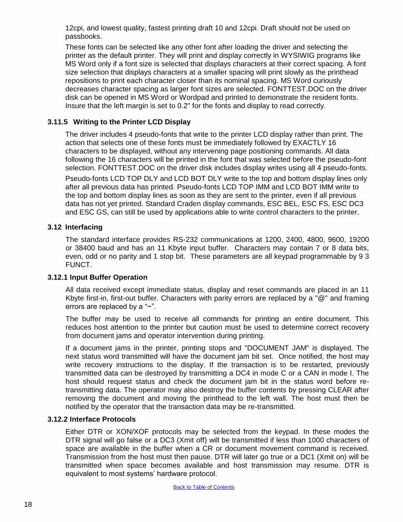
12cpi, and lowest quality, fastest printing draft 10 and 12cpi. Draft should not be used on passbooks.
These fonts can be selected like any other font after loading the driver and selecting the printer as the default printer. They will print and display correctly in WYSIWIG programs like MS Word only if a font size is selected that displays characters at their correct spacing. A font size selection that displays characters at a smaller spacing will print slowly as the printhead repositions to print each character closer than its nominal spacing. MS Word curiously decreases character spacing as larger font sizes are selected. FONTTEST.DOC on the driver disk can be opened in MS Word or Wordpad and printed to demonstrate the resident fonts. Insure that the left margin is set to 0.2" for the fonts and display to read correctly.
3.11.5 Writing to the Printer LCD Display
The driver includes 4 pseudo-fonts that write to the printer LCD display rather than print. The action that selects one of these fonts must be immediately followed by EXACTLY 16 characters to be displayed, without any intervening page positioning commands. All data following the 16 characters will be printed in the font that was selected before the pseudo-font selection. FONTTEST.DOC on the driver disk includes display writes using all 4 pseudo-fonts.
Pseudo-fonts LCD TOP DLY and LCD BOT DLY write to the top and bottom display lines only after all previous data has printed. Pseudo-fonts LCD TOP IMM and LCD BOT IMM write to the top and bottom display lines as soon as they are sent to the printer, even if all previous data has not yet printed. Standard Craden display commands, ESC BEL, ESC FS, ESC DC3 and ESC GS, can still be used by applications able to write control characters to the printer.
3.12 Interfacing
The standard interface provides RS-232 communications at 1200, 2400, 4800, 9600, 19200 or 38400 baud and has an 11 Kbyte input buffer. Characters may contain 7 or 8 data bits, even, odd or no parity and 1 stop bit. These parameters are all keypad programmable by 9 3 FUNCT.
3.12.1 Input Buffer Operation
All data received except immediate status, display and reset commands are placed in an 11 Kbyte first-in, first-out buffer. Characters with parity errors are replaced by a "@" and framing errors are replaced by a “~”.
The buffer may be used to receive all commands for printing an entire document. This reduces host attention to the printer but caution must be used to determine correct recovery from document jams and operator intervention during printing.
If a document jams in the printer, printing stops and "DOCUMENT JAM" is displayed. The next status word transmitted will have the document jam bit set. Once notified, the host may write recovery instructions to the display. If the transaction is to be restarted, previously transmitted data can be destroyed by transmitting a DC4 in mode C or a CAN in mode I. The host should request status and check the document jam bit in the status word before re-transmitting data. The operator may also destroy the buffer contents by pressing CLEAR after removing the document and moving the printhead to the left wall. The host must then be notified by the operator that the transaction data may be re-transmitted.
3.12.2 Interface Protocols
Either DTR or XON/XOF protocols may be selected from the keypad. In these modes the DTR signal will go false or a DC3 (Xmit off) will be transmitted if less than 1000 characters of space are available in the buffer when a CR or document movement command is received. Transmission from the host must then pause. DTR will later go true or a DC1 (Xmit on) will be transmitted when space becomes available and host transmission may resume. DTR is equivalent to most systems‟ hardware protocol.
18
Back to Table of Contents
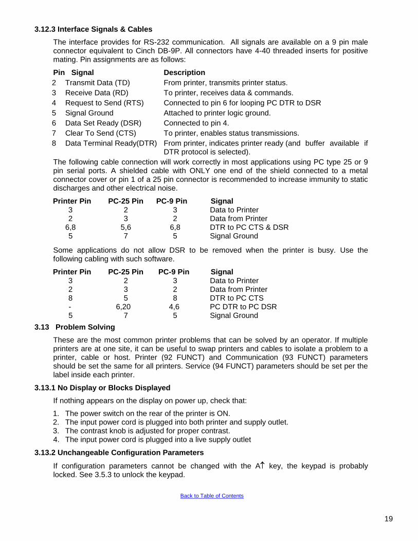
3.12.3 Interface Signals & Cables
The interface provides for RS-232 communication. All signals are available on a 9 pin male connector equivalent to Cinch DB-9P. All connectors have 4-40 threaded inserts for positive mating. Pin assignments are as follows:
Pin Signal Description
2 Transmit Data (TD) From printer, transmits printer status.
3 Receive Data (RD) To printer, receives data & commands.
4 Request to Send (RTS) Connected to pin 6 for looping PC DTR to DSR
5 Signal Ground Attached to printer logic ground.
6 Data Set Ready (DSR) Connected to pin 4.
7 Clear To Send (CTS) To printer, enables status transmissions.
8 Data Terminal Ready(DTR) From printer, indicates printer ready (and buffer available if DTR protocol is selected).
The following cable connection will work correctly in most applications using PC type 25 or 9 pin serial ports. A shielded cable with ONLY one end of the shield connected to a metal connector cover or pin 1 of a 25 pin connector is recommended to increase immunity to static discharges and other electrical noise.
Printer Pin PC-25 Pin PC-9 Pin Signal 3 2 3 Data to Printer 2 3 2 Data from Printer
6,8 5,6 6,8 DTR to PC CTS & DSR 5 7 5 Signal Ground
Some applications do not allow DSR to be removed when the printer is busy. Use the following cabling with such software.
Printer Pin PC-25 Pin PC-9 Pin Signal 3 2 3 Data to Printer 2 3 2 Data from Printer 8 5 8 DTR to PC CTS
- 6,20 4,6 PC DTR to PC DSR 5 7 5 Signal Ground
3.13 Problem Solving
These are the most common printer problems that can be solved by an operator. If multiple printers are at one site, it can be useful to swap printers and cables to isolate a problem to a printer, cable or host. Printer (92 FUNCT) and Communication (93 FUNCT) parameters should be set the same for all printers. Service (94 FUNCT) parameters should be set per the label inside each printer.
3.13.1 No Display or Blocks Displayed
If nothing appears on the display on power up, check that:
1. The power switch on the rear of the printer is ON. 2. The input power cord is plugged into both printer and supply outlet. 3. The contrast knob is adjusted for proper contrast. 4. The input power cord is plugged into a live supply outlet
3.13.2 Unchangeable Configuration Parameters
If configuration parameters cannot be changed with the A key, the keypad is probably locked. See 3.5.3 to unlock the keypad.
19
Back to Table of Contents
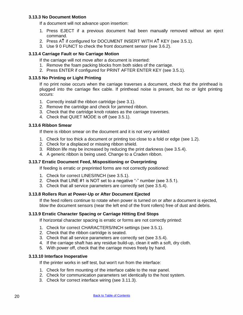
3.13.3 No Document Motion
If a document will not advance upon insertion:
1. Press EJECT if a previous document had been manually removed without an eject command.
2. Press A if configured for DOCUMENT INSERT WITH A KEY (see 3.5.1). 3. Use 9 0 FUNCT to check the front document sensor (see 3.6.2).
3.13.4 Carriage Fault or No Carriage Motion
If the carriage will not move after a document is inserted: 1. Remove the foam packing blocks from both sides of the carriage. 2. Press ENTER if configured for PRINT AFTER ENTER KEY (see 3.5.1).
3.13.5 No Printing or Light Printing
If no print noise occurs when the carriage traverses a document, check that the printhead is plugged into the carriage flex cable. If printhead noise is present, but no or light printing occurs:
1. Correctly install the ribbon cartridge (see 3.1). 2. Remove the cartridge and check for jammed ribbon. 3. Check that the cartridge knob rotates as the carriage traverses. 4. Check that QUIET MODE is off (see 3.5.1).
3.13.6 Ribbon Smear
If there is ribbon smear on the document and it is not very wrinkled:
1. Check for too thick a document or printing too close to a fold or edge (see 1.2). 2. Check for a displaced or missing ribbon shield. 3. Ribbon life may be increased by reducing the print darkness (see 3.5.4). 4. A generic ribbon is being used. Change to a Craden ribbon.
3.13.7 Erratic Document Feed, Mispositioning or Overprinting
If feeding is erratic or preprinted forms are not correctly positioned:
1. Check for correct LINES/INCH (see 3.5.1). 2. Check that LINE #1 is NOT set to a negative “-” number (see 3.5.1). 3. Check that all service parameters are correctly set (see 3.5.4).
3.13.8 Rollers Run at Power-Up or After Document Ejected
If the feed rollers continue to rotate when power is turned on or after a document is ejected, blow the document sensors (near the left end of the front rollers) free of dust and debris.
3.13.9 Erratic Character Spacing or Carriage Hitting End Stops
If horizontal character spacing is erratic or forms are not correctly printed:
1. Check for correct CHARACTERS/INCH settings (see 3.5.1). 2. Check that the ribbon cartridge is seated. 3. Check that all service parameters are correctly set (see 3.5.4). 4. If the carriage shaft has any residue build-up, clean it with a soft, dry cloth. 5. With power off, check that the carriage moves freely by hand.
3.13.10 Interface Inoperative
If the printer works in self test, but won't run from the interface:
1. Check for firm mounting of the interface cable to the rear panel. 2. Check for communication parameters set identically to the host system. 3. Check for correct interface wiring (see 3.11.3).
20 Back to Table of Contents
4.0 THEORY OF OPERATION
4.1 OVERVIEW
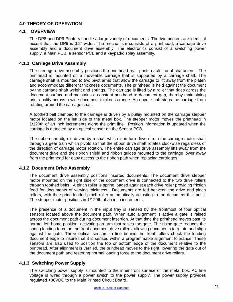
The DP8 and DP9 Printers handle a large variety of documents. The two printers are identical except that the DP9 is 3.2” wider. The mechanism consists of a printhead, a carriage drive assembly and a document drive assembly. The electronics consist of a switching power supply, a Main PCB, a sensor PCB and a keypad/display assembly.
4.1.1 Carriage Drive Assembly
The carriage drive assembly positions the printhead as it prints each line of characters. The printhead is mounted on a moveable carriage that is supported by a carriage shaft. The carriage shaft is mounted to two pivot arms that allow the carriage to lift away from the platen and accommodate different thickness documents. The printhead is held against the document by the carriage shaft weight and springs. The carriage is lifted by a roller that rides across the document surface and maintains a constant printhead to document gap, thereby maintaining print quality across a wide document thickness range. An upper shaft stops the carriage from rotating around the carriage shaft. A toothed belt clamped to the carriage is driven by a pulley mounted on the carriage stepper motor located on the left side of the metal box. The stepper motor moves the printhead in 1/120th of an inch increments along the print line. Position information is updated when the carriage is detected by an optical sensor on the Sensor PCB. The ribbon cartridge is driven by a shaft which is in turn driven from the carriage motor shaft through a gear train which pivots so that the ribbon drive shaft rotates clockwise regardless of the direction of carriage motor rotation. The entire carriage drive assembly lifts away from the document drive and the ribbon shield and ribbon guides mounted to the carriage lower away from the printhead for easy access to the ribbon path when replacing cartridges.
4.1.2 Document Drive Assembly
The document drive assembly positions inserted documents. The document drive stepper motor mounted on the right side of the document drive is connected to the two drive rollers through toothed belts. A pinch roller is spring loaded against each drive roller providing friction feed for documents of varying thickness. Documents are fed between the drive and pinch rollers, with the spring-loaded pinch roller automatically adjusting to the document thickness. The stepper motor positions in 1/120th of an inch increments. The presence of a document in the input tray is sensed by the frontmost of four optical sensors located above the document path. When auto alignment is active a gate is raised across the document path during document insertion. At that time the printhead moves past its normal left home position, activating an arm that raises the gate. The rising gate reduces the spring loading force on the front document drive rollers, allowing documents to rotate and align against the gate. Three optical sensors in line behind the front rollers check the leading document edge to insure that it is sensed within a programmable alignment tolerance. These sensors are also used to position the top or bottom edge of the document relative to the printhead. After alignment is verified, the printhead moves to the right, lowering the gate out of the document path and restoring normal loading force to the document drive rollers.
4.1.3 Switching Power Supply
The switching power supply is mounted to the inner front surface of the metal box. AC line voltage is wired through a power switch to the power supply. The power supply provides regulated +38VDC to the Main Printed Circuit Board.
21 Back to Table of Contents
4.1.4 Main Printed Circuit Board
The Main PCB is located in the rear of the printer and contains power supply, control and driver electronics. The regulated +38VDC is converted to +5VDC, +12VDC and –12VDC by a switching regulator on the main PCB. The +38VDC drives the printhead and stepper motors. The control electronics are based on a 68HC12 microcontroller, a 128 Kbyte flash memory and 32Kbyte RAM. The microcontroller contains a 16-bit microprocessor, non-volatile EEPROM, timers, serial I/O communication ports and baud rate generator, multiple parallel ports and an A/D converter driven by the optical sensors. The main PCB also contains circuitry for interfacing to the keyboard/display assembly, driving the printhead and stepper motors and providing signal level conversion for the serial interface signals. The driver electronics include switching transistors that drive the printhead and 4 H-Bridge switching regulators that drive the carriage and document drive stepper motors. An optical sensor mounted on the main PCB detects opening of the cabinet.
4.1.5 Keypad/Display Assembly
The keyboard/display assembly consists of a 16 key keypad arranged in a 8 x 2 scanning matrix and a 2 line by 16 character dot matrix LCD display module. The display buffers 32 characters of data and generates the dot patterns and timing to drive the LCD.
4.2 ELECTRONICS IN DETAIL - Refer to #72135 Schematic
4.2.1 Low Voltage Supplies
The +38VDC supplied from the switching power supply is converted to +5VDC, +12VDC and –12VDC by switching regulator V1 (or alternate V2) using Schottky diode D31 and a small cube switching transformer. The 100KHz switching frequency is set by C19 & R38. The +5VDC is monitored by Q3 so that the electronics are held reset if the +5VDC is not stable.
4.2.2 Microprocessor System
The 68HC12 microcontroller U10 has a 250 nanosecond cycle time that it generates from 16Mhz crystal Y1. Each cycle the 68HC12 provides a timing pulse on TP1 for synchronizing the devices on the data bus and updates the address on pins A0-A18. The high order address lines are decoded by the 68HC12 to generate chip selects to the RAM and flash memory. The 32 KByte RAM U9 is selected by U9 pin 20. The RAM provides workspace and buffer memory for the 68HC12. All printer, communication and service configuration parameters are stored in EEPROM internal to the 68HC12. The128 KByte flash memory U8 is selected by U8 pin 22. This memory contains the dot patterns for all printable characters and all programs that the 68HC12 executes to control the printer.
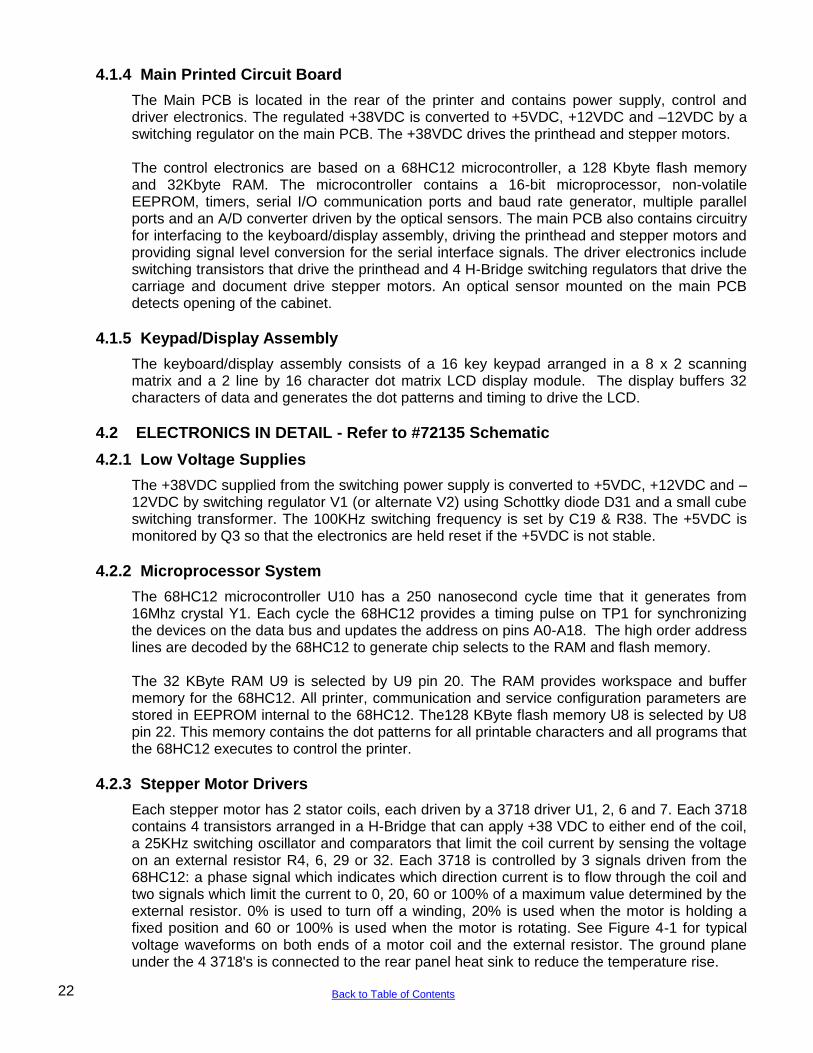
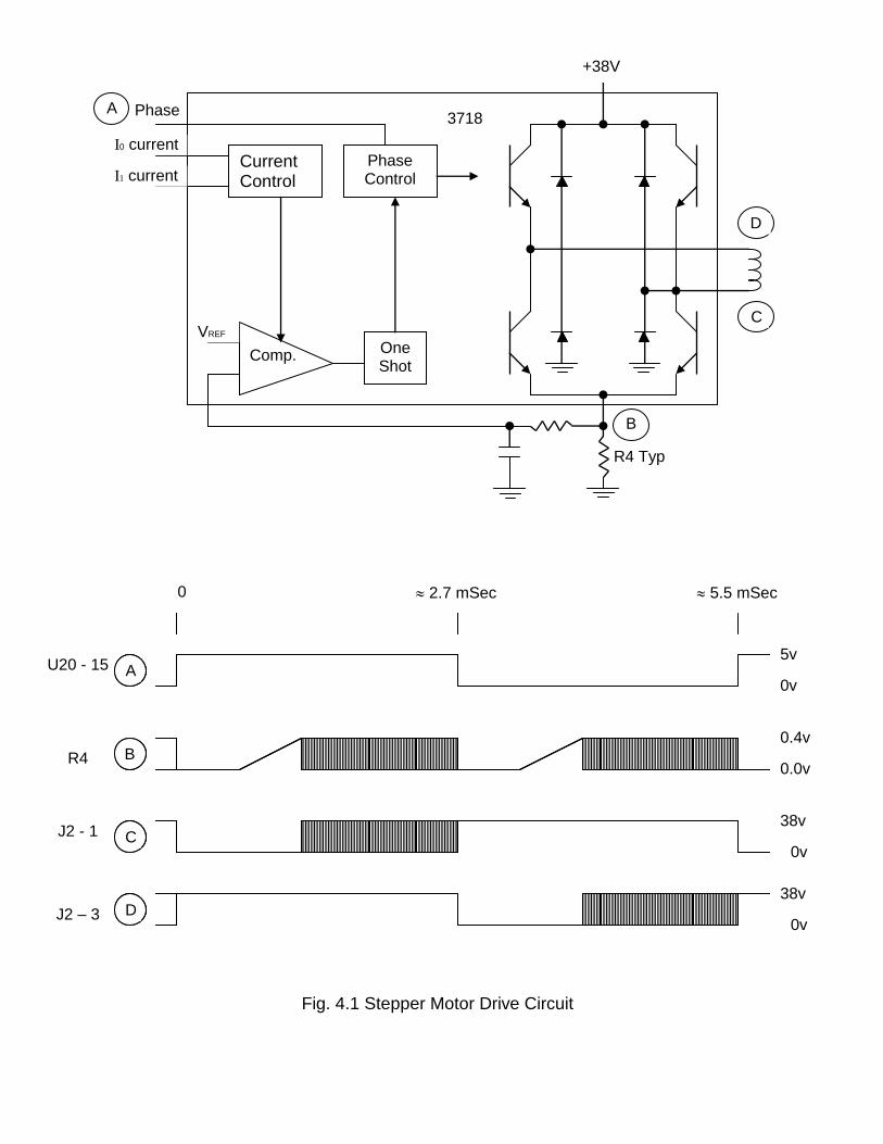
4.2.3 Stepper Motor Drivers
Each stepper motor has 2 stator coils, each driven by a 3718 driver U1, 2, 6 and 7. Each 3718 contains 4 transistors arranged in a H-Bridge that can apply +38 VDC to either end of the coil, a 25KHz switching oscillator and comparators that limit the coil current by sensing the voltage on an external resistor R4, 6, 29 or 32. Each 3718 is controlled by 3 signals driven from the 68HC12: a phase signal which indicates which direction current is to flow through the coil and two signals which limit the current to 0, 20, 60 or 100% of a maximum value determined by the external resistor. 0% is used to turn off a winding, 20% is used when the motor is holding a fixed position and 60 or 100% is used when the motor is rotating. See Figure 4-1 for typical voltage waveforms on both ends of a motor coil and the external resistor. The ground plane under the 4 3718's is connected to the rear panel heat sink to reduce the temperature rise.
22 Back to Table of Contents
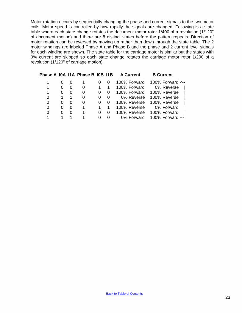
Motor rotation occurs by sequentially changing the phase and current signals to the two motor coils. Motor speed is controlled by how rapidly the signals are changed. Following is a state table where each state change rotates the document motor rotor 1/400 of a revolution (1/120" of document motion) and there are 8 distinct states before the pattern repeats. Direction of motor rotation can be reversed by moving up rather than down through the state table. The 2 motor windings are labeled Phase A and Phase B and the phase and 2 current level signals for each winding are shown. The state table for the carriage motor is similar but the states with 0% current are skipped so each state change rotates the carriage motor rotor 1/200 of a revolution (1/120" of carriage motion).
Phase A I0A I1A Phase B I0B I1B A Current B Current
1 0 0 1 0 0 100% Forward 100% Forward <-- 1 0 0 0 1 1 100% Forward 0% Reverse | 1 0 0 0 0 0 100% Forward 100% Reverse | 0 1 1 0 0 0 0% Reverse 100% Reverse | 0 0 0 0 0 0 100% Reverse 100% Reverse | 0 0 0 1 1 1 100% Reverse 0% Forward | 0 0 0 1 0 0 100% Reverse 100% Forward | 1 1 1 1 0 0 0% Forward 100% Forward ---
23 Back to Table of Contents
Current Control
Phase Control
One Shot
Comp.
3718
+38V
A
R4 Typ
Phase
I0 current
I1 current
VREF
0v
5v
0.4v
30v
30v
2.7 mSec 0 0
U20 - 15
R4
J2 - 1
J2 – 3
A
B
C
D
Fig. 4.1 Stepper Motor Drive Circuit
B
0v
5v
0.4v
30v
30v
2.7 mSec 0 0
U20 - 15
R4
J2 - 1
J2 – 3
A
B
C
D
0v
5v
0.0v
0.4v
0v
38v
38v
2.7 mSec 0 0 5.5 mSec
U20 - 15
R4
J2 - 1
J2 – 3
A
B
C
D 0v
C
D
4.2.4 Printhead Drivers
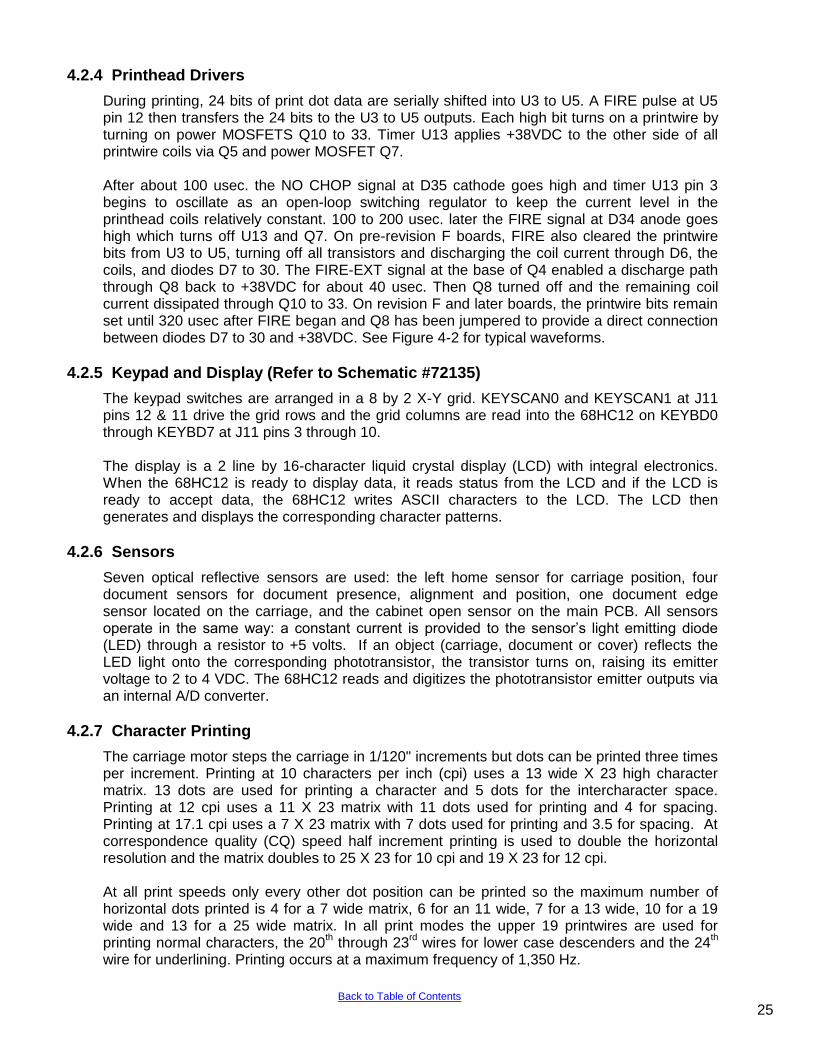
During printing, 24 bits of print dot data are serially shifted into U3 to U5. A FIRE pulse at U5 pin 12 then transfers the 24 bits to the U3 to U5 outputs. Each high bit turns on a printwire by turning on power MOSFETS Q10 to 33. Timer U13 applies +38VDC to the other side of all printwire coils via Q5 and power MOSFET Q7. After about 100 usec. the NO CHOP signal at D35 cathode goes high and timer U13 pin 3 begins to oscillate as an open-loop switching regulator to keep the current level in the printhead coils relatively constant. 100 to 200 usec. later the FIRE signal at D34 anode goes high which turns off U13 and Q7. On pre-revision F boards, FIRE also cleared the printwire bits from U3 to U5, turning off all transistors and discharging the coil current through D6, the coils, and diodes D7 to 30. The FIRE-EXT signal at the base of Q4 enabled a discharge path through Q8 back to +38VDC for about 40 usec. Then Q8 turned off and the remaining coil current dissipated through Q10 to 33. On revision F and later boards, the printwire bits remain set until 320 usec after FIRE began and Q8 has been jumpered to provide a direct connection between diodes D7 to 30 and +38VDC. See Figure 4-2 for typical waveforms.
4.2.5 Keypad and Display (Refer to Schematic #72135)
The keypad switches are arranged in a 8 by 2 X-Y grid. KEYSCAN0 and KEYSCAN1 at J11 pins 12 & 11 drive the grid rows and the grid columns are read into the 68HC12 on KEYBD0 through KEYBD7 at J11 pins 3 through 10. The display is a 2 line by 16-character liquid crystal display (LCD) with integral electronics. When the 68HC12 is ready to display data, it reads status from the LCD and if the LCD is ready to accept data, the 68HC12 writes ASCII characters to the LCD. The LCD then generates and displays the corresponding character patterns.
4.2.6 Sensors
Seven optical reflective sensors are used: the left home sensor for carriage position, four document sensors for document presence, alignment and position, one document edge sensor located on the carriage, and the cabinet open sensor on the main PCB. All sensors operate in the same way: a constant current is provided to the sensor‟s light emitting diode (LED) through a resistor to +5 volts. If an object (carriage, document or cover) reflects the LED light onto the corresponding phototransistor, the transistor turns on, raising its emitter voltage to 2 to 4 VDC. The 68HC12 reads and digitizes the phototransistor emitter outputs via an internal A/D converter.
4.2.7 Character Printing
The carriage motor steps the carriage in 1/120" increments but dots can be printed three times per increment. Printing at 10 characters per inch (cpi) uses a 13 wide X 23 high character matrix. 13 dots are used for printing a character and 5 dots for the intercharacter space. Printing at 12 cpi uses a 11 X 23 matrix with 11 dots used for printing and 4 for spacing. Printing at 17.1 cpi uses a 7 X 23 matrix with 7 dots used for printing and 3.5 for spacing. At correspondence quality (CQ) speed half increment printing is used to double the horizontal resolution and the matrix doubles to 25 X 23 for 10 cpi and 19 X 23 for 12 cpi. At all print speeds only every other dot position can be printed so the maximum number of horizontal dots printed is 4 for a 7 wide matrix, 6 for an 11 wide, 7 for a 13 wide, 10 for a 19 wide and 13 for a 25 wide matrix. In all print modes the upper 19 printwires are used for printing normal characters, the 20
th through 23
rd wires for lower case descenders and the 24
th
wire for underlining. Printing occurs at a maximum frequency of 1,350 Hz.
25 Back to Table of Contents
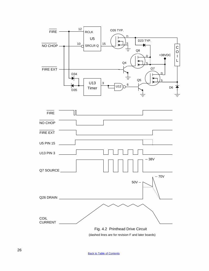
Fig. 4.2 Printhead Drive Circuit
D
S
D
S
D
S
C O I L
U13
Timer
U5
RCLK
SRCLR Q
Q26 TYP.
D23 TYP.
Q8
Q7
D6
Q5
Q4
U12 6
3
15
12
10
+38VDC
D34
D35
FIRE
NO CHOP
FIRE EXT
FIRE
NO CHOP
FIRE EXT
U5 PIN 15
U13 PIN 3
Q7 SOURCE
Q26 DRAIN
COIL CURRENT
50V --
-- 70V
-- 38V
(dashed lines are for revision F and later boards)
26 Back to Table of Contents
5.0 MAINTENANCE
5.1 LUBRICATION AND CLEANING
5.1.1 Lubrication
There are no lubrication points in the printer. All parts are either permanently lubricated or are designed to operate dry. No lubricants should be used. They may adversely affect operation.
5.1.2 Document Feed Roller Cleaning
1. Open the cabinet. 2. Moisten a lint-free cloth with isopropyl alcohol and wipe the front rollers while rotating the
gear on the end of the roller shaft. Do not use any strong solvents in place of alcohol. 3. In similar fashion, clean the rear rollers. Make sure all rollers are dry and free of residue.
5.1.3 Sensor Cleaning
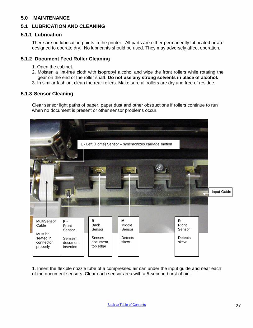
Clear sensor light paths of paper, paper dust and other obstructions if rollers continue to run when no document is present or other sensor problems occur.
1. Insert the flexible nozzle tube of a compressed air can under the input guide and near each of the document sensors. Clear each sensor area with a 5-second burst of air.
L - Left (Home) Sensor – synchronizes carriage motion
MultiSensor Cable Must be seated in connector properly
F - Front Sensor Senses document insertion
B - Back Sensor Senses document top edge
M -Middle Sensor Detects skew
R - Right Sensor Detects skew
Input Guide
27 Back to Table of Contents
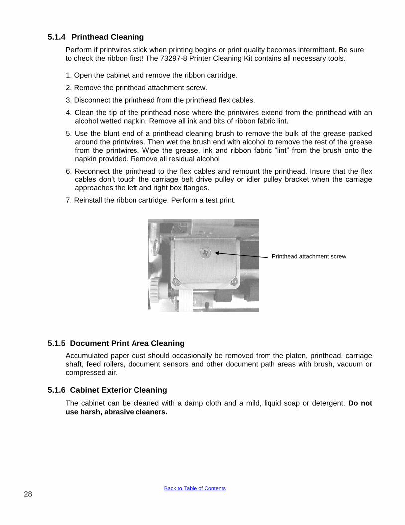
5.1.4 Printhead Cleaning
Perform if printwires stick when printing begins or print quality becomes intermittent. Be sure to check the ribbon first! The 73297-8 Printer Cleaning Kit contains all necessary tools.
1. Open the cabinet and remove the ribbon cartridge.
2. Remove the printhead attachment screw.
3. Disconnect the printhead from the printhead flex cables.
4. Clean the tip of the printhead nose where the printwires extend from the printhead with an alcohol wetted napkin. Remove all ink and bits of ribbon fabric lint.
5. Use the blunt end of a printhead cleaning brush to remove the bulk of the grease packed around the printwires. Then wet the brush end with alcohol to remove the rest of the grease from the printwires. Wipe the grease, ink and ribbon fabric “lint” from the brush onto the napkin provided. Remove all residual alcohol
6. Reconnect the printhead to the flex cables and remount the printhead. Insure that the flex cables don‟t touch the carriage belt drive pulley or idler pulley bracket when the carriage approaches the left and right box flanges.
7. Reinstall the ribbon cartridge. Perform a test print.
5.1.5 Document Print Area Cleaning
Accumulated paper dust should occasionally be removed from the platen, printhead, carriage shaft, feed rollers, document sensors and other document path areas with brush, vacuum or compressed air.
5.1.6 Cabinet Exterior Cleaning
The cabinet can be cleaned with a damp cloth and a mild, liquid soap or detergent. Do not
use harsh, abrasive cleaners.
DP8/9 carriage top view
Printhead attachment screw
28 Back to Table of Contents
5.2 SERVICE PARAMETER SET-UP PROCEDURE It may be necessary to change service parameters that compensate for certain mechanical tolerances. These parameters are listed on a label inside the printer and may be changed if necessary by 94 FUNCT(see 3.5.4). If mechanical parts are replaced some parameters may have to be reset. New parameter values should be marked on the configuration label.
The service parameters are determined by using 95 FUNCT local print and either 955 and 944
FUNCT or just 943 FUNCT as described below. Parameter values are changed with the A
and B keys. After changing a parameter, use 95, and either 955 and 944 or just 943, to obtain new print samples. Re-measure all distances and re-adjust if necessary.
TOP OFFSET is set so the distance from the top document edge to the center of the first line printed by 95 FUNCT is located as specified by LINE #1 = .XXX (.250 is the default factory setting) under 92 FUNCT.
LEFT OFFSET is set so the carriage can still move leftward from its home position 0.01" to 0.02" (0.3 to 0.5mm) before it contacts the gate arm that raises the alignment gate.
LEFT MARGIN is set so the distance from the left document edge to the left edge of the first character printed by 95 FUNCT is 0.20" (5.1mm) if edge sensing is not installed (EDGE SENSOR parameter will not appear below).
CAR ALIGN is set so either the vertical strokes of H‟s printed by 955 FUNCT (firmware E9 and earlier) from right to left align with those printed left to right or the zeros printed by 943 FUNCT (firmware EA and later) align. See 5.4.2 for precise adjustment but do not change the belt tension unless necessary.
FORWARD and REVERSE COMPENSATION are set using either 943 or 944 FUNCT:
a. Procedure for firmware E9 and earlier (see 3.7)
944 FUNCT prints lines of overlapping X's and O‟s 10" apart.
Set FORWARD COMPENSATION so that the distance between lines of X's is 10.00" (254mm) +/- 0.02” (0.5mm)
Set REVERSE COMPENSATION so that the line of O's printed at the top of the page overlaps the line of X's within 0.02” (0.5mm).
b. Procedure for firmware EA and later (see 3.7) 943 FUNCT prints line pairs with values of –4 through +4.
Set both FORWARD and REVERSE COMPENSATION with the value whose line pair is closest to 10.00" (254mm) +/- 0.02” (0.5mm)
EJECT HOLD OFFSET is set so that an ejected document is still held in the drive rollers but can be removed by pulling gently on it.
CONFIGURATION selects certain custom operating features and should not be set to a value other than shown on the configuration label without contacting the factory.
GATE OFFSET is set by the Auto Alignment Gate Height procedure (see 5.4.7)
EDGE SENSOR is set so the distance from the left document edge to the left edge of the first character printed by 95 FUNCT is 0.20" (5.1mm). This parameter is available on DP8 serial number 182057 and higher and DP9 serial number 293501 and higher.
NORMAL DARKNESS Lower values reduce darkness and increase ribbon life at normal print speed. Select the lowest value that provides suitable legibility on thick forms. CQ DARKNESS similarly controls darkness at correspondence quality print speed.
PRINTHEAD TYPE (early DP8 only) adjusts print pulse timing for two different printheads that have different drive characteristics. Select AUTO DETECT unless serial number is below 81000. Then select BLACK or SILVER printhead body color. A BLACK head can be damaged if set to SILVER.
5.3 ELECTRICAL ADJUSTMENTS There are no electrical adjustments required.
29 Back to Table of Contents
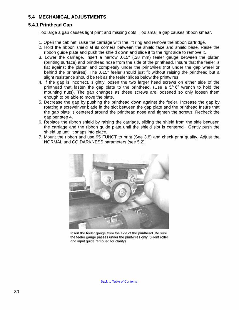
5.4 MECHANICAL ADJUSTMENTS
5.4.1 Printhead Gap
Too large a gap causes light print and missing dots. Too small a gap causes ribbon smear. 1. Open the cabinet, raise the carriage with the lift ring and remove the ribbon cartridge. 2. Hold the ribbon shield at its corners between the shield face and shield base. Raise the
ribbon guide plate and push the shield down and slide it to the right side to remove it. 3. Lower the carriage. Insert a narrow .015" (.38 mm) feeler gauge between the platen
(printing surface) and printhead nose from the side of the printhead. Insure that the feeler is flat against the platen and completely under the printwires (not under the gap wheel or behind the printwires). The .015" feeler should just fit without raising the printhead but a slight resistance should be felt as the feeler slides below the printwires.
4. If the gap is incorrect, slightly loosen the two larger head screws on either side of the printhead that fasten the gap plate to the printhead. (Use a 5/16” wrench to hold the mounting nuts). The gap changes as these screws are loosened so only loosen them enough to be able to move the plate.
5. Decrease the gap by pushing the printhead down against the feeler. Increase the gap by rotating a screwdriver blade in the slot between the gap plate and the printhead Insure that the gap plate is centered around the printhead nose and tighten the screws. Recheck the gap per step 4.
6. Replace the ribbon shield by raising the carriage, sliding the shield from the side between the carriage and the ribbon guide plate until the shield slot is centered. Gently push the shield up until it snaps into place.
7. Mount the ribbon and use 95 FUNCT to print (See 3.8) and check print quality. Adjust the NORMAL and CQ DARKNESS parameters (see 5.2).
Insert the feeler gauge from the side of the printhead. Be sure the feeler gauge passes under the printwires only. (Front roller and input guide removed for clarity)
30
Back to Table of Contents
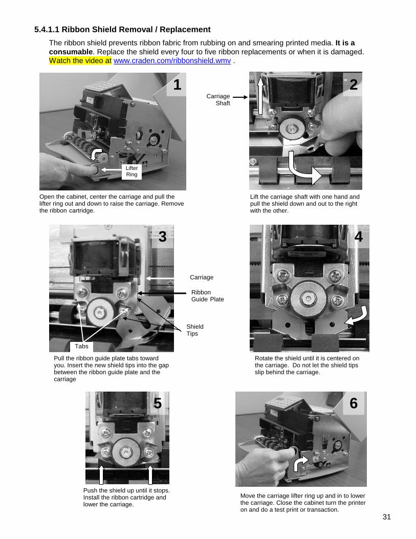
5.4.1.1 Ribbon Shield Removal / Replacement
The ribbon shield prevents ribbon fabric from rubbing on and smearing printed media. It is a
consumable. Replace the shield every four to five ribbon replacements or when it is damaged. Watch the video at www.craden.com/ribbonshield.wmv .
Open the cabinet, center the carriage and pull the lifter ring out and down to raise the carriage. Remove the ribbon cartridge.
Lifter Ring
Carriage Shaft
Lift the carriage shaft with one hand and pull the shield down and out to the right with the other.
Shield Tips
Pull the ribbon guide plate tabs toward you. Insert the new shield tips into the gap between the ribbon guide plate and the carriage
Ribbon Guide Plate
Carriage
Tabs
Rotate the shield until it is centered on the carriage. Do not let the shield tips slip behind the carriage.
Push the shield up until it stops. Install the ribbon cartridge and lower the carriage.
Move the carriage lifter ring up and in to lower the carriage. Close the cabinet turn the printer on and do a test print or transaction.
6 5
4 3
2 1
31
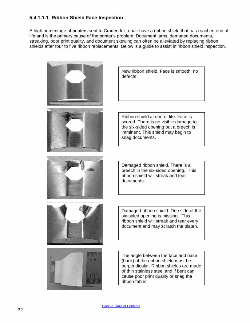
5.4.1.1.1 Ribbon Shield Face Inspection
A high percentage of printers sent to Craden for repair have a ribbon shield that has reached end of life and is the primary cause of the printer‟s problem. Document jams, damaged documents, streaking, poor print quality, and document skewing can often be alleviated by replacing ribbon shields after four to five ribbon replacements. Below is a guide to assist in ribbon shield inspection.
32
New ribbon shield. Face is smooth, no defects
Ribbon shield at end of life. Face is scored. There is no visible damage to the six-sided opening but a breech is imminent. This shield may begin to snag documents.
Damaged ribbon shield. There is a breech in the six-sided opening. This ribbon shield will streak and tear documents.
Damaged ribbon shield. One side of the six-sided opening is missing. This ribbon shield will streak and tear every document and may scratch the platen.
The angle between the face and base (back) of the ribbon shield must be perpendicular. Ribbon shields are made of thin stainless steel and if bent can cause poor print quality or snag the ribbon fabric.
Back to Table of Contents
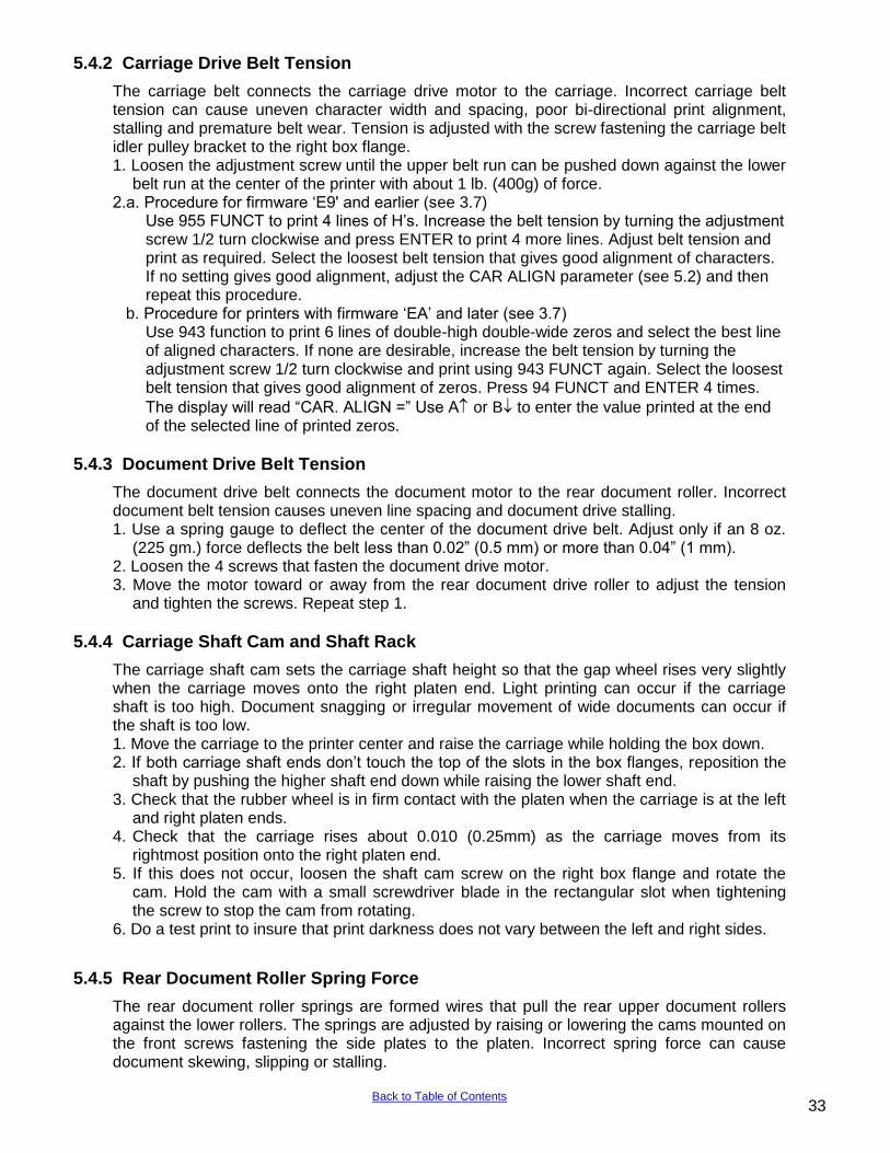
5.4.2 Carriage Drive Belt Tension
The carriage belt connects the carriage drive motor to the carriage. Incorrect carriage belt tension can cause uneven character width and spacing, poor bi-directional print alignment, stalling and premature belt wear. Tension is adjusted with the screw fastening the carriage belt idler pulley bracket to the right box flange. 1. Loosen the adjustment screw until the upper belt run can be pushed down against the lower
belt run at the center of the printer with about 1 lb. (400g) of force. 2.a. Procedure for firmware „E9' and earlier (see 3.7)
Use 955 FUNCT to print 4 lines of H‟s. Increase the belt tension by turning the adjustment screw 1/2 turn clockwise and press ENTER to print 4 more lines. Adjust belt tension and print as required. Select the loosest belt tension that gives good alignment of characters. If no setting gives good alignment, adjust the CAR ALIGN parameter (see 5.2) and then repeat this procedure.
b. Procedure for printers with firmware „EA‟ and later (see 3.7) Use 943 function to print 6 lines of double-high double-wide zeros and select the best line of aligned characters. If none are desirable, increase the belt tension by turning the adjustment screw 1/2 turn clockwise and print using 943 FUNCT again. Select the loosest belt tension that gives good alignment of zeros. Press 94 FUNCT and ENTER 4 times.
The display will read “CAR. ALIGN =” Use A or B to enter the value printed at the end of the selected line of printed zeros.
5.4.3 Document Drive Belt Tension
The document drive belt connects the document motor to the rear document roller. Incorrect document belt tension causes uneven line spacing and document drive stalling. 1. Use a spring gauge to deflect the center of the document drive belt. Adjust only if an 8 oz.
(225 gm.) force deflects the belt less than 0.02” (0.5 mm) or more than 0.04” (1 mm). 2. Loosen the 4 screws that fasten the document drive motor. 3. Move the motor toward or away from the rear document drive roller to adjust the tension
and tighten the screws. Repeat step 1.
5.4.4 Carriage Shaft Cam and Shaft Rack
The carriage shaft cam sets the carriage shaft height so that the gap wheel rises very slightly when the carriage moves onto the right platen end. Light printing can occur if the carriage shaft is too high. Document snagging or irregular movement of wide documents can occur if the shaft is too low. 1. Move the carriage to the printer center and raise the carriage while holding the box down. 2. If both carriage shaft ends don‟t touch the top of the slots in the box flanges, reposition the
shaft by pushing the higher shaft end down while raising the lower shaft end. 3. Check that the rubber wheel is in firm contact with the platen when the carriage is at the left
and right platen ends. 4. Check that the carriage rises about 0.010 (0.25mm) as the carriage moves from its
rightmost position onto the right platen end. 5. If this does not occur, loosen the shaft cam screw on the right box flange and rotate the
cam. Hold the cam with a small screwdriver blade in the rectangular slot when tightening the screw to stop the cam from rotating.
6. Do a test print to insure that print darkness does not vary between the left and right sides.
5.4.5 Rear Document Roller Spring Force
The rear document roller springs are formed wires that pull the rear upper document rollers against the lower rollers. The springs are adjusted by raising or lowering the cams mounted on the front screws fastening the side plates to the platen. Incorrect spring force can cause document skewing, slipping or stalling.
33 Back to Table of Contents
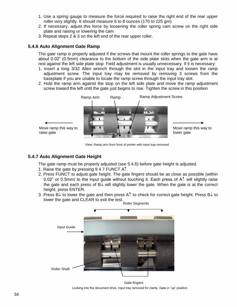
1. Use a spring gauge to measure the force required to raise the right end of the rear upper roller very slightly. It should measure 6 to 8 ounces (170 to 225 gm).
2. If necessary, adjust this force by loosening the roller spring cam screw on the right side plate and raising or lowering the cam.
3. Repeat steps 2 & 3 on the left end of the rear upper roller.
5.4.6 Auto Alignment Gate Ramp
The gate ramp is properly adjusted if the screws that mount the roller springs to the gate have about 0.02” (0.5mm) clearance to the bottom of the side plate slots when the gate arm is at rest against the left side plate stop. Field adjustment is usually unnecessary. If it is necessary: 1. Insert a long 3/32 Allen wrench through the slot in the input tray and loosen the ramp
adjustment screw. The input tray may be removed by removing 3 screws from the baseplate if you are unable to locate the ramp screw through the input tray slot.
2. Hold the ramp arm against the stop on the left side plate and move the ramp adjustment screw toward the left until the gate just begins to rise. Tighten the screw in this position
5.4.7 Auto Alignment Gate Height
The gate ramp must be properly adjusted (see 5.4.6) before gate height is adjusted.
1. Raise the gate by pressing 9 4 7 FUNCT A. 2. Press FUNCT to adjust gate height. The gate fingers should be as close as possible (within
0.02” or 0.5mm) to the input guide without touching it. Each press of A will slightly raise
the gate and each press of B will slightly lower the gate. When the gate is at the correct height, press ENTER.
3. Press B to lower the gate and then press A to check for correct gate height. Press B to lower the gate and CLEAR to exit the test.
Move ramp this way to lower gate
View: Ramp arm from front of printer with input tray removed
Move ramp this way to raise gate
Ramp Arm Ramp Ramp Adjustment Screw
Roller Segments
Roller Shaft
Input Guide
Gate fingers
Looking into the document drive. Input tray removed for clarity. Gate in “up” position
34
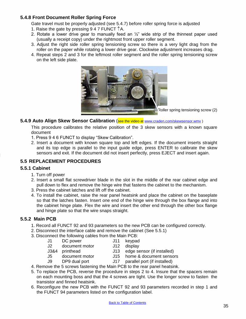
5.4.8 Front Document Roller Spring Force
Gate travel must be properly adjusted (see 5.4.7) before roller spring force is adjusted
1. Raise the gate by pressing 9 4 7 FUNCT A. 2. Rotate a lower drive gear to manually feed an ½” wide strip of the thinnest paper used
(usually a receipt copy) under the rightmost front upper roller segment. 3. Adjust the right side roller spring tensioning screw so there is a very light drag from the
roller on the paper while rotating a lower drive gear. Clockwise adjustment increases drag. 4. Repeat steps 2 and 3 for the leftmost roller segment and the roller spring tensioning screw
on the left side plate.
5.4.9 Auto Align Skew Sensor Calibration (see the video at www.craden.com/skewsensor.wmv )
This procedure calibrates the relative position of the 3 skew sensors with a known square document 1. Press 9 4 6 FUNCT to display “Skew Calibration”. 2. Insert a document with known square top and left edges. If the document inserts straight
and its top edge is parallel to the input guide edge, press ENTER to calibrate the skew sensors and exit. If the document did not insert perfectly, press EJECT and insert again.
5.5 REPLACEMENT PROCEDURES
5.5.1 Cabinet
1. Turn off power 2. Insert a small flat screwdriver blade in the slot in the middle of the rear cabinet edge and
pull down to flex and remove the hinge wire that fastens the cabinet to the mechanism. 3. Press the cabinet latches and lift off the cabinet. 4. To install the cabinet, raise the rear panel heatsink and place the cabinet on the baseplate
so that the latches fasten. Insert one end of the hinge wire through the box flange and into the cabinet hinge plate. Flex the wire and insert the other end through the other box flange and hinge plate so that the wire snaps straight.
5.5.2 Main PCB
1. Record all FUNCT 92 and 93 parameters so the new PCB can be configured correctly. 2. Disconnect the interface cable and remove the cabinet (See 5.5.1) 3. Disconnect the following cables from the Main PCB: J1 DC power J11 keypad J2 document motor J12 display J3&4 printhead J13 edge sensor (if installed) J5 document motor J15 home & document sensors J9 DP9 dual port J17 parallel port (if installed) 4. Remove the 5 screws fastening the Main PCB to the rear panel heatsink. 5. To replace the PCB, reverse the procedure in steps 2 to 4. Insure that the spacers remain
on each mounting boss and that the 4 screws are tight. Use the longer screw to fasten the transistor and finned heatsink.
6. Reconfigure the new PCB with the FUNCT 92 and 93 parameters recorded in step 1 and the FUNCT 94 parameters listed on the configuration label.
Roller spring tensioning screw (2)
35 Back to Table of Contents
5.5.3 Sensor PCB
1. Turn off power and disconnect the flex cable from the sensor PCB. 3. Remove the two nuts fastening the PCB to the input guide. 4. Raise the upper front roller and remove the PCB by pushing it to the rear. 5. Install the lower (thick) sensor insulator, the new PCB and the upper (thin) sensor insulator. 6. Push the PCB and insulators forward, fasten the nuts and reconnect the flex cable. 7. Adjust TOP, LEFT OFFSET, LEFT MARGIN and EJECT HOLD parameters so that inserted
documents are correctly positioned (See 5.2). Record new values on the parameter label. 8. Calibrate the skew sensor (See 5.4.9).
5.5.4 Keypad
1. Turn off power and remove the cabinet (See 5.5.1). 2. Place the mechanism upside down so it rests on the box and keypad bracket. 3. Remove the nuts fastening the keypad to the bracket. 4. Disconnect the flex cable and remove the keypad. 5. To install a new keypad reverse the procedure in steps 1 to 4
5.5.5 Display
1. Turn off power and remove the cabinet (See 5.5.1). 2. Place the mechanism upside down so it rests on the box and keypad bracket. 3. Remove the nuts fastening the display to the bracket. 4. Pull the flex cable connector cover away from the connector to disconnect the flex cable. 5. To install a new display reverse the procedure in steps 1 to 4
5.5.6 Power Supply PCB
1. Disconnect the AC power cord and remove the cabinet (see 5.5.1) 2. Raise the insulator flap covering the Power Supply PCB and disconnect the AC and DC
connectors from the PCB. 3. Remove the 4 screws fastening the PCB to the box and remove the PCB. 4. Position the mechanism so that it rests on the keypad bracket and input tray. 5. Put the screws into the new PCB. 6. Insure that the insulator stays located around each mounting boss while mounting the new
PCB and fasten the screws. 7. Reconnect the AC and DC connectors (the AC connector mounts to the end of the header
labeled “L” on the PCB). 8. Insure that the insulator flap separates the power supply from the flex cables.
5.5.7 Carriage Motor
1. Remove the cabinet (see 5.5.1). 2. Disconnect the carriage motor from J5 of the Main PCB. 3. Remove 3 screws from the motor (shaft side) that fasten it to the box. Guide the carriage
belt off the motor pulley (do not loosen the belt tensioner or you will have to readjust it) and remove the motor.
4. Transfer the motor pulley to the new motor. Leave a .01" (0.2mm) gap between the pulley hub and the motor flange.
5. Install the new motor in the box, onto the carriage drive belt, and fasten with the 3 screws. 6. Connect the motor to J5 on the Main PCB and replace the cabinet. 7. Set the LEFT HOME, LEFT MARGIN and CAR ALIGN parameters (see 5.2). 8. Tension the carriage belt (see 5.4.2).
36 Back to Table of Contents
5.5.8 Document Motor
1. Remove the cabinet (see 5.5.1). 2. Disconnect the motor from J2 on the Main PCB. 3. Loosen the 1/16” Allen screw that fastens the document drive pulley to the motor shaft 4. Remove the motor mounting screws. Remove the drive pulley through the motor clearance
hole in the right box wall and remove the motor from the side plate. 5. Install the new motor (leads exiting from the bottom) through the side plate and onto the
drive pulley and belt. It is easiest to replace the motor mounting screws by holding them with pliers between the side plate and box wall and then fastening them with a screwdriver inserted through holes in the box wall.
6. Locate the drive pulley so it is in line with the driven pulley and fasten it to the motor shaft. 7. Tension the belt (see 5.4.3). 8. Connect the motor to J2 on the Main PCB and replace the cabinet.
5.5.9 Printhead
1. If a black bodied printhead is to be installed in a DP8, run 9 0 FUNCT to display the firmware revision which MUST be C1 or greater. A DP8 with A or B series firmware MUST be upgraded to at least C1 before a black bodied printhead can be used.
2. Open the cabinet, raise the carriage with the lift ring and remove the ribbon cartridge. 3. Hold the ribbon shield at its corners between the shield face and shield base. Raise the
ribbon guide plate and push the shield down and slide it to the right side to remove it. See picture in 5.4.1
4. Remove the printhead attachment screw. See picture in 5.1.4. 5. Disconnect the printhead from the printhead flex cables. 6. Connect the new printhead to the flex cables and remount it. Insure that the flex cables
don‟t touch the carriage belt drive pulley or idler pulley bracket when the carriage approaches the left and right box flanges.
7. If possible, reset the printhead gap (see 5.4.1). 8. Replace the ribbon shield and cartridge. 9. For DP8‟s only, run 9 4 FUNCT. If the PRINTHEAD TYPE parameter appears after CQ
DARKNESS, set it to match the printhead body color. A BLACK head can be damaged if set to SILVER.
10. Adjust LEFT OFFSET, NORMAL and CQ DARKNESS (see 5.2).
5.5.10 Carriage Drive Belt
1. Loosen the screw fastening the belt clamp to the carriage and remove the belt clamp. 2. Remove the screw fastening the carriage belt idler pulley to the right box flange. The belt
and idler pulley are replaced as an assembly. 3. Install the new belt and clamp it to the carriage. 4. Tension the carriage belt (see 5.4.2). 5. Set the LEFT OFFSET, LEFT MARGIN and CAR ALIGN parameters (see 5.2).
5.5.11 Document Drive Belt
1. Loosen the document motor mounting screws and push the motor toward the drive rollers. 2. Slide the belt off the rear roller pulley and remove the belt. 3. Install the new belt through the motor clearance hole in the right box wall and re-tension the
belt (see 5.4.3).
37
Back to Table of Contents
5.6 TROUBLESHOOTING
5.6.1 Basic Troubleshooting
This procedure exercises everything in the printer except the interface to the host system. If any step is not successfully executed, refer to the corresponding troubleshooting section.
1. Turn on printer power. A) If nothing appears on the display, see 5.6.2.
B) If < > BAD is displayed, replace the indicated component on the main PCB or the complete main PCB. C) If CARRIAGE FAULT is displayed, see 5.6.6.
2. Press 12345678 and then CLEAR. Each number should appear in the display and then all
should disappear. If this does not occur or if diagnostics don't begin to execute in the next step, see 5.6.3.
3. Execute 90 FUNCT diagnostics (see 3.6.2) and exercise the 7 sensors. If any sensor does
not operate, see 5.6.4. 4. Execute Local Printing (see 3.8) and use a 6" x 11" document. A) If a document will not load into the printer, see 5.6.5. B) If the carriage will not move across the document, see 5.6.6. C) If no printing occurs, see 5.6.7. D) If print quality is not acceptable, see 5.6.8. E) For other possible problems, see 5.6.9. through 5.6.12
5.6.2 No Display
If nothing appears on the display on power up, check that: 1. The power switch on rear of printer is ON. 2. The input power cord is plugged into both printer and supply outlet. 3. The contrast knob to the left of the configuration label is set for good display contrast. 4. Input power is present on the input power cord. 5. The fuse on the Power Supply PCB is good. 6. The display cable is attached to the display and to the main PCB J11. 7. 38 VDC is present between main PCB J1 pins 1 and 5. If not, check for AC line voltage at
the Power Supply PCB input. If AC is present but 38VDC is not, replace the Power Supply. 9. If 38 VDC is present replace either the main PCB or the display module.
5.6.3 Defective Keypad
If keypad depressions are not sensed proceed as follows: 1. If a single key fails but all others are OK, just that key may be replaced after the keypad is
removed (see 5.5.4). 2. If a row or column of keys all fail, a key may be permanently depressed or the problem is in
the cable between the main PCB and the keypad or on the main PCB.
38 Back to Table of Contents
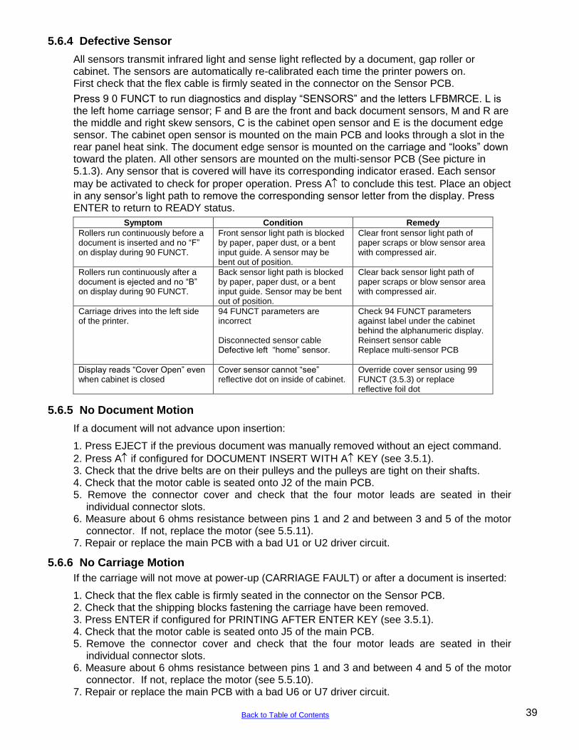
5.6.4 Defective Sensor
All sensors transmit infrared light and sense light reflected by a document, gap roller or cabinet. The sensors are automatically re-calibrated each time the printer powers on. First check that the flex cable is firmly seated in the connector on the Sensor PCB.
Press 9 0 FUNCT to run diagnostics and display “SENSORS” and the letters LFBMRCE. L is the left home carriage sensor; F and B are the front and back document sensors, M and R are the middle and right skew sensors, C is the cabinet open sensor and E is the document edge sensor. The cabinet open sensor is mounted on the main PCB and looks through a slot in the rear panel heat sink. The document edge sensor is mounted on the carriage and “looks” down toward the platen. All other sensors are mounted on the multi-sensor PCB (See picture in 5.1.3). Any sensor that is covered will have its corresponding indicator erased. Each sensor
may be activated to check for proper operation. Press A to conclude this test. Place an object in any sensor‟s light path to remove the corresponding sensor letter from the display. Press ENTER to return to READY status.
Symptom Condition Remedy
Rollers run continuously before a document is inserted and no “F” on display during 90 FUNCT.
Front sensor light path is blocked by paper, paper dust, or a bent input guide. A sensor may be bent out of position.
Clear front sensor light path of paper scraps or blow sensor area with compressed air.
Rollers run continuously after a document is ejected and no “B” on display during 90 FUNCT.
Back sensor light path is blocked by paper, paper dust, or a bent input guide. Sensor may be bent out of position.
Clear back sensor light path of paper scraps or blow sensor area with compressed air.
Carriage drives into the left side of the printer.
94 FUNCT parameters are incorrect Disconnected sensor cable Defective left “home” sensor.
Check 94 FUNCT parameters against label under the cabinet behind the alphanumeric display. Reinsert sensor cable Replace multi-sensor PCB
Display reads “Cover Open” even when cabinet is closed
Cover sensor cannot “see” reflective dot on inside of cabinet.
Override cover sensor using 99 FUNCT (3.5.3) or replace reflective foil dot
5.6.5 No Document Motion
If a document will not advance upon insertion:
1. Press EJECT if the previous document was manually removed without an eject command.
2. Press A if configured for DOCUMENT INSERT WITH A KEY (see 3.5.1). 3. Check that the drive belts are on their pulleys and the pulleys are tight on their shafts. 4. Check that the motor cable is seated onto J2 of the main PCB. 5. Remove the connector cover and check that the four motor leads are seated in their
individual connector slots. 6. Measure about 6 ohms resistance between pins 1 and 2 and between 3 and 5 of the motor
connector. If not, replace the motor (see 5.5.11). 7. Repair or replace the main PCB with a bad U1 or U2 driver circuit.
5.6.6 No Carriage Motion
If the carriage will not move at power-up (CARRIAGE FAULT) or after a document is inserted:
1. Check that the flex cable is firmly seated in the connector on the Sensor PCB. 2. Check that the shipping blocks fastening the carriage have been removed. 3. Press ENTER if configured for PRINTING AFTER ENTER KEY (see 3.5.1). 4. Check that the motor cable is seated onto J5 of the main PCB. 5. Remove the connector cover and check that the four motor leads are seated in their
individual connector slots. 6. Measure about 6 ohms resistance between pins 1 and 3 and between 4 and 5 of the motor
connector. If not, replace the motor (see 5.5.10). 7. Repair or replace the main PCB with a bad U6 or U7 driver circuit.
39 Back to Table of Contents
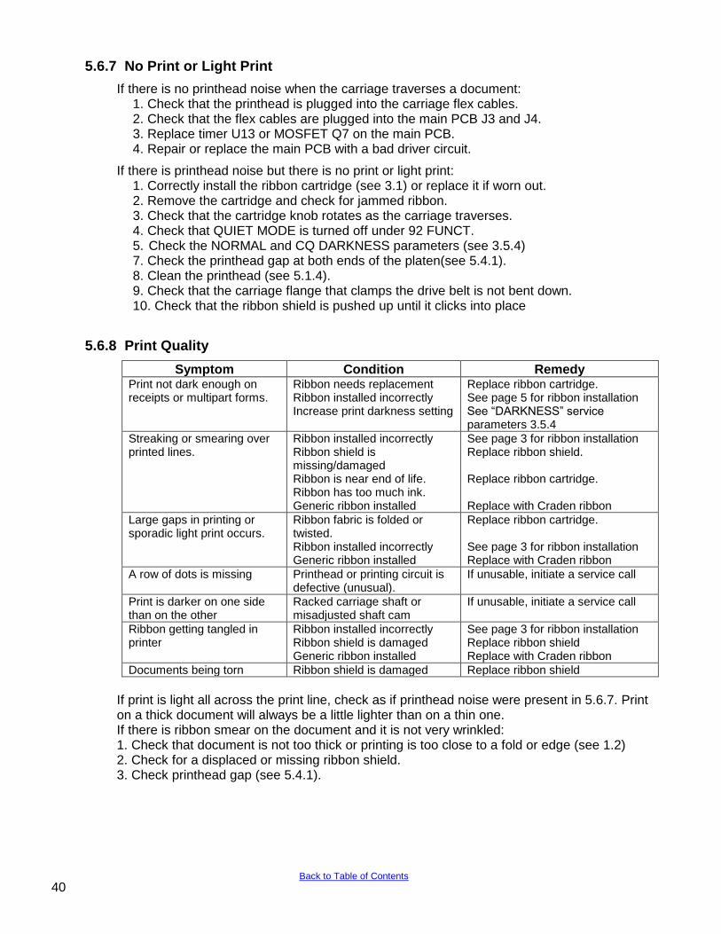
5.6.7 No Print or Light Print
If there is no printhead noise when the carriage traverses a document: 1. Check that the printhead is plugged into the carriage flex cables. 2. Check that the flex cables are plugged into the main PCB J3 and J4. 3. Replace timer U13 or MOSFET Q7 on the main PCB. 4. Repair or replace the main PCB with a bad driver circuit.
If there is printhead noise but there is no print or light print: 1. Correctly install the ribbon cartridge (see 3.1) or replace it if worn out. 2. Remove the cartridge and check for jammed ribbon. 3. Check that the cartridge knob rotates as the carriage traverses. 4. Check that QUIET MODE is turned off under 92 FUNCT. 5. Check the NORMAL and CQ DARKNESS parameters (see 3.5.4) 7. Check the printhead gap at both ends of the platen(see 5.4.1).
8. Clean the printhead (see 5.1.4). 9. Check that the carriage flange that clamps the drive belt is not bent down. 10. Check that the ribbon shield is pushed up until it clicks into place
5.6.8 Print Quality
Symptom Condition Remedy Print not dark enough on receipts or multipart forms.
Ribbon needs replacement Ribbon installed incorrectly Increase print darkness setting
Replace ribbon cartridge. See page 5 for ribbon installation See “DARKNESS” service parameters 3.5.4
Streaking or smearing over printed lines.
Ribbon installed incorrectly Ribbon shield is missing/damaged Ribbon is near end of life. Ribbon has too much ink. Generic ribbon installed
See page 3 for ribbon installation Replace ribbon shield. Replace ribbon cartridge. Replace with Craden ribbon
Large gaps in printing or sporadic light print occurs.
Ribbon fabric is folded or twisted. Ribbon installed incorrectly Generic ribbon installed
Replace ribbon cartridge. See page 3 for ribbon installation Replace with Craden ribbon
A row of dots is missing Printhead or printing circuit is defective (unusual).
If unusable, initiate a service call
Print is darker on one side than on the other
Racked carriage shaft or misadjusted shaft cam
If unusable, initiate a service call
Ribbon getting tangled in printer
Ribbon installed incorrectly Ribbon shield is damaged Generic ribbon installed
See page 3 for ribbon installation Replace ribbon shield Replace with Craden ribbon
Documents being torn Ribbon shield is damaged Replace ribbon shield
If print is light all across the print line, check as if printhead noise were present in 5.6.7. Print on a thick document will always be a little lighter than on a thin one. If there is ribbon smear on the document and it is not very wrinkled: 1. Check that document is not too thick or printing is too close to a fold or edge (see 1.2) 2. Check for a displaced or missing ribbon shield. 3. Check printhead gap (see 5.4.1).
40 Back to Table of Contents
5.6.9 Missing Dots
If a single row of dots is missing: 1. Refer to the printwire pinouts on the main PCB schematic. Pin 4 prints the uppermost dots
of uppercase characters, pins 20 through 23 print lower case descenders (g,j,p,q and y) and pin 24 prints underscores. Disconnect the flex cable from the main PCB and measure the resistance of the bad printwire through the cable. It should be approximately 12 ohms for a silver body printhead and 6 ohms for a black body printhead. If it is not, remove the printhead from the carriage and measure resistance at the printhead. If it is OK, replace the flex cable. If it is not, replace the printhead.
2. Repair or replace the main PCB with bad driver transistor Q11 through Q33. 3. The printhead may be mechanically faulty with a bent or jammed wire. Replace the
printhead.
5.6.10 Erratic Document Feed or Mispositioning
If feeding is erratic or preprinted forms are not correctly positioned: 1. Check for correct LINES/INCH and LINE #1(see 3.5.1). 2. Check that all service parameters are correctly set (see 5.2). 3. Check that the upper feed rollers move freely in the side plate slots. 4. Check that all belt drive pulleys are tight on their shafts. 5. Check the document drive belt tension (see 5.4.3). 6. Check that the roller springs are properly adjusted (See 5.4.5 and 5.4.8).
5.6.11 Erratic Character Spacing or False Document Jams
If horizontal character spacing is erratic or preprinted forms are not correctly printed: 1. Check for correct CHARACTERS/INCH settings (see 3.5.1). 2. Check that the carriage moves freely by hand. 3. If the carriage shaft shows any residue build-up, wipe it clean with a soft, dry cloth. 4. Check the carriage belt tension (see 5.4.2). 5. Tighten the drive pulley set screw on the carriage motor shaft.
5.6.12 Interface Inoperative
If the printer works in self test, but won't run from the interface:
1. Check that the I/O cable is correct for your application (see 3.11.3) 2. Check for firm mounting of the interface cable. 3. Check for communication parameters set to match the host system (see 3.5.2). 4. Check for correct interface wiring (see 3.11.3). 5. Press 9 4 2 then FUNCT to print all previously received data immediately after the
transaction. Control characters print as underlined lower case. 6. Check that CTS on I/O pin 7 is either not connected or is driven above +3V. 7. Replace the interface circuits in main PCB U14 and U15.
41 Back to Table of Contents
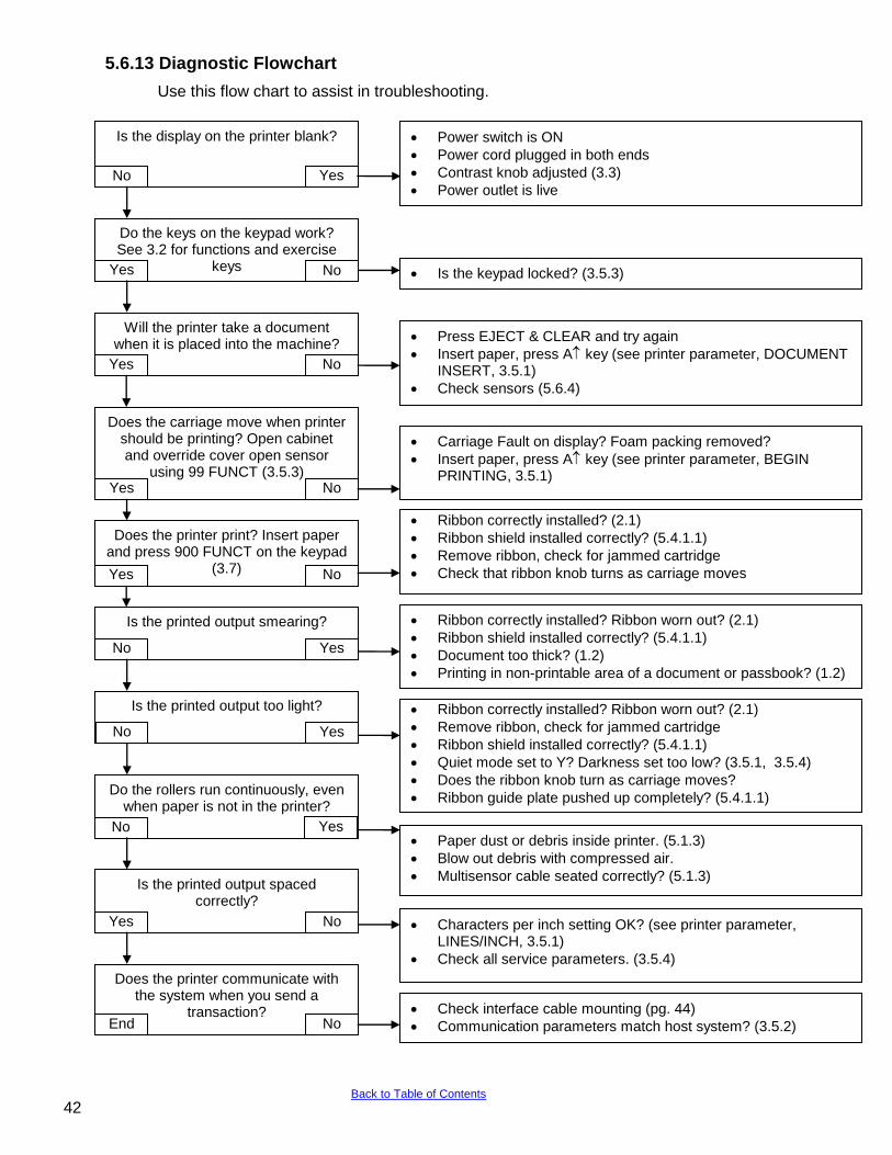
5.6.13 Diagnostic Flowchart
Use this flow chart to assist in troubleshooting.
Is the display on the printer blank? No Yes
Do the keys on the keypad work? See 3.2 for functions and exercise
keys
Yes No
Will the printer take a document when it is placed into the machine?
Yes No
Does the carriage move when printer should be printing? Open cabinet and override cover open sensor
using 99 FUNCT (3.5.3)
Yes No
Does the printer print? Insert paper and press 900 FUNCT on the keypad
(3.7)
Yes No
Do the rollers run continuously, even when paper is not in the printer?
Yes No
Is the printed output spaced correctly?
Yes No
Does the printer communicate with the system when you send a
transaction?
End No
Press EJECT & CLEAR and try again
Insert paper, press A key (see printer parameter, DOCUMENT INSERT, 3.5.1)
Check sensors (5.6.4)
Is the printed output smearing?
No Yes
Power switch is ON
Power cord plugged in both ends
Contrast knob adjusted (3.3)
Power outlet is live
Carriage Fault on display? Foam packing removed?
Insert paper, press A key (see printer parameter, BEGIN PRINTING, 3.5.1)
Is the printed output too light?
No Yes
Ribbon correctly installed? (2.1)
Ribbon shield installed correctly? (5.4.1.1)
Remove ribbon, check for jammed cartridge
Check that ribbon knob turns as carriage moves
Ribbon correctly installed? Ribbon worn out? (2.1)
Remove ribbon, check for jammed cartridge
Ribbon shield installed correctly? (5.4.1.1)
Quiet mode set to Y? Darkness set too low? (3.5.1, 3.5.4)
Does the ribbon knob turn as carriage moves?
Ribbon guide plate pushed up completely? (5.4.1.1)
Ribbon correctly installed? Ribbon worn out? (2.1)
Ribbon shield installed correctly? (5.4.1.1)
Document too thick? (1.2)
Printing in non-printable area of a document or passbook? (1.2)
Paper dust or debris inside printer. (5.1.3)
Blow out debris with compressed air.
Multisensor cable seated correctly? (5.1.3)
Check interface cable mounting (pg. 44)
Communication parameters match host system? (3.5.2)
Is the keypad locked? (3.5.3)
Characters per inch setting OK? (see printer parameter, LINES/INCH, 3.5.1)
Check all service parameters. (3.5.4)
42 Back to Table of Contents
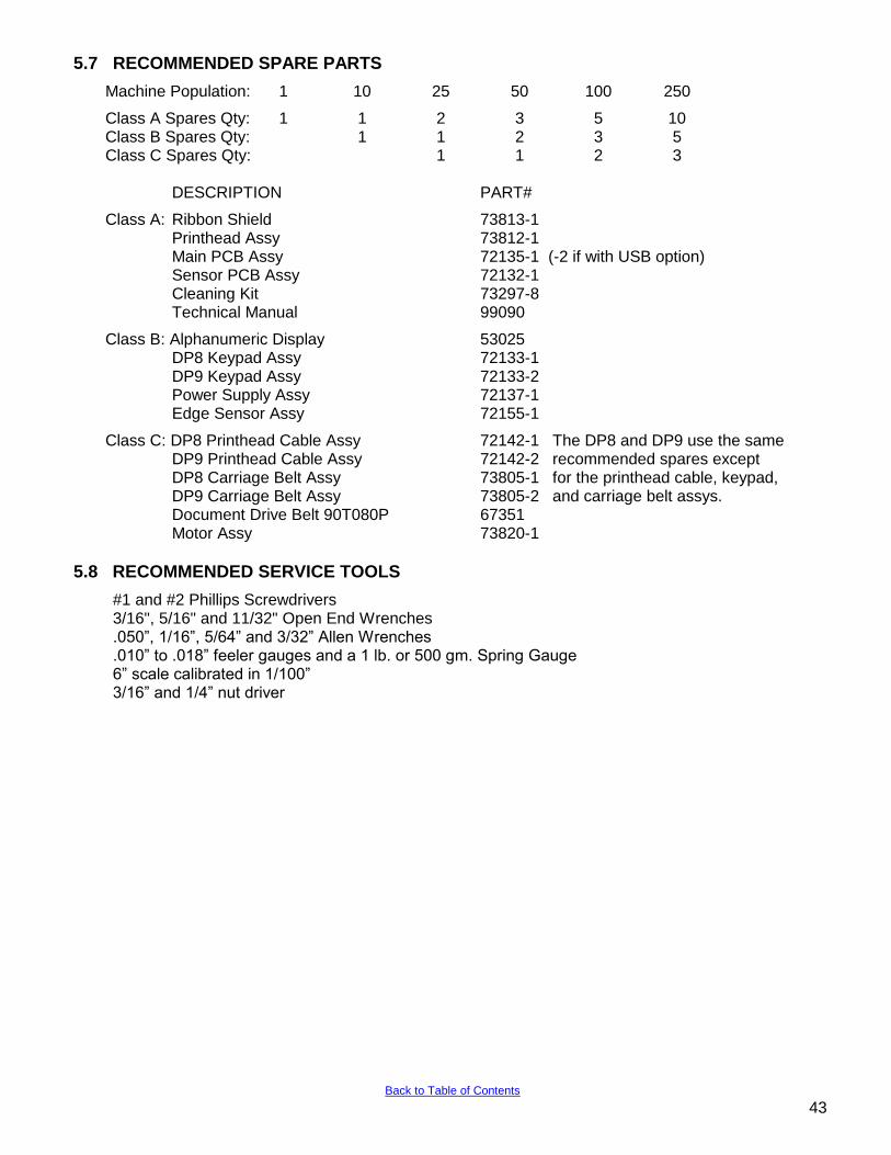
5.7 RECOMMENDED SPARE PARTS
Machine Population: 1 10 25 50 100 250
Class A Spares Qty: 1 1 2 3 5 10 Class B Spares Qty: 1 1 2 3 5 Class C Spares Qty: 1 1 2 3 DESCRIPTION PART#
Class A: Ribbon Shield 73813-1 Printhead Assy 73812-1 Main PCB Assy 72135-1 (-2 if with USB option) Sensor PCB Assy 72132-1 Cleaning Kit 73297-8 Technical Manual 99090
Class B: Alphanumeric Display 53025 DP8 Keypad Assy 72133-1 DP9 Keypad Assy 72133-2 Power Supply Assy 72137-1 Edge Sensor Assy 72155-1
Class C: DP8 Printhead Cable Assy 72142-1 The DP8 and DP9 use the same DP9 Printhead Cable Assy 72142-2 recommended spares except DP8 Carriage Belt Assy 73805-1 for the printhead cable, keypad, DP9 Carriage Belt Assy 73805-2 and carriage belt assys. Document Drive Belt 90T080P 67351 Motor Assy 73820-1
5.8 RECOMMENDED SERVICE TOOLS
#1 and #2 Phillips Screwdrivers 3/16", 5/16" and 11/32" Open End Wrenches .050”, 1/16”, 5/64” and 3/32” Allen Wrenches .010” to .018” feeler gauges and a 1 lb. or 500 gm. Spring Gauge 6” scale calibrated in 1/100” 3/16” and 1/4” nut driver
43 Back to Table of Contents
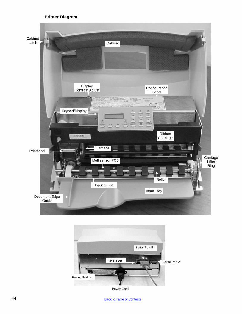
Printer Diagram
Cabinet
Keypad/Display
Configuration Label
Ribbon Cartridge
Input Tray
Document Edge Guide
Printhead Carriage
Input Guide
Roller
Carriage Lifter Ring
Multisensor PCB
Display Contrast Adjust
Cabinet Latch
Power Cord
Serial Port B
USB Port Serial Port A
Power Switch
44 Back to Table of Contents
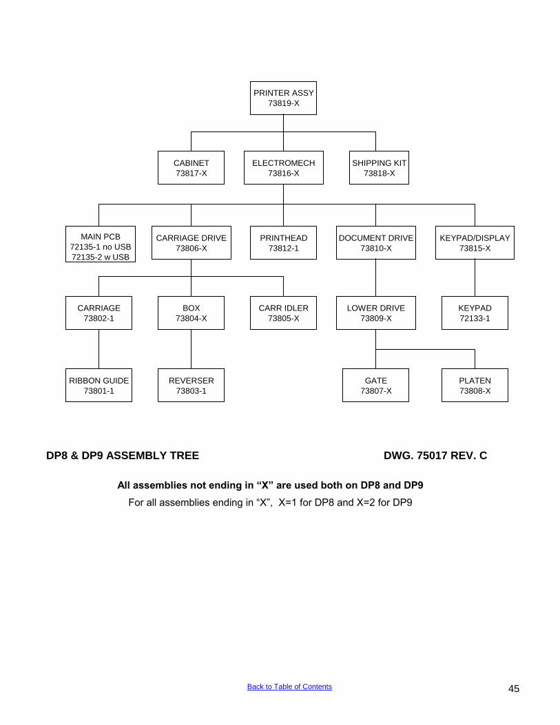
DP8 & DP9 ASSEMBLY TREE DWG. 75017 REV. C
All assemblies not ending in “X” are used both on DP8 and DP9
For all assemblies ending in “X”, X=1 for DP8 and X=2 for DP9
PRINTER ASSY
73819-X
LOWER DRIVE
73809-X
PLATEN
73808-X
GATE
73807-X
MAIN PCB
72135-1 no USB
72135-2 w USB
DOCUMENT DRIVE
73810-X
PRINTHEAD
73812-1
KEYPAD/DISPLAY
73815-X
ELECTROMECH
73816-X
SHIPPING KIT
73818-X
CABINET
73817-X
CARR IDLER
73805-X
RIBBON GUIDE
73801-1
REVERSER
73803-1
BOX
73804-X
CARRIAGE
73802-1
CARRIAGE DRIVE
73806-X
KEYPAD
72133-1
45 Back to Table of Contents
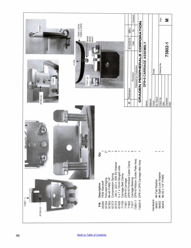
46 Back to Table of Contents
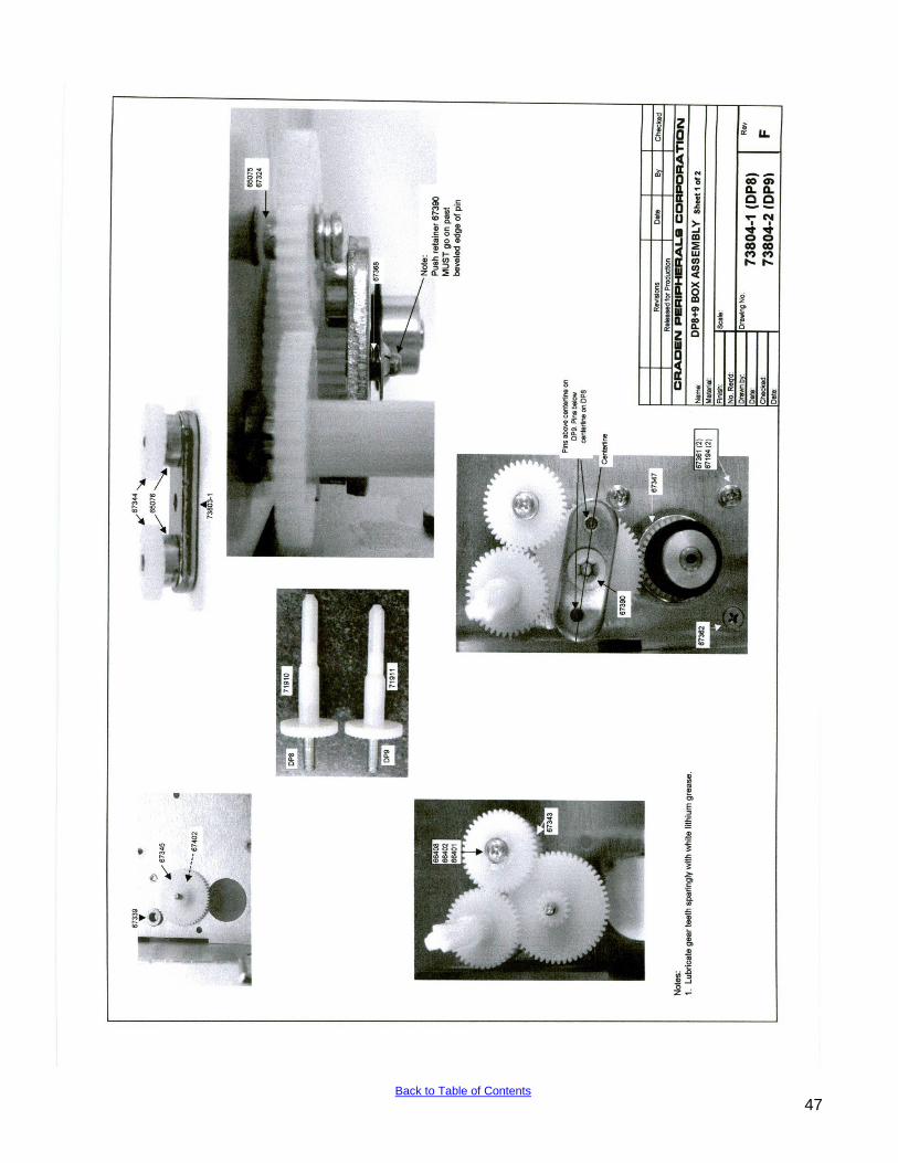
47 Back to Table of Contents
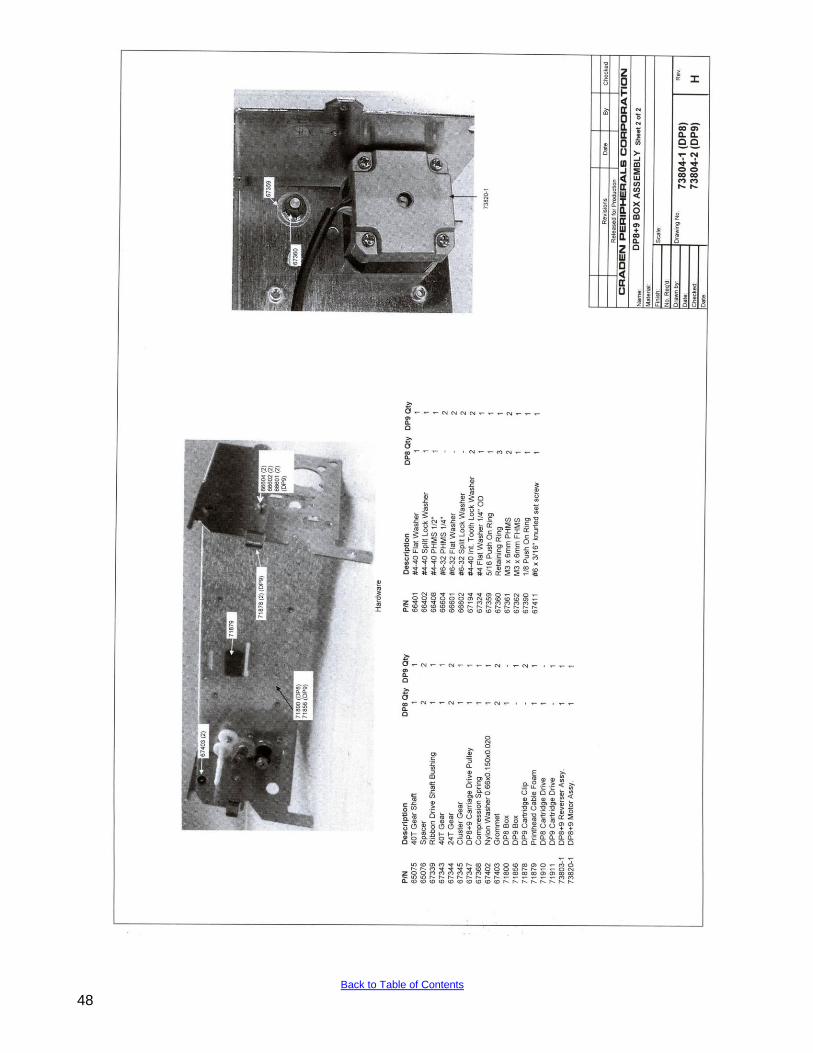
48 Back to Table of Contents
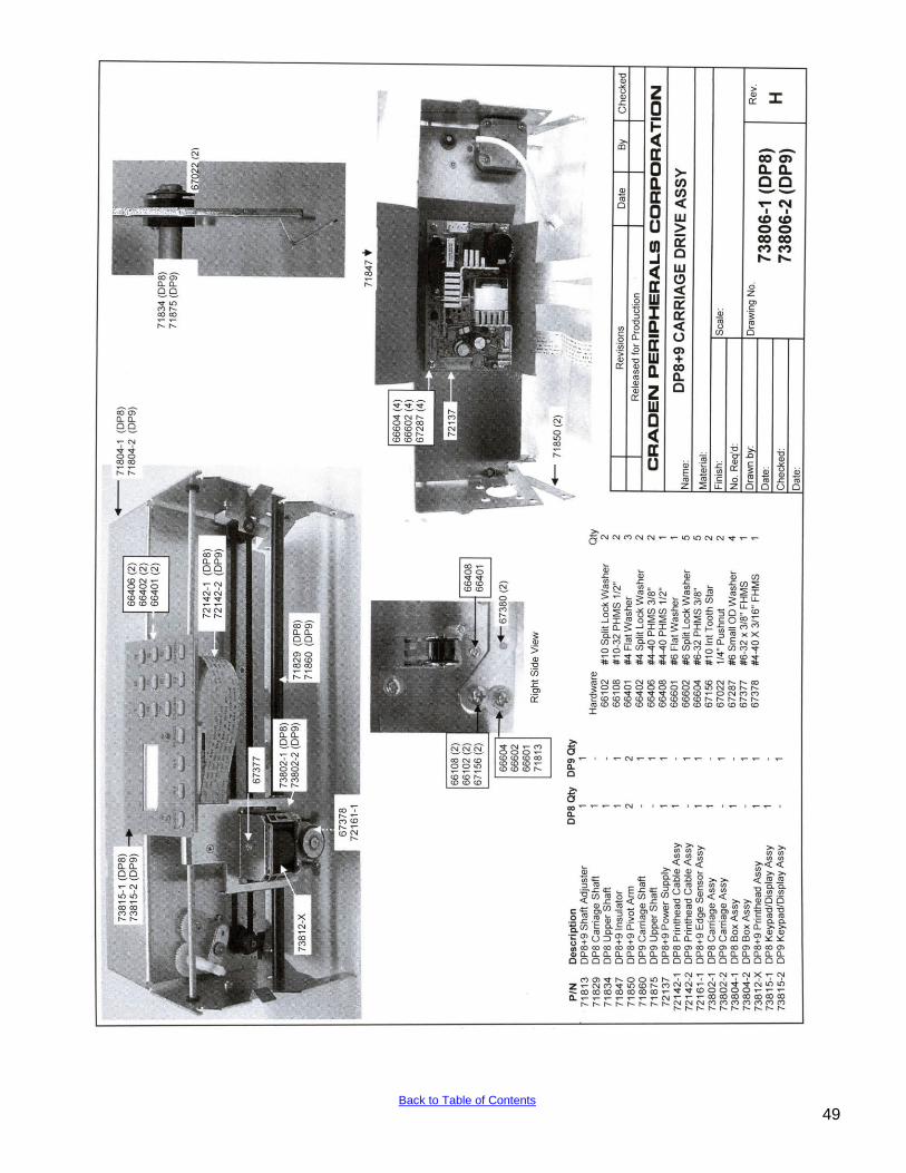
49 Back to Table of Contents
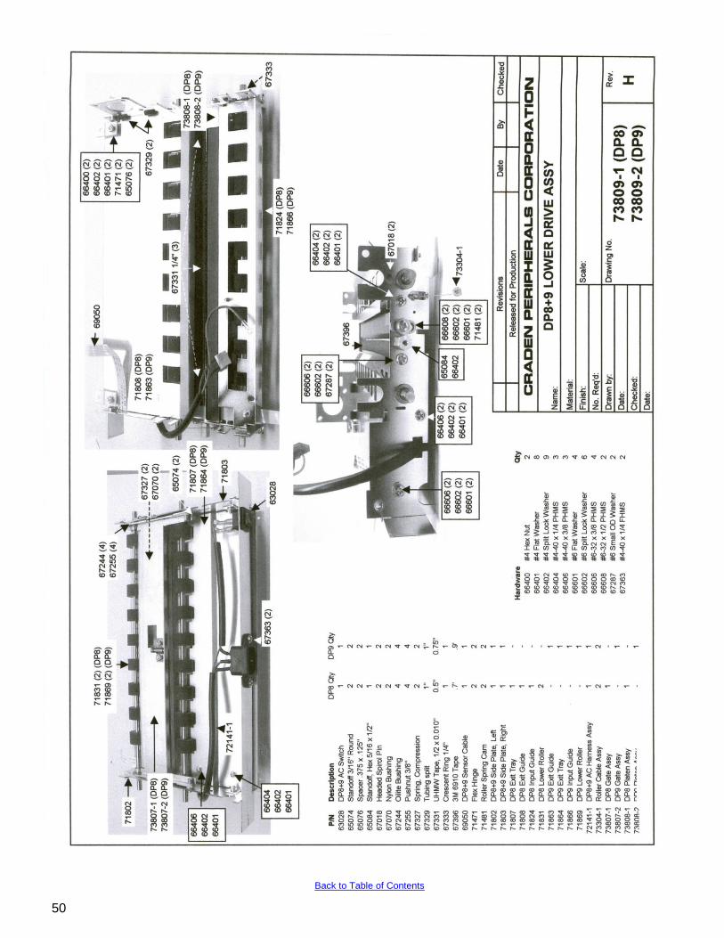
50
Back to Table of Contents
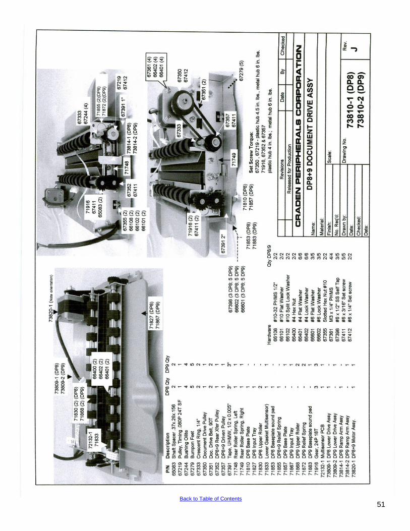
51 Back to Table of Contents
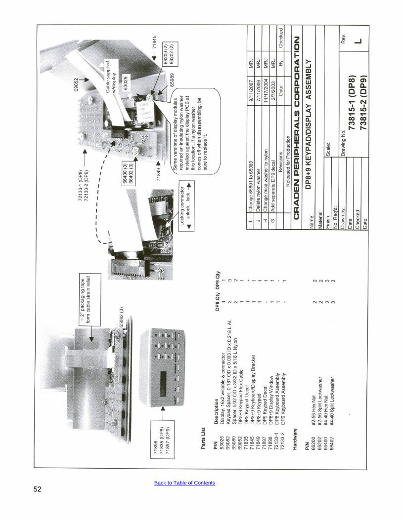
52 Back to Table of Contents
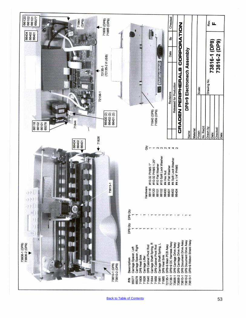
53 Back to Table of Contents
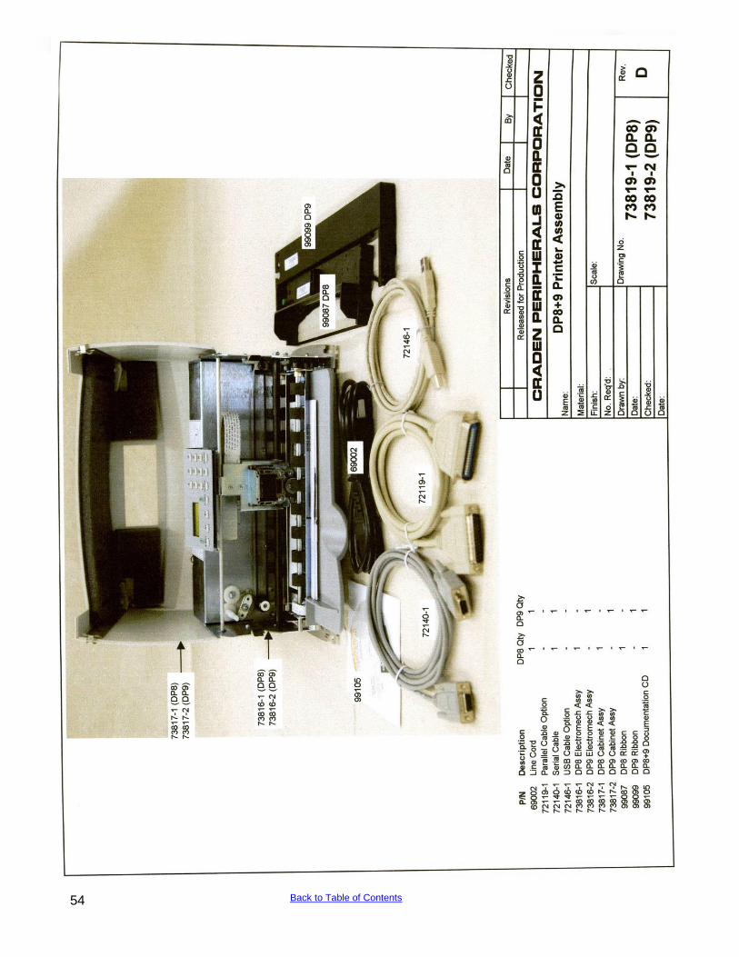
54 Back to Table of Contents