Embed Size (px)
Citation preview
Amend Section 511 - Drilled Shafts to read as follows:
“SECTION 511 - DRILLED SHAFTS
511.01 Description. This section is for installing drilled shafts according to the contract. Drilled shafts include reinforced or unreinforced concrete with or without concrete bell footings.
511.02 Materials. Materials shall conform to the following:
(A) Portland Cement Concrete. Concrete shall conform to Section 601 - Structural Concrete except the concrete shall have minimum 28-day compressive strength f'C = 4500 pounds per square inch.
Proportion the concrete mix designs to get properties of high workability, compaction under self-weight, and resistance to segregation. The maximum nominal aggregate size shall be 0.75 inch. The slump range shall be 7.0 inches 1.0 inch for concrete poured into a water free borehole and 8.0 inches 1.0 inch for concrete placed under water or under drilling slurry. Slump for the concrete shall be a minimum of four inches after four hours from initial mixing.
The Engineer will not permit superplasticizers.
(B) Reinforcing Steel. Reinforcing steel shall conform to Section 602 - Reinforcing Steel.
511.03 Qualifications of Drilled Shaft Contractor. The Drilled Shaft Contractor shall conform to Subsection 102.01 - Prequalification of Bidders and below.
(A) Drilled shaft Experience. Because of the expertise required to successfully complete the drilled shafts according to the contract, a qualified Drilled Shaft contractor shall install the drill shaft. The Drilled shaft Contractor shall have installed at least three projects completed in the last three years on which the Contractor has installed a minimum of five drilled shafts of a diameter and length similar to those shown in the contract. The Drilled Shaft Contractor shall have supervisory personnel who participated in the construction of drilled shafts similar to the type proposed for a duration of at least three years within the last 10 years.
511.04 Preconstruction Requirements.
(A) Experience Information. The Drilled Shaft Contractor shall submit the following information to the Engineer within 30 days after
(Project No.)511-1a 11/02/04
12345678910111213141516171819202122232425262728293031323334353637383940414243444546
12
award of contract: The Drilled shaft Contractor shall submit the following information to the Engineer within 30 days after award contract.
(1) List of drill shaft projects completed in the past three years. The list of projects shall contain the names and phone numbers of owner’s representatives who can verify the Contractor’s participation on that project.
(2) Name and experience record of the drilled shaft superintendent in charge of drilled shaft operations for this project
(3) A signed statement that the Drilled Shaft Contractor has inspected both the project site and the subsurface information including soil or rock samples made available in the contract documents.
(B) Protection of Existing Structures. Prevent damage to existing structures and utilities. Preventive measures shall include:
(1) Selecting construction methods and procedures that will prevent caving of the shaft excavation and
(2) Monitoring and controlling the vibrations from construction activities such as the driving of casing or sheeting or drilling of the shaft
(C) Installation Plan. At least one month before constructing the drilled shafts, submit an installation plan for acceptance by the Engineer. This plan shall provide information on the following:
(1) List of proposed equipment such as cranes, drills, augers, bailing buckets, final cleaning equipment, tremies or concrete pumps, and casing,
(2) Details of construction operation sequence and the sequence of shaft construction in bents or groups,
(3) Details of shaft excavation methods,
(4) When the contract requires slurry, details of the methods to mix, circulate and desand slurry,
(5) Details of methods to clean the shaft excavation,
(6) Details of reinforcement placement including support and centralization methods,
(Project No.)511-2a 11/02/04
474849505152535455565758596061626364656667686970717273747576777879808182838485868788899091929334
(7) Details of concrete placement including proposed operational procedures for free fall, tremie, or pumping methods, and
(8) Details of required load tests including equipment and procedures, and recent calibrations for jacks or load cells supplied by the Contractor.
The Engineer will evaluate the drilled shaft installation plan for conformance with the contract within 14 days after receipt of the plan, the Engineer will notify the Contractor of additional information required and/or changes necessary to meet the contract requirements. The Engineer will reject parts of the plan that are unacceptable. The Contractor shall resubmit changes for re-evaluation. Procedural acceptance given by the Engineer shall be subject to trial in the field. The acceptance shall not relieve the Contractor of the responsibility to complete the work according to the contract.
(D) Trial Shaft Installation. Show the adequacy of its methods and equipment by successfully constructing an unreinforced test shaft. Position this trial shaft away from production shafts in the location shown in the contract or as specified by the Engineer. Drill the trial shaft to the maximum depth shown in the contract. When shown in the contract, do the reaming of bells at specified trial shaft holes to establish the feasibility of belling in a specific soil strata.
Failure to show the Engineer the adequacy of methods and equipment shall be reason for the Engineer to require alterations in equipment and/or method by the Contractor. Additional trial holes required to show the adequacy of altered methods of construction or equipment shall be at no cost to the State. Once the Engineer has given acceptance to construct production shafts, the Engineer will not permit changes in the methods or equipment used to construct the satisfactory test shaft without consent of the Engineer.
Fill the trial shaft holes with unreinforced concrete similar to the construction of production shafts. Cut the concreted trial shafts off 610 millimeters below finished grade and leave in place. Restore the disturbed areas at the sites of the trial shaft holes to their original condition.
511.05 Construction Requirement.
(A) Construction Sequence. Complete the excavation to footing elevations before shaft construction begins. Repair the disturbances caused by shaft installation to the footing area before pouring the footing.
(Project No.)511-3a 11/02/04
949596979899100101102103104105106107108109110111112113114115116117118119120121122123124125126127128129130131132133134135136137138139140141
56
When installing drilled shafts with embankment placement, construct drilled shafts after the placement of fills.
Do not cap the drilled shafts before placing the fills as near to final grade as possible. Only leave room for construction of the caps.
(B) Construction Methods. Excavate for shafts and bell footings to the dimensions and elevations shown in the contract. Its methods and equipment shall be suitable for the intended purpose and materials met. Use the permanent casing method only when required by the contract or authorized by the Engineer
(1) Dry Construction Method. The dry method includes drilling the shaft excavation, removing accumulated water and loose material from the excavation, and placing the shaft concrete in a dry excavation. Use this method only at sites where the groundwater table and soil conditions are suitable to permit construction of the shaft in a dry excavation. The Engineer will inspect the sides and bottom of the shaft visually before placing the concrete
(2) Wet Construction Method. This method includes using water or mineral slurry to maintain stability of the hole perimeter while advancing the excavation to final depth, placing the reinforcing cage, and concreting the shaft. Use this method at sites where a dry excavation for placement of the shaft concrete cannot be maintained
When locating drilled shafts in open water areas, extend the exterior casings from above the water elevation into the ground. Install the exterior casing to produce a positive seal at the bottom of the casing so that no intrusion or extrusion of water or other materials occurs into or from the shaft excavation.
(3) Casing Construction Method. The casing method may be used when shown in the contract or at sites where the dry or wet construction methods are inadequate. The casing may be placed either in a predrilled hole or advanced through the ground by twisting, driving, or vibration before cleaning the casing.
(C) Excavation.
(1) General. Make the shaft excavations at locations, and to shaft geometry and dimensions shown in the contract. Lower drilled shaft tip elevations when the material met during excavation
(Project No.)511-4a 11/02/04
142143144145146147148149150151152153154155156157158159160161162163164165166167168169170171172173174175176177178179180181182183184185186187
78
is unsuitable and/or differs from that anticipated in the design of the drilled shaft.
Maintain a construction method log during shaft excavation. The log shall contain information such as:
(a) Excavation diameters,
(b) Type of material excavated with the elevations of the material
(c) Rate of excavation
(d) The description of and approximate top and bottom elevation of each soil or rock material
(e) Seepage or groundwater, and
(f) Remarks
On projects with cofferdams, provide a qualified diver to inspect the cofferdam conditions when the contract requires a seal for construction. Before placing the concrete seal, the diver shall inspect the cofferdam interior periphery. The cofferdam interior periphery inspection includes each sheeting indentation and around each drilled shaft.
Dispose the excavated material according to Section 203 - Excavation and Embankment.
When shown in the contract, excavate the bells to form the height and a bearing area of the size and shape specified in the contract. Excavate the bell mechanically.
Furnish drilled shaft concrete required to fill excavations for the bells and shafts dimensioned in the contract at no cost to the State.
Do not permit workers to enter the shaft excavation unless:
(a) A suitable casing is installed and the water level is lowered and stabilized and
(b) Adequate safety equipment and procedures are providers
(Project No.)511-5a 11/02/04
188189190191192193194195196197198199200201202203204205206207208209210211212213214215216217218219220221222223224225226227228229230231232233
910
(2) Excavation and Drilling Equipment. The excavation and drilling equipment shall have adequate capacity including power, torque, and down thrust to excavate a hole to the maximum diameter and to a depth of ten feet or 20% beyond the depths shown in the contract whichever is greater.
The excavation and overreaming tools shall be of adequate design, size, and strength to do the work shown in the contract.
(a) Special Drilling Equipment. When conventional earth augers and/or underreaming tools cannot be used for drilling, provide special drilling equipment including rock core barrels, rock tools, air tools, blasting materials and other equipment as necessary to construct the shaft excavation to the size and depth required. The Engineer will permit blasting only if stated in the contract or authorized in writing by the Engineer.
(b) Sidewall Overreaming. When the sidewall of the hole has softened, swelled, or degraded, sidewall overreaming is required. Overreaming thickness shall be a minimum of 0.5 inch and a maximum of 3.0 inches. The Contractor may overream with a grooving tool or overreaming bucket. The thickness and elevation of sidewall overreaming shall be according to the contract. Overream sidewall and place additional shaft concrete at no cost to the State.
(3) Classified Excavation. When designated in the contract, do the classified excavation under the standard and special excavation items. The Engineer will pay for obstruction removal separately.
(a) Standard Excavation. Standard excavation is excavation done with conventional tools. Conventional tools include augers fitted with soil or rock teeth, drilling buckets, and overreaming (belling buckets) attached to drilling equipment. This drilling equipment shall be of the size, power, torque, and down thrust (crowd) accepted for use by the Engineer after successful construction of a trial drilled shaft.
b) Special Excavation. Special excavation is excavation that requires special tools and/or procedures to advance the hole. The Engineer will pay for special excavation below the depth where conventional tools and drilling equipment accepted for standard excavation,
(Project No.)511-6a 11/02/04
2342352362372382392402412422432442452462472482492502512522532542552562572582592602612622632642652662672682692702712722732742752762772782792801112
operating at maximum power, torque and down thrust, cannot advance the hole. Get the refusal rate using the standard excavation tools and equipment when hole advancement is less than one foot after 15 minutes of continuous drilling at full power.
The Engineer will consider special excavation, except obstructions removal, despite the density or character of materials met.
(4) Unclassified Excavation. When the contract designates drilled shaft excavation as unclassified, provide the necessary equipment to remove and dispose of materials met in forming the drilled shaft excavation. The Engineer will not make separate payment for excavation of materials of different densities and character or employment of special tools and procedures necessary to excavate. The Engineer will pay for obstruction removal separately.
(5) Obstructions Removal. Remove obstructions at drilled shafts locations when authorized by the Engineer Such obstructions shall include man-made materials such as old concrete foundations and natural materials such as boulders
Drilling tools, lost in excavation, are considered obstructions. Remove the drilling tools promptly. The cost due to tools lost in the excavation shall be at no cost to the State including costs associated with hole degradation due to removal operations or the time the hole remains open.
(6) Coring Samples (Shaft Excavation). Take soil samples or rock cores when shown in the contract or as specified by the Engineer. Extract the soil samples with a split or undisturbed sample tube. Cut the rock cores with an acceptable double or triple tube core barrel.
Cut to a minimum of 10 feet below the bottom of the drilled shaft excavation at the time the shaft excavation is about complete. When required by the Engineer, extend the depth of the coring up to a total depth of 20 feet. Measure the rock core and standard penetration test samples, identify visually, and describe on its log. Place the samples in suitable containers, identify by shaft location, elevation, and project number. Deliver the samples with its field log to the Engineer within 24 hours after completing the exploration.
(Project No.)511-7a 11/02/04
281282283284285286287288289290291292293294295296297298299300301302303304305306307308309310311312313314315316317318319320321322323324325326
1314
The Engineer will inspect the samples or cores and decide the final depth of required excavation based on the Engineer's evaluation of the materials suitability. Furnish two copies of the typed final Contractor's log to the Engineer when the shaft excavation is accepted.
(D) Casings.
(1) General. Casings shall be steel, smooth, watertight, and of ample strength to withstand both handling and driving stresses and the pressure of concrete and the surrounding earth materials. The inside diameter of the casing shall not be less than the specified size of the shaft. The Engineer will not allow extra compensation for concrete required to fill the oversized casing or oversized excavation. Remove casings from shaft excavations except when the casing is permanent. The length of permanent casings installed below the shaft cutoff elevation, shall remain in place.
When the shaft extends above ground or through a body of water, the shaft may be formed with removable casing except when the casing is permanent For permanent casings, remove the portion of metal casings between an elevation two feet below the lowest water elevation and the top of shaft elevation after curing the concrete. Remove the casing carefully so that the casing will not damage the concrete. When the casings needs to be removed after the concrete hardens in open water, design and submit the special system for acceptance by the engineer. The Contractor may remove the casings when the concrete attains sufficient strength provided the:
(a) Curing of the concrete continues for the full 72 hours period.
(b) Shaft concrete is not exposed to salt water or moving water for 7 days and
(c) Concrete reaches a compressive strength of at least 2,500 pounds per square inch.
(2) Temporary Casing. The Engineer will consider subsurface casing temporary unless shown in the contract as permanent casing. Remove the temporary casing before completing the placing of concrete in the drilled shaft. The Contractor may require telescoping, predrilling with slurry, and/or overreaming to beyond the outside diameter of the casing to install casing.
(Project No.)511-8a 11/02/04
3273283293303313323333343353363373383393403413423433443453463473483493503513523533543553563573583593603613623633643653663673683693703713723731516
When choosing to remove a casing and substituting a longer or larger diameter casing through caving soils, stabilize the excavation with slurry or backfill before installing the new casing.
Before withdrawing the casing, the level of fresh concrete in the casing shall be the higher of the following:
(a) A minimum of five feet above the hydrostatic water level or
(b) The level of drilling fluid.
While withdrawing the casing, maintain an adequate level of concrete within the casing to:
(a) Displace the fluid trapped behind the casing upward and
(b) Discharge the fluid at the ground surface without contaminating or displacing the shaft concrete.
When temporary casings become bound or fouled during shaft construction and cannot be removed, the Engineer will consider the drill shaft defective. Improve such defective shafts according to the contract. Such improvement may consist of removing the shaft concrete and extending the shaft deeper providing the shaft is straddled or replaced. Do corrective measures including redesign of footings caused by defective shafts in accordance with the contract documents at no increase in contract price or contract time. The Engineer will not pay for the casing remaining in place.
(3) Permanent Casing. Use permanent casing when specified in the contract. The casing shall be continuous between top and bottom elevations according to the contract. After completing the installation, cut off the permanent casing at the prescribed elevation. Complete the shaft by installing necessary reinforcing steel and concrete in the casing.
When special temporary casings are in the contract or specified in writing by the Engineer, maintain the alignment of the temporary outer casing with the permanent inner casing and a positive, watertight seal between the two casings during excavation and concreting operations.
(E) Slurry. Use only mineral slurries in the drilling process. The slurry shall have a mineral grain size that will remain in suspension and
(Project No.)511-9a 11/02/04
3743753763773783793803813823833843853863873883893903913923933943953963973983994004014024034044054064074084094104114124134144154164174184194204211718
sufficient viscosity and gel characteristics to transport excavated material to suitable screening system. The percentage and specific gravity shall be sufficient to maintain the stability of the excavation and to allow proper concrete placement.
During construction, maintain the level of the slurry at a height sufficient to prevent caving of the hole. When a sudden significant loss of slurry occurs, delay the construction of that foundation until the Engineer submits an alternate construction procedure for acceptance by the Engineer.
Premix the mineral slurry thoroughly with clean fresh water and adequate time (as prescribed by the mineral manufacturer) allotted for dehydration before introducing mineral slurry into the shaft excavation. The slurry tanks shall have capacity for adequate slurry circulation, storage, and treatment. Excavated slurry pits in lieu of slurry tanks will not be allowed without the written permission of the Engineer.
Use desanding equipment to control slurry sand content to less than 4 percent by volume in the borehole. The Engineer will not require desanding equipment for setting temporary casing, sign post, or lighting mast foundations.
Prevent the slurry from "setting up" in the shaft, such as: agitation, circulation and/or adjusting the properties of the slurry. Dispose of slurry in suitable areas off from the project site.
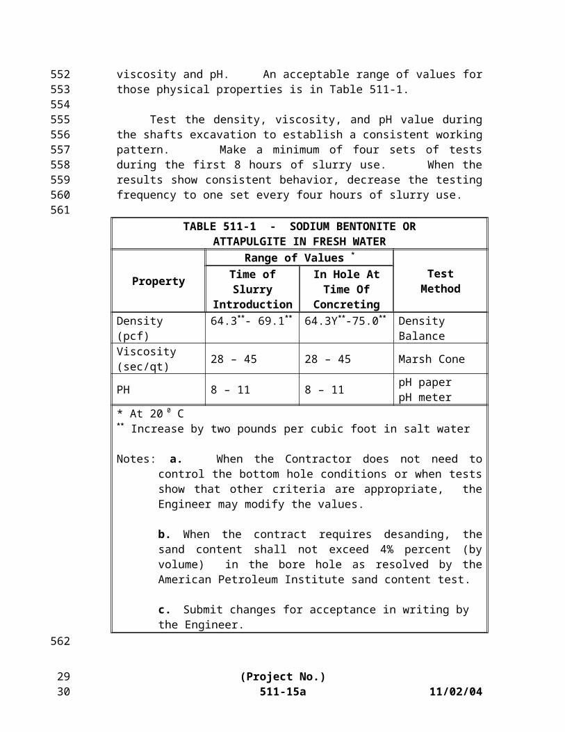
Carry out the control tests using suitable apparatus on the mineral slurry to resolve the density, viscosity and pH. An acceptable range of values for those physical properties is in Table 511-1.
Test the density, viscosity, and pH value during the shafts excavation to establish a consistent working pattern. Make a minimum of four sets of tests during the first 8 hours of slurry use. When the results show consistent behavior, decrease the testing frequency to one set every four hours of slurry use.
TABLE 511-1 - SODIUM BENTONITE ORATTAPULGITE IN FRESH WATER
PropertyRange of Values *
TestMethodTime of Slurry
IntroductionIn Hole At Time Of Concreting
Density (pcf) 64.3**- 69.1** 64.3Y**-75.0** Density BalanceViscosity(sec/qt) 28 – 45 28 – 45 Marsh Cone
(Project No.)511-10a 11/02/04
422423424425426427428429430431432433434435436437438439440441442443444445446447448449450451452453454455456457458
1920
PH 8 – 11 8 – 11 pH paperpH meter
* At 20 0 C ** Increase by two pounds per cubic foot in salt water
Notes: a. When the Contractor does not need to control the bottom hole conditions or when tests show that other criteria are appropriate, the Engineer may modify the values.
b. When the contract requires desanding, the sand content shall not exceed 4% percent (by volume) in the bore hole as resolved by the American Petroleum Institute sand content test.
c. Submit changes for acceptance in writing by the Engineer.
Before placing concrete in the shaft excavation, take slurry samples from the base of the shaft using a sampling tool. Extract slurry samples from the base of the shaft and at intervals not exceeding three meters up the shaft. Extract samples until two consecutive samples produce acceptable values for density, viscosity, pH, and sand content.
Ensure that the bottom of the shaft does not accumulate heavily contaminated slurry suspension. The heavily contaminated slurry suspension could impair the free flow of concrete. When finding unacceptable slurry samples, take actions necessary to bring the mineral slurry as specified in the contract. Do not pour the concrete until resampling and testing results produce acceptable values.
Furnish the reports of tests required above to the Engineer on completion of each drilled shaft. An authorized person of the Contractor shall sign the reports.
During construction, maintain at the level of mineral slurry not less than four feet above the highest piezometric water pressure along the depth of a shaft. When the slurry construction method fails, stop this method and propose an alternate method for acceptance by the Engineer
(F) Excavation Inspection. Provide equipment for checking the dimensions and alignment of each permanent shaft excavation. Determine the dimensions and alignment according to the contract. Measure the final shaft depths with a suitable weighted tape after final cleaning.
A minimum of 50% of the base of each shaft shall have less than 0.5 inch of sediment at the time the concrete is placed. The maximum depth of sediment or debris on the base of the shaft shall not exceed 1.5
(Project No.)511-11a 11/02/04
459460461462463464465466467468469470471472473474475476477478479480481482483484485486487488489490
2122
inches. The Engineer will decide the shaft cleanliness by visual inspection for dry shafts or other methods deemed appropriate to the Engineer for wet shafts.
Also, for dry excavations the maximum depth of water shall not exceed three inches before pouring the concrete.
(G) Reinforcing Steel Cage Construction and Placement. Assemble and place the reinforcing steel cage immediately after the Engineer inspects and accepts the shaft excavation before pouring the concrete The reinforcing steel cage includes longitudinal bars, ties, cage stiffener bars, spacers, centralizers, and other necessary appurtenances to complete the cage.
Tie and support the reinforcing steel in the shaft so that the reinforcing steel will remain within allowable tolerances given in Subsection 511.04(I). Use the concrete spaces at sufficient intervals (near the bottom and at intervals not exceeding 10 feet up the shaft) to insure concentric spacing for the entire cage length. Construct the spacers of accepted material equal in quality and durability to the concrete specified for the shaft. The spacers shall be of adequate dimension to insure a minimum of three inches annular space between the outer portion of the reinforcing cage and the side of the excavated hole. Provide accepted cylindrical concrete bottom supports to maintain the proper distance between bottom of the cage and base of the shaft excavation.
Check the elevation of the top of the steel cage before and after pouring the concrete. When not maintaining the rebar within the specified tolerances, make the corrections according to the contract. Do not construct additional shafts until after modifying the rebar cage support according to the contract.
When the bottom of the constructed shaft elevation is lower than shown in the contract, extend at least half of the longitudinal bars required in the upper portion of the shaft the additional length. Continue the tie bars for the extra depth, spaced two-foot on center. Extend the stiffener bars to the final depth. These bars may be lap splice or unspliced bars of the proper length. The Engineer will not permit welding to the reinforcing steel.
(H) Concrete Placement.
(1) General. Place the concrete through a tremie, concrete pump or by drop chute using accepted methods as described below.
(Project No.)511-12a 11/02/04
4914924934944954964974984995005015025035045055065075085095105115125135145155165175185195205215225235245255265275285295305315325335345355365372324
If possible, place the concrete immediately after placing the reinforcing steel
Concrete placement shall be continuous from the bottom to the top elevation of the shaft. Concrete placement shall continue after the shaft is full until good quality concrete is evident at the top of shaft.
The elapsed time from the beginning of concrete placement in the shaft to the completion of the placement shall not exceed two hours. Adjust the accepted admixtures on the job site so that concrete remains in a workable plastic state throughout the hour placement limit. A longer placement time may be requested
Before placing the concrete, provide test results of a trial mix and a slump loss test. An accepted testing laboratory shall conduct the test using accepted methods. Supply a concrete mix that will maintain a slump of four inches or greater. Conduct temperatures appropriate for site conditions.
(2) Concreting by Tremie. Tremies may be used for concrete placement in wet or dry excavations Tremies shall include a tube of sufficient length, weight, and diameter to discharge concrete at the shaft base elevation. The tremie shall not contain aluminum parts that will have contact with the concrete. The tremie inside diameter shall be at least 6 times the maximum size of aggregate used in the concrete mix but shall not be less than 10 inches. The inside and outside surfaces of the tremie shall be clean and smooth to permit flow of concrete and unimpeded withdrawal during concreting. The wall thickness of the tremie shall be adequate to prevent crimping or sharp bends that restrict concrete placement.
The tremie used for wet excavation concrete placement shall be watertight. Underwater placement shall not begin until after placing the tremie to the shaft base elevation. Valves, bottom plates or plugs may be used only if concrete discharge begins within one tremie diameter of the base.
Remove the plugs from the excavation. When not removing the plugs, an acceptable material will remain that will not cause a defect in the shaft
Construct the discharge end of the tremie to permit the free radial flow of concrete during placement operations. Immerse the tremie discharge end at least
(Project No.)511-13a 11/02/04
5385395405415425435445455465475485495505515525535545555565575585595605615625635645655665675685695705715725735745755765775785795805815825835842526
5feet in concrete after starting the flow of concrete. The flow of concrete shall be continuous. Maintain the concrete in the tremie at a positive pressure differential to prevent water or slurry intrusion into the shaft concrete.
When removing the tremie line orifice from the fluid concrete column and discharging concrete above the rising concrete level during the concrete pour, the Engineer will consider the shaft defective. In such case, remove the reinforcing cage and concrete, the necessary sidewall removal specified by the Engineer, and repour the shaft. Costs of replacement of defective shafts shall be at no costs to the State.
(3) Concreting by Pump. Concrete pumps and lines for concrete placement in wet or dry excavations may be used. Pumps and pump lines used to place concrete shall be of sufficient length, weight, and diameter to discharge concrete at the shaft base elevation. The pump and pump lines that are in the contact with concrete shall not contain aluminum parts. Pump lines shall have a minimum diameter of four inches and watertight joints. Concrete placement shall not begin until the pump line discharge orifice is at the shaft base elevation.
For wet excavations, use a plug to separate the concrete from the fluid in the hole until pumping begins. Remove the plug from the excavation. When the plug is not removed, leave a material accepted by the Engineer that will not cause a detect
The discharge orifice shall remain at least five feet below the surface of the fluid concrete. When lifting the pump line during concreting, reduce the line pressure temporarily until the orifice at a higher level in the excavation has been repositioned.
When removing the pumpline orifice from the fluid concrete column and discharging concrete above the rising concrete level during the concrete pour, the Engineer will consider the shaft defective. In such case, remove the reinforcing cage and concrete, the necessary sidewall removal specified by the Engineer, and repour the shaft. Costs of replacement of defective shafts shall be at no costs to the State.
(4) Concreting by Drop Chutes. The Engineer will permit free fall placement of concrete only in dry excavations. Dry excavations are excavations where the maximum depth of water does not exceed three inches. The Engineer will not permit free fall method in wet excavations.
(Project No.)511-14a 11/02/04
5855865875885895905915925935945955965975985996006016026036046056066076086096106116126136146156166176186196206216226236246256266276286296306312728
Use the drop chutes to direct placement of free fall concrete. Drop chutes shall include a smooth tube of one piece construction or sections that the Contractor may add or remove. The concrete may be placed through a hopper at the top of the tube or side openings during concrete placement. Support the drop chute so that the free fall of the concrete measured from the bottom of the chute is less than 25 feet.
Concrete placed by free fall shall fall directly to the base without contacting the rebar cage or hole sidewall. When concrete placement causes the shaft excavation to cave or slough, or when the concrete strikes the rebar cage or sidewall, reduce the height of free fall or reduce the rate of concrete flow into the excavation. When the concrete cannot be placed satisfactorily by free fall, use tremie or concrete pump to pour.
(I) Construction Tolerances. The following construction tolerances apply to drilled shafts:
(1) The drilled shaft shall be within 1/12 of the shaft diameter or three inches, whichever is less, in the horizontal plane at the plan elevation for the top of the shaft.
(2) The vertical alignment of the shaft excavation shall not vary from the plan alignment by more than 0.25 inch per foot of depth. The alignment of a battered shaft excavation shall not vary by more than 0.5 inch per foot of depth from the prescribed batter.
(3) After placing the concrete, the top of the reinforcing steel cage shall be no more than 6.0 inches above and no more than 3.0 inches below plan position.
(4) Casing diameters shown in the contract refer to outside diameter (OD) dimensions. When accepted by Engineer, a casing larger in diameter than shown in the contract may be provided to ease meeting this requirement. When not using casing, the minimum diameter of the drilled shaft shall be one inch less than the specified shaft diameter. When using a series of telescoping casings, size the casing so that the minimum shaft diameters listed above can be maintained.
(5) Excavate the bearing area of bells to the plan bearing area as a minimum. The diameter of the bells shall not exceed three times the specified shaft diameter. Other plan dimensions shown for the bells may vary when accepted by the Engineer.
(Project No.)511-15a 11/02/04
6326336346356366376386396406416426436446456466476486496506516526536546556566576586596606616626636646656666676686696706716726736746756766776782930
(6) The top elevation of the shaft shall have a tolerance of ± 1.0 inch from the plan top of shaft elevation.
(7) The dimensions of casing are subject to American Pipe Institute tolerances applicable to regular steel pipe.
(8) Design the excavation equipment and methods so that the completed shaft excavation will have a flat bottom. The cutting edges of excavation equipment shall be normal to the vertical axis of the equipment within a tolerance of ± 3/8 inch per foot of diameter.
Drilled shaft excavations that cannot be completed within the required tolerances are unacceptable. When accepted by the Engineer, corrections may be made to an unacceptable drilled shaft excavation by accepted combination of the following methods:
(1) Overdrill the shaft excavation to a larger diameter to permit accurate placement of the reinforcing steel cage with the required minimum concrete cover.
(2) Increase the number or size of the reinforcing steel.
(3) Enlarge the bearing area of the bell excavation within the tolerances allowed.
The acceptance of correction procedures is dependent on analysis of the effect of the degree of misalignment and improper positioning. The Engineer may accept the correction methods as design analysis. A Hawaii Licensed Professional Engineer shall sign the redesign drawings and computations. Correct out of tolerance drilled shaft excavations including engineering analysis and redesign at no cost to the State.
(J) Drilled Shaft Load Tests. The use of load tests, the number of load tests and locations shall be shown in the contract or as specified by the Engineer. When specified in the contract, complete static, load tests before constructing production drilled shafts. Allow 7 working days after completing the last load test before the Engineer provides estimated drilled shaft tip elevations for production shafts.
Obtain the services of a Hawaii Licensed Professional Engineer with satisfactory load test experience:
(1) To conduct the test according to the contract,(Project No.)
511-16a 11/02/04
6796806816826836846856866876886896906916926936946956966976986997007017027037047057067077087097107117127137147157167177187197207217227237247253132
(2) Record data, and
(3) Furnish reports of the test results to the Engineer.
Load the load test shaft to a maximum test load equal to three times the design service load, or to plunging failure, whichever occurs first. Plunging failure is a deflection of the shaft head equal to 5% of the shaft diameter.
Do not begin static load testing until attaining a compressive strength of 3,000 pounds per square inch. Load-test the drilled shafts in the order specified by the Engineer. Complete the static load tests as described in ASTM D 1143 (Compression Test) quick test method and ASTM D 3966 (Lateral Test) or as modified herein. Supply equipment necessary to conduct the static test. Design the loading frame apparatus to ease the maximum load plus an adequate safety factor.
Notify the Engineer within 10 calendar days of contract award of the load testing schedule.
The Engineer will require load cells for drilled shaft load tests. Load cells shall be of adequate size to measure the maximum load to the applied shaft. Equip the load cell with an adequate readout device. Before load testing begins, furnish a certificate from an accepted testing laboratory showing the calibration for the load cell within the preceding 6 months for stages of loading and unloading. The accuracy of the load cell shall be within 1% of the true load.
After completing the test, cut off the test shafts and reaction shafts at an elevation two feet below the finished ground surface. The portion of the shafts cut off and removed shall remain the property of the Contractor.
511.06 511.06 Method of Measurement.
(1) The Engineer will not measure furnishing Furnishing drilled shaft drilling equipment; and furnishing instrumentation instrumental and collecting data will be paid on a lump sum basis.for payment.
(2) The Engineer will measure obstructions per hour in accordance with the contract documents. Once the Engineer authorizes compensation for obstruction removal, duration of obstruction removal, including time required for obstruction disposal, will be measured for payment. Depth of obstruction removed will be subtracted from total depth measured for payment under other applicable drilled shaft excavation pay items. The Engineer will not include the length of time required to remove under this item in the quantities of other excavations
(Project No.)511-17a 11/02/04
726727728729730731732733734735736737738739740741742743744745746747748749750751752753754755756757758759760761762763764765766767768769770771772773
3334
items. The Engineer will subtract them from the total depth of the applicable excavation item.
(3) The Engineer will measure the load test per each in accordance with the contract documents..
The Engineer will measure the following per linear foot complete in place:
(14) The Engineer will measure Drilled drilled Shaftsshafts per linear foot. The Engineer will compute length shall be the difference shall be the difference between the plan top shaft elevation and the final bottom of shaft elevation.
(25) The Engineer will measure Standard standard Excavationexcavation per linear foot, . The Engineer will measure the standard excavation along the shaft centerline of the shaft including bells.
(36) The Engineer will measure Special special Excavation excavation per linear foot, The Engineer will measure the special excavation along the shaft centerline, of the shaft including bells, from refusal the elevation authorized by the Engineer to accepted shaft bottom elevation.
(47) The Engineer will measure Unclassified unclassified Shaft shaft Excavationexcavation per linear foot, . The Engineer will not measure the unclassified shaft excavation along the centerline of the shaft including bells. The Engineer will measure the unclassified shaft excavation along the shaft centerline of the shaft including bells. The Engineer will compute measure the length from the difference between the plan top of shaft elevation to the plan estimated tip elevation.
(58) The Engineer will measure unclassified extra depth excavation per linear foot, Unclassified Extra Depth Excavation per linear foot. The Engineer will compute measure length between plan from shaft estimated shaft tip elevation and shown in the contract to the final authorized and accepted shaft bottom of shaft elevation.
(69) The Engineer will measure drilled shaft sidewall overreaming Drilled Shaft Sidewall Overreaming. per linear foot, The Engineer will measure the drilled sidewall overreaming between the plan elevation limits shown in the contract or as authorized by the Engineer.
(710) The Engineer will measure trial shaft holesTrial Shaft Holes. per linear foot. The Engineer will measure compute length the difference between the existing ground surface elevation at the trial shaft hole center, of the test shaft hole before drilling, and authorized bottom elevation of the hole, including bells.
(Project No.)511-18a 11/02/04
7747757767777787797807817827837847857867877887897907917927937947957967977987998008018028038048058068078088098108118128138148158168178188198203536
(811) The Engineer will measure coring samples (Shaft Excavation)Coring Samples (Shaft Excavation). per linear foot. The Engineer will compute not measure length between from the bottom of shaft elevation aned to the bottom of the exploration hole, for each authorized exploration drilled below the shaft excavation.
(912) The Engineer will measure permanent casingPermanent Casings per linear foot. The Engineer will compute measure length between along the casing from the top of the shaft elevation or the top of casing, whichever is lower, and to the bottom of the casing, at each shaft location where using permanent casing is used.
511.07 511.07 Basis of Payment. The Engineer will pay for the accepted pay items listed below at the contract price per pay unit, as shown in the proposal schedule. Payment will be full compensation for the work prescribed in this section and the contract documents.
The Engineer will pay for furnishing drilled shaft drilling equipment at the contract lump sum price. The price includes full compensation for furnishing and moving the drilling equipment to the project; setting the equipment up at the locations; removing the equipment from the project; and furnishing labors, materials, tools, and incidentals necessary to complete the work. The Engineer will pay for 60 percent of the amount bid for this item when the drilling equipment is on the job site, assembled, and ready to drill foundation shafts. The Engineer will pay for the remaining 40 percent of the amount bid when the Contractor has drilled the shafts, and the Contractor has placed the shaft concrete up to the top of the shafts.
The Engineer will pay for furnishing instrumentation and collecting data at the contract lump sum price. The price includes full compensation for furnishing instrumentation; collecting data; reporting load test when required; and furnishing labor, materials, tools, and incidentals necessary to complete the work.
The Engineer will pay for the accepted removal of obstructions at the contract unit price per hour. The maximum payment per designated obstruction shall not exceed 20 times the unit cost for standard excavation or unclassified excavation whichever is less. The price includes full compensation for removing the obstruction; disposing the obstruction; and furnishing labor, materials, tools, equipment, and incidentals necessary to complete the work.
The Engineer will pay for the accepted load tests at the contract unit price per each complete in place. The price includes full compensation for load tests, costs related to the performance of the load test, furnishing labor, materials, tools, equipment, and incidentals necessary to complete the work.
(Project No.)511-19a 11/02/04
8218228238248258268278288298308318328338348358368378388398408418428438448458468478488498508518528538548558568578588598608618628638648658668673738
The Engineer will pay for the accepted drilled shafts at the contract unit price per linear foot for drilled shaft of the diameter specified. The price includes full compensation for furnishing and installing concrete and reinforcing steel, furnishing labor, materials, equipment, tools, and incidentals necessary to complete the drilled shaft.
The Engineer will pay for the accepted standard excavation at the contract unit price per linear foot for drilled shafts of the diameter specified. The price includes full compensation for furnishing labor, materials, equipment, tools, and incidentals necessary to complete the drilled shaft.
The Engineer will pay for the accepted special excavation at the contract unit price per linear foot for drilled shafts of the diameter specified. The price includes full compensation for furnishing labor, materials, equipment, tools, and incidentals necessary to complete the drilled shaft.
The Engineer will pay for the accepted unclassified shaft excavation at the contract unit price per linear foot for drilled shafts of the diameter specified. The price includes full compensation for furnishing and installing the temporary casing, removing and disposing of excavated materials, using slurry as necessary, using drilling equipment, blasting, using special tools and drilling equipment to excavate the shaft to the depth shown in the contract, and furnishing labor, materials, equipment, tools and incidentals necessary to complete the work.
The Engineer will pay for the accepted unclassified extra depth excavation at 150 percent of the contract unit price per linear foot of the diameter specified. The price includes full compensation for the costs of excavating below the bottom of shaft elevations shown in the contract except the additional costs included under the associated pay items for permanent casing. Work under this item is the same as that described under unclassified shaft excavation and additional work of excavating below the plan bottom of shaft elevation. The Engineer will pay for compensation under this item only when the Engineer authorizes the extra depth excavation.
The Engineer will pay for the accepted drilled shaft sidewall overreaming at the contract unit price per linear foot. The price includes full compensation for furnishing labor, materials, tools, equipment, and incidentals necessary to complete the work.
The Engineer will pay for the accepted trial shaft holes of the specified diameter at the contract unit price per linear foot. The price includes full compensation for excavating the trial shaft holes through to the bottom of shaft elevation shown in the contract or as authorized by the Engineer (using mineral slurry as necessary), providing inspection facilities, backfilling the hole, restoring the site as required, furnishing labor, materials, tools, equipment, and
(Project No.)511-20a 11/02/04
8688698708718728738748758768778788798808818828838848858868878888898908918928938948958968978988999009019029039049059069079089099109119129139143940
incidentals necessary to complete the work. The Engineer will not pay for trial shaft holes that the Contractor failed to show to the Engineer the adequacy of its proposed methods and equipment.
The Engineer will pay for the accepted coring sample (shaft excavation) at the contract unit price per linear foot. The price includes full compensation for taking soil samples, rock cores of the diameter and length required and authorized by the Engineer, drilling, extraction, packaging and classifying the samples or cores, delivering them to the Engineer, furnishing concrete to fill the core hole, furnishing labor, materials, tools, equipment, and incidentals necessary to complete the work.
The Engineer will pay for the accepted permanent casings at the contract unit price per linear foot. The price includes full compensation for furnishing, and placing the permanent casing in the shaft excavation, furnishing labor, materials, tools, equipment, and incidentals necessary to complete the work.
The Engineer will pay for each of the following pay items when included in the proposal schedule:make payment under:
Pay Item Pay Unit
Furnishing Drilled Shaft Drilling Equipment Lump Sum
The Engineer will pay for:
(1) 60 percent of the contract bid price when the drilling equipment is on the job site, assembled, and ready to drill foundation shafts.
(2) 40 percent of the contract bid price upon completion of drilling the shafts, and placing the shaft concrete up to the top of the shafts.
Furnishing Instrumentation and Collecting Data Lump Sum
Obstructions Hour
The Engineer will pay for:
(1) 80 percent of the contract bid price upon completion of removing the obstruction.
(2) 20 percent of the contract bid price upon completion of removing and disposing the obstruction
(Project No.)511-21a 11/02/04
915916917918919920921922923924925926927928929930931932933934935936937938939940941942943944945946947948949950951952953954955956957958959960
4142
The maximum payment per designated obstruction shall not exceed 20 times the unit cost for standard excavation or unclassified excavation whichever is less.
Load Test Each
The Engineer will pay for:
(1) 100 percent of the contract bid price upon completion of testing the load and other related costs to the performance of the load test.
Drilled Shaft Linear Foot
The Engineer will pay for:
(1) 60 percent of the contract bid price upon completion of drilling.
(2) 20 percent of the contract bid price upon completion of furnishing, assembling and placing the steel cage.
(3) 20 percent of the contract bid price upon completion of furnishing and placing the concrete.
(4) 10 percent of the contract bid price upon completion of removing and disposing the excavated material.
Standard Excavation Linear Foot
The Engineer will pay for:
(1) 80 percent of the contract bid price upon completion of excavating before drilling shaft by using conventional tools include augers fitted with soil or rock teeth, drilling buckets, and overreaming (belling buckets) attached to drilling equipment.
(2) 20 percent of the contract bid price upon completion of removing and disposing the excavated material.
Special Excavation Linear Foot
The Engineer will pay for:
(Project No.)511-22a 11/02/04
9619629639649659669679689699709719729739749759769779789799809819829839849859869879889899909919929939949959969979989991000100110021003100410051006
4344
(1) 80 percent of the contract bid price upon completion of excavating by using special tools or other acceptable procedures to advance the hole.
(2) 20 percent of the contract bid price upon completion of removing and disposing the excavated material.
Unclassified Shaft Excavation Linear Foot
The Engineer will pay for:
(1) 60 percent of the contract bid price upon completion of using slurry, using drilling equipment, blasting, using special tools and drilling equipment to excavate the shaft
(2) 20 percent of the contract bid price upon completion of furnishing and installing the temporary casing
(3) 20 percent of the contract bid price upon completion of removing and disposing the excavated material.
Unclassified Extra Depth Excavation Linear Foot
The Engineer will pay for:
(1) 80 percent of the contract bid price upon completion of excavating below the bottom of shaft elevations including permanent casing.
(2) 20 percent of the contract bid price upon completion of removing and disposing the excavated material.
Only when authorized by the Engineer, the Engineer will pay for the accepted unclassified extra depth excavation at 150 percent of the contract unit price per linear foot of the diameter specified.
Drilled Shaft Sidewall Overreaming Linear Foot
The Engineer will pay for:
(1) 80 percent of the contract bid price upon completion of overreaming the sidewall drilled shaft.
(2) 20 percent of the contract bid price upon completion of removing and disposing the excavated material.
(Project No.)511-23a 11/02/04
100710081009101010111012101310141015101610171018101910201021102210231024102510261027102810291030103110321033103410351036103710381039104010411042104310441045104610471048104910501051105210534546
Trial Shaft Holes Linear Foot
The Engineer will pay for:
(1) 60 percent of the contract bid price upon completion of excavating the trial shaft holes through to the bottom of shaft elevation or as authorized by the Engineer (using mineral slurry as necessary) and providing inspection facilities.
(2) 20 percent of the contract bid price upon completion of backfilling the hole.
(3) 20 percent of the contract bid price upon completion of restoring the site.
The Engineer will not pay for trial shaft holes that the Contractor failed to show to the Engineer the adequacy of its proposed methods and equipment.
Coring Samples (Shaft Excavation) Linear Foot
The Engineer will pay for:
(1) 70 percent of the contract bid price upon completion of soil sampling and rock coring.
(2) 20 percent of the contract bid price upon completion of filling the cored holes with non-shrink grout of the same minimum strength as drilled shaft.
(3) 10 percent of the contract bid price upon completion of packaging and classifying the samples or cores and delivering them to the Engineer
Permanent Casing Linear Foot
The Engineer will pay for:
(1) 100 percent of the contract bid price upon completion of furnishing and installing permanent casings.
(Project No.)511-24a 11/02/04
105410551056105710581059106010611062106310641065106610671068106910701071107210731074107510761077107810791080108110821083108410851086108710881089109010911092109310941095109610971098109911004748
END OF SECTION 511
(Project No.)511-25a 11/02/04
1101110211031104
4950