Embed Size (px)
Citation preview

© Baxi Heating U.K. Limited 2007.
5118782/02
Model 941INSET LIVE FUEL EFFECT GAS FIRE
Fitted with one of the following fascia.
Anthem, Blenheim, Bolero,Camden, Minima, Prelude, Seattle, Sonnet, Victorian or
Westminster fascia
(GC No. 32-811-21)
We trust that this guide givessufficient details to enable thisappliance to be installed andmaintained satisfactorily. However, iffurther information is required, ourBaxi Fires Division TechnicalHelpline will be pleased to help.Telephone 08706 061 065 (Nationalcall rates apply in the UnitedKingdom).In the Republic of IrelandTelephone 0044 8706 061 065.
THIS APPLIANCE IS FOR USE WITHNATURAL GAS (G20).
WHEN CONVERTED USINGCONVERSION KIT NO. 0595211 THIS
APPLIANCE IS FOR USE WITHPROPANE GAS (G31).
THIS APPLIANCE IS SUITABLE ONLYFOR INSTALLATION IN THE UNITEDKINGDOM (GB) AND THE REPUBLIC
OF IRELAND (IE).
INSTALLER: Please leave this guide with the owner
INSTALLER GUIDE

© Baxi Heating U.K. Limited 2007.All rights reserved. No part of this publication may be reproduced in any material form(including photocopying), stored in any medium by electronic means (including in any
retrieval system or database) or transmitted, in any form or by any means, whetherelectronic, mechanical, recording or otherwise, without the prior written permission of
the copyright owner.
Applications for the copyright owner's permission to reproduce any part of thispublication should be made, giving details of the proposed use, to the following address:The Company Secretary, Baxi Heating UK Limited, Pentagon House, Sir Frank Whittle
Road, Derby, DE21 4XA.
Warning: Any person who does any unauthorised act in relation to a copyright workmay be liable to criminal prosecution and civil claims for damages.
Baxi Fires Division, Erdington, Birmingham B24 9QPwww.firesandstoves.co.uk
Because our policy is one of constant development and improvement, details may vary slightly from thosegiven in this publication
Page 2
INSTALLER GUIDE
© Baxi Heating U.K. Limited 2007.

Page 3
INSTALLER GUIDESafety First.
Baxi Fires Division fires are CE Approved and designed to meet the appropriate BritishStandards and Safety Marks.
Quality and Excellence.All Baxi Fires Division fires are manufactured to the highest standards of quality andexcellence and are manufactured under a BS EN ISO 9001 quality system accepted by
the British Standards Institute.
The Highest StandardsBaxi Fires Division is a member of the Society of British Gas Industries which works to
ensure high standards of safety, quality and performance.
Careful InstallationBaxi Fires Division is a CORGI registered company. All our gas fires must be
installed by a competent CORGI Registered Installer in accordancewith our Installer Guide and should not be fitted directly on to a
carpet or floor of combustible material.
© Baxi Heating U.K. Limited 2007.

Page 4
INSTALLER GUIDE
© Baxi Heating U.K. Limited 2007.
CONTENTSSection Heading Page
1. SAFETY 52. APPLIANCE DATA 63. GENERAL INSTALLATION REQUIREMENTS 74. PACK CONTENTS 155. FIREPLACE CHECK 196. IGNITION CHECK 217. GAS SUPPLY CONNECTION 218. PREPARING APPLIANCE FOR INSTALLATION 229. HOTBOX INSTALLATION 24
9.1 Method 1 - Front fixing to fireplace surround. 249.2 Method 2 - Cable retention and floor fixing. 249.3 Sealing floor front 26
10. BURNER & SUPPLY PIPE INSTALLATION 2710.1 Burner and supply pipe installation. 2710.2 Preliminary burner checks. 2710.3 Inlet pressure check. 28
11. CERAMIC WALLS INSTALLATION 2812. FITTING THE FASCIA 2913. FITTING THE CERAMIC FUEL EFFECT 3114. FITTING THE FIREFRONT 3115. FULL OPERATING CHECKS 33
15.1 Check the control settings. 3315.2 Check for spillage. 3415.3 Flame supervision and spillage monitoring system. 34
16. FINAL REVIEW 3517. SERVICING & PARTS REPLACEMENT 36
17.1 Checking the aeration setting of the burner. 3717.2 To remove the Westminster and Bolero fascia. 3717.3 To remove the Victorian fascia. 3717.4 To remove the Anthem, Blenheim, Camden, Minima and Sonnet fascia. 3817.5 To remove the complete burner unit. 3817.6 To remove the pilot unit. 3817.7 To remove the gas valve. 3917.8 To remove the piezo generator. 3917.9 To grease the control tap. 3917.10 To replace the burner. 4017.11 To remove the main burner injector. 4017.12 To remove the appliance from the fireplace. 40

1. SAFETY
InstallerBefore continuing any further with the installation of this appliance please read thefollowing guide to manual handling:
! The lifting weight of this appliance is as below:
Model Heat Engine (kg) Fascia / Firefront (kg) Combined Weight (kg)Anthem 4.9 2.01 6.91Blenheim 4.9 3.86 8.76Bolero 4.9 13.35 18.25Camden 4.9 0.71 5.61Minima 4.9 1.16 6.06Prelude 4.9 3.75 8.74Seattle 4.9 0.71 5.61Sonnet 4.9 3.86 8.76Victorian 4.9 5.23 10.13Westminster 4.9 9.56 14.46
! One person should be sufficient to lift the fire. If for any reason this weight is considered too heavy then obtain assistance.
! When lifting always keep your back straight. Bend your legs and not your back.! Avoid twisting at the waist. It is better to reposition your feet.! Avoid upper body/top heavy bending. Do not lean forward or sideways whilst
handling the fire.! Always grip with the palm of the hand. Do not use the tips of fingers for support.! Always keep the fire as close to the body as possible. This will minimise the
cantilever action.! Use gloves to provide additional grip.! Always use assistance if required.
Page 5
INSTALLER GUIDE
© Baxi Heating U.K. Limited 2007.

2. APPLIANCE DATAThe efficiency of this appliance has been measured as specified in BS 7977 - 1 and theresult is as below :
Model Efficiency % (Gross)941 55
941 when converted to LPG. 53
The gross calorific value of the fuel has been used for this efficiency calculation. Thetest data from which it has been calculated has been certified by Advantica Certificationservices (0087). The efficiency value may be used in the UK Government's StandardAssessment Procedure (SAP) for energy rating of dwellings.
The convertion of net efficiency to gross was achieved by multiplying the net efficiencyby the following conversion factor from Table E3 of SAP 2005, rounding down to thenearest whole number.
This product uses fuel effect pieces and burner compartment walls containingRefractory Ceramic Fibres (RCF), which are man-made vitreous silicate fibres.Excessive exposure to these materials may cause irritation to eyes, skin andrespiratory tract. Consequently, it is important to take care when handling thesearticles to ensure that the release of dust is kept to a minimum. To ensure that therelease of fibres from these RCF articles is kept to a minimum, during installationand servicing we recommend that you use a HEPA filtered vacuum to remove anydust and soot accumulated in and around the fire before and after working on thefire. When replacing these articles we recommend that the replaced items are notbroken up, but are sealed within a heavy duty polythene bag, clearly labelled asRCF waste. RCF waste is classed as a stable, non-reactive hazardous waste andmay be disposed at a landfill licensed to accept such waste. Protective clothing isnot required when handling these articles, but we recommend you follow thenormal hygiene rules of not smoking, eating or drinking in the work area andalways wash your hands before eating or drinking. This appliance does not containany component manufactured from asbestos or asbestos related products.
Page 6
INSTALLER GUIDE
© Baxi Heating U.K. Limited 2007.
Gas Conversion factor from net to gross efficiency
Natural Gas 0.901
LPG 0.921

*When converted using kit 0595211.The appliance data label is located on a plate at the base of the fire. This can be seen byremoving the firefront casting / firefront.
3. GENERAL INSTALLATION REQUIREMENTS
3.1 The installation must be in accordance with these instructions.For the user’s protection, in the United Kingdom it is the law that all gas appliances areinstalled by competent persons in accordance with the current edition of the Gas Safety(Installation and Use) Regulations. Failure to install the appliance correctly could leadto prosecution. The Council for the Registration of Gas Installers (CORGI) requires itsmembers to work to recognised standards.In the United Kingdom the installation must also be in accordance with:All the relevant parts of local regulations.All relevant codes of practice.The relevant parts of the current editions of the following British Standards:- BS 715BS EN 1856 Part 1 BS EN 1858 which replaces BS 1289 Part 1BS EN 1806 which replaces BS 1289 Part 2BS EN 1856 Part 1 which replaces BS 4543 Part 2
Page 7
INSTALLER GUIDE
© Baxi Heating U.K. Limited 2007.
Gas Natural (G20) Propane (G31) *
Inlet Pressure 20mbar 37mbar
Input - Max. (Gross) 6.8kW (23,400 Btu/h) 6.7kW (22,860 Btu/h)
Input - Min. (Gross) 2.3kW (7,850 Btu/h) 4.0kW (13,650 Btu/h)
Inlet Test Pressure (Cold) 20.0 ± 1.0mbar (8.0 ± 0.4inw.g.)
37.0 ± 1.0 mbar (14.85 ±0.4in w.g.)
Gas Connection 8mm pipe 8mm pipe
Burner Injector Stereomatic Cat 82 - 074 Stereomatic Size 132
Pilot & Atmosphere SensingDevice
Copreci Ref. O.D.S21500/166
Copreci Ref. O.D.S21500/166 Fitted with RBM
180 -02 injector
Ignition Integral piezo (Mounted ongas valve)
Integral piezo (Mounted ongas valve)
Aeration See section 17.1 Non-adjustable

BS 5440 Part 1BS 5440 Part 2BS 6461 Part 1BS 1251BS EN 1806BS 5871 Part 2BS 6891BS 8303In England and Wales, the current edition of the Building Regulations issued by theDepartment of the Environment and the Welsh OfficeIn Scotland, the current edition of the Building Standards (Scotland) Regulations issuedby the Scottish Executive.In Northern Ireland, the current edition of the Building regulations (Northern Ireland)issued by the Department of the Environment for Northern Ireland.In the republic of Ireland the installation must be carried out by a competent person andalso conform to the relevant parts of:a) The current edition of IS 813 “Domestic Gas Installations”b) All relevant national and local rules in force.Where no specific instructions are given, reference should be made to the relevantBritish Standard Code of Practice.
3.2 In the UnitedKingdom, as supplied,the appliance can beinstalled in the followingsituations: -3.2.1 To a fireplacecomplete with surroundand hearth as shown infigure 1 and complyingwith BS1251 afterremoval of the firebackand sufficient materialbehind the fireback for adebris catchment space.The required fireplace,hearth, debris catchmentarea and clearancedimensions are shown infigure 1.
Page 8
INSTALLER GUIDE
© Baxi Heating U.K. Limited 2007.
Figure 1. Hearth and fireplace opening dimensions
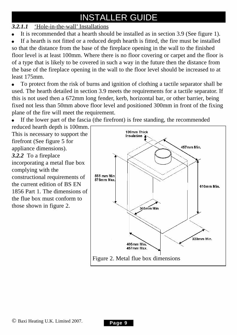
3.2.1.1 ‘Hole-in-the-wall’ Installations! It is recommended that a hearth should be installed as in section 3.9 (See figure 1). ! If a hearth is not fitted or a reduced depth hearth is fitted, the fire must be installedso that the distance from the base of the fireplace opening in the wall to the finishedfloor level is at least 100mm. Where there is no floor covering or carpet and the floor isof a type that is likely to be covered in such a way in the future then the distance fromthe base of the fireplace opening in the wall to the floor level should be increased to atleast 175mm.! To protect from the risk of burns and ignition of clothing a tactile separator shall beused. The hearth detailed in section 3.9 meets the requirements for a tactile separator. Ifthis is not used then a 672mm long fender, kerb, horizontal bar, or other barrier, beingfixed not less than 50mm above floor level and positioned 300mm in front of the fixingplane of the fire will meet the requirement.! If the lower part of the fascia (the firefront) is free standing, the recommendedreduced hearth depth is 100mm.This is necessary to support thefirefront (See figure 5 forappliance dimensions). 3.2.2 To a fireplaceincorporating a metal flue boxcomplying with theconstructional requirements ofthe current edition of BS EN1856 Part 1. The dimensions ofthe flue box must conform tothose shown in figure 2.
Page 9
INSTALLER GUIDE
© Baxi Heating U.K. Limited 2007.
Figure 2. Metal flue box dimensions
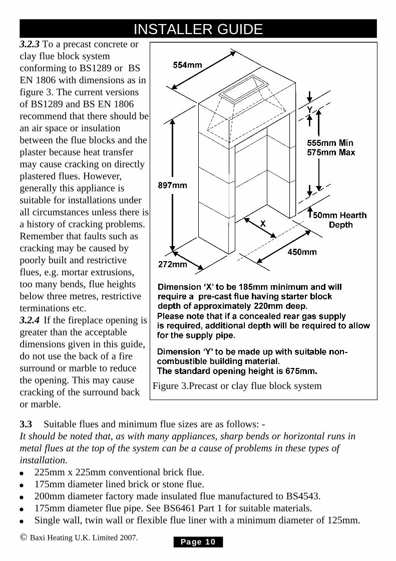
3.2.3 To a precast concrete orclay flue block systemconforming to BS1289 or BSEN 1806 with dimensions as infigure 3. The current versionsof BS1289 and BS EN 1806recommend that there should bean air space or insulationbetween the flue blocks and theplaster because heat transfermay cause cracking on directlyplastered flues. However,generally this appliance issuitable for installations underall circumstances unless there isa history of cracking problems.Remember that faults such ascracking may be caused bypoorly built and restrictiveflues, e.g. mortar extrusions,too many bends, flue heightsbelow three metres, restrictiveterminations etc.3.2.4 If the fireplace opening isgreater than the acceptabledimensions given in this guide,do not use the back of a firesurround or marble to reducethe opening. This may causecracking of the surround backor marble.
3.3 Suitable flues and minimum flue sizes are as follows: - It should be noted that, as with many appliances, sharp bends or horizontal runs inmetal flues at the top of the system can be a cause of problems in these types ofinstallation.! 225mm x 225mm conventional brick flue.! 175mm diameter lined brick or stone flue.! 200mm diameter factory made insulated flue manufactured to BS4543.! 175mm diameter flue pipe. See BS6461 Part 1 for suitable materials.! Single wall, twin wall or flexible flue liner with a minimum diameter of 125mm.
Page 10
INSTALLER GUIDE
© Baxi Heating U.K. Limited 2007.
Figure 3.Precast or clay flue block system

The materials to be used are stainless steel or aluminium as specified in BS EN 1856Part 1 or BS715. The liner must be sealed to the surrounding area above the fireplaceopening and to the top of the chimney. An approved terminal must be fitted.! A properly constructed precast concrete or clay flue system conforming to BS1289or BS EN 1806. This system is only suitable if the conditions stated in section 3.2.3 aremet.
3.4 The flue must conform to BS 5440: Part 1 in design and installation.The flue, measured from the bottom of the fireplace opening to the bottom of theterminal, shall be not less than 3m in actual vertical height. When calculated inaccordance with BS 5440: Part 1 Annex A, the minimum equivalent height of the flueshall be 2.0m of 125mm dia. flue pipe.
3.5 The flue must not be used for any other appliance or application.
3.6 Any chimney damper or restrictor should be removed. If removal is not possible,they must be secured in the open position.
3.7 If the appliance is intended to be installed to a chimney that was previously usedfor solid fuel, the flue must be swept clean prior to installation. All flues should beinspected for soundness and freedom from blockages.
3.8 If the fireplace opening is an underfloor draught type, it must be sealed to stop anydraughts.
3.9 The appliance must be mounted behind a non-combustible hearth (N.B.conglomerate marble hearths are considered as non-combustible) unless the conditionsof section 3.2.1.1 are met. The appliance can be fitted to a purpose made proprietaryclass “O”-150°C surround. The hearth material must be at least 12mm thick. Theperiphery of the hearth (or fender) should be at least 50mm above floor level todiscourage the placing of carpets or rugs over it.The surface of the hearth must be sufficiently flat to enable the bottom of the frontsurround and the bottom front cover to be aligned horizontally. Any excessiveunevenness (uneven tiles, Cotswold stone, etc.) should be rectified. The appliance mustnot stand on combustible materials or carpets.
3.10 The front face of the fireplace should be reasonably flat over the area covered bythe hotbox top and side flange seals to ensure good sealing. These faces should be madegood if necessary. The fireplace floor should be reasonably flat to ensure that a goodseal with the hotbox can be made.
Page 11
INSTALLER GUIDE
© Baxi Heating U.K. Limited 2007.
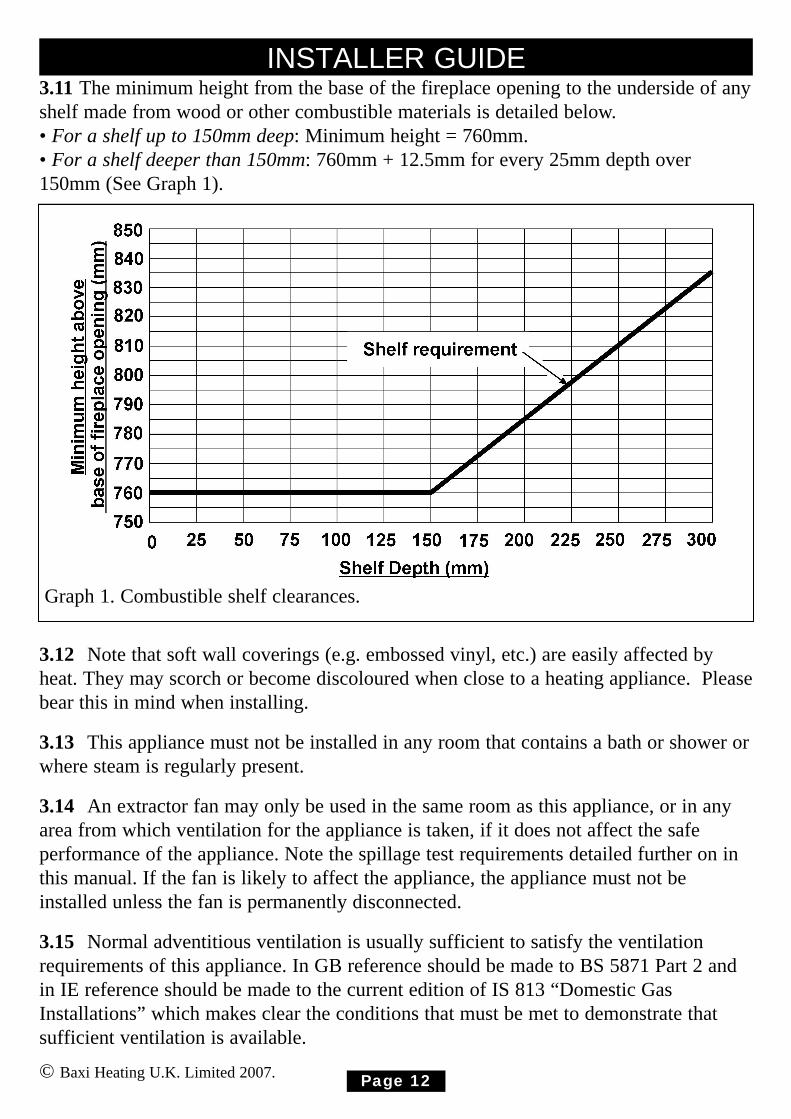
3.11 The minimum height from the base of the fireplace opening to the underside of anyshelf made from wood or other combustible materials is detailed below.• For a shelf up to 150mm deep: Minimum height = 760mm.• For a shelf deeper than 150mm: 760mm + 12.5mm for every 25mm depth over150mm (See Graph 1).
3.12 Note that soft wall coverings (e.g. embossed vinyl, etc.) are easily affected byheat. They may scorch or become discoloured when close to a heating appliance. Pleasebear this in mind when installing.
3.13 This appliance must not be installed in any room that contains a bath or shower orwhere steam is regularly present.
3.14 An extractor fan may only be used in the same room as this appliance, or in anyarea from which ventilation for the appliance is taken, if it does not affect the safeperformance of the appliance. Note the spillage test requirements detailed further on inthis manual. If the fan is likely to affect the appliance, the appliance must not beinstalled unless the fan is permanently disconnected.
3.15 Normal adventitious ventilation is usually sufficient to satisfy the ventilationrequirements of this appliance. In GB reference should be made to BS 5871 Part 2 andin IE reference should be made to the current edition of IS 813 “Domestic GasInstallations” which makes clear the conditions that must be met to demonstrate thatsufficient ventilation is available.
Page 12
INSTALLER GUIDE
© Baxi Heating U.K. Limited 2007.
Graph 1. Combustible shelf clearances.

3.16 Propane gas appliances must not be installed in a room that is built entirely belowground level (See BS 5871 Part 2).
3.17 If the appliance is to be fitted against awall with combustible cladding, the claddingmust be removed from the area covered by thefascia. The cladding must also not touch thefascia (See figure 4). We suggest that the fasciais used as a template to mark the area forcombustible cladding removal and that thisarea is increased by at least 2mm all round.
3.18 Proprietary terminals must comply withBS 715 or BS 1289. Any terminal ortermination must be positioned in accordancewith BS 5440 Part 1 to ensure that the productsof combustion can be safely dispersed into theoutside atmosphere. Where the appliance isconnected to an unlined brick chimney it isgenerally unnecessary for the chimney pot tobe replaced or for a terminal to be fitted unlessthe flue has a diameter smaller than 170mm.
3.19 The appliance is fitted with an A.S.D (Atmosphere sensing device). If theappliance closes down after a period of operation for no apparent reason, the consumershould be informed to stop using the appliance until the installation and appliance havebeen thoroughly checked. The A.S.D will shut the appliance down if an unacceptableamount of harmful products of combustion accumulate. Under no circumstances shouldthe A.S.D be altered or bypassed in any way. Only a genuine manufacturers replacementpart should be fitted. The individual A.S.D components are not replaceable.
3.20 A fireguard complying with BS 8423 should be fitted for the protection of youngchildren, the elderly, the infirm or pets.
3.21 The minimum allowable distance from the outside of the appliance fascia to acorner wall having combustible material or any other combustible surface whichprojects beyond the front of the appliance is shown in figure 5.
Page 13
INSTALLER GUIDE
© Baxi Heating U.K. Limited 2007.
Figure 4. Removal of combustiblecladding (Fascia may differ from thatshown).

Page 14
INSTALLER GUIDE
© Baxi Heating U.K. Limited 2007.
Figure 5. Appliance dimensions and clearances (Dimensions are subject tomanufacturing deviation. Fascia may differ from that shown).
Key
A B C D E
Model Height(mm)
Width(mm)
Depthintoroom(mm)
Minimummandatoryclearance tocombustible
surfaces projectingbeyond the front of
appliance (mm).
Recommendedclearance to non-
combustible surfacesfor access purposes
(mm).
Blenheim &Sonnet 599 492 65 125 10
Anthem,Camden &
Seattle599 492 71 125 10
Prelude 599 492 76 125 10
Minima 599 492 75 125 10
Bolero 636 518 94 100 10
Westminster 605 500 50 100 10
Victorian 612 515 70 100 10

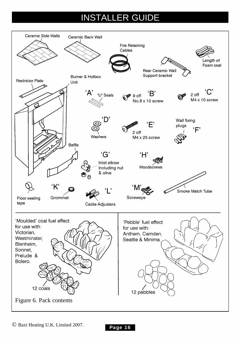
4. PACK CONTENTSThe items required for this appliance are packed in two sections.Remove all the items carefully to prevent damage. Take special care when handling theceramic components. Some items may be contained in the packaging fitments -Examine the packaging carefully before discarding. Check that all the items are presentand undamaged.Items below with a letter reference are supplied on a film wrapped card.
Section 1 - Fire Unit contains:(See figure 6).
1 Burner and hotbox unit.2 ‘A’ Small “U” seals for hotbox side flanges.9 ‘B’ screws (No. 8 x 10).2 ‘C’ screws (M4 x 10).2 ‘D’ washers (For fascia hanging Bolero).2 ‘E’ screws (M4 x 25) (For fascia hanging on Bolero and Westminster only).6 ‘F’ Wall fixing plugs.1 ‘G’ Inlet elbow including pressure test point, nut and olive.4 ‘H’ Woodscrews1 ‘K’ Grommet.2 ‘L’ Cable adjusters.4 ‘M’ Eyescrews.1 Burner front baffle (Supplied with all models but required on Blenheim, Bolero,
Camden, Seattle, Prelude, Sonnet and Victorian models only).1 Flue restrictor plate.1 Ceramic back wall.1 Pair of ceramic side walls.1 Ceramic fuel effect pack.1 Strip of floor sealing tape.2 Fire retaining cables.1 Smoke match tube.1 Rear ceramic wall support bracket.1 Length of self adhesive foam seal.1 Literature pack.
Page 15
INSTALLER GUIDE
© Baxi Heating U.K. Limited 2007.
Page 16
INSTALLER GUIDE
© Baxi Heating U.K. Limited 2007.
Figure 6. Pack contents

Page 17
INSTALLER GUIDE
© Baxi Heating U.K. Limited 2007.
Section 2 - Bolero:1 Fascia 1 Firefront casting1 Bottom front cover casting.
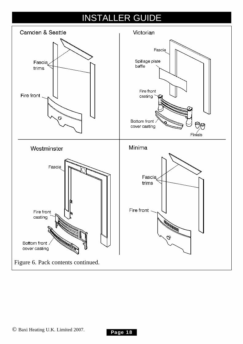
Figure 6. Pack contents continued.
Section 2 - Anthem & Prelude:1 Fascia trim pack (Contains three
separate pieces and six magnets)1 Firefront casting1 Bottom front cover casting.
Section 2 - Sonnet and Blenheim:1 Fascia trim pack (Contains three
separate pieces and six magnets)1 Firefront casting1 Bottom front cover casting.
Section 2 - Victorian:1 Fascia1 Firefront casting2 Finials1 Bottom front cover casting1 Spillage plate cover and four magnets
Section 2 - Camden, Seattle & Minima:1 Fascia trim pack (Contains three
separate pieces and six magnets)1 Firefront
Section 2 - Westminster:1 Fascia1 Firefront casting1 Bottom front cover casting
Page 18
INSTALLER GUIDE
© Baxi Heating U.K. Limited 2007.
Figure 6. Pack contents continued.

5. FIREPLACE CHECK5.1 Fireplace check.5.1.1 Fireplace size The fireplace must complywith the requirementsdescribed in section 3.2.This will probably entailremoving the fireback andinfill material behind thefireback. The debriscatchment area shown infigure 7 must be kept clearof obstructions.5.1.2 Fireplace generalconditionThe fireplace floor shouldbe reasonably flat to ensurethat the hotbox can beinstalled without it rocking and so that a good seal can be made at the bottom front ofthe box. The front face of the fireplace should be reasonably flat over the area coveredby the hotbox top and side flange seals to ensure good sealing. These faces should be
Page 19
INSTALLER GUIDE
© Baxi Heating U.K. Limited 2007.
Figure 7. Fireplace area.
Figure 6. Pack contents continued.

made good if necessary. If the appliance is to be fitted against a wall with combustiblecladding, the cladding must be removed from the area covered by the fascia. Thecladding must also not touch the fascia (See figure 4). We suggest that the fascia is usedas a template to mark the area for combustible cladding removal and that this area isincreased by at least 2mm all round.5.1.3 Soundness for appliance attachmentTwo primary methods of retaining the appliance are provided: -1) By fixing to the fireplace front surround.2) Using concealed tension cables fixed to the rear of the fireplace opening togetherwith secondary fixing to the fireplace floor.The methods are detailed in section 9 of this guide. Before selecting the retentionmethod, consult with the customer. Method 2 is provided for instances where drillingholes in the front surface of the fireplace surround is unacceptable to the customer orotherwise impractical. N.B. It is unwise to attempt to drill into marble without theproper tools and equipment.If method 1 is chosen, make sure that the front surround area is sound enough to takethe wall plugs and wood screws . If necessary, make sound with a suitable cement.If method 2 is chosen, make sure that the areas at the back and towards the centre of thefireplace floor are sound enough to take the eyescrews and wood screws . If these areashave deteriorated due to prolonged use, they should be made sound with a suitablecement.5.1.4 Installations using a metal flue boxThe whole of the top surface of the metal flue box must be covered with a minimum100mm layer of mineral wool or equivalent insulation (See figure 2).
5.2 Fireplace flue pull.Close all doors and windows in the room in which the appliance is to be installed. Afterconfirming with a match that smoke is drawn into the flue, light a 13 gram smoke pelletand check that there is a definite flow through the flue. Verify outside that the smokeexits from one terminal only and that the termination is suitable. Observe, wherepossible, upstairs rooms and loft spaces for signs of escaping smoke indicating adefective flue. If there is not a definite flow warm the flue for a few minutes and repeatthe smoke pellet test. If there is still no definite flow the flue may need remedial work –Do not fit the appliance until there is a definite flow through the flue.
Page 20
INSTALLER GUIDE
© Baxi Heating U.K. Limited 2007.

6. IGNITION CHECK
Before attempting to install, it is worth checking that the ignition system performssatisfactorily.Set the control knob to the offposition.Depress the control knob and rotateit anticlockwise to the pilot ignitionposition. A 'click' will be heard asthe integral piezo operates. A sparkshould be seen between the electrodeand pilot tip. If there is no sparkcheck the following: -! Ensure that the electrode lead is connected to the terminal at the base of theelectrode.! If the above is correct, check for damage to the electrode lead.
7. GAS SUPPLY CONNECTION
A nut and olive are provided for an 8mm pipe inlet connection to the inlet elbow at thebottom front of the appliance. The elbow can be rotated to allow a connection from anydirection. The elbow includes a valve for isolating the gas supply and a pressure testpoint.The supply pipe must be rigid material. Flexible pipe must not be used.Concealed supply pipe connectionIf a concealed connection from inside the fireplace is required then, before theappliance is fitted into the fireplace it will be necessary to extend the supply line sothat it will project through the hole in the back of the hotbox and run to the inlet elbowat the front. The pipe run from the supply line up to the rear opening in the hotbox mustbe kept away from the area which will be taken by the hotbox when it is installed (Seefigure 7).Note that the centre of the appliance inlet elbow is 25mm above the fireplace floor. Theinlet elbow ‘G’ should be fitted to the supply pipe at this stage.
Page 21
INSTALLER GUIDE
© Baxi Heating U.K. Limited 2007.
Figure 8. Ignition operation

8. PREPARING APPLIANCE FOR INSTALLATION
IMPORTANTBefore continuing with the installation of this gas fire the aeration setting onthe burner must be checked. The aeration is factory set, but will requireadjustment. See section 17.1 (Servicing and parts replacement).
1. Detach the burner unit from thehotbox by removing two screws (Seefigure 9). Lift the burner unit clear.2. Fit the two U- seals ‘A’ to thebottom edges of the hotbox sideflanges (See figure 10).3. It is important that the grommet‘K’ supplied in the loose parts packis fitted to the hole in the rear of thehotbox.
For concealed connection only: 4. Pierce the grommet to allow the pipe to pass through it.The grommet should envelop the pipe. If the hole is largerthan the pipe, seal it with tape. Do not pierce thegrommet unless the supply pipe is to pass through it.5. This appliance is supplied with a flue restrictor for usewhere the flue draught is excessive. The restrictor mustNOT be fitted where a precast flue or a flue liner is used.For all other installations the restrictor should be fitted.There may however, be certain exceptional circumstanceswhere fitting the restrictor causes the fire to fail thespillage test. In such cases the restrictor will have to beremoved. After removalconduct the spillage checkagain.The restrictor is packedloose with the appliance andis secured with the twoscrews used for the downdraft baffle. Remove the twoscrews from the rear of theappliance (See figure 11).
Page 22
INSTALLER GUIDE
© Baxi Heating U.K. Limited 2007.
Figure 11. Flue restrictor
Figure 10. U- Seals
Figure 9. Burner attachment points
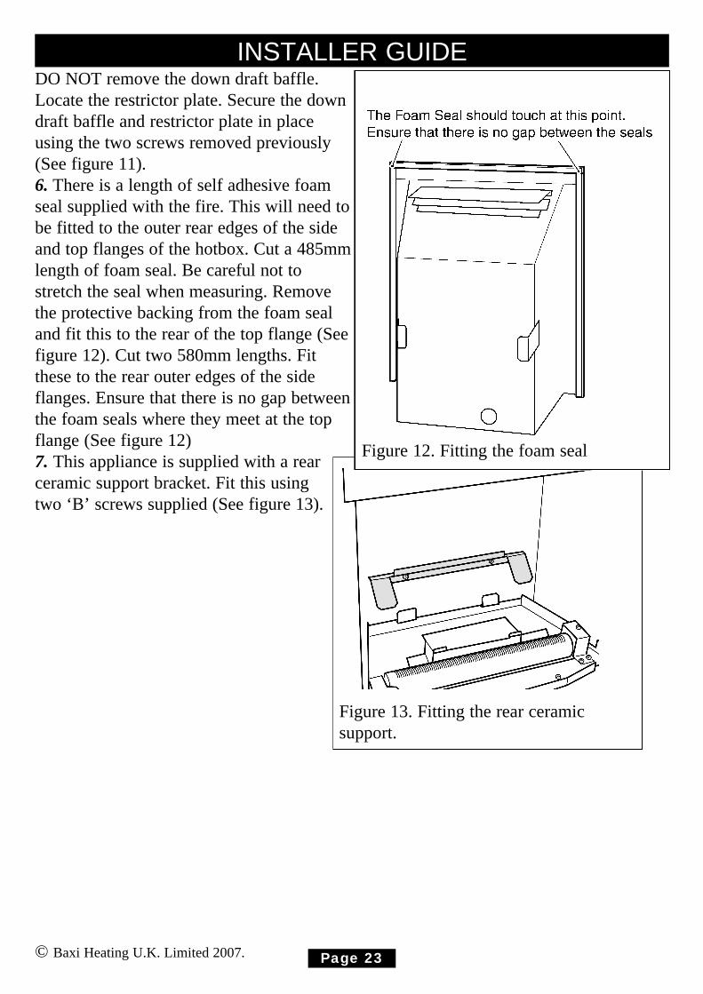
DO NOT remove the down draft baffle.Locate the restrictor plate. Secure the downdraft baffle and restrictor plate in placeusing the two screws removed previously(See figure 11).6. There is a length of self adhesive foamseal supplied with the fire. This will need tobe fitted to the outer rear edges of the sideand top flanges of the hotbox. Cut a 485mmlength of foam seal. Be careful not tostretch the seal when measuring. Removethe protective backing from the foam sealand fit this to the rear of the top flange (Seefigure 12). Cut two 580mm lengths. Fitthese to the rear outer edges of the sideflanges. Ensure that there is no gap betweenthe foam seals where they meet at the topflange (See figure 12)7. This appliance is supplied with a rearceramic support bracket. Fit this usingtwo ‘B’ screws supplied (See figure 13).
Page 23
INSTALLER GUIDE
© Baxi Heating U.K. Limited 2007.
Figure 13. Fitting the rear ceramicsupport.
Figure 12. Fitting the foam seal

9. HOTBOX INSTALLATION
9.1 Method 1 - Front fixing to fireplace surround.1. Make sure that the fireplace front surroundarea is sound enough to take the fibre wallplugs ‘F' and wood screws ‘H’. If necessary,make sound with a suitable cement.2. Place the hotbox centrally in the fireplacein the position in which it is to bepermanently installed. If a concealedconnection is being used, insert the hotboxinto the fireplace feeding the supply pipethrough the pierced hole in the rear grommet.3. Mark the fireplace front surround throughthe four fixing holes in the side flanges of thehotbox (See figure 14).4. Remove the hotbox. Drillfour holes in the fireplace frontsurround at the markedpositions using a no.12 masonrydrill.5. Insert a fibre wall plug ‘F’into each hole.6. Place the hotbox back inposition in the fireplace.7. Fit a wood screw ‘H’ througheach hole in the hotbox flangesand tighten to seal the box tothe fireplace surround.
9.2 Method 2 - Cable retentionand floor fixing.1. Make sure that the relevantareas at the fireplace back orfloor are sound enough to takethe eyescrews ‘M’ and woodscrews ‘H’. If these areas havedeteriorated due to prolongeduse they should be made soundwith a suitable cement.
Page 24
INSTALLER GUIDE
© Baxi Heating U.K. Limited 2007.
Figure 15. Eyescrew positions
Figure 14. Front fixing

2. Drill four holes in the rear wall of the fireplace for the fibre wall plugs ‘F’. The holesshould be drilled within the range of positions shown in figure 15 using a no.12masonry drill. The holes should be equidistant each side of the centre line of thefireplace to ensure that the appliance finishescentrally in the opening when tension is applied tothe cables.3. Insert a fibre wall plug into each hole. Use thefibre plugs supplied with this appliance - Never useplastic plugs instead of the fibre plugs supplied.Screw the eyescrews ‘M’ into the plugs. Make surethat the eyescrews are secure.4. Place the hotbox unit close to the fireplace butallow sufficient access into the fireplace opening sothat the cables can be threaded through the eyescrewsand returned through the back of the hotbox. If aconcealed connection is being used, insert the hotboxinto the fireplace feeding the supply pipe through thepierced hole in the rear grommet.5. The hotbox has two holes at each side of the spillageplate. Insert one end of each cable (one cable each side)from the back through the lower of the two holes andreturn the end through the upper of the holes (See figure16). Give the cables a pull so that they grip against thehotbox flanges.6. Thread the cables through the eyescrews. Return thecables through the holes near the bottom of the hotboxback panel (See figure 17) (For precast or clay blockflue systems return the cables through the slottedholes in the side of the hotbox).7. Place the hotbox fully back into the fireplaceopening so that it is sealed against the fireplace frontsurround.8. Drill a hole into the fireplace floor through each ofthe two holes in the base of the hotbox using a no.12masonry drill (See figure 18).9. Insert a fibre wall plug into each hole. Fit a woodscrew ‘H’ in each plug and tighten.Always screw the base into position before applyingtension to the cables. This will ensure a tight sealbetween the top of the hotbox and wall 10. Fit a cable adjuster ‘L’ over the bottom end of each
Page 25
INSTALLER GUIDE
© Baxi Heating U.K. Limited 2007.
Figure 18. Floor fixing
Figure 17. Cable route
Figure 16. Upper cable retention

cable.11. Pull each cable taut. Push the cableadjusters hard up against the back panel. Theend of the cable adjuster will pass into the hole.Tighten the screws in the adjusters so that theyclamp the cables in position. Apply tension tothe cables by turning the hexagonal adjusters byhand (See figure 19).12. Inspect the installation of the hotbox againstthe fireplace surround. If the hotbox is alignedsquarely and the sealing is satisfactory, fullytighten the cable adjusters.13. If the hotbox is not correctly aligned,release the tension on the cables by slackeningthe screws and turning the hexagonal adjustersfully anticlockwise. The hotbox should thenautomatically realign itself. Pull each cable tautagain and push the cable adjusters back againstthe back panel. Again, tighten the screws in theadjusters and apply tension to the cables byturning the hexagonal adjusters clockwise as faras possible.14. Feed the free length of the cables into thegap between the inner and outer back panels sothat they are available to allow easy removal andrefitting of the appliance during subsequent servicecalls. Do not cut off the free lengths of cable. Onprecast flue installations feed the cables into thesmall holes at the base of the side panels (Seefigure 19)
9.3 Sealing floor front - All installations.Using the floor sealing tape supplied, seal thebottom of the hotbox to the fireplace and hearthfloor (See figure 20).Make sure that the whole length of the frontedge of the hotbox is fully sealed.
Page 26
INSTALLER GUIDE
© Baxi Heating U.K. Limited 2007.
Figure 20. Floor sealing
Figure 19. Lower cable retention
Side entry Rear entry
10. BURNER & SUPPLY PIPE INSTALLATION
10.1 Burner and supply pipe installation.1. Refit the burner unit to the hotbox with two screws.2. Connect the supply line to the appliance.3. Turn on the gas supply and pressure check the installation pipework for gassoundness. In the United Kingdom (GB) check in accordance with the current edition ofBS 6891. In the Republic of Ireland check in accordance with the current edition of IS813 “Domestic Gas Installations”.
10.2 Preliminary burner checks.Some burner operations can be checked at this stage. Checking now will mean that lessdisassembly will be required if any problems are found. A full check should still bemade, however, after final installation.
10.2.1 Lighting the burner.1. If closed, open the isolating valve at the inlet elbow.2. Depress the control knob and rotate it anticlockwise to the pilot ignition position. A'click' will be heard as the integral piezo operates. A spark should be seen between theelectrode and pilot tip.3. Turn the control knob clockwise to the 'Off' position. Repeat this operation until aflame appears at the pilot. There may be a delay before the pilot lights due to air beingpurged from the system. When a flame appears at the pilot keep the control knobdepressed and hold the pilot ignition position for five seconds. When the control knob isreleased the pilot flame should remain lit.
10.2.2 Operating the burner.1. When the pilot burner is operating properly, gradually turn the control knob anti-clockwise to 'HIGH' (Depress the knob slightly to get past the pilot ignition position).The main burner should now light. Depress the control knob slightly to release from the'HIGH' position and turn back (clockwise) to 'LOW'. While turning, the burner flamesshould gradually become lower but remain alight. Depress the control knob slightly torelease from the 'LOW' position and turn back (clockwise) to the ‘Pilot ignition’position. The main burner should extinguish but the pilot should remain alight. Depressthe control knob slightly and turn back (clockwise) to turn OFF. This will extinguish the pilot.
If the above checks are satisfactory, continue with the installation. If not, check thecontrol and ignition circuitry and components as described in the servicing section ofthis guide.
Page 27
INSTALLER GUIDE
© Baxi Heating U.K. Limited 2007.

10.3 Inlet pressure check.The appliance is pre-set to give the correct heat inputat the inlet pressure shown in section 2 of thismanual. No adjustment is necessary. 1. Check the inlet pressure by fitting a pressuregauge at the test point. The test point is on the inletelbow (See figure 21). Check the pressure with theappliance alight and set at maximum output.2. After checking, turn off the appliance. Remove thepressure gauge and replace the test point sealingscrew.3. Relight the appliance. Turn to the maximumoutput position and test around the sealing screw for gas soundness with a suitable leakdetection fluid.
When the above checks from section 10.2 and 10.3 have been completed close theisolating valve on the inlet elbow.
11. CERAMIC WALLS INSTALLATION
1. Fit the ceramic rear wall inside the “L”bracket on the back face of the burnercompartment. Push the ceramic wall flatagainst the back face of the burnercompartment (See figure 22).2. Fit the ceramic side walls against the sidefaces of the burner compartment. The bottomedges of the walls should rest in the ledges atthe sides of the firebox. Slide them in fromthe front and ensure thatthey touch the rear wall. Becareful not to damage theedges of the side walls (Seefigure 23).
Page 28
INSTALLER GUIDE
© Baxi Heating U.K. Limited 2007.
Figure 23. Ceramic side walls installation
Figure 22. Ceramic rear wall installation
Figure 21. Pressure test point
12. FITTING THE FASCIA
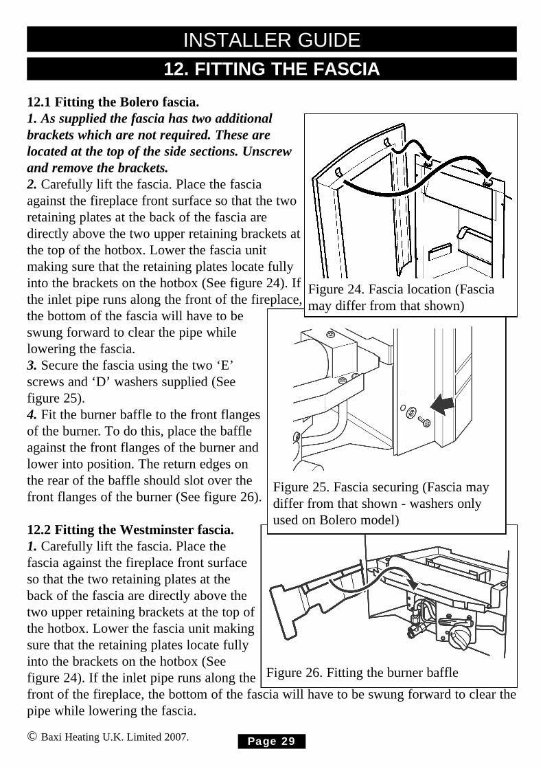
12.1 Fitting the Bolero fascia.1. As supplied the fascia has two additionalbrackets which are not required. These arelocated at the top of the side sections. Unscrewand remove the brackets. 2. Carefully lift the fascia. Place the fasciaagainst the fireplace front surface so that the tworetaining plates at the back of the fascia aredirectly above the two upper retaining brackets atthe top of the hotbox. Lower the fascia unitmaking sure that the retaining plates locate fullyinto the brackets on the hotbox (See figure 24). Ifthe inlet pipe runs along the front of the fireplace,the bottom of the fascia will have to beswung forward to clear the pipe whilelowering the fascia.3. Secure the fascia using the two ‘E’screws and ‘D’ washers supplied (Seefigure 25).4. Fit the burner baffle to the front flangesof the burner. To do this, place the baffleagainst the front flanges of the burner andlower into position. The return edges onthe rear of the baffle should slot over thefront flanges of the burner (See figure 26).
12.2 Fitting the Westminster fascia.1. Carefully lift the fascia. Place thefascia against the fireplace front surfaceso that the two retaining plates at theback of the fascia are directly above thetwo upper retaining brackets at the top ofthe hotbox. Lower the fascia unit makingsure that the retaining plates locate fullyinto the brackets on the hotbox (Seefigure 24). If the inlet pipe runs along thefront of the fireplace, the bottom of the fascia will have to be swung forward to clear thepipe while lowering the fascia.
Page 29
INSTALLER GUIDE
© Baxi Heating U.K. Limited 2007.
Figure 26. Fitting the burner baffle
Figure 25. Fascia securing (Fascia maydiffer from that shown - washers onlyused on Bolero model)
Figure 24. Fascia location (Fasciamay differ from that shown)
2. Secure the fascia using the two ‘C’ screwssupplied (See figure 25).
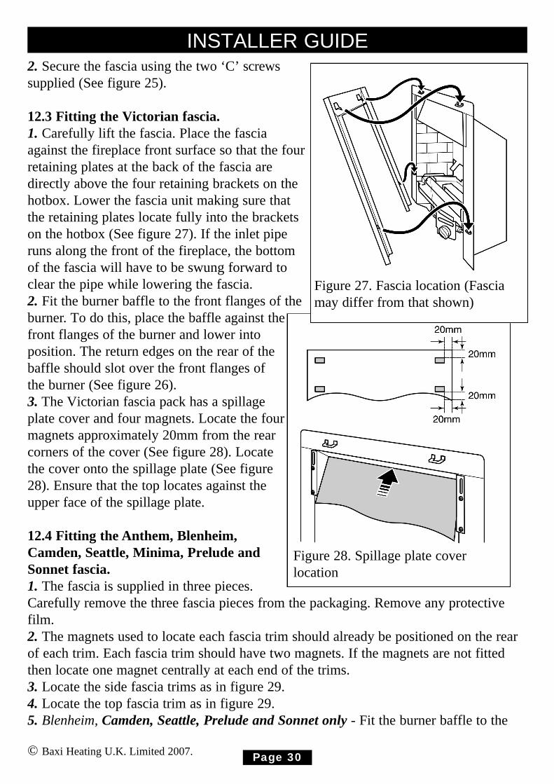
12.3 Fitting the Victorian fascia.1. Carefully lift the fascia. Place the fasciaagainst the fireplace front surface so that the fourretaining plates at the back of the fascia aredirectly above the four retaining brackets on thehotbox. Lower the fascia unit making sure thatthe retaining plates locate fully into the bracketson the hotbox (See figure 27). If the inlet piperuns along the front of the fireplace, the bottomof the fascia will have to be swung forward toclear the pipe while lowering the fascia.2. Fit the burner baffle to the front flanges of theburner. To do this, place the baffle against thefront flanges of the burner and lower intoposition. The return edges on the rear of thebaffle should slot over the front flanges ofthe burner (See figure 26).3. The Victorian fascia pack has a spillageplate cover and four magnets. Locate the fourmagnets approximately 20mm from the rearcorners of the cover (See figure 28). Locatethe cover onto the spillage plate (See figure28). Ensure that the top locates against theupper face of the spillage plate.
12.4 Fitting the Anthem, Blenheim,Camden, Seattle, Minima, Prelude andSonnet fascia.1. The fascia is supplied in three pieces.Carefully remove the three fascia pieces from the packaging. Remove any protectivefilm.2. The magnets used to locate each fascia trim should already be positioned on the rearof each trim. Each fascia trim should have two magnets. If the magnets are not fittedthen locate one magnet centrally at each end of the trims. 3. Locate the side fascia trims as in figure 29.4. Locate the top fascia trim as in figure 29.5. Blenheim, Camden, Seattle, Prelude and Sonnet only - Fit the burner baffle to the
Page 30
INSTALLER GUIDE
© Baxi Heating U.K. Limited 2007.
Figure 28. Spillage plate coverlocation
Figure 27. Fascia location (Fasciamay differ from that shown)
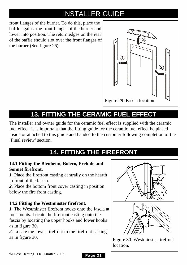
front flanges of the burner. To do this, place thebaffle against the front flanges of the burner andlower into position. The return edges on the rearof the baffle should slot over the front flanges ofthe burner (See figure 26).
13. FITTING THE CERAMIC FUEL EFFECTThe installer and owner guide for the ceramic fuel effect is supplied with the ceramicfuel effect. It is important that the fitting guide for the ceramic fuel effect be placedinside or attached to this guide and handed to the customer following completion of the‘Final review’ section.
14. FITTING THE FIREFRONT
14.1 Fitting the Blenheim, Bolero, Prelude andSonnet firefront.1. Place the firefront casting centrally on the hearthin front of the fascia. 2. Place the bottom front cover casting in positionbelow the fire front casting.
14.2 Fitting the Westminster firefront.1. The Westminster firefront hooks onto the fascia atfour points. Locate the firefront casting onto thefascia by locating the upper hooks and lower hooksas in figure 30. 2. Locate the lower firefront to the firefront castingas in figure 30.
Page 31
INSTALLER GUIDE
© Baxi Heating U.K. Limited 2007.
Figure 29. Fascia location
Figure 30. Westminster firefrontlocation.
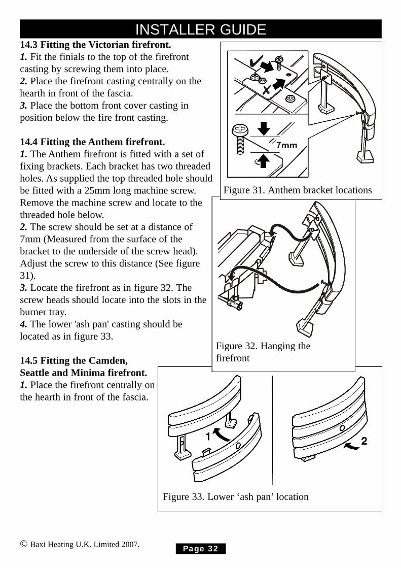
14.3 Fitting the Victorian firefront.1. Fit the finials to the top of the firefrontcasting by screwing them into place.2. Place the firefront casting centrally on thehearth in front of the fascia. 3. Place the bottom front cover casting inposition below the fire front casting.
14.4 Fitting the Anthem firefront.1. The Anthem firefront is fitted with a set offixing brackets. Each bracket has two threadedholes. As supplied the top threaded hole shouldbe fitted with a 25mm long machine screw.Remove the machine screw and locate to thethreaded hole below.2. The screw should be set at a distance of7mm (Measured from the surface of thebracket to the underside of the screw head).Adjust the screw to this distance (See figure31).3. Locate the firefront as in figure 32. Thescrew heads should locate into the slots in theburner tray. 4. The lower 'ash pan' casting should belocated as in figure 33.
14.5 Fitting the Camden,Seattle and Minima firefront.1. Place the firefront centrally onthe hearth in front of the fascia.
Page 32
INSTALLER GUIDE
© Baxi Heating U.K. Limited 2007.
Figure 33. Lower ‘ash pan’ location
Figure 32. Hanging thefirefront
Figure 31. Anthem bracket locations
15. FULL OPERATING CHECKS15.1 Check the control settings.With the ceramic fuel effect in position the control operation must now be fullyrechecked. Make sure that the isolating valve at the elbow is open.! When first turned on from cold, the flames will appear predominantly blue.! When operating the fire for the first time, some vapours may be given off whichcould set off smoke alarms in the vicinity. These vapours are quite normal with newappliances. They are totally harmless and will disappear after a few hours use.
15.1.1 Lighting the burner.1. If closed, open the isolating valve at the inlet elbow.2. Depress the control knob and rotate it anticlockwise to the pilot ignition position. A'click' will be heard as the integral piezo operates. A spark should be seen between theelectrode and pilot tip.3. Turn the control knob clockwise to the 'Off' position. Repeat this operation until aflame appears at the pilot. There may be a delay before the pilot lights due to air beingpurged from the system. When a flame appears at the pilot keep the control knobdepressed and hold the pilot ignition position for five seconds. When the control knob isreleased the pilot flame should remain lit.
15.1.2 Operating the burner.1. When the pilot burner is operating properly, gradually turn the control knob anti-clockwise to 'HIGH' (Depress the knob slightly to get past the pilot ignition position).The main burner should now light. Depress the control knob slightly to release from the'HIGH' position and turn back (clockwise) to 'LOW'. While turning, the burner flamesshould gradually become lower but remain alight. Depress the control knob slightly torelease from the 'LOW' position and turn back (clockwise) to the Pilot ignition position.The main burner should extinguish but the pilot should remain alight. Depress thecontrol knob slightly and turn back (clockwise) to turn OFF. This will extinguish the pilot.
If the above checks are satisfactory, continue with the installation. If not, check thecontrol and ignition circuitry and components as described in the servicing section ofthis guide.While cooling the ceramic fuel effect may make some crackling noises. This is quitenormal.
Page 33
INSTALLER GUIDE
© Baxi Heating U.K. Limited 2007.

15.2 Check for spillage.
1. Close all doors and windows in the room containing the appliance.2. Light the appliance and turn the control knob to the ‘HIGH’ position.3. Leave the appliance on for five minutes.4. The smoke match should be placedhorizontally into the hotbox at the right handside (See figure 34). The installation is satisfactory if the smoke isdrawn into the appliance.If the smoke is not drawn into the applianceleave the appliance alight at the maximumsetting for a further ten minutes and thenrepeat the test. If the smoke is still not drawninto the appliance inspect the sealing to thefireplace surround. If the sealing is satisfactorybut the appliance is installed with the fluerestrictor (See section 8 point 5) remove therestrictor, reseal the appliance and retest. Ifsmoke is still not drawn into the appliancedisconnect the appliance and seek expertadvice.5. If the above test is satisfactory open all internal connecting doors, hatches, etc. in theroom. Keep all doors and windows that open to the outside of the building closed.Recheck for spillage as above. If an extractor fan is installed in the same room as theappliance or a connecting room, check that spillage does not occur with the fanoperating and all doors and other openings between the fan and the appliance open.If the smoke is drawn into the appliance, continue with the installation. If the test is notsatisfactory disconnect the appliance and advise the customer of the cause offailure.
15.3 Flame supervision and spillage monitoring system.The pilot unit incorporates a system that will automatically shut off the gas supply if thepilot flame goes out or if there is insufficient oxygen due to spillage or lack ofventilation.Check that the system operates properly as follows;
Page 34
INSTALLER GUIDE
© Baxi Heating U.K. Limited 2007.
A spillage check must be made before leaving the installed appliance with thecustomer. Make this with all the ceramic fuel effect pieces and the firefront in
position
Figure 34. Smoke match tube position(Fascia may differ from that shown).

! Light the appliance. Set at the “HIGH” position and leave for one minute.! Turn back to “OFF” to extinguish the pilot. Note the time when the pilot goes out.Listen for a snap sound at the gas tap. Note the time when the sound is heard. Thissound is caused by an electromagnetic valve shutting off the gas supply through the tap.The valve is located in the body of the tap. The valve should operate within 60 secondsof the pilot going out. If the valve does not operate within this time limit do not allowthe appliance to be used until the fault has been corrected.This monitoring system must not be adjusted, bypassed or put out of operation.This monitoring system, or any of its parts, must only be exchanged using BaxiFires Division authorised parts.
16. FINAL REVIEW
1. If a gap is visible between the inner sides of the fascia and the ceramic side walls,gently slide the walls forward.2. Visually inspect the appliance. Clean off any marks incurred during installation.3. Advise the customer how to operate the appliance. Point out that lighting instructiondetails are on the metal plate attached to the burner at the bottom of the appliance.Explain to the customer that the appliance has a flame failure & spillage monitoringsystem. Point out the explanation of this system shown in the owner guide under“Operating the fire”. Advise that if the fire goes out for any reason, wait at least threeminutes before relighting. Stress that if the monitoring system repeatedly shuts off thefire, the appliance should be switched off and a specialist should be consulted.4. Advise the customer that they should read their owner guide before operating the fireand always follow the advice in the section headed “Cleaning your fire”.Stress that no extra ceramic fuel effect pieces must be added over and above thosesupplied with the appliance and that any replacements must only be the authorisedspares. Warn that ignoring this advice could cause incomplete clearance of theproducts of combustion with consequent health hazards.6. Advise the customer that the appliance will operate to its maximum potential if theflue is primed during the first 20 – 30 minutes of use. To do this, simply turn the controlknob to its highest setting. This will also burn off any carbon deposits that may haveformed during previous use.If using the appliance for long periods it is beneficial to change between settings. Thiswill also help to remove any carbon deposits that may form during use.7. Recommend that the appliance should be serviced by a competent person at leastannually.8. If the appliance is in premises in the United Kingdom occupied by a tenant, point outthat by law a landlord must have any gas appliance, flue and pipework which is situatedin a tenant’s premises checked for safety at least every 12 months.
Page 35
INSTALLER GUIDE
© Baxi Heating U.K. Limited 2007.

9. Advise that the fire may give off a slight odour while new. This is quite normal andit will disappear after a short period of use.10. Inform the customer that the Serial number for the appliance is located on themetal plate attached to the burner at the bottom of the appliance underneath theburner module. Removal of the firefront / firefront casting will be required.11. Hand the literature pack with this guide to the customer.
17. SERVICING & PARTS REPLACEMENT
Always turn off the gas supply before commencing any servicing (The applianceinlet elbow incorporates an isolating valve).It is recommended that, at least once a year, the appliance is disconnected and thefireplace opening checked and cleared of any debris. This product uses fuel effect pieces and burner compartment walls containingRefractory Ceramic Fibres (RCF), which are man-made vitreous silicate fibres.Excessive exposure to these materials may cause irritation to eyes, skin andrespiratory tract. Consequently, it is important to take care when handling thesearticles to ensure that the release of dust is kept to a minimum. To ensure that therelease of fibres from these RCF articles is kept to a minimum, during installationand servicing we recommend that you use a HEPA filtered vacuum to remove anydust and soot accumulated in and around the fire before and after working on thefire. When replacing these articles we recommend that the replaced items are notbroken up, but are sealed within a heavy duty polythene bag, clearly labelled asRCF waste. RCF waste is classed as a stable, non-reactive hazardous waste andmay be disposed at a landfill licensed to accept such waste. Protective clothing isnot required when handling these articles, but we recommend you follow thenormal hygiene rules of not smoking, eating or drinking in the work area andalways wash your hands before eating or drinking.
! Check that the appliance is clean and that soot or debris is not blocking the gaps between the ceramic fuel effect pieces causing an imperfect flame.
! Check that soot or debris is not impairing the electrode spark or pilot burner.! Check that soot or debris is not blocking any of the slots in the main burner.! After servicing, make sure that the ceramic walls are replaced correctly as described
in this guide and the ceramic fuel effect pieces are replaced correctly as described in the installer and owner guide supplied with the ceramic fuel effect. The ceramic fuel effect guide may have been placed inside or attached to this guide.
Always test for gas soundness and spillage after servicing the appliance.
Page 36
INSTALLER GUIDE
© Baxi Heating U.K. Limited 2007.

17.1 Checking the aeration setting of the burner.1. The aeration shutter is factory set. It isimportant to ensure that the aeration settingis correct for the ceramic fuel effect used(See figure 35).2. To adjust the aeration setting to suit thefuel effect used, loosen the two aerationshutter screws, slide the aeration shutter tothe desired position and tighten the fixingscrews.
17.2 To remove the Westminster andBolero fascia.1. Remove the bottom front cover and the firefront casting.2. Remove the two screws securing the bottom ofthe fascia to the sides of the hotbox (See figure36). On the Bolero there is also two washers.3. Carefully lift the fascia upward to clear theupper retaining brackets on the hotbox - (Seefigure 36). Pull the fascia clear and place carefullyaside.4. Refit in the reverse order. Make sure that thefascia is properly located over the upper retainingbrackets. See section 12 of this manual for detailedfitting instructions.
17.3 To remove the Victorian fascia.1. Remove the bottom front cover and the firefront casting.2. Hold the sides of the fascia and lift clear of thesupport brackets (See figure 37).3. Refit in the reverse order. Make sure that thefascia is properly located over the upper andlower retaining brackets. See section 12.3 of thismanual for detailed fitting instructions.
Page 37
INSTALLER GUIDE
© Baxi Heating U.K. Limited 2007.
Figure 37. Front casting removal
Figure 36. Removing the fasciafixing screws (Shown withBolero fascia)
Figure 35. Aeration shutter settings for‘coal’ and ‘pebble’ ceramic fuel effects.

17.4 To remove the Anthem, Blenheim, Camden, Seattle, Prelude, Minima andSonnet fascia.1. The fascia is held in place with magnets. Remove the top section first.2. Replace in the reverse order (See section 12.4).
17.5 To remove the complete burner unit.1. Remove the lower firefront / firefront casting and the fascia (See section 17.2 - 17.4).2. Remove the ceramic fuel effect.3. Support the inlet elbow to avoid straining the pipework and disconnect the appliancefrom the elbow.4. Detach the burner unit from the hotbox byremoving two screws (See figure 38).5. Replace in the reverse order. The ceramicfuel effect pieces must be replaced as in theceramic guides supplied with the ceramics.The ceramic guide may have been placedinside or attached to this installer and ownerguide.
17.6 To remove the pilot unit.1. Remove the burner unit (See section 17.5).2. Detach the pilot pipe from the pilot unit.3. Detach the thermocouple from the gas valve.4. Detach the electrode lead from the underside of theelectrode tab.5. Remove the two screws securing the pilot unit (Seefigure 39).6. Refit in the reverse order.
Note: 1. The pilot unit is an atmospheresensing device. It must be replaced as awhole assembly. Its individual components are not separately replaceable.
Page 38
INSTALLER GUIDE
© Baxi Heating U.K. Limited 2007.
Figure 39. Pilot unit removal
Figure 38. Burner attachment points

17.7 To remove the gas valve.(See figure 40).1. Remove the burner unit (Seesection 17.5).2. If lying the burner on its back,ensure that the work surface issuitably protected This will avoiddamage to the work surface.Turn theburner unit upside down. Detach thethermocouple from the tap 3. Detach the pilot pipe from the tap.4. Detach the inlet pipe.5. Detach the injector pipe6. Detach the electrode lead from thebase of the electrode7. Remove the control knob by pulling forward.8. Remove the thermocouple by unscrewing the thermocouple nut at the gas valve.9. Remove the hexagonal nut securing the gas valve to the mounting bracket.10. Remove the gas valve11. Refit in the reverse order.
17.8 To remove the piezo generator.1. Remove the gas tap as section 17.7.2. Make sure that the tap is in the off position.3. Remove the circlip holding the piezo unit to the tap. Remove the piezo unit.4. Replace in the reverse order.
17.9 To grease the control tap.1. Detach the tap and remove the piezo generator as section 17.8 making sure that thetap is in the off position.2. Remove the two screws from the head of the tap. Remove the niting head andspindle complete with collar and spring.3. Note the position of the slot in the plug-mark its position on the tap body.4. Remove the plug rotating slightly while pulling.5. Clean and grease the plug lightly with suitable grease. Do not apply excessivegrease. Particularly, make sure that the gas ports in the tap are not restricted by grease.6. Push the plug into the tap body and position the slot in line with the mark previouslymade on the tap body.7. Reassemble the niting head and spindle complete with collar and spring making surethat the components are correctly engaged. Check the operation of the tap.8. Refit the piezo generator.
Page 39
INSTALLER GUIDE
© Baxi Heating U.K. Limited 2007.
Figure 40. Gas valve (Viewed from rear withburner turned over)

Page 40
INSTALLER GUIDE
© Baxi Heating U.K. Limited 2007.
17.10 To replace the burner. (See figure 41).1. Remove the burner unit (See section 17.5).2. Support the elbow injector and unscrew theinjector nut.3. Remove the two screws from the burner clampingplate (See figure 41)4. Lift the right hand side of the burner, slide it to theright and lift clear5. Refit in reverse order.
17.11 To remove the main burner injector.(See figure 42).1. Remove the burner (See section 17.8).2. Remove the burner clamping screw (See figure42)3. Unscrew the injector from the burner4. Refit in the reverse order.
17.12 To remove the appliance from the fireplace.1. Remove the burner unit - See section 17.5.2. If the fire retention is as method 1 (See section 9.1of installation instructions), remove the screws.If the fire retention is as method 2 (See section 9.2of this guide), slacken the hexagonal adjusters on thecable adjusters and unscrew the thumb screw torelease the cables.3. Refit as described in the relevant installation sections. Make sure gas soundness,sealing, spillage test and performance are satisfactory.
Figure 42. Main burnerinjector removal
Figure 41. Removal of burner