Embed Size (px)
Citation preview
5020 County Road 154
Glenwood Springs, CO 81601
Phone: (970) 945-7988
Fax: (970) 945-8454
Email: [email protected]
Office Locations: Parker, Glenwood Springs, and Silverthorne, Colorado
PRELIMINARY SUBSOIL STUDY PROPOSED SIENA LAKE PUD – PHASE I
COOLEY MESA ROAD GYPSUM, COLORADO
PROJECT NO. 17-7-431.01
MARCH 28, 2018
PREPARED FOR:
RED TABLE VENTURES, LLC ATTN: GEORGE ROBERTS
P. O. DRAWER 4930 EAGLE, COLORADO 81631
Project No. 17-7-431.01
TABLE OF CONTENTS
PURPOSE AND SCOPE OF STUDY ....................................................................................... - 1 -
PROPOSED CONSTRUCTION ................................................................................................ - 1 -
SITE CONDITIONS ................................................................................................................... - 2 -
POTENTIAL GEOLOGIC HAZARDS ..................................................................................... - 2 -
FIELD EXPLORATION ............................................................................................................ - 3 -
SUBSURFACE CONDITIONS ................................................................................................. - 4 -
ENGINEERING ANALYSIS ..................................................................................................... - 5 -
DESIGN RECOMMENDATIONS ............................................................................................ - 6 - SITE GRADING ..................................................................................................................... - 6 -
PAVEMENT SECTION THICKNESS .................................................................................. - 6 - PRELIMINARY FOUNDATION RECOMMENDATIONS .................................................... - 9 -
FOUNDATIONS .................................................................................................................... - 9 - FLOOR SLABS .................................................................................................................... - 10 -
UNDERDRAIN SYSTEM ................................................................................................... - 11 -
SURFACE DRAINAGE ....................................................................................................... - 11 - LIMITATIONS ......................................................................................................................... - 11 -
FIGURE 1 - LOCATION OF EXPLORATORY BORINGS
FIGURE 1A – OVERALL DEVELOPMENT PLAN
FIGURES 2 and 3 - LOGS OF EXPLORATORY BORINGS
FIGURE 4 through 16 - SWELL-CONSOLIDATION TEST RESULTS
TABLE 1- SUMMARY OF LABORATORY TEST RESULTS
Project No. 17-7-431.01
PURPOSE AND SCOPE OF STUDY
This report presents the results of a preliminary subsoil study for Phase I of the proposed Siena
Lake PUD, south of Cooley Mesa Road, Gypsum, Colorado. The project site is shown on
Figures 1 and 1A. The purpose of the study was to develop recommendations for the site
grading and roadway pavement sections as well as preliminary recommendations for building
foundations. The study was conducted as supplemental services to our agreement for
geotechnical engineering services to Red Table Ventures, LLC dated May 26, 2017. We
previously reviewed the geologic conditions at the site for sketch plan submittal of the project
and presented our findings in a report dated July 28, 2017, Project No. 17-7-431.
A field exploration program consisting of exploratory borings was conducted to obtain
information on the general subsurface conditions. Samples of the subsoils and bedrock obtained
during the field exploration were tested in the laboratory to determine their classification,
compressibility or swell and other engineering characteristics. The results of the field
exploration and laboratory testing were analyzed to develop recommendations for the site
grading and roadway pavements section thicknesses, as well as preliminary foundation design
recommendations for the proposed buildings. This report summarizes the data obtained during
this study and presents our conclusions, design recommendations and other geotechnical
engineering considerations based on the proposed construction and the subsurface conditions
encountered.
PROPOSED CONSTRUCTION
The planned Phase I area is located in the north and northeast portion of the development as
shown on Figure 1A. The development will consist primarily of smaller, single family
residences (mountain cottages) as well as pads for recreational vehicle (RV) parking. There will
also be a clubhouse building in the middle portion of the site on the north side of the larger lake.
The larger lake near the proposed clubhouse has been mostly graded but does not contain water.
There will also be a smaller lake in the north-central part of the Phase I area. The lakes will be
lined to prevent leakage. The future development will include mixed use residential and
- 2 -
Project No. 17-7-431.01
commercial in the northwestern part of the site and additional residential construction in the
central, western and southern portions of the site. The infrastructure will include asphalt paved
roadways and deep (water and sewer) and shallow utilities.
The Phase I residences will be one to possibly two story structures typically constructed over
crawlspace. Based on the sloping terrain, some of the residences may have walkout basement
levels. The buildings are desired to be founded on helical piers and/or micro-piles, as feasible,
due to the sloping terrain in areas. We assume relatively light foundations loadings for the
residential buildings. The clubhouse will be a larger structure and may have moderate
foundation loadings.
When building plans, grading design and traffic loading information have been developed, we
should be notified to re-evaluate the recommendations presented in this report and perform
additional analyses as needed.
SITE CONDITIONS
The site is vacant and has undergone extensive previous grading primarily in the central and
northern portions of the site mainly consisting of down cutting the natural terrain. There are
some minor fill areas in the central and northeastern parts of the site. A debris flow mitigation
fill berm and associated basin storage area is located in the southeastern portion. There are two
relatively large fill piles that include vegetation and topsoil located to the west of the larger lake
area. The natural areas in the eastern, northeastern, western and extreme southern parts of the
site are gently rolling to hilly terrain with slope grades of typically 5 to 10% with steeper hillside
areas of about 20 to 35%. The graded cut slopes are steep and non-vegetated. The natural
vegetation consists of grasses, weeds and brush with scattered juniper trees. Eagle Valley
Evaporite is exposed in several of the cut areas on the site and on the nearby hillside terrain.
POTENTIAL GEOLOGIC HAZARDS
Potential geologic hazards that may impact the development include the potential for sinkhole
development, debris flows and moisture sensitive soils. The sinkhole potential is discussed
further below. The debris flow hazard in the southeastern part of the site has apparently been
- 3 -
Project No. 17-7-431.01
mitigated by a catchment basin designed by the civil engineer. The moisture sensitive soils are
discussed further in the “Preliminary Foundation Recommendations” section of this report.
Bedrock of the Pennsylvanian age Eagle Valley Evaporite underlies the site. These rocks are a
sequence of gypsiferous shale, fine-grained sandstone and siltstone with some massive beds of
gypsum and limestone. Based on our boring information, there are areas of massive gypsum
deposits associated with the Eagle Valley Evaporite underlying portions of the site. Dissolution
of the gypsum under certain conditions can cause sinkholes to develop and can produce areas of
localized subsidence. During previous work in the area, several sinkholes were observed
scattered throughout the Gypsum area and to the south of the Siena Lake planned development.
These sinkholes appear similar to others associated with the Eagle Valley Evaporite in other
areas of the Eagle River valley underlain by the Evaporite.
Sinkholes were not observed on the subject property. No evidence of cavities was encountered
in the subsurface materials; however, the exploratory borings were relatively shallow, for
grading and preliminary foundation designs. Based on our present knowledge of the subsurface
conditions at the site, it cannot be said for certain that sinkholes will not develop. The risk of
future ground subsidence on Phase I of the Siena Lake PUD throughout the service life of the
proposed development, in our opinion, is low; however, the owners should be made aware of the
potential for sinkhole development. If further investigation of possible cavities in the bedrock
below the site is desired, we should be contacted.
FIELD EXPLORATION
The field exploration for the project was conducted between December 29, 2017 and January 9,
2018. Fifteen exploratory borings were drilled at the locations shown on Figures 1 and 1A to
evaluate the general subsurface conditions. The borings were advanced with 4 inch diameter
continuous flight augers powered by a truck-mounted CME-45B drill rig. The borings were
logged by a representative of H-P/Kumar. The locations and ground elevations of the borings
were surveyed and provided by Boundaries Unlimited.
Samples of the subsoils and bedrock were taken with 1⅜ inch and 2 inch I.D. spoon samplers.
The samplers were driven into the subsoils and bedrock at various depths with blows from a 140-
- 4 -
Project No. 17-7-431.01
pound hammer falling 30 inches. This test is similar to the standard penetration test described by
ASTM Method D-1586. The penetration resistance values are an indication of the relative
density or consistency of the subsoils and hardness of the bedrock. Depths at which the samples
were taken and the penetration resistance values are shown on the Logs of Exploratory Borings,
Figures 2 and 3. The samples were returned to our laboratory for review by the project engineer
and testing.
SUBSURFACE CONDITIONS
Graphic logs of the subsurface conditions encountered at the site are shown on Figures 2 and 3.
The subsoils encountered consisted of nil to 15 feet of man-placed fill overlying sandy to very
sandy clay and silt, intermixed sand and clay, silty clayey sand or clayey sand and gravel. These
soils extended to the depths drilled of 26 to 31 feet at Borings 2, 3, 4 and 8. With depth, two of
the borings located in the lower, northern part of the site (Borings 1 and 4) encountered relatively
dense, silty sandy gravel and cobble with probable small boulders (below depths of 30 feet) that
are river deposited alluvium. Eagle Valley Evaporite bedrock was encountered in several of the
borings (Borings 6, 7 and 9 through 15) below depths from 3 to 28 feet. The fill soils were
generally very stiff to medium dense and included some topsoil, and an organic layer of topsoil
and vegetation from about 12 to 15 feet depth at Boring 14. The sandy to very sandy clay and
silt, intermixed sand and clay, silty clayey sand or clayey sand and gravel soils were stiff to very
stiff and medium dense to occasionally dense, contained scattered cobbles and possible small
boulders consisting primarily of shale fragments, and were occasionally gypsiferous. The
Evaporite consisted of claystone/siltstone with gypsum in areas and between various depths, was
generally weathered and hard becoming less weathered and very hard with depth. Drilling in the
soils and Evaporite with auger equipment was occasionally difficult due to cobbles and boulders
and bedrock hardness, however, drilling refusal was not encountered to the depths drilled.
Laboratory testing performed on samples obtained from the borings included natural moisture
content and density, percent finer than sand size gradation analyses, and Atterberg limits.
Results of swell-consolidation testing performed on relatively undisturbed drive samples,
presented on Figures 4 through 16, indicate generally low to moderate compressibility under
conditions of loading and wetting. Several of the lower density and gravelly soil samples
- 5 -
Project No. 17-7-431.01
showed a low to moderate collapse potential when wetted under a constant light surcharge and
moderately high compressibility when loaded after wetting, and some of these samples may have
been partly disturbed due to the rock content. Several other of the more clayey soil and
weathered claystone/siltstone samples showed a low swell potential when wetted under a
constant light surcharge. The laboratory testing is summarized in Table 1.
No free water was encountered in the borings at the time of drilling or when checked 1 or more
days later. The subsoils and bedrock were slightly moist.
ENGINEERING ANALYSIS
The subsoil and bedrock conditions at the site are variable with respect to type, depths and
engineering characteristics. The existing fill appears generally well compacted and fair quality
with the except of the “slash pile” at Boring 14 which includes some topsoil and an organic
topsoil/vegetation layer in the bottom 3 feet. Difficult excavation for the deeper utilities should
be expected in areas due to the very hard bedrock and gypsum. Based on the primarily fine
grained soils near the surface and some fill areas, comparatively thick pavement sections,
desirably with a granular sub-base, will be needed for better long term performance of the
pavement areas.
Foundations for most of the lightly loaded structures can probably consist of spread footings.
For alternate foundation types, helical piers should also be feasible in deeper soil and fill areas,
and in shallow bedrock areas micro-piles or drilled piers are more feasible to penetrate the
bedrock. For the commercial development area, the upper soils are typically hydro-compressive
and relatively deep, and removal and replacement of a depth of the soils as structural fill below
the buildings and/or use of relatively deep foundation system such as driven piles may be
needed.
Provided below are recommendations for site grading and pavement section thickness designs, as
well as preliminary recommendations for the building foundation, floor slab and subsurface and
surface drainage.
- 6 -
Project No. 17-7-431.01
DESIGN RECOMMENDATIONS
SITE GRADING The on-site soils and well broken bedrock, excluding topsoil, can be used for roadway
construction and utility trench backfill with proper processing and placement. Most of the “slash
pile” (Boring 14 area) contains vegetation and topsoil and is probably not suitable as structural
fill. Structural fill, such as for roadway embankment and below other pavement areas, should be
compacted to at least 95% of the maximum standard Proctor density (SPD) at a moisture content
within about 2% of optimum. This will likely require moistening and mixing the materials prior
to use as structural fill. We estimate the onsite soils and well broken bedrock will have long
term settlements of about 1 to 1½% of their fill depth when placed to 95% SPD. Higher degree
of compaction for fills greater than about 8 to 10 feet deep is desirable to limit fill settlement and
distress to facilities constructed on the fill. Miscellaneous fill can consist of the on-site soils and
well broken bedrock and should be compacted to at least 90% SPD. We should review the site
grading plans when developed.
Prior to the fill placement, the subgrade should be carefully prepared by removing all vegetation
and topsoil, scarifying to a depth of about 8 inches, adjusting to near optimum moisture content
and compacting to at least 95% of the maximum standard Proctor density. Soft subgrade or
existing fill areas may require stabilization prior to fill placement. Stabilization can probably be
accomplished by sub-excavating around 1 to 2 feet and placing coarse granular soils. Providing
a geo-grid on the subgrade, such as Tensar TX140 or TX160, would help to decrease the amount
of coarse granular soils needed for stabilization. Crushed and processed base course (angular)
material, such as CDOT Class 2 road base, is more compatible with the tri-axial geogrid to
reduce the depth of coarse granular soils for stabilization. We should review the field conditions
exposed to determine need for sub-excavation of unsuitable soils and/or placement of a geo-grid
on the subgrade prior to fill placement for pavement section construction.
PAVEMENT SECTION THICKNESS We understand asphalt pavement is planned for the access and subdivision roads. Traffic
loadings for the roads have not been provided. Based on our experience, we expect the primary
- 7 -
Project No. 17-7-431.01
access roads will classify as collector streets with moderate traffic, and the neighborhood roads
will have low traffic volume typical of residential streets. The traffic will likely include
construction traffic. There will also likely be some concrete pavement areas.
Subgrade Materials: Pavement design procedures are based on strength properties of the
subgrade and pavement materials assuming stable, uniform subgrade conditions. Certain soils
such as the upper, fine-grained soils encountered on this site, are frost susceptible and could
impact pavement performance. The soils at the site are considered moderately to highly
susceptible to frost action. Frost susceptible soils are problematic when there is a free water
source. If those soils are wetted, the resulting frost heave movements can be large and erratic.
Therefore, pavement design procedures assume dry subgrade conditions by providing proper
surface and subsurface drainage. A granular sub-base (12 to 18-inch depth) below the pavement
section would reduce the frost heave potential and increase the support capacity of the subgrade
for pavement sections.
The near surface fine-grained soils encountered at the site are mainly low to non-plastic sandy
silts and clays and sandy silts which classify as AASHTO A-4 with Group Indices of 0 to 4 on
the samples tested. These soils are considered a poor support for pavement materials. From the
soil classifications and our experience in the area, we estimate a Hveem stabilometer 'R' value in
the range of 8 to 12 for these soils. For design purposes, the soil support value of the subgrade
was selected based on an Hveem 'R' value of 8 for flexible (asphalt) pavements and a modulus of
subgrade reaction of 50 pci was selected for rigid (portland cement) pavements.
Pavement Section: Since anticipated traffic loading information was not available at the time of
report preparation, an 18-kip equivalent daily load application (EDLA) of about 40 was assumed
for the main access road and about 15 for the neighborhood roads of the subdivision. These
loadings assume some construction traffic and should be reviewed by the project civil engineer.
A Regional Factor of 2.0 was also assumed for this site based on the site terrain, drainage and
climatic conditions. Serviceability Indices of 2.5 and 2.0 were used for the main access road and
the subdivision streets, respectively.
Based on the assumed parameters, the following alternate asphalt surface pavement thickness
sections are recommended.
- 8 -
Project No. 17-7-431.01
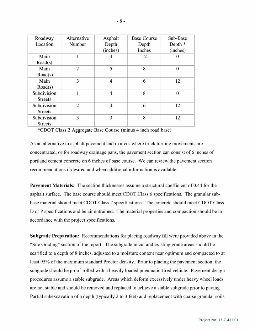
Roadway
Location
Alternative
Number
Asphalt
Depth
(inches)
Base Course
Depth
Inches
Sub-Base
Depth *
(inches)
Main
Road(s)
1 4 12 0
Main
Road(s)
2 5 8 0
Main
Road(s)
3 4 6 12
Subdivision
Streets
1 4 8 0
Subdivision
Streets
2 4 6 12
Subdivision
Streets
3 3 8 12
*CDOT Class 2 Aggregate Base Course (minus 4 inch road base)
As an alternative to asphalt pavement and in areas where truck turning movements are
concentrated, or for roadway drainage pans, the pavement section can consist of 6 inches of
portland cement concrete on 6 inches of base course. We can review the pavement section
recommendations if desired and when additional information is available.
Pavement Materials: The section thicknesses assume a structural coefficient of 0.44 for the
asphalt surface. The base course should meet CDOT Class 6 specifications. The granular sub-
base material should meet CDOT Class 2 specifications. The concrete should meet CDOT Class
D or P specifications and be air entrained. The material properties and compaction should be in
accordance with the project specifications.
Subgrade Preparation: Recommendations for placing roadway fill were provided above in the
“Site Grading” section of the report. The subgrade in cut and existing grade areas should be
scarified to a depth of 8 inches, adjusted to a moisture content near optimum and compacted to at
least 95% of the maximum standard Proctor density. Prior to placing the pavement section, the
subgrade should be proof-rolled with a heavily loaded pneumatic-tired vehicle. Pavement design
procedures assume a stable subgrade. Areas which deform excessively under heavy wheel loads
are not stable and should be removed and replaced to achieve a stable subgrade prior to paving.
Partial subexcavation of a depth (typically 2 to 3 feet) and replacement with coarse granular soils
- 9 -
Project No. 17-7-431.01
and/or Tensar TX-140 or TX-160 geo-grid may be needed in existing fill areas and should be
further evaluated at the time of construction.
Drainage: The collection and diversion of surface drainage away from paved areas is extremely
important to the satisfactory performance of pavement. Drainage design should provide for the
removal of water from paved areas and prevent wetting of the subgrade soils. Uphill roadside
ditches should have an invert level at least 1 foot below the road base and sub-base, or be a
minimum 1 foot depth with a minimum 12 inch thick clay soil cover over the roadside ditch
slope. We should review the ditch detail if a clay soil cover over the base course and sub-base is
planned.
PRELIMINARY FOUNDATION RECOMMENDATIONS
Provided below is a discussion of preliminary recommendations for building foundation, floor
slab and, subsurface and surface drainage for the residences and club house. Site specific studies
should be conducted to provide more detailed design recommendations for the individual
buildings.
FOUNDATIONS
Spread Footings: Bearing conditions will vary depending on the specific location of the
building on the property. Based on the nature of the proposed construction, spread footings
bearing on the natural subsoils or bedrock should be suitable at most of the Phase I residential
building sites and probably the club house. The soils and bedrock have variable compressibility/
expansion potential which could result in differential movement of the foundation especially in
areas where the footings transition soil to bedrock and/or the bearing materials become wetted.
We expect the footings can be sized for an allowable bearing pressure in the range of 1,000 psf
to 1,500 psf for the neutral soils and 2,000 psf to 3,000 psf for the bedrock. Expansive clays and
bedrock encountered in building areas may need to be removed or the footings designed to
impose a minimum dead load pressure to limit potential heave. Foundation walls should be
designed to span local anomalies and to resist lateral earth loadings when acting as retaining
structures. Below grade areas and retaining walls should be protected from wetting and
- 10 -
Project No. 17-7-431.01
hydrostatic loading by use of an underdrain system. The footings should have a minimum depth
of 42 inches for frost protection.
Deep Foundations: Several options are feasible for a relatively deep foundation system at the
site. Helical piers should be feasible to support the light residential buildings in areas where soil
is deeper than about 12 to 15 feet. Light duty helical piers typically develop a downward
working capacities in the range of 20 to 25 kips. The piers should have a minimum embedded
length of about 15 feet.
In areas where bedrock is shallow, helical piers are not considered feasible due to assumed
shallow refusal and micro-piles would be more desirable. Micro-piles should develop downward
working capacities in the range of 30 to 50 kips depending on the bedrock conditions and their
installation depth. Micro-piles are typically design/build by qualified contractors with
experience in the area. Straight-Shaft drilled piers may also be feasible in most areas of the site
where underlain by bedrock.
In the commercial development area, steel H-piles, heavy duty screw piles or possibly concrete
filled pipe piles driven to refusal in the underlying coarse granular soils are feasible as a
relatively deep foundation system. The piles should develop their structural capacity when
properly installed to refusal.
FLOOR SLABS
Slab-on-grade construction should be feasible for bearing on the natural soils or the weathered
bedrock for subgrade with low or no potential for movement. There could be some post
construction slab movement at sites with collapsible matrix or expansive clays especially if the
subgrade becomes wetted. In areas where gypsum or moisture sensitive soils are exposed at slab
subgrade, it may be necessary to sub-excavate a few feet and replace the material with
compacted structural fill such as road base. To reduce the effects of some differential
movement, floor slabs should be separated from all bearing walls and columns with expansion
joints. Floor slab control joints should be used to reduce damage due to shrinkage cracking. A
minimum 4-inch-thick layer of free-draining gravel should underlie basement level slabs to
facilitate drainage.
- 11 -
Project No. 17-7-431.01
UNDERDRAIN SYSTEM
Although free water was not encountered in the exploratory borings, it has been our experience
in the area where clayey soils are present and/or bedrock is shallows that local perched
groundwater can develop during times of heavy precipitation or seasonal runoff. An underdrain
system should be provided to protect below-grade construction, such as retaining walls,
crawlspace and basement areas from wetting and hydrostatic pressure buildup. The drains
should consist of drainpipe surrounded above the invert level with free-draining granular
material. The drain should be placed at each level of excavation and at least 1 foot below lowest
adjacent finish grade and sloped at a minimum 1% to a suitable gravity outlet. An impervious
membrane such as 20 or 30 mil PVC should typically be placed beneath the drain gravel in a
trough shape and attached to the foundation wall with mastic to prevent wetting of the bearing
soils or bedrock.
SURFACE DRAINAGE
The grading plan for the subdivision should consider runoff from uphill slopes through the
project and at individual sites. Water should not be allowed to pond which could impact slope
stability, pavements and foundations. To limit infiltration into the bearing soils next to
buildings, exterior backfill should be well compacted and have a positive slope away from the
building for a distance of at least 10 feet. Roof downspouts and drains should discharge well
beyond the limits of all backfill and landscape irrigation should be restricted.
LIMITATIONS
This study has been conducted in accordance with generally accepted geotechnical engineering
principles and practices in this area at this time. We make no warranty either express or implied.
The conclusions and recommendations submitted in this report are based upon the data obtained
from the exploratory borings drilled at the locations indicated on Figures 1 and 1A, the proposed
type of construction and our experience in the area. Our services do not include determining the
presence, prevention or possibility of mold or other biological contaminants (MOBC) developing
in the future. If the client is concerned about MOBC, then a professional in this special field of
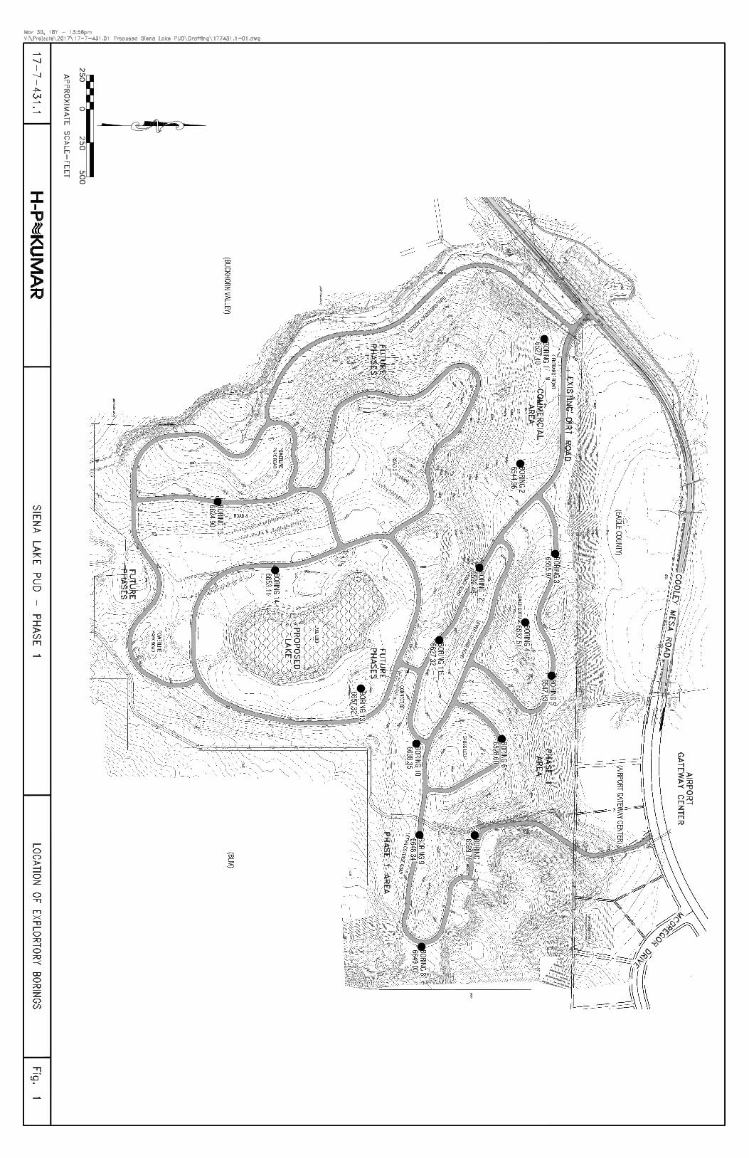
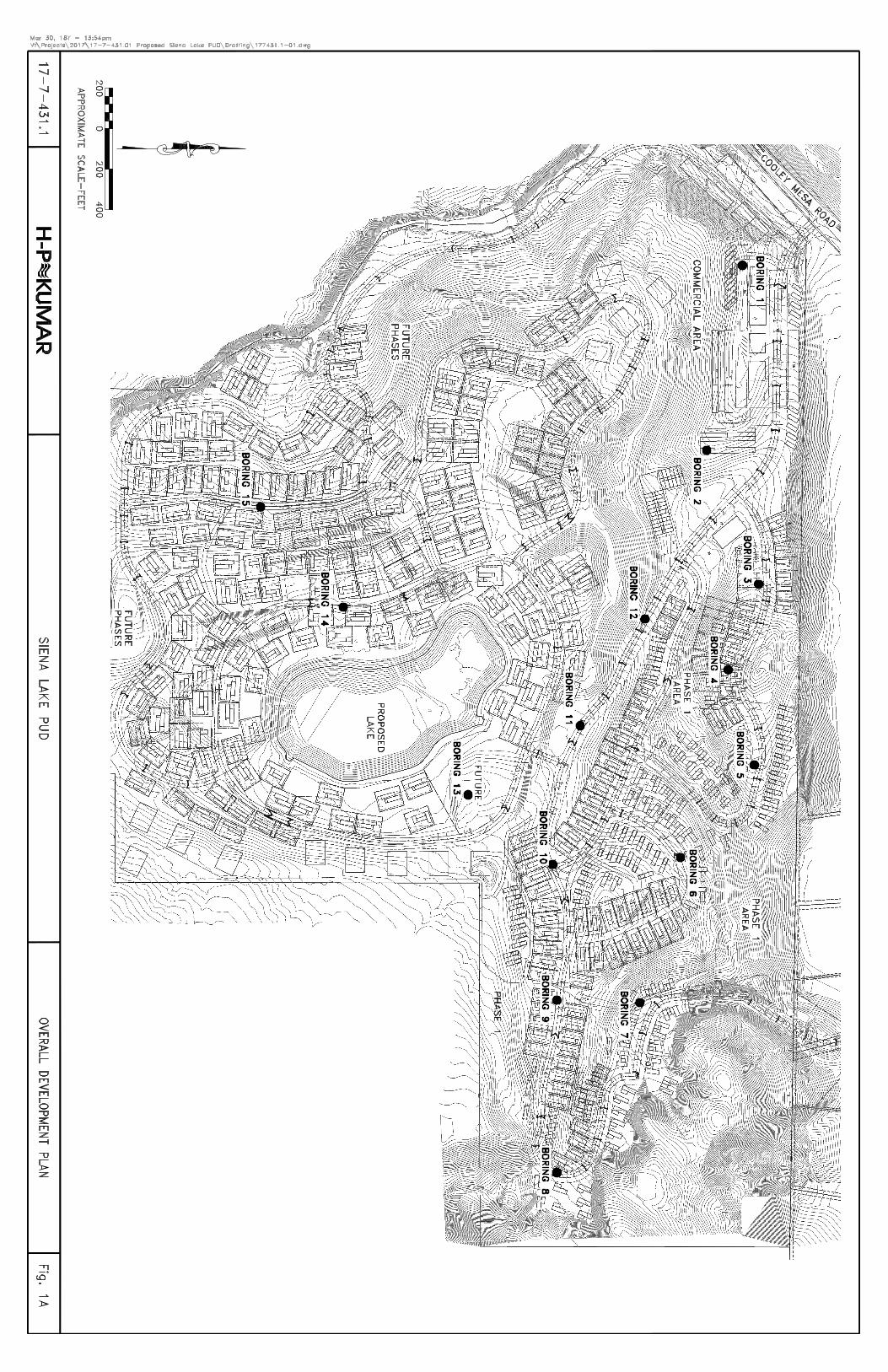
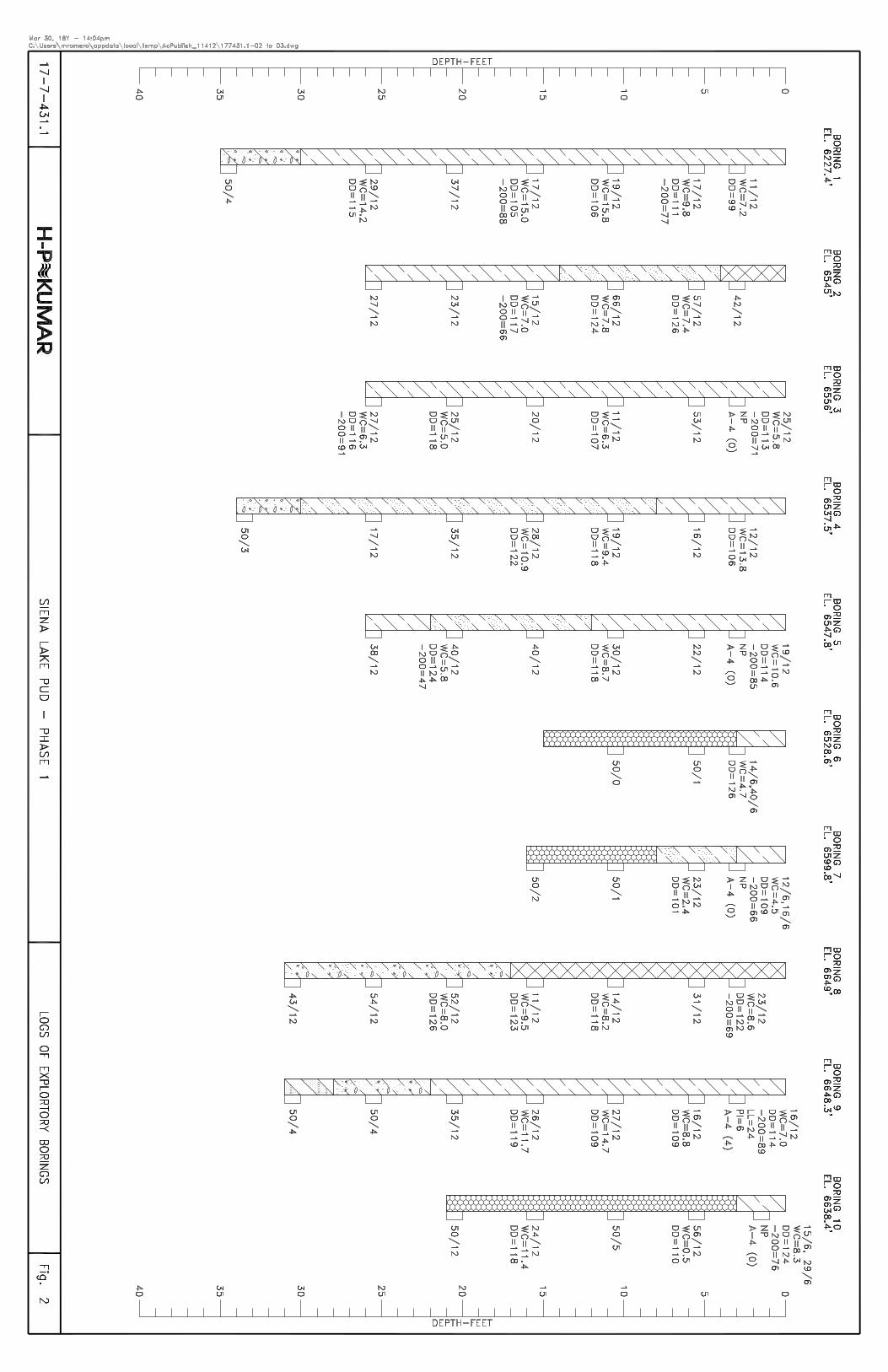
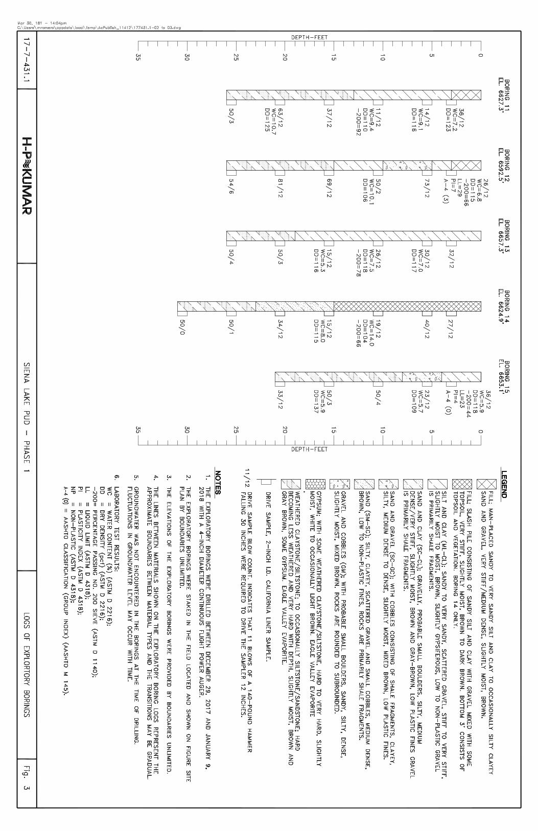
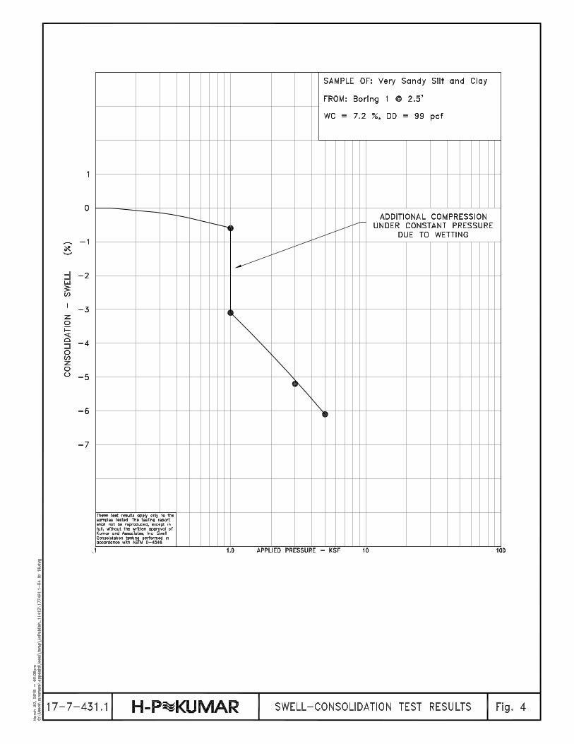
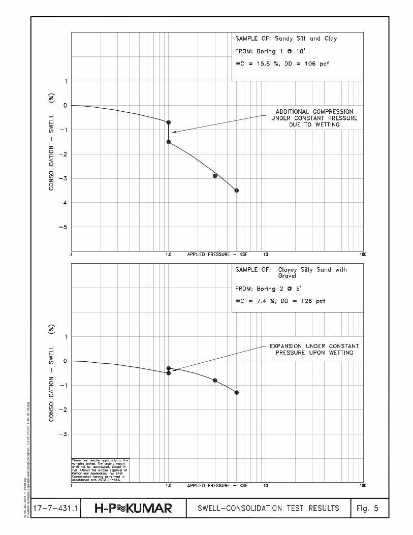

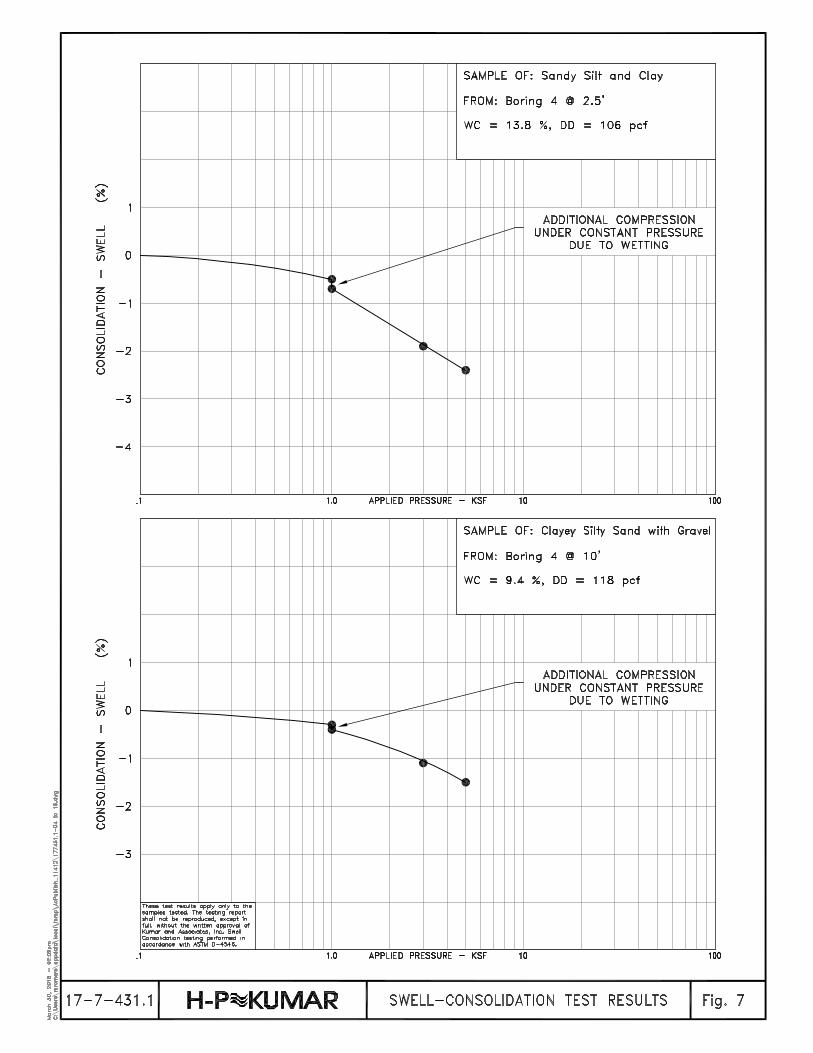
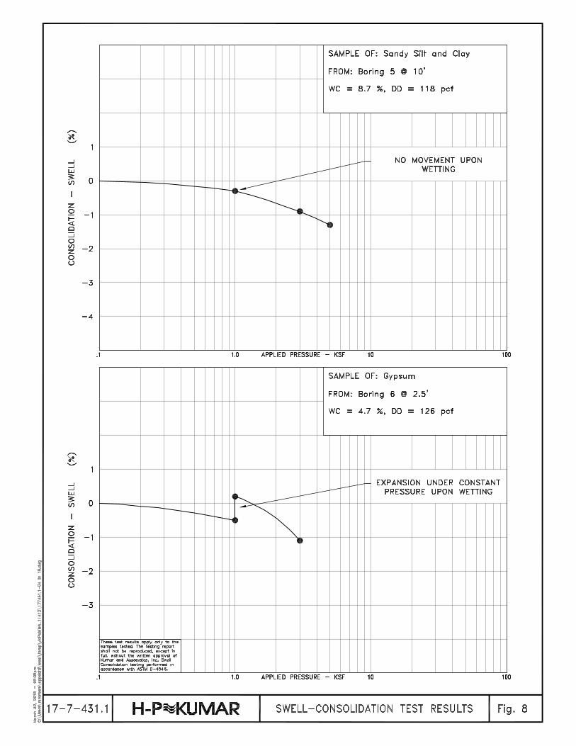
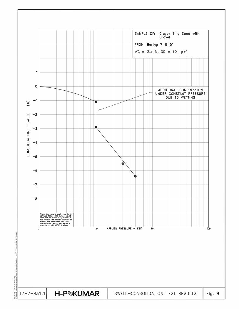
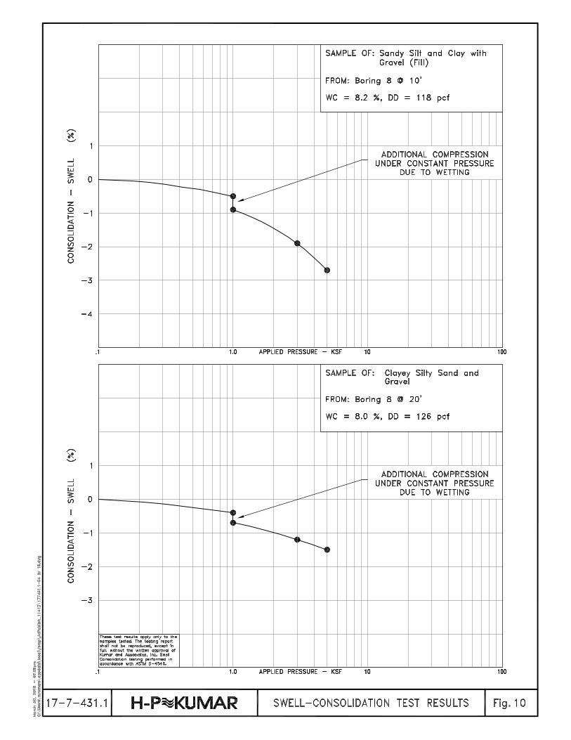
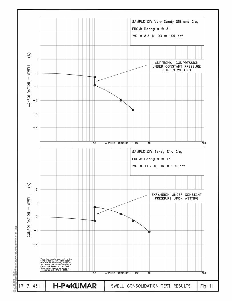
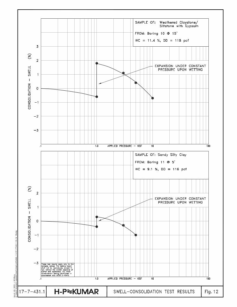
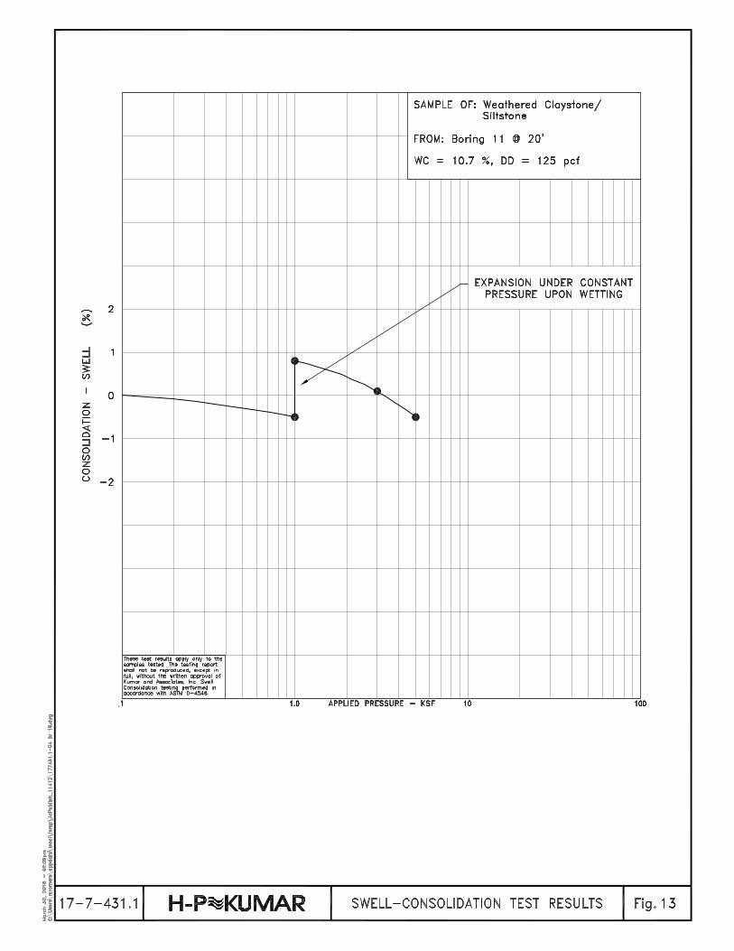
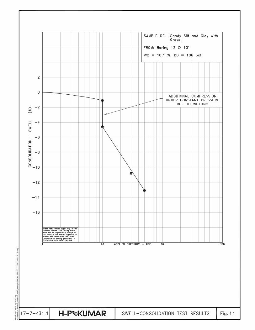


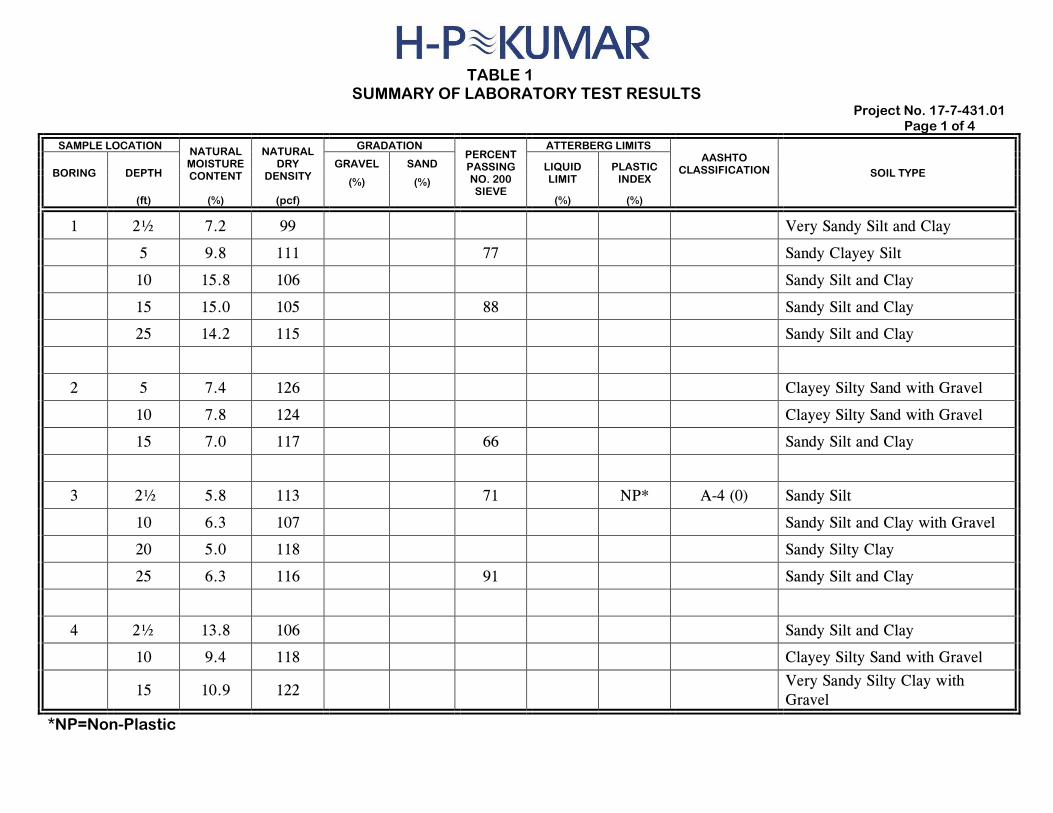
TABLE 1 SUMMARY OF LABORATORY TEST RESULTS
Project No. 17-7-431.01 Page 1 of 4
SAMPLE LOCATION NATURAL MOISTURE CONTENT
NATURAL DRY
DENSITY
GRADATION PERCENT PASSING NO. 200 SIEVE
ATTERBERG LIMITS AASHTO
CLASSIFICATION SOIL TYPE BORING DEPTH GRAVEL SAND LIQUID
LIMIT PLASTIC
INDEX (%) (%)
(ft) (%) (pcf) (%) (%)
1 2½ 7.2 99 Very Sandy Silt and Clay
5 9.8 111 77 Sandy Clayey Silt
10 15.8 106 Sandy Silt and Clay
15 15.0 105 88 Sandy Silt and Clay
25 14.2 115 Sandy Silt and Clay
2 5 7.4 126 Clayey Silty Sand with Gravel
10 7.8 124 Clayey Silty Sand with Gravel
15 7.0 117 66 Sandy Silt and Clay
3 2½ 5.8 113 71 NP* A-4 (0) Sandy Silt
10 6.3 107 Sandy Silt and Clay with Gravel
20 5.0 118 Sandy Silty Clay
25 6.3 116 91 Sandy Silt and Clay
4 2½ 13.8 106 Sandy Silt and Clay
10 9.4 118 Clayey Silty Sand with Gravel
15 10.9 122 Very Sandy Silty Clay with
Gravel
*NP=Non-Plastic
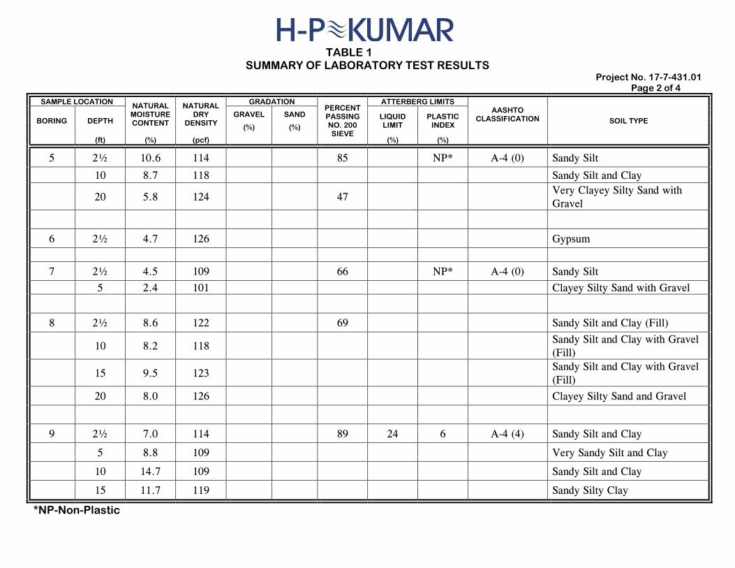
TABLE 1
SUMMARY OF LABORATORY TEST RESULTS Project No. 17-7-431.01
Page 2 of 4
SAMPLE LOCATION NATURAL MOISTURE CONTENT
NATURAL DRY
DENSITY
GRADATION PERCENT PASSING NO. 200 SIEVE
ATTERBERG LIMITS AASHTO
CLASSIFICATION SOIL TYPE BORING DEPTH GRAVEL SAND LIQUID
LIMIT PLASTIC
INDEX (%) (%)
(ft) (%) (pcf) (%) (%)
5 2½ 10.6 114 85 NP* A-4 (0) Sandy Silt
10 8.7 118 Sandy Silt and Clay
20 5.8 124 47 Very Clayey Silty Sand with
Gravel
6 2½ 4.7 126 Gypsum
7 2½ 4.5 109 66 NP* A-4 (0) Sandy Silt
5 2.4 101 Clayey Silty Sand with Gravel
8 2½ 8.6 122 69 Sandy Silt and Clay (Fill)
10 8.2 118 Sandy Silt and Clay with Gravel
(Fill)
15 9.5 123 Sandy Silt and Clay with Gravel
(Fill)
20 8.0 126 Clayey Silty Sand and Gravel
9 2½ 7.0 114 89 24 6 A-4 (4) Sandy Silt and Clay
5 8.8 109 Very Sandy Silt and Clay
10 14.7 109 Sandy Silt and Clay
15 11.7 119 Sandy Silty Clay
*NP-Non-Plastic
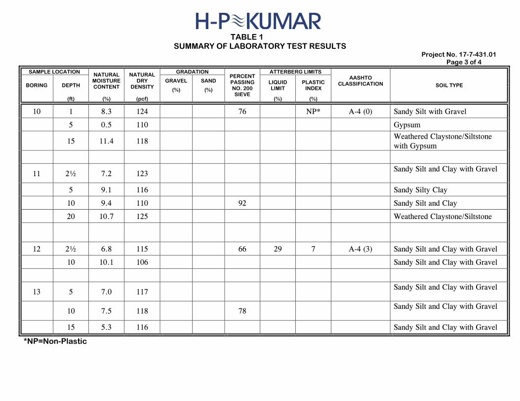
TABLE 1
SUMMARY OF LABORATORY TEST RESULTS Project No. 17-7-431.01
Page 3 of 4
SAMPLE LOCATION NATURAL MOISTURE CONTENT
NATURAL DRY
DENSITY
GRADATION PERCENT PASSING NO. 200 SIEVE
ATTERBERG LIMITS AASHTO
CLASSIFICATION SOIL TYPE BORING DEPTH GRAVEL SAND LIQUID
LIMIT PLASTIC
INDEX (%) (%)
(ft) (%) (pcf) (%) (%)
10 1 8.3 124 76 NP* A-4 (0) Sandy Silt with Gravel
5 0.5 110 Gypsum
15 11.4 118 Weathered Claystone/Siltstone
with Gypsum
11 2½ 7.2 123 Sandy Silt and Clay with Gravel
5 9.1 116 Sandy Silty Clay
10 9.4 110 92 Sandy Silt and Clay
20 10.7 125 Weathered Claystone/Siltstone
12 2½ 6.8 115 66 29 7 A-4 (3) Sandy Silt and Clay with Gravel
10 10.1 106 Sandy Silt and Clay with Gravel
13 5 7.0 117 Sandy Silt and Clay with Gravel
10 7.5 118 78 Sandy Silt and Clay with Gravel
15 5.3 116 Sandy Silt and Clay with Gravel
*NP=Non-Plastic
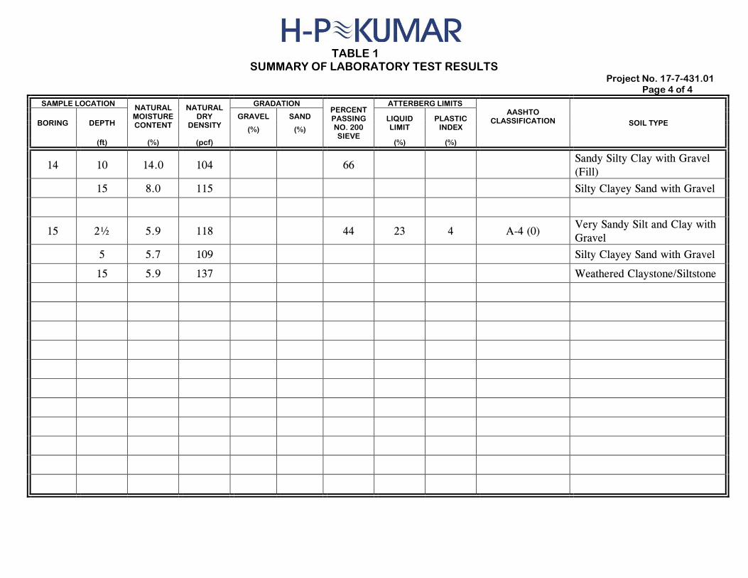
TABLE 1
SUMMARY OF LABORATORY TEST RESULTS Project No. 17-7-431.01
Page 4 of 4
SAMPLE LOCATION NATURAL MOISTURE CONTENT
NATURAL DRY
DENSITY
GRADATION PERCENT PASSING NO. 200 SIEVE
ATTERBERG LIMITS AASHTO
CLASSIFICATION SOIL TYPE BORING DEPTH GRAVEL SAND LIQUID
LIMIT PLASTIC
INDEX (%) (%)
(ft) (%) (pcf) (%) (%)
14 10 14.0 104 66 Sandy Silty Clay with Gravel
(Fill)
15 8.0 115 Silty Clayey Sand with Gravel
15 2½ 5.9 118 44 23 4 A-4 (0) Very Sandy Silt and Clay with
Gravel
5 5.7 109 Silty Clayey Sand with Gravel
15 5.9 137 Weathered Claystone/Siltstone


![j ^bbjmjZeghf - infotim.rs · GZhkgh\mqeZgZ DklZ\ AZdhgZhih hijb\j_^bbjmjZeghf jZa\h m ÄKem`[_gb]eZkgbdJK´ [j - ^j aZdhgb FbgbklZjih hijb\j_^_ , rmfZjkl\Zb\h^hijb\j_^_^hghkb](https://img.pdfslide.us/doc/110x75/5e84c2754e86cb3c3b368b4b/j-bbjmjzeghf-gzhkghmqezgz-dklz-azdhgzhih-hijbjbbjmjzeghf-jzah-m-kemgbezkgbdjk.jpg)