Embed Size (px)
Citation preview

SP-1 UserManual
MVTM V Technology Ltd.
_______________________________________________________________________________________________________
_______________________________________________________________________________________________________Doc 5000-0032-02 Page ii
S P - 1 S O L D E R P A S T E I N S P E C T I O N S Y S T E M
SP-1 User ManualRevision 2.0October 1998
Document No. 5000-0032
MV Technology Ltd.Unit 24 IDA Enterprise Centre, Pearse Street, Dublin 2, Ireland
Phone 353-1-6718177 • Fax 353-1-6718470Email: [email protected] Home Page: http://www.mvt.ie
All rights reserved. No part of this document may be stored in a retrieval system,transmitted, or used in any form or by any means, electronic, mechanical, photocopying,
recording or otherwise without the prior permission of the copyright holder.MV Technology Ltd. retains the right to modify this document without notice.
_______________________________________________________________________________________________________
_______________________________________________________________________________________________________Doc 5000-0032-02 Page iii
Contents
SP-1 Introduction____________________________________________________ 1
1.1 SP-1 Operation_____________________________________________________ 2
1.2 SP-1 Functional Components _________________________________________ 4
SP-1 Safety Features _________________________________________________ 5
2.1 Electrical Safety ____________________________________________________ 6
Laser Safety____________________________________________________________ 9
2.3 Protective Guards __________________________________________________ 9
2.4 Safety Warnings___________________________________________________ 10
SP-1 Inspection Cycle _______________________________________________ 11
3.1 How to Start Up/Login. _____________________________________________ 13
3.2 The Main User Menu_______________________________________________ 14
3.3 The 3 Operator Access Levels________________________________________ 15
3.4 Pass Thru / Remote Inspection Mode _________________________________ 16
3.5 Setting PCB Type__________________________________________________ 17
3.6 Set 2D/3D Inspection Mode__________________________________________ 18
3.7 Inspection Cycle ___________________________________________________ 18
3.8 Fiducial Fail Menu_________________________________________________ 19
3.9 2D Action on Failure Menu _________________________________________ 20
3.10 3D Action on Failure Menu ________________________________________ 24
3.11 Shutdown _______________________________________________________ 27
Programming a Board _______________________________________________ 28
4.1 CAD Conversion __________________________________________________ 30
4.2 Putting the System into Soft Stop_____________________________________ 31
4.3 Setting Fiducial Position ____________________________________________ 32
4.4 Editing Fiducial Parameters _________________________________________ 34
4.5 2D Board Programming ____________________________________________ 39
4.6 Editing 2D Parameters & Thresholds _________________________________ 39
4.7 3D Mode Programming_____________________________________________ 46
4.8 3D Scan Selection (F5 from Solder Paste Menu) ________________________ 47
4.9 Running a 3D Local Inspection ______________________________________ 48
4.10 3D Action on Failure ______________________________________________ 49
4.11 Running a GR&R Test ____________________________________________ 52
SP-1 Advanced Features _____________________________________________ 53
5.1 Commands while running an Inspection _______________________________ 54

_______________________________________________________________________________________________________
_______________________________________________________________________________________________________Doc 5000-0032-02 Page iv
5.2 Releasing boards before an inspection is finished________________________ 54
5.3 The Config.txt File _________________________________________________ 54
5.4 Report File Formats________________________________________________ 59
5.5 Changing Operator 2 & 3 Passwords__________________________________ 60
5.6 Setting XY Table Software Limits ____________________________________ 60
5.7 Viewing Saved Images ______________________________________________ 60
5.8 Loading New Software to 3D Imaging Head____________________________ 61
5.9 Loading New SP-1 Executable Software _______________________________ 62
5.10 Rotating Board Files ______________________________________________ 62
5.11 Deleting, Copying & Renaming Board Files___________________________ 63
5.12 Setting Window Sizes _____________________________________________ 63
5.13 Setting Camera Border ____________________________________________ 64
_______________________________________________________________________________________________________
_______________________________________________________________________________________________________Doc 5000-0032-02 Page v
Revision History
Revision Nature of Change Author Date1.0 First release B. Hanley June
19982.0 Revised for 1.02 & 1.03 Software –
rearranged Programming SectionP. Browner &M. Williams
Nov.1998
© MVT SP-1 USER MANUAL SP-1 INTRODUCTION
5000-0032-02 1
Chapter1
SP-1 Introduction
CHAPTER CONTENTS1.1 SP-1 Operation_______________________________________________ 2
1.2 SP-1 Functional Components ___________________________________ 4
SUMMARYThis chapter gives a general Introduction to the SP-1. It outlines what thesystem does, what it measures, its key characteristics, and its functionalcomponents. These functions will be explained in greater detail in laterchapters.
SP-1 Introduction
© MVT SP-1 USER MANUAL SP-1 INTRODUCTION_____________________________________________________________________
_______________________________________________________________________________________________________Doc 5000-0032-02 Page 2
1.1 SP-1 OperationWhat is the SP-1?
The SP-1 is an in-line solder paste inspection system designed for SMT manufacturing. It
provides 100% 2D and sampled 3D coverage. The SP-1 performs highly accurate and
repeatable measurements of stencil offset and skew as well as solder paste area, height and
volume.
What does the SP-1 offer?
n 100% 2D inspection of all boards at production rates.
n Immediate detection of solder paste defects.
n High accuracy, even with fine pitch and BGAs.
n Statistical process control tools.
n Ease of use and programming.
Why use the SP-1?
The Problem
Over 50% of all component defects encountered are caused by problems during solder
paste printing. This includes all types of solder defects such as bridging, tombstoning,
billboarding or open joints. Understanding how these defects correlate to the numerous
variables in the printing process is a problem faced by all SMT manufacturers.
The MVT Solution
The way to achieve a controlled process is to perform 100% inspection at the earliest
possible stage. In the case of solder paste printing that means directly after the printing
process. In an Industry first, MVT offers a solution that combines the complete coverage
and speed of a 2D system with the critical data gained from 3D measurements. It also
incorporates powerful statistical process control (SPC) software to characterise the solder
paste printing process.
The 100% 2D inspection detects stencil misalignment and area fill defects caused by
random errors such as blocked apertures, low paste on the stencil, and dry paste.
© MVT SP-1 USER MANUAL SP-1 INTRODUCTION_____________________________________________________________________
_______________________________________________________________________________________________________Doc 5000-0032-02 Page 3
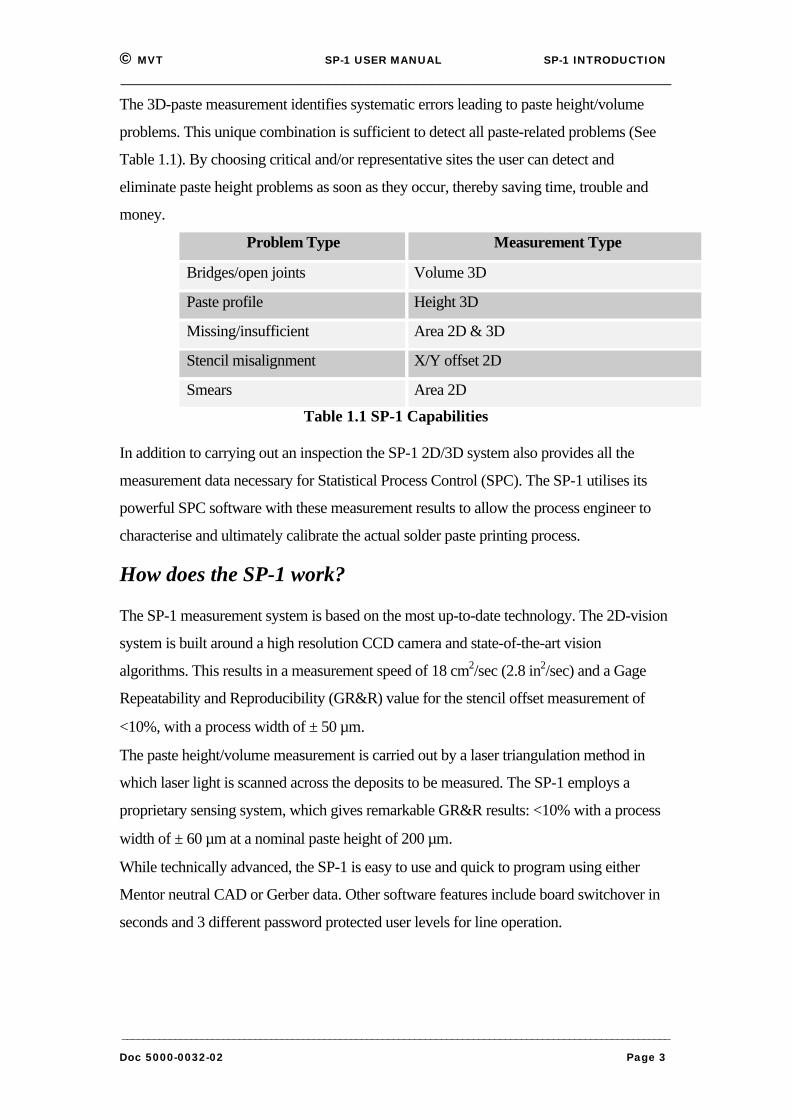
The 3D-paste measurement identifies systematic errors leading to paste height/volume
problems. This unique combination is sufficient to detect all paste-related problems (See
Table 1.1). By choosing critical and/or representative sites the user can detect and
eliminate paste height problems as soon as they occur, thereby saving time, trouble and
money.
Problem Type Measurement Type
Bridges/open joints Volume 3D
Paste profile Height 3D
Missing/insufficient Area 2D & 3D
Stencil misalignment X/Y offset 2D
Smears Area 2D
Table 1.1 SP-1 Capabilities
In addition to carrying out an inspection the SP-1 2D/3D system also provides all the
measurement data necessary for Statistical Process Control (SPC). The SP-1 utilises its
powerful SPC software with these measurement results to allow the process engineer to
characterise and ultimately calibrate the actual solder paste printing process.
How does the SP-1 work?
The SP-1 measurement system is based on the most up-to-date technology. The 2D-vision
system is built around a high resolution CCD camera and state-of-the-art vision
algorithms. This results in a measurement speed of 18 cm2/sec (2.8 in2/sec) and a Gage
Repeatability and Reproducibility (GR&R) value for the stencil offset measurement of
<10%, with a process width of ± 50 µm.
The paste height/volume measurement is carried out by a laser triangulation method in
which laser light is scanned across the deposits to be measured. The SP-1 employs a
proprietary sensing system, which gives remarkable GR&R results: <10% with a process
width of ± 60 µm at a nominal paste height of 200 µm.
While technically advanced, the SP-1 is easy to use and quick to program using either
Mentor neutral CAD or Gerber data. Other software features include board switchover in
seconds and 3 different password protected user levels for line operation.
© MVT SP-1 USER MANUAL SP-1 INTRODUCTION_____________________________________________________________________
_______________________________________________________________________________________________________Doc 5000-0032-02 Page 4
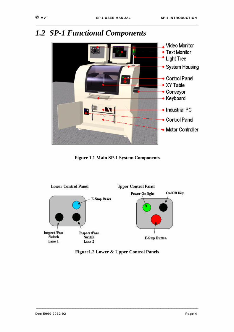
1.2 SP-1 Functional Components
Figure 1.1 Main SP-1 System Components
Figure1.2 Lower & Upper Control Panels

© MVT SP-1 USER MANUAL SP-1 SAFETY FEATURES___________________________________________________________________
_______________________________________________________________________________________________________Doc 5000-0032-02 Page 5
Chapter2
SP-1 Safety Features
CHAPTER CONTENTS2.1 Electrical Safety ______________________________________________ 6
2.2 Laser Safety _________________________________________________ 9
2.3 Protective Guards_____________________________________________ 9
2.4 Safety Warnings_____________________________________________ 10
SUMMARYThis chapter describes the various safety features that are incorporated intothe machine to provide a safe environment for the operator. The machine isdesigned so that during the course of normal operation the user is neverrequired to work in, or have exposure to areas where they could cause harmto themselves or others.
SP-1 Safety
Features

© MVT SP-1 USER MANUAL SP-1 SAFETY FEATURES___________________________________________________________________
_______________________________________________________________________________________________________Doc 5000-0032-02 Page 6
2.1 Electrical Safety
Electrical Enclosure
All live power and control circuits are installed into an enclosure to reduce the risk of
direct contact with live parts (as defined in 60204-1:1992, 6.2.1 a & b). This is positioned
to the rear of the machine.
The main electrical enclosure provides further protection by interlocking the access door to
the enclosure with the safety circuit. The enclosure door will not open until the
interlocking device is activated.
Activation of the lockable interlocking device removes power from all of the internal
circuitry except the primary side of the mains contactor. This is clearly labeled and
protected by a non-conducting cover.
The Low voltage control gear in the pneumatics panel is also protected in an enclosure
behind a labeled ‘Fixed Guard’. ‘Fixed Guards’ protect all other low voltage circuits.
NEVER REMOVE THE FIXED GUARDS !
WARNING: LETHAL VOLTAGE
DANGEROUS VOLTAGES EXIST INTHIS EQUIPMENT. ENSURE THAT ALL
ELECTRICAL ENCLOSURE COVERSARE FITTED AND INTACT BEFORE
OPERATING THE EQUIPMENT.

© MVT SP-1 USER MANUAL SP-1 SAFETY FEATURES___________________________________________________________________
_______________________________________________________________________________________________________Doc 5000-0032-02 Page 7
Figure 2.1 Machine Layout
Emergency Stop Loop
The Emergency Stop (or E-Stop) connects selected modules in the machine and shuts
down powered mechanisms that may cause harm to the operator, during emergency
situations.
The E-Stop of this machine is clearly visible and identifiable. It is at the front right hand
side of the machine and is activated by pushing down on it once. (See Figure 2.1).
Raising the front hood door has the same effect as pressing the E-Stop, however it is
recommended that the E-Stop button be pushed before the front hood door is opened.
This machine has many modes of operation. Each mode is overridden by the E-Stop and
all modes have the same safety requirements.
The E-Stop on this machine is designed to meet the harmonised European standard for
safety of machinery - electrical equipment EN 60204-1.
This machine can only be started or restarted by the user with the start-up devices
provided. It is important to use the correct Power Up Sequence.
Power Up Sequence to restore from ‘E-Stop’
1. Pull out the E-Stop button until it stays up.
2. Press the E-Stop reset switch as shown in the diagram on previous page.

© MVT SP-1 USER MANUAL SP-1 SAFETY FEATURES___________________________________________________________________
_______________________________________________________________________________________________________Doc 5000-0032-02 Page 8
Power Up Sequence from ‘Mains Off’ Situation
1. Turn the ‘Mains Isolator’ to the ‘ON’ position when the rear access
doors are locked.
2. Ensure that the X-Y table is free to move over its entire range before
continuing. Remove any tools or equipment that may hinder table
movement.
3. Ensure that the top frame window is closed and the E-stop is depressed.
4. Turn the key switch at the front of the machine to the ‘ON’ position if
not already in this position. The green light will come on at the front
panel.
5. Turn on the power supply unit for the lighting head and ensure the
setting is on ‘High’.
6. Ensure the ‘Pass Through’ switch is in the correct position.
7. Turn on the motor controller unit at the on switch.
8. Turn on the video and text monitors.
9. Release the ‘Emergency Stop’ push button by pulling it up.
10. Depress the emergency stop ‘Reset’ button (See Figure 2.1).
11. Power on the Industrial PC at its ‘ON’ switch and await the ‘Log-on’
prompt. This can take two minutes.
No Uncontrolled motion on restart.
When power supply is removed from the system it is safe. On restoration of supply the
safety relay will not re-close contacts until the power up sequence has been completed.
This ensures that the XY table cannot move without the power being reset.
Earth Bonding
All external metal surfaces are mechanically and electrically bonded to the machine earth
point. The bonding wire used is identified by its green and yellow insulation and is
commonly used to earth bond throughout. Never remove or cut these wires and if you
© MVT SP-1 USER MANUAL SP-1 SAFETY FEATURES___________________________________________________________________
_______________________________________________________________________________________________________Doc 5000-0032-02 Page 9
should find a cut or damaged connection, do not operate the machine and inform a
technician as soon as possible.
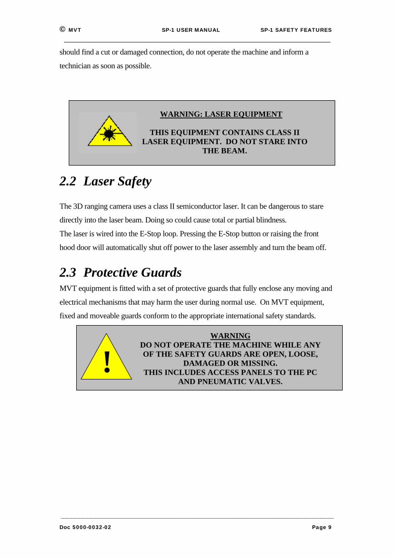
2.2 Laser Safety
The 3D ranging camera uses a class II semiconductor laser. It can be dangerous to stare
directly into the laser beam. Doing so could cause total or partial blindness.
The laser is wired into the E-Stop loop. Pressing the E-Stop button or raising the front
hood door will automatically shut off power to the laser assembly and turn the beam off.
2.3 Protective GuardsMVT equipment is fitted with a set of protective guards that fully enclose any moving and
electrical mechanisms that may harm the user during normal use. On MVT equipment,
fixed and moveable guards conform to the appropriate international safety standards.
WARNINGDO NOT OPERATE THE MACHINE WHILE ANYOF THE SAFETY GUARDS ARE OPEN, LOOSE,
DAMAGED OR MISSING.THIS INCLUDES ACCESS PANELS TO THE PC
AND PNEUMATIC VALVES.!
WARNING: LASER EQUIPMENT
THIS EQUIPMENT CONTAINS CLASS IILASER EQUIPMENT. DO NOT STARE INTO
THE BEAM.
© MVT SP-1 USER MANUAL SP-1 SAFETY FEATURES___________________________________________________________________
_______________________________________________________________________________________________________Doc 5000-0032-02 Page 10
2.4 Safety WarningsSafety Devices
The safety features designed into this machine are for the protection of everyone.
MVT STRONGLY RECOMMENDS SAFETY DEVICES ANDINTERLOCKS ARE NEVER OVERRIDDEN.
Conveyor safety
Do not put hands on conveyor when it is running. It could cause friction burns and your
hand could get caught between the conveyors of adjoining machines.
X-Y Gantry
The X-Y table is a solid metal assembly and can move at up to 1.5 m/s. This could cause
severe impact or crush injury. The Protective Guards are designed to prevent access to
areas where this potential injury may occur.
DO NOT OPERATE THE MACHINE WHILE ANY OF THESAFETY GUARDS ARE OPEN, LOOSE, DAMAGED OR MISSING.
Stability
This machine weighs approx. 1,500 kg, and has a low center of gravity.
DO NOT ATTEMPT TO LIFT OR TIP THE MACHINE AT EITHEREND OR SIDE, AS YOU WILL DAMAGE BOTH THE MACHINE
AND YOUR BACK.DON’T EVEN DO IT WITH THE HELP OF OTHERS!
Lethal Voltages
Dangerous voltages exist in areas of this machine.
ENSURE THAT ALL ELECTRICAL ENCLOSURE COVERS AREFITTED AND INTACT BEFORE OPERATING THE EQUIPMENT.
Falling Objects
Ensure that the monitor(s) are secure on top of the hood so that there is no possibility of
them falling during normal use of the machine.
Do not store boards, equipment, stencils etc. on top of the machine.

© MVT SP-1 USER MANUAL BOARD INSPECTION_____________________________________________________________________
_______________________________________________________________________________________________________Doc 5000-0032-02 Page 11
Chapter3
SP-1 Inspection Cycle
CHAPTER CONTENTS3.1 How to Start Up/Login. _______________________________________ 13
3.2 The Main User Menu ________________________________________ 14
3.3 The 3 Operator Access Levels __________________________________ 15
3.4 Pass Thru / Remote Inspection Mode ____________________________ 16
3.5 Setting PCB Type ____________________________________________ 17
Adjusting Conveyor Rail Width _______________________________ 17
3.6 Set 2D/3D Inspection Mode____________________________________ 18
3D Skip Factor______________________________________________ 18
3.7 Inspection Cycle_____________________________________________ 18
3.8 Fiducial Fail Menu __________________________________________ 19
3.9 2D Action on Failure Menu ___________________________________ 20
Typical 2D component errors__________________________________ 22
2D Graphics monitor display __________________________________ 23
Marking False Fails – 2D _____________________________________ 23
Omitting Parts – 2D _________________________________________ 23
Saving Images – 2D __________________________________________ 23
Skipping Parts – 2D__________________________________________ 23
3.10 3D Action on Failure Menu ___________________________________ 24
3D Action on Failure Menu Commands _________________________ 25
Interpreting the Graphics Monitor Display for 3D Action on Failure_ 26
3.11 Shutdown __________________________________________________ 27
Inspecting a Board
© MVT SP-1 USER MANUAL BOARD INSPECTION_____________________________________________________________________
_______________________________________________________________________________________________________Doc 5000-0032-02 Page 12
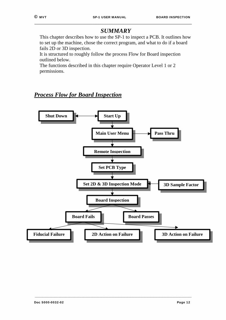
SUMMARYThis chapter describes how to use the SP-1 to inspect a PCB. It outlines howto set up the machine, chose the correct program, and what to do if a boardfails 2D or 3D inspection.It is structured to roughly follow the process Flow for Board inspectionoutlined below.The functions described in this chapter require Operator Level 1 or 2permissions.
Process Flow for Board Inspection
Pass Thru
3D Sample Factor
Fiducial Failure 3D Action on Failure
Start Up
Main User Menu
Remote Inspection
Set PCB Type
Set 2D & 3D Inspection Mode
Board Inspection
2D Action on Failure
Board Fails Board Passes
Shut Down

© MVT SP-1 USER MANUAL BOARD INSPECTION_____________________________________________________________________
_______________________________________________________________________________________________________Doc 5000-0032-02 Page 13
3.1 How to Start Up/Login.
1. Ensure the front safety door is closed.
2. Ensure the Emergency Stop button is OFF.
3. Switch the rear system power switch to ON.
4. Switch the front system power key to ON. The green light will come on.
5. Ensure the XY table power is on by checking that LEDs are lit on the Motor
Controller Panel.
6. Switch the computer on. System will take about 2 minutes to boot up.
7. Login to system:
8. login name: cpi
9. password: cpi602
10. Login and Password are case sensitive.
11. Double-Click the SP-1 icon on the Desktop
12. System XY table homes on start-up.
© MVT SP-1 USER MANUAL BOARD INSPECTION_____________________________________________________________________
_______________________________________________________________________________________________________Doc 5000-0032-02 Page 14
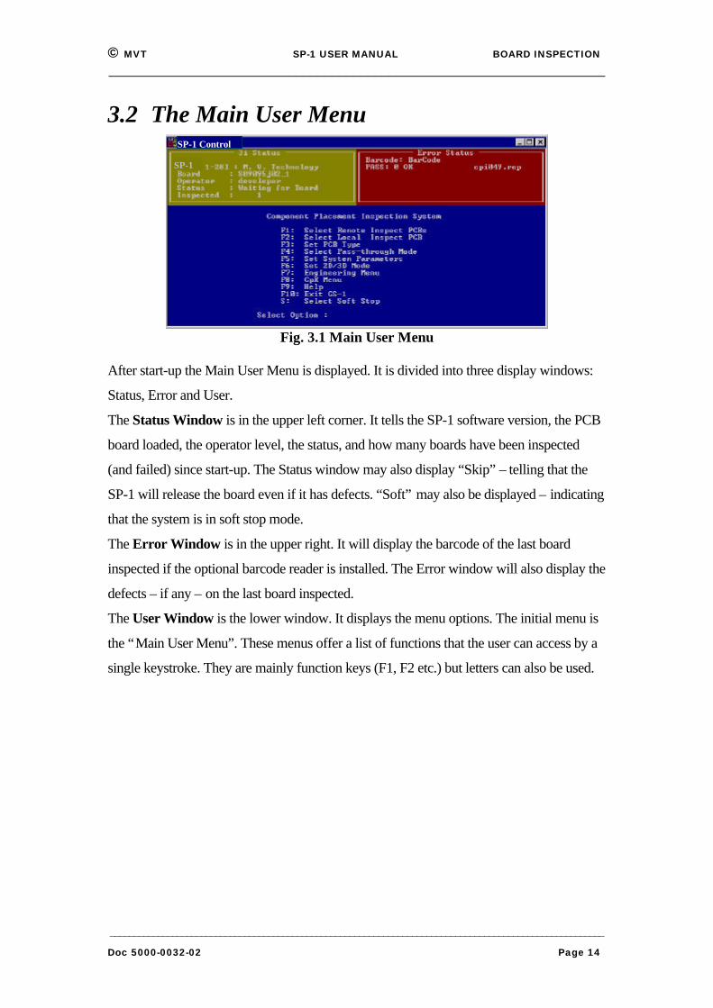
3.2 The Main User MenuSP-1 Control
SP-1
Fig. 3.1 Main User Menu
After start-up the Main User Menu is displayed. It is divided into three display windows:
Status, Error and User.
The Status Window is in the upper left corner. It tells the SP-1 software version, the PCB
board loaded, the operator level, the status, and how many boards have been inspected
(and failed) since start-up. The Status window may also display “Skip” – telling that the
SP-1 will release the board even if it has defects. “Soft” may also be displayed – indicating
that the system is in soft stop mode.
The Error Window is in the upper right. It will display the barcode of the last board
inspected if the optional barcode reader is installed. The Error window will also display the
defects – if any – on the last board inspected.
The User Window is the lower window. It displays the menu options. The initial menu is
the “Main User Menu”. These menus offer a list of functions that the user can access by a
single keystroke. They are mainly function keys (F1, F2 etc.) but letters can also be used.
© MVT SP-1 USER MANUAL BOARD INSPECTION_____________________________________________________________________
_______________________________________________________________________________________________________Doc 5000-0032-02 Page 15
3.3 The 3 Operator Access LevelsThis system is set up with three different user modes: Operator 1, Operator 2 and Operator
3. Each user mode allows different levels of access to the various functions and capabilities
of the system.
In general terms they are:
Operator Level 1:
⇒ Day to day operations. The Inspection Cycle, Remote Inspection and
Action on Failure.
Operator Level 2:
⇒ Operator Level 1 plus more advanced features such as CpK charting, X-Y
table manipulation, and setting fiducial position.
Operator Level 3:
⇒ Operator Level 2 plus all advanced features such as assigning device types
to components and part library management.
Each operator level has a separate, case-sensitive password, which should be secret to
prevent unauthorised use.
The level to which each person is given access will be determined by the level to which
MVT or their company has trained them.

© MVT SP-1 USER MANUAL BOARD INSPECTION_____________________________________________________________________
_______________________________________________________________________________________________________Doc 5000-0032-02 Page 16
3.4 Pass Thru / Remote Inspection Mode
A Pass Thru Mode means that PCBs are passed through the SP-1 but not clamped or
inspected. This mode is provided for Maintenance or when the PCB has not been
programmed for the board being assembled.
q System will go into Pass Thru:
⇒ If power is on, but no login.
⇒ If ‘Inspect/Pass’ switch is switched to Pass Thru (on lower control panel).
⇒ If Pass Thru (F4) option is selected from Main User Menu (requires
Operator 2 or 3 level access).
⇒ If system computer stops communicating with the PLC.
q Going into Remote Inspect (F1) will exit Pass Thru mode.
q System will not run in Pass Thru if power is off or E-stop is pressed.
Note: If E-Stop is pressed, system can be restarted by pressing the Space Bar on the
keyboard (if computer is logged into) or by pressing the E-Stop Reset Switch on
the lower front panel.
© MVT SP-1 USER MANUAL BOARD INSPECTION_____________________________________________________________________
_______________________________________________________________________________________________________Doc 5000-0032-02 Page 17
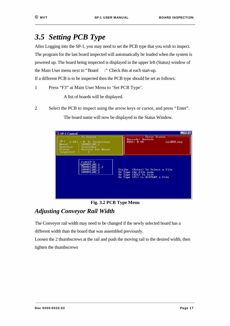
3.5 Setting PCB TypeAfter Logging into the SP-1, you may need to set the PCB type that you wish to inspect.
The program for the last board inspected will automatically be loaded when the system is
powered up. The board being inspected is displayed in the upper left (Status) window of
the Main User menu next to “Board :” Check this at each start-up.
If a different PCB is to be inspected then the PCB type should be set as follows:
1 Press “F3” at Main User Menu to ‘Set PCB Type’.
⇒ A list of boards will be displayed.
2 Select the PCB to inspect using the arrow keys or cursor, and press “Enter”.
⇒ The board name will now be displayed in the Status Window.
SP-1 Control
SP-1
Fig. 3.2 PCB Type Menu
Adjusting Conveyor Rail Width
The Conveyor rail width may need to be changed if the newly selected board has a
different width than the board that was assembled previously.
Loosen the 2 thumbscrews at the rail and push the moving rail to the desired width, then
tighten the thumbscrews

© MVT SP-1 USER MANUAL BOARD INSPECTION_____________________________________________________________________
_______________________________________________________________________________________________________Doc 5000-0032-02 Page 18
3.6 Set 2D/3D Inspection ModeF6 from the Main User Menu enables the user to select the required inspection mode.
The modes are:
1 = 2D Inspection Only
2 = 2D +3D inspection
3 = 3D Inspection Only
3D Skip Factor
If a 3D-inspection option is selected, there is a further option provided to select a 3D-skip
factor (between 1 and 20). If ‘1’ is selected every board will be inspected in 3D.If ‘2’ is
selected only every second PCB will be inspected in 3D and so on.
This does not affect the 2D inspection, which will be performed for every board.
Fig. 3.3 SP-1 Inspection Modes Menu
3.7 Inspection CycleThe SP-1 inspection cycle occurs as follows:
1. As a board enters, the Status window will say:
⇒ “Status: Inspecting Board.”
2. On the Graphics monitor, the system will find the fiducials, then theviews of the deposits being measured.
3. Any defects found will be saved.

© MVT SP-1 USER MANUAL BOARD INSPECTION_____________________________________________________________________
_______________________________________________________________________________________________________Doc 5000-0032-02 Page 19
3.8 Fiducial Fail MenuIf the fiducial measurement fails during an inspection, this window will appear on the
screen with the following options.
Fig. 3.4 SP-1 Fiducial Fail Menu
If the user has Operator Level 1 privileges then select F1 to retry the fiducial inspection. If
this fails then seek assistance from a higher level operator. If one is not available then <F2
: Release Backwards> or <F10 : Release Forwards and Exit> can be selected (this choice
should be dictated by company policy).
If the user has Operator Level 2 privileges then select F3 to set the fiducial position (see
section 4.3). Then press <ESC> and the inspection proceeds.
If the user has Operator Level 3 privileges, press F4 to edit the fiducial parameters (see
section 4.4). Then press <ESC> and the inspection proceeds.
© MVT SP-1 USER MANUAL BOARD INSPECTION_____________________________________________________________________
_______________________________________________________________________________________________________Doc 5000-0032-02 Page 20
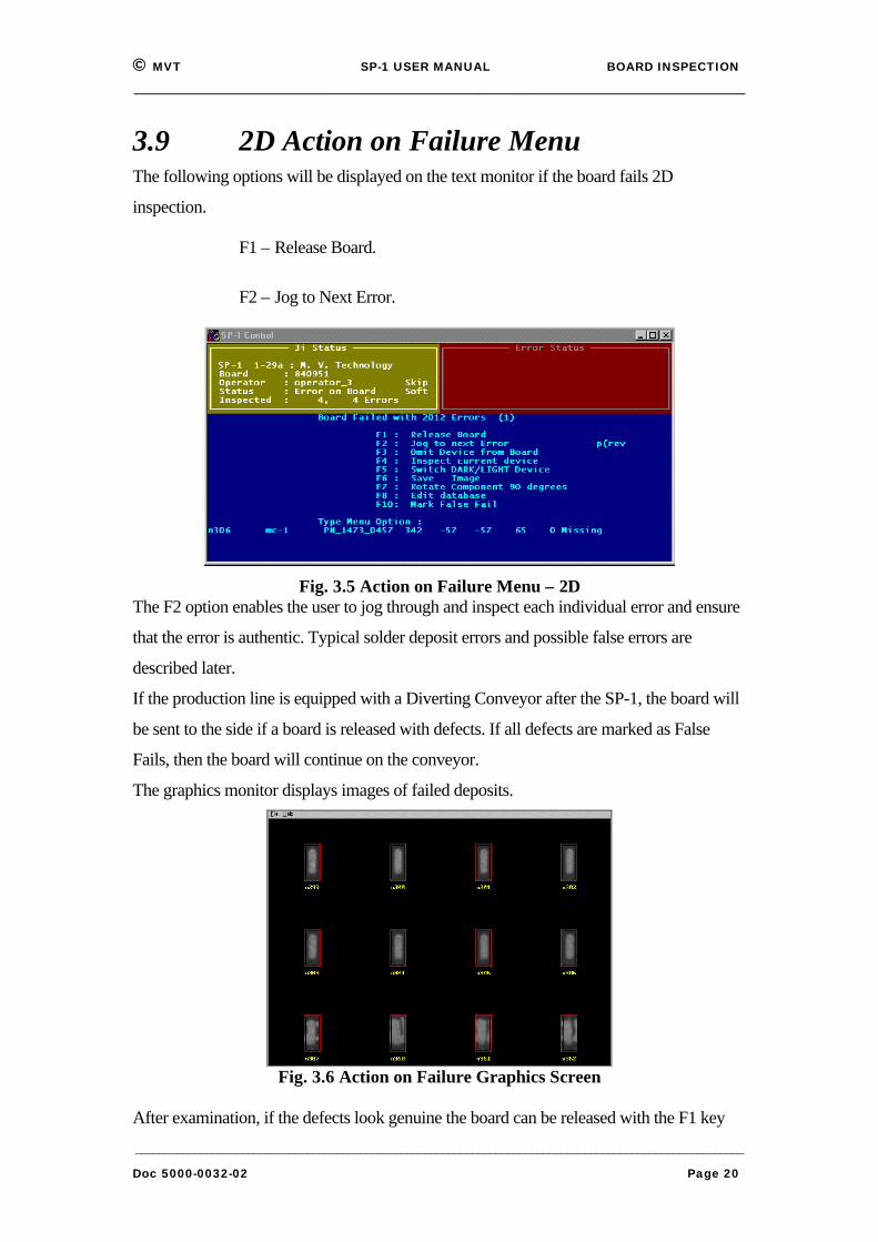
3.9 2D Action on Failure MenuThe following options will be displayed on the text monitor if the board fails 2D
inspection.
⇒ F1 – Release Board.
⇒ F2 – Jog to Next Error.
Fig. 3.5 Action on Failure Menu – 2DThe F2 option enables the user to jog through and inspect each individual error and ensure
that the error is authentic. Typical solder deposit errors and possible false errors are
described later.
If the production line is equipped with a Diverting Conveyor after the SP-1, the board will
be sent to the side if a board is released with defects. If all defects are marked as False
Fails, then the board will continue on the conveyor.
The graphics monitor displays images of failed deposits.
Fig. 3.6 Action on Failure Graphics Screen
After examination, if the defects look genuine the board can be released with the F1 key

© MVT SP-1 USER MANUAL BOARD INSPECTION_____________________________________________________________________
_______________________________________________________________________________________________________Doc 5000-0032-02 Page 21
Fig. 3.7 Sample Graphics Monitor Display after Inspection
Also displayed on the graphics monitor is a position Bullseye Chart and Axes Histograms
that show the area and skew offsets of the deposits on the PCB.
The above example shows that the solder is being deposited slightly offset (-38 microns in
X & 34 microns in Y), covering 77.3% of the desired pad area and with negligible skew.
In addition, statistics are presented on the top left-hand corner of the monitor that detail the
overall mean X and Y offset (in microns) and skews (Theta – in tenths of degrees) of
deposits on the PCB (with their standard deviations included).
© MVT SP-1 USER MANUAL BOARD INSPECTION_____________________________________________________________________
_______________________________________________________________________________________________________Doc 5000-0032-02 Page 22
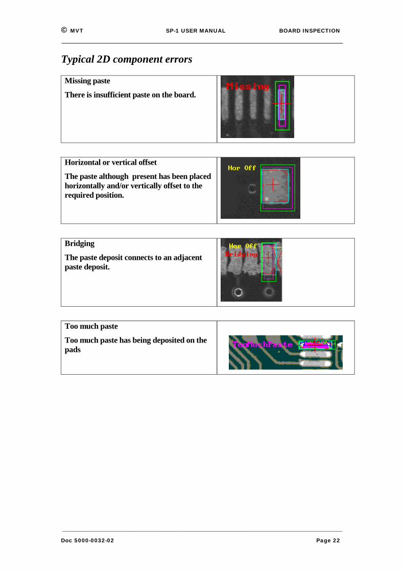
Typical 2D component errors
Missing paste
There is insufficient paste on the board.
Horizontal or vertical offset
The paste although present has been placedhorizontally and/or vertically offset to therequired position.
Bridging
The paste deposit connects to an adjacentpaste deposit.
Too much paste
Too much paste has being deposited on thepads
© MVT SP-1 USER MANUAL BOARD INSPECTION_____________________________________________________________________
_______________________________________________________________________________________________________Doc 5000-0032-02 Page 23
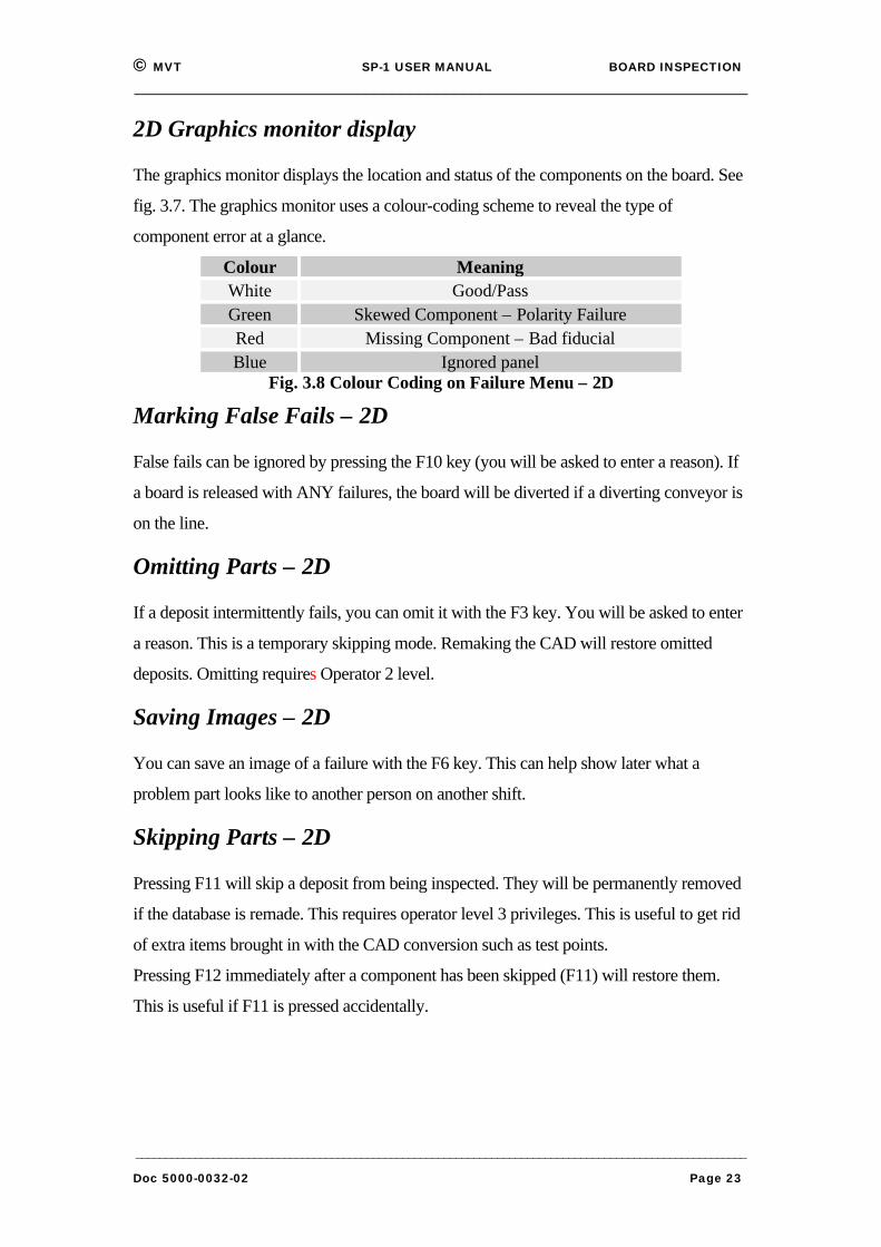
2D Graphics monitor display
The graphics monitor displays the location and status of the components on the board. See
fig. 3.7. The graphics monitor uses a colour-coding scheme to reveal the type of
component error at a glance.
Colour MeaningWhite Good/PassGreen Skewed Component – Polarity FailureRed Missing Component – Bad fiducialBlue Ignored panel
Fig. 3.8 Colour Coding on Failure Menu – 2D
Marking False Fails – 2D
False fails can be ignored by pressing the F10 key (you will be asked to enter a reason). If
a board is released with ANY failures, the board will be diverted if a diverting conveyor is
on the line.
Omitting Parts – 2D
If a deposit intermittently fails, you can omit it with the F3 key. You will be asked to enter
a reason. This is a temporary skipping mode. Remaking the CAD will restore omitted
deposits. Omitting requires Operator 2 level.
Saving Images – 2D
You can save an image of a failure with the F6 key. This can help show later what a
problem part looks like to another person on another shift.
Skipping Parts – 2D
Pressing F11 will skip a deposit from being inspected. They will be permanently removed
if the database is remade. This requires operator level 3 privileges. This is useful to get rid
of extra items brought in with the CAD conversion such as test points.
Pressing F12 immediately after a component has been skipped (F11) will restore them.
This is useful if F11 is pressed accidentally.
© MVT SP-1 USER MANUAL BOARD INSPECTION_____________________________________________________________________
_______________________________________________________________________________________________________Doc 5000-0032-02 Page 24
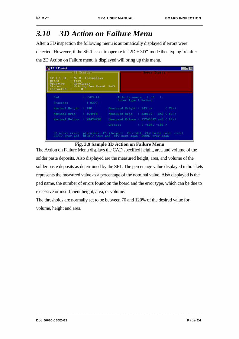
3.10 3D Action on Failure MenuAfter a 3D inspection the following menu is automatically displayed if errors were
detected. However, if the SP-1 is set to operate in “2D + 3D” mode then typing ‘x’ after
the 2D Action on Failure menu is displayed will bring up this menu.
Fig. 3.9 Sample 3D Action on Failure MenuThe Action on Failure Menu displays the CAD specified height, area and volume of the
solder paste deposits. Also displayed are the measured height, area, and volume of the
solder paste deposits as determined by the SP1. The percentage value displayed in brackets
represents the measured value as a percentage of the nominal value. Also displayed is the
pad name, the number of errors found on the board and the error type, which can be due to
excessive or insufficient height, area, or volume.
The thresholds are normally set to be between 70 and 120% of the desired value for
volume, height and area.
© MVT SP-1 USER MANUAL BOARD INSPECTION_____________________________________________________________________
_______________________________________________________________________________________________________Doc 5000-0032-02 Page 25
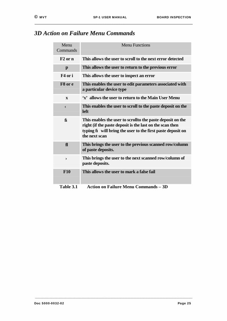
3D Action on Failure Menu Commands
MenuCommands
Menu Functions
F2 or n This allows the user to scroll to the next error detected
p This allows the user to return to the previous error
F4 or i This allows the user to inspect an error
F8 or e This enables the user to edit parameters associated witha particular device type
x ‘x’ allows the user to return to the Main User Menu
← This enables the user to scroll to the paste deposit on theleft
→ This enables the user to scrollto the paste deposit on theright (if the paste deposit is the last on the scan thentyping → will bring the user to the first paste deposit onthe next scan
↓ This brings the user to the previous scanned row/columnof paste deposits.
↑ This brings the user to the next scanned row/column ofpaste deposits.
F10 This allows the user to mark a false fail
Table 3.1 Action on Failure Menu Commands – 3D
© MVT SP-1 USER MANUAL BOARD INSPECTION_____________________________________________________________________
_______________________________________________________________________________________________________Doc 5000-0032-02 Page 26
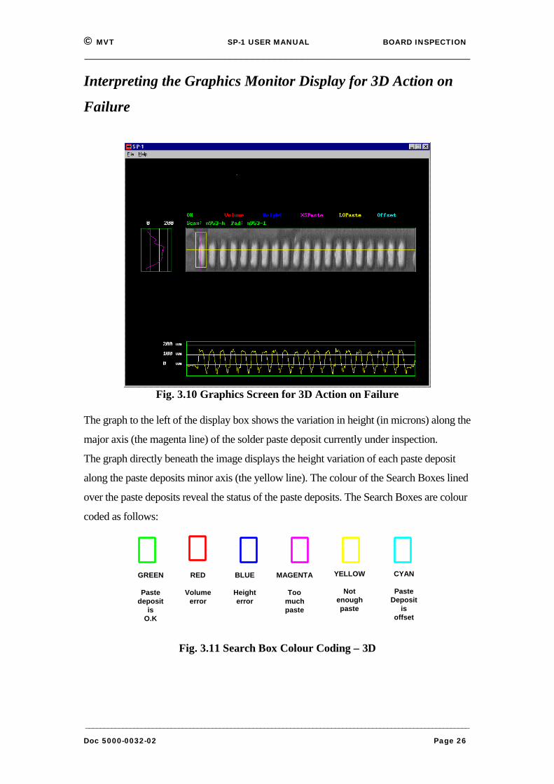
Interpreting the Graphics Monitor Display for 3D Action on
Failure
Fig. 3.10 Graphics Screen for 3D Action on Failure
The graph to the left of the display box shows the variation in height (in microns) along the
major axis (the magenta line) of the solder paste deposit currently under inspection.
The graph directly beneath the image displays the height variation of each paste deposit
along the paste deposits minor axis (the yellow line). The colour of the Search Boxes lined
over the paste deposits reveal the status of the paste deposits. The Search Boxes are colour
coded as follows:
GREEN
Pastedeposit
isO.K
RED
Volumeerror
BLUE
Heighterror
MAGENTA
Toomuchpaste
YELLOW
Notenoughpaste
CYAN
PasteDeposit
isoffset
Fig. 3.11 Search Box Colour Coding – 3D

© MVT SP-1 USER MANUAL BOARD INSPECTION_____________________________________________________________________
_______________________________________________________________________________________________________Doc 5000-0032-02 Page 27
3.11 ShutdownCarry out the following procedure to shutdown the SP-1:
1 From the Main User Menu, Press “F10”: Exit to System.
2 Answer “y” when you are asked “Exiting, are you sure (y/n)?”
3 Shut down the computer (use Windows Shut Down on the Start menu).
4 Use the <Start Button> to shut the system down in the normal manner.
5 Turn the main system power key to “Off”.


![First Revision No. 6036-NFPA 5000-2015 [ Global Input ]€¦ · First Revision No. 6036-NFPA 5000-2015 [ Global Input ] Throughout the document, change “door electrically controlled](https://img.pdfslide.us/doc/110x75/5ecc37693b23a768ed191c72/first-revision-no-6036-nfpa-5000-2015-global-input-first-revision-no-6036-nfpa.jpg)


![First Revision No. 6108-NFPA 5000-2015 [ Global Input ] · PDF fileFirst Revision No. 6108-NFPA 5000-2015 [ Global Input ] ... Design and Construction of Post-Tensioned Slabs-on-Ground](https://img.pdfslide.us/doc/110x75/5a70e96d7f8b9ab6538c57d7/first-revision-no-6108-nfpa-5000-2015-global-input-wwwnfpaorgassetsfilesaboutthecodes50005000pdf.jpg)