Embed Size (px)
Citation preview

®
500 SeriesDry-Block Calibrator
Users Manual
PN 1544875February 2001 Rev.1, 4/02© 2001, 2002 Fluke Corporation. All rights reserved. Printed in USA.All product names are trademarks of their respective companies.

LIMITED WARRANTY & LIMITATION OF LIABILITY
Each Fluke product is warranted to be free from defects in material and workmanship under normal use andservice. The warranty period is one year and begins on the date of shipment. Parts, product repairs, andservices are warranted for 90 days. This warranty extends only to the original buyer or end-user customer ofa Fluke authorized reseller, and does not apply to fuses, disposable batteries, or to any product which, inFluke’s opinion, has been misused, altered, neglected, contaminated, or damaged by accident or abnormalconditions of operation or handling. Fluke warrants that software will operate substantially in accordancewith its functional specifications for 90 days and that it has been properly recorded on non-defective media.Fluke does not warrant that software will be error free or operate without interruption.
Fluke authorized resellers shall extend this warranty on new and unused products to end-user customersonly but have no authority to extend a greater or different warranty on behalf of Fluke. Warranty support isavailable only if product is purchased through a Fluke authorized sales outlet or Buyer has paid theapplicable international price. Fluke reserves the right to invoice Buyer for importation costs ofrepair/replacement parts when product purchased in one country is submitted for repair in another country.
Fluke’s warranty obligation is limited, at Fluke’s option, to refund of the purchase price, free of charge repair,or replacement of a defective product which is returned to a Fluke authorized service center within thewarranty period.
To obtain warranty service, contact your nearest Fluke authorized service center to obtain returnauthorization information, then send the product to that service center, with a description of the difficulty,postage and insurance prepaid (FOB Destination). Fluke assumes no risk for damage in transit. Followingwarranty repair, the product will be returned to Buyer, transportation prepaid (FOB Destination). If Flukedetermines that failure was caused by neglect, misuse, contamination, alteration, accident, or abnormalcondition of operation or handling, including overvoltage failures caused by use outside the product’sspecified rating, or normal wear and tear of mechanical components, Fluke will provide an estimate of repaircosts and obtain authorization before commencing the work. Following repair, the product will be returned tothe Buyer transportation prepaid and the Buyer will be billed for the repair and return transportation charges(FOB Shipping Point).
THIS WARRANTY IS BUYER'S SOLE AND EXCLUSIVE REMEDY AND IS IN LIEU OF ALL OTHERWARRANTIES, EXPRESS OR IMPLIED, INCLUDING BUT NOT LIMITED TO ANY IMPLIED WARRANTYOF MERCHANTABILITY OR FITNESS FOR A PARTICULAR PURPOSE. FLUKE SHALL NOT BE LIABLEFOR ANY SPECIAL, INDIRECT, INCIDENTAL, OR CONSEQUENTIAL DAMAGES OR LOSSES,INCLUDING LOSS OF DATA, ARISING FROM ANY CAUSE OR THEORY.
Since some countries or states do not allow limitation of the term of an implied warranty, or exclusion orlimitation of incidental or consequential damages, the limitations and exclusions of this warranty may notapply to every buyer. If any provision of this Warranty is held invalid or unenforceable by a court or otherdecision-maker of competent jurisdiction, such holding will not affect the validity or enforceability of any otherprovision.
Fluke CorporationP.O. Box 9090Everett, WA 98206-9090U.S.A.
Fluke Europe B.V.P.O. Box 11865602 BD EindhovenThe Netherlands
11/99

i
Table of Contents
Title Page
Introduction ....................................................................................................... 1Contacting Fluke ............................................................................................... 2About this Manual ............................................................................................. 2International Electrical Symbols ....................................................................... 2Specifications .................................................................................................... 3Environmental Conditions................................................................................. 7Safety Guidelines............................................................................................... 7Getting Started................................................................................................... 10
Unpacking ..................................................................................................... 10Set-up ............................................................................................................ 10Power ............................................................................................................ 10Changing the Supply Voltage and Fuses on Models 515 and 517................ 11Changing the Display Units .......................................................................... 11Setting the Temperature ................................................................................ 12Setting the High Limit Parameter.................................................................. 12
Front Panel......................................................................................................... 12Rear Panel.......................................................................................................... 14Cooling Fan ....................................................................................................... 17Constant Temperature Block Assembly ............................................................ 18Inserts and Tongs............................................................................................... 20Well Insulator for Model 517 ............................................................................ 21Tips for Calibrating Probes ............................................................................... 22Operating the Calibrator .................................................................................... 22
Monitoring the Well Temperature................................................................. 26Resetting the Heater Cut-Out ........................................................................ 26Setting the Temperature Set-Point ................................................................ 26
Accessing the Programmable Set-Points .................................................. 27Adjusting a Set-Point Value ..................................................................... 27Temperature Scale Units........................................................................... 28
Setting a Scan Rate........................................................................................ 28Enabling or Disabling Scanning ............................................................... 28Scan Rate .................................................................................................. 29
Testing a Thermal Switch ............................................................................. 29Enabling the Switch Test .......................................................................... 29Display Hold ............................................................................................. 29Switch Wiring ........................................................................................... 30Switch Test Example ................................................................................ 30
Ramp and Soak Program Menu .................................................................... 30Setting the Number of Program Set-points............................................... 31

500 SeriesUsers Manual
ii
Setting the Temperature Set-Points .......................................................... 31Setting the Program Soak Time ................................................................ 32Selecting a Program Function Mode......................................................... 32Starting and Stopping the Program........................................................... 33
Secondary Functions ......................................................................................... 33Monitoring the Heating Power...................................................................... 33Setting the Proportional Band ....................................................................... 34Configuring the Temperature Controller....................................................... 35
Setting the High Limit Parameters............................................................ 36Serial Interface Parameters ....................................................................... 36IEEE-488 Parameters................................................................................ 36Calibration Parameters.............................................................................. 37
Methods for Calibrating Probes......................................................................... 37Direct Calibration.......................................................................................... 37Comparison Calibration ................................................................................ 38Calibrating Multiple Probes .......................................................................... 38
Dry-Block Characteristics ................................................................................. 39Vertical Gradient........................................................................................... 39Stabilization and Accuracy............................................................................ 39
Digital Communication Interface ...................................................................... 39RS-232 Communications .............................................................................. 39
Cable Wiring and Data Protocol ............................................................... 39Setup ......................................................................................................... 40Baud Rate.................................................................................................. 40Sample Period ........................................................................................... 40Duplex Mode ............................................................................................ 42Linefeed .................................................................................................... 42
RS-232 Operation.......................................................................................... 42IEEE-488 Communications .......................................................................... 42
Setup ......................................................................................................... 43IEEE-488 Address .................................................................................... 43Termination............................................................................................... 43
IEEE-488 Operation for Models 514, 515, and 517...................................... 43IEEE-488 Operation for Model 518.............................................................. 43RS-232 and IEEE-488 Interface Commands................................................. 45
Calibrating Models 514, 517, and 518 (cold side)............................................. 49Calibration Equipment .................................................................................. 49Calibration Parameters .................................................................................. 49
R0 .............................................................................................................. 49ALPHA ..................................................................................................... 49DELTA ..................................................................................................... 49BETA........................................................................................................ 49
Calibration Procedure.................................................................................... 50Calibrating Models 515 and 518 (hot side) ....................................................... 51
Calibration Points.......................................................................................... 51Measuring the Set-point Error....................................................................... 51Computing R0 and ALPHA........................................................................... 52Calibration Example...................................................................................... 52
Care and Maintenance ....................................................................................... 54Replacing the Fuses....................................................................................... 55Troubleshooting ............................................................................................ 55
Replacement Parts ............................................................................................. 57CE Comments.................................................................................................... 59
EMC Directive .............................................................................................. 59Low Voltage Directive (Safety) .................................................................... 59

iii
List of Tables
Table Title Page
1. International Electrical Symbols............................................................................ 22. Models 514 and 517 Specifications ....................................................................... 33. Model 515 Specifications ...................................................................................... 44. Model 518 Specifications ...................................................................................... 55. Heating and Stabilization Times............................................................................ 126. Inserts for Models 514 and 517 ............................................................................. 207. Inserts for Model 515 and Hot Side of Model 518 ................................................ 208. Inserts for Cold Side of Model 518........................................................................ 219. Ramp and Soak Program Modes............................................................................ 3210. IEEE-488 Communication Commands.................................................................. 4611. Troubleshooting the Calibrator .............................................................................. 5612. Replacement Parts.................................................................................................. 57

500 SeriesUsers Manual
iv

v
List of Figures
Figure Title Page
1. Models 514, 515, and 517 Front Panel Features.................................................... 132. Model 518 Front Panel Features ............................................................................ 143. Model 514 Rear Panel Features ............................................................................. 154. Models 515 and 517 Rear Panel Features.............................................................. 165. Model 518 Rear Panel Features ............................................................................. 176. Constant Temperature Block Assembly for Models 514 and 517 ......................... 187. Constant Temperature Block Assembly for Model 515 ........................................ 198. Constant Temperature Block Assemblies for Model 518...................................... 199. Well Insulator for Model 517 ................................................................................ 2110. Flowchart of Calibrator Functions (Part 1) for All Models ................................... 2311. Flowchart of Calibrator Functions (Part 2) for Model 515.................................... 2412. Flowchart of Calibrator Functions (Part 2) for Models 514/517/518 .................... 2513. Well Temperature Fluctuation at Various Proportional Band Settings ................. 3414. Serial Cable Wiring Diagram................................................................................. 4115. IEEE Converter Box Switch Settings for Model 518 ............................................ 4416. Calibration Example for Model 515 and the Hot Side of Model 518.................... 5317. Fuse Access for Models 515 and 517 .................................................................... 55

500 SeriesUsers Manual
vi

1
500 SeriesDry-Block Calibrator
IntroductionThe Fluke 500 Series Dry-Block Calibrators may be used as portable or benchtopinstruments for calibrating temperature probes.
These dry-block calibrators feature interchangeable inserts to accommodate a wide rangeof temperature probe diameters.
The calibrator controller uses a precision, platinum RTD as a sensor. Models 514 and 517use thermoelectric modules (TEDs) to control the heating and cooling of the well. Model515 uses a solid state relay (triac) to control the heating of the well. Model 518 uses bothTEDs and a triac to control heating and cooling.
The LED display continuously shows the current well temperature. You can use the frontpanel buttons to easily set any temperature within the range specified for the calibrator.
The dry-block calibrators are designed for portability, moderate cost, and easy operation.To safely and accurately calibrate temperature sensors and devices, familiarize yourselfwith the calibrator’s safety guidelines and operating procedures described in this manual.
500 SeriesUsers Manual
2
Contacting FlukeTo order accessories, receive assistance, or locate the nearest Fluke distributor or ServiceCenter, call:
• USA: 1-888-99-FLUKE (1-888-993-5853)
• Canada: 1-800-36-FLUKE (1-800-363-5853)
• Europe: +31 402-678-200
• Japan: +81-3-3434-0181
• Singapore: +65-738-5655
• Anywhere in the world: +1-425-446-5500
Address correspondence to:
Fluke CorporationP.O. Box 9090Everett, WA 98206-9090USA
Fluke Europe B.V.P.O. Box 11865602 BD EindhovenThe Netherlands
Visit us on the World Wide Web at www.fluke.com.
About this ManualThis manual describes Models 514, 515, 517, and 518 dry-block calibrators and theoptions for each model. Except where noted, the descriptions and instructions in thismanual apply to all models.
In this manual, a Warning identifies conditions and actions that pose hazards to the user.
A Caution identifies conditions and actions that may damage the calibrator or thedevices being calibrated.
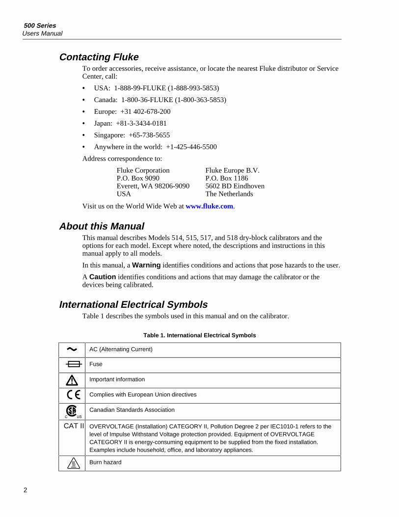
International Electrical SymbolsTable 1 describes the symbols used in this manual and on the calibrator.
Table 1. International Electrical Symbols
AC (Alternating Current)
Fuse
Important information
Complies with European Union directives
Canadian Standards Association
CAT II OVERVOLTAGE (Installation) CATEGORY II, Pollution Degree 2 per IEC1010-1 refers to thelevel of Impulse Withstand Voltage protection provided. Equipment of OVERVOLTAGECATEGORY II is energy-consuming equipment to be supplied from the fixed installation.Examples include household, office, and laboratory appliances.
Burn hazard

Dry-Block CalibratorSpecifications
3
SpecificationsTables 2 through 4 give the specifications for the 500 Series Dry-Block Calibrators.
NotesAccuracy specifications are applicable for a one-year calibration interval.In keeping with normal, prudent metrology practices, a short-cycle intervalof six months is recommended for new units during the first year.
Temperature ranges and scan rates may vary depending on ambienttemperature and line voltage.
Table 2. Models 514 and 517 Specifications
Power 115 VAC (±10 %), 50/60 Hz, 230 VAC (±10 %), 350 W
Ambient Temperature 5 °C to 50 °C (40 °F to 120 °F)
Model 514 Model 517Operating Range
–25 °C to +140 °C (–13 °F to +284 °F) at 23.3 °C (74 °F) ambient
–45 °C to +140 °C(–49 °F to +284 °F)at 23 °C (74 °F) ambient
Resolution 0.01 °C or 0.01 °F
Accuracy of drilled wells With reference: ±0.05 °C (0.09 °F)Without reference: –20 °C ±0.23 °C (0.42 °F); 0 °C ±0.1 °C (0.18 °F)140 °C ±0.45 °C (0.81 °F)
Accuracy of center well(with 0.25 in inserts)
±0.1°C (0.18 °F)
Uniformity of drilled wells ±0.05 °C (0.09 °F)
Uniformity of center well todrilled wells (with 0.25 ininsert
–20 °C ±0.23 °C (0.42 °F); 0 °C ±0.01 °C (0.18 °F); 140 °C ±0.45 °C(0.81 °F)
Control Stability ±0.02 °C (0.04 °F)
Controller Hybrid analog/digital controller with data retention
Test Wells One 3/4 in dia. x 6 in deep, two 1/4 in dia. x 6 in deep, one 3/16 in dia. x 6in deep, and one 1/8 in x 6 in deep
Size 12.5 in H x 8 in W x 10.5 in D (318 mm x 203 mm x 267 mm)
Weight 30 lb including well insert (13.6 kg)
Safety OVERVOLTAGE (Installation) CATAGORY II, Pollution Degree 2 perIEC1010-1
Computer Interface RS-232 (IEEE optional)
Fault Protection Sensor burnout protection, over-temperature cut-out, and electrical fuses

500 SeriesUsers Manual
4
Table 3. Model 515 Specifications
Range 50 °C to 600 °C (95 °F to 1112 °F) at 25 °C (77 °F) ambient
Accuracy(with 0.25 in probe)
±0.1 °C to 300 °C, ±0.5 °C to 600 °C
Stability ±0.02 °C to 300 °C, ±0.05 °C to 600 °C
Uniformity 100 °C ±0.05 °C, typical ±0.03 °C; 600 °C ±0.2 °C, typical ±0.1 °C
Test Wells 6 in deep (multi-hole inserts available)
Computer Interface RS-232 interface (IEEE optional)
Heating Time to Max 30 minutes from 100 °C to 600 °C
Resolution 0.01 °C or 0.01 °F
Display LED, °C or °F, user selectable
Size 12.5 in H x 8 in W x 10.5 in D (318 mm x 203 mm x 267 mm)
Weight 25 lb (11.4 kg)
Power 115 VAC (±10 %), 50/60 Hz, 230 VAC [±10 %], 50/60 Hz, 1000 W
Controller Hybrid analog/digital controller with data retention
Heater Heater element PWM
Cooling 2 speed internal fan
Fault Protection Sensor burnout protection, over temperature thermal cut-out, electrical fuse(10 A 115 VAC [±10 %], 5 A 230 VAC [±10 %])
Ambient Temperature 5 °C to 50 °C (41 °F to 122 °F)
Safety OVERVOLTAGE (Installation) CATAGORY II, Pollution Degree 2 perIEC1010-1
Cooling time 2.5 hours from 600 °C to 100 °C
Dry-Block CalibratorSpecifications
5
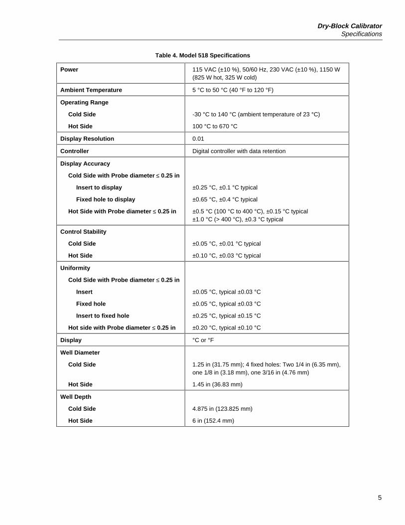
Table 4. Model 518 Specifications
Power 115 VAC (±10 %), 50/60 Hz, 230 VAC (±10 %), 1150 W(825 W hot, 325 W cold)
Ambient Temperature 5 °C to 50 °C (40 °F to 120 °F)
Operating Range
Cold Side
Hot Side
-30 °C to 140 °C (ambient temperature of 23 °C)
100 °C to 670 °C
Display Resolution 0.01
Controller Digital controller with data retention
Display Accuracy
Cold Side with Probe diameter ≤ 0.25 in
Insert to display
Fixed hole to display
Hot Side with Probe diameter ≤ 0.25 in
±0.25 °C, ±0.1 °C typical
±0.65 °C, ±0.4 °C typical
±0.5 °C (100 °C to 400 °C), ±0.15 °C typical±1.0 °C (> 400 °C), ±0.3 °C typical
Control Stability
Cold Side
Hot Side
±0.05 °C, ±0.01 °C typical
±0.10 °C, ±0.03 °C typical
Uniformity
Cold Side with Probe diameter ≤ 0.25 in
Insert
Fixed hole
Insert to fixed hole
Hot side with Probe diameter ≤ 0.25 in
±0.05 °C, typical ±0.03 °C
±0.05 °C, typical ±0.03 °C
±0.25 °C, typical ±0.15 °C
±0.20 °C, typical ±0.10 °C
Display °C or °F
Well Diameter
Cold Side
Hot Side
1.25 in (31.75 mm); 4 fixed holes: Two 1/4 in (6.35 mm),one 1/8 in (3.18 mm), one 3/16 in (4.76 mm)
1.45 in (36.83 mm)
Well Depth
Cold Side
Hot Side
4.875 in (123.825 mm)
6 in (152.4 mm)
500 SeriesUsers Manual
6
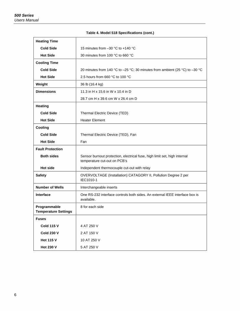
Table 4. Model 518 Specifications (cont.)
Heating Time
Cold Side
Hot Side
15 minutes from –30 °C to +140 °C
30 minutes from 100 °C to 660 °C
Cooling Time
Cold Side
Hot Side
20 minutes from 140 °C to –25 °C; 30 minutes from ambient (25 °C) to –30 °C
2.5 hours from 660 °C to 100 °C
Weight 36 lb (16.4 kg)
Dimensions 11.3 in H x 15.6 in W x 10.4 in D
28.7 cm H x 39.6 cm W x 26.4 cm D
Heating
Cold Side
Hot Side
Thermal Electric Device (TED)
Heater Element
Cooling
Cold Side
Hot Side
Thermal Electric Device (TED), Fan
Fan
Fault Protection
Both sides
Hot side
Sensor burnout protection, electrical fuse, high limit set, high internaltemperature cut-out on PCB’s
Independent thermocouple cut-out with relay
Safety OVERVOLTAGE (Installation) CATAGORY II, Pollution Degree 2 perIEC1010-1
Number of Wells Interchangeable inserts
Interface One RS-232 interface controls both sides. An external IEEE interface box isavailable.
ProgrammableTemperature Settings
8 for each side
Fuses
Cold 115 V
Cold 230 V
Hot 115 V
Hot 230 V
4 AT 250 V
2 AT 150 V
10 AT 250 V
5 AT 250 V
Dry-Block CalibratorEnvironmental Conditions
7
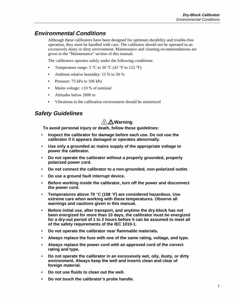
Environmental ConditionsAlthough these calibrators have been designed for optimum durability and trouble-freeoperation, they must be handled with care. The calibrator should not be operated in anexcessively dusty or dirty environment. Maintenance and cleaning recommendations aregiven in the “Maintenance” section of this manual.
The calibrators operates safely under the following conditions:
• Temperature range: 5 °C to 50 °C (41 °F to 122 °F)
• Ambient relative humidity: 15 % to 50 %
• Pressure: 75 kPa to 106 kPa
• Mains voltage: ±10 % of nominal
• Altitudes below 2000 m
• Vibrations in the calibration environment should be minimized
Safety GuidelinesWarning
To avoid personal injury or death, follow these guidelines:
• Inspect the calibrator for damage before each use. Do not use thecalibrator if it appears damaged or operates abnormally.
• Use only a grounded ac mains supply of the appropriate voltage topower the calibrator.
• Do not operate the calibrator without a properly grounded, properlypolarized power cord.
• Do not connect the calibrator to a non-grounded, non-polarized outlet.
• Do use a ground fault interrupt device.
• Before working inside the calibrator, turn off the power and disconnectthe power cord.
• Temperatures above 70 °C (158 °F) are considered hazardous. Useextreme care when working with these temperatures. Observe allwarnings and cautions given in this manual.
• Before initial use, after transport, and anytime the dry-block has notbeen energized for more than 10 days, the calibrator must be energizedfor a dry-out period of 1 to 2 hours before it can be assumed to meet allof the safety requirements of the IEC 1010-1.
• Do not operate the calibrator near flammable materials.
• Always replace the fuse with one of the same rating, voltage, and type.
• Always replace the power cord with an approved cord of the correctrating and type.
• Do not operate the calibrator in an excessively wet, oily, dusty, or dirtyenvironment. Always keep the well and inserts clean and clear offoreign material.
• Do not use fluids to clean out the well.
• Do not touch the calibrator’s probe handle.

500 SeriesUsers Manual
8
• Always be aware of the well temperature. The temperature of the probeterminal is the same as the temperature shown on the display. Forexample, if the unit is set to 600 °C and the display reads 600 °C, thewell is at 600 °C.
• Do not touch the metal on the top of the calibrator while the calibrator ishot. The area around the probe terminal can get extremely hot.
• Insert and remove probes only when the calibrator is set attemperatures less than 50 °C.
• The air over the well can get hot enough to burn you.
• Do not turn off the calibrator at temperatures higher than 100 °C. Selecta set-point less than 100 °C and let the calibrator cool down beforeturning it off.
• Do not remove inserts while the calibrator temperature is greater than50 °C. Inserts are at the temperature shown on the display.
• Always use the tongs supplied with the calibrator to remove the inserts.After removing probes, always place the probes on a temperature-resistant surface until the probes are at room temperature.
• Always carry the calibrator in an upright position to prevent the insertsfrom dropping out.
• Overhead clearance is required. Do not place the calibrator under acabinet or any other structure.
• Always leave enough clearance above the calibrator to allow for safeand easy insertion and removal of probes.
• Always operate the instrument at room temperatures between 41 °F and122 °F (5 °C to 50 °C). Allow sufficient air circulation by leaving at least6 inches (15 cm) of clearance around the calibrator.
• Do not place aluminum inserts in high-temperature calibrators that canheat up above 400 °C.
• Do not use the calibrator for applications other than calibration work.
• Do not use the calibrator in environments other than those listed in thismanual.
• Use extra caution when operating the calibrator at high temperaturesfor extended periods of time.
• Unattended operation at high temperatures is not recommended.
• The high temperatures present in the calibrator may result in fires andsevere burns if safety precautions are not observed.
• Do not use the calibrator without adequate training.
• Do not use in wet environments.
Dry-Block CalibratorSafety Guidelines
9
CautionTo avoid possible damage to the calibrator or the probes beingcalibrated:
• Do not change the calibration constants from the factory settings. Thefactory settings are important for the safety and proper operation of thecalibrator.
• Always turn off the calibrator immediately if the mains power supplyfluctuates. Power fluctuations could damage the calibrator. Wait untilthe power has stabilized before re-energizing the calibrator.
• Never allow foreign material into the probe holes. Fluids and othermaterials can damage the calibrator or cause binding and damage toyour probe.
• Allow for probe expansion inside the well as the dry block heats.
• Do not calibrate probes whose handles can be damaged by the hot airabove the well. Use of a probe shield is recommended. Check the probehandle temperature limit before calibration.
• Do not place into the well any objects other than the inserts supplied forthe calibrator.
• The master reset sequence should be performed only by authorizedpersonnel if no other action is successful in correcting a malfunction.You must have a copy of the most recent Report of Calibration torestore the calibration parameters.
• For Model 517, always use the well insulator. See “Well Insulator forModel 517”.
• Operating the calibrator continuously at high temperature can shortenthe lifetimes of the heater and other calibrator components.
• If the calibrator is used in a manner not in accordance with theequipment design, the calibrator may malfunction or safety hazardsmay arise.
Warning• Fluke 500 Series Dry-Block Calibrators are intended for indoor operation only.

500 SeriesUsers Manual
10
Getting Started
UnpackingUnpack the calibrator carefully and inspect it for any damage that may have occurredduring shipment. If there is shipping damage, notify the carrier immediately.
Verify that the following components are present:
• Dry-block calibrator
• Insert (One insert, specified by the customer, is include with the calibrator. SeeTables 6 through 8.)
• One set of tongs
• Power cord
• Users manual
• Well insulator (517 only)
• RS-232 cable
Set-up
WarningTo avoid personal injury:
Before initial use, after transport, and anytime the dry-blockhas not been energized for more than 10 days, the calibratormust be energized for a dry-out period of 1 to 2 hours before itcan be assumed to meet all of the safety requirements of theIEC 1010-1.
Place the calibrator on a flat surface surrounded by at least 6 inches (15 cm) of free spacewith no overhead obstructions. Carefully slide the insert into the well. Inserts should havethe smallest hole diameter possible that allows the probe to slide in and out easily. Insertsof various sizes are available from Fluke. The well must be clear of any foreign objects,dirt and grit before the insert is installed. Install the insert so the two small tong holes arepositioned upward.
PowerVerify that the nominal ac voltage corresponds to that indicated on the back of thecalibrator. Typically this will be 115 VAC (±10 %), 50/60 Hz or 230 VAC (±10 %),50/60 Hz. Plug the calibrator power cord into a grounded ac outlet of the proper voltage,frequency, and current capability.
For Models 514, 515, and 517, turn the calibrator on using the power switch on the rearpanel.
For Model 518, use the power switches on the front panel to turn on the hot and coldsides at the same time. (An error occurs if both sides are not turned on within 5 secondsof each other. Refer to Table 11.)
The fan should begin quietly blowing air through the calibrator and the front paneldisplay should illuminate after 3 seconds. After a brief self-test, the controller shouldbegin normal operation. The calibrator will begin to heat to the previously programmedtemperature set-point. The front panel LED display will indicate the actual dry-blocktemperature. If the unit fails to operate, check the power connection.
Dry-Block CalibratorSafety Guidelines
11
Changing the Supply Voltage and Fuses on Models 515 and 517To change the supply voltage and fuses on Models 515 and 517, proceed as follows:
WarningTo avoid electric shock, burns, or damage to equipment:
• Always replace the fuses with ones of the correct rating,voltage, and type.
• Always replace the power cord with an approved cord of thecorrect rating and type.
1. Turn off the calibrator and unplug it from the ac outlet.
2. Insert a flat-blade screwdriver into the slot at the top of the power entry module(PEM). (Refer to Figure 17 under “Replacing the Fuses” in the “Care andMaintenance” section.) Gently open the module to access the fuse holder.
3. Remove the fuse holder. Replace the fuses with the correct fuses for the new voltage.
4. Replace the fuse holder, turning it so that the correct voltage shows in the voltagewindow on the PEM. Close the PEM.
5. Model 515: On the back of the calibrator, switch the HEATER VOLTAGESELECTOR to the correct voltage.
NoteFor proper operation, the HEATER VOLTAGE SELECTOR and PEMvoltage window must match.
6. You may need to change the power cord to fit the ac outlet. Compatible power cordsinclude the following:
• 230 VAC Europe: 10 A approved cord with a CEE 7/7 plug (Schuko)
• 230 VAC United States: 15 A approved cord with a NEMA 6-15 straight-bladeplug
• 115 VAC United States: 15 A approved cord with a NEMA 5-15 plug
7. Connect the calibrator to the ac outlet.
Changing the Display UnitsThe calibrator can display temperatures in degrees Celsius or Fahrenheit. Thetemperature units are set to Celsius at the factory. To switch between temperature units,use one of the following methods:
Press UP for 2-3 seconds until the display flashes.
Or
1. Press SET three times to display the units; then press UP or DOWN to change the units
2. Press SET to store the change or EXIT to proceed without storing the change.

500 SeriesUsers Manual
12
Setting the TemperatureThe later section “Setting the Temperature Set-Point” explains in detail how to set thetemperature set-point on the calibrator using the front panel keys. The procedure issummarized here.
1. Press SET twice to access the set-point value.
2. Press UP or DOWN to change the set-point value.
3. Press SET to program in the new set-point.
4. Press and hold EXIT to return to the temperature display.
When you change the set-point temperature, the controller switches the well heater on oroff to raise or lower the temperature. For Models 514, 515, and 517 the cycle indicator, atwo color LED, will also indicate on (red and heating) or off (green and cooling). Thedisplayed well temperature gradually changes until it reaches the set-point temperature.The well may require 5 to 30 minutes to reach the set-point depending on the span.Another 5 to 10 minutes is required for the temperature to stabilize. Table 5 shows theheating and stabilization times required for the 500 Series Calibrator models.
Table 5. Heating and Stabilization Times
Model Heating Time
Time to Stabilize within0.1 °C of Set-Point
(after reaching set-point)Time to Reach Maximum Stability
(after initial stabilization)
514/517 Ambient to 140 °C(284 °F): 15 minutes
5 to 10 minutes 15 to 20 minutes
515 Ambient to maximum:15 minutes
5 to 10 minutes 20 to 30 minutes
518 Ambient to maximum:30 minutes
10 to 20 minutes 20 to 30 minutes
* Time required depends on the magnitude of the temperature change.
Setting the High Limit ParameterThe high limit parameter is set at the factory to the calibrator’s maximum temperaturelimit. If a test probe’s maximum temperature is less than the high limit parameter, set theparameter to the probe’s maximum temperature. See “Setting the Calibrator’s OperatingParameters”.
Front PanelFigure 1 describes the front panel features for Models 514, 515, and 517 (Model 514 isshown). Figure 2 describes the front panel features for Model 518.

Dry-Block CalibratorFront Panel
13
SET UPDOWN EXIT
CONTROLINDICATOR
DRY BLOCK CALIBRATOR514
1 2
3
abv15f.eps
A Control Indicator (Models 514, 515, and 517): The Control Indicator is a two color, light emittingdiode. This indicator shows the ratio of heating to cooling. When the indicator is constant red, thewell is heating; when it is constant green, the well is cooling. When the indicator is flashing then thetemperature is being held constant.
B Controller Display: The digital display shows the set-points, actual well temperatures, and variouscalibrator functions, settings, and constants. The display shows temperatures in °C or °F with aresolution of one-hundredth of a degree C or F.
C Controller Keypad: The control buttons (SET, DOWN, UP, and EXIT) are used to set the calibratortemperature set-point, access and set other operating parameters, and access and set calibrationparameters.
SET: Used to step through the menu and to store parameters to the displayed value.
DOWN: Used to decrement the displayed value of parameters.
UP: Used to increment the displayed value.
EXIT: Used to skip a parameter without storing the parameter value. Hold down EXIT to exit the menu
and display the temperature.
Figure 1. Models 514, 515, and 517 Front Panel Features

500 SeriesUsers Manual
14
SET UPDOWN EXIT
POWER
SET UPDOWN EXIT
POWER
DRY BLOCK CALIBRATOR518
COLD SIDE • -30˚C to +140˚C
SIDE A SIDE B
HOT SIDE • 100˚C to +670˚C
1
3
Hot side
2 1 2
3
Cold side
abv12f.eps
A Controller Displays: The digital display shows the set-points, actual well temperatures, and variouscalibrator functions, settings, and constants for the hot (left) and cold (right) sides of the calibrator.The display shows temperatures in °C or °F with a resolution of one-hundredth of a degree C or F.
B Power Switches: The power switches turn on power to the hot (left) and cold (right) sides of thecalibrator.
C Controller Keypads: The control buttons (SET, DOWN, UP, and EXIT) are used to set the calibratortemperature set-point, access and set other operating parameters, and access and set calibrationparameters for the hot (left) and cold (right) sides of the calibrators.
SET: Used to step through the menu and to store parameters to the displayed value.
DOWN: Used to decrement the displayed value of parameters.
UP: Used to increment the displayed value.
EXIT: Used to skip a parameter without storing the parameter value. Hold down EXIT to exit the menu
and display the temperature.
Figure 2. Model 518 Front Panel Features
Rear PanelFigures 3 through 5 describe the rear panel features.
Dry-Block CalibratorRear Panel
15
DISPLAY HOLD RS-232
POWER115V 50/60 Hz
350W 2.5A3A 250V
FLUKE CORPORATIONMADE IN USA
www.fluke.com
CAT 300V
IEEE-488(option)
6
43
1
2
5
abv19f.eps
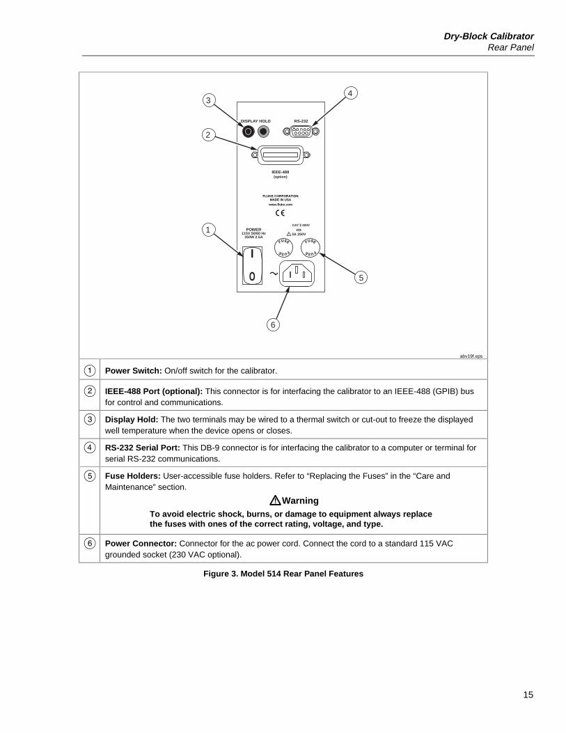
A Power Switch: On/off switch for the calibrator.
B IEEE-488 Port (optional): This connector is for interfacing the calibrator to an IEEE-488 (GPIB) busfor control and communications.
C Display Hold: The two terminals may be wired to a thermal switch or cut-out to freeze the displayedwell temperature when the device opens or closes.
D RS-232 Serial Port: This DB-9 connector is for interfacing the calibrator to a computer or terminal forserial RS-232 communications.
E Fuse Holders: User-accessible fuse holders. Refer to “Replacing the Fuses” in the “Care andMaintenance” section.
WWarningTo avoid electric shock, burns, or damage to equipment always replacethe fuses with ones of the correct rating, voltage, and type.
F Power Connector: Connector for the ac power cord. Connect the cord to a standard 115 VACgrounded socket (230 VAC optional).
Figure 3. Model 514 Rear Panel Features

500 SeriesUsers Manual
16
DISPLAY HOLD RS-232
FLUKE CORPORATION MADE IN USAwww.fluke.com
IEEE-488 (option)
DISPLAY HOLD
RS-232
HEATERVOLTAGE
SELECTOR
POWER115V 10A F 250V 115V/230A 50/60 Hz 230V 5A F 250V 1000W
FLUKE CORPORATIONMADE IN USA
www.fluke.com
CAT 300V
POWER115V 4AT 250V 115V/230V 50/60 Hz 230V 3.15AT 250V 350W
CAT 300V
IEEE-488 (option)
4
4
3
23
2
1
1
5
515
517
abv17f.eps
A Power Entry Module (PEM): The power entry module contains the ac power connector, power switchand fuses. For information on fuse replacement, see “Replacing the Fuses” in the “Care andMaintenance” section.
B IEEE-488 Port (optional): This connector is for interfacing the calibrator to an IEEE-488 (GPIB) busfor control and communications.
C Display Hold: The two terminals may be wired to a thermal switch or cut-out to freeze the displayedwell temperature when the device opens or closes.
D RS-232 Serial Port: This DB-9 connector is for interfacing the calibrator to a computer or terminal forserial RS-232 communications.
E Heater voltage selector switch: This switch on Model 515 lets you change the calibrator’s ac supplyvoltage. For information on changing the supply voltage, see “Changing the Supply Voltage on Model515”.
Figure 4. Models 515 and 517 Rear Panel Features
Dry-Block CalibratorCooling Fan
17
RS-232
POWER115V 50/60 Hz230V 50/50 Hz
1150W
COLD SIDE HOT SIDE
115VAC 50/60 Hz 4A T 250V230VAC 50/60 Hz 2A T 250V
325W
115VAC 50/60 Hz 10A F 250V230VAC 50/60 Hz 5A F 250V
825W
FLUKE CORPORATIONMADE IN USA
www.fluke.com
CAT 300V
1 3
2
FUSE
FUSE
FUSE
FUSE
FUSE
FUSE
FUSE
FUSE
abv13f.eps
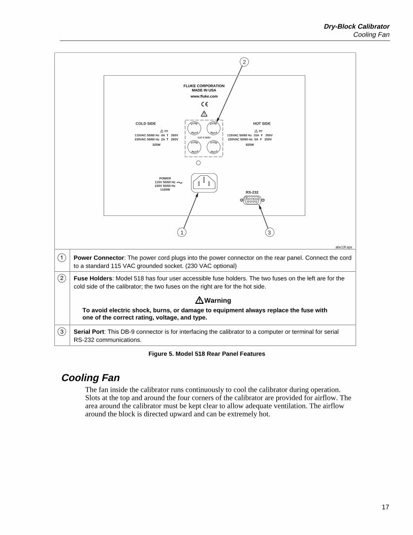
A Power Connector: The power cord plugs into the power connector on the rear panel. Connect the cordto a standard 115 VAC grounded socket. (230 VAC optional)
B Fuse Holders: Model 518 has four user accessible fuse holders. The two fuses on the left are for thecold side of the calibrator; the two fuses on the right are for the hot side.
WWarningTo avoid electric shock, burns, or damage to equipment always replace the fuse withone of the correct rating, voltage, and type.
C Serial Port: This DB-9 connector is for interfacing the calibrator to a computer or terminal for serialRS-232 communications.
Figure 5. Model 518 Rear Panel Features
Cooling FanThe fan inside the calibrator runs continuously to cool the calibrator during operation.Slots at the top and around the four corners of the calibrator are provided for airflow. Thearea around the calibrator must be kept clear to allow adequate ventilation. The airflowaround the block is directed upward and can be extremely hot.
500 SeriesUsers Manual
18
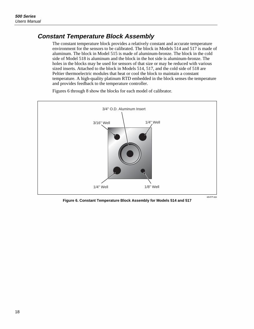
Constant Temperature Block AssemblyThe constant temperature block provides a relatively constant and accurate temperatureenvironment for the sensors to be calibrated. The block in Models 514 and 517 is made ofaluminum. The block in Model 515 is made of aluminum-bronze. The block in the coldside of Model 518 is aluminum and the block in the hot side is aluminum-bronze. Theholes in the blocks may be used for sensors of that size or may be reduced with varioussized inserts. Attached to the block in Models 514, 517, and the cold side of 518 arePeltier thermoelectric modules that heat or cool the block to maintain a constanttemperature. A high-quality platinum RTD embedded in the block senses the temperatureand provides feedback to the temperature controller.
Figures 6 through 8 show the blocks for each model of calibrator.
3/4" O.D. Aluminum Insert
3/16" Well 1/4" Well
1/4" Well 1/8" Well
abv07f.eps
Figure 6. Constant Temperature Block Assembly for Models 514 and 517

Dry-Block CalibratorConstant Temperature Block Assembly
19
1/4 In Wells
abv03f.eps
Figure 7. Constant Temperature Block Assembly for Model 515
Cold SideHot Side
1/4 In Wells
3/16 In Well
1/4 InWell
1 1/4 InWells
1/8 InWell
1/4 InWell
abv16f.eps
Figure 8. Constant Temperature Block Assemblies for Model 518

500 SeriesUsers Manual
20
Inserts and TongsInserts with various internal hole sizes are available to provide a snug fit for probes ofany diameter. Tables 6 through 8 list the inserts available for each model.
Tongs supplied with the calibrator let you safely insert and remove inserts from theblock.
WWarningDo not remove inserts while the calibrator is hot.
Table 6. Inserts for Models 514 and 517
Insert’s Internal Hole Size Fluke Part Number
Blank 1546612
1/16 in (1.59 mm) 1560613
1/8 in (3.18 mm) 667532
5/32 in (3.97 mm) 1560624
3/16 in (4.76 mm) 667535
1/4 in (6.35 mm) 1560636
5/16 in (7.94 mm) 667540
3/8 in (9.53 mm) 1560649
1/2 in (12.70 mm) 1560651
5/8 in (15.88 mm) 1560660
1 user-specified hole 1560672
2 user-specified holes 1560685
Table 7. Inserts for Model 515 and Hot Side of Model 518
Insert’s Internal Hole Sizes Fluke Part Number
Blank 667565
Variety comparison insert: Two 3/16 in (4.76 mm) holes, two 1/4 in (6.35 mm)holes, two 3/8 in (9.53 mm) holes
667568
Variety insert: 1/16 in (1.59 mm), 1/8 in (3.18 mm), 3/16 in (4.76 mm), 1/4 in(6.35 mm), 3/8 in (9.53 mm), 1/2 in (12.70 mm) holes
1560697
Comparison insert: Eight 1/4 in (6.35 mm) holes 667573

Dry-Block CalibratorWell Insulator for Model 517
21
Table 8. Inserts for Cold Side of Model 518
Insert’s Internal Hole Size Fluke Part Number
Blank 1288309
Variety comparison insert: Two 3/16 in (4.76 mm) holes, two 1/4 in (6.35 mm)holes, two 3/8 in (9.53 mm) holes
1288327
Variety insert: 1/16 in (1.59 mm), 1/8 in (3.18 mm), 3/16 in (4.76 mm), 1/4 in(6.35 mm), 3/8 in (9.53 mm), 1/2 in (12.70 mm) holes
1288311
Comparison insert: Six 1/4 in (6.35 mm) holes 1546647
Well Insulator for Model 517Model 517 includes a well insulator made of white polymer foam that fits into theopening above the block (see Figure 9). The well insulator has three purposes:
• It insulates the top of the block to minimize the vertical temperature gradient in theblock.
• It insulates the top of the block to prevent excessive heat from flowing into or out ofthe block, which may prevent it from reaching its minimum or maximumtemperatures.
• It shields the top of the block from open air, thus reducing the potential for excessivewater condensation on the block. Excessive water on the block can cause corrosionover a long period of time. Water condensation that freezes expands and can damagethe block.
For these reasons, Model 517 must always have the well insulator installed duringoperation. The well insulator fits snugly into the rectangular cavity just above the block.For best results, do not push the well insulator all the way down into the cavity. Instead,leave the top of the well insulator flush with the top of the cavity. Insert probes throughthe slots in the well insulator.
abv04f.eps
Figure 9. Well Insulator for Model 517

500 SeriesUsers Manual
22
Tips for Calibrating ProbesFollowing are some tips for calibrating probes:
• Probes inserted into the block may be compared to the well temperature displayed onthe front panel of the calibrator. The probes should be inserted the full depth of thewell since the temperature at the bottom of the well most closely agrees with thedisplayed temperature.
• For greater accuracy when using a calibrator with multiple wells, the probes may becompared to a reference thermometer inserted into the block. The referencethermometer may be inserted into one hole while the probes to be calibrated areinserted into another. A disadvantage to this method is that temperature variationsthroughout the block may cause a small temperature difference between one hole andanother, which can cause errors.
• Using the same hole for the reference thermometer and the test probe may producebetter results. This, however, requires switching the probes, which takes more time.You must allow a few minutes after inserting the probes for the temperature tostabilize before making measurements. Because of temperature variations along thedepth of the well, best results are obtained when comparing probes of similarconstruction and inserting them the same depth into the well.
• Using the same diameter probes, switch them between holes several times to reducethe uncertainty of the measurement caused by fit and well gradients. For precisemeasurements, you should determine the measurement uncertainty.
Operating the CalibratorThis section discusses in detail how to operate the calibrator using the front control panel.Using the front panel keys and LED display, you can do the following:
• Monitor the well temperature.
• Reset the heater cut-out.
• Set the temperature set-point in degrees C or F.
• Set a scan rate for the well temperature.
• Use the display hold feature to test a thermal switch.
• Set up ramp and soak programs.
• Monitor the heater output power.
• Adjust the controller’s proportional band.
• Program the probe calibration parameters, operating parameters, serial and IEEE-488interface configuration, and controller calibration parameters.
Figures 10 through 12 summarize the operation of the control panel.

Dry-Block CalibratorOperating the Calibrator
23
EXITSET +
UP
UP
SET +
Configuration Menu
EXIT
Number of Set-points
Select Set-point
Set-point Resistance
Switch Test
EXIT
SET/EXIT Program Control
Select Set-point
Adjust Set-point
SET/EXIT
SET/EXIT
SET/EXIT
SET/EXIT
SET/EXIT
SET/EXITSET/EXIT
SET/EXIT
Adjust Units
Adjust Scan Rate
Adjust Scan On/Off
DOWN
DOWN
SET +
EXIT
SET
Reset Cutout
Cutout Active
To "OperatingParameters Menu"on next page
Menu Legend:
Press "SET" to step through the menu and to store the parameter value.
Press "EXIT" briefly to skip a parameter without storing the parameter value.
Hold "EXIT" to exit the menu and display the temperature.
SET
Program Function Mode
Set Proportional Band
DisplayPower
SET
EXIT
SoakTime
Program Menu
DisplayTemperature
SECONDARY FUNCTIONS
SET
SET
abv09f.eps
Figure 10. Flowchart of Calibrator Functions (Part 1) for All Models
500 SeriesUsers Manual
24
SET/EXIT
IEEE-488Interface
Menu
UP
SET SET SET
EXIT
EXIT
EXIT
EXIT
EXITSET
SET
SET
SET
SET
SET/EXIT
X 5
CalibrationMenu
SET
EXIT
SET
SET
SET
SET
SET/EXIT
SET/EXIT
SET/EXIT
X 5
IEEE-488Option Installed
SET/EXIT
SET/EXIT
SET/EXIT
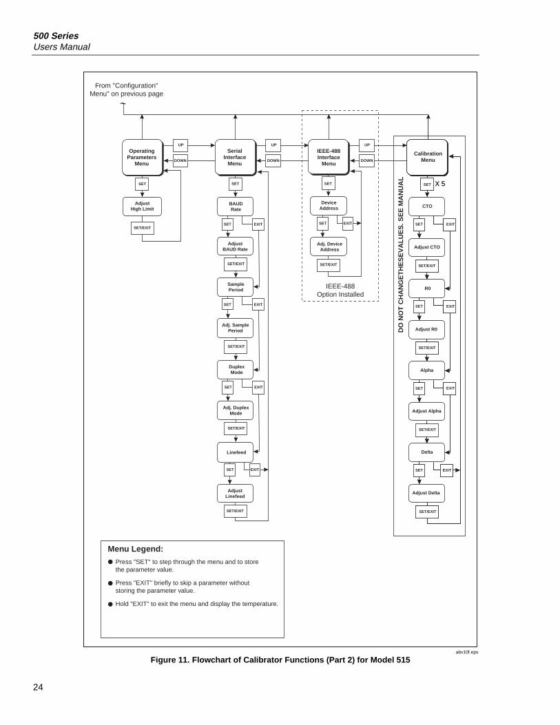
From "Configuration"Menu" on previous page
DeviceAddress
DuplexMode
Linefeed
AdjustLinefeed
AdjustHigh Limit
Menu Legend:
Press "SET" to step through the menu and to store the parameter value.
Press "EXIT" briefly to skip a parameter without storing the parameter value.
Hold "EXIT" to exit the menu and display the temperature.
DOWN
EXIT
EXIT
EXIT
Adjust CTO
Adjust R0
CTO
Alpha
Adj. DeviceAddress
OperatingParameters
Menu
UP
DOWN
UP
DOWN
SerialInterface
Menu
AdjustBAUD Rate
BAUDRate
SamplePeriod
Adj. DuplexMode
Adj. SamplePeriod
Adjust Delta
Delta
Adjust Alpha
DO
NO
T C
HA
NG
ET
HE
SE
VA
LUE
S. S
EE
MA
NU
AL
SET/EXIT
R0
SET/EXIT
abv10f.eps
Figure 11. Flowchart of Calibrator Functions (Part 2) for Model 515

Dry-Block CalibratorOperating the Calibrator
25
CTO518 hot side only
Adjust CTO518 hot side only
Adjust R0
Alpha
Delta
Adjust Alpha
Adjust Delta
SET/EXIT
UP
SET SET SET
EXIT
EXIT
EXIT
EXIT
EXITSET
SET
SET
SET
SET
SET/EXIT
X 5SET
EXIT
SET
SET
SET
SET
SET/EXIT
SET/EXIT
SET/EXIT
X 5
SET/EXIT
SET/EXIT
SET/EXIT
SET/EXIT
On coldside of
518
On bothsides of
518
To "Display Temperature"on previous pageFrom "Configuration"
Menu" on previous pageEXIT
DeviceAddress
AdjustBAUD Rate
DuplexMode
Linefeed
AdjustLinefeed
Beta (on 514, 517 and cold side of 518)
Adjust Beta (on 514, 517 and cold side of 518)
SET
SET/EXIT
Menu Legend:
Press "SET" to step through the menu and to store the parameter value.
Press "EXIT" briefly to skip a parameter without storing the parameter value.
Hold "EXIT" to exit the menu and display the temperature.
(Not available on 518)
OperatingParameters
Menu
AdjustHigh Limit
DOWN
UP
DOWN
UP
SerialInterface
Menu
BAUDRate
SampleRate
Adj. SampleRate
Adj. DuplexMode
IEEE-488Interface
Menu
Adj. DeviceAddress
IEEE-488Option Installed
CalibrationMenu
EXIT
SET/EXIT
EXIT
R0
EXIT
DO
NO
T C
HA
NG
E T
HE
SE
VA
LUE
S. S
EE
MA
NU
AL
DOWN
EXIT
abv11f.eps
Figure 12. Flowchart of Calibrator Functions (Part 2) for Models 514/517/518
500 SeriesUsers Manual
26
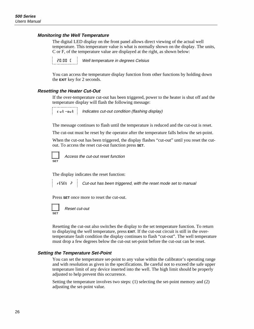
Monitoring the Well TemperatureThe digital LED display on the front panel allows direct viewing of the actual welltemperature. This temperature value is what is normally shown on the display. The units,C or F, of the temperature value are displayed at the right, as shown below:
20 . 00 C Well temperature in degrees Celsius
You can access the temperature display function from other functions by holding downthe EXIT key for 2 seconds.
Resetting the Heater Cut-OutIf the over-temperature cut-out has been triggered, power to the heater is shut off and thetemperature display will flash the following message:
cut_out Indicates cut-out condition (flashing display)
The message continues to flash until the temperature is reduced and the cut-out is reset.
The cut-out must be reset by the operator after the temperature falls below the set-point.
When the cut-out has been triggered, the display flashes “cut-out” until you reset the cut-out. To access the reset cut-out function press SET.
SET
Access the cut-out reset function
The display indicates the reset function:
r E S Et ? Cut-out has been triggered, with the reset mode set to manual
Press SET once more to reset the cut-out.
SET
Reset cut-out
Resetting the cut-out also switches the display to the set temperature function. To returnto displaying the well temperature, press EXIT. If the cut-out circuit is still in the over-temperature fault condition the display continues to flash “cut-out”. The well temperaturemust drop a few degrees below the cut-out set-point before the cut-out can be reset.
Setting the Temperature Set-PointYou can set the temperature set-point to any value within the calibrator’s operating rangeand with resolution as given in the specifications. Be careful not to exceed the safe uppertemperature limit of any device inserted into the well. The high limit should be properlyadjusted to help prevent this occurrence.
Setting the temperature involves two steps: (1) selecting the set-point memory and (2)adjusting the set-point value.

Dry-Block CalibratorOperating the Calibrator
27
Accessing the Programmable Set-PointsThe controller stores 8 set-point temperatures in memory. The set-points can be quicklyrecalled to set the calibrator to a previously programmed temperature.
To set the temperature, you must first select the set-point memory. This function isaccessed from the temperature display function by pressing SET. The number of the set-point memory currently being used is shown at the left on the display, followed by thecurrent set-point value.
20 . 00 C Well temperature in degrees Celsius
SET
Access set-point memory
1 . 20 . 0 Set-point memory 1 (20.0 °C) currently used
To change the set-point memory location, press UP or DOWN.
3 . _10 . 0 New set-point memory 3, –10.0 °C
Press SET to accept the new selection and access the set-point value.
SET
Accept selected set-point memory
Adjusting a Set-Point ValueThe set-point value may be adjusted after selecting the set-point memory and pressingSET. The set-point value is displayed with the units, C or F, at the left.
C _10 . 0 Set-point 3 value in °C
If the set-point value need not be changed then press EXIT to resume displaying the welltemperature. Press UP or DOWN to adjust the set-point value.
C _12 . 00 New set-point value
When the desired set-point value is reached, press SET to accept the new value and accessthe temperature scale units selection. If you press EXIT, any changes made to the set-pointare ignored.
SET
Accept new set-point value

500 SeriesUsers Manual
28
Temperature Scale UnitsYou can set the controller’s temperature scale units to degrees Celsius (°C) or Fahrenheit(°F). The units are used to display the well temperature and set-points.
After adjusting the set-point value, press SET to change display units.
SET
Access display units
Un = C Scale units currently selected
Press UP or DOWN to change the units.
Un = F New units selected
Setting a Scan RateThe scan rate can be set and enabled so that when the set-point is changed the dry-blockwill heat or cool at a specified rate (degrees per minute) until it reaches the new set-point.With the scan disabled, the dry-block will heat or cool at the maximum possible rate.
Enabling or Disabling ScanningThe scan is controlled with the scan on/off function that appears in the main menu afterthe set-point function.
Sc=0FF Model 518: Scan function off
ScAn=0FF Models 514, 515, and 517: Scan function off
Press UP or DOWN to toggle the scan on or off.
Sc=0n Model 518: Scan function on
ScAn=0n Models 514, 515, and 517: Scan function on
Press SET to accept the present setting and continue.
SET
Accept scan setting

Dry-Block CalibratorOperating the Calibrator
29
Scan RateThe next function in the main menu is the scan rate. On Models 514, 515, 517, and 518the scan rate can be set from 0.1 °C/min to 100 °C/min. The maximum scan rate islimited by the natural heating or cooling rate of the calibrator. This is often less than 100°C/min, especially when cooling.
The scan rate function appears in the main menu after the scan control function. The scanrate units are in degrees per minute (C or F depending on the selected units).
S r= 10 . 0 Scan rate in °C/min
Press UP or DOWN to change the scan rate.
S r= 2 . 0 New scan rate
Press SET to accept the new scan rate and continue.
SET
Accept the scan rate
Testing a Thermal SwitchThe calibrator has a switch test function that allows an external switch to freeze thedisplayed temperature and stop the set-point from scanning. This function is useful fortesting thermal switches. This section explains the switch test and provides an exampledescribing how to set up and use this feature.
Enabling the Switch TestTo enable the switch test feature, press UP when the temperature is displayed. The switchtest display shows the temperature on the right and the switch status on the left. Thestatus “c” means the switch is closed; “o” means the switch is open. The status flasheswhen the switch is active (opposite the normal position). When a new set-point isselected, the new status becomes the normal position.
103 . 5 C Well temperature in degrees Celsius
UP
Access switch test
c 103 . 5 Switch status and temperature (switch closed)
To return to the well temperature display, press DOWN.
Display HoldDisplay hold mode is active when the switch test and scan functions are enabled. Thismode automatically stores a new set-point when the thermal switch changes states.

500 SeriesUsers Manual
30
Switch WiringWire the thermal switch to the back of the calibrator at the two terminals labeled“DISPLAY HOLD”. You can connect the switch wires to the terminals either way.Internally, the black terminal connects to ground; the red terminal connects to +5 Vthrough a 100 kΩ resistor. The calibrator measures the voltage at the red terminal andinterprets +5 V as an open switch and 0 V as a closed switch.
Switch Test ExampleThis section describes how to set up and operate the calibrator for an example applicationof the switch test feature.
In this example, you have a thermal switch that is supposed to open at about 75 °C andclose at about 50 °C. You can use the switch test feature and the scan function to test theaccuracy and repeatability of the switch’s response. You can read measurements on thedisplay or, preferably, collect the data using a computer connected to the RS-232 port.
To set up the test, follow the steps below:
1. Connect the switch wires to the “DISPLAY HOLD” terminals on the back of thecalibrator. Place the switch in the well.
2. Enable the set-point scanning by setting the scan to “ON” in the primary menu (see“Enabling or Disabling Scanning”).
3. Set the scan rate to a low value, 1.0 °C/ min for example (see “Scan Rate”). If thescan rate is too high you may lose accuracy because of transient temperaturegradients. If the scan rate is too low the duration of the test may be longer thannecessary. You may need to experiment to find the best scan rate.
4. Set the first program set-point to a value above the expected upper switchtemperature, for example 90 °C.
5. Set the second program set-point to a value below the expected lower switchtemperature, for example 40 °C.
6. Collect data on a computer connected to the RS-232 port. Refer to “DigitalCommunications” for instructions on configuring the RS-232 communicationsinterface.
Ramp and Soak Program MenuThe ramp and soak program feature lets you program a number of temperature set-pointsand have the dry-block automatically cycle between the temperatures, holding at each fora specified length of time. You can select one of four different cycle functions.
The program parameter menu is accessed by pressing SET and then UP.
20 . 00C Well temperature
SET + UP
Access program menu
P r oG Flashes “ProG” for program menu; then enters the menu.

Dry-Block CalibratorOperating the Calibrator
31
Setting the Number of Program Set-pointsThe first parameter in the program menu is the number of set-points to cycle through.You can use up to 8 set-points in a ramp and soak program.
P n=8 Number of program set-points
Use the UP or DOWN buttons to change the number from 2 to 8.
P n=3 New number of program set-points
Press SET to continue. If you press EXIT, any changes made to the parameter to be ignored.
SET
Save new setting
Setting the Temperature Set-PointsThe next parameters are the program set-points.
1 25 . 0 First set-point
Use UP or DOWN to select any of the set-points.
3 10 . 0 Third set-point
Press SET to change the set-point.
C 10 . 00 Set-point value
Use UP and DOWN to change the set-point value.
C 13 . 50 New set-point value
Press SET to save the new set-point value.
The other set-points can also be set in the same manner. Once the set-points areprogrammed as desired press EXIT to continue.
EXIT
Continue to the next menu function

500 SeriesUsers Manual
32
Setting the Program Soak TimeThe next parameter in the program menu is the soak time. This is the time, in minutes, forwhich each of the program set-points is maintained (after settling) before proceeding tothe next set-point. The duration is counted from the time the temperature settles to withina specified stability. You can set the stability requirement in the parameter menu asexplained in “Setting the Calibrator’s Operating Parameters”. The default is ±0.1 °C.
Pt= 15 Soak time in minutes
Use UP or DOWN to change the time.
Pt= 5 New soak time
Press SET to continue.
SET
Save new setting
Selecting a Program Function ModeThe next parameter is the program function mode. There are four modes: (1) the programscans up (from set-point 1 to n) only, (2) the program scans both up and down (from set-point n to 1), (3) the program stops after one cycle, and (4) the program repeats the cycleindefinitely. Table 9 summarizes the four program mode settings.
Table 9. Ramp and Soak Program Modes
Function Action
1 up-stop
2 up-down-stop
3 up-repeat
4 up-down-repeat
P F= 1 Program mode
Use UP or DOWN to change the mode.
P F= 4 New mode
Press SET to continue.
SET
Save new setting

Dry-Block CalibratorSecondary Functions
33
Starting and Stopping the ProgramThe final parameter in the program menu is the control parameter. You may choose fromthree options: (1) start the program from the beginning, (2) continue the program fromwhere it was when it was stopped, (3) or stop the program.
P r=0F F Program presently off
Use UP or DOWN to change the status.
P r=StArt Start cycle from the beginning
Press SET to activate the new program control command and return to the temperaturedisplay.
SET
Activate the new command
Secondary FunctionsFunctions used less often are available in the secondary menu. You can access thesecondary menu by pressing SET and EXIT simultaneously and then releasing the buttons.The first function in the secondary menu is the heater power display.
Monitoring the Heating PowerThe temperature controller controls the temperature of the well by heating or cooling thewell with the thermoelectric modules or triacs (depending on the model). The amount ofheating or cooling power depends on the temperature set-point of the well. This heating(or cooling) power value may be estimated by watching the red/green LED or readdirectly from the digital display. By knowing the amount of heating, the user can tell ifthe calibrator is heating up to the set-point, cooling down, or maintaining a constanttemperature. The fluctuations in the heater power percentage represent the stability of thewell temperature. With good stability, the heating power percentage should not fluctuatemore than ±1 % within one minute.
The heater power display is accessed in the secondary menu. Press SET and EXIT
simultaneously, then release the buttons. The heater power is displayed as a percentage offull power.
20 . 00 C Well temperature
SET + EXIT
Access the heater power in the secondary menu
S EC Flashes “SEC” for secondary menu; then displays the heater power
_12 Pct Heater power in percent
For Models 514, 517, and the cold side of 518, negative numbers indicate the well isbeing cooled. Negative 100 % means the well is being cooled at maximum power. Zeropercent means the well requires neither heating nor cooling. One-hundred percent meansthe well is being heated at maximum power.

500 SeriesUsers Manual
34
For Model 515 and the hot side of 518, zero percent means maximum cooling (no heaterpower is applied). The power percentage is never negative for these models.
To exit out of the secondary menu press EXIT. To continue on to the proportional bandsetting function press SET.
Setting the Proportional BandIn a proportional controller such as this, the heater output power is proportional to thewell temperature over a limited range of temperatures around the set-point. This range oftemperature is called the proportional band. At the bottom of the proportional band theheating is 100 %. At the top of the proportional band the cooling is 100 %. Thus, as thetemperature rises the heater power is reduced, which tends to lower the temperature backdown. In this way, a fairly constant temperature is maintained.
The well’s temperature stability and response time depend on the width of theproportional band. See Figure 13. If the band is too wide the well temperature willdeviate excessively from the set-point due to varying external conditions. This is becausethe heater power changes very little with temperature and the controller cannot respondvery well to changing conditions or electrical or thermal noise in the system. If theproportional band is too narrow the temperature may swing back and forth because thecontroller overreacts to temperature variations. For best control stability the proportionalband must be set for the optimum width.
The proportional band width is set at the factory and printed on the Report of Calibrationincluded with all models. The proportional band width may be altered by the user if hedesires to optimize the control characteristics for a particular application.
The proportional band width is easily adjusted from the front panel. The width may be setto discrete values in degrees C or F depending on the selected units. The proportionalband adjustment is accessed within the secondary menu. Press SET and EXIT to enter thesecondary menu and show the heater power.
Proportional Band too Narrow Proportional Band too Wide
Optimum Proportional Band
abv02f.eps
Figure 13. Well Temperature Fluctuation at Various Proportional Band Settings

Dry-Block CalibratorSecondary Functions
35
SET + EXIT
Access the secondary menu
S EC Flashes “SEC” for secondary menu, then displays the heater power
_12 Pct Heater power in percent
SET
Access the proportional band setting
P r0P Model 518: Flashes “PrOP” for proportional band setting, then displaysthe setting
5 . 0 Model 518: Proportional band setting
Pb=523 C Models 514, 515, and 517: Proportional band setting
To change the proportional band press UP or DOWN.
7 . 0 New proportional band setting
To accept the new setting and continue, press SET. Pressing EXIT will exit the secondarymenu without making changes to the proportional band value.
SET
Accept the new proportional band setting
Configuring the Temperature ControllerThe calibrator’s temperature controller has a number of configuration and operatingoptions and calibration parameters that are programmable from the front panel. These areaccessed from the secondary menu. There are 4 sets of configuration parameters:operating parameters, serial interface parameters (if applicable), IEEE-488 interfaceparameters (if applicable), and controller calibration parameters. The menus are selectedusing UP and DOWN and then pressing SET.
Press SET to enter the configuration menu.
Con FiG? Flashes “ConFiG?” to designate the beginning of the menu

500 SeriesUsers Manual
36
Setting the High Limit ParametersUse the high limit parameter to adjust the upper set-point temperature, whichautomatically sets the soft cut-out. For safety, you can reduce the high limit parameter torestrict the maximum temperature set-point.
The high limit parameter is in the operating parameters menu, which is indicated by thefollowing:
PAr Operating parameters menu
Press SET to enter the menu.
Press SET again to enable adjustment of the high limit parameter.
H=126 Model 518: Current high limit setting
H L=126C Models 514, 515, and 517: Current high limit setting
Adjust the parameter using UP or DOWN.
H=90 Model 518: New high limit setting
H L=90C Models 514, 515, and 517: New high limit setting
Press SET to accept the new high limit parameter.
Serial Interface ParametersThe serial interface parameters menu controls the operation of the serial interface. Thesecontrols only apply to calibrators fitted with the serial interface. The parameters in themenu are baud rate, sample period, duplex mode, and linefeed. See “RS-232Communications” for instructions on using the serial interface.
IEEE-488 ParametersThe calibrator may optionally be fitted with an IEEE-488 GPIB interface. In this case theuser may set the interface address within the IEEE-488 parameter menu. This menu doesnot appear on instruments not fitted with the interface. See “IEEE-488 Communications”for instructions on using the IEEE-488 interface.

Dry-Block CalibratorMethods for Calibrating Probes
37
Calibration ParametersYou can access a number of the instrument calibration constants, such as CTO, RO,ALPHA, DELTA, and BETA (Models 514, 517, and 518). These values are set at thefactory and must not be altered. The correct values are important to the accuracy andproper and safe operation of the calibrator. Access to these parameters is available onlyso that if the controller’s memory fails, you can restore these values to the factorysettings. The report of calibration lists these constants and their settings.
CautionDo not change the values of the calibration constants from thefactory set values. The correct setting of these parameters isimportant for the safety and proper operation of the calibrator.
The calibration parameters menu is indicated by the following:
CAL Calibrations parameters menu
Press SET five times to enter the menu.
Parameter CTO sets the calibration of the over-temperature cut-out. This parameter isadjusted with an internal potentiometer only by qualified service technicians. For Models514 and 517, this parameter should read between 150 and 170. For Model 515, thisparameter should read between 610 and 630. For Model 518, the cold side does not havethe CTO parameter and the hot side should read between 680 and 690.
Methods for Calibrating ProbesFor optimum accuracy and stability, allow Models 514 or 517 to warm up for 10minutes after power-up. Allow Models 515 or 518 to warm up for 30 minutes. Afterwarm-up, allow adequate stabilization time after reaching the set-point temperature.After completing calibration, allow the block to cool before switching the power off.
For information on automating your testing, contact Fluke Corporation.
Direct CalibrationDirect calibration involves testing a probe directly against the dry-block’s temperaturedisplay. The method has the advantage of being quick and easy.
Insert the probe to be calibrated into the well of the dry-block calibrator. The probeshould fit snugly in the calibrator, yet should not be so tight that it cannot be easilyremoved. Remove any dirt or grit that may cause the probe to jam in the insert. For bestresults, insert the probe to the full depth of the well. Once the probe is inserted into thewell, allow adequate stabilization time to allow the test probe temperature to settle asdescribed. Once the probe has settled to the temperature of the well, it may be comparedto the calibrator display temperature. The display temperature should be stable to within0.1 °C for best results.
CautionNever allow foreign material into the probe holes. Fluids andother materials can damage the calibrator or cause binding anddamage to your probe.

500 SeriesUsers Manual
38
Comparison CalibrationComparison calibration involves testing a probe against a similar reference probe. Thismethod can be more accurate because errors due to dry-block tolerances, the stem effect,and temperature gradients are reduced.
After inserting the probes to be calibrated, allow sufficient time for the probes to settleand the temperature of the dry-block to stabilize.
Both the reference probe and the probe under test should be the same size andconstruction. Probes with different lengths, diameters and materials have different stemeffects, causing an unknown temperature difference. All dry-blocks have horizontal andvertical gradients that change with temperature. This is an unknown variable that can befactored out if probes are the same type, length, diameter, and material. Probes should beinserted to the same depth in the well.
Use the following procedure to calibrate a probe against a reference while eliminatingerror due to temperature gradients between wells.
1. Place the reference probe in one well.
2. Place the probe to be calibrated in another well.
3. After allowing the probe temperatures to settle, take a temperature reading from each.
4. Swap the locations of the reference probe and probe under test. Allow plenty of timefor thermal settling.
5. Make another set of temperature readings from the reference probe and the probeunder test.
6. Average the two readings of the reference probe. Average the two readings of theprobe under test. Averaging the two readings eliminates error due to temperaturegradients between the two wells.
7. You may now compare the averaged reading of the probe under test with theaveraged reading of the reference probe.
For best results repeat the test several times at the same temperature and at differenttemperatures.
You can use this method with different types of probes but you must determine theuncertainty of the measurement.
Calibrating Multiple ProbesFully loading the calibrator with probes increases the time required for the temperature tostabilize after inserting the probes. Be sure that the temperature has stabilized beforestarting the calibration.
You can calibrate multiple probes simultaneously by using either the direct orcomparison calibration method. Stem effect will cause less error in the comparisoncalibration method than with the direct calibration method.

Dry-Block CalibratorDry-Block Characteristics
39
Dry-Block CharacteristicsUnderstanding the thermal characteristics of the dry-block calibrator can help youachieve the best accuracy and efficiency possible.
Vertical GradientHeat losses from the top of the calibrator create a vertical temperature gradient in thewell. The heater has been applied to the block in a way that compensates for nominal heatlosses from the top of the dry-block and minimizes vertical temperature gradients.However, actual heat losses will vary depending on the number and types of probesinserted into the calibrator and the block temperature. For best results, insert probes thefull depth of well.
Stabilization and AccuracyThe stabilization time for the dry-block calibrator depends on the conditions andtemperatures involved. Table 5 near the beginning of this manual shows the heating andstabilization times for each model of the calibrator.
Another period of stabilization is required after a cold probe is inserted into a well. Thestabilization time depends on the magnitude of the thermal disturbance and the accuracyrequired. For example, a ¼ inch diameter room-temperature probe inserted into a 300 °Chole will take approximately 5 minutes to be within 0.1 °C of its set-point and will take10 minutes to achieve maximum stability.
You can decrease the calibration time by knowing how soon to make measurements.These times can be established by making typical measurements at the desiredtemperatures with the desired test probes.
Digital Communication InterfaceThe dry-block calibrator can communicate with and be controlled by other equipmentthrough the digital interface. You can use remote communications equipment to set theset-point temperature, monitor the temperature, and access any of the other controllerfunctions. Two types of digital interface are available: the RS-232 serial interface and theoptional IEEE-488 GPIB interface.
RS-232 CommunicationsThe calibrator is installed with an RS-232 serial interface that allows serial digitalcommunications over fairly long distances. With the serial interface the user may accessany of the functions, parameters and settings discussed under “Operating the Calibrator”,with the exception of the baud rate setting.
For Model 518, the baud rate, duplex made, and linefeed are set using the cold sidecommands (C:). The sample rate can be set for both the cold and hot side.
Cable Wiring and Data ProtocolThe serial communications cable attaches to the DB-9 connector at the back of thecalibrator.
Figure 14 shows the pin-out of this connector and suggested cable wiring. To eliminatenoise, the serial cable should be shielded with low resistance between the connector(DB9) and the shield.
The serial interface uses 8 data bits, one stop bit, and no parity.
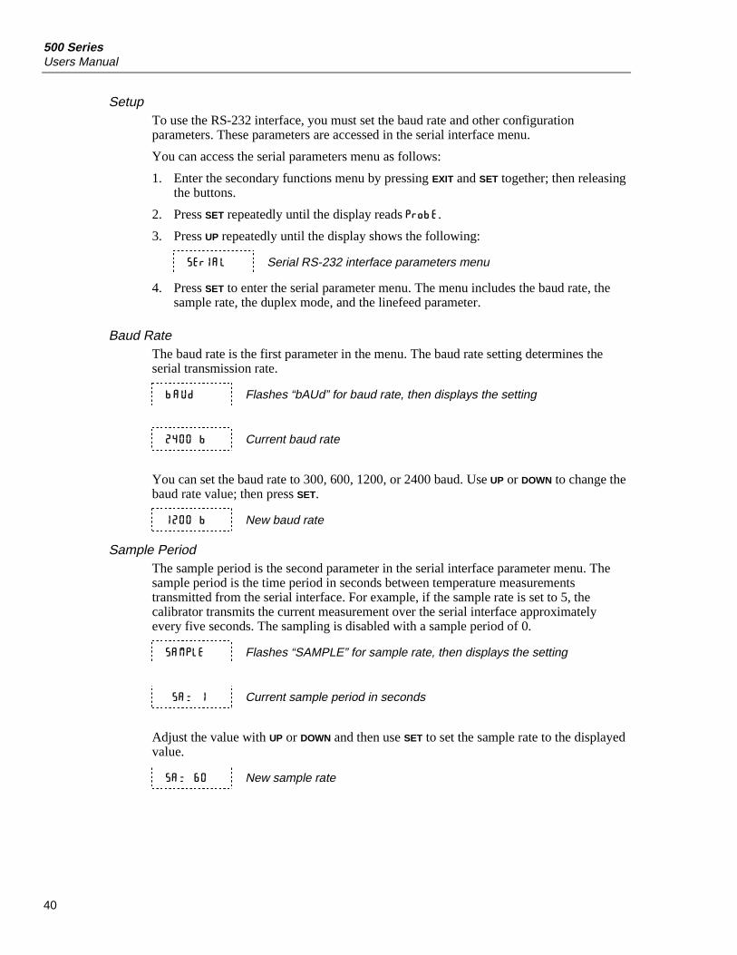
500 SeriesUsers Manual
40
SetupTo use the RS-232 interface, you must set the baud rate and other configurationparameters. These parameters are accessed in the serial interface menu.
You can access the serial parameters menu as follows:
1. Enter the secondary functions menu by pressing EXIT and SET together; then releasingthe buttons.
2. Press SET repeatedly until the display reads P r obE .
3. Press UP repeatedly until the display shows the following:
S E rIA L Serial RS-232 interface parameters menu
4. Press SET to enter the serial parameter menu. The menu includes the baud rate, thesample rate, the duplex mode, and the linefeed parameter.
Baud RateThe baud rate is the first parameter in the menu. The baud rate setting determines theserial transmission rate.
bAUd Flashes “bAUd” for baud rate, then displays the setting
2400 b Current baud rate
You can set the baud rate to 300, 600, 1200, or 2400 baud. Use UP or DOWN to change thebaud rate value; then press SET.
1200 b New baud rate
Sample PeriodThe sample period is the second parameter in the serial interface parameter menu. Thesample period is the time period in seconds between temperature measurementstransmitted from the serial interface. For example, if the sample rate is set to 5, thecalibrator transmits the current measurement over the serial interface approximatelyevery five seconds. The sampling is disabled with a sample period of 0.
SAMPL E Flashes “SAMPLE” for sample rate, then displays the setting
SA= 1 Current sample period in seconds
Adjust the value with UP or DOWN and then use SET to set the sample rate to the displayedvalue.
SA= 60 New sample rate

Dry-Block CalibratorDigital Communication Interface
41
1 NC2 RxD3 TxD4 NC5 GND6 NC7 RTS8 CTS9 NC
2 TxD3 RxD4 RTS5 CTS6 DSR7 GND8 DTD20 DTR
InstrumentConnector(DB 9-Pin)
Computer (DTE)Connector(DB 25-Pin)
1 NC2 RxD3 TxD4 NC5 GND6 NC7 RTS
8 CTS9 NC
1 DCD2 RxD3 TxD4 DTR5 GND6 DSR7 RTS
8 CTS9 NC
InstrumentConnector(DB 9-Pin)
Computer (DTE)Connector(DB 9-Pin)
RS-232 Cable Wiring forIBM PC and Compatibles
abv06f.eps
Figure 14. Serial Cable Wiring Diagram

500 SeriesUsers Manual
42
Duplex ModeThe third parameter is the duplex mode. The duplex mode may be set to full duplex orhalf duplex. With full duplex, any commands received by the calibrator through the serialinterface are immediately echoed or transmitted back to the device of origin. With halfduplex, the commands are executed but not echoed.
dUP L Flashes “dUPL” for duplex mode, then displays the setting
dUP=FU L Model 518: Current duplex mode setting (full duplex)
dUP=FU L L Models 514, 515, and 517: Current duplex mode setting (full duplex)
Use UP or DOWN to change the mode; then press SET.
dUP=HAL Model 518: New duplex mode setting (half duplex)
dUP=HAL F Models 514, 515, and 517: New duplex mode setting (half duplex)
LinefeedThe last parameter in the serial interface menu is the linefeed mode. This parameterenables (on) or disables (off) transmission of a linefeed character (LF, ASCII 10) aftertransmission of any carriage-return.
LF Flashes “LF” for linefeed, then displays the setting
LF=0 n Current linefeed setting (on)
Use UP or DOWN and to change the parameter; then press SET.
LF=0 F Model 518: New linefeed setting (off)
LF=0 FF Models 514, 515, and 517: New linefeed setting (off)
RS-232 OperationOnce you have attached the cable and properly set up the interface, the calibrator willimmediately begin transmitting temperature readings at the programmed rate. The set-point and other commands may be sent by a remote device to set the temperature set-point and view or program the various parameters. The interface commands are discussedunder “RS-232 and IEEE-488 Interface Commands”. All commands are ASCII characterstrings terminated with a carriage-return character (CR, ASCII 13).
IEEE-488 CommunicationsThe IEEE-488 interface is available as an option. Instruments supplied with this optionmay be connected to a GPIB type communication bus, which allows many instruments tobe connected and controlled simultaneously. To eliminate noise, the GPIB cable shouldbe shielded.
Dry-Block CalibratorDigital Communication Interface
43
SetupTo use the IEEE-488 interface first connect an IEEE-488 standard cable to the back ofthe calibrator. Next set the device address. This parameter is programmed within theIEEE-488 interface menu. (The IEEE-488 interface parameters menu is outlined in Table10.)
The menu is indicated by the following:
IEE E IEEE-488 parameters menu
Press SET to enter the menu.
IEEE-488 AddressThe IEEE-488 interface must be configured to use the same address as the externalcommunicating device. The address is indicated by the following:
Addr E S S IEEE-488 interface address
Press SET to access the address setting.
Add= 22 Current IEEE-488 interface address
Adjust the value with UP or DOWN and then use SET to set the address to the displayedvalue.
Add= 15 New IEEE-488 interface address
TerminationThe next parameter in the menu is the transmission termination character selection. Theparameter is indicated on the display by “EOS”. It can be set to carriage return only (Cr),linefeed only (LF), or carriage return and linefeed. Regardless of the option selected, theinstrument interprets either a carriage return or linefeed as a command termination duringreception.
IEEE-488 Operation for Models 514, 515, and 517Commands may now be sent via the IEEE-488 interface to read or set the temperature oraccess other controller functions. All commands are ASCII character strings and areterminated with a carriage-return (CR, ASCII 13). Interface commands are described inthe section “RS-232 and IEEE Interface Commands”.
IEEE-488 Operation for Model 518The IEEE-488 communication for Model 518 is managed by the calibrator’s serialconnection and converted to IEEE via an external conversion box. Cables are providedfor connection to a PC and to the instrument.
The IEEE converter box is configured at the factory and tested using IEEE address 22.Refer to the converter box manual, which is supplied with the box, for instructions onchanging this address.
Note that for Model 518, all commands should be proceeded by a “C:” for the cold sideor an “H:” for the hot side. Refer to Table 10 for a complete set of IEEE-488 commands.
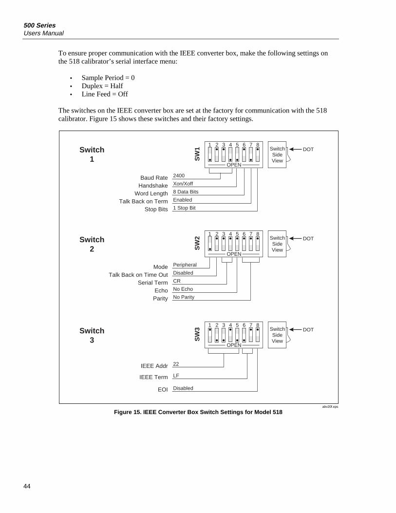
500 SeriesUsers Manual
44
To ensure proper communication with the IEEE converter box, make the following settings onthe 518 calibrator’s serial interface menu:
• Sample Period = 0• Duplex = Half• Line Feed = Off
The switches on the IEEE converter box are set at the factory for communication with the 518calibrator. Figure 15 shows these switches and their factory settings.
1 2 3 4 5 6 7 8
OPEN
SwitchSideView
DOT
SW
1
Baud RateHandshake
Word LengthTalk Back on Term
Stop Bits
2400
Xon/Xoff
8 Data Bits
Enabled
1 Stop Bit
1 2 3 4 5 6 7 8
OPEN
SwitchSideView
DOT
SW
2
ModeTalk Back on Time Out
Serial TermEcho
Parity
Peripheral
Disabled
CR
No Echo
No Parity
Switch1
Switch2
1 2 3 4 5 6 7 8
OPEN
SwitchSideView
DOT
SW
3
IEEE Addr
IEEE Term
EOI
22
LF
Disabled
Switch3
abv20f.eps
Figure 15. IEEE Converter Box Switch Settings for Model 518

Dry-Block CalibratorDigital Communication Interface
45
RS-232 and IEEE-488 Interface CommandsThe commands for accessing the calibrator functions via the digital interfaces are shownin Table 10.
These commands are used with both the RS-232 serial interface and the IEEE-488 GPIBinterface. In either case, the commands are terminated with a carriage-return character.
The interface makes no distinction between upper and lower case letters, hence eithermay be used. Commands may be abbreviated to the minimum number of letters thatdefines a unique command.
A command may be used to either set a parameter or display a parameter depending onwhether or not a “=” character followed by a value is sent with the command. Forexample “s”<CR> returns the current set-point and “s=50.00”<CR> sets the set-point to50.00 degrees.
In the following list of commands, characters or data within brackets, “[” and “]”, areoptional for the command. A slash, “/”, denotes alternate characters or data. Numericdata, denoted by “n”, may be entered in decimal or exponential notation.
Spaces may be added within command strings and will be ignored. Backspace (BS,ASCII 8) may be used to erase the previous character. A terminating CR is implied withall commands.
NoteFor Model 518, all commands are preceded by either a “C:” for cold or an“H:” for hot. If the “C:” or “H:” are not used with the command, thecommand accesses the cold side functions.

500 SeriesUsers Manual
46
Table 10. IEEE-488 Communication Commands
Command DescriptionCommand
FormatCommandExample Returned
ReturnedExample
AcceptableValues
Display Temperature
Read current set-point s[etpoint] s set: 9999.99C or F
set: 150.00 C
Set current set-point to n s[etpoint]=n s=450 InstrumentRange
Read temperature units u[nits] u u:C or F u:C
Set temperature units: u[nits]=c/f C or F
Set temperature unitsto Celsius
u[nits]=c u=c
Set temperature unitsto Fahrenheit
u[nits]=f u=f
Read scan function sc[an] sc scan:ON or OFF
scan: ON
Set scan function: sc[an]=on/of[f] ON or OFF
Turn scan function on sc[an]=on sc=on
Turn scan function off sc[an]=of[f] sc-of
Read scan rate sr[ate] sr srat: 999.99C or F/min
srat: 10.0C/min
Set scan rate to n degreesper minute
sr[ate]=n sr=5 .1 to 100°C
Read temperature t[emperature] t t: 9999.99C or F
t: 55.69 C
Read hold status ho[ld] ho ho:closed oropen,9999.9C or F
ho: open,75.0 C
Secondary Menu
Read proportional bandsetting
pr[op-band] pr pb: 999.99 pb: 15.9
Set proportional band to n pr[op-band]=n pr=8.83 Depends onConfiguration
Read heater power (duty cycle)
po[wer] po p%: 9999 po: 1

Dry-Block CalibratorDigital Communication Interface
47
Table 10. IEEE-488 Communication Commands (cont.)
Command DescriptionCommand
FormatComman
dExample
ReturnedReturnedExample
AcceptableValues
Ramp and Soak Menu
Read number ofprogrammable set-points
pn pn pn: 9 pn: 2
Set number of programmableset-points to n
pn=n pn=4 1 to 8
Read programmable set-pointnumber n
psn ps3 psn: 9999.99C or F
ps1: 50.00 C
Set programmable set-pointnumber n to n
psn=n ps3=50 1 to 8,Instrument
Range
Read program set-point soaktime
pt pt ti: 999 ti: 5
Set program set-point soaktime to n minutes
pt=n pt=5 0 to 500
Read program control mode pc pc prog: OFF orON
prog: OFF
Set program control mode: pc=g[o]/s[top]/c[ont] GO or STOPor CONT
Start program pc=g[o] pc=g
Stop program pc=s[top] pc=s
Continue program pc=c[ont] pc=c
Read program function pf pf pf: 9 pf: 3
Set program function to n pf=n pf=2 1 to 4
Configuration Menu
Serial Interface Menu
Read serial sample setting sa[mple] sa sa: 9 sa: 1
Set serial sampling setting ton seconds
sa[mple]=n sa=0 0 to 4000
Set serial duplex mode: du[plex]=f[ull]/h[alf] FULL orHALF
Set serial duplex mode tofull
du[plex]=f[ull] du=f
Set serial duplex mode tohalf
du[plex]=h[alf] du=h
Set serial linefeed mode: lf[eed]=on/of[f] ON or OFF
Set serial linefeed modeto on
lf[eed]=on lf=on
Set serial linefeed modeto off
lf[eed]=of[f] lf=of

500 SeriesUsers Manual
48
Table 10. IEEE-488 Communication Commands (cont.)
Command DescriptionCommand
FormatComman
dExample
ReturnedReturnedExample
AcceptableValues
Calibration Menu (WWarning: Changing the following calibration values may change the accuracy of the
calibrator.)
Read R0 calibrationparameter
r[0] r r0: 999.999 r0: 100.578
Set R0 calibration parameterto n
r[0]=n r=100.324 98.0 to 104.9
Read ALPHA calibrationparameter
al[pha] al al: 9.9999999 al: 0.0038573
Set ALPHA calibrationparameter to n
al[pha]=n al=0.0038433
.00370 to.00399
Read DELTA calibrationparameter
de[lta] de de: 9.99999 de: 1.46126
Set DELTA calibrationparameter to n
de[lta]=n de=1.45 0.0 to 2.9
Read BETA calibrationparameter
be[ta] be be: 9.999 be: 0.342
Set BETA calibrationparameter to n
be[ta]=n be=0.342 –100.0 to100.0
Miscellaneous (not onmenus)
Read firmware versionnumber
*ver[sion] *ver ver.9999,9.99 ver.514,1.00
Read structure of allcommands
h[elp] h list of commands
Legend: [] Optional Command data
/ Alternate characters or data
Returns either information
n Numeric data supplied by user—may be entered in decimal or exponential notation
9 Numeric data returned to user
x Character data returned to user
Note: When DUPLEX is set to FULL and a command is sent to READ, the command is returned followed by acarriage return and linefeed. Then the value is returned as indicated in the RETURNED column.

Dry-Block CalibratorCalibrating Models 514, 517, and 518 (cold side)
49
Calibrating Models 514, 517, and 518 (cold side)The dry-block calibrator should be calibrated at regularly scheduled intervals byqualified, authorized personnel in accordance with your company’s policy. Accuracyspecifications apply for a one-year calibration interval. Following is the recommendedcalibration procedure for Models 514 and 517 and the cold side of Model 518.
Calibration EquipmentCalibration requires a standard thermometer with acceptable accuracy that fits properlyinto one of the reference holes in the block. Recommended equipment includes alaboratory grade PRT (platinum resistance thermometer) with a length of 230 mm to300 mm (9 in to 12 in) and a diameter of 4.76 mm or 6.35 mm (3/16 in or 1/4 in). Thecombined accuracy of the PRT and the readout should be 0.025 °C or better.
Calibration ParametersThe calibration parameters for the calibrator’s RTD probe are in the secondary menu (seeFigure 11 or 12). The calibration menu is indicated by the following:
CAL Calibration menu
The calibration parameters are accessed by pressing SET after the name of the parameteris displayed. Use the UP and DOWN buttons to change the value of the parameter. PressSET to set the parameter to the new value. Pressing EXIT skips the parameter, ignoring anychanges that may have been made.
The calibration menu contains the following probe parameters:
R0
This probe parameter refers to the resistance of the RTD probe at 0 °C. The value of thisparameter is set at the factory for best accuracy.
ALPHAThis probe parameter refers to the average sensitivity of the RTD probe between 0 °C and100 °C. The value of this parameter is set at the factory for best accuracy.
DELTAThis parameter relates to the second-order nonlinearity of the sensor. The value is set atthe factory for best accuracy.
BETAThis parameter relates to the higher order nonlinearity of the sensor below 0 °C. Thevalue is set at the factory for best accuracy.

500 SeriesUsers Manual
50
Calibration ProcedureThe calibrator’s accuracy over the full range is determined by the values of thecalibration parameters R0, ALPHA, DELTA, and BETA. Refer to the Report ofCalibration shipped with you calibrator for the temperature range value.
The calibration procedure for Models 514 and 517 involves measuring the error betweenthe instrument and the reference thermometer at several temperatures throughout therange, then adjusting the calibration parameters as necessary to reduce the errors towithin acceptable limits. The stated accuracy of the instrument can be found in thespecifications (see Tables 2 through 4). Because of the way the calibration parametersaffect the temperature, the simplest way to proceed is to measure the errors at 0 °C, 100°C, 140 °C, and –25 °C and adjust R0, ALPHA, DELTA, and BETA at each pointrespectively. Follow these steps:
1. If “as found” data is required, then first measure the error at various temperaturesthroughout the range (for example –25 °C, 0 °C, 25 °C, 50 °C, 75 °C, 100 °C, and140 °C). Measure the errors by setting the controller to the desired temperature,allowing the block to reach the temperature and stabilize, then reading the actualtemperature of the block with the standard thermometer. If the measured errors are allwithin acceptable limits, no further action is required. If the accuracy needsimprovement, continue with Step 2.
2. Set the set-point to 0 °C and allow adequate time for the block to reach thistemperature and stabilize. Adjust the R0 calibration parameter to make the blocktemperature as measured with the standard thermometer match the set-point. Theapproximate ratio between a change in R0 and a change in temperature at 0 °C isabout 0.4 to 1. For example, if the block temperature is high by 0.1 °C at 0 °C thendecrease R0 by 0.04.
3. Set the set-point to 100 °C and allow adequate time for the block to reach thistemperature and stabilize. Adjust the ALPHA calibration parameter to make theblock temperature as measured with the standard thermometer match the set-point.The approximate ratio between a change in ALPHA and a change in temperature at100 °C is about 0.00004 to 1. For example, if the block temperature is high by 0.1 °Cat 100 °C then decrease ALPHA by 0.000004.
4. Set the set-point to 140 °C and allow adequate time for the block to reach thistemperature and stabilize. Adjust the DELTA calibration parameter to make theblock temperature as measured with the standard thermometer match the set-point.The approximate ratio between a change in DELTA and a change in temperature at140 °C is about -1.7 to 1. For example, if the block temperature is high by 0.1 °C at140 °C then increase DELTA by 0.17.
5. Set the set-point to –25 °C and allow adequate time for the block to reach thistemperature and stabilize. Adjust the BETA calibration parameter to make the blocktemperature as measured with the standard thermometer match the set-point. Theapproximate ratio between a change in BETA and a change in temperature at –25 °Cis about -50 to 1. For example, if the block temperature is high by 0.1 °C at –25 °Cthen increase BETA by 5.0.
6. Repeat Step 1 to ensure the calibrator is now accurate throughout the full range.

Dry-Block CalibratorCalibrating Models 515 and 518 (hot side)
51
Calibrating Models 515 and 518 (hot side)Model 515 and the hot side of Model 518 are calibrated by adjusting the controller probecalibration constants R0 and ALPHA so that the temperature of the dry-block asmeasured with a standard thermometer agrees more closely with the set-point. Thethermometer used must be able to measure the well temperature with higher accuracythan the desired accuracy of the dry-block calibrator. By using a good thermometer andcarefully following this procedure, the calibrator can be calibrated to an accuracy ofbetter than 0.5 °C over a range of 600 °C.
Calibration PointsAdjust R0 and ALPHA to minimize the set-point error at each of two different dry-blocktemperatures. Any two reasonably separated temperatures may be used for thecalibration. Refer to the Report of Calibration shipped with your calibrator for thetemperature values used. Improved results can be obtained for shorter ranges when usingtemperatures that are just within the most useful operating range of the dry-block. Thefarther apart the calibration temperatures, the larger the calibrated temperature range willbe, but the calibration error will also be greater over that range. If for instance 150 °C and500 °C are chosen as the calibration temperatures, then the calibrator may achieve anaccuracy of ±0.2 °C, for example, over the range 100 °C to 550 °C. Choosing 200 °Cand 300 °C may allow the calibrator to have a better accuracy of ±0.05 °C, for example,over the range 175 °C to 325 °C; however, outside that range, the accuracy may be only±0.4 °C.
Measuring the Set-point ErrorThe first step in the calibration procedure is to measure the temperature errors (includingsign) at the two calibration temperatures. First set the calibrator to the lower set-pointcalled tL. Wait for the well to reach the set-point and allow 30 to 60 minutes to stabilize atthat temperature. Check the stability with the thermometer. When both the well and thethermometer have stabilized, measure the temperature with the thermometer andcalculate the temperature error errL, which is the actual well temperature minus the set-point temperature. If, for example, the calibrator is set for a lower set-point oftL=200 °C and it reaches a measured temperature of 199.7 °C then the error is –0.3 °C.
Next, set the calibrator for the upper set-point tH. After stabilization, measure the welltemperature and calculate the error errH. For this example, suppose the calibrator was setfor 400 °C and the thermometer measured 400.1 °C giving an error of +0.1 °C.
500 SeriesUsers Manual
52
Computing R0 and ALPHABefore computing the new values for R0 and ALPHA, the current values must be known.The values may be found by either accessing the probe calibration menu from thecontroller panel or by inquiring through the serial interface. You should keep a record ofthese values in case they may need to be restored in the future. The new values R0′ andALPHA′ are calculated by entering the old values for R0 and ALPHA, the calibrationtemperature set-points tL and tH, and the temperature errors errL and errH into the followingequations:
RoALPHAtt
terrterrRo
LH
HLLH
+
−−= 1’
ALPHAtt
errt ALPHAerrt ALPHAALPHA
LH
HLLH
+
−+−+= 1
11 )()(’
If for example R0 and ALPHA were previously set for 100.2695 and 0.0038319respectively and the data for tL, tH, errL, and errH were as given above then the new valuesR0′ and ALPHA′ would be calculated as 100.193 and 0.0038272 respectively. Programthe new values R0 and ALPHA into the controller. Check the calibration by setting thetemperature to tL and tH and measuring the errors again. If desired, the calibrationprocedure may be repeated to further improve the accuracy.
Calibration ExampleThe calibrator will be used between 125 °C and 325 °C and maximum accuracy is desiredwithin this range. The current values for R0 and ALPHA are 100.000 and 0.0038500respectively. The calibration points are chosen to be 150.00 °C and 300.00 °C. Themeasured well temperatures are 149.943 °C and 299.814 °C respectively. Figure 16shows how to calculate the new probe constants for this example.
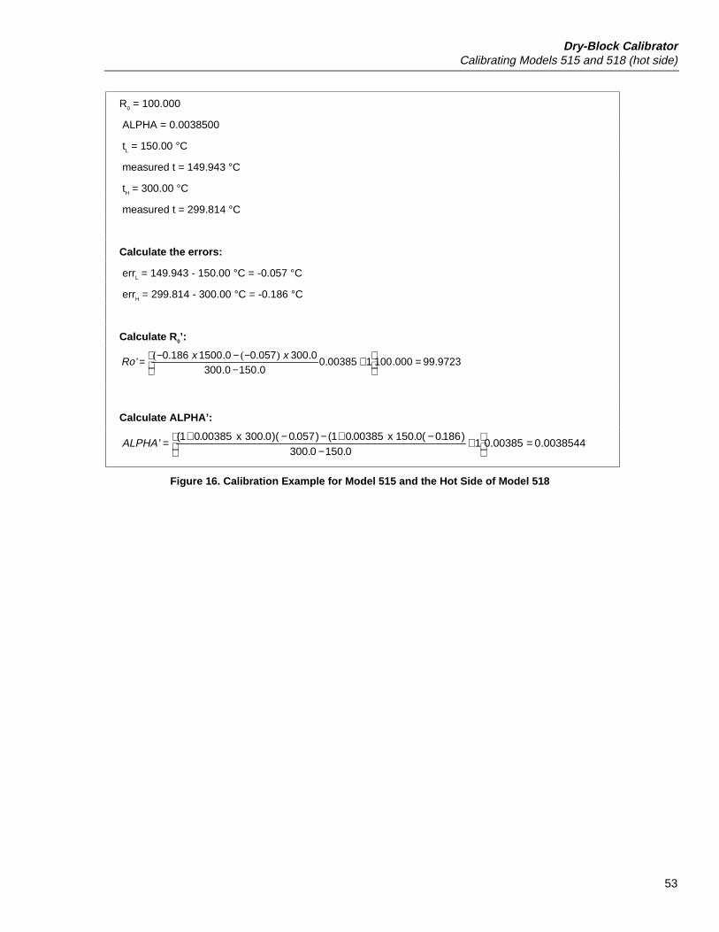
Dry-Block CalibratorCalibrating Models 515 and 518 (hot side)
53
R0 = 100.000
ALPHA = 0.0038500
tL = 150.00 °C
measured t = 149.943 °C
tH = 300.00 °C
measured t = 299.814 °C
Calculate the errors:
errL = 149.943 - 150.00 °C = -0.057 °C
errH = 299.814 - 300.00 °C = -0.186 °C
Calculate R0’:
972399000100100385001500300
03000570015001860...
..
.).(..( =
+
−−−−= x x
Ro’
Calculate ALPHA’:
0038544000385010.1500.300
)186.0(0.150 x 00385.01()057.0)(0.300 x 00385.01(.. =
+
−−+−−+=ALPHA’
Figure 16. Calibration Example for Model 515 and the Hot Side of Model 518

500 SeriesUsers Manual
54
Care and MaintenanceWith proper care the calibrator requires very little maintenance. The following guidelinesdescribe how to care for and maintain your calibrator.
• Avoid operating the instrument in an oily, wet, dirty, or dusty environment.
• If the outside of the calibrator becomes soiled, it may be wiped clean with a dampcloth and mild detergent. Do not use harsh chemicals on the surface because the paintmight be damaged.
• If the ac supply cord is damaged, replace it with a cord with the appropriate gaugewire for the calibrator’s current rating. If you have any questions, call FlukeCustomer Service for more information.
• Before using any cleaning or decontamination method except those recommended byFluke, check with Fluke Customer Service to be sure that the proposed method willnot damage the equipment.
• It is important to keep the well of the calibrator clean and clear of any foreign matter.DO NOT use fluid to clean out the well.
• The dry-block calibrator should be handled with care. Avoid knocking over ordropping the calibrator.
• For dry-blocks with removable inserts, the inserts can become covered with dust andcarbon material. If the buildup becomes too thick, it could cause the inserts tobecome jammed in the wells. Avoid this build up by periodically buffing the insertsclean with a Scotchbrite® fine-grit pad or an emery cloth.
• If an insert is dropped, examine it for deformities before inserting it in the well. Ifthere is any chance of the insert jamming in the well, file or grind off theprotuberance.
• DO NOT slam the probe stems into the well. Doing so can cause a shock to thesensor.
• If a hazardous material is spilt on or inside the equipment, you are responsible fortaking the appropriate decontamination steps as outlined by the national safetycouncil with respect to the material.
• If the instrument is used in a manner not in accordance with the equipment design,the calibrator may malfunction or safety hazards may arise.

Dry-Block CalibratorCare and Maintenance
55
Replacing the Fuses
WarningTo avoid electric shock, burns, or damage to equipment, alwaysreplace the fuses with ones of the correct rating, voltage, andtype.
1. Turn off the calibrator and unplug it from the ac outlet.
2. Replace the fuses as follows:
• For Models 514 and 518, unscrew the fuse holders on the back of the calibratorto access the fuses. Replace the fuses as necessary; then replace the fuse holders.
• For Models 515 and 517, insert a flat-blade screwdriver into the slot at the top ofthe power entry module (PEM) as shown in Figure 17. Gently open the moduleto access the fuse holder. Replace the fuses as necessary; then close the PEM
3. Connect the calibrator to the ac outlet.
515
Voltage window
517
abv18f.eps
Figure 17. Fuse Access for Models 515 and 517
TroubleshootingIf problems arise while operating the calibrator, refer to Table 11 for some suggestionsthat may help you solve the problem.

500 SeriesUsers Manual
56
Table 11. Troubleshooting the Calibrator
Incorrect temperature reading
Turn on the calibrator and watch the display. If the first number displayed is less than “-0005-”, the unithas been re-initialized. The unit needs to be reprogrammed for R0, ALPHA, DELTA, BETA, and theproportional band. These numbers can be found on the Report of Calibration that was shipped with theunit.
Display is off
• Check the fuses.
• Verify that the power cord is plugged in and connected to the unit.
The unit heats slowly
Check the Scan and Scan Rate settings. Scan may be on with the Scan Rate set to a low value.
An “o” or “c” is displayed at the left of the display
The external switch is open causing the displayed temperature to be frozen and keeping the set-pointfrom scanning. Turn the Switch Test off by pressing DOWN.
The display flashes “err 1” through “err 8”
Initialize the system by performing the master reset sequence (described below). If the unit repeats theerror code, contact Fluke Customer Support for a return authorization and for instructions on returningthe unit.
Master Reset Sequence
WCaution
The master reset sequence should be performed only by authorizedpersonnel if no other action is successful in correcting a malfunction. Youmust have a copy of the most recent Report of Calibration to restore thecalibration parameters.
To reset the unit, turn the unit off and back on. When all segments of the display light up ("8.8.8.8.8.8."on the display), during the power on sequence, immediately press and hold the SET and EXIT buttons.The display will indicate "-init-" and all parameters in memory will be cleared and set to the defaultvalues. Release the buttons to allow the power on sequence to complete. You must subsequentlyreprogram calibration parameters R0, ALPHA, DELTA, and BETA (if applicable) to ensure that the unitoperates with full accuracy. These numbers can be found on the Report of Calibration that was shippedwith the calibrator.
The display flashes “-273°C” or “-459°F”
The sensor is disconnected or shorted. Please contact Fluke Customer Support for further instructions.
The display flashes “cut-out”
The high limit is set too low. Check the high limit setting in the parameters menu.
The display shows “ICL” (518 only)
An intercommunication link error has occurred. The hot and cold sides were not turned on within 5seconds of each other. If RS-232 communication is not required for the hot side, press SET on both thehot and cold sides. If RS-232 communication is required, turn both sides off; then turn them both onwithin 5 seconds of each other.

Dry-Block CalibratorReplacement Parts
57
Replacement PartsTable 12 lists the replacement parts available from Fluke for the 500 Series Dry-BlockCalibrators. Inserts available for the calibrators are listed in Tables 6 through 8.
Table 12. Replacement Parts
Description Fluke Part Number Quantity
Filter-Fuse-Switch, 10 A 250 V, 517 1570686 1
Fuse, 4 A 250 V (115 V), 517 1570699 2
Output PCB, 517 1570702 1
Power Supply, 517 1570716 2
Power Supply, 20 W, 518 1577903 1
Power Supply, 150 W, 518 1577915 1
IEEE-488 PCB, 514, 515, 517 1570725 1
IEEE Converter Accessory, 518 1577892 1
Cooling Well Cover, 514, 517 1570733 1
Chassis Bail Handle Side, 514, 515, 517 1570740 2
Chassis Bail Handle, 514, 515, 517 1570757 1
Right Side Skin, 514, 515, 517 1570769 1
Left Side Skin, 514, 515, 517 1570778 1
Inner Wall, 517 1570784 1
Well Insulator, 517 1570791 2
Vented Well Cover, 518 1577814 1
Bottom Panel, 518 1577838 1
Front Panel, 518 1577845 1
Rear Panel, 518 1577850 1
Top Panel, 518 1577861 1
Right Side Panel, 4009, 518 1570804 1
Left Side Panel, 4009, 518 1570819 1
Well Cover, 515 1570828 1
Label, "Caution Hot Surface", 515, 518 1577877 1
Controller Front Panel Label, 4010, 514 1577926 1
Controller Front Panel Label, 4011, 517 1577932 1
Controller Front Panel Label, 4013, 515, 518 1577889 1
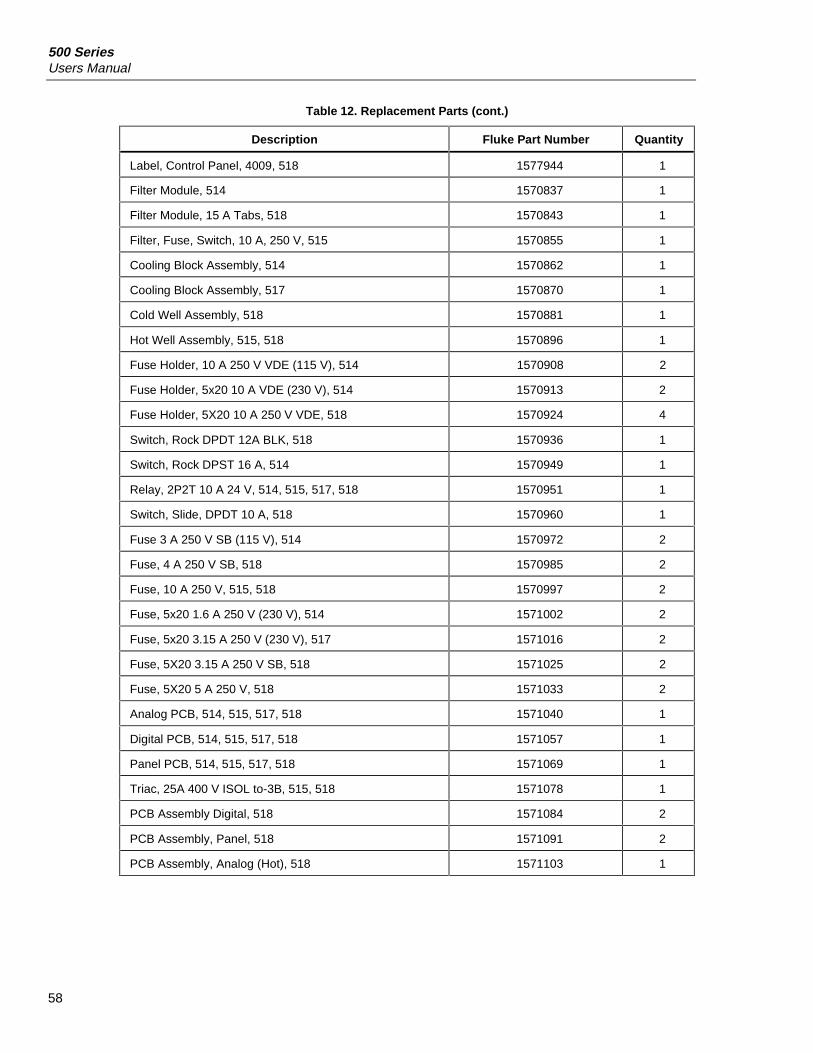
500 SeriesUsers Manual
58
Table 12. Replacement Parts (cont.)
Description Fluke Part Number Quantity
Label, Control Panel, 4009, 518 1577944 1
Filter Module, 514 1570837 1
Filter Module, 15 A Tabs, 518 1570843 1
Filter, Fuse, Switch, 10 A, 250 V, 515 1570855 1
Cooling Block Assembly, 514 1570862 1
Cooling Block Assembly, 517 1570870 1
Cold Well Assembly, 518 1570881 1
Hot Well Assembly, 515, 518 1570896 1
Fuse Holder, 10 A 250 V VDE (115 V), 514 1570908 2
Fuse Holder, 5x20 10 A VDE (230 V), 514 1570913 2
Fuse Holder, 5X20 10 A 250 V VDE, 518 1570924 4
Switch, Rock DPDT 12A BLK, 518 1570936 1
Switch, Rock DPST 16 A, 514 1570949 1
Relay, 2P2T 10 A 24 V, 514, 515, 517, 518 1570951 1
Switch, Slide, DPDT 10 A, 518 1570960 1
Fuse 3 A 250 V SB (115 V), 514 1570972 2
Fuse, 4 A 250 V SB, 518 1570985 2
Fuse, 10 A 250 V, 515, 518 1570997 2
Fuse, 5x20 1.6 A 250 V (230 V), 514 1571002 2
Fuse, 5x20 3.15 A 250 V (230 V), 517 1571016 2
Fuse, 5X20 3.15 A 250 V SB, 518 1571025 2
Fuse, 5X20 5 A 250 V, 518 1571033 2
Analog PCB, 514, 515, 517, 518 1571040 1
Digital PCB, 514, 515, 517, 518 1571057 1
Panel PCB, 514, 515, 517, 518 1571069 1
Triac, 25A 400 V ISOL to-3B, 515, 518 1571078 1
PCB Assembly Digital, 518 1571084 2
PCB Assembly, Panel, 518 1571091 2
PCB Assembly, Analog (Hot), 518 1571103 1
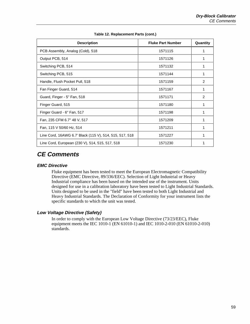
Dry-Block CalibratorCE Comments
59
Table 12. Replacement Parts (cont.)
Description Fluke Part Number Quantity
PCB Assembly, Analog (Cold), 518 1571115 1
Output PCB, 514 1571126 1
Switching PCB, 514 1571132 1
Switching PCB, 515 1571144 1
Handle, Flush Pocket Pull, 518 1571159 2
Fan Finger Guard, 514 1571167 1
Guard, Finger - 5" Fan, 518 1571171 2
Finger Guard, 515 1571180 1
Finger Guard - 6" Fan, 517 1571198 1
Fan, 235 CFM 6.7" 48 V, 517 1571209 1
Fan, 115 V 50/60 Hz, 514 1571211 1
Line Cord, 16AWG 6.7’ Black (115 V), 514, 515, 517, 518 1571227 1
Line Cord, European (230 V), 514, 515, 517, 518 1571230 1
CE Comments
EMC DirectiveFluke equipment has been tested to meet the European Electromagnetic CompatibilityDirective (EMC Directive, 89/336/EEC). Selection of Light Industrial or HeavyIndustrial compliance has been based on the intended use of the instrument. Unitsdesigned for use in a calibration laboratory have been tested to Light Industrial Standards.Units designed to be used in the "field" have been tested to both Light Industrial andHeavy Industrial Standards. The Declaration of Conformity for your instrument lists thespecific standards to which the unit was tested.
Low Voltage Directive (Safety)In order to comply with the European Low Voltage Directive (73/23/EEC), Flukeequipment meets the IEC 1010-1 (EN 61010-1) and IEC 1010-2-010 (EN 61010-2-010)standards.

500 SeriesUsers Manual
60


![Fluke 3000 FC Series Test Tools - Farnell · 2016. 5. 24. · 4 Fluke Corporation Fluke 3000 FC Series Test Tools. The Fluke Wireless Team. Frequency Range Resolution Accuracy [1]](https://img.pdfslide.us/doc/110x75/61189b840005cf1c4f4efcbe/fluke-3000-fc-series-test-tools-2016-5-24-4-fluke-corporation-fluke-3000.jpg)