Embed Size (px)
Citation preview
145
5.0 In-situ S/S equipment and its application
5.1 In-situ auger mixing
Auger mixing is the most widely used technique of in-situ soil mixing and is
especially useful for deeper applications, greater than 15 feet (4.6 m).
Auger mixing is suitable for a wide range of soil types to depths in excess of 100 ft
(30.8 m), although specialised methods are necessary for depths beyond 60 ft (18.5
m) below ground surface (BGS). Quality control is easier in comparison to all other
types of in-situ soil mixing (including e.g. rotary drum mixing and bucket mixing).
5.1.1 Equipment
Generally the equipment used for in-situ soil mixing consists of augers and their
support carriers to conduct the injection and mixing, a batch plant to prepare the
reagent slurry and pump it to the auger assembly, and miscellaneous support
equipment.
Figure 5.1: In-situ processes

146
Augers and their support carriers
There are two main types of drilling rigs used for in-situ soil mixing using an auger:
crane- and excavator-mounted units. Crane-mounted units consist of mechanically
driven rotary drilling heads fitted on a crawler crane. Excavator-mounted units
consist of hydraulically driven, rotary drilling heads fixed to an excavator base.
Crane-mounted units can generally accept slightly larger diameter augers (10-12 ft
or 3-3.6 m) and, in theory, have deeper mixing depth capabilities (by increasing the
amount of boom on the crane and installing a longer Kelly bar). On the other hand,
excavator-mounted rigs are generally best suited to smaller diameter augers (9-10 ft
or 2.8-3.1 m) and have stroke lengths limited to the mast height of the equipment
(generally less than ~60 ft or 18.5 m). However, recent advances in excavator-
mounted equipment have made these systems comparable and (in many ways)
more advantageous to use, than crane-mounted systems. This results from their
superior mobility, higher operating torque and lower mobilisation costs. Examples of
crane-mounted rigs are shown in Figures 5.2 and 5.3, while excavator mounted rigs
are shown in Figures 5.4 and 5.5.
The mixing head of the crane-mounted system is mechanically powered by an
engine/transmission combination, whereas the mixing head of the excavator-
mounted system is hydraulically powered using hydraulic pumps running off the
engine system of the host machine. Crane mounted systems generally have
maximum torque outputs (typically 250,000 – 350,000 ft-lbs or 34.56-48.39 kgf-m)
that far exceed the listed maximum torques of their excavator mounted counterparts
(typically 100,000 – 250,000 ft.lbs or 13.83-34.56 kgf-m). However, the operating
torque of crane-mounted systems is much less than the maximum torque, which is
only achieved during small portions of the engine power curve. Higher torque
requirements result in lower rotation speeds and therefore less thorough mixing. The
operating torque of excavator-mounted systems is very close to maximum available
torque and often exceeds the operating torque of much larger crane-mounted
systems. This allows higher rotation speeds at higher torque, resulting in a better
mixing.
147
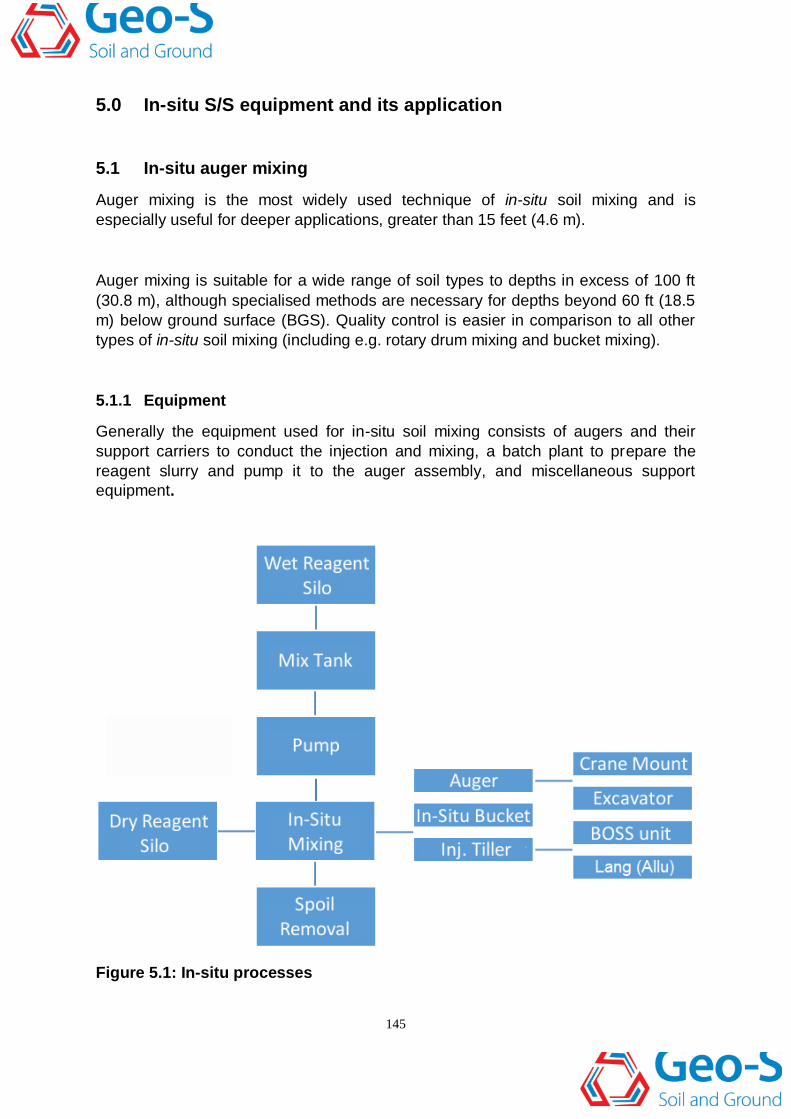
Figure 5.2: A crane-mounted soil-mixing rig
In both the crane and excavator-mounted systems, reagents are normally pumped
through a hollow Kelly bar and out of the auger ports. Reagents are most commonly
added in a liquid or grout form that acts as both the drilling lubricant and the final
stabilization reagent, but reagents can also be added in a dry-powder form.
Occasionally, for shallow/smaller applications, reagents are added at the surface, by
spreading.
Auger mixing provides the highest quality in-situ mixing available. The high torque
available in auger-mounted rigs makes them ideal for mixing dense sands and stiff
clays. A number of manufacturers produce drill rigs that can be used for soil mixing,
but most commercially available rigs require modification through additional specialty
equipment to be fully utilised in this application.
Auger mixing involving both crane and excavator mounted systems has been in use
for 25–30 years, however, in recent years the remediation industry has increasingly
tended to use excavator-based systems, due to their high level of mobility and
consistent torque output.

148
The actual soil cutting/mixing component, the auger bit, has been constructed in
many styles, though they all operate essentially the same. Figure 5.6 and Figure 5.7
illustrate two styles of auger bits. Both were used to complete in-situ auger treatment
on soils contaminated with coal tar wastes. Note that Figure 5.6 shows the use of
aiming stakes to locate column placement. This has largely been replaced by use of
very accurate GPS systems supplemented with depth control from a nearby survey
crew.
Figure 5.3: A crane-mounted soil-mixing rig
Figure 5.7 illustrates the auger often used today. In this case it is a 10ft diameter
auger and one can see the cutting teeth on the forward side of the blade and the
reagent injection ports on the trailing edge of the blade. Below the blade is a
projection, commonly called a “stinger” which helps guide the auger bit into the soil.

149
Batch plant equipment
Batching plants consisting of silos, pumps, and mixing tanks are critical to the
success of most in-situ soil mixing projects, relying on reagent delivery through ports
located on the mixing head of an auger. Batching plant configurations vary widely, as
their make-up/configuration includes the practitioner’s preference, reagent type and
quantity, the number of reagents to be used and the reagent pumping distance, and
site–related constraints.
For applications where the reagent(s) is being added as a grout, the batch plant can
become quite extensive. An example of an automated batch plant is shown in Figure
5.8.
The majority (>95%) of in-situ soil mixing projects use pre-mixed reagents in a fluid
grout or slurry form prior to injection. With the increased acceptance of this S/S
technology, it is not uncommon to blend two or three dry reagents in a batching plant
that is automated.
Figure 5.4: An excavator-mounted rig

150
Automated plants use weigh-scales to accurately measure mix components in a
process that improves efficiency and quality control.
For applications where the reagent is being delivered from dry, pressurised storage
tanks, pneumatic pumps are required. An example of a self-propelled dry pneumatic
reagent hopper is shown in Figure 5.9.
Ancillary equipment
In addition to the batching plant, a variety of ancillary support equipment is
necessary for the successful completion of an auger-based soil-mixing project. The
support equipment may include excavators, dozers, loaders, forklifts, man-lifts,
pumping systems, hoses, survey equipment and data loggers.
5.1.2 Staffing requirements
Typically an auger-based soil-mixing project requires a supervisor, drilling rig
operator and support labour, a batch plant operator and support labour, and
QC/engineering staff. However, staff requirements vary from project to project,
depending on ancillary work required and chosen batch plant configuration.
Figure 5.5: An excavator-mounted soil-mixing rig

151
Figure 5.6: Auger used at the USX Site, Duluth, MN
Figure 5.7: Auger used at a coal gas plant site in FL

152
Figure 5.8: An automated batch plant
5.1.3 Treatment metrics and considerations
The maximum treatment depth, the optimum auger diameter and reagent addition
methods and production rate are highly variable, depending on site-specific
conditions and the equipment employed. Obstructions in the sub-surface, such as
concrete slabs, pipes, rocks, and disused cables can substantially slow production,
break augers, and significantly increase cost. Such sub-surface objects should be
removed prior to starting auger-treatment to avoid potential costly delays. Additional
treatment metrics and considerations follow below.

153
Figure 5.9: Self-propelled dry storage silo
Depth of treatment
The depth of treatment is dependent on a number of factors, including soil-type and
relative density, the auger diameter and its configuration, the torque available to the
Kelly-bar, mast length and downward force capability (drill crowd and tool weight).
As previously mentioned, auger systems are generally limited to depths less than
60ft (18.46 m), unless specialty high-torque power units are used with smaller
diameter augers. Crane-mounted systems tend to have slightly deeper maximum
treatment depths, but mast extensions for excavator-mounted rigs are available to
match the depth capabilities of almost any crane-mounted unit.
Most of the excavator-based systems currently in use are limited to maximum depths
in the 45–55ft (14-17 m) range. It is important therefore, that practitioners should
comment on the depth limitations of their respective equipment in the soil conditions
anticipated at the project site. The effective maximum working depth can be derived
from geotechnical data, such as from CPTs, SPTs, and other common site
investigation-derived data. A decrease in the auger diameter (other factors being
equal) will generally allow for treatment at greater depth, however smaller augers
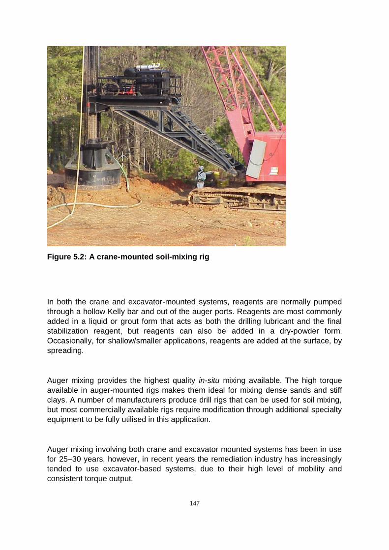
have a major adverse impact on production rates and cost. Table 5.1 lists some

154
remedial operations employing in-situ auger mixing, including the depth treated and
auger diameter employed.
Anticipated production rates
Generally, auger-based systems are capable of treating between 200-600 yd3 (153-
460 m3) of soil or sludge per working day (based on an 8 hour shift). However, this is
somewhat dependent on a variety of factors including relative soil geotechnical
properties, maximum treatment depth and reagent dosage, etc. At the optimum
production rate, with treatment depths of 10-40 ft and 8-10 ft diameter augers (3.1-
12.3 m and 2.5-3.1 m respectively), it is not unusual to treat over 800 yd3 (612 m3)
per auger in an 8-10 hour shift. However, due to maintenance requirements and the
occasional (expected) equipment breakdown, a lower average production rate
should be anticipated.
Reagent addition methods
Reagent addition is normally supplied by pumping/injecting through a wet Kelly-bar/
auger, or by adding the reagents at the soil surface (and then mixing in). However,
adding the reagents at the surface significantly limits the effective treatment depth
that can be achieved.
Reagent addition through the mixing tool provides improved delivery distribution and
therefore improved quality control by comparison. Depending on the equipment and
batch plant make-up, both dry and wet reagent addition are possible, with the former
being advantageous on projects with very high moisture content soils. Wet reagent
delivery is however, better for an even vertical reagent distribution within each S/S
column. Bench (Section 8.3) and pilot scale (Section 8.4) treatability tests are
critical for determining the appropriate reagent formula and field application methods.
5.1.4 Treatment plan
A site-specific and detailed treatment plan (otherwise known as a work-plan) is
produced by the contractor, prior to starting the remedial operation/treatment.
The treatment plan should include the specific equipment to be used, staffing,
proposed work schedule, reagent addition mixing and dosage rates and the plan for
sample collection/curing/testing, site safety and reporting requirements.
For in-situ auger mixing, a critical component of the plan is the precise layout and
planned depth of each column, so as to achieve the desired area of treatment with

155
overlapping columns. By employing overlapping columns, complete treatment is
achieved without leaving any untreated ‘void’ spaces.
The degree of overlap will vary depending on project-specific needs. Overlapping
columns will cause some portions of the soil to be mixed and treated two or possibly
three times. Increased overlapping will provide greater assurance that all the soil is
being treated, but in a slower production rate and at a higher treatment cost.
Figure 5.10 illustrates a portion of a typical column layout showing overlapping of
adjacent columns.
156
Table 5.1: Examples of in-situ auger treatments including auger diameter and depth treated
Site Name Constructor
Date
Completed
Auger
Diameter, Ft
(m)
Max. Depth,
Ft (m)
Volume
Treated, cy
(m3)
Considerations
Confidential Geo-
Solutions
Fall 2011 –
Spring 2012
10 (3) 41 (12.5) 58,000
(44,340)
Dense glacial till with
cobbles, high torque drill
Inner Slip Site Remediation Geo-
Solutions
Fall 2011 3 and 8 (0.9
and 2.4)
32 (9.7)
6,500
(4,970)
Loose dredge sediments,
tight access and poor
subgrade
SAR Levee Repair Geo-
Solutions
Fall 2010 9 (2.7) 54 (16.5) 5,500
(4,205)
High torque drill rig, dense
sandy soils
MW-520 Site Remediation Geo-
Solutions
Spring 2010 9 (2.7) 20 (6.1) 15,200
(11,620)
Clayey silts
Ameren Site Remediation Pilot
Study
Geo-
Solutions
Fall - Winter
2010
5 (1.5) 37 (11.3) 500 (382) Dense glacial tills, test
program (small volume)
Joachim Creek South Alignment
Bearing Capacity Improvement
Geo-
Solutions
Winter –
Spring 2010
9 (2.7) 40 (12.2) 2,500
(1,911)
High plasticity clay
OMC Plant 2 Site Remediation Geo-
Solutions
Fall –
Winter 2011
9 (2.7) 25 (7.6) 8,900
(6,805)
Dense sand & gravel
Former Municipal Wastewater
Treatment Lagoon Stabilization
Geo-
Solutions
Summer –
Fall 2012
8 (2.4) 26 (7.9) 8,600
(6,575)
Very dense clays
P&G Site Remediation Geo-
Solutions
Spring 2012 9 (2.7) 30 (9.1) 19,500
(14,910)
Lagoon sediments
Front and T Street Site
Remediation
Geo-
Solutions
Summer –
Fall 2012
10 (3) 33 (10) 40,000
(30,580)
High torque drill
Former Hanley Area Site
Remediation
Geo-
Solutions
Spring 2012 5 (1.5) 30 (9.1) 1,400
(1,070)
Tight access, small drill,
dry mixing

157
Figure 5.10: Typical column layout showing overlapping columns to achieve
100% coverage
For the constructor, over-lapped columns requires careful planning of the sequence
of column construction, as cutting into previously treated and solidified columns can
be difficult, if too much time has passed since initial treatment. A pragmatic approach
involves treating every other column, then returning and ‘cutting’ the skipped
overlapping columns on the second or third day. Figure 5.11 shows S/S columns that
have been excavated, illustrating that the overlapping of the columns facilitates the
complete treatment of the target interval.
5.1.5 Quality control
The level of quality control available for auger systems is very high in comparison to
other in-situ soil mixing methods. The quality control procedures available vary
based on the equipment being used, the reagent type (liquid or dry), and the
preference of the practitioner.

158
Table 5.2 gives key features of a typical quality control program from an auger-based
S/S mixing application.
Figure 5.11: showing typical excavated overlapping columns

159
Table 5.2: Quality control planning for auger-based S/S mixing
Quality Control Plan
Information Details
Lines of communication
Key personnel & responsibilities
Methods and procedures for
verifying reagent addition at
depth
Project staging Column layout showing 100% coverage of the
treatment area
Layout procedures GPS, Total Station, Triangulation
Sampling procedures
Non-conformance procedures
Daily monitoring requirements
Information Details
Grout consistency (wet
applications)
Density, Viscosity, Temperature, pH
Treated Columns
Dimensions (effective treated area & treated
depth)
Column centre-point locations
Unique column identification
Target reagent weight – based on effective
treated area & treated depth
Number of mixing strokes
Reagent Addition (dry and wet
applications)
Total volume of grout added via flow meter
(wet)
Weight of reagent via weigh-scales (dry)
Mixing energy
Rotary head (RPM)
Lift rate (if applicable)
Grout pressure/flow rate
Sample collection and curing
Information Details
Mold, store, transport, and testing
Completion of QC reports
Information Details
Daily Report
Daily report: site activities, problems, safety
issues, progress map (what has been
completed), total daily volume treated,
cumulative volume
Reagent Usage
QC report: reagent usage – total and per
treated volume, effective area calculations
(treated volume calculations), start stop time
Quality assurance of operational reporting by an independent engineer
160
5.1.6 Operational Issues
Equipment
The essential maintenance of equipment is an important part of the management of
any construction project, including S/S by in-situ soil mixing. Production can be
adversely affected by equipment that is poorly maintained and where wearable parts
are not regularly inspected and kept in an operational condition. Both the grout and
soils being treated are abrasive, and can have adverse effects on exposed portions
of the equipment, due to wear and chemical degradation.
The compatibility between the equipment being used and exposed to grout and site-
based contamination should be reviewed and a mitigation strategy implemented
where necessary.
Obstructions
Auger-based mixing equipment is sensitive to the presence of large sub-surface or
overhead obstructions. Given the deeper soil treatment depth-limitations of auger-
based systems, some obstructions can be too deep and too costly to effectively
remove.
Shallow obstructions are more easily dealt with when the treated soil is in a “liquid”
state, such as immediately after mixing. Site constraints may limit the removal of
obstructions during the mixing operation, and so the best approach might be to
stabilize all the soils around the obstruction and then remove the obstruction (from
between stabilized soils).
Spoil
In general, 15% to 30% of the volume of the treated soil becomes spoil, sometimes
called ’swell’, ‘slop’ or ‘float’. This spoil is formed above ground, as treated material,
which accumulates due to the mixing process and addition of reagents.
Above the water table some of the spoil becomes subsumed into the S/S column,
filling the pore spaces between soil particles. However, below the water table spoil is
displaced upwards to the surface of the column.
The spoil requires removal and/or disposal where possible. It generally has a high
slump value, being composed of soil, liquid grout, and groundwater. Spoils can be
moved and channelled in their liquid state or allowed to take an initial set, before
selective removal and transport/placement for disposal.

161
5.1.7 Summary of limitations, advantages, and disadvantages
In comparison to the other types of in-situ soil mixing, auger-mixing systems have
few limitations. All methods of in-situ soil mixing are heavily influenced by the
presence of sub-surface obstructions, and auger mixing of soil is no different.
Occasionally, a skilled operator can navigate the auger around small obstructions,
but in general, unforeseen sub-surface obstructions stop a soil-mixing project in its
tracks. Buried utility lines must be located and cleared if they are in the area to be
treated.
A rare exception to this is shown in Figure 5.12, which shows a 10 ft (3.1 m)
diameter in-situ auger treating soil immediately under an active fibre optic cable. The
fibre optic cables are located within the PVC pipes (just to the right of the Kelly bar)
and were temporarily exposed and supported while the auger bit was located
underneath the lines and then into the soil below.
Figure 5.13 is a video showing the mixing taking place in the location of the fibre
optic cable mentioned above.
Figure 5.12: In-situ treatment of soil under a live fibre optic line

162
Figure 5.13: In-situ mixing under fibre optic line
Auger mixing can be difficult in extremely dense soils or very ‘fat’ clays (liquid limit
greater than 50) as dense soils tend to cause accentuated wear of the mixing
equipment components and it’s difficult to achieve a consistent mix in ‘fat’ clays.
The advantages and disadvantages of auger mixing are summarised in Table 5.3.
5.1.8 Costs
Typical costs for stabilization using the auger mixing system are indicated below.
However, it should be noted that the costs involved are very sensitive to the depth of
treatment, the types of soils being treated, obstructions to mixing and the chemical
reagents being used. In addition, the specifics of performance sampling
requirements may also be important. As a rule of thumb, current prices for
mobilisation are $75,000 to $250,000, whereas the application of treatment is in the
range $30 to $60 / yd3 (0.7 m3) + reagent costs.
Table 5.3: Advantages and disadvantages of auger mixing
Advantages Disadvantages
High production rate/reduced schedule
time
Possible in difficult drilling conditions,
stiff clays / dense sands
Deeper depth capabilities
Treat below water table without
dewatering
Sensitive to obstructions
Requires specialty expertise and
equipment
Less efficient than other types of in-situ
or ex-situ mixing for shallow depths (<
5 ft)

163
5.2 Injection tillers and rotary drum mixers
Injection tillers and rotary drum mixers are suitable for the in-situ mixing of a wide
range of soil types to depths up to about 12 ft (3.7 m), although deeper mixing is
sometimes achievable in certain sludge-like materials.
For the purpose of clarity, injection tillers and rotary drum mixers are considered to
be an attachment to a standard excavator and can also be referred to as a Backhoe
Operated Soil Stabilizer, or BOSS unit. Quality control is limited in comparison to
auger mixing, but is better than that achieved with bucket mixing.
5.2.1 Equipment
Mixing equipment generally consists of some form of rotating mixing head through
which reagent is injected either dry, or more commonly, as grout slurry and mixed in
place at the target depth. In addition a batch plant is required to prepare the reagent
slurry according to the formula developed during bench scale treatability tests
(Section 8.3) and refined during the field pilot test (Section 8.4). Ancillary equipment
may include pumps, hoses, support excavators and/or front loaders, a dozer, and
survey equipment.
Mixing head types
In-situ soil mixing with injection tillers and rotary drum mixers is typically
accomplished using attachments to standard construction equipment, i.e.
excavators, dozers, and front-end loaders. Excavator “arm” attachments have the
greatest depth capabilities and are often referred to as BOSS systems for short.
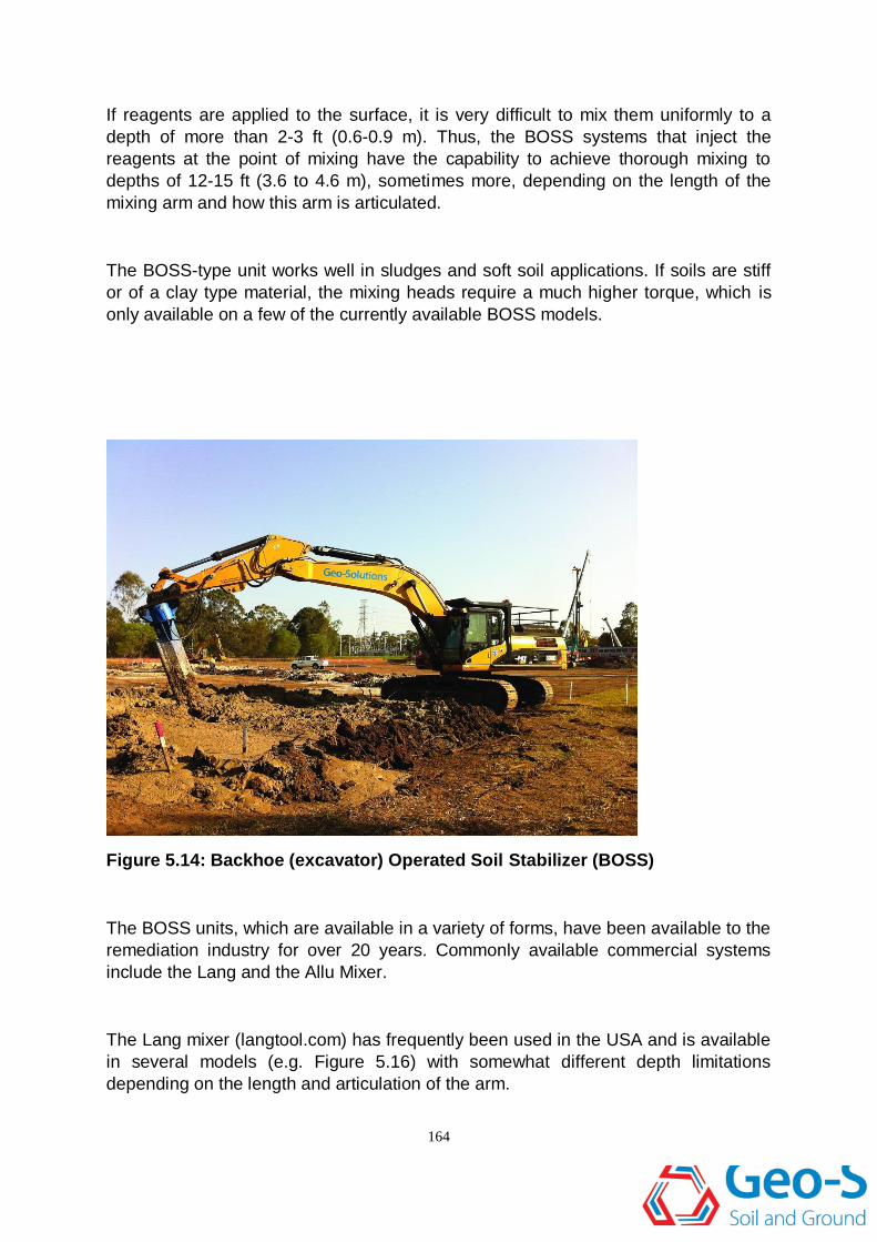
BOSS systems replace the digging bucket of an excavator assembly with a mixing
arm that has a rotary drum mixer at the end. Figures 5.14 and 5.15 show
commercially available BOSS systems used by Geo-Solutions.
With a BOSS system, the mixing head(s) is powered by the hydraulic system of the
host machine, or a separate hydraulic power pack can be mounted on the host
machine. Reagents may be pumped through the mixing arm or added at the surface.
Most of the BOSS units have the capability of pumping reagents through piping
which discharges just above the mixing head and this is of critical importance if
mixing to depths of more than 2-3 ft (0.6-0.9 m) is required.
164
If reagents are applied to the surface, it is very difficult to mix them uniformly to a
depth of more than 2-3 ft (0.6-0.9 m). Thus, the BOSS systems that inject the
reagents at the point of mixing have the capability to achieve thorough mixing to
depths of 12-15 ft (3.6 to 4.6 m), sometimes more, depending on the length of the
mixing arm and how this arm is articulated.
The BOSS-type unit works well in sludges and soft soil applications. If soils are stiff
or of a clay type material, the mixing heads require a much higher torque, which is
only available on a few of the currently available BOSS models.
Figure 5.14: Backhoe (excavator) Operated Soil Stabilizer (BOSS)
The BOSS units, which are available in a variety of forms, have been available to the
remediation industry for over 20 years. Commonly available commercial systems
include the Lang and the Allu Mixer.
The Lang mixer (langtool.com) has frequently been used in the USA and is available
in several models (e.g. Figure 5.16) with somewhat different depth limitations
depending on the length and articulation of the arm.

165
Figure 5.15: Backhoe (excavator) operated soil stabilizer
Figure 5.16 Lang mixer- excavator, arm, and mixing head as one unit

166
Reagent is injected just above the mixing head, which is sealed and custom fitted to
the excavator body, in one complete unit. This facilitates mixing in wet soil.
The Allu mixer (allu.net) has been less available in the USA. The Allu mixer is
provided as an attachment to be placed on a standard excavator body. Several
models with varying depth capability are available. However in the model recently
used on a coal tar site in Florida, it was observed that the top of the Allu attachment
was not sealed and thus could not be immersed in the treated soil. Figure 5.17
illustrates one model of the Allu mixer.
Batch plant equipment
Batch plants consisting of silos, pumps, and mixing tanks are critical to the success
of most in-situ soil mixing projects, namely those relying on reagent delivery through
ports at the mixing head such as the BOSS systems.
Batch plant configurations vary widely, due to plant makeup and configuration
and the practitioner’s preference. The type and quantity of reagents, as well
as the pumping distance and site constraints are also important. Where the
reagent is being added as a grout, the batch plant can be extensive. An
example of a large soil-mixing grout production plant is shown in Figure 5.18.
When the reagent is being delivered as a dry powder, pressurised storage
tanks and pneumatic conveyance pumps are required. An example of a self-
propelled dry pneumatic hopper is provided in Figure 5.9.
Ancillary equipment
In addition to the batch plant, a variety of support equipment is necessary for the
successful completion of a soil-mixing project using the BOSS system. Supporting
ancillary equipment may include excavators, dozers, loaders, forklifts, man-lifts,
hoses, pumps and surveying apparatus.
5.2.2 Staffing requirements
Typically a rotary drum mixing or injection tilling remedial project requires a
supervisor, mixing apparatus operator, mixing apparatus support labourer, batch
plant operator, batch plant support labourer, and QC/engineering staff. Labour

167
requirements vary from project to project depending on ancillary work and batch
plant configurations.
5.2.3 Treatment metrics and considerations
Some treatment metrics and considerations are briefly discussed below. However, in
practice these are very site- and equipment-specific, and the reader should consult
with an experienced practitioner regarding the application to any specific site.
Treatment Depth
As previously discussed, rotary drum mixers and BOSS systems are typically limited
to depths shallower than about 12-15 ft (3.69-4.62 m). Applications of this technology
to depths 15 ft (4.62 m) or deeper are possible, but mixing quality and quality control
become limited at increased depth. Note however that equipment designs and
capabilities are evolving and newer equipment may achieve good mixing at greater
depths. Practitioners should prepare and submit “digging” charts to illustrate the full
extent of their equipment’s capabilities, i.e. maximum treatment depth in relation to
the machine body.
Figure 5.17: Allu mixer head (in red) attached to a standard excavator
168
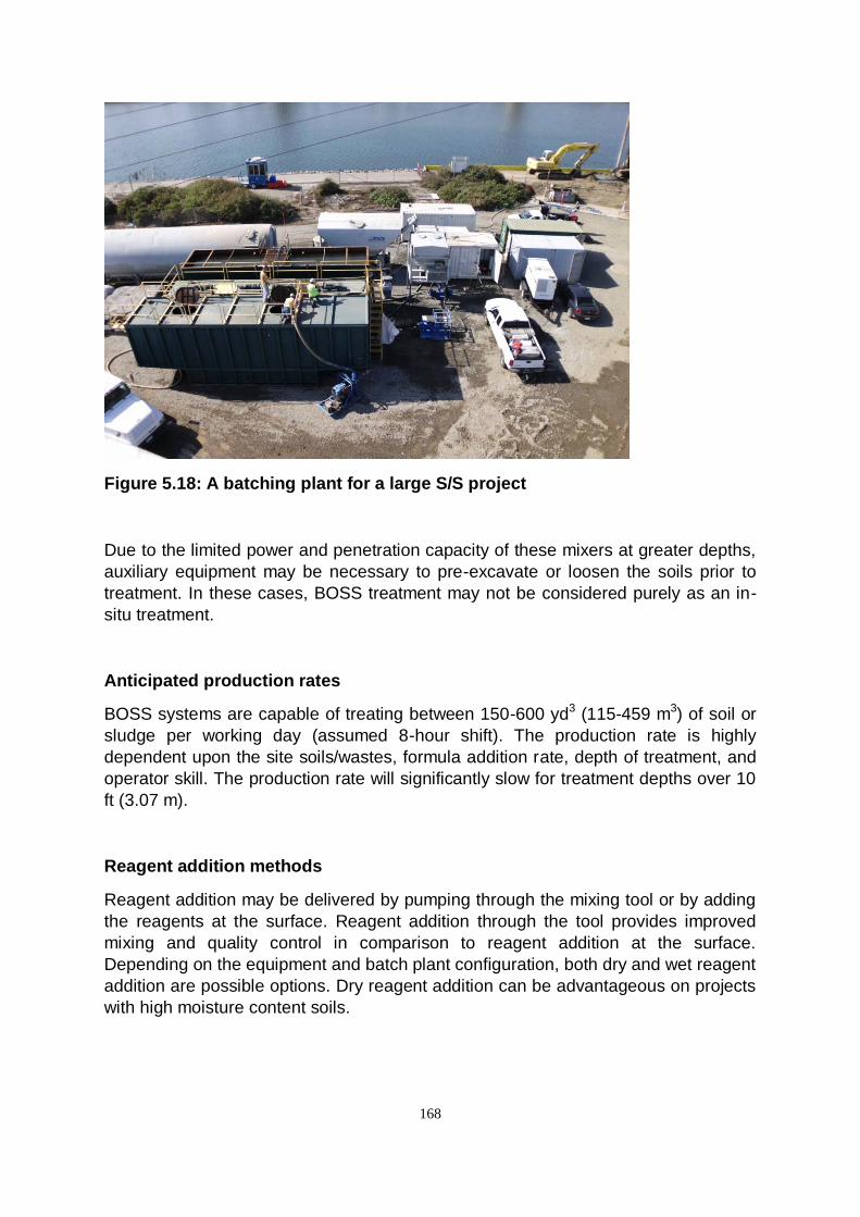
Figure 5.18: A batching plant for a large S/S project
Due to the limited power and penetration capacity of these mixers at greater depths,
auxiliary equipment may be necessary to pre-excavate or loosen the soils prior to
treatment. In these cases, BOSS treatment may not be considered purely as an in-
situ treatment.
Anticipated production rates
BOSS systems are capable of treating between 150-600 yd3 (115-459 m3) of soil or
sludge per working day (assumed 8-hour shift). The production rate is highly
dependent upon the site soils/wastes, formula addition rate, depth of treatment, and
operator skill. The production rate will significantly slow for treatment depths over 10
ft (3.07 m).
Reagent addition methods
Reagent addition may be delivered by pumping through the mixing tool or by adding
the reagents at the surface. Reagent addition through the tool provides improved
mixing and quality control in comparison to reagent addition at the surface.
Depending on the equipment and batch plant configuration, both dry and wet reagent
addition are possible options. Dry reagent addition can be advantageous on projects
with high moisture content soils.

169
Pre-construction investigations
Prior to commencement of field operations, it is important to thoroughly investigate
and delineate the treatment area and depth of treatment. Bench scale studies
(Section 8.3) are usually employed to determine efficient (or worst case) reagent
application rates and the mode of reagent delivery (grout or dry powder). In addition,
bench scale studies can be used to estimate spoil volume. Generally pilot-scale field
tests are conducted to refine the reagent dosage and the planning for execution of
the desired treatment option at full-scale.
5.2.4 Quality control
The level of quality control for BOSS systems is much less than that available on the
auger-based soil mixing systems. The quality control available for BOSS systems
varies based on the equipment used and the method of reagent delivery (wet or dry).
The components typical of a quality control program on a BOSS application are
given in Table 5.4.
For all in-situ S/S treatments, performance samples are collected and cured in a
similar manner to that described in Sections 6.2 and 6.3.
The correct care and attention should be given to sample storage and transportation
of quality control samples, which should be stored in a temperature-controlled
environment. During storage, samples should not be subjected to movement or
vibration, particularly during the initial 24 to 72 hours when undergoing initial set.
Samples should not be transported until they have initially set and achieved a
reasonable strength, usually within the period 3 to 7 days. When being shipped by
courier, samples should be properly packed to minimise movement and damage
during transportation.

170
Table 5.4: Quality control planning for BOSS-based S/S mixing
Quality Control Plan
Information Details
Lines of communication
Key personnel &
responsibilities
Lines of communication
Methods and procedures for
verifying reagent addition at
depth
If available, GPS can be used to assist the operator in
verifying complete mixing of the entire treatment block
Project staging
Grid map or daily treatment area.
Development of a grid to determine reagent application
zones. Each zone should be sized for a proportion of the
treatment area that can be completed in a few hours
(certainly less than 1 day).
Layout procedures GPS, Total Station, Triangulation
Sampling procedures
Non-conformance
procedures
Daily monitoring requirements
Information Details
Grout consistency (wet
applications)
Density, Viscosity, Temperature, pH
Treated panel or volume per
‘stroke’
Dimensions (length, width, depth)
Location
Unique identification
Target reagent weight
Number of mixing strokes
Reagent Addition (dry and
wet applications)
Total volume of grout added via flow meter (wet)
Weight of reagent via weigh-scales (dry)
Mixing energy
Rotary drum (RPM)
Lift rate (if applicable)
Grout pressure/flow rate
Sample collection and
curing
Information Details
Mold, store, transport, and
testing
Completion of QC reports
Information Details
Daily Reporting
Daily reporting of site activities, problems, safety issues,
progress map (what has been completed), total and
cumulative volume treated
Reagent Usage
QC reporting of reagent usage (total/per treated volume,
effective area calculations (treated volume calculations),
start stop times etc.
Quality assurance reporting by Independent engineer

171
5.2.5 Operational issues
Equipment
Equipment maintenance procedures are an important part of every construction
project, but can be especially important on in-situ soil mixing projects. Rotary drum
mixers have a limited mixing depth due to the equipment configuration, being
constrained by the length of the mixing arm.
Mixing at extended depth requires that the entire mixing arm, machine joint, and
machine boom are beneath the soil/sludge surface, and the grout and soil
undergoing mixing can have adverse effects on mechanical joints leading to
excessive equipment downtime and additional maintenance requirements.
Obstructions
The configuration of mixing arms allows them to more easily move around
obstructions than an auger-based unit, but they are still limited by the presence of
sub-surface and overhead obstructions. Given the shallow soil treatment limitations,
most obstructions in these applications can be easily removed using a support
excavator.
Obstructions are more easily removed when the treated soil is in a “liquid” state
immediately after mixing. Site constraints may, however, limit removal of
obstructions during the mixing operation. The best approach is then to stabilize all
the soil around the known ‘obstruction’ and then remove this by excavation between
stabilized soil-units.
Spoil
In general, 15% to 30% of the treated soil volume becomes spoil due to bulking by
the addition of reagents and the mixing process. The spoil materials require handling
and/or disposal by channelling whilst in their liquid state or after an initial set, when
they can be treated and disposed of as a soil.
5.2.6 Advantages and disadvantages of rotary tillers and injection drum
mixers
The advantages of rotary tillers and injection drum mixers are listed in Table 5.5.

172
Table 5.5: Advantages and disadvantages of rotary tillers and drum mixers
Advantages Disadvantages
Lower cost than auger mixing
High production rate
Reduced schedule
Can readily utilise reagent in a wet
(grout) or dry state
Reagent injection can be applied just
above the mixing drum(s)
Limited to a maximum depth of about
15 ft (4.62 m) below the working
surface
Applicable only in sludge or soft soils
Reduced level of quality control in
comparison with auger mixing
Obstructions require removal for
complete mixing
5.2.7 Costs
The costs of treatment with the BOSS system are very sensitive to the depth of
treatment desired, the soils being mixed and the reagents being used. As a guide,
current prices for BOSS mobilisation are $50,000 to $150,000, whereas the
application of treatment is in the range $15 to $30 / yd3 (0.7 m3), excluding reagent
costs.
5.3 In-situ bucket mixing
In-situ bucket mixing (excavator mixing) refers to using a standard excavator that
may have an extended reach, and an excavator bucket to mix reagents into the soil
in place.
Reagents may be added dry or as a slurry, but the effective depth for mixing is
however quite limited compared to other options. This approach to mixing is the
simplest form (in terms of equipment) of in-situ S/S treatment and has been
successfully used for decades. A video clip showing in-situ bucket mixing can be
viewed at http://youtu.be/bUFg2siBXd4
5.3.1 Equipment
Bucket mixing is generally carried out with excavators and standard excavation
buckets or specialty buckets (see Figure 5.19) designed to facilitate high slump soil
mixing. Shallow (1-2 ft or 0.3-0.6 m) mixing applications may be completed with bull-
dozers or front-loaders, but this application is uncommon and is limited.

173
Although the equipment used is universally available, it should not be assumed that
anyone with an excavator can successfully accomplish in-situ bucket treatment. The
mixing techniques require experience and the quality control needs are rigorous.
Figure 5.19: Example of bucket mixing
Ancillary Equipment - A variety of support equipment is necessary for the
successful completion of a soil-mixing project utilising bucket mixing. Support
equipment may include excavators, dozers, loaders, forklifts, man-lifts, etc. If
reagents are added as slurry, then a batch plant like that used for in-situ auger or
BOSS mixing will be required. Whether reagents are added dry or as slurry,
equipment is required to accurately measure reagent addition per unit of soil.
5.3.2 Staffing requirements
Typically a soil mixing project completed using bucket mixing requires a supervisor,
mixing excavator operator, mixing excavator support labour, and QC/engineering
staff. Labour requirements vary from project to project depending on ancillary work
and reagent addition procedures.
174
5.3.3 Treatment metrics and considerations
Treatment depth
Bucket mixing is limited to treatment depths less than 8 ft (2.5 m), as the uniform
mixing of surface-added reagents beyond this then becomes progressively more
difficult to achieve. However in some cases, bucket mixing may be extended to
about 15-20 ft (4.6-6.2 m) if specific procedures are carefully followed:
The first 5-6 ft (1.5-1.8 m) are initially mixed uniformly with reagent slurry. It is
necessary that the treated soil have a high slump. The excavator then carefully
removes several buckets of soil from below the previously mixed and slurried soil,
depositing the fresh soil above that previously mixed, and then proceeds to uniformly
mix this soil whilst adding fresh reagent. The void created by excavating below the
previously mixed soil is immediately filled by the mixed soil-slurry. This process is
repeated as necessary. Due to restrictions on excavator reach, often a portion of the
targeted cell is mixed to full depth, then the excavator re-positioned to mix another
vertical slice.
This technique will not work with all soils/sludges and requires constant quality
control monitoring to assure that the treated soils are homogenously mixed with
reagent. Quality control is already challenging with bucket mixing and even more so
at greater depth. Figure 5.20 depicts successful bucket mixing of coal tar
contaminated soil to a depth of about 15 ft (4.6 m). Note that the picture shows
clumps of deeper soil excavated to the surface, but not yet mixed so as to be
homogenous. Part of the quality control process is to frequently extract an excavator
bucket of mixed material from various depths, and visually check for clumps of
unmixed soil.
Anticipated production rates
It’s possible to treat 200-700 yd3 (153-536 m3) of soil per working day using in-situ
bucket mixing (assumed 8-hour shift). However this is very site-specific depending
on soil type, equipment, depth, and operator skill. Bucket mixing can often break up
and treat clays and other hard soils that are difficult to treat with BOSS systems.
Reagent addition methods
Pumping through the mixing head is not possible in soil mixing completed using
bucket mixing. Reagents are typically spread over the surface of the mixing area
and mixed into the soils as the bucket mixes the soils. Reagents may be added dry
or as a slurry.

175
Spoil
As with other in-situ treatment methods, a significant soil bulking may take place and
a large amount of spoil created. The amount of spoil will vary to 15% or more,
depending on the reagent type and dosage, and whether the untreated soil/waste
has air-filled pore space or is saturated. The spoil will have the same characteristics
as the rest of the treated material.
Pre-construction investigations
Prior to starting the remedial operation, it is important to thoroughly delineate the
treatment area and the depth of treatment. Bench-scale studies are used to
determine most effective reagent type and its application. The bench-scale studies
can also be utilised to estimate spoil volume.
5.3.4 Quality control
The level of quality control required for bucket mixing is considerably less than that
available in auger or BOSS applications. The components typical of a quality control
program on a bucket mixing application are given in Table 5.6. As mentioned, it is
important to inspect material from various points and depths in the treatment cell to
assure that no clumps of untreated soil remain. The maximum acceptable size of a
clump of untreated soil should be declared in the S/S specifications. As an example,
a 4 in (10 cm) size has been specified on several projects.
Figure 5.20: Bucket mixing of coal tar soils to depth of 15 ft (5 m)
For all in-situ S/S treatments, performance samples are collected and cured in a
similar manner to that described in Sections 6.2 and 6.3. The correct care and
attention should be given to storage and transportation of quality control samples,
which should be stored in a temperature-controlled environment.

176
Table 5.6: Quality control planning for bucket-based S/S mixing
Quality Control Plan
Information Details
Lines of communication
Key personnel & responsibilities
Project staging
Grid map or daily treatment area.
Development of a grid to determine reagent
application zones. Each zone should be
sized for a proportion of the treatment area
that can be completed in a few hours
(certainly less than 1 day’s production).
Layout procedures GPS, Total Station, Triangulation
Sampling procedures
Non-conformance procedures
Daily Monitoring Requirements
Information Details
Treated panel or volume per
‘stroke’
Dimensions (length, width, depth)
Location
Unique identification
Target reagent weight
Number of mixing strokes
Reagent Addition (dry or wet
applications)
Total volume of grout added via flow meter
(wet)
Weight of reagent via weigh-scales (dry)
Mixing energy
Rotary drum (RPM)
Lift rate (if applicable)
Grout pressure/flow rate
Sample Collection and Curing
Information Details
Mold, store, transport, and testing
Completion of QC Reports
Information Details
Daily reporting
Daily reporting of site activities, problems,
safety issues, progress map (what has been
completed), total and cumulative volume
treated
Reagent Usage
QC reporting of reagent usage (total/per
treated volume, effective area calculations
(treated volume calculations), start stop times
etc.
Quality Assurance Reporting by Independent Engineer

177
During storage, samples should not be subjected to movement or vibration,
particularly during the initial 24 to 72 hours after manufacture, when undergoing
initial set. Samples should not be transported until they have initially set and allowed
to cure to a reasonable strength, usually within the period 3 to 7 days. When being
shipped by courier, samples should be properly packed to minimise movement and
damage during transportation.
5.3.5 Operational Issues
Equipment
The maintenance and operational requirements are similar to a normal excavation
operation, except that the excavator arm and bucket are subjected to continuous
contact with stabilization agents and or contaminated groundwater. This contact can
result in an increase in equipment maintenance and repair.
Obstructions
Small obstructions can be removed using the mixing excavator during the soil
mixing. Larger obstructions may require a breaker or other means of sizing the
obstructions prior to removal.
Spoil
In general, about 15% to 30% of the treated volume becomes spoil material requiring
handling and disposal. Spoil generally displays a high slump as it is composed of a
soil/grout/groundwater mixture. Spoil can be moved by channelling while liquid or
allowed to take an initial set, after which it can be handled and disposed in a similar
way to soil.


![Welcome [unisonfgpartners.com.au]unisonfgpartners.com.au/pdf/FINDEX-FMGMT.pdf4.0 1.0 1.0 1.0 1.0 1.0 1.0 50.0 43.5 34.5 25.5 12.5 5.5 9.0 9.0 8.0 7.0 5.0 2.0 5.0 5.0 5.0 5.0 5.0 14.0](https://img.pdfslide.us/doc/110x75/5f9881d4934d305cce543099/welcome-40-10-10-10-10-10-10-500-435-345-255-125-55-90-90-80.jpg)