Embed Size (px)
Citation preview
Repairing of Cable Joints
INTRODUCTION
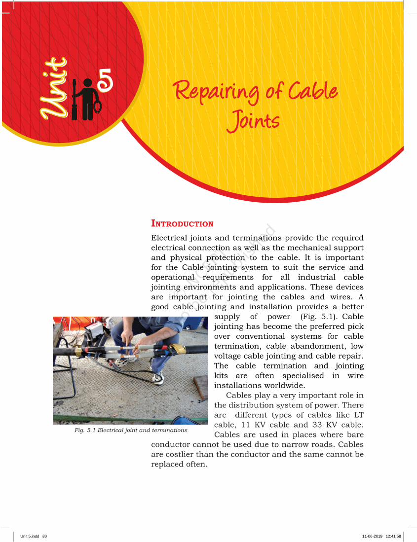
Electrical joints and terminations provide the required electrical connection as well as the mechanical support and physical protection to the cable. It is important for the Cable jointing system to suit the service and operational requirements for all industrial cable jointing environments and applications. These devices are important for jointing the cables and wires. A good cable jointing and installation provides a better
supply of power (Fig. 5.1). Cable jointing has become the preferred pick over conventional systems for cable termination, cable abandonment, low voltage cable jointing and cable repair. The cable termination and jointing kits are often specialised in wire installations worldwide.
Cables play a very important role in the distribution system of power. There are different types of cables like LT cable, 11 KV cable and 33 KV cable. Cables are used in places where bare
conductor cannot be used due to narrow roads. Cables are costlier than the conductor and the same cannot be replaced often.
Fig. 5.1 Electrical joint and terminations
55
Unit 5.indd 80 11-06-2019 12:41:58
REPAIRING OF CABLE JOINTS
81
SESSION 1: ELECTRICAL CABLE JOINTING METHODS
Jointing of power cables should be as simple as twisting and taping the wire. For jointing of a cable variety of in-line adapters and connectors are used. The method used for a cable joint depends on the voltage, type of cable, type of joint, type of connector, application and other factors. Proper tools and equipment are to be used for jointing the cable.
Given below are some important factors to ensure reliable connections, such as� proper size of connectors should be used for a
particular cable,� proper tools and equipment are to be used,� cuts and stripping should be very clean,� proper technique is to be used for cable jointing
and � restoring the insulation, outer-sheath
and armour.
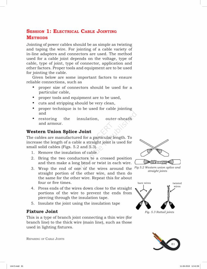
Western Union Splice JointThe cables are manufactured for a particular length. To increase the length of a cable a straight joint is used for small solid cables (Figs. 5.2 and 5.3).
1. Remove the insulation of cable2. Bring the two conductors to a crossed position
and then make a long bend or twist in each wire.3. Wrap the end of one of the wires around the
straight portion of the other wire, and then do the same for the other wire. Repeat this for about four or five times.
4. Press ends of the wires down close to the straight portions of the wire to prevent the ends from piercing through the insulation tape.
5. Insulate the joint using the insulation tape
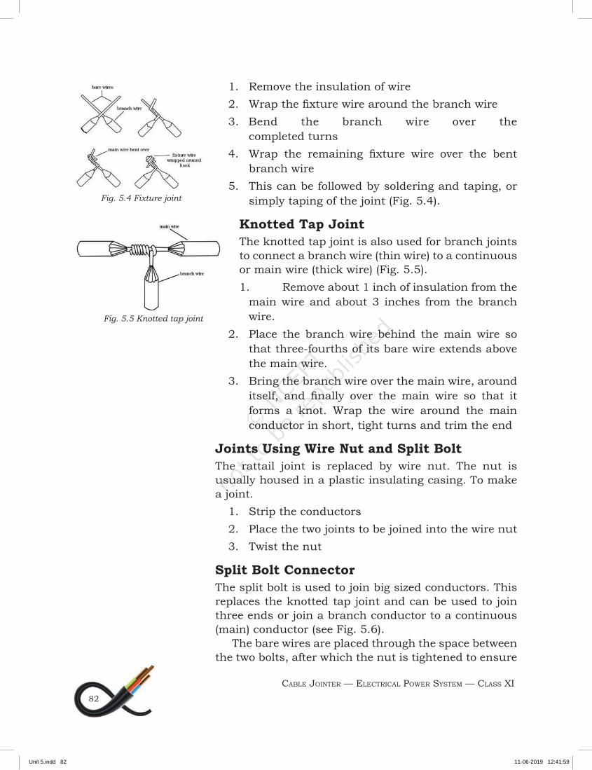
Fixture JointThis is a type of branch joint connecting a thin wire (for branch line) to the thick wire (main line), such as those used in lighting fixtures.
Fig 5.2 Western union splice and straight joints
Fig. 5.3 Rattail joints
bare wires twisted wires
Unit 5.indd 81 11-06-2019 12:41:59
CABLE JOINTER — ELECTRICAL POWER SYSTEM — CLASS XI82
1. Remove the insulation of wire2. Wrap the fixture wire around the branch wire3. Bend the branch wire over the
completed turns4. Wrap the remaining fixture wire over the bent
branch wire5. This can be followed by soldering and taping, or
simply taping of the joint (Fig. 5.4).
Knotted Tap JointThe knotted tap joint is also used for branch joints to connect a branch wire (thin wire) to a continuous or main wire (thick wire) (Fig. 5.5).1. Remove about 1 inch of insulation from the
main wire and about 3 inches from the branch wire.
2. Place the branch wire behind the main wire so that three-fourths of its bare wire extends above the main wire.
3. Bring the branch wire over the main wire, around itself, and finally over the main wire so that it forms a knot. Wrap the wire around the main conductor in short, tight turns and trim the end
Joints Using Wire Nut and Split BoltThe rattail joint is replaced by wire nut. The nut is usually housed in a plastic insulating casing. To make a joint.
1. Strip the conductors2. Place the two joints to be joined into the wire nut3. Twist the nut
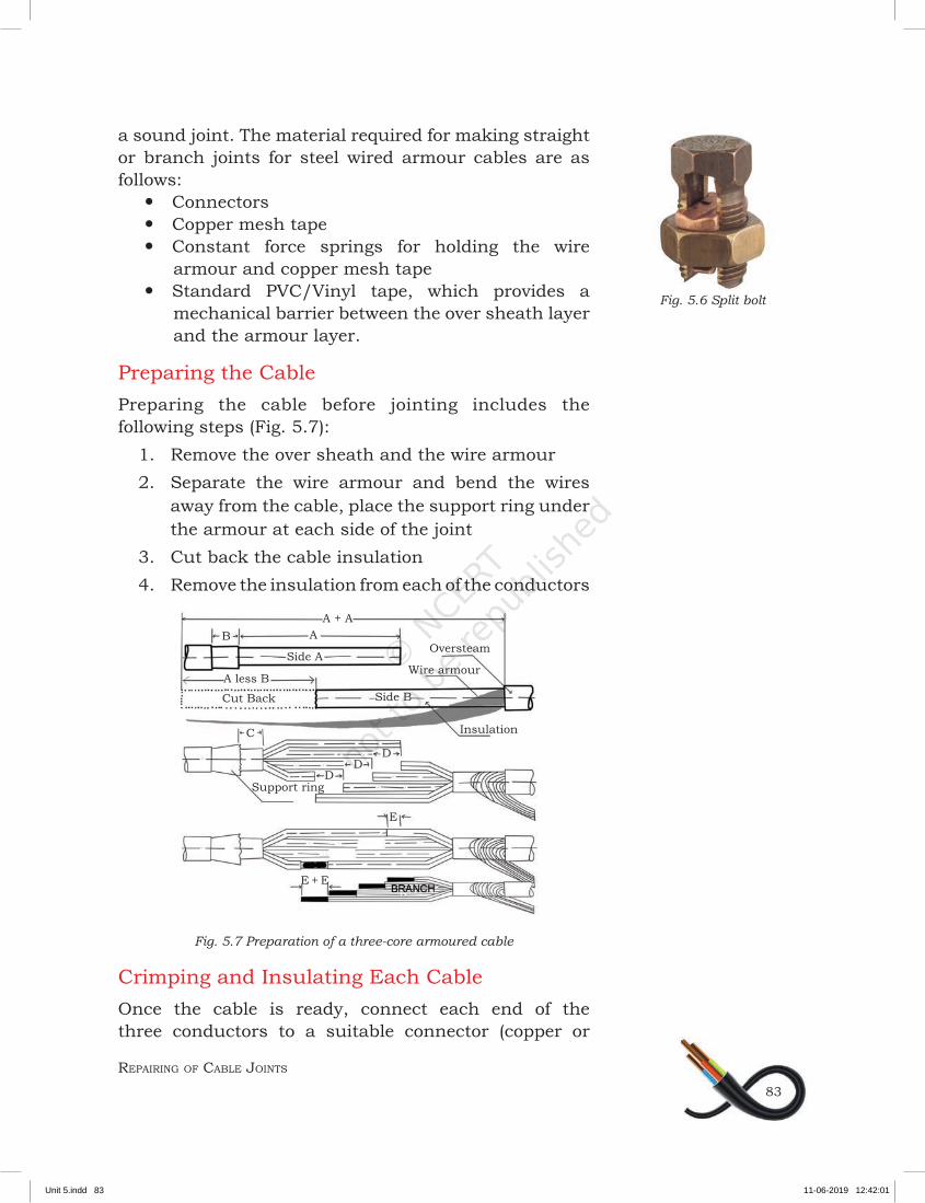
Split Bolt ConnectorThe split bolt is used to join big sized conductors. This replaces the knotted tap joint and can be used to join three ends or join a branch conductor to a continuous (main) conductor (see Fig. 5.6).
The bare wires are placed through the space between the two bolts, after which the nut is tightened to ensure
Fig. 5.5 Knotted tap joint
Fig. 5.4 Fixture joint
Unit 5.indd 82 11-06-2019 12:41:59
REPAIRING OF CABLE JOINTS
83
a sound joint. The material required for making straight or branch joints for steel wired armour cables are as follows:
y Connectors y Copper mesh tape y Constant force springs for holding the wire
armour and copper mesh tape y Standard PVC/Vinyl tape, which provides a
mechanical barrier between the over sheath layer and the armour layer.
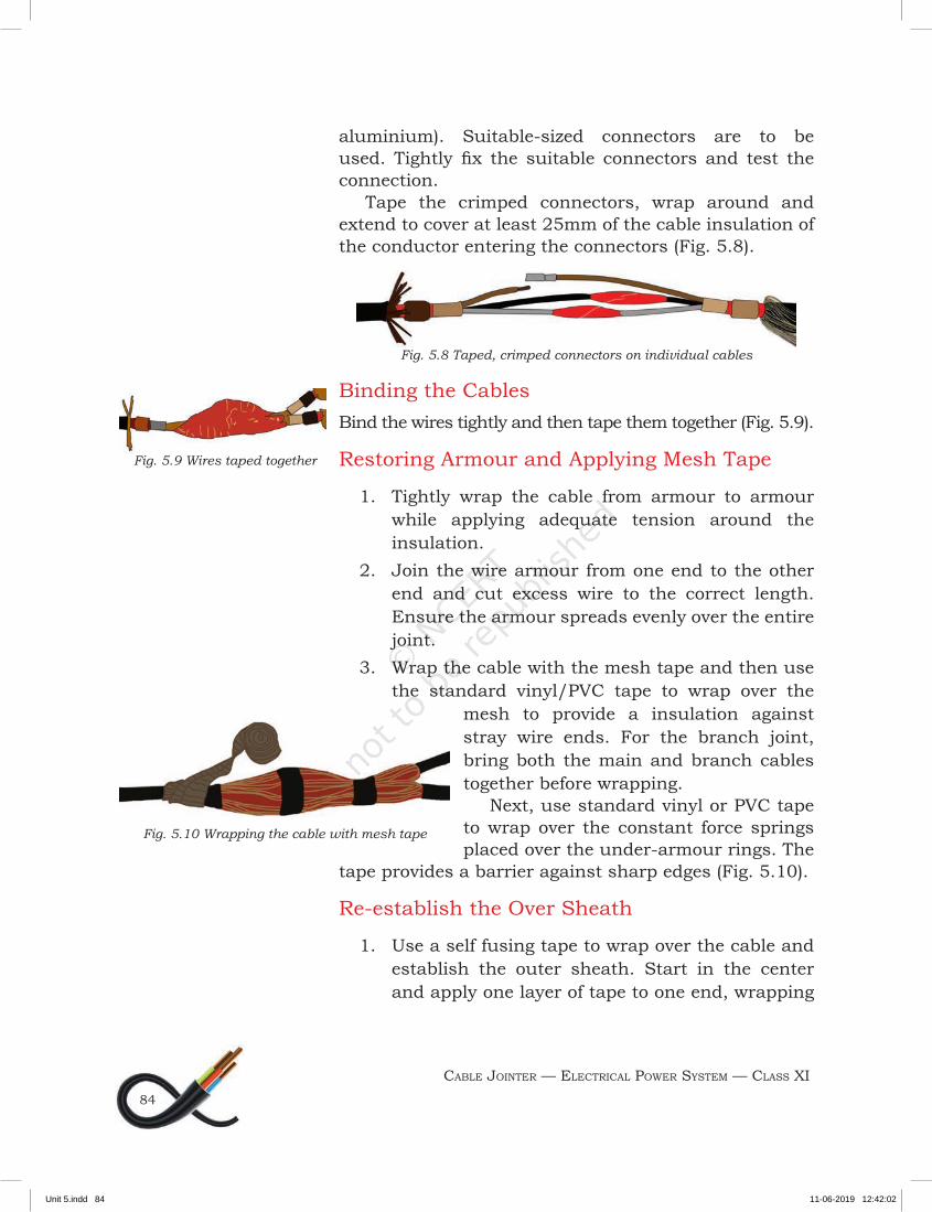
Preparing the CablePreparing the cable before jointing includes the following steps (Fig. 5.7):
1. Remove the over sheath and the wire armour2. Separate the wire armour and bend the wires
away from the cable, place the support ring under the armour at each side of the joint
3. Cut back the cable insulation4. Remove the insulation from each of the conductors
Fig. 5.7 Preparation of a three-core armoured cable
Crimping and Insulating Each CableOnce the cable is ready, connect each end of the three conductors to a suitable connector (copper or
Fig. 5.6 Split bolt
Oversteam
Wire armour
Cut Back
Insulation
Side B
Side A
A + A
E + E
A less B
Support ring
E
DD
D
A B
C
Unit 5.indd 83 11-06-2019 12:42:01
CABLE JOINTER — ELECTRICAL POWER SYSTEM — CLASS XI84
aluminium). Suitable-sized connectors are to be used. Tightly fix the suitable connectors and test the connection.
Tape the crimped connectors, wrap around and extend to cover at least 25mm of the cable insulation of the conductor entering the connectors (Fig. 5.8).
Fig. 5.8 Taped, crimped connectors on individual cables
Binding the CablesBind the wires tightly and then tape them together (Fig. 5.9).
Restoring Armour and Applying Mesh Tape
1. Tightly wrap the cable from armour to armour while applying adequate tension around the insulation.
2. Join the wire armour from one end to the other end and cut excess wire to the correct length. Ensure the armour spreads evenly over the entire joint.
3. Wrap the cable with the mesh tape and then use the standard vinyl/PVC tape to wrap over the
mesh to provide a insulation against stray wire ends. For the branch joint, bring both the main and branch cables together before wrapping.
Next, use standard vinyl or PVC tape to wrap over the constant force springs placed over the under-armour rings. The
tape provides a barrier against sharp edges (Fig. 5.10).
Re-establish the Over Sheath
1. Use a self fusing tape to wrap over the cable and establish the outer sheath. Start in the center and apply one layer of tape to one end, wrapping
Fig. 5.9 Wires taped together
Fig. 5.10 Wrapping the cable with mesh tape
Unit 5.indd 84 11-06-2019 12:42:02
REPAIRING OF CABLE JOINTS
85
over the jacket for at least 25 mm. Apply the tape from the end towards the center so that you have two layers on each side.
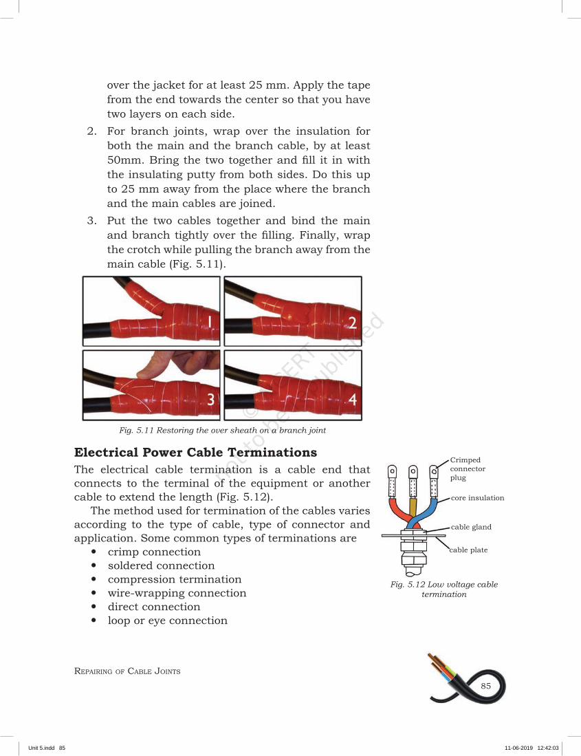
2. For branch joints, wrap over the insulation for both the main and the branch cable, by at least 50mm. Bring the two together and fill it in with the insulating putty from both sides. Do this up to 25 mm away from the place where the branch and the main cables are joined.
3. Put the two cables together and bind the main and branch tightly over the filling. Finally, wrap the crotch while pulling the branch away from the main cable (Fig. 5.11).
Fig. 5.11 Restoring the over sheath on a branch joint
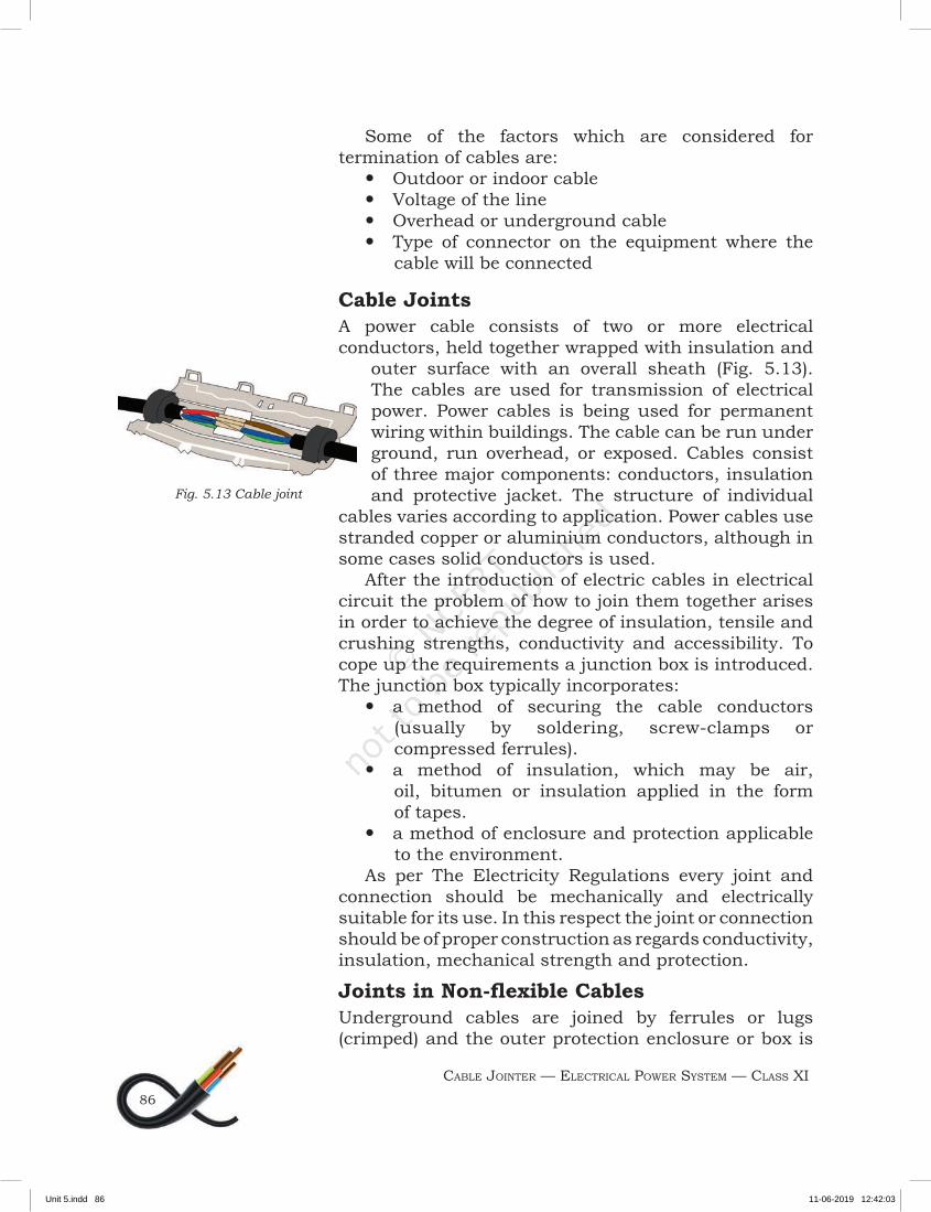
Electrical Power Cable TerminationsThe electrical cable termination is a cable end that connects to the terminal of the equipment or another cable to extend the length (Fig. 5.12).
The method used for termination of the cables varies according to the type of cable, type of connector and application. Some common types of terminations are
y crimp connection y soldered connection y compression termination y wire-wrapping connection y direct connection y loop or eye connection
Fig. 5.12 Low voltage cable termination
Crimped connector plug
core insulation
cable gland
cable plate
Unit 5.indd 85 11-06-2019 12:42:03
CABLE JOINTER — ELECTRICAL POWER SYSTEM — CLASS XI86
Some of the factors which are considered for termination of cables are:
y Outdoor or indoor cable y Voltage of the line y Overhead or underground cable y Type of connector on the equipment where the
cable will be connected
Cable JointsA power cable consists of two or more electrical conductors, held together wrapped with insulation and
outer surface with an overall sheath (Fig. 5.13). The cables are used for transmission of electrical power. Power cables is being used for permanent wiring within buildings. The cable can be run under ground, run overhead, or exposed. Cables consist of three major components: conductors, insulation and protective jacket. The structure of individual
cables varies according to application. Power cables use stranded copper or aluminium conductors, although in some cases solid conductors is used.
After the introduction of electric cables in electrical circuit the problem of how to join them together arises in order to achieve the degree of insulation, tensile and crushing strengths, conductivity and accessibility. To cope up the requirements a junction box is introduced. The junction box typically incorporates:
y a method of securing the cable conductors (usually by soldering, screw-clamps or compressed ferrules).
y a method of insulation, which may be air, oil, bitumen or insulation applied in the form of tapes.
y a method of enclosure and protection applicable to the environment.
As per The Electricity Regulations every joint and connection should be mechanically and electrically suitable for its use. In this respect the joint or connection should be of proper construction as regards conductivity, insulation, mechanical strength and protection.
Joints in Non-flexible CablesUnderground cables are joined by ferrules or lugs (crimped) and the outer protection enclosure or box is
Fig. 5.13 Cable joint
Unit 5.indd 86 11-06-2019 12:42:03
REPAIRING OF CABLE JOINTS
87
usually filled with a plastic or bituminous compound. Such joints are often used above-ground for non-flexible cables and are adequately protected and supported. Other cables which are fixed wiring installations enclosed junction boxes are used to making a joint between two cables. These junction boxes are not securing the cable against strain.
Joints in Flexible CablesJoints in flexible cables are not usually satisfactory because:
1. stranded conductors are not suitable for certain methods of jointing.
2. mechanical tensile strength and resistance are difficult to maintain.
3. fatigue damage may occur when rigid joint is being done.
Some joints and cable connectors are much more acceptable these incorporate terminals or compression fittings suitable for stranded conductors. Cable clamps are used for plugs to reduce the flexing. Heat-shrinkable or pre-stretched sleeving may be adequate in some cases but other circumstances may demand additional protection.
Types of Cable Joints and EquipmentA great majority of failure in cable network is associated with faulty cable jointing. It is, therefore, essential to use proper jointing technique, good quality insulating material and standard accessories for cable jointing. Cable joints are of three types:
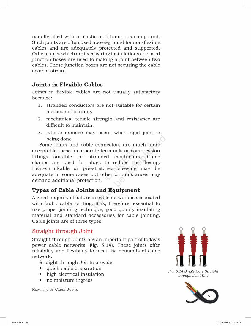
Straight through JointStraight through Joints are an important part of today’s power cable networks (Fig. 5.14). These joints offer reliability and flexibility to meet the demands of cable network.
Straight through Joints provide y quick cable preparation y high electrical insulation y no moisture ingress
Fig. 5.14 Single Core Straight through Joint Kits
Unit 5.indd 87 11-06-2019 12:42:04
CABLE JOINTER — ELECTRICAL POWER SYSTEM — CLASS XI88
of a service cable from a main cable. T-joints are helpful as turning and twisting of cable damages its outer core (Fig. 5.16).
Terminal JointThese type of joints connect cable to switch gear, transformer terminal or to an overhead line (Fig. 5.17).
Conductor JointThe length of distribution lines are in kilometers and one coil of conductor is unable to solve the length problem. Hence, jointing the conductor is necessary.
Britannia JointThis type of joint is made only on solid conductors and cannot be made on stranded conductor. Two conductors to be joined are brought in front of each other of about 6 inch (150 mm) of length. Both the
conductors should be clean. If the conductor is of copper; it should make good electrical connection. Then ends of both conductors are bent through half centimetre and placed on each other. The length of contact portion should be min. 100 mm. This joint should be bound by 14 mm copper wire as shown in Fig. 5.18.
Telephone Joint (Western Union)This joint is used only for solid conductors. It is used for conductors of size 8 SWG or higher size. First, bend is given at 100 to 125 mm from the edge and are placed over each other. Then each one is twisted with another conductor.
Fig. 5.16 T-Joint
Fig. 5.17 Terminal Joint
Fig. 5.18 Britannia Joint
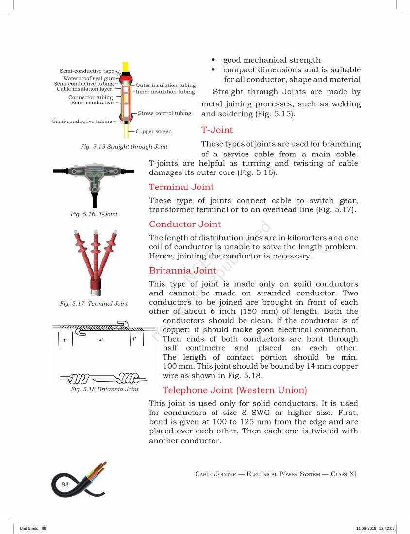
Fig. 5.15 Straight through Joint
Semi-conductive tape
Outer insulation tubingInner insulation tubing
Stress control tubing
Copper screen
Waterproof seal gumSemi-conductive tubingCable insulation layer
Connector tubingSemi-conductive
Semi-conductive tubing
y good mechanical strength y compact dimensions and is suitable
for all conductor, shape and materialStraight through Joints are made by
metal joining processes, such as welding and soldering (Fig. 5.15).
T-JointThese types of joints are used for branching
Unit 5.indd 88 11-06-2019 12:42:05
REPAIRING OF CABLE JOINTS
89
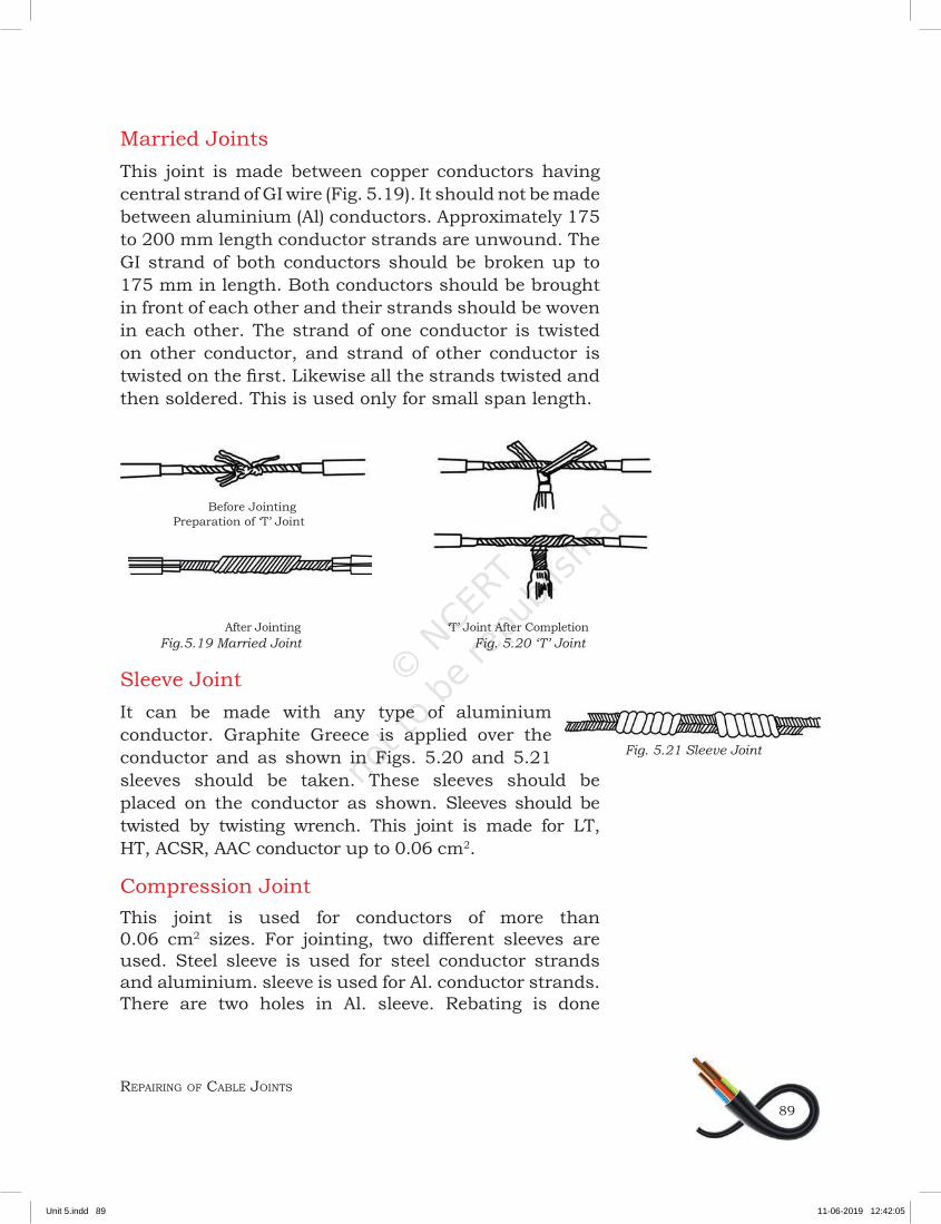
Married JointsThis joint is made between copper conductors having central strand of GI wire (Fig. 5.19). It should not be made between aluminium (Al) conductors. Approximately 175 to 200 mm length conductor strands are unwound. The GI strand of both conductors should be broken up to 175 mm in length. Both conductors should be brought in front of each other and their strands should be woven in each other. The strand of one conductor is twisted on other conductor, and strand of other conductor is twisted on the first. Likewise all the strands twisted and then soldered. This is used only for small span length.
Before Jointing Preparation of ‘T’ Joint
After Jointing ‘T’ Joint After Completion Fig.5.19 Married Joint Fig. 5.20 ‘T’ Joint
Sleeve JointIt can be made with any type of aluminium conductor. Graphite Greece is applied over the conductor and as shown in Figs. 5.20 and 5.21 sleeves should be taken. These sleeves should be placed on the conductor as shown. Sleeves should be twisted by twisting wrench. This joint is made for LT, HT, ACSR, AAC conductor up to 0.06 cm2.
Compression JointThis joint is used for conductors of more than 0.06 cm2 sizes. For jointing, two different sleeves are used. Steel sleeve is used for steel conductor strands and aluminium. sleeve is used for Al. conductor strands. There are two holes in Al. sleeve. Rebating is done
Fig. 5.21 Sleeve Joint
Unit 5.indd 89 11-06-2019 12:42:05
CABLE JOINTER — ELECTRICAL POWER SYSTEM — CLASS XI90
through these holes. Then Al. sleeve to be mounted on one side. The length of steel sleeve is then measured. Its half distance is taken. Suppose it is ‘X’ cm. Then the ends which are to be joined and more to ‘X’ cm distance is taken on the conductor is banded there. The Al. strands are opened up to that point and cut. Steel strand should not be touched during this. They are placed in the steel sleeve. They should be kept in front of each other. Then the center of steel sleeve is compressed through compression machine. Then on the half portion of the right side sleeve be compressed and then on the left half portion. Due to compression the length of sleeve will be increased by 6mm on both sides and it will reach Al. strands. Then Al. sleeve should be measured. It should be halved. Suppose it is ‘Y’ cm then ‘Y’ cm should be measured and marked on both sides of conductor measured from center of steel sleeve. Both parts of conductor are brought in sleeve in front of each other. The filler parts should be filled in the sleeve by Grease until it comes out of the holes. Both the holes are then closed by rivets and hammered by hammer. There is one stencil mark on Al. sleeve. The first compression will be there; afterwards it will be compressed up to one end. Similarly the other part is compressed up to the other end.
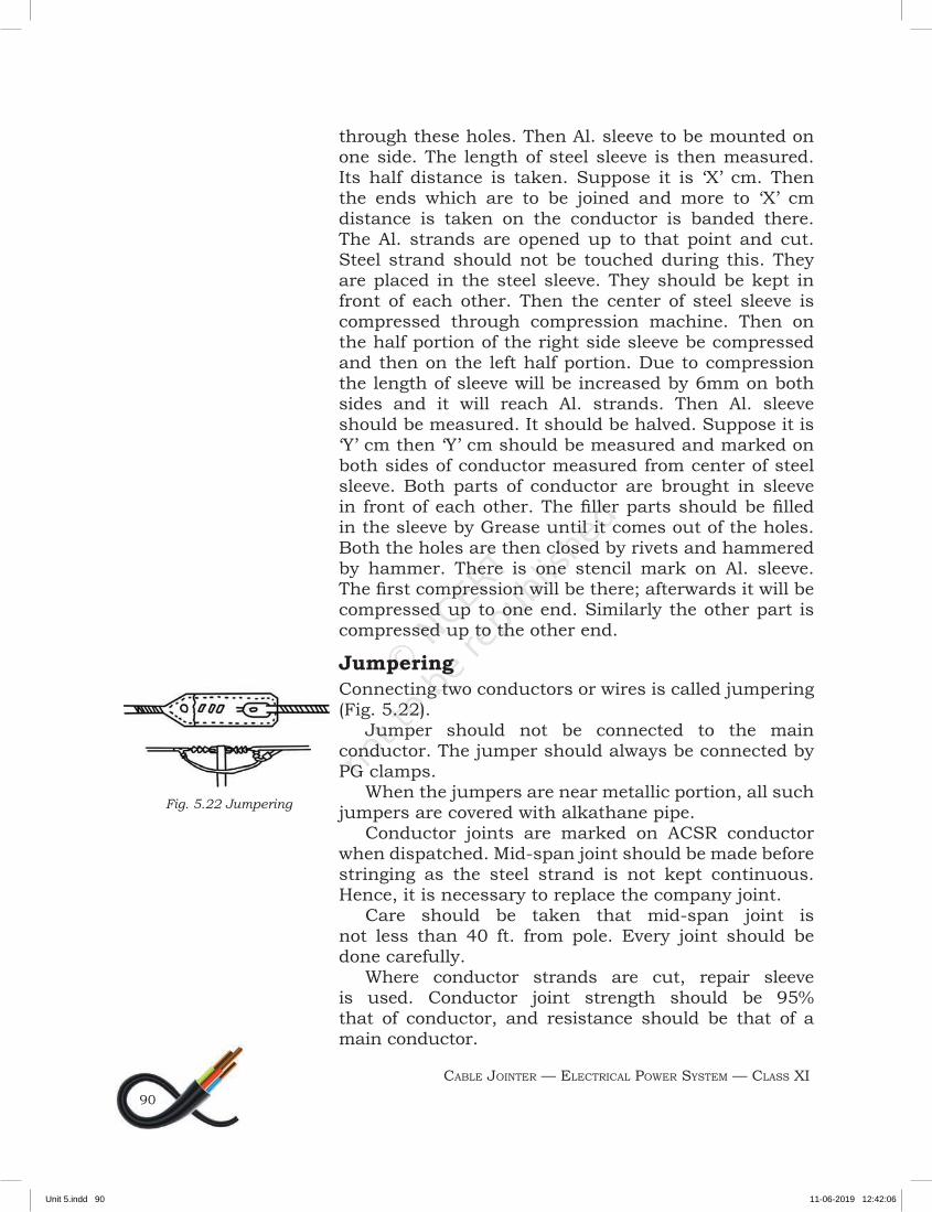
JumperingConnecting two conductors or wires is called jumpering (Fig. 5.22).
Jumper should not be connected to the main conductor. The jumper should always be connected by PG clamps.
When the jumpers are near metallic portion, all such jumpers are covered with alkathane pipe.
Conductor joints are marked on ACSR conductor when dispatched. Mid-span joint should be made before stringing as the steel strand is not kept continuous. Hence, it is necessary to replace the company joint.
Care should be taken that mid-span joint is not less than 40 ft. from pole. Every joint should be done carefully.
Where conductor strands are cut, repair sleeve is used. Conductor joint strength should be 95% that of conductor, and resistance should be that of a main conductor.
Fig. 5.22 Jumpering
Unit 5.indd 90 11-06-2019 12:42:06
REPAIRING OF CABLE JOINTS
91
HV Cable Jointers Tools Using the correct cable tools to prepare industrial and utility cables before cable jointing and terminating reduces catastrophic cable failures. Some of the important cable jointer tools include:
y Cable cutting tool y Cable crimping tool (hydraulic, battery, ratchet)
copper/aluminium cables y Cable spiking tools for LV-HV cables (cartridge/
hydraulic) y Heat shrink gas torches for LV-HV jointing y Screen scoring tools for bonded/easy peel
HV cables y Outer sheath stripping tools, LV-HV cables y Insulation (XLPE) stripping tools, HV cables y Insulated tools for live-working y Cable laying rollers, socks, jacks and pulling
equipment y Conduit duct rods
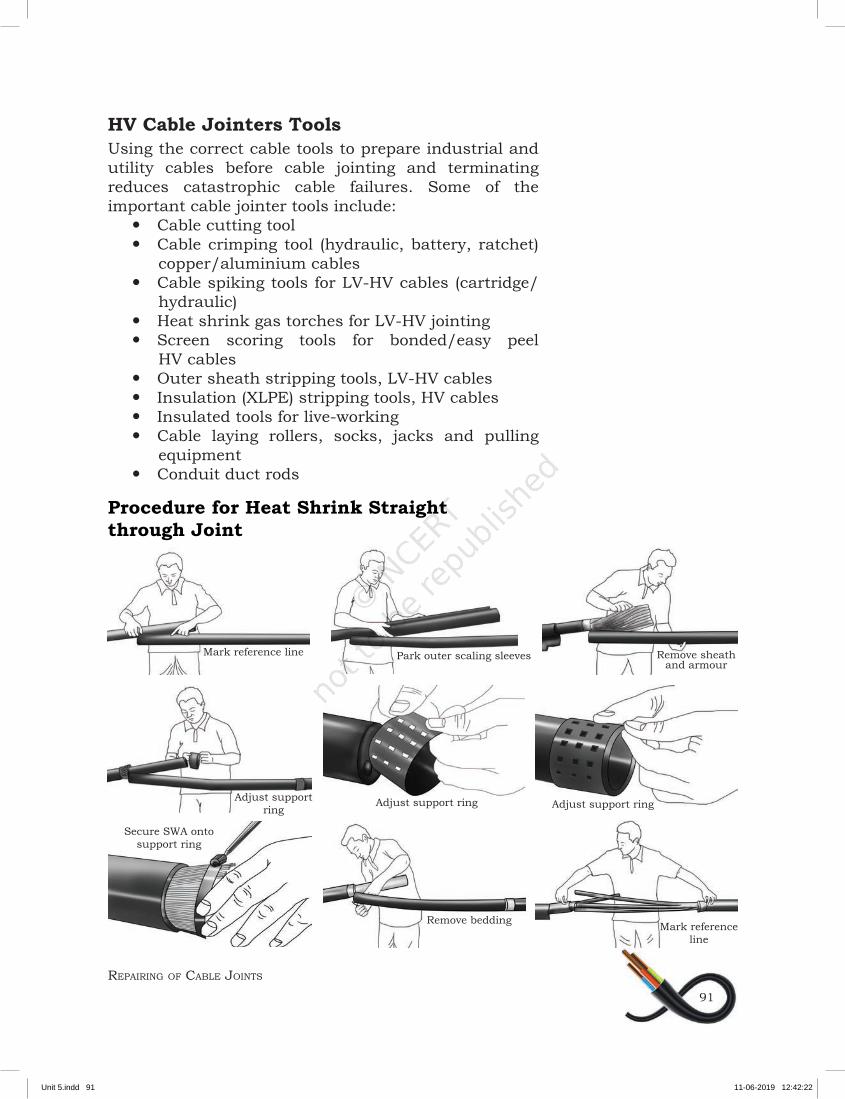
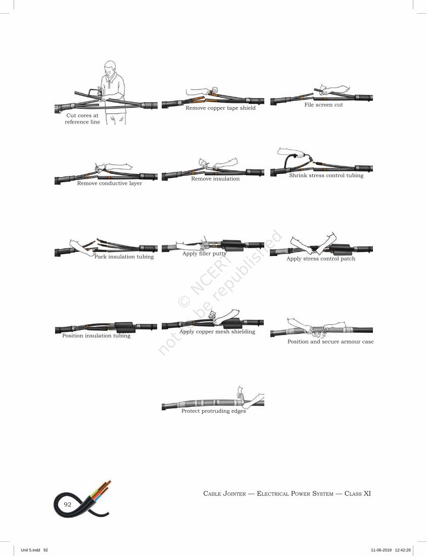
Procedure for Heat Shrink Straight through Joint
Mark reference line Park outer scaling sleeves Remove sheathand armour
Adjust support ring
Adjust support ring
Secure SWA onto support ring
Remove bedding Mark referenceline
Adjust support ring
Unit 5.indd 91 11-06-2019 12:42:22
CABLE JOINTER — ELECTRICAL POWER SYSTEM — CLASS XI92
Cut cores at reference line
Remove conductive layer
Park insulation tubing
Position insulation tubingApply copper mesh shielding
Position and secure armour case
Protect protruding edges
Apply filler puttyApply stress control patch
Remove insulation Shrink stress control tubing
Remove copper tape shield File screen cut
Unit 5.indd 92 11-06-2019 12:42:29
REPAIRING OF CABLE JOINTS
93
Check Your Progress
A. Write short notes on
1. LT cables Joints2. Straight through joint3. Britannia Joint4. T-joint
B. State whether the following statements are True or False
1. Western Union joint are used for all conductors.2. Meried joint should not be made between
aluminium conductors. 3. Crimping is necessary for jointing the cable.
C. Short answer questions
1. List the steps used in preparing of the cable.2. Explain the different types of joints.3. Differentiate between fixture joint and western union
splice joint.4. Explain the procedure for heat shrinking straight
through joint.
Unit 5.indd 93 11-06-2019 12:42:29